EP3349335B1 - Stator and rotating electric machine - Google Patents
Stator and rotating electric machine Download PDFInfo
- Publication number
- EP3349335B1 EP3349335B1 EP16844071.7A EP16844071A EP3349335B1 EP 3349335 B1 EP3349335 B1 EP 3349335B1 EP 16844071 A EP16844071 A EP 16844071A EP 3349335 B1 EP3349335 B1 EP 3349335B1
- Authority
- EP
- European Patent Office
- Prior art keywords
- phase
- winding
- coil
- stator
- concentrated winding
- Prior art date
- Legal status (The legal status is an assumption and is not a legal conclusion. Google has not performed a legal analysis and makes no representation as to the accuracy of the status listed.)
- Active
Links
- 238000004804 winding Methods 0.000 claims description 207
- XEEYBQQBJWHFJM-UHFFFAOYSA-N Iron Chemical group [Fe] XEEYBQQBJWHFJM-UHFFFAOYSA-N 0.000 claims 2
- WABPQHHGFIMREM-UHFFFAOYSA-N lead(0) Chemical compound [Pb] WABPQHHGFIMREM-UHFFFAOYSA-N 0.000 description 12
- 230000007935 neutral effect Effects 0.000 description 7
- 230000000694 effects Effects 0.000 description 3
- RYGMFSIKBFXOCR-UHFFFAOYSA-N Copper Chemical compound [Cu] RYGMFSIKBFXOCR-UHFFFAOYSA-N 0.000 description 2
- 230000005540 biological transmission Effects 0.000 description 2
- 230000000052 comparative effect Effects 0.000 description 2
- 230000003247 decreasing effect Effects 0.000 description 2
- 238000010586 diagram Methods 0.000 description 2
- 238000009413 insulation Methods 0.000 description 2
- 238000000034 method Methods 0.000 description 2
- 230000004048 modification Effects 0.000 description 2
- 238000012986 modification Methods 0.000 description 2
- 229910000831 Steel Inorganic materials 0.000 description 1
- 210000000078 claw Anatomy 0.000 description 1
- 230000006698 induction Effects 0.000 description 1
- 230000016507 interphase Effects 0.000 description 1
- 230000002093 peripheral effect Effects 0.000 description 1
- 239000010959 steel Substances 0.000 description 1
- 230000001360 synchronised effect Effects 0.000 description 1
Images


Classifications
-
- H—ELECTRICITY
- H02—GENERATION; CONVERSION OR DISTRIBUTION OF ELECTRIC POWER
- H02K—DYNAMO-ELECTRIC MACHINES
- H02K3/00—Details of windings
- H02K3/46—Fastening of windings on the stator or rotor structure
- H02K3/52—Fastening salient pole windings or connections thereto
- H02K3/521—Fastening salient pole windings or connections thereto applicable to stators only
- H02K3/522—Fastening salient pole windings or connections thereto applicable to stators only for generally annular cores with salient poles
-
- H—ELECTRICITY
- H02—GENERATION; CONVERSION OR DISTRIBUTION OF ELECTRIC POWER
- H02K—DYNAMO-ELECTRIC MACHINES
- H02K3/00—Details of windings
- H02K3/04—Windings characterised by the conductor shape, form or construction, e.g. with bar conductors
- H02K3/18—Windings for salient poles
-
- H—ELECTRICITY
- H02—GENERATION; CONVERSION OR DISTRIBUTION OF ELECTRIC POWER
- H02K—DYNAMO-ELECTRIC MACHINES
- H02K1/00—Details of the magnetic circuit
- H02K1/06—Details of the magnetic circuit characterised by the shape, form or construction
- H02K1/22—Rotating parts of the magnetic circuit
- H02K1/24—Rotor cores with salient poles ; Variable reluctance rotors
-
- H—ELECTRICITY
- H02—GENERATION; CONVERSION OR DISTRIBUTION OF ELECTRIC POWER
- H02K—DYNAMO-ELECTRIC MACHINES
- H02K3/00—Details of windings
- H02K3/04—Windings characterised by the conductor shape, form or construction, e.g. with bar conductors
- H02K3/12—Windings characterised by the conductor shape, form or construction, e.g. with bar conductors arranged in slots
-
- H—ELECTRICITY
- H02—GENERATION; CONVERSION OR DISTRIBUTION OF ELECTRIC POWER
- H02K—DYNAMO-ELECTRIC MACHINES
- H02K3/00—Details of windings
- H02K3/46—Fastening of windings on the stator or rotor structure
- H02K3/50—Fastening of winding heads, equalising connectors, or connections thereto
-
- H—ELECTRICITY
- H02—GENERATION; CONVERSION OR DISTRIBUTION OF ELECTRIC POWER
- H02K—DYNAMO-ELECTRIC MACHINES
- H02K3/00—Details of windings
- H02K3/46—Fastening of windings on the stator or rotor structure
- H02K3/52—Fastening salient pole windings or connections thereto
-
- H—ELECTRICITY
- H02—GENERATION; CONVERSION OR DISTRIBUTION OF ELECTRIC POWER
- H02K—DYNAMO-ELECTRIC MACHINES
- H02K2203/00—Specific aspects not provided for in the other groups of this subclass relating to the windings
- H02K2203/09—Machines characterised by wiring elements other than wires, e.g. bus rings, for connecting the winding terminations
-
- Y—GENERAL TAGGING OF NEW TECHNOLOGICAL DEVELOPMENTS; GENERAL TAGGING OF CROSS-SECTIONAL TECHNOLOGIES SPANNING OVER SEVERAL SECTIONS OF THE IPC; TECHNICAL SUBJECTS COVERED BY FORMER USPC CROSS-REFERENCE ART COLLECTIONS [XRACs] AND DIGESTS
- Y02—TECHNOLOGIES OR APPLICATIONS FOR MITIGATION OR ADAPTATION AGAINST CLIMATE CHANGE
- Y02T—CLIMATE CHANGE MITIGATION TECHNOLOGIES RELATED TO TRANSPORTATION
- Y02T10/00—Road transport of goods or passengers
- Y02T10/60—Other road transportation technologies with climate change mitigation effect
- Y02T10/64—Electric machine technologies in electromobility
Definitions
- the present invention relates to a stator and a rotating electric machine.
- a stator winding there are concentrated winding in which the coils are formed by concentrating and winding strands for each tooth, and distributed winding in which strands are wound across a plurality of slots and coils having different phases or in-phase phases overlap at a coil end.
- the coil end can be made small as compared with the distributed winding, which is effective for downsizing and high efficiency of the rotating electric machine.
- winding is performed in a concentrated manner on one tooth, it is easier to wind up than the distributed winding, and a coil space factor in the stator slot is also improved.
- JP 2006-299918 A shows a case where there is only one type of winding pattern.
- JP 2013-236455 A shows a stator in which lead-out starting ends and lead-out terminal ends are led out in a shaft line direction at a short distance and are connected with corresponding first to twelfth bus bars, respectively. This eliminates crossovers and complicated laying of wiring to make wiring compact, to thus realize a compact and highly reliable brushless motor.
- winding end positions of the U phase, V phase, and W phase concentrated winding coils are the same, so that wiring must be made from the same winding end position to the U phase, V phase, and W phase connection rings. Since the positions of the stator radial positions of the connection rings of the respective phases are different from each other, the length of the wiring from the winding end position to the connection ring varies depending on the phase. If the wiring from the winding end position to the connection ring becomes long, disconnection of the wire may easily occur due to vibration or the like.
- Claim 1 provides a stator according to the present invention.
- Claim 4 provides a rotating electric machine including a stator according to the present invention.
- the rotating electric machine an electric motor used in an electric vehicle and a hybrid electric vehicle will be described as an example; however, the rotating electric machine of the present invention is not limited to driving an electric vehicle or a hybrid vehicle.
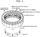
- FIG. 1 is a perspective view of a rotating electric machine as an embodiment of the present invention.
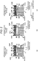
- FIG. 2 is a cross-sectional view of the connection portion of the concentrated winding coil.
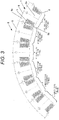
- FIG. 3 is a view showing a winding pattern of each phase of the concentrated winding coil.
- the rotating electric machine 100 includes a concentrated winding stator 8 and a rotor 9 that are arranged coaxially, and in the rotor 9, permanent magnets of N pole and S pole are alternately provided on the side face of the core.
- the rotor 9 is rotatably disposed with respect to the concentrated winding stator 8 via a predetermined gap.
- the concentrated winding stator 8 includes a plurality of cores 5 having a split core structure, and a concentrated winding coil 7 formed by winding an insulating coated conducting wire 1 (see FIG. 2 ) is provided on the teeth 5a (see FIG. 3 ) of each core 5.
- An annular connection plate 2 is disposed on the end face in the axial direction of the core 5, and a coil end is formed.
- a plurality of through holes 20 are opened in the connection plate 2, and a coil terminal 10 of the concentrated winding coil 7 is inserted.
- the number of the concentrated winding coils 7 is 24, and the U phase, the V phase, and the W phase concentrated winding coils 7 are repeatedly arranged eight times.
- each of the cores 5 of the concentrated winding coil 7 has one tooth 5a and is formed into a T shape in plan view so as to define one slot 5b between the pair of cores 5 adjacent to each other in a circumferential direction.
- a plurality of slots 5b aligned in the circumferential direction are formed by assembling the cores 5 in an annular shape.
- the concentrated winding coil 7 may be simply referred to as a coil.
- the concentrated winding coil 7 of the present embodiment is a stator coil with salient pole concentrated winding. Since there are two coil terminals 10 of one winding start and one winding end, the total number of coil terminals 10 is 48.
- the twenty-four winding start coil terminals 101 are disposed on the outer peripheral side of the connection plate 2, and the twenty-four winding start coil terminals 101 are connected to each other to form a neutral point N.
- the twenty-four winding end coil terminals 102 are divided into three phases (U phase, V phase, and W phase) by eight and are arranged at radially displaced positions on the inner circumferential side of the connection plate 2.
- the winding end coil terminals 102 of the same phase are drawn out to the same radius position. Eight U phase coils, eight V phase coils, and eight W phase coils are connected to form the three-phase concentrated winding stators 8.
- the left side of the drawing is the inner diameter side of the concentrated winding coil 7, and the right side of the drawing is the outer diameter side.
- FIG. 2(a) shows a state where the U phase is connected.
- a bobbin 6 is mounted on the core 5 having electromagnetic steel plates laminated thereon, and the concentrated winding coil 7 is wound around the bobbin 6.
- the concentrated winding coil 7 is wound around the recess of the bobbin 6.
- the coil terminals 101 and 102 of an insulating coated conducting wire 1 of the concentrated winding coil 7 are inserted through the connection plate 2 and any one of the four connection rings 3 (3U (U phase), 3V (V phase), 3W (W phase), and 3N (neutral point)).
- connection rings 3 are substantially circular with different diameters so that they can be arranged in an axial end portion (coil end portion) of the stator, and are arranged in one step on the same plane. Furthermore, the arrangement regions of the three connection rings 3U (U phase), 3V (V phase), and 3W (W phase) are substantially equal to the width of the bobbin 6, and the connection ring 3N at the neutral point (N) substantially coincides with the width of a yoke portion 5c of the core 5. Therefore, the four connection rings 3 (3U, 3V, 3W, and 3N) are arranged within the range of the radial width of the concentrated winding stator 8.
- the winding start coil terminal 101 is connected to the connection ring 3N on the outermost periphery arranged on the connection plate 2, and forms the neutral point N.
- the winding end coil terminal 102 is connected to the second connection ring 3U from the innermost circumferential side arranged on the connection plate 2 to form the U phase .
- the through holes 20 are formed in the connection plate 2, and a connection hole 30 is opened in the connection ring 3.
- FIG. 2(b) shows a state where the V phase is connected.
- the winding end coil terminal 102 is connected to the innermost circumferential side connection ring 3V arranged on the connection plate 2 to form the V phase.
- the V phase has the same configuration as U phase.
- FIG. 2(c) shows a state where the W phase is connected.
- the winding end coil terminal 102 is connected to the third connection ring 3W from the innermost circumferential side arranged on the connection plate 2 to form the W phase.
- the W phase has the same configuration as U phase.
- a position in a radial direction around the rotation axis of the rotor 9 is simply referred to as a radial position or a radial position.
- an outer diameter side along the radial direction around the rotation axis of the rotor 9 is simply referred to as an outer diameter side
- an inner diameter side along the radial direction around the rotation axis of the rotor 9 is simply referred to as an inner diameter side.
- the winding end of each coil differs in phase in the radial direction.
- the winding end position of the U phase coil is a fourth turn from the outer diameter side.
- the winding end position of the V phase coil is the innermost diameter side.
- the winding end position of the W phase coil is a second turn from the outer diameter side. In any of the concentrated winding coils 7, the wire diameter and the winding number of the insulating coated conducting wire 1 are equal.
- the winding end of each coil by changing the position of the winding end of each coil depending on the phase while making the wire diameter and the number of windings of the insulating coated conducting wire 1 equal in each phase, the winding end is placed in the vicinity of the connection ring 3 of each phase. That is, in the present embodiment, the winding end position of each coil is disposed closest to the corresponding connection ring 3 among the plurality of connection rings 3. As a result, the length of the lead wire from the winding end to the connection ring 3 can be shortened, so that it is possible to prevent the lead wire, that is, the coil terminal 10 from breaking due to vibration or the like.
- the winding pattern is changed depending on the phase.
- the winding pattern shown as "uppermost stage fourth turn” in FIG. 3 is the winding pattern of the U phase concentrated winding coil 7 shown in FIG. 2(a) .
- the winding pattern shown as "uppermost stage full turn” in FIG. 3 is the winding pattern of the V phase concentrated winding coil 7 shown in FIG. 2(b) .
- the winding pattern shown as "uppermost stage second turn” in FIG. 3 is the winding pattern of the W phase concentrated winding coil 7 shown in FIG. 2(c) .
- the insulating coated conducting wire 1 is wound up to the innermost diameter side at the uppermost stage of the winding.
- the insulating coated conducting wire 1 is wound by, for example, four turns from the outer diameter side to the stage further above the step corresponding to the uppermost stage of the V phase concentrated winding coil 7, the number of windings is reduced by, for example, four turns from the inner diameter side in the stage immediately below the step corresponding to the uppermost stage of the V phase concentrated winding coil 7.
- the insulating coated conducting wire 1 is wound by, for example, two turns from the outer diameter side to the stage further above the step corresponding to the uppermost stage of the V phase concentrated winding coil 7, the number of windings is reduced by, for example, two turns from the inner diameter side in the stage immediately below the step corresponding to the uppermost stage of the V phase concentrated winding coil 7.
- the number of winding patterns (the number of stages and the number of columns) may be different.
- the position of the winding end coil terminal is changed by changing the number of turns of the uppermost stage of the coil on the outer diameter side; however, the position of the winding end coil terminal can also be changed by other methods.
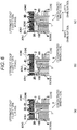
- FIG. 4 is a cross-sectional view of a connection portion of a concentrated winding coil 7 of a second embodiment, in which FIG. 4 (a) shows a state where a U phase is connected, FIG. 4 (b) shows a state where a V phase is connected, and FIG. 4 (c) shows a state where a W phase is connected.
- the winding end of each coil differs in the radial direction depending on the phase.
- the winding end position of the U phase coil is a fifth turn from the outer diameter side.
- the winding end position of the V phase coil is a second turn from the inner diameter side.
- the winding end position of the W phase coil is a first turn from the outer diameter side.
- FIG. 5 is a view showing a winding pattern of each phase of the concentrated winding coil 7 of the second embodiment shown in FIG. 4 .
- the radial position of the winding end coil terminal is changed by appropriately changing the number of windings from the outer diameter side of the uppermost stage of the windings, and for example, in the V phase, the radial position of the winding end coil terminal is changed by appropriately setting the number of windings from the inner diameter side of the uppermost stage of the winding.
- the winding pattern shown as "uppermost stage outer diameter side fifth turn” in FIG. 5 is the winding pattern of the U phase concentrated winding coil 7 shown in FIG. 4 (a) .
- the winding pattern shown as "uppermost stage inner diameter side second turn” in FIG. 5 is the winding pattern of the V phase concentrated winding coil 7 shown in FIG. 4(b) .
- the winding pattern shown as "uppermost stage outer diameter side first turn” in FIG. 5 is the winding pattern of the W phase concentrated winding coil 7 shown in FIG. 4(c) .
- the insulating coated conducting wire 1 is wound by, for example, two turns from the inner diameter side.
- the insulating coated conducting wire 1 is wound, for example, by five turns from the outer diameter side at the uppermost stage of the winding. That is, in the U phase concentrated winding coil 7, the number of turns in the uppermost stage is increased by, for example, three turns than the V phase. Therefore, in the U phase concentrated winding coil 7, in the stage one level below the uppermost stage, by decreasing the number of turns by, for example, three turns from the inner diameter side, the number of turns in the U phase is made equal to the number of turns in the V phase.
- the insulating coated conducting wire 1 is wound by, for example, one turn from the outer diameter side to the step further above the step corresponding to the uppermost stage of the U phase concentrated winding coil 7. Therefore, in the W phase concentrated winding coil 7, in the stage corresponding to the uppermost stage of the U phase concentrated winding coil 7, by decreasing the number of windings, for example, by one turn from the inner diameter side, the number of turns in W phase is made equal to the number of turns in V phase and U phase.
- the radial position of the winding end coil terminal may be changed by appropriately setting the number of windings from the outer diameter side, and the radial position of the winding end coil terminal may be changed by appropriately setting the number of windings from the inner diameter side.
- the winding end can be arranged in the vicinity of the connection ring 3 of each phase; therefore, the length of the lead wire from the winding end to the connection ring 3 can be shortened, and it is possible to prevent the lead wire, that is, the coil terminal 10 from breaking due to vibration or the like.
- FIG. 6 is a cross-sectional view of a connection portion of a concentrated winding coil 7A of a conventional example, in which FIG. 6 (a) shows a state where a U phase is connected, FIG. 6(b) shows a state where a V phase is connected, and FIG. 6(c) shows a state where a W phase is connected.
- FIG. 7 is a view showing a winding pattern of each phase in the conventional example.
- the position in the radial direction of the winding end coil terminal is the same position in each phase, and the winding pattern is the same in each phase.
- FIG. 8 shows a comparative view of the concentrated winding coils 7 of the above described first and second embodiments and the conventional concentrated winding coils 7A.
- the coil space factor in the stator slot is higher than that in the distributed winding, the coil space factor is lower than that in the case of a plurality of winding patterns. Further, in the concentrated winding coil 7A of the conventional example, as described above, the length of the lead wire becomes long depending on the phase, and the mechanical strength of the lead wire may decrease. On the other hand, in the concentrated winding coil 7 of the first and second embodiments in which there are three winding patterns, the coil space factor can be increased and the mechanical strength of the lead wire can also be increased; therefore, the concentrated winding coil 7 is superior to the concentrated winding coil 7A of the conventional example.
- FIG. 9 is a diagram showing a configuration of a vehicle on which the above-described rotating electric machine 100 is mounted, and shows a power train of a four-wheel drive hybrid vehicle.
- This vehicle has an engine 200 and a rotating electric machine 100 as main power on a front wheel side.
- the power generated by the engine 200 and the rotating electric machine 100 is shifted by a transmission 300 and transmitted to the wheels (front wheel side driving wheels).
- a rotating electric machine 150 disposed on a rear wheel side is mechanically connected to the wheels (a rear wheel side driving wheel), and the power generated by the rotating electric machine 150 is transmitted to the rear wheel side driving wheel.
- the rotating electric machine 100 starts the engine 200 and switches the generation of the driving force and the generation of the generating power for recovering the energy at the deceleration of the vehicle as electric energy according to the running state of the vehicle.
- the driving and generating operations of the rotating electric machine 100 are controlled by an electric power converter 400 so as to optimize the torque and the rotational speed according to the driving situation of the vehicle.
- the electric power necessary for driving the rotating electric machine 100 is supplied from a battery 500 via the electric power converter 400.
- electric energy is charged in the battery 500 via the electric power converter 400.
- the rotating electric machine 100 which is a power source on the front wheel side, is disposed between the engine 200 and the transmission 300, and has the above-described configuration.
- the rotating electric machine 150 which is the driving force source on the rear wheel side
- a rotating electric machine similar to the rotating electric machine 100 described above can be used, or another rotating electric machine of a general configuration can be used. Note that it is also applicable to a hybrid system other than a four-wheel drive type.
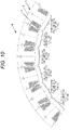
- Fig. 10 shows the winding pattern when the radial position of the winding end coil terminal is six. Even when the future phase number increases to 9 or 12 phases, the radial position of the coil terminal can be set to 9 positions and 12 positions, respectively, in the same way of thinking.
- connection method is described using star connection; however, even in the case of delta connection, the connection ring 3N for neutral point connection disappears, but the present invention can be applied. It should be noted that the present invention can also be applied to the case where the radial position of the winding start coil terminal is different.
- the number of turns of the insulating coated conducting wire 1 is equal in each phase; however, it does not exclude the difference in the number of turns within ⁇ 1 turn caused by the winding pattern and the step pattern of the coil.
- the wire diameter of the insulating coated conducting wire 1 of each coil is equal (the vertical length and the horizontal length of the wire in the case of a square wire or the like); however, it does not exclude the difference due to the tolerance of the copper wire and the elongation of the wire due to the tension of the winding machine at the time of winding.
- a configuration in which a round wire or a square wire is mixed in one coil is not excluded.
- the permanent magnet type rotating electric machine has been explained, but the feature of the present invention is that the position of the winding end coil terminal is different; therefore, the rotor is not a permanent magnet type, but it can also be applied to an induction type, a synchronous reluctance, a claw pole type and the like.
- the inner rotation type is explained, but it is also applicable to an outer rotation type, a linear motor, and an axial gap type.
Landscapes
- Engineering & Computer Science (AREA)
- Power Engineering (AREA)
- Windings For Motors And Generators (AREA)
- Insulation, Fastening Of Motor, Generator Windings (AREA)
Description
- The present invention relates to a stator and a rotating electric machine.
- In the form of a stator winding, there are concentrated winding in which the coils are formed by concentrating and winding strands for each tooth, and distributed winding in which strands are wound across a plurality of slots and coils having different phases or in-phase phases overlap at a coil end. In the concentrated winding, the coil end can be made small as compared with the distributed winding, which is effective for downsizing and high efficiency of the rotating electric machine. Furthermore, since winding is performed in a concentrated manner on one tooth, it is easier to wind up than the distributed winding, and a coil space factor in the stator slot is also improved.
- Generally, there is one type of winding pattern of a concentrated winding coil, and
JP 2006-299918 A -
-
JP 2013-236455 A - In a case where there is one type of winding pattern like a stator described in
JP 2006-299918 A -
Claim 1 provides a stator according to the present invention. Claim 4 provides a rotating electric machine including a stator according to the present invention. Advantageous Effects of Invention - According to the present invention, disconnection can be prevented.
-
- [
FIG. 1] FIG. 1 is a perspective view of a rotating electric machine as an embodiment of the present invention. - [
FIG. 2] FIG. 2 is a cross-sectional view of a connection portion of a concentrated winding coil of a first embodiment, in which (a) shows a state where a U phase is connected, (b) shows a state where a V phase is connected, and (c) shows a state where a W phase is connected. - [
FIG. 3] FIG. 3 is a view showing a winding pattern of each phase of the concentrated winding coil of the first embodiment. - [
FIG. 4] FIG. 4 is a cross-sectional view of a connection portion of a concentrated winding coil of a second embodiment, in which (a) shows a state where a U phase is connected, (b) shows a state where a V phase is connected, and (c) shows a state where a W phase is connected. - [
FIG. 5] FIG. 5 is a view showing a winding pattern of each phase of the concentrated winding coil of the second embodiment. - [
FIG. 6] FIG. 6 is a cross-sectional view of a connection portion of a concentrated winding coil of a conventional example, in which (a) shows a state where a U phase is connected, (b) shows a state where a V phase is connected, and (c) shows a state where a W phase is connected. - [
FIG. 7] FIG. 7 is a view showing a winding pattern of each phase of the concentrated winding coil of the conventional example. - [
FIG. 8] FIG. 8 is a comparative view of the concentrated winding coils of the first and second embodiments and the conventional concentrated winding coils. - [
FIG. 9] FIG. 9 is a diagram showing a configuration of a vehicle on which a rotating electric machine is mounted. - [
FIG. 10] FIG. 10 is a view showing a modification. - An embodiment of the present invention will be described below with reference to the drawings.
- In the following description, as an example of the rotating electric machine, an electric motor used in an electric vehicle and a hybrid electric vehicle will be described as an example; however, the rotating electric machine of the present invention is not limited to driving an electric vehicle or a hybrid vehicle.
-
FIG. 1 is a perspective view of a rotating electric machine as an embodiment of the present invention.FIG. 2 is a cross-sectional view of the connection portion of the concentrated winding coil.FIG. 3 is a view showing a winding pattern of each phase of the concentrated winding coil. - As shown in
FIG. 1 , the rotatingelectric machine 100 includes a concentratedwinding stator 8 and arotor 9 that are arranged coaxially, and in therotor 9, permanent magnets of N pole and S pole are alternately provided on the side face of the core. Therotor 9 is rotatably disposed with respect to the concentratedwinding stator 8 via a predetermined gap. - The
concentrated winding stator 8 includes a plurality ofcores 5 having a split core structure, and a concentratedwinding coil 7 formed by winding an insulating coated conducting wire 1 (seeFIG. 2 ) is provided on theteeth 5a (seeFIG. 3 ) of eachcore 5. Anannular connection plate 2 is disposed on the end face in the axial direction of thecore 5, and a coil end is formed. A plurality of through holes 20 (seeFIG. 2 ) are opened in theconnection plate 2, and acoil terminal 10 of the concentratedwinding coil 7 is inserted. In the present embodiment, the number of the concentratedwinding coils 7 is 24, and the U phase, the V phase, and the W phase concentratedwinding coils 7 are repeatedly arranged eight times. - As shown in
FIG. 3 , each of thecores 5 of the concentratedwinding coil 7 has onetooth 5a and is formed into a T shape in plan view so as to define oneslot 5b between the pair ofcores 5 adjacent to each other in a circumferential direction. A plurality ofslots 5b aligned in the circumferential direction are formed by assembling thecores 5 in an annular shape. In the following description, for convenience, theconcentrated winding coil 7 may be simply referred to as a coil. - The
concentrated winding coil 7 of the present embodiment is a stator coil with salient pole concentrated winding. Since there are twocoil terminals 10 of one winding start and one winding end, the total number ofcoil terminals 10 is 48. The twenty-four windingstart coil terminals 101 are disposed on the outer peripheral side of theconnection plate 2, and the twenty-four windingstart coil terminals 101 are connected to each other to form a neutral point N. The twenty-four windingend coil terminals 102 are divided into three phases (U phase, V phase, and W phase) by eight and are arranged at radially displaced positions on the inner circumferential side of theconnection plate 2. The windingend coil terminals 102 of the same phase are drawn out to the same radius position. Eight U phase coils, eight V phase coils, and eight W phase coils are connected to form the three-phase concentratedwinding stators 8. - In
FIG. 2 , the left side of the drawing is the inner diameter side of the concentratedwinding coil 7, and the right side of the drawing is the outer diameter side. -
FIG. 2(a) shows a state where the U phase is connected. Abobbin 6 is mounted on thecore 5 having electromagnetic steel plates laminated thereon, and the concentratedwinding coil 7 is wound around thebobbin 6. As shown inFIG. 3 , the concentratedwinding coil 7 is wound around the recess of thebobbin 6. In addition, thecoil terminals wire 1 of the concentratedwinding coil 7 are inserted through theconnection plate 2 and any one of the four connection rings 3 (3U (U phase), 3V (V phase), 3W (W phase), and 3N (neutral point)). Here, the fourconnection rings 3 are substantially circular with different diameters so that they can be arranged in an axial end portion (coil end portion) of the stator, and are arranged in one step on the same plane. Furthermore, the arrangement regions of the threeconnection rings 3U (U phase), 3V (V phase), and 3W (W phase) are substantially equal to the width of thebobbin 6, and theconnection ring 3N at the neutral point (N) substantially coincides with the width of ayoke portion 5c of thecore 5. Therefore, the four connection rings 3 (3U, 3V, 3W, and 3N) are arranged within the range of the radial width of the concentratedwinding stator 8. - In
FIG. 2(a) , the windingstart coil terminal 101 is connected to theconnection ring 3N on the outermost periphery arranged on theconnection plate 2, and forms the neutral point N. The windingend coil terminal 102 is connected to thesecond connection ring 3U from the innermost circumferential side arranged on theconnection plate 2 to form the U phase . Although not shown at the neutral point N, at a position where thecoil terminal 10 is inserted through both the U phase and the neutral point N, the throughholes 20 are formed in theconnection plate 2, and aconnection hole 30 is opened in theconnection ring 3. With this structure, inter-phase insulation between the insulating coated conductingwire 1 and theconnection ring 3 of the concentratedwinding coil 7 is maintained with theconnection plate 2 interposed therebetween. In addition, theconnection plate 2 is provided with a ring-shaped wall 21 to position therespective connection rings 3 and ensure phase-to-phase insulation between theconnection rings 3. -
FIG. 2(b) shows a state where the V phase is connected. The windingend coil terminal 102 is connected to the innermost circumferentialside connection ring 3V arranged on theconnection plate 2 to form the V phase. Other than that, the V phase has the same configuration as U phase. -
FIG. 2(c) shows a state where the W phase is connected. The windingend coil terminal 102 is connected to thethird connection ring 3W from the innermost circumferential side arranged on theconnection plate 2 to form the W phase. Other than that, the W phase has the same configuration as U phase. - In the following description, a position in a radial direction around the rotation axis of the
rotor 9 is simply referred to as a radial position or a radial position. Furthermore, in the following description, an outer diameter side along the radial direction around the rotation axis of therotor 9 is simply referred to as an outer diameter side, and an inner diameter side along the radial direction around the rotation axis of therotor 9 is simply referred to as an inner diameter side. - In the present embodiment, the winding end of each coil differs in phase in the radial direction. As shown in
FIG. 2(a) , the winding end position of the U phase coil is a fourth turn from the outer diameter side. As shown inFIG. 2 (b) , the winding end position of the V phase coil is the innermost diameter side. As shown inFIG. 2(c) , the winding end position of the W phase coil is a second turn from the outer diameter side. In any of the concentrated windingcoils 7, the wire diameter and the winding number of the insulatingcoated conducting wire 1 are equal. - As described above, in the present embodiment, by changing the position of the winding end of each coil depending on the phase while making the wire diameter and the number of windings of the insulating
coated conducting wire 1 equal in each phase, the winding end is placed in the vicinity of theconnection ring 3 of each phase. That is, in the present embodiment, the winding end position of each coil is disposed closest to thecorresponding connection ring 3 among the plurality of connection rings 3. As a result, the length of the lead wire from the winding end to theconnection ring 3 can be shortened, so that it is possible to prevent the lead wire, that is, thecoil terminal 10 from breaking due to vibration or the like. - In the present embodiment, since the position in the radial direction of the winding end coil terminal is changed depending on the phase while making the wire diameter and the number of windings of the insulating
coated conducting wire 1 equal in each phase, as shown inFIG. 3 , the winding pattern is changed depending on the phase. - The winding pattern shown as "uppermost stage fourth turn" in
FIG. 3 is the winding pattern of the U phase concentrated windingcoil 7 shown inFIG. 2(a) . The winding pattern shown as "uppermost stage full turn" inFIG. 3 is the winding pattern of the V phase concentrated windingcoil 7 shown inFIG. 2(b) . The winding pattern shown as "uppermost stage second turn" inFIG. 3 is the winding pattern of the W phase concentrated windingcoil 7 shown inFIG. 2(c) . - As shown in
FIGS. 2 and3 , in the V phase concentrated windingcoil 7, in order to make the winding end position the innermost diameter side, the insulatingcoated conducting wire 1 is wound up to the innermost diameter side at the uppermost stage of the winding. - In the U phase concentrated winding
coil 7, since the insulatingcoated conducting wire 1 is wound by, for example, four turns from the outer diameter side to the stage further above the step corresponding to the uppermost stage of the V phase concentrated windingcoil 7, the number of windings is reduced by, for example, four turns from the inner diameter side in the stage immediately below the step corresponding to the uppermost stage of the V phase concentrated windingcoil 7. - Furthermore, in the W phase concentrated winding
coil 7 , since the insulatingcoated conducting wire 1 is wound by, for example, two turns from the outer diameter side to the stage further above the step corresponding to the uppermost stage of the V phase concentrated windingcoil 7, the number of windings is reduced by, for example, two turns from the inner diameter side in the stage immediately below the step corresponding to the uppermost stage of the V phase concentrated windingcoil 7. - In this way, in order to change the position in the radial direction of the winding end coil terminal depending on the phase while making the wire diameter and the winding number of the insulating
coated conducting wire 1 equal in each phase, the number of winding patterns (the number of stages and the number of columns) may be different. - In the first embodiment described above, the position of the winding end coil terminal is changed by changing the number of turns of the uppermost stage of the coil on the outer diameter side; however, the position of the winding end coil terminal can also be changed by other methods.
-
FIG. 4 is a cross-sectional view of a connection portion of a concentrated windingcoil 7 of a second embodiment, in whichFIG. 4 (a) shows a state where a U phase is connected,FIG. 4 (b) shows a state where a V phase is connected, andFIG. 4 (c) shows a state where a W phase is connected. - As shown in
FIG. 4 , the winding end of each coil differs in the radial direction depending on the phase. As shown inFIG. 4(a) , the winding end position of the U phase coil is a fifth turn from the outer diameter side. As shown inFIG. 4(b) , the winding end position of the V phase coil is a second turn from the inner diameter side. As shown inFIG. 4(c) , the winding end position of the W phase coil is a first turn from the outer diameter side. -
FIG. 5 is a view showing a winding pattern of each phase of the concentrated windingcoil 7 of the second embodiment shown inFIG. 4 . In the concentrated windingcoil 7 of the second embodiment, for example, in the U phase and the W phase, the radial position of the winding end coil terminal is changed by appropriately changing the number of windings from the outer diameter side of the uppermost stage of the windings, and for example, in the V phase, the radial position of the winding end coil terminal is changed by appropriately setting the number of windings from the inner diameter side of the uppermost stage of the winding. - The winding pattern shown as "uppermost stage outer diameter side fifth turn" in
FIG. 5 is the winding pattern of the U phase concentrated windingcoil 7 shown inFIG. 4 (a) . The winding pattern shown as "uppermost stage inner diameter side second turn" inFIG. 5 is the winding pattern of the V phase concentrated windingcoil 7 shown inFIG. 4(b) . The winding pattern shown as "uppermost stage outer diameter side first turn" inFIG. 5 is the winding pattern of the W phase concentrated windingcoil 7 shown inFIG. 4(c) . - As shown in
FIGS. 4 and5 , in the V phase concentrated windingcoil 7 of the second embodiment, in the uppermost stage of the winding, the insulatingcoated conducting wire 1 is wound by, for example, two turns from the inner diameter side. In the U phase concentrated windingcoil 7, the insulatingcoated conducting wire 1 is wound, for example, by five turns from the outer diameter side at the uppermost stage of the winding. That is, in the U phase concentrated windingcoil 7, the number of turns in the uppermost stage is increased by, for example, three turns than the V phase. Therefore, in the U phase concentrated windingcoil 7, in the stage one level below the uppermost stage, by decreasing the number of turns by, for example, three turns from the inner diameter side, the number of turns in the U phase is made equal to the number of turns in the V phase. - Further, in the W phase concentrated winding
coil 7, the insulatingcoated conducting wire 1 is wound by, for example, one turn from the outer diameter side to the step further above the step corresponding to the uppermost stage of the U phase concentrated windingcoil 7. Therefore, in the W phase concentrated windingcoil 7, in the stage corresponding to the uppermost stage of the U phase concentrated windingcoil 7, by decreasing the number of windings, for example, by one turn from the inner diameter side, the number of turns in W phase is made equal to the number of turns in V phase and U phase. - As in this second embodiment, in the uppermost stage of the winding, the radial position of the winding end coil terminal may be changed by appropriately setting the number of windings from the outer diameter side, and the radial position of the winding end coil terminal may be changed by appropriately setting the number of windings from the inner diameter side. As a result, the winding end can be arranged in the vicinity of the
connection ring 3 of each phase; therefore, the length of the lead wire from the winding end to theconnection ring 3 can be shortened, and it is possible to prevent the lead wire, that is, thecoil terminal 10 from breaking due to vibration or the like. - Conventional examples of the concentrated winding
coil 7 will be described with reference toFIGS. 6 and7 in order to explain the effect of the present invention easily.FIG. 6 is a cross-sectional view of a connection portion of a concentrated windingcoil 7A of a conventional example, in whichFIG. 6 (a) shows a state where a U phase is connected,FIG. 6(b) shows a state where a V phase is connected, andFIG. 6(c) shows a state where a W phase is connected.FIG. 7 is a view showing a winding pattern of each phase in the conventional example. In the concentrated windingcoil 7A of the conventional example, the position in the radial direction of the winding end coil terminal is the same position in each phase, and the winding pattern is the same in each phase. - In
FIG. 6 , since there is only one position in the radial direction of the coil terminal, for example, the wiring from the winding end to aconnection ring 3V in the V phase shown inFIG. 6(b) , that is, the lead wire is longer than the U phase and the W phase. Therefore, thecoil terminal 10 in the V phase may be broken due to vibration or the like. - As is clear from
FIG. 7 , when there is only one type of winding pattern, there are places where the gap between adjacent coils becomes narrower or wider. Therefore, although a coil space factor in the stator slot in the case of one kind of winding pattern is higher than that in the distributed winding, the coil space factor is lower than that in the case of a plurality of winding patterns. -
FIG. 8 shows a comparative view of the concentrated windingcoils 7 of the above described first and second embodiments and the conventional concentrated windingcoils 7A. - In the concentrated winding
coil 7A of the conventional example, although a coil space factor in the stator slot is higher than that in the distributed winding, the coil space factor is lower than that in the case of a plurality of winding patterns. Further, in the concentrated windingcoil 7A of the conventional example, as described above, the length of the lead wire becomes long depending on the phase, and the mechanical strength of the lead wire may decrease. On the other hand, in the concentrated windingcoil 7 of the first and second embodiments in which there are three winding patterns, the coil space factor can be increased and the mechanical strength of the lead wire can also be increased; therefore, the concentrated windingcoil 7 is superior to the concentrated windingcoil 7A of the conventional example. - With reference to
FIG. 9 , a configuration of a vehicle on which the rotatingelectric machine 100 according to the present embodiment is mounted will be described.FIG. 9 is a diagram showing a configuration of a vehicle on which the above-described rotatingelectric machine 100 is mounted, and shows a power train of a four-wheel drive hybrid vehicle. This vehicle has anengine 200 and a rotatingelectric machine 100 as main power on a front wheel side. The power generated by theengine 200 and the rotatingelectric machine 100 is shifted by atransmission 300 and transmitted to the wheels (front wheel side driving wheels). In driving rear wheels, a rotatingelectric machine 150 disposed on a rear wheel side is mechanically connected to the wheels (a rear wheel side driving wheel), and the power generated by the rotatingelectric machine 150 is transmitted to the rear wheel side driving wheel. - The rotating
electric machine 100 starts theengine 200 and switches the generation of the driving force and the generation of the generating power for recovering the energy at the deceleration of the vehicle as electric energy according to the running state of the vehicle. The driving and generating operations of the rotatingelectric machine 100 are controlled by anelectric power converter 400 so as to optimize the torque and the rotational speed according to the driving situation of the vehicle. The electric power necessary for driving the rotatingelectric machine 100 is supplied from abattery 500 via theelectric power converter 400. In addition, when the rotatingelectric machine 100 is in the power generating operation, electric energy is charged in thebattery 500 via theelectric power converter 400. - Here, the rotating
electric machine 100, which is a power source on the front wheel side, is disposed between theengine 200 and thetransmission 300, and has the above-described configuration. As the rotatingelectric machine 150 which is the driving force source on the rear wheel side, a rotating electric machine similar to the rotatingelectric machine 100 described above can be used, or another rotating electric machine of a general configuration can be used. Note that it is also applicable to a hybrid system other than a four-wheel drive type. - As described above, according to the present invention, it is possible to provide a stator for a rotating electric machine excellent in mechanical strength while maintaining the small and high efficiency characteristics of salient pole concentrated winding.
- According to the above-described embodiment, the following action and effect are achieved.
- (1) The concentrated winding
stator 8 includes multi-phase concentrated windingcoils 7 each having a salient pole concentrated winding, a plurality ofcores 5 having a split core structure formed with a plurality ofteeth 5a around which the multi-phase concentrated windingcoils 7 are wound, and a plurality of connection rings 3 connecting each of the multi-phase concentrated windingcoils 7. The winding end position of each of the multi-phase concentrated windingcoils 7 is disposed closest to thecorresponding connection ring 3 among the plurality of connection rings 3.
As a result, the length of the lead wire from the winding end to theconnection ring 3 can be shortened, so that it is possible to prevent the lead wire, that is, thecoil terminal 10 from breaking due to vibration or the like. Therefore, durability and reliability of the concentrated windingstator 8 can be improved, and the durability and reliability of the rotatingelectric machine 100 including the concentrated windingstator 8 can be improved. - (2) The concentrated winding
stator 8 includes multi-phase concentrated windingcoils 7 each having a salient pole concentrated winding, a plurality ofcores 5 having a split core structure formed with a plurality ofteeth 5a around which the multi-phase concentrated windingcoils 7 are wound, and a plurality of connection rings 3 connecting each of the multi-phase concentrated windingcoils 7. Each of the plurality of connection rings 3 has a different diameter. The winding end position of each of the multi-phase concentrated windingcoils 7 exists at three different positions in the radial direction.
As a result, the length of the lead wire from the winding end to theconnection ring 3 can be shortened, so that it is possible to prevent the lead wire, that is, thecoil terminal 10 from breaking due to vibration or the like. Therefore, durability and reliability of the concentrated windingstator 8 can be improved, and the durability and reliability of the rotatingelectric machine 100 including the concentrated windingstator 8 can be improved. - (3) In each of the concentrated winding
coils 7, the winding end position is made different by changing the number of winding stages and/or the number of rows for each phase. As a result, the number of windings of the insulatingcoated conducting wire 1 can be made equal for each phase, and the amount of generation of the rotating magnetic field in each phase of the concentrated windingcoil 7 can be made equal, so that the operation of the rotatingelectric machine 100 can be stabilized. - It should be noted that the present invention is not limited to the above-described embodiments, but includes various modifications. For example, in
FIG. 2 to FIG. 5 , concentrated winding has been described, but also includes the case of a rotating electric machine having the same problem as concentrated winding. - For example, the above-described embodiments have been described in detail for easy understanding of the present invention, and are not necessarily limited to those having all the configurations described. In addition, a part of the configuration of one embodiment can be replaced by the configuration of another embodiment, and the configuration of another embodiment can be added to the configuration of one embodiment. Further, it is possible to add, delete, and replace other configurations with respect to part of the configuration of each embodiment.
- Although the number of energized phases is three phases, the present invention can also be applied to a larger number of phases (for example, six phases) than three phases. The present invention can also be applied to 6-wire, three phase in the recent invention.
Fig. 10 shows the winding pattern when the radial position of the winding end coil terminal is six. Even when the future phase number increases to 9 or 12 phases, the radial position of the coil terminal can be set to 9 positions and 12 positions, respectively, in the same way of thinking. - In the above description, the connection method is described using star connection; however, even in the case of delta connection, the
connection ring 3N for neutral point connection disappears, but the present invention can be applied. It should be noted that the present invention can also be applied to the case where the radial position of the winding start coil terminal is different. - In the above description, it is a prerequisite that the number of turns of the insulating
coated conducting wire 1 is equal in each phase; however, it does not exclude the difference in the number of turns within ± 1 turn caused by the winding pattern and the step pattern of the coil. Similarly, it is a prerequisite that the wire diameter of the insulatingcoated conducting wire 1 of each coil is equal (the vertical length and the horizontal length of the wire in the case of a square wire or the like); however, it does not exclude the difference due to the tolerance of the copper wire and the elongation of the wire due to the tension of the winding machine at the time of winding. Furthermore, by deforming the copper wire, a configuration in which a round wire or a square wire is mixed in one coil is not excluded. - In the above description, the permanent magnet type rotating electric machine has been explained, but the feature of the present invention is that the position of the winding end coil terminal is different; therefore, the rotor is not a permanent magnet type, but it can also be applied to an induction type, a synchronous reluctance, a claw pole type and the like. Next, the inner rotation type is explained, but it is also applicable to an outer rotation type, a linear motor, and an axial gap type.
-
- 1
- insulating coated conducting wire
- 3, 3N, 3U, 3V, 3W
- connection ring
- 5
- core
- 7
- concentrated winding coil
- 8
- concentrated winding stator
- 9
- rotor
- 10
- coil terminal
- 100
- rotating electric machine
- 101
- winding start coil terminal (coil terminal)
- 102
- winding end coil terminal (coil terminal)
Claims (4)
- A stator (8) comprising:a plurality of multi-phase stator coils (7) each having a salient pole concentrated winding;a stator iron core (5) formed with a plurality of teeth (5a) around which the plurality of multi-phase stator coils (7) are wound;a plurality of substantially circular connection rings (3), each having a different diameter and configured to connect plural of the plurality of multi-phase stator coils (7); anda connection plate (2) comprising a plurality of through holes (20) with a coil terminal (10) of one of the multi-phase stator coils (7) being inserted through one of the through holes (20) and into a corresponding connection hole (30) of a connection ring (3),characterized in thatin each of the multi-phase stator coils (7), a winding end position is made different by changing the number of stages and/or the number of rows of windings for each phase so that the winding end position of each of the multi-phase stator coils (7) is disposed closest in the radial direction to the corresponding connection ring (3) to which the multi-phase stator coil (7) is connected among the plurality of connection rings (3), andwherein the multi-phase stator coils (7) have the same number of turns of windings.
- The stator according to claim 1, wherein the multi-phase stator coils (7) are U phase, V phase, and W phase stator coils, and winding end positions (102) of the U phase, V phase, and W phase stator coils are different from each other in a radial direction.
- The stator according to claim 2, wherein the windings used for the U phase, V phase, and W phase stator coils (7) are wires whose wire diameter is constant, or a square line whose longitudinal length and transverse length are equal.
- A rotating electric machine according to claim 1 comprising:the stator according to any one of claims 1 to 3; anda rotor (9) arranged rotatably via a predetermined gap with respect to a stator iron core (5).
Applications Claiming Priority (2)
| Application Number | Priority Date | Filing Date | Title |
|---|---|---|---|
| JP2015179053 | 2015-09-11 | ||
| PCT/JP2016/072097 WO2017043207A1 (en) | 2015-09-11 | 2016-07-28 | Stator and rotating electric machine |
Publications (3)
| Publication Number | Publication Date |
|---|---|
| EP3349335A1 EP3349335A1 (en) | 2018-07-18 |
| EP3349335A4 EP3349335A4 (en) | 2019-05-01 |
| EP3349335B1 true EP3349335B1 (en) | 2021-01-27 |
Family
ID=58239369
Family Applications (1)
| Application Number | Title | Priority Date | Filing Date |
|---|---|---|---|
| EP16844071.7A Active EP3349335B1 (en) | 2015-09-11 | 2016-07-28 | Stator and rotating electric machine |
Country Status (5)
| Country | Link |
|---|---|
| US (1) | US10862361B2 (en) |
| EP (1) | EP3349335B1 (en) |
| JP (1) | JP6498775B2 (en) |
| CN (1) | CN108028568B (en) |
| WO (1) | WO2017043207A1 (en) |
Families Citing this family (1)
| Publication number | Priority date | Publication date | Assignee | Title |
|---|---|---|---|---|
| CN112953073B (en) * | 2021-01-28 | 2021-10-08 | 浙江方正电机股份有限公司 | End integrated module of flat copper wire oil-cooled motor stator and stator |
Family Cites Families (10)
| Publication number | Priority date | Publication date | Assignee | Title |
|---|---|---|---|---|
| JP3613262B2 (en) * | 2002-04-26 | 2005-01-26 | 三菱電機株式会社 | Rotating electric machine and manufacturing method thereof |
| US7737598B2 (en) * | 2004-08-09 | 2010-06-15 | A. O. Smith Corporation | Electric motor having a stator |
| JP4396630B2 (en) * | 2005-12-26 | 2010-01-13 | トヨタ自動車株式会社 | Winding method and coil |
| US7936100B2 (en) * | 2007-04-02 | 2011-05-03 | Hitachi, Ltd. | Stator for rotating machine and rotating machine using the same |
| JP5227532B2 (en) | 2007-04-02 | 2013-07-03 | 日立オートモティブシステムズ株式会社 | Semiconductor module for inverter circuit |
| JP5140389B2 (en) | 2007-11-22 | 2013-02-06 | 株式会社日立製作所 | Stator for rotating electric machine and rotating electric machine using the same |
| JP5016969B2 (en) * | 2007-04-25 | 2012-09-05 | 日立オートモティブシステムズ株式会社 | Power distribution parts for rotating electrical machines |
| DE102011078026A1 (en) | 2011-06-23 | 2012-12-27 | Siemens Aktiengesellschaft | Circuit carrier for the wiring of the tooth coil windings of a stator of an electrical machine and kit, comprising such a circuit carrier |
| JP2013236455A (en) | 2012-05-08 | 2013-11-21 | Asmo Co Ltd | Stator and motor |
| JP6113606B2 (en) * | 2013-08-27 | 2017-04-12 | 日立金属株式会社 | Power collection / retention member holding structure, electric motor, and electric motor manufacturing method |
-
2016
- 2016-07-28 CN CN201680052570.2A patent/CN108028568B/en active Active
- 2016-07-28 WO PCT/JP2016/072097 patent/WO2017043207A1/en active Application Filing
- 2016-07-28 US US15/758,467 patent/US10862361B2/en active Active
- 2016-07-28 JP JP2017539057A patent/JP6498775B2/en active Active
- 2016-07-28 EP EP16844071.7A patent/EP3349335B1/en active Active
Non-Patent Citations (1)
| Title |
|---|
| None * |
Also Published As
| Publication number | Publication date |
|---|---|
| US20180248431A1 (en) | 2018-08-30 |
| US10862361B2 (en) | 2020-12-08 |
| CN108028568B (en) | 2019-11-26 |
| EP3349335A1 (en) | 2018-07-18 |
| WO2017043207A1 (en) | 2017-03-16 |
| JPWO2017043207A1 (en) | 2018-02-22 |
| CN108028568A (en) | 2018-05-11 |
| EP3349335A4 (en) | 2019-05-01 |
| JP6498775B2 (en) | 2019-04-10 |
Similar Documents
| Publication | Publication Date | Title |
|---|---|---|
| JP5040303B2 (en) | Rotating electric machine | |
| JP6010416B2 (en) | 3-phase permanent magnet motor | |
| US7834506B2 (en) | Winding structure of rotating electric machine | |
| US9203289B2 (en) | Stator of rotary electric machine | |
| EP3331139B1 (en) | Rotary electric machine | |
| EP3355446B1 (en) | Rotary electric machine | |
| WO2017110760A1 (en) | Rotating electrical machine and method of manufacturing same | |
| US20130015742A1 (en) | Synchronous motor | |
| WO2021108767A1 (en) | Stator winding with alternating winding pitches | |
| US20220263356A1 (en) | Motor | |
| EP3349335B1 (en) | Stator and rotating electric machine | |
| JP2012222963A (en) | Rotary electric machine | |
| JP5703918B2 (en) | Rotating electric machine stator | |
| US20230318382A1 (en) | Stator and motor | |
| JP6651426B2 (en) | Stator of rotating electric machine, and rotating electric machine provided with the same | |
| JP6582973B2 (en) | Rotating electric machine and manufacturing method thereof | |
| JP2010154648A (en) | Motor | |
| CN213367495U (en) | Stator structure of three-phase external rotor motor | |
| JP6889066B2 (en) | Stator and motor | |
| CN118100493A (en) | Electric drive component and electric drive | |
| WO2021067713A1 (en) | Wound-field synchronous machines and control | |
| KR20210125211A (en) | Terminal device for driving motor of vehicle | |
| JP2012205387A (en) | Rotary electric machine |
Legal Events
| Date | Code | Title | Description |
|---|---|---|---|
| STAA | Information on the status of an ep patent application or granted ep patent |
Free format text: STATUS: THE INTERNATIONAL PUBLICATION HAS BEEN MADE |
|
| PUAI | Public reference made under article 153(3) epc to a published international application that has entered the european phase |
Free format text: ORIGINAL CODE: 0009012 |
|
| STAA | Information on the status of an ep patent application or granted ep patent |
Free format text: STATUS: REQUEST FOR EXAMINATION WAS MADE |
|
| 17P | Request for examination filed |
Effective date: 20180226 |
|
| AK | Designated contracting states |
Kind code of ref document: A1 Designated state(s): AL AT BE BG CH CY CZ DE DK EE ES FI FR GB GR HR HU IE IS IT LI LT LU LV MC MK MT NL NO PL PT RO RS SE SI SK SM TR |
|
| AX | Request for extension of the european patent |
Extension state: BA ME |
|
| DAV | Request for validation of the european patent (deleted) | ||
| DAX | Request for extension of the european patent (deleted) | ||
| REG | Reference to a national code |
Ref country code: DE Ref legal event code: R079 Ref document number: 602016052197 Country of ref document: DE Free format text: PREVIOUS MAIN CLASS: H02K0003500000 Ipc: H02K0003520000 |
|
| A4 | Supplementary search report drawn up and despatched |
Effective date: 20190401 |
|
| RIC1 | Information provided on ipc code assigned before grant |
Ipc: H02K 3/52 20060101AFI20190326BHEP |
|
| STAA | Information on the status of an ep patent application or granted ep patent |
Free format text: STATUS: EXAMINATION IS IN PROGRESS |
|
| 17Q | First examination report despatched |
Effective date: 20200115 |
|
| GRAP | Despatch of communication of intention to grant a patent |
Free format text: ORIGINAL CODE: EPIDOSNIGR1 |
|
| STAA | Information on the status of an ep patent application or granted ep patent |
Free format text: STATUS: GRANT OF PATENT IS INTENDED |
|
| INTG | Intention to grant announced |
Effective date: 20201106 |
|
| GRAS | Grant fee paid |
Free format text: ORIGINAL CODE: EPIDOSNIGR3 |
|
| GRAA | (expected) grant |
Free format text: ORIGINAL CODE: 0009210 |
|
| STAA | Information on the status of an ep patent application or granted ep patent |
Free format text: STATUS: THE PATENT HAS BEEN GRANTED |
|
| AK | Designated contracting states |
Kind code of ref document: B1 Designated state(s): AL AT BE BG CH CY CZ DE DK EE ES FI FR GB GR HR HU IE IS IT LI LT LU LV MC MK MT NL NO PL PT RO RS SE SI SK SM TR |
|
| REG | Reference to a national code |
Ref country code: GB Ref legal event code: FG4D |
|
| REG | Reference to a national code |
Ref country code: CH Ref legal event code: EP |
|
| REG | Reference to a national code |
Ref country code: AT Ref legal event code: REF Ref document number: 1359216 Country of ref document: AT Kind code of ref document: T Effective date: 20210215 |
|
| REG | Reference to a national code |
Ref country code: IE Ref legal event code: FG4D |
|
| REG | Reference to a national code |
Ref country code: DE Ref legal event code: R096 Ref document number: 602016052197 Country of ref document: DE |
|
| REG | Reference to a national code |
Ref country code: NL Ref legal event code: MP Effective date: 20210127 |
|
| REG | Reference to a national code |
Ref country code: LT Ref legal event code: MG9D |
|
| REG | Reference to a national code |
Ref country code: AT Ref legal event code: MK05 Ref document number: 1359216 Country of ref document: AT Kind code of ref document: T Effective date: 20210127 |
|
| PG25 | Lapsed in a contracting state [announced via postgrant information from national office to epo] |
Ref country code: BG Free format text: LAPSE BECAUSE OF FAILURE TO SUBMIT A TRANSLATION OF THE DESCRIPTION OR TO PAY THE FEE WITHIN THE PRESCRIBED TIME-LIMIT Effective date: 20210427 Ref country code: LT Free format text: LAPSE BECAUSE OF FAILURE TO SUBMIT A TRANSLATION OF THE DESCRIPTION OR TO PAY THE FEE WITHIN THE PRESCRIBED TIME-LIMIT Effective date: 20210127 Ref country code: FI Free format text: LAPSE BECAUSE OF FAILURE TO SUBMIT A TRANSLATION OF THE DESCRIPTION OR TO PAY THE FEE WITHIN THE PRESCRIBED TIME-LIMIT Effective date: 20210127 Ref country code: GR Free format text: LAPSE BECAUSE OF FAILURE TO SUBMIT A TRANSLATION OF THE DESCRIPTION OR TO PAY THE FEE WITHIN THE PRESCRIBED TIME-LIMIT Effective date: 20210428 Ref country code: HR Free format text: LAPSE BECAUSE OF FAILURE TO SUBMIT A TRANSLATION OF THE DESCRIPTION OR TO PAY THE FEE WITHIN THE PRESCRIBED TIME-LIMIT Effective date: 20210127 Ref country code: NO Free format text: LAPSE BECAUSE OF FAILURE TO SUBMIT A TRANSLATION OF THE DESCRIPTION OR TO PAY THE FEE WITHIN THE PRESCRIBED TIME-LIMIT Effective date: 20210427 Ref country code: PT Free format text: LAPSE BECAUSE OF FAILURE TO SUBMIT A TRANSLATION OF THE DESCRIPTION OR TO PAY THE FEE WITHIN THE PRESCRIBED TIME-LIMIT Effective date: 20210527 |
|
| PG25 | Lapsed in a contracting state [announced via postgrant information from national office to epo] |
Ref country code: AT Free format text: LAPSE BECAUSE OF FAILURE TO SUBMIT A TRANSLATION OF THE DESCRIPTION OR TO PAY THE FEE WITHIN THE PRESCRIBED TIME-LIMIT Effective date: 20210127 Ref country code: RS Free format text: LAPSE BECAUSE OF FAILURE TO SUBMIT A TRANSLATION OF THE DESCRIPTION OR TO PAY THE FEE WITHIN THE PRESCRIBED TIME-LIMIT Effective date: 20210127 Ref country code: LV Free format text: LAPSE BECAUSE OF FAILURE TO SUBMIT A TRANSLATION OF THE DESCRIPTION OR TO PAY THE FEE WITHIN THE PRESCRIBED TIME-LIMIT Effective date: 20210127 Ref country code: PL Free format text: LAPSE BECAUSE OF FAILURE TO SUBMIT A TRANSLATION OF THE DESCRIPTION OR TO PAY THE FEE WITHIN THE PRESCRIBED TIME-LIMIT Effective date: 20210127 Ref country code: SE Free format text: LAPSE BECAUSE OF FAILURE TO SUBMIT A TRANSLATION OF THE DESCRIPTION OR TO PAY THE FEE WITHIN THE PRESCRIBED TIME-LIMIT Effective date: 20210127 |
|
| PG25 | Lapsed in a contracting state [announced via postgrant information from national office to epo] |
Ref country code: IS Free format text: LAPSE BECAUSE OF FAILURE TO SUBMIT A TRANSLATION OF THE DESCRIPTION OR TO PAY THE FEE WITHIN THE PRESCRIBED TIME-LIMIT Effective date: 20210527 |
|
| REG | Reference to a national code |
Ref country code: DE Ref legal event code: R081 Ref document number: 602016052197 Country of ref document: DE Owner name: HITACHI ASTEMO, LTD., HITACHINAKA-SHI, JP Free format text: FORMER OWNER: HITACHI AUTOMOTIVE SYSTEMS, LTD., HITACHINAKA-SHI, IBARAKI, JP |
|
| REG | Reference to a national code |
Ref country code: DE Ref legal event code: R097 Ref document number: 602016052197 Country of ref document: DE |
|
| PG25 | Lapsed in a contracting state [announced via postgrant information from national office to epo] |
Ref country code: CZ Free format text: LAPSE BECAUSE OF FAILURE TO SUBMIT A TRANSLATION OF THE DESCRIPTION OR TO PAY THE FEE WITHIN THE PRESCRIBED TIME-LIMIT Effective date: 20210127 Ref country code: EE Free format text: LAPSE BECAUSE OF FAILURE TO SUBMIT A TRANSLATION OF THE DESCRIPTION OR TO PAY THE FEE WITHIN THE PRESCRIBED TIME-LIMIT Effective date: 20210127 Ref country code: SM Free format text: LAPSE BECAUSE OF FAILURE TO SUBMIT A TRANSLATION OF THE DESCRIPTION OR TO PAY THE FEE WITHIN THE PRESCRIBED TIME-LIMIT Effective date: 20210127 |
|
| PG25 | Lapsed in a contracting state [announced via postgrant information from national office to epo] |
Ref country code: DK Free format text: LAPSE BECAUSE OF FAILURE TO SUBMIT A TRANSLATION OF THE DESCRIPTION OR TO PAY THE FEE WITHIN THE PRESCRIBED TIME-LIMIT Effective date: 20210127 Ref country code: RO Free format text: LAPSE BECAUSE OF FAILURE TO SUBMIT A TRANSLATION OF THE DESCRIPTION OR TO PAY THE FEE WITHIN THE PRESCRIBED TIME-LIMIT Effective date: 20210127 Ref country code: SK Free format text: LAPSE BECAUSE OF FAILURE TO SUBMIT A TRANSLATION OF THE DESCRIPTION OR TO PAY THE FEE WITHIN THE PRESCRIBED TIME-LIMIT Effective date: 20210127 |
|
| PLBE | No opposition filed within time limit |
Free format text: ORIGINAL CODE: 0009261 |
|
| STAA | Information on the status of an ep patent application or granted ep patent |
Free format text: STATUS: NO OPPOSITION FILED WITHIN TIME LIMIT |
|
| 26N | No opposition filed |
Effective date: 20211028 |
|
| PG25 | Lapsed in a contracting state [announced via postgrant information from national office to epo] |
Ref country code: ES Free format text: LAPSE BECAUSE OF FAILURE TO SUBMIT A TRANSLATION OF THE DESCRIPTION OR TO PAY THE FEE WITHIN THE PRESCRIBED TIME-LIMIT Effective date: 20210127 Ref country code: AL Free format text: LAPSE BECAUSE OF FAILURE TO SUBMIT A TRANSLATION OF THE DESCRIPTION OR TO PAY THE FEE WITHIN THE PRESCRIBED TIME-LIMIT Effective date: 20210127 |
|
| PG25 | Lapsed in a contracting state [announced via postgrant information from national office to epo] |
Ref country code: SI Free format text: LAPSE BECAUSE OF FAILURE TO SUBMIT A TRANSLATION OF THE DESCRIPTION OR TO PAY THE FEE WITHIN THE PRESCRIBED TIME-LIMIT Effective date: 20210127 |
|
| REG | Reference to a national code |
Ref country code: CH Ref legal event code: PL |
|
| GBPC | Gb: european patent ceased through non-payment of renewal fee |
Effective date: 20210728 |
|
| PG25 | Lapsed in a contracting state [announced via postgrant information from national office to epo] |
Ref country code: MC Free format text: LAPSE BECAUSE OF FAILURE TO SUBMIT A TRANSLATION OF THE DESCRIPTION OR TO PAY THE FEE WITHIN THE PRESCRIBED TIME-LIMIT Effective date: 20210127 |
|
| REG | Reference to a national code |
Ref country code: BE Ref legal event code: MM Effective date: 20210731 |
|
| PG25 | Lapsed in a contracting state [announced via postgrant information from national office to epo] |
Ref country code: LI Free format text: LAPSE BECAUSE OF NON-PAYMENT OF DUE FEES Effective date: 20210731 Ref country code: IT Free format text: LAPSE BECAUSE OF FAILURE TO SUBMIT A TRANSLATION OF THE DESCRIPTION OR TO PAY THE FEE WITHIN THE PRESCRIBED TIME-LIMIT Effective date: 20210127 Ref country code: GB Free format text: LAPSE BECAUSE OF NON-PAYMENT OF DUE FEES Effective date: 20210728 Ref country code: CH Free format text: LAPSE BECAUSE OF NON-PAYMENT OF DUE FEES Effective date: 20210731 |
|
| PG25 | Lapsed in a contracting state [announced via postgrant information from national office to epo] |
Ref country code: IS Free format text: LAPSE BECAUSE OF FAILURE TO SUBMIT A TRANSLATION OF THE DESCRIPTION OR TO PAY THE FEE WITHIN THE PRESCRIBED TIME-LIMIT Effective date: 20210527 Ref country code: LU Free format text: LAPSE BECAUSE OF NON-PAYMENT OF DUE FEES Effective date: 20210728 Ref country code: FR Free format text: LAPSE BECAUSE OF NON-PAYMENT OF DUE FEES Effective date: 20210731 |
|
| PG25 | Lapsed in a contracting state [announced via postgrant information from national office to epo] |
Ref country code: IE Free format text: LAPSE BECAUSE OF NON-PAYMENT OF DUE FEES Effective date: 20210728 Ref country code: BE Free format text: LAPSE BECAUSE OF NON-PAYMENT OF DUE FEES Effective date: 20210731 |
|
| PG25 | Lapsed in a contracting state [announced via postgrant information from national office to epo] |
Ref country code: HU Free format text: LAPSE BECAUSE OF FAILURE TO SUBMIT A TRANSLATION OF THE DESCRIPTION OR TO PAY THE FEE WITHIN THE PRESCRIBED TIME-LIMIT; INVALID AB INITIO Effective date: 20160728 |
|
| PG25 | Lapsed in a contracting state [announced via postgrant information from national office to epo] |
Ref country code: NL Free format text: LAPSE BECAUSE OF NON-PAYMENT OF DUE FEES Effective date: 20210127 Ref country code: CY Free format text: LAPSE BECAUSE OF FAILURE TO SUBMIT A TRANSLATION OF THE DESCRIPTION OR TO PAY THE FEE WITHIN THE PRESCRIBED TIME-LIMIT Effective date: 20210127 |
|
| PGFP | Annual fee paid to national office [announced via postgrant information from national office to epo] |
Ref country code: DE Payment date: 20230531 Year of fee payment: 8 |
|
| PG25 | Lapsed in a contracting state [announced via postgrant information from national office to epo] |
Ref country code: MK Free format text: LAPSE BECAUSE OF FAILURE TO SUBMIT A TRANSLATION OF THE DESCRIPTION OR TO PAY THE FEE WITHIN THE PRESCRIBED TIME-LIMIT Effective date: 20210127 |