EP3345089B1 - Auto-calibrating light sensor data of a mobile device - Google Patents
Auto-calibrating light sensor data of a mobile device Download PDFInfo
- Publication number
- EP3345089B1 EP3345089B1 EP16759895.2A EP16759895A EP3345089B1 EP 3345089 B1 EP3345089 B1 EP 3345089B1 EP 16759895 A EP16759895 A EP 16759895A EP 3345089 B1 EP3345089 B1 EP 3345089B1
- Authority
- EP
- European Patent Office
- Prior art keywords
- light sensor
- mobile device
- sensor data
- auto
- light
- Prior art date
- Legal status (The legal status is an assumption and is not a legal conclusion. Google has not performed a legal analysis and makes no representation as to the accuracy of the status listed.)
- Active
Links
- 238000000034 method Methods 0.000 claims description 62
- 230000008569 process Effects 0.000 claims description 43
- 238000001514 detection method Methods 0.000 claims description 10
- 238000007476 Maximum Likelihood Methods 0.000 claims description 5
- 230000003993 interaction Effects 0.000 claims description 3
- 238000012545 processing Methods 0.000 description 15
- 238000004891 communication Methods 0.000 description 12
- 238000005070 sampling Methods 0.000 description 10
- 230000006870 function Effects 0.000 description 9
- 230000015654 memory Effects 0.000 description 9
- 230000009471 action Effects 0.000 description 5
- 238000010586 diagram Methods 0.000 description 4
- 230000001419 dependent effect Effects 0.000 description 3
- 230000001413 cellular effect Effects 0.000 description 2
- 230000007774 longterm Effects 0.000 description 2
- 238000005259 measurement Methods 0.000 description 2
- 230000003287 optical effect Effects 0.000 description 2
- 230000004044 response Effects 0.000 description 2
- 230000035945 sensitivity Effects 0.000 description 2
- 238000003491 array Methods 0.000 description 1
- 238000004590 computer program Methods 0.000 description 1
- 238000005516 engineering process Methods 0.000 description 1
- 230000036541 health Effects 0.000 description 1
- 238000013507 mapping Methods 0.000 description 1
- 238000010295 mobile communication Methods 0.000 description 1
- 238000012986 modification Methods 0.000 description 1
- 230000004048 modification Effects 0.000 description 1
- 230000000737 periodic effect Effects 0.000 description 1
- 239000007787 solid Substances 0.000 description 1
Images


Classifications
-
- G—PHYSICS
- G06—COMPUTING; CALCULATING OR COUNTING
- G06F—ELECTRIC DIGITAL DATA PROCESSING
- G06F9/00—Arrangements for program control, e.g. control units
- G06F9/06—Arrangements for program control, e.g. control units using stored programs, i.e. using an internal store of processing equipment to receive or retain programs
- G06F9/44—Arrangements for executing specific programs
- G06F9/4401—Bootstrapping
- G06F9/4405—Initialisation of multiprocessor systems
-
- G—PHYSICS
- G01—MEASURING; TESTING
- G01J—MEASUREMENT OF INTENSITY, VELOCITY, SPECTRAL CONTENT, POLARISATION, PHASE OR PULSE CHARACTERISTICS OF INFRARED, VISIBLE OR ULTRAVIOLET LIGHT; COLORIMETRY; RADIATION PYROMETRY
- G01J1/00—Photometry, e.g. photographic exposure meter
- G01J1/42—Photometry, e.g. photographic exposure meter using electric radiation detectors
- G01J1/44—Electric circuits
-
- G—PHYSICS
- G01—MEASURING; TESTING
- G01J—MEASUREMENT OF INTENSITY, VELOCITY, SPECTRAL CONTENT, POLARISATION, PHASE OR PULSE CHARACTERISTICS OF INFRARED, VISIBLE OR ULTRAVIOLET LIGHT; COLORIMETRY; RADIATION PYROMETRY
- G01J1/00—Photometry, e.g. photographic exposure meter
- G01J1/42—Photometry, e.g. photographic exposure meter using electric radiation detectors
- G01J1/4204—Photometry, e.g. photographic exposure meter using electric radiation detectors with determination of ambient light
-
- H—ELECTRICITY
- H04—ELECTRIC COMMUNICATION TECHNIQUE
- H04M—TELEPHONIC COMMUNICATION
- H04M1/00—Substation equipment, e.g. for use by subscribers
- H04M1/02—Constructional features of telephone sets
- H04M1/22—Illumination; Arrangements for improving the visibility of characters on dials
-
- H—ELECTRICITY
- H04—ELECTRIC COMMUNICATION TECHNIQUE
- H04M—TELEPHONIC COMMUNICATION
- H04M1/00—Substation equipment, e.g. for use by subscribers
- H04M1/72—Mobile telephones; Cordless telephones, i.e. devices for establishing wireless links to base stations without route selection
- H04M1/724—User interfaces specially adapted for cordless or mobile telephones
- H04M1/72448—User interfaces specially adapted for cordless or mobile telephones with means for adapting the functionality of the device according to specific conditions
- H04M1/72454—User interfaces specially adapted for cordless or mobile telephones with means for adapting the functionality of the device according to specific conditions according to context-related or environment-related conditions
-
- G—PHYSICS
- G01—MEASURING; TESTING
- G01J—MEASUREMENT OF INTENSITY, VELOCITY, SPECTRAL CONTENT, POLARISATION, PHASE OR PULSE CHARACTERISTICS OF INFRARED, VISIBLE OR ULTRAVIOLET LIGHT; COLORIMETRY; RADIATION PYROMETRY
- G01J1/00—Photometry, e.g. photographic exposure meter
- G01J1/42—Photometry, e.g. photographic exposure meter using electric radiation detectors
- G01J1/44—Electric circuits
- G01J2001/444—Compensating; Calibrating, e.g. dark current, temperature drift, noise reduction or baseline correction; Adjusting
-
- H—ELECTRICITY
- H04—ELECTRIC COMMUNICATION TECHNIQUE
- H04M—TELEPHONIC COMMUNICATION
- H04M2250/00—Details of telephonic subscriber devices
- H04M2250/12—Details of telephonic subscriber devices including a sensor for measuring a physical value, e.g. temperature or motion
Definitions
- the method includes: obtaining a first light intensity value detected by an ambient light sensor in a terminal device and obtaining a second light intensity value detected by an image capturing apparatus in the terminal device under same lighting conditions; determining a standard light intensity value corresponding to the second light intensity value according to a preset mapping between a light intensity value of the image capturing apparatus and a standard light intensity value of the ambient light sensor; obtaining a calibration parameter for the ambient light sensor according to the first light intensity value and the standard light intensity value; obtaining a detected light intensity value detected by the ambient light sensor when light emitting elements in the terminal device need to be controlled; and controlling the light emitting elements in the terminal device according to the detected light intensity value and the calibration parameter.
- the mobile device 102 includes one or more light-based applications that perform one or more light sensing operations, such as indoor/outdoor detection, auto-screen brightness adjustment, sun intensity detection, and/or white balancing of one or more pictures.
- one or more light sensing operations such as indoor/outdoor detection, auto-screen brightness adjustment, sun intensity detection, and/or white balancing of one or more pictures.
- a CDMA network may implement one or more radio access technologies (RATs) such as cdma2000, Wideband-CDMA (W-CDMA), and so on.
- Cdma2000 includes IS-95, IS-2000, and IS-856 standards.
- a TDMA network may implement Global System for Mobile Communications (GSM), Digital Advanced Mobile Phone System (D-AMPS), or some other RAT.
- GSM and W-CDMA are described in documents from a consortium named "3rd Generation Partnership Project" (3GPP).
- Cdma2000 is described in documents from a consortium named "3rd Generation Partnership Project 2" (3GPP2).
- 3GPP and 3GPP2 documents are publicly available.
- Wireless communications system 100 may be an IEEE 802.11x network, a Bluetooth network, an IEEE 802.15x, or some other type of network. The techniques may also be implemented in conjunction with any combination of WWAN, WLAN and/or WPAN.
- wireless communications system 100 includes mobile device 102 receiving light 120 (e.g., at a light sensor embedded in mobile device 102) while mobile device 102 is physically located in a first environment 116.
- the first environment 116 refers to an environment associated with a user of mobile device 102.
- the first environment 116 may include an indoors location, such as, a home, an office, a room, or may include an outdoors location, such as a yard, a park, or even an automobile.
- the mobile device 102 calculates one or more sample parameters of the light sensor data.
- the sample parameters are statistical values, such as a mean or standard deviation of the light sensor data.
- the sample parameters and/or light sensor data, itself may be expressed in terms of illuminance and may be represented as units of lux.
- the mobile device 102 determines a calibration model for auto-calibrating the light sensor data based on the sample parameters and also based on one or more reference parameters.
- the reference parameters are representative of light sensor data that is collected by another device that is separate and distinct from mobile device 102. In the illustrated example of FIG. 1 , mobile device 102 exchanges one or more messages with server 110 in order to obtain the reference parameters 124 via network 112.
- the light sensor utilized by reference device 114 may be of a different type, sensitivity, comprised of differing circuitry, and/or embedded within a different physical location on reference device 114 when compared to the light sensor of the mobile device 102.
- the light sensor data 126 generated by reference device 114 may vary with respect to the light sensor data generated by mobile device 102, even if the reference device 114 and mobile device 102 were subject to identical lighting conditions.
- FIG. 2 is a flowchart illustrating a process 200 of auto-calibrating light sensor data of a mobile device.
- Process 200 is the implementation of an auto-calibrating process performed by mobile device 102 of FIG. 1 .
- Process 200 will be described with reference to FIGS. 1-3 .
- FIG. 3 is a flowchart illustrating a process 300 of collecting light sensor data values from a light sensor included in mobile device 102.
- Process 300 is one possible implementation of process block 204, of FIG. 2 .
- the mobile device 102 determines whether the beginning of a sampling period should begin.
- the mobile device 102 may include one or more onboard sensors to determine whether to begin the sampling period.
- mobile device 102 may include a clock, where the mobile device 102 monitors the time (e.g., 9PM) in order to begin an overnight sampling of light sensor data values.
- the mobile device 102 includes a timer, where the mobile device 102 is configured to perform periodic sampling periods (e.g., every 12 hours).
- the mobile device 102 may be configured to utilize one or more other sensors included in the mobile device 102 to determine a period of inactivity by the user, during which the sampling period may occur.
- process block 206 includes calculating one or more sample parameters for the light sensor data obtained from the light sensor included in the mobile device 102 (i.e., the light sensor data collected in process block 204).
- the determined sample parameters may include one or more statistical values such as a mean and/or a standard deviation of the light sensor data generated by the light sensor of the mobile device 102.
- the mobile device 102 determines a calibration model for use in the auto-calibrating of the light sensor data generated by the light sensor of mobile device 102.
- the determination of the calibration model is based on both the one or more reference parameters 124 and on the one or more sample parameters calculated in process block 206.
- Determining the calibration model includes determining a calibration factor, where the calibration factor may be used to calibrate or otherwise adjust subsequently acquired light sensor data at mobile device 102.
- the calibration factor can be determined from both the mean and standard deviations of the reference and sample parameters using a maximum likelihood estimator.
- log LIGHT SENSOR DATA mobile device 102 ⁇ N ⁇ ⁇ i ⁇ 2 ⁇ i 2 .
- Apparatus 400 may optionally include a camera 402 as well as an optional user interface 406 that includes the display 422 capable of displaying images captured by the camera 402.
- User interface 406 may also include a keypad 424 or other input device through which the user can input information into the apparatus 400. If desired, the keypad 424 may be obviated by integrating a virtual keypad into the display 422 with a touch sensor.
- User interface 406 may also include a microphone 426 and speaker 428.
- Auto-calibration unit 418 is configured to perform one or more auto-calibrating processes of the light sensor data generated by light sensor 417, such as described above with reference to process 200 of FIG. 2 .
- Processing unit 408 and auto-calibration unit 418 are illustrated separately for clarity, but may be a single unit and/or implemented in the processing unit 408 based on instructions in the software 415 which is run in the processing unit 408.
- Processing unit 408, as well as the auto-calibration unit 418 can, but need not necessarily include, one or more microprocessors, embedded processors, controllers, application specific integrated circuits (ASICs), digital signal processors (DSPs), and the like.
- ASICs application specific integrated circuits
- DSPs digital signal processors
- such computer-readable media can comprise RAM, ROM, Flash Memory, EEPROM, CD-ROM or other optical disk storage, magnetic disk storage or other magnetic storage devices, or any other medium that can be used to store desired program code in the form of instructions or data structures and that can be accessed by a computer; disk and disc, as used herein, includes compact disc (CD), laser disc, optical disc, digital versatile disc (DVD), floppy disk and blu-ray disc where disks usually reproduce data magnetically, while discs reproduce data optically with lasers. Combinations of the above should also be included within the scope of computer-readable media.
- a module 502 for obtaining one or more reference parameters representative of light sensor data collected by a reference device may correspond at least in some aspects to, for example, a network adapter 416 of FIG. 4 .
- a module 504 for collecting light sensor data from a light sensor included in a mobile device may correspond at least in some aspects to, for example, an auto-calibration unit 418 and/or light sensor 417 of FIG. 4 .
- a module 506 for calculating one or more sample parameters of the light sensor data obtained from the light sensor included in the mobile device 500 may correspond at in some aspects to, for example, auto-calibration unit 418 and/or processing unit 408, of FIG. 4 .
Landscapes
- Engineering & Computer Science (AREA)
- Software Systems (AREA)
- Physics & Mathematics (AREA)
- General Physics & Mathematics (AREA)
- Theoretical Computer Science (AREA)
- Spectroscopy & Molecular Physics (AREA)
- Signal Processing (AREA)
- General Engineering & Computer Science (AREA)
- Computer Security & Cryptography (AREA)
- Human Computer Interaction (AREA)
- Computer Networks & Wireless Communication (AREA)
- Environmental & Geological Engineering (AREA)
- Life Sciences & Earth Sciences (AREA)
- Sustainable Development (AREA)
- Photometry And Measurement Of Optical Pulse Characteristics (AREA)
- Telephone Function (AREA)
- Testing Of Optical Devices Or Fibers (AREA)
- Circuit Arrangement For Electric Light Sources In General (AREA)
Description
- This disclosure relates generally to calibration of light sensors, and in particular, but not exclusively, relates to auto-calibrating light sensor data of a mobile device.
- A wide range of electronic devices, including mobile wireless communication devices, personal digital assistants (PDAs), laptop computers, desktop computers, digital cameras, digital recording devices, and the like, include one or more embedded light sensors to enable applications to perform one or more light sensing operations. For example, an indoor/outdoor detection application may utilize light sensor data to detect whether the electronic device is indoors or outdoors. Similarly, the electronic device may include an electronic display (e.g., screen) where an automatic screen-brightness application adjusts the brightness of the screen based on the light sensor data. Further light-based applications may include sun intensity detection for a health-related application, or a white balancing application for adjusting the color of images captured by the electronic device.
- Light sensors are typically low power (e.g., around 0.1mA per hour) and may be implemented in a variety of ways depending on the make or model of the electronic device. In some devices, the light sensor is implemented as an ambient light sensor (ALS), which may be comprised of one, or in some cases, a few photodetectors. In other implementations the light sensor may be a Red Green Blue (RGB) sensor that detects intensities of red, green, and blue light. Similarly, a light sensor may be implemented as an ultraviolet detector that detects the intensity of ultraviolet light. The variations in the types, sensitivity, and even the circuitry that are included in the available light sensors included in various devices creates device-to-device variations in the resultant light sensor data.
- Even still, various devices may physically locate the light sensor on the electronic device in a variety of positions. For example, a certain mobile device may embed a light sensor on a backside of the mobile device near a camera of the mobile device, while another mobile device may embed the light sensor on a front side of the mobile device, near the front-facing display.
- These device dependent light sensors currently imply device dependent light-based applications. That is, each light-based application typically requires some knowledge of the device that it is running on as well as a known calibration factor for calibrating light sensor data that is acquired from the specific light sensor that is included on that device. In some applications this means storing, or otherwise obtaining a sizeable list of calibration factors for each possible device that may be running the light-based application. However, the large number of different devices in the market jeopardizes applications based on device dependent light-sensors data.
- Attention is drawn to document
EP 2 696 561 A2 which relates to a method and an apparatus for controlling light emitting elements in a terminal device and a terminal device. The method includes: obtaining a first light intensity value detected by an ambient light sensor in a terminal device and obtaining a second light intensity value detected by an image capturing apparatus in the terminal device under same lighting conditions; determining a standard light intensity value corresponding to the second light intensity value according to a preset mapping between a light intensity value of the image capturing apparatus and a standard light intensity value of the ambient light sensor; obtaining a calibration parameter for the ambient light sensor according to the first light intensity value and the standard light intensity value; obtaining a detected light intensity value detected by the ambient light sensor when light emitting elements in the terminal device need to be controlled; and controlling the light emitting elements in the terminal device according to the detected light intensity value and the calibration parameter. - Further attention is drawn to document
EP 2 589 927 A2 which relates to a base unit which includes a sensor calibration function. When a user communicatively couples a consumer electronic device having a sensor to the base unit, a controller at the base unit retrieves a calibration reference value for the sensor and/or a sensor algorithm that utilizes data output by the sensor. The base unit then sends the calibration reference value to the consumer electronic device to set a sensor calibration parameter associated with the sensor and/or the sensor algorithm. - Finally, attention is drawn to document
US 2014/046612 A1 which relates a method for calibrating a sensor for measuring turbidity and/or solids content of a medium, wherein the sensor comprises at least one transmitting unit and at least two receiving units. The method comprises the steps of registering at least two measurement signals, which depend on the intensity of light scattered in the medium, wherein the light is sent from the transmitting unit and received by the receiving unit, abstracting the measurement signals to a feature vector, automatic selecting of a calibration model based on the feature vector, wherein the feature vector is transmitted to an earlier trained classifier and the classifier associates the calibration model with the feature vector, and calibrating the sensor with the automatically selected calibration model. - Aspects of the present disclosure include a method, a mobile device, and computer-readable medium for auto-calibrating light sensor data of a mobile device as defined in the appended claims.
- The accompanying drawings are presented to aid in the description of embodiments of the invention and are provided solely for illustration of the embodiments and not limitation thereof.
-
FIG. 1 is a wireless communications system for auto-calibrating light sensor data of a mobile device. -
FIG. 2 is a flowchart illustrating a process of auto-calibrating light sensor data of a mobile device. -
FIG. 3 is a flowchart illustrating a process of obtaining light sensor data from a light sensor included in a mobile device. -
FIG. 4 is a functional block diagram illustrating an apparatus capable of performing the processes discussed herein. -
FIG. 5 is a simplified block diagram illustrating several sample aspects of components that may be employed in a mobile device configured to support the auto-calibrating of light sensor data as taught herein. - Aspects of the invention are disclosed in the following description and related drawings directed to specific embodiments of the invention. Alternate embodiments may be devised without departing from the scope of the invention. Additionally, well-known elements of the invention will not be described in detail or will be omitted so as not to obscure the relevant details of the invention.
- The terminology used herein is for the purpose of describing particular embodiments only and is not intended to be limiting of embodiments of the invention. As used herein, the singular forms "a," "an," and "the" are intended to include the plural forms as well, unless the context clearly indicates otherwise. It will be further understood that the terms "comprises", "comprising," "includes," and/or "including," when used herein, specify the presence of stated features, integers, steps, operations, elements, and/or components, but do not preclude the presence or addition of one or more other features, integers, steps, operations, elements, components, and/or groups thereof.
- Further, many embodiments are described in terms of sequences of actions to be performed by, for example, elements of a computing device. It will be recognized that various actions described herein can be performed by specific circuits (e.g., application specific integrated circuits (ASICs)), by program instructions being executed by one or more processors, or by a combination of both. Additionally, these sequence of actions described herein can be considered to be embodied entirely within any form of computer readable storage medium having stored therein a corresponding set of computer instructions that upon execution would cause an associated processor to perform the functionality described herein. Thus, the various aspects of the invention may be embodied in a number of different forms, all of which have been contemplated to be within the scope of the claimed subject matter. In addition, for each of the embodiments described herein, the corresponding form of any such embodiments may be described herein as, for example, "logic configured to" perform the described action.
- Embodiments discussed herein are based on a recognition that certain statistical values of light sensor data depend mainly on the device that generated the light sensor data and are approximately constant among different users. Accordingly, a method of auto-calibrating light sensor data is disclosed that includes determining a relationship among light sensor data for different devices in order to generate a calibration model. Embodiments discussed herein enable device agnostic light-based applications where Applications developed for one device can be seamlessly used in other devices.
- By way of example,
FIG. 1 illustrates amobile device 102 operating in awireless communications system 100, where themobile device 102 includes a light sensor (not shown in current view) and is capable of auto-calibrating light sensor data that is generated by the light sensor. - As used herein, a "mobile device" refers to a device such as a cellular or other wireless communication device, personal communication system (PCS) device, personal navigation device (PND), Personal Information Manager (PIM), Personal Digital Assistant (PDA), laptop, wearable computer (e.g., a watch), or other suitable mobile device which is capable of receiving wireless communication signals. The term "mobile device" is also intended to include all devices, including wireless communication devices, computers, laptops, etc. which are capable of communication with a server, such as via the Internet, WiFi, or other network, and regardless of whether signal reception and/or light sensor auto-calibrating-related processing occurs at the mobile device, at a server, or at another device associated with the network. In addition, a "mobile device" may also include all electronic devices which are capable of performing a light sensing operation and which may include one or more light-based applications running locally on (or remotely through) the device. Any operable combination of the above are also considered a "mobile device."
- As mentioned above, the
mobile device 102 includes one or more light-based applications that perform one or more light sensing operations, such as indoor/outdoor detection, auto-screen brightness adjustment, sun intensity detection, and/or white balancing of one or more pictures. - Furthermore the
mobile device 102 communicates with one ormore servers 110 to aid in the auto-calibrating of light sensor data via a network 112 (e.g., the internet) through one or morecellular towers 104, wirelesscommunication access points 108, and/orsatellite vehicles 106. The term "network" and "system" are often used interchangeably.Wireless communications system 100 may be a Code Division Multiple Access (CDMA) network, a Time Division Multiple Access (TDMA) network, a Frequency Division Multiple Access (FDMA) network, an Orthogonal Frequency Division Multiple Access (OFDMA) network, a Single-Carrier Frequency Division Multiple Access (SC-FDMA) network, Long Term Evolution (LTE), and so on. A CDMA network may implement one or more radio access technologies (RATs) such as cdma2000, Wideband-CDMA (W-CDMA), and so on. Cdma2000 includes IS-95, IS-2000, and IS-856 standards. A TDMA network may implement Global System for Mobile Communications (GSM), Digital Advanced Mobile Phone System (D-AMPS), or some other RAT. GSM and W-CDMA are described in documents from a consortium named "3rd Generation Partnership Project" (3GPP). Cdma2000 is described in documents from a consortium named "3rd Generation Partnership Project 2" (3GPP2). 3GPP and 3GPP2 documents are publicly available.Wireless communications system 100 may be an IEEE 802.11x network, a Bluetooth network, an IEEE 802.15x, or some other type of network. The techniques may also be implemented in conjunction with any combination of WWAN, WLAN and/or WPAN. - As shown in
FIG. 1 ,wireless communications system 100 includesmobile device 102 receiving light 120 (e.g., at a light sensor embedded in mobile device 102) whilemobile device 102 is physically located in afirst environment 116. In one embodiment, thefirst environment 116 refers to an environment associated with a user ofmobile device 102. For example, thefirst environment 116 may include an indoors location, such as, a home, an office, a room, or may include an outdoors location, such as a yard, a park, or even an automobile. - As will be discussed in more detail below,
mobile device 102 is configured to perform an auto-calibrating process of light sensor data that is generated by a light sensor ofmobile device 102 in response to the light 120. The auto-calibrating processes described herein are be performed bymobile device 102 to generate a calibration model that is stored at themobile device 102. The calibration model is then be used during light sensing operations to adjust light sensor data that is collected during such light-sensing operations. Furthermore, the auto-calibration processes described herein may be run periodically to update or adjust the stored calibration model. - As shown in
FIG. 1 ,mobile device 102 collects light sensor data while themobile device 102 is located in thefirst environment 116. In one aspect, the light sensor data collected bymobile device 102 is collected over an extended period of time, such as an overnight period of time. Also, in one embodiment, the auto-calibrating process is autonomous. That is, themobile device 102 may perform the auto-calibrating of light sensor data independent of any user interaction withmobile device 102. For example,mobile device 102 may be configured to perform the auto-calibrating of light sensor data as a background process or during a period of inactivity of a user ofmobile device 102, without the need for a user to initiate the auto-calibrating process. - Based on the light sensor data collected from the light sensor of
mobile device 102, themobile device 102 calculates one or more sample parameters of the light sensor data. In one embodiment, the sample parameters are statistical values, such as a mean or standard deviation of the light sensor data. In certain implementations the sample parameters and/or light sensor data, itself, may be expressed in terms of illuminance and may be represented as units of lux. Themobile device 102 determines a calibration model for auto-calibrating the light sensor data based on the sample parameters and also based on one or more reference parameters. The reference parameters are representative of light sensor data that is collected by another device that is separate and distinct frommobile device 102. In the illustrated example ofFIG. 1 ,mobile device 102 exchanges one or more messages withserver 110 in order to obtain the reference parameters 124 vianetwork 112. - In one example, the reference parameters 124 are representative of
light sensor data 126 that is collected byreference device 114. In one embodiment,reference device 114 is a light sensor device, such as an ambient light sensor (ALS), a red-green-blue (RGB) sensor, and/or an ultra-violet (UV) sensor, without being embedded into a system such as a mobile device. In another embodiment,reference device 114 is a mobile device including its own light sensor. In yet another embodiment,reference device 114 is a mobile device that is used as a reference for auto-calibrating a variety of types/models ofmobile devices 102. The light sensor utilized byreference device 114 may be of a different type, sensitivity, comprised of differing circuitry, and/or embedded within a different physical location onreference device 114 when compared to the light sensor of themobile device 102. Thus, thelight sensor data 126 generated byreference device 114 may vary with respect to the light sensor data generated bymobile device 102, even if thereference device 114 andmobile device 102 were subject to identical lighting conditions. - In one embodiment, the
light sensor data 126 collected byreference device 114 is collected over an extended period of time whilereference device 114 is physically located in asecond environment 118.Second environment 118 is separate and distinct fromfirst environment 116 and thus,reference device 114 is subject to differing lighting conditions than are experienced by themobile device 102. However, certain statistical values of light sensor data depend mainly on the device that generated the light sensor data and are approximately constant among different users or even differing lighting conditions. Thesecond environment 118 is a controlled environment (e.g., a laboratory), such that while in thesecond environment 118, thereference device 114 is subjected to a variety of controlled and known lighting conditions. - The
server 110 is configured to provide one or more reference parameters 124 to themobile device 102. The reference parameters 124 may include a mean and/or standard deviation of thelight sensor data 126 that is collected by thereference device 114. Also, the time period during which thelight sensor data 126 is collected byreference device 114 need not occur at the same time thatmobile device 102 obtains its light sensor data, nor does it need to be of the same duration. In one implementation, thereference device 114 generateslight sensor data 126 prior to (e.g., well in advance of) the generation of light sensor data bymobile device 102. - While
FIG. 1 shows oneserver 110, it should be understood that multiple servers may be used. Also, in one embodiment,mobile device 102 is configured to determine the calibration model by itself based on the received reference parameter(s) 124 and based on the sample parameter determined locally atmobile device 102. The sample parameter is determined locally atmobile device 102 based on light sensor data generated atmobile device 102. However, in another embodiment, outside the scope of the claimed invention. the determination of the calibration model may be performed by the server 110 (or other server), where either the light sensor data generated bymobile device 102, or the determined sample parameter is provided to theserver 110 by themobile device 102. - Once the calibration model is determined, the
mobile device 102 is configured to apply the calibration model to further light sensor data obtained from the light sensor included in themobile device 102 during one or more light sensing operations, such as indoor/outdoor detection, auto-screen brightness adjustment, sun intensity detection, and/or white balancing of one or more pictures, etc. The determining of a calibration model, in accordance with the embodiments discussed herein allow for device agnostic light-based applications where applications developed for one device can be seamlessly used in other devices without the need for maintaining a list/table of known calibration factors specific to each of a variety of devices. -
FIG. 2 is a flowchart illustrating aprocess 200 of auto-calibrating light sensor data of a mobile device.Process 200 is the implementation of an auto-calibrating process performed bymobile device 102 ofFIG. 1 .Process 200 will be described with reference toFIGS. 1-3 . - As shown in
FIG. 2 , process block 202 includes themobile device 102 obtaining one or more reference parameters 124 that are representative oflight sensor data 126 that is collected byreference device 114.Mobile device 102 obtains the one or more reference parameters 124 by communicating withserver 110 overnetwork 112. In one aspect, themobile device 102 may store the received reference parameters 124 for future use in future auto-calibrating of the light sensor data. In another aspect, themobile device 102 may be configured to obtain the one or more reference parameters 124 fromserver 110, dynamically, during each instance of the auto-calibratingprocess 200. Reference parameters 124 may include one or more statistical values such as a mean and/or a standard deviation of thelight sensor data 126. - In
process block 204, themobile device 102 is configured to collect light sensor data from a light sensor that is included in themobile device 102. In one embodiment, themobile device 102 is configured to collect a plurality of light sensor data values over an extend period of time. By way of example, themobile device 102 may collect a plurality of light sensor data values overnight (e.g., beginning at 8PM, 9PM, 10PM, or 11PM and ending at 6AM, 7AM, 8AM, or 9AM, local time to mobile device 102). In another example, themobile device 102 may collect a plurality of light sensor data values over a period of several days, weeks, etc. -
FIG. 3 is a flowchart illustrating aprocess 300 of collecting light sensor data values from a light sensor included inmobile device 102.Process 300 is one possible implementation ofprocess block 204, ofFIG. 2 . Inprocess block 302, themobile device 102 determines whether the beginning of a sampling period should begin. In one example, themobile device 102 may include one or more onboard sensors to determine whether to begin the sampling period. For example,mobile device 102 may include a clock, where themobile device 102 monitors the time (e.g., 9PM) in order to begin an overnight sampling of light sensor data values. In another example, themobile device 102 includes a timer, where themobile device 102 is configured to perform periodic sampling periods (e.g., every 12 hours). In still another example, themobile device 102 may be configured to utilize one or more other sensors included in themobile device 102 to determine a period of inactivity by the user, during which the sampling period may occur. - Next, in
process block 304, themobile device 102 collects one or more light sensor data values by sampling data generated by the light sensor included in themobile device 102. Indecision block 306, themobile device 102 determines whether the sampling period has ended, again by utilizing, e.g., a clock, a timer, etc. If the sampling period has ended, the collection of light sensor data values has ended andprocess 300 ceases. If not,process 300 returns to process block 304 to collect further light sensor data values. In certain implementations,process 300 includes collecting light sensor data values at a sampling rate of 5 Hz. Of course, other sampling rates of the light sensor data values are possible in accordance with the teachings herein. - Returning now to
FIG. 2 , process block 206 includes calculating one or more sample parameters for the light sensor data obtained from the light sensor included in the mobile device 102 (i.e., the light sensor data collected in process block 204). The determined sample parameters may include one or more statistical values such as a mean and/or a standard deviation of the light sensor data generated by the light sensor of themobile device 102. - Next, in
process block 208, themobile device 102 determines a calibration model for use in the auto-calibrating of the light sensor data generated by the light sensor ofmobile device 102. The determination of the calibration model is based on both the one or more reference parameters 124 and on the one or more sample parameters calculated inprocess block 206. Determining the calibration model includes determining a calibration factor, where the calibration factor may be used to calibrate or otherwise adjust subsequently acquired light sensor data atmobile device 102. The calibration factor can be determined from both the mean and standard deviations of the reference and sample parameters using a maximum likelihood estimator. By way of example, if log(LIGHT SENSOR DATA reference device 114) → N(µ, σ2), where µ is the mean of thelight sensor data 126, and σ 2 is the standard deviation or variance of thelight sensor data 126, then log(LIGHT SENSOR DATA mobile device 102)Θ i → N(µ, σ 2), where Θ i is the calibration factor. Thus,
mobile device 102 computes the maximum likelihood estimator of the calibration factor Θ i , as Θ i ML =
mobile device 102, and where si 2 is a standard deviation, or variance, of the light sensor data obtained by the light sensor ofmobile device 102. - Once the calibration model is determined,
mobile device 102 may simply store the determined calibration model for future light-sensing operations, or may begin one of the light-sensing operations itself. For example, inoptional process block 210, themobile device 102 may be configured to apply the calibration model to further light sensor data obtained from the light sensor included in themobile device 102 during one or more light sensing operations, such as indoor/outdoor detection, auto-screen brightness adjustment, sun intensity detection, and/or white balancing of one or more pictures, etc. In one implementation, processes 200 and 300 are performed once upon an initial use of the light sensor in themobile device 102. In another implementation, processes 200 and 300 may be performed periodically (e.g., nightly) so as to improve and/or update the calibration model stored atmobile device 102. -
FIG. 4 is a functional block diagram illustrating anapparatus 400 capable of performing the processes discussed herein. In one embodiment,apparatus 400 is a computer capable performing the auto-calibrating of light sensor data, such asprocess 200, described above.Apparatus 400 is one possible implementation ofmobile device 102 ofFIG. 1 . -
Apparatus 400 may optionally include acamera 402 as well as anoptional user interface 406 that includes thedisplay 422 capable of displaying images captured by thecamera 402.User interface 406 may also include akeypad 424 or other input device through which the user can input information into theapparatus 400. If desired, thekeypad 424 may be obviated by integrating a virtual keypad into thedisplay 422 with a touch sensor.User interface 406 may also include amicrophone 426 andspeaker 428. -
Apparatus 400 also includes acontrol unit 404 that is connected to and communicates with thecamera 402 anduser interface 406, if present. Thecontrol unit 404 accepts and processes images received from thecamera 402 and/or fromnetwork adapter 416.Control unit 404 may be provided by aprocessing unit 408 and associatedmemory 414,hardware 410,firmware 412,software 415, andgraphics engine 420. -
Control unit 404 further includes alight sensor 417 and an auto-calibration unit 418.Light sensor 417 may be configured to generate one or more light sensor data values in response to light 419 received atapparatus 400 and incident uponlight sensor 417. In one embodiment,light sensor 417 includes an ambient light sensor (ALS). In another embodiment,light sensor 417 includes a red-green-blue (RGB) sensor. In yet another embodiment,light sensor 417 includes an ultra-violet (UV) sensor. - Auto-
calibration unit 418 is configured to perform one or more auto-calibrating processes of the light sensor data generated bylight sensor 417, such as described above with reference to process 200 ofFIG. 2 .Processing unit 408 and auto-calibration unit 418 are illustrated separately for clarity, but may be a single unit and/or implemented in theprocessing unit 408 based on instructions in thesoftware 415 which is run in theprocessing unit 408.Processing unit 408, as well as the auto-calibration unit 418 can, but need not necessarily include, one or more microprocessors, embedded processors, controllers, application specific integrated circuits (ASICs), digital signal processors (DSPs), and the like. The terms processor and processing unit describes the functions implemented by the system rather than specific hardware. Moreover, as used herein the term "memory" refers to any type of computer storage medium, including long term, short term, or other memory associated withapparatus 400, and is not to be limited to any particular type of memory or number of memories, or type of media upon which memory is stored. - The processes described herein may be implemented by various means depending upon the application. For example, these processes may be implemented in
hardware 410,firmware 412,software 415, or any combination thereof. For a hardware implementation, the processing units may be implemented within one or more application specific integrated circuits (ASICs), digital signal processors (DSPs), digital signal processing devices (DSPDs), programmable logic devices (PLDs), field programmable gate arrays (FPGAs), processors, controllers, micro-controllers, microprocessors, electronic devices, other electronic units designed to perform the functions described herein, or a combination thereof. - For a firmware and/or software implementation, the processes may be implemented with modules (e.g., procedures, functions, and so on) that perform the functions described herein. Any non-transitory computer-readable medium tangibly embodying instructions may be used in implementing the processes described herein. For example, program code may be stored in
memory 414 and executed by theprocessing unit 408. Memory may be implemented within or external to theprocessing unit 408. - If implemented in
firmware 412 and/orsoftware 415, the functions may be stored as one or more instructions or code on a computer-readable medium. Examples include non-transitory computer-readable media encoded with a data structure and computer-readable media encoded with a computer program. Computer-readable media includes physical computer storage media. A storage medium may be any available medium that can be accessed by a computer. By way of example, and not limitation, such computer-readable media can comprise RAM, ROM, Flash Memory, EEPROM, CD-ROM or other optical disk storage, magnetic disk storage or other magnetic storage devices, or any other medium that can be used to store desired program code in the form of instructions or data structures and that can be accessed by a computer; disk and disc, as used herein, includes compact disc (CD), laser disc, optical disc, digital versatile disc (DVD), floppy disk and blu-ray disc where disks usually reproduce data magnetically, while discs reproduce data optically with lasers. Combinations of the above should also be included within the scope of computer-readable media. -
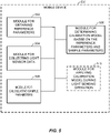
FIG. 5 is a simplified block diagram illustrating several sample aspects of components that may be employed in amobile device 500 configured to support the auto-calibrating of light sensor data as taught herein.Mobile device 500 is one possible implementation ofmobile device 102 ofFIG. 1 represented as a series of interrelated functional modules. - A
module 502 for obtaining one or more reference parameters representative of light sensor data collected by a reference device may correspond at least in some aspects to, for example, anetwork adapter 416 ofFIG. 4 . Amodule 504 for collecting light sensor data from a light sensor included in a mobile device may correspond at least in some aspects to, for example, an auto-calibration unit 418 and/orlight sensor 417 ofFIG. 4 . Amodule 506 for calculating one or more sample parameters of the light sensor data obtained from the light sensor included in themobile device 500 may correspond at in some aspects to, for example, auto-calibration unit 418 and/orprocessing unit 408, ofFIG. 4 . Amodule 508 for determining a calibration model based on the reference parameters and sample parameters may correspond at in some aspects to, for example, auto-calibration unit 418 and/orprocessing unit 408, ofFIG. 4 . Amodule 510 for applying the calibration model to light sensor data during one or more light sensing operations may correspond at in some aspects to, for example, auto-calibration unit 418 and/orprocessing unit 408, ofFIG. 4 . - The functionality of the modules 502-510 of
FIG. 5 may be implemented in various ways consistent with the teachings herein. In some designs, the functionality of these modules 502-510 may be implemented as one or more electrical components. In some designs, the functionality of these modules 502-510 may be implemented as a processing system including one or more processor components. In some designs, the functionality of these modules 502-510 may be implemented using, for example, at least a portion of one or more integrated circuits (e.g., an ASIC). As discussed herein, an integrated circuit may include a processor, software, other related components, or some combination thereof. Thus, the functionality of different modules may be implemented, for example, as different subsets of an integrated circuit, as different subsets of a set of software modules, or a combination thereof. Also, it will be appreciated that a given subset (e.g., of an integrated circuit and/or of a set of software modules) may provide at least a portion of the functionality for more than one module. - In addition, the components and functions represented by
FIG. 5 , as well as other components and functions described herein, may be implemented using any suitable means. Such means also may be implemented, at least in part, using corresponding structure as taught herein. For example, the components described above in conjunction with the "module for" components ofFIG. 5 also may correspond to similarly designated "means for" functionality. Thus, in some aspects, one or more of such means may be implemented using one or more of processor components, integrated circuits, or other suitable structure as taught herein. - While the foregoing disclosure shows illustrative embodiments of the invention, it should be noted that various changes and modifications could be made herein without departing from the scope of the invention as defined by the appended claims. The functions, steps and/or actions of the method claims in accordance with the embodiments of the invention described herein need not be performed in any particular order. Furthermore, although elements of the invention may be described or claimed in the singular, the plural is contemplated unless limitation to the singular is explicitly stated.
Claims (12)
- A method (200) of auto-calibrating light sensor data of a mobile device, the method comprising:sending, by the mobile device, one or more messages to one or more servers in order to obtain one or more reference parameters representative of light sensor data collected by a light sensor of a reference device other than the mobile device;obtaining (202), by the mobile device, one or more reference parameters, from said one or more servers over a network dynamically during an instance of an auto-calibrating process, representative of light sensor data collected by the reference device;collecting (204), by the mobile device, light sensor data from a light sensor included in the mobile device, wherein collecting the light sensor data from the light sensor included in the mobile device includes collecting the light sensor data from the light sensor while the mobile device is located in a first environment, and wherein the light sensor data collected by the reference device is collected while the reference device is located in a second environment that is separate and distinct from the first environment, wherein the second environment is a controlled environment that comprises the reference device subjected to a plurality of controlled lighting conditions to generate the light sensor data collected by the reference device;calculating (206) one or more sample parameters of the light sensor data obtained from the light sensor included in the mobile device;determining (208) a calibration model for auto-calibrating the light sensor data of the light sensor included in the mobile device based on the one or more reference parameters and the one or more sample parameters, wherein determining the calibration model includes calculating a calibration factor based on the one or more reference parameters and the one or more sample parameters using a maximum likelihood estimator; andperforming (210) a light sensing operation, by the mobile device, that includes adjusting the light sensor data collected from the light sensor included in the mobile device based on the calibration factor.
- The method (200) of claim 1, wherein the one or more reference parameters and the one or more sample parameters include one or more statistical values selected from the group consisting of: a mean and a standard deviation of respective light sensor data.
- The method (200) of claim 1, wherein the light sensor of the mobile device comprises at least one of an ambient light sensor, an ultra-violet, UV, sensor, or a red-green-blue, RGB, sensor.
- The method of claim 1, wherein collecting the light sensor data from the light sensor included in the mobile device includes collecting a plurality of light sensor data values over an overnight period of time.
- The method of claim 1, whereincalculating the one or more sample parameters comprises calculating a mean mi and a standard deviation si 2 of the light sensor data collected from the light sensor included in the mobile device,obtaining the one or more reference parameters comprises obtaining a mean µ and a standard deviation σ 2 of the light sensor data collect by the reference device, andcalculating the calibration factor comprises calculating a maximum likelihood estimator Θ i ML of the calibration factor according to:

- The method of claim 1, wherein the light sensing operation includes one or more light sensing operations selected from the group consisting of: indoor/outdoor detection, auto-screen brightness adjustment, sun intensity detection, and white balancing of one or more pictures.
- The method of claim 1, wherein the reference device includes one of: a light sensor device, or a second mobile device including a second light sensor.
- The method of claim 1, further comprising performing the auto-calibrating of the light sensor data independent of any user interaction with the mobile device.
- A mobile device (500) for auto-calibrating light sensor data, the mobile device comprising:a light sensor configured to generate the light sensor data;means for sending, by the mobile device, one or more messages to one or more servers in order to obtain one or more reference parameters representative of light sensor data collected by a light sensor of a reference device other than the mobile device;means (502) for obtaining one or more reference parameters, from said one or more servers over a network dynamically during an instance of an auto-calibrating process, representative of light sensor data collected by the reference device;means (504) for collecting the light sensor data from the light sensor, wherein collecting the light sensor data from the light sensor included in the mobile device includes collecting the light sensor data from the light sensor while the mobile device is located in a first environment, and wherein the light sensor data collected by the reference device is collected while the reference device is located in a second environment that is separate and distinct from the first environment, wherein the second environment is a controlled environment that comprises the reference device subjected to a plurality of controlled lighting conditions to generate the light sensor data collected by the reference device;means (506) for calculating one or more sample parameters of the light sensor data obtained from the light sensor;means (508) for determining a calibration model for auto-calibrating the light sensor data of the light sensor based on the one or more reference parameters and the one or more sample parameters, wherein the means for determining the calibration model includes means for calculating a calibration factor based on the one or more reference parameters and the one or more sample parameters using a maximum likelihood estimator; andmeans (510) for performing a light sensing operation, by the mobile device, that includes means for adjusting the light sensor data collected from the light sensor included in the mobile device based on the calibration factor.
- The mobile device (500) of claim 9, wherein the one or more reference parameters and the one or more sample parameters include one or more statistical values selected from the group consisting of: a mean and a standard deviation of respective light sensor data.
- The mobile device (500) of claim 9, further comprising means for performing the auto-calibrating of the light sensor data independent of any user interaction with the mobile device.
- A non-transitory computer-readable medium including program code stored thereon for auto-calibrating light sensor data, the program code comprising instructions to direct a mobile device (500) to perform the method of any one of claims 1 to 8.
Applications Claiming Priority (2)
| Application Number | Priority Date | Filing Date | Title |
|---|---|---|---|
| US14/843,790 US10145733B2 (en) | 2015-09-02 | 2015-09-02 | Auto-calibrating light sensor data of a mobile device |
| PCT/US2016/045105 WO2017039914A1 (en) | 2015-09-02 | 2016-08-02 | Auto-calibrating light sensor data of a mobile device |
Publications (2)
| Publication Number | Publication Date |
|---|---|
| EP3345089A1 EP3345089A1 (en) | 2018-07-11 |
| EP3345089B1 true EP3345089B1 (en) | 2022-09-21 |
Family
ID=56852384
Family Applications (1)
| Application Number | Title | Priority Date | Filing Date |
|---|---|---|---|
| EP16759895.2A Active EP3345089B1 (en) | 2015-09-02 | 2016-08-02 | Auto-calibrating light sensor data of a mobile device |
Country Status (8)
| Country | Link |
|---|---|
| US (1) | US10145733B2 (en) |
| EP (1) | EP3345089B1 (en) |
| JP (1) | JP6507310B2 (en) |
| KR (1) | KR102044110B1 (en) |
| CN (1) | CN107924312A (en) |
| CA (1) | CA2992746A1 (en) |
| TW (1) | TWI661181B (en) |
| WO (1) | WO2017039914A1 (en) |
Families Citing this family (6)
| Publication number | Priority date | Publication date | Assignee | Title |
|---|---|---|---|---|
| TWI643071B (en) * | 2017-10-18 | 2018-12-01 | 銘祥科技實業股份有限公司 | Artificial intelligence sensing device calibration system and calibration method |
| CN109682408A (en) * | 2017-10-18 | 2019-04-26 | 铭祥科技实业股份有限公司 | Artificial intelligence sensing device corrects system and bearing calibration |
| CN108760042B (en) * | 2018-05-28 | 2020-11-24 | 网易(杭州)网络有限公司 | Optical sensor calibration method and device, mobile device, medium and electronic device |
| CN111081198B (en) * | 2019-11-29 | 2022-12-06 | Tcl移动通信科技(宁波)有限公司 | Data control method, data control device, storage medium and terminal equipment |
| KR20220016713A (en) | 2020-08-03 | 2022-02-10 | 삼성전자주식회사 | Electronic device and method for measuring illuminance |
| CN112433694B (en) * | 2020-11-23 | 2023-12-26 | 惠州Tcl移动通信有限公司 | Light intensity adjusting method and device, storage medium and mobile terminal |
Family Cites Families (22)
| Publication number | Priority date | Publication date | Assignee | Title |
|---|---|---|---|---|
| JP2009010983A (en) | 1996-02-26 | 2009-01-15 | Richard A Holub | Method of associating different image display devices, color error detection method, and color measurement device |
| US6437823B1 (en) * | 1999-04-30 | 2002-08-20 | Microsoft Corporation | Method and system for calibrating digital cameras |
| NZ504536A (en) * | 2000-05-12 | 2001-11-30 | Agres Ltd | Remote analysis and calibration of near infra-red spectrophotometer data |
| JP4122996B2 (en) * | 2002-08-27 | 2008-07-23 | 松下電工株式会社 | Environmental state quantity measurement and monitoring system |
| US6985834B2 (en) | 2003-12-16 | 2006-01-10 | Agilent Technologies, Inc. | Methods and system for comparing data values across multiple platforms |
| JP2009002661A (en) * | 2007-06-19 | 2009-01-08 | Seiko Epson Corp | Sensing circuit, light detection circuit, display, and electronic equipment |
| JP2010164355A (en) * | 2009-01-14 | 2010-07-29 | Topcon Corp | Stimulus-value direct reading instrument |
| US9412164B2 (en) * | 2010-05-25 | 2016-08-09 | Hewlett-Packard Development Company, L.P. | Apparatus and methods for imaging system calibration |
| JP2012118850A (en) * | 2010-12-02 | 2012-06-21 | Nec Casio Mobile Communications Ltd | Terminal device, execution method and program of automatic calibration |
| WO2012143814A1 (en) * | 2011-04-19 | 2012-10-26 | Koninklijke Philips Electronics N.V. | Oln light change/optimization system |
| US20120274799A1 (en) * | 2011-04-28 | 2012-11-01 | Yu-Wei Wang | Calibrating image sensors |
| EP2696561B1 (en) | 2011-04-29 | 2017-06-07 | Huawei Device Co., Ltd. | Method for controlling light-emitting device in terminal equipment, apparatus thereof and terminal equipment |
| US10948289B2 (en) | 2011-11-03 | 2021-03-16 | Sony Corporation | System and method for calibrating sensors across loosely coupled consumer electronic devices |
| US9625490B2 (en) * | 2011-12-01 | 2017-04-18 | Qualcomm Incorporated | Mitigating the effect of a change in sensor calibration parameters |
| US8525752B2 (en) | 2011-12-13 | 2013-09-03 | International Business Machines Corporation | System and method for automatically adjusting electronic display settings |
| DE102012107214A1 (en) | 2012-08-07 | 2014-02-13 | Endress + Hauser Conducta Gesellschaft für Mess- und Regeltechnik mbH + Co. KG | Method for calibrating a sensor for turbidity measurement |
| US9129548B2 (en) | 2012-11-15 | 2015-09-08 | Apple Inc. | Ambient light sensors with infrared compensation |
| CN104320641B (en) | 2013-03-13 | 2017-04-12 | 豪威科技股份有限公司 | Apparatus and method for automated self-training of white balance by electronic cameras |
| JP6273806B2 (en) * | 2013-12-03 | 2018-02-07 | 富士通株式会社 | Apparatus and method for generating calibration coefficients for optical signal-to-noise ratio monitoring |
| US9071744B1 (en) * | 2014-06-16 | 2015-06-30 | Amazon Technologies, Inc. | Mobile device flash calibration |
| KR102361025B1 (en) * | 2014-07-31 | 2022-02-08 | 삼성전자주식회사 | Wearable glasses and method for displaying image therethrough |
| KR20160016555A (en) * | 2014-07-31 | 2016-02-15 | 삼성전자주식회사 | Method for controlling a terminal and the terminal thereof |
-
2015
- 2015-09-02 US US14/843,790 patent/US10145733B2/en active Active
-
2016
- 2016-08-02 KR KR1020187009002A patent/KR102044110B1/en active IP Right Grant
- 2016-08-02 JP JP2018511024A patent/JP6507310B2/en not_active Expired - Fee Related
- 2016-08-02 CN CN201680048564.XA patent/CN107924312A/en active Pending
- 2016-08-02 TW TW105124490A patent/TWI661181B/en not_active IP Right Cessation
- 2016-08-02 EP EP16759895.2A patent/EP3345089B1/en active Active
- 2016-08-02 WO PCT/US2016/045105 patent/WO2017039914A1/en active Search and Examination
- 2016-08-02 CA CA2992746A patent/CA2992746A1/en not_active Abandoned
Also Published As
| Publication number | Publication date |
|---|---|
| JP2018532988A (en) | 2018-11-08 |
| TWI661181B (en) | 2019-06-01 |
| JP6507310B2 (en) | 2019-04-24 |
| KR102044110B1 (en) | 2019-11-12 |
| CN107924312A (en) | 2018-04-17 |
| TW201719125A (en) | 2017-06-01 |
| WO2017039914A1 (en) | 2017-03-09 |
| KR20180048885A (en) | 2018-05-10 |
| US20170059401A1 (en) | 2017-03-02 |
| US10145733B2 (en) | 2018-12-04 |
| EP3345089A1 (en) | 2018-07-11 |
| CA2992746A1 (en) | 2017-03-09 |
Similar Documents
| Publication | Publication Date | Title |
|---|---|---|
| EP3345089B1 (en) | Auto-calibrating light sensor data of a mobile device | |
| US10503250B2 (en) | System and method for setting display brightness of display of electronic device | |
| KR102570305B1 (en) | Electronic apparatus and controlling method thereof | |
| CN109005457B (en) | Black screen detection method and device, computer equipment and storage medium | |
| KR20190139062A (en) | Electronic device for providing customized quality image and method for controlling thereof | |
| US10261393B2 (en) | Method for controlling infrared illuminator and related image-recording device | |
| WO2015057493A1 (en) | Refocusable images | |
| US20150356081A1 (en) | Advanced camera management function | |
| CN112333898A (en) | Lamp brightness adjusting method and device, lamp and storage medium | |
| US11595585B2 (en) | Exposure change control in low light environments | |
| US20190364186A1 (en) | Image processing method and electronic device supporting same | |
| US9912846B2 (en) | Obtaining calibration data of a camera | |
| US20150194091A1 (en) | Method and device for ambient light estimation | |
| US20170150051A1 (en) | Information processing apparatus, information processing method, and program | |
| KR20170014919A (en) | Electronic apparatus and method for detecting skin condition in electronic apparatus | |
| US20170163877A1 (en) | Method and electronic device for photo shooting in backlighting scene | |
| KR20160134428A (en) | Electronic device for processing image and method for controlling thereof | |
| CN111742556B (en) | Electronic device for sharing real-time content data | |
| US11589021B1 (en) | Color correction for video communications using display content color information | |
| CN111164508B (en) | System and method for improved camera flash | |
| US20190180679A1 (en) | Display calibration to minimize image retention | |
| CN105807541B (en) | Imaging method and imaging device | |
| WO2020062218A1 (en) | Control method for image capture device and image capture device | |
| KR20180013400A (en) | Image processing method and electronic device supporting the same |
Legal Events
| Date | Code | Title | Description |
|---|---|---|---|
| STAA | Information on the status of an ep patent application or granted ep patent |
Free format text: STATUS: THE INTERNATIONAL PUBLICATION HAS BEEN MADE |
|
| PUAI | Public reference made under article 153(3) epc to a published international application that has entered the european phase |
Free format text: ORIGINAL CODE: 0009012 |
|
| STAA | Information on the status of an ep patent application or granted ep patent |
Free format text: STATUS: REQUEST FOR EXAMINATION WAS MADE |
|
| 17P | Request for examination filed |
Effective date: 20180116 |
|
| AK | Designated contracting states |
Kind code of ref document: A1 Designated state(s): AL AT BE BG CH CY CZ DE DK EE ES FI FR GB GR HR HU IE IS IT LI LT LU LV MC MK MT NL NO PL PT RO RS SE SI SK SM TR |
|
| AX | Request for extension of the european patent |
Extension state: BA ME |
|
| DAV | Request for validation of the european patent (deleted) | ||
| DAX | Request for extension of the european patent (deleted) | ||
| STAA | Information on the status of an ep patent application or granted ep patent |
Free format text: STATUS: EXAMINATION IS IN PROGRESS |
|
| 17Q | First examination report despatched |
Effective date: 20200629 |
|
| STAA | Information on the status of an ep patent application or granted ep patent |
Free format text: STATUS: EXAMINATION IS IN PROGRESS |
|
| REG | Reference to a national code |
Ref country code: DE Ref legal event code: R079 Ref document number: 602016075162 Country of ref document: DE Free format text: PREVIOUS MAIN CLASS: G06F0009440000 Ipc: G06F0009440100 |
|
| GRAP | Despatch of communication of intention to grant a patent |
Free format text: ORIGINAL CODE: EPIDOSNIGR1 |
|
| STAA | Information on the status of an ep patent application or granted ep patent |
Free format text: STATUS: GRANT OF PATENT IS INTENDED |
|
| RIC1 | Information provided on ipc code assigned before grant |
Ipc: H04M 1/72454 20210101ALI20220505BHEP Ipc: H04M 1/22 20060101ALI20220505BHEP Ipc: G06F 9/4401 20180101AFI20220505BHEP |
|
| INTG | Intention to grant announced |
Effective date: 20220525 |
|
| GRAS | Grant fee paid |
Free format text: ORIGINAL CODE: EPIDOSNIGR3 |
|
| GRAA | (expected) grant |
Free format text: ORIGINAL CODE: 0009210 |
|
| STAA | Information on the status of an ep patent application or granted ep patent |
Free format text: STATUS: THE PATENT HAS BEEN GRANTED |
|
| AK | Designated contracting states |
Kind code of ref document: B1 Designated state(s): AL AT BE BG CH CY CZ DE DK EE ES FI FR GB GR HR HU IE IS IT LI LT LU LV MC MK MT NL NO PL PT RO RS SE SI SK SM TR |
|
| REG | Reference to a national code |
Ref country code: GB Ref legal event code: FG4D |
|
| REG | Reference to a national code |
Ref country code: CH Ref legal event code: EP |
|
| REG | Reference to a national code |
Ref country code: DE Ref legal event code: R096 Ref document number: 602016075162 Country of ref document: DE |
|
| REG | Reference to a national code |
Ref country code: IE Ref legal event code: FG4D |
|
| REG | Reference to a national code |
Ref country code: AT Ref legal event code: REF Ref document number: 1520281 Country of ref document: AT Kind code of ref document: T Effective date: 20221015 |
|
| REG | Reference to a national code |
Ref country code: LT Ref legal event code: MG9D |
|
| REG | Reference to a national code |
Ref country code: NL Ref legal event code: MP Effective date: 20220921 |
|
| PG25 | Lapsed in a contracting state [announced via postgrant information from national office to epo] |
Ref country code: SE Free format text: LAPSE BECAUSE OF FAILURE TO SUBMIT A TRANSLATION OF THE DESCRIPTION OR TO PAY THE FEE WITHIN THE PRESCRIBED TIME-LIMIT Effective date: 20220921 Ref country code: RS Free format text: LAPSE BECAUSE OF FAILURE TO SUBMIT A TRANSLATION OF THE DESCRIPTION OR TO PAY THE FEE WITHIN THE PRESCRIBED TIME-LIMIT Effective date: 20220921 Ref country code: NO Free format text: LAPSE BECAUSE OF FAILURE TO SUBMIT A TRANSLATION OF THE DESCRIPTION OR TO PAY THE FEE WITHIN THE PRESCRIBED TIME-LIMIT Effective date: 20221221 Ref country code: LV Free format text: LAPSE BECAUSE OF FAILURE TO SUBMIT A TRANSLATION OF THE DESCRIPTION OR TO PAY THE FEE WITHIN THE PRESCRIBED TIME-LIMIT Effective date: 20220921 Ref country code: LT Free format text: LAPSE BECAUSE OF FAILURE TO SUBMIT A TRANSLATION OF THE DESCRIPTION OR TO PAY THE FEE WITHIN THE PRESCRIBED TIME-LIMIT Effective date: 20220921 Ref country code: FI Free format text: LAPSE BECAUSE OF FAILURE TO SUBMIT A TRANSLATION OF THE DESCRIPTION OR TO PAY THE FEE WITHIN THE PRESCRIBED TIME-LIMIT Effective date: 20220921 |
|
| REG | Reference to a national code |
Ref country code: AT Ref legal event code: MK05 Ref document number: 1520281 Country of ref document: AT Kind code of ref document: T Effective date: 20220921 |
|
| PG25 | Lapsed in a contracting state [announced via postgrant information from national office to epo] |
Ref country code: HR Free format text: LAPSE BECAUSE OF FAILURE TO SUBMIT A TRANSLATION OF THE DESCRIPTION OR TO PAY THE FEE WITHIN THE PRESCRIBED TIME-LIMIT Effective date: 20220921 Ref country code: GR Free format text: LAPSE BECAUSE OF FAILURE TO SUBMIT A TRANSLATION OF THE DESCRIPTION OR TO PAY THE FEE WITHIN THE PRESCRIBED TIME-LIMIT Effective date: 20221222 |
|
| PG25 | Lapsed in a contracting state [announced via postgrant information from national office to epo] |
Ref country code: SM Free format text: LAPSE BECAUSE OF FAILURE TO SUBMIT A TRANSLATION OF THE DESCRIPTION OR TO PAY THE FEE WITHIN THE PRESCRIBED TIME-LIMIT Effective date: 20220921 Ref country code: RO Free format text: LAPSE BECAUSE OF FAILURE TO SUBMIT A TRANSLATION OF THE DESCRIPTION OR TO PAY THE FEE WITHIN THE PRESCRIBED TIME-LIMIT Effective date: 20220921 Ref country code: PT Free format text: LAPSE BECAUSE OF FAILURE TO SUBMIT A TRANSLATION OF THE DESCRIPTION OR TO PAY THE FEE WITHIN THE PRESCRIBED TIME-LIMIT Effective date: 20230123 Ref country code: ES Free format text: LAPSE BECAUSE OF FAILURE TO SUBMIT A TRANSLATION OF THE DESCRIPTION OR TO PAY THE FEE WITHIN THE PRESCRIBED TIME-LIMIT Effective date: 20220921 Ref country code: CZ Free format text: LAPSE BECAUSE OF FAILURE TO SUBMIT A TRANSLATION OF THE DESCRIPTION OR TO PAY THE FEE WITHIN THE PRESCRIBED TIME-LIMIT Effective date: 20220921 Ref country code: AT Free format text: LAPSE BECAUSE OF FAILURE TO SUBMIT A TRANSLATION OF THE DESCRIPTION OR TO PAY THE FEE WITHIN THE PRESCRIBED TIME-LIMIT Effective date: 20220921 |
|
| PG25 | Lapsed in a contracting state [announced via postgrant information from national office to epo] |
Ref country code: SK Free format text: LAPSE BECAUSE OF FAILURE TO SUBMIT A TRANSLATION OF THE DESCRIPTION OR TO PAY THE FEE WITHIN THE PRESCRIBED TIME-LIMIT Effective date: 20220921 Ref country code: PL Free format text: LAPSE BECAUSE OF FAILURE TO SUBMIT A TRANSLATION OF THE DESCRIPTION OR TO PAY THE FEE WITHIN THE PRESCRIBED TIME-LIMIT Effective date: 20220921 Ref country code: IS Free format text: LAPSE BECAUSE OF FAILURE TO SUBMIT A TRANSLATION OF THE DESCRIPTION OR TO PAY THE FEE WITHIN THE PRESCRIBED TIME-LIMIT Effective date: 20230121 Ref country code: EE Free format text: LAPSE BECAUSE OF FAILURE TO SUBMIT A TRANSLATION OF THE DESCRIPTION OR TO PAY THE FEE WITHIN THE PRESCRIBED TIME-LIMIT Effective date: 20220921 |
|
| REG | Reference to a national code |
Ref country code: DE Ref legal event code: R097 Ref document number: 602016075162 Country of ref document: DE |
|
| PG25 | Lapsed in a contracting state [announced via postgrant information from national office to epo] |
Ref country code: NL Free format text: LAPSE BECAUSE OF FAILURE TO SUBMIT A TRANSLATION OF THE DESCRIPTION OR TO PAY THE FEE WITHIN THE PRESCRIBED TIME-LIMIT Effective date: 20220921 Ref country code: AL Free format text: LAPSE BECAUSE OF FAILURE TO SUBMIT A TRANSLATION OF THE DESCRIPTION OR TO PAY THE FEE WITHIN THE PRESCRIBED TIME-LIMIT Effective date: 20220921 |
|
| PLBE | No opposition filed within time limit |
Free format text: ORIGINAL CODE: 0009261 |
|
| STAA | Information on the status of an ep patent application or granted ep patent |
Free format text: STATUS: NO OPPOSITION FILED WITHIN TIME LIMIT |
|
| PG25 | Lapsed in a contracting state [announced via postgrant information from national office to epo] |
Ref country code: DK Free format text: LAPSE BECAUSE OF FAILURE TO SUBMIT A TRANSLATION OF THE DESCRIPTION OR TO PAY THE FEE WITHIN THE PRESCRIBED TIME-LIMIT Effective date: 20220921 |
|
| 26N | No opposition filed |
Effective date: 20230622 |
|
| PG25 | Lapsed in a contracting state [announced via postgrant information from national office to epo] |
Ref country code: SI Free format text: LAPSE BECAUSE OF FAILURE TO SUBMIT A TRANSLATION OF THE DESCRIPTION OR TO PAY THE FEE WITHIN THE PRESCRIBED TIME-LIMIT Effective date: 20220921 |
|
| PGFP | Annual fee paid to national office [announced via postgrant information from national office to epo] |
Ref country code: GB Payment date: 20230712 Year of fee payment: 8 |
|
| PGFP | Annual fee paid to national office [announced via postgrant information from national office to epo] |
Ref country code: FR Payment date: 20230710 Year of fee payment: 8 Ref country code: DE Payment date: 20230711 Year of fee payment: 8 |
|
| PG25 | Lapsed in a contracting state [announced via postgrant information from national office to epo] |
Ref country code: MC Free format text: LAPSE BECAUSE OF FAILURE TO SUBMIT A TRANSLATION OF THE DESCRIPTION OR TO PAY THE FEE WITHIN THE PRESCRIBED TIME-LIMIT Effective date: 20220921 |
|
| REG | Reference to a national code |
Ref country code: CH Ref legal event code: PL |
|
| PG25 | Lapsed in a contracting state [announced via postgrant information from national office to epo] |
Ref country code: MC Free format text: LAPSE BECAUSE OF FAILURE TO SUBMIT A TRANSLATION OF THE DESCRIPTION OR TO PAY THE FEE WITHIN THE PRESCRIBED TIME-LIMIT Effective date: 20220921 |
|
| PG25 | Lapsed in a contracting state [announced via postgrant information from national office to epo] |
Ref country code: LU Free format text: LAPSE BECAUSE OF NON-PAYMENT OF DUE FEES Effective date: 20230802 |
|
| PG25 | Lapsed in a contracting state [announced via postgrant information from national office to epo] |
Ref country code: LU Free format text: LAPSE BECAUSE OF NON-PAYMENT OF DUE FEES Effective date: 20230802 Ref country code: CH Free format text: LAPSE BECAUSE OF NON-PAYMENT OF DUE FEES Effective date: 20230831 |
|
| REG | Reference to a national code |
Ref country code: BE Ref legal event code: MM Effective date: 20230831 |
|
| REG | Reference to a national code |
Ref country code: IE Ref legal event code: MM4A |