EP3344559B1 - Beverage can closure, and can unit consisting of a beverage can and a closure - Google Patents
Beverage can closure, and can unit consisting of a beverage can and a closure Download PDFInfo
- Publication number
- EP3344559B1 EP3344559B1 EP16724888.9A EP16724888A EP3344559B1 EP 3344559 B1 EP3344559 B1 EP 3344559B1 EP 16724888 A EP16724888 A EP 16724888A EP 3344559 B1 EP3344559 B1 EP 3344559B1
- Authority
- EP
- European Patent Office
- Prior art keywords
- beverage
- closure
- retaining ring
- longitudinal
- base body
- Prior art date
- Legal status (The legal status is an assumption and is not a legal conclusion. Google has not performed a legal analysis and makes no representation as to the accuracy of the status listed.)
- Active
Links
- 235000013361 beverage Nutrition 0.000 title claims description 123
- 238000007789 sealing Methods 0.000 claims description 56
- 230000035622 drinking Effects 0.000 claims description 36
- 239000003566 sealing material Substances 0.000 claims description 5
- 230000000694 effects Effects 0.000 description 10
- 230000007246 mechanism Effects 0.000 description 6
- 230000000295 complement effect Effects 0.000 description 4
- 239000000463 material Substances 0.000 description 4
- 239000004033 plastic Substances 0.000 description 4
- 238000003825 pressing Methods 0.000 description 3
- 241000238631 Hexapoda Species 0.000 description 2
- XAGFODPZIPBFFR-UHFFFAOYSA-N aluminium Chemical compound [Al] XAGFODPZIPBFFR-UHFFFAOYSA-N 0.000 description 2
- 229910052782 aluminium Inorganic materials 0.000 description 2
- 238000004519 manufacturing process Methods 0.000 description 2
- 238000000034 method Methods 0.000 description 2
- 230000008569 process Effects 0.000 description 2
- 230000000284 resting effect Effects 0.000 description 2
- 239000004743 Polypropylene Substances 0.000 description 1
- 238000013459 approach Methods 0.000 description 1
- 230000009286 beneficial effect Effects 0.000 description 1
- 235000014171 carbonated beverage Nutrition 0.000 description 1
- 230000007423 decrease Effects 0.000 description 1
- 230000001066 destructive effect Effects 0.000 description 1
- 230000005489 elastic deformation Effects 0.000 description 1
- 239000013013 elastic material Substances 0.000 description 1
- 238000004049 embossing Methods 0.000 description 1
- 230000007613 environmental effect Effects 0.000 description 1
- 239000000945 filler Substances 0.000 description 1
- 230000006872 improvement Effects 0.000 description 1
- 239000007788 liquid Substances 0.000 description 1
- -1 polypropylene Polymers 0.000 description 1
- 229920001155 polypropylene Polymers 0.000 description 1
- 238000004080 punching Methods 0.000 description 1
- 238000005507 spraying Methods 0.000 description 1
- 230000008719 thickening Effects 0.000 description 1
- 230000007704 transition Effects 0.000 description 1
- 239000002699 waste material Substances 0.000 description 1
- 238000003466 welding Methods 0.000 description 1
Images

Classifications
-
- B—PERFORMING OPERATIONS; TRANSPORTING
- B65—CONVEYING; PACKING; STORING; HANDLING THIN OR FILAMENTARY MATERIAL
- B65D—CONTAINERS FOR STORAGE OR TRANSPORT OF ARTICLES OR MATERIALS, e.g. BAGS, BARRELS, BOTTLES, BOXES, CANS, CARTONS, CRATES, DRUMS, JARS, TANKS, HOPPERS, FORWARDING CONTAINERS; ACCESSORIES, CLOSURES, OR FITTINGS THEREFOR; PACKAGING ELEMENTS; PACKAGES
- B65D51/00—Closures not otherwise provided for
- B65D51/007—Separate closure devices for reclosing opened cans or tins, e.g. beer cans
-
- B—PERFORMING OPERATIONS; TRANSPORTING
- B65—CONVEYING; PACKING; STORING; HANDLING THIN OR FILAMENTARY MATERIAL
- B65D—CONTAINERS FOR STORAGE OR TRANSPORT OF ARTICLES OR MATERIALS, e.g. BAGS, BARRELS, BOTTLES, BOXES, CANS, CARTONS, CRATES, DRUMS, JARS, TANKS, HOPPERS, FORWARDING CONTAINERS; ACCESSORIES, CLOSURES, OR FITTINGS THEREFOR; PACKAGING ELEMENTS; PACKAGES
- B65D51/00—Closures not otherwise provided for
- B65D51/18—Arrangements of closures with protective outer cap-like covers or of two or more co-operating closures
- B65D51/20—Caps, lids, or covers co-operating with an inner closure arranged to be opened by piercing, cutting, or tearing
-
- B—PERFORMING OPERATIONS; TRANSPORTING
- B65—CONVEYING; PACKING; STORING; HANDLING THIN OR FILAMENTARY MATERIAL
- B65D—CONTAINERS FOR STORAGE OR TRANSPORT OF ARTICLES OR MATERIALS, e.g. BAGS, BARRELS, BOTTLES, BOXES, CANS, CARTONS, CRATES, DRUMS, JARS, TANKS, HOPPERS, FORWARDING CONTAINERS; ACCESSORIES, CLOSURES, OR FITTINGS THEREFOR; PACKAGING ELEMENTS; PACKAGES
- B65D2251/00—Details relating to container closures
- B65D2251/0003—Two or more closures
- B65D2251/0006—Upper closure
- B65D2251/0025—Upper closure of the 47-type
-
- B—PERFORMING OPERATIONS; TRANSPORTING
- B65—CONVEYING; PACKING; STORING; HANDLING THIN OR FILAMENTARY MATERIAL
- B65D—CONTAINERS FOR STORAGE OR TRANSPORT OF ARTICLES OR MATERIALS, e.g. BAGS, BARRELS, BOTTLES, BOXES, CANS, CARTONS, CRATES, DRUMS, JARS, TANKS, HOPPERS, FORWARDING CONTAINERS; ACCESSORIES, CLOSURES, OR FITTINGS THEREFOR; PACKAGING ELEMENTS; PACKAGES
- B65D2251/00—Details relating to container closures
- B65D2251/0003—Two or more closures
- B65D2251/0068—Lower closure
- B65D2251/0071—Lower closure of the 17-type
Definitions
- the invention relates to a resealable beverage can closure for attaching to a beverage can and a can unit consisting of a beverage can and an attached beverage can closure.
- Beverage cans with a disposable closure are well known. Such cans have a jacket and a base that merge into one another and are formed by deep drawing. The top of the can is formed by a separately manufactured end wall that is welded to the rest of the can. In this end wall, which is usually made of aluminum like the rest of the can, a drinking opening is perforated by punching. This drinking opening can then be opened once. There are various opening mechanisms for opening, but the section of wall around which the perforation runs is usually pushed in, exposing the opening. In the case of beverage cans, a lever attached to the front wall, also called a locking ring or pulltab, has become established.
- Beverage cans essentially have a standardized geometry, with the casing always being cylindrical over almost the entire axial height and a closed, circumferential, ring-shaped bulge on the bottom of the can, over which a ring-shaped base is formed.
- This ring-shaped bulge is important for stackability, because the bulge is located on the inside of an upwardly protruding upper edge of the can underneath, which holds the can standing on top of it laterally.
- the casing also has a circumferential, lateral, radially outward-open ring groove below its previously mentioned upper edge in the edge area to the front wall (welding area).
- a beverage can closure is known in which a bent wire ring that does not completely run around the can snaps into the ring groove on the can side.
- Two wire sections protrude from the ring section at a clear distance from the can opening inwards and merge into one another in a connecting web on the narrow edge of the can opening.
- the connecting web forms a pivot axis for a lid that has a locking tab that snaps into the ring groove to close the can.
- beverage manufacturers are often not interested in resealability of the can because, on the one hand, the closing mechanism makes the can more expensive and thus reduces profits and, on the other hand, overall consumption decreases.
- the object of the invention is therefore to create a resealable beverage can closure and a can unit consisting of a beverage can and a beverage can closure, through which the drinking opening on the can side, which only needs to be opened once, can be resealed.
- the beverage can closure according to the invention should be easy to manufacture and, above all, should seal reliably against the front wall of the can.
- a resealable beverage can closure according to claim 1, which can be attached to a beverage can and has a base body that can be fastened to the can side and a lid attached to the base body and movable relative to the base body for reversibly resealing the beverage can.
- the base body has a circumferential retaining ring for locking, i.e. snapping, into the annular groove in the edge area of the jacket of the can as well as longitudinal webs connected in one piece with the retaining ring and adjacent to a central opening in the base body. to rest against the side wall to the side of the drinking opening.
- the central opening is designed around the drinking opening and exposes it when the beverage can closure is opened, either for the first time opening the drinking opening in the front wall or after opening to empty the beverage can.
- the longitudinal webs run transversely to the retaining ring and essentially connect opposite holding sections to one another, with at least one free space between the longitudinal webs and the adjacent sections of the retaining ring. This free space is, so to speak, a hole in the base body.
- the central opening is located between the longitudinal webs. On the other side of the respective longitudinal webs there is then the previously mentioned free space, which ensures that the retaining ring is exposed in this area and is not coupled to an upper wall section of the base body.
- the retaining ring Since the retaining ring thus has clamp-like sections exposed in the area of the free spaces, the retaining ring is significantly more flexible in the circumferential direction than in embodiments in which the retaining ring merges in one piece all the way around into an upper wall of the base body that completely covers the front wall. Due to this greater flexibility of the retaining ring, it can be more easily placed on the beverage can and, above all, given a larger undersize to the can's outer geometry. In addition, this undersize in the embodiment according to the invention has less influence on the important sealing surfaces, which in the present case are formed by the longitudinal webs.
- the lid has adjacent longitudinal ribs on its underside facing the base body, whereby each longitudinal rib is assigned to a longitudinal web and, when the beverage can closure is closed, cooperates with the longitudinal web to form a seal, preferably resting against it.
- a relatively narrow pressing surface or pressing lip is created via these longitudinal ribs, which creates a better sealing effect than a wide rib. Since the sealing effect is always created by plastic deformation of one or both of the sections or parts lying on top of one another and on top of one another, a higher elastic deformation of the sections or parts pressed against one another can be achieved with the same contact force and a smaller contact surface formed by a narrower longitudinal rib, which is beneficial for the seal.
- the longitudinal webs can be further stretched elastically in order to adapt to the end wall, which bulges out again, and to press against it.
- At least over 35%, in particular over at least 45%, of the circumferential length of the retaining ring are adjacent to free spaces, which means that in these sections the retaining ring is actually only designed as a clamp section and not upwards over the upper one Edge merges into a front section of the base body.
- transverse webs connecting the longitudinal webs are provided in the area of the ends of the longitudinal webs.
- the longitudinal and transverse webs together form a closed sealing web that surrounds the drinking opening and rests against the end wall, which in turn surrounds the central opening or also defines the central opening.
- the sealing effect between the beverage can closure and the beverage can is therefore achieved exclusively through contact on the end wall of the can.
- At least one crossbar can merge into the retaining ring in one piece along its entire side edge via an intermediate section, so that in this area a section (intermediate section) of the base body runs from the retaining ring over the upper edge of the can to the part of the closure that is above the The front wall is located. In this case, this part is the crossbar.
- the beverage can closure is consequently stiffened, which allows other functions that require a rigid geometry to be provided here.
- At least one crossbar along its side edge may merge into the retaining ring in one piece only in sections through connecting ribs and for a gap to be present between the connecting ribs.
- This variant increases the circumferential length in which the retaining ring is actually only designed as a clamp section.
- the sealing web can be designed to be resilient relative to the retaining ring perpendicular to the plane defined by the retaining ring, so that the sealing web presses against the end wall with pre-tension when the drinks can is closed and the end wall is curved outwards, and when the drinks can is open and the end wall is essentially flat.
- the lower edge of the retaining ring lies in one plane or, in the assembled position, defines a plane through the ring groove. Since the retaining ring cannot be moved resiliently perpendicular to the end wall when it is snapped onto the drinks can, the sealing web is designed to be movable relative to it.
- the longitudinal webs and/or the transverse webs can be curved towards the underside. This means that in the initial state the longitudinal webs bulge towards the front wall in order to create a spring effect, similar to a pre-tensioned leaf spring, and to increase the pressure on the front wall where it springs back most when the can is opened.
- the preferred embodiment of the invention provides that the sealing web lies completely below the upper edge of the can onto which the beverage can closure is snapped. It lies in the recess that is formed between the upwardly projecting upper edge of the can and its end wall. This ensures that when stacking cans with equipped with the beverage can closure according to the invention, there is no significant increase in the stack height.
- the lid can be connected to the base body via a pivot bearing, in particular a film hinge, so that the lid and base body form a one-piece unit.
- the preferred embodiment of the invention naturally provides that the beverage can closure according to the invention is made entirely of plastic.
- the pivot bearing can be provided in the area of the gap defined between the connecting ribs of the crosspiece and the retaining ring. This also creates more space for the part of the cover that is close to the film hinge.
- the lid can also be detachably held on the base body in the closed position of the beverage can closure via a snap-in connection, i.e. it is easy to open and close.
- a locking geometry of the latching body provided on the base body, which interacts with a corresponding locking geometry on the lid, can be formed on the intermediate section, which merges into a crosspiece and the retaining ring.
- this is of course provided on the crosspiece that is connected to the retaining ring in one piece along its entire side edge via the intermediate section and thus forms a very rigid section of the beverage can closure.
- the locking geometry of the latching body can also be formed on the base body in the area of a longitudinal web, in particular on one of the two connecting ribs with which each longitudinal web is connected to the retaining ring. Preferably in the area of the sides of the longitudinal webs facing away from the film hinge.
- the lid has on its underside a closed circumferential pressure surface, preferably defined by a circumferential rib, which cooperates sealingly with the sealing web when the closure is closed, preferably rests in a closed circumferential manner on the sealing web.
- the base body can have an elastic seal that runs closed around the central opening on its underside facing the front wall and/or on an upper side facing the lid.
- the seal is made of a softer and more elastic material than the rest of the base body.
- a simple manufacture of the beverage can closure according to the invention results from the fact that the beverage can closure is a 2-component injection-molded part, with one component forming the base body and the lid and the other component forming the seal or seals.
- At least the longitudinal webs, and preferably also the transverse webs can have holes through them from the top to the bottom.
- a particularly effective seal is achieved by a side sealing surface running around the central opening, which is part of the seal and thus of the sealing web and which extends essentially perpendicular to the central opening.
- This side sealing surface can interact with the contact surfaces, in particular the sides of the rib of the lid, in order to tightly close the beverage can closure.
- the seal can also have a base that is provided between the side sealing surface and the central opening. This creates a further sealing surface against which the contact surface can rest, thereby further improving the sealing effect of the seal.
- the base can also be provided with a groove to improve the fit of the cover on the seal, whereby parts of the side surface can limit the groove on one side.
- the contact surface can be sealed against the Partially abut the side sealing wall, in particular partially abut the side of the side sealing wall facing the central opening.
- the seal has at least one extension which extends further downwards, at least in sections, below at least one of the longitudinal and/or transverse webs, away from this longitudinal and/or transverse web, wherein the extension is designed such that it can engage in the recess of the front wall in a sealing manner.
- the extension is designed, for example, in the sections of the seal which are arranged above the recess when the beverage can closure is in place.
- the contour of the extension is preferably complementary to the contour of the recess, in particular complementary to the wall of the recess on the drinking opening side, so that the seal can also adapt to the front wall in the region of the recess and seal it.
- the beverage can closure can have a recess formed at least in circular segment sections on its top side when closed. This recess serves to accommodate the previously mentioned ring-shaped bulge of the can to form the base. This holds the can placed on the closure according to the invention laterally.
- predetermined, projecting contact points can be formed to support the bulge, so that the can stacked thereon only rests on the closure according to the invention at a few predefined points. This is also for hygiene purposes, as the area that may be contacted by the user's mouth should not have been previously contacted by an attached can.
- the central opening in the base body should be large enough so that the drinking opening and a locking ring provided on the front wall of the can for opening the drinking opening lie completely in the central opening.
- the central opening therefore ensures that both the drinking opening and the opening mechanism on the can are accessible.
- the central opening has an elongated shape, with the opening being wider at one longitudinal end than at the opposite longitudinal end.
- the longitudinal webs therefore run essentially obliquely towards or away from each other.
- the lid can be curved from the bottom to the top to accommodate an activated locking ring when the beverage can closure is closed. These locking rings are pulled up and bent over when opened. For environmental reasons, the locking rings usually remain attached to the front wall and thus protrude further upwards than when not activated. The lid shaped in this way also closes securely when the locking ring is still attached to the front wall but has already been activated.
- the upper end of the retaining ring merges into a section that extends over the upper edge of the can that connects the jacket and the front wall in the direction of the front wall, thus covering the upper edge of the can in sections.
- This section forms a drinking rim.
- the drinking rim should be located on the section of the retaining ring that is closest to the drinking opening.
- a protruding lip can be provided on the lid. This lip covers the drinking rim when the beverage can closure is closed and exposes it when the beverage can closure is open.
- the invention further relates to a can unit made from a beverage can of the aforementioned type, which has a casing and a front wall which has a drinking opening closed by a disposable closure, wherein the casing has a circumferential lateral annular groove in the area of the front wall.
- the can unit according to the invention comprises a beverage can closure according to the invention.
- This beverage can closure can be removed from the beverage can without causing any damage and can therefore be reused on a can that is still full.
- top and bottom refer to the state in which the beverage can closure is placed on a beverage can and the Beverage can stands horizontally on a surface with the drinking opening facing upwards.
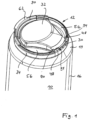
- a can unit consisting of a conventional beverage can 10 made of aluminum and a resealable, separately manufactured beverage can closure 12 attached to the beverage can 10.
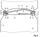
- the beverage can 10 essentially consists of a base 14, which is Figure 5 can be seen using an identical beverage can 10 placed on the can unit, a one-piece, predominantly circular-cylindrical shell 16 and a front wall 18, which is recessed.
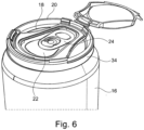
- the shell surface 16 usually has a truncated cone-shaped section 19 towards its upper end in beverage cans, to which an upwardly circumferential edge region with an upper edge 20 of the can is connected (see Figure 6 ), via which the casing 16 and the front wall 18 are connected to one another.
- the front wall 18 is recessed opposite the upper edge 20.
- a drinking opening 22 is predefined by an embossing, which can be closed or opened once by a disposable closure with an opening mechanism, for example a closure ring attached to the front wall 18.
- the closure ring is also referred to as a pull tab.
- the end wall 18 also has a recess 23 which is provided between the edge 20 and the drinking opening 22.
- the depression 23 can have the shape of the edge 20 in plan view, but with a smaller radius than the edge 20.
- the depression 23 also completely encloses the drinking opening 22.
- the depression 23 can be designed as a groove.
- the casing 16 has, near the upper edge 20 in the edge region, a closed circumferential lateral radial annular groove 26 which is particularly concave in cross-section.
- a beverage can closure 12 is placed or, in other words, clipped onto the beverage can 10 and uses the annular groove 26 as a holder.
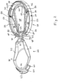
- the beverage can closure is an injection-molded part made of plastic, in particular polypropylene, with a base body 28 and a lid 32 integrally connected to the base body 28 via a film hinge 30.
- the base body includes a closed, circumferential clamp-shaped retaining ring 34, which, as in the Figures 2 and 5 can be clearly seen, is convexly curved on its radial inside, preferably essentially complementary to the outside of the annular groove 26.
- the retaining ring 34 has an overall elongated cross-sectional shape when viewed in axial section, which runs essentially parallel to the axial direction, i.e. to the central axis of the circular cylindrical section of the casing 16.
- a closed circumferential sealing web Integrally connected to the retaining ring 34 in the radial interior of the base body is a closed circumferential sealing web, which comprises longitudinal webs 36 which run laterally along the drinking opening 22 and the opening mechanism in the form of the closure ring 24.
- the longitudinal webs 36 also run somewhat obliquely to one another and define a central opening 38 between them, which is aligned with the unit consisting of the drinking opening 22 and locking ring 24 and is slightly larger than this unit , How Figure 6 shows.
- the longitudinal webs 36 essentially connect opposing retaining ring sections 40 and 42 to one another.
- Transverse webs 44, 46 connect the two longitudinal webs 36 to one another and together with them form a circumferential sealing web.
- two connecting ribs 48 are provided, via which the transverse web 44 at its radially outer side edge and the longitudinal web 36 merging into it in this area are connected in sections to the retaining ring 34 in one piece.
- the connecting ribs 48 extend in an arc upwards and finally downwards to the retaining ring 34 to form a receiving space 50 for the edge 20 and the edge region.
- a gap 52 is formed circumferentially between the connecting ribs 48, which is designed as an empty space without material.
- each longitudinal web 36 opposite the central opening 38 On the side of each longitudinal web 36 opposite the central opening 38, a free space 56 is provided in the base body 28 between the longitudinal web 36 and its immediately opposite retaining ring section 54, so that here too there is no material between the longitudinal web 36 and the retaining ring 34.
- the transverse web 46 is connected to the retaining ring 34 over the entire length of its radially outer side edge, including in the area of the transition to the longitudinal webs 36, via an intermediate section 53, so that this part of the closure is relatively stable.
- the lid 32 can be pivoted about the film hinge 30 and can close the central opening 38 and thus also the drinking opening 22.
- the lid 32 can be connected to the base body 28 via a detachable locking connection.
- a locking contour 58 with a wedge-shaped cross section is formed, which leads downwards to an undercut (see Figure 5 ).
- the cover 32 in turn has a corresponding locking geometry 60 with an outwardly projecting edge which can engage behind the locking geometry 58.
- the intermediate section 53 runs upwards and finally downwards again in an arc to the upper end of the retaining ring 34 and also has a receiving space 50 between itself and the retaining ring 34 in which the edge 20 and the edge region can be received.
- This intermediate section 53 which connects the crosspiece 44 to the retaining ring 34, will function in its middle section as a drinking rim 59 when the beverage can is opened and drunk from, because the can contents flow out via this drinking rim 59.
- the lid 32 has one, as in the Figures 1 and 5 can be clearly seen, radially protruding lip 62, which, when the beverage can closure is closed, covers the drinking edge 59 upwards.
- the lip 62 projects radially outward in sections to such an extent that, in the closed state, it projects laterally beyond the retaining ring 34 and can thus function as an operating surface for opening the closure.
- the longitudinal webs 36 preferably also the transverse webs 44, have holes 64 running through from the top to the bottom, only some of which are in Figure 2 are provided with reference numbers. Through these holes 64 it is possible to create a soft Sealing material is to be sprayed onto the webs 36, 44, 46 in a form-fitting manner in the 2-component spraying process and to be connected to them in a form-fitting manner.
- annular seal 68 or 70 runs both on the top and on the bottom of the sealing web (see Figure 4 ), whereby the seals 68, 70 merge into one another in one piece through the holes 64, because the holes 64 are filled with the sealing material.
- the difference between the Figures 2 and 4 in the area of the webs 36, 44, 46 shows where the circumferential seals 68, 70 are positioned.
- the seal 70 is provided essentially identically on the underside of the sealing web.
- the cover 32 has on its underside facing the base body 28, which is in the Figures 2 and 3 can be seen, a closed, circumferential narrow rib 71 with longitudinal ribs 72, which in the closed state come to rest on the seal 68 on the longitudinal webs 36, and transverse ribs 74, which in turn rest on the seal 68 in the area of the transverse webs 44, 46.
- the circumferential rib 71 rests on the sealing web, more precisely on the seal 68 of the sealing web, and compresses it.
- the embodiment shown is designed so that the lid 32 does not cover the free spaces 56 when the closure is closed, so that the longitudinal ribs 72 define the lateral end sections of the lid 32 in this area.
- FIG. 2 It can also be seen that the cover 32 is curved on its underside towards the top, ie through the ribs 72, 74 a receiving space 80 open from below (see Figure 5 ) which is large enough to accommodate an actuated closure ring 24 when the beverage can closure is closed.
- the lid with the circumferential rib 71 presses on and into the seal 68 in order to seal in a liquid-tight manner, and in addition, the seal 70 on the underside of the sealing web presses all around against the top of the end wall 18 and is deformed in the process, so that also A seal is created here to prevent liquid leakage.
- the sealing web is relative to the retaining ring 34 perpendicular to the plane E defined by the retaining ring and is therefore resilient in the vertical direction (with the can upright) on the retaining ring 34 appropriate. This ensures that the sealing web presses against the end wall 18 with pretension when the beverage can is closed and the end wall 18 is curved outwards, just as it is when the beverage can is open and the end wall 18 is essentially flat.
- the longitudinal webs 36 can be arched downwards towards the underside, as with a broken line in Figure 2 indicated.
- the arcuate curvature of the longitudinal webs 36 ensures that the longitudinal webs 36 can follow this movement distance.
- This arcuate curvature can of course also be realized by applying additional material or by correspondingly thickening the seal 70 in the middle section of the longitudinal webs 36.
- Beverage cans must be stackable. In order to achieve acceptance by the filler, the beverage can closure must not result in any additional stacking height.
- the beverage can closure in the closed state has on its upper side a recess 90 formed at least in circular segment sections, into which an annular bulge 92 provided on the base 14 of the can projects, whereby the can placed on the can 10 is held laterally as desired.
- the bulge 92 also forms the base or the base ring surface of each can.
- predefined contact points 94 are provided in the form of top sides of small projections, with three or four such contact points 94 preferably being present. For example, they prevent the bulge from resting on the lip 62.
- the retaining ring 34 is not connected to the rest, i.e. the inner section of the base body 28, over large circumferential sections, preferably over more than 45% of its circumference, and can be plastically stretched in the circumferential direction independently of the rest of the closure like a tension ring or tension band.
- the retaining ring 34 is significantly undersized compared to the annular groove 26, which creates tension on the longitudinal webs 36 when the beverage can closure is attached. This increases the pressing forces of the longitudinal webs 36 on the top of the end wall 18.
- the convex shape of the inside of the retaining ring 34 allows the closure to be conveniently pushed or attached from above onto the edge 20, such as Figure 5 shows. This means that the user can easily apply the forces needed to push it on or put it on.
- the beverage can closure can also be pulled upwards again from the beverage can 10 in a non-destructive manner and placed onto the next beverage can 10. So it is reusable.
- the seal 68 partially extends further upward in the second embodiment than in the first embodiment. In the second embodiment, the seal 68 lies partially against the connecting ribs 48 and the intermediate section 53.
- the seal 68 can even extend upwards so far that it partially even protrudes above the edge 20 of the beverage can 10 when the beverage can closure 12 is attached to the beverage can 10.
- the seal 68 points, as in Figure 8 can be seen, a step 95 which defines a side sealing surface 96 oriented towards the central opening 38.
- the side sealing surface 96 extends substantially perpendicular to plane E and extends completely around the central opening 38.
- the seal 68 has a base 98 between the side sealing surface 96 and the central opening 38.
- a groove (not shown) may also be formed in the bottom 98, wherein parts of the side sealing surface 96 may form one side of the wall of the groove.
- the contact surfaces or sealing surfaces on the lid 32 are formed on the outside, i.e. on the side of the rib 71 or the longitudinal ribs 72 and the transverse ribs 74 facing away from the central opening 38 in the closed state.
- the rib 71 is arranged between the central opening 38 and the side sealing surface 96 and lies sealingly against the side sealing surface 96.
- the side surfaces of the rib 71, i.e. the sealing surfaces, and the side sealing surface 96 come into contact, thereby creating a liquid-tight connection between the cover 32 and the seal 68.
- the seal 68 can also be compressed in this case.
- the sealing connection between the rib 71 and the side sealing surface 96 extends perpendicular to the plane E defined by the retaining ring and thus in the vertical direction (when the can is in an upright position), the connection remains liquid-tight even when the lid 32 or the rib 71 moves in the vertical direction relative to the seal 68.
- These slight relative movements can occur when beverage cans 10 containing carbonated beverages are resealed using the beverage can closure 12, whereby pressure builds up within the beverage can closure 12, which slightly deforms the lid 32.
- the rib 71 can also come into sealing contact with the base 98, thereby improving the sealing effect.
- the rib 71 can also engage in the groove.
- the side sealing surface 96 is not formed on a step 95, but the seal 68 has a different type of projection, edge, rim or the like on which the side sealing surface 96 is provided.
- the seal 70 also has an extension 99 which extends further downwards below parts of the webs 36, 44, 46.
- the extension 99 has a contour that is adapted to the recess 23 so that it protrudes into the recess 23. In addition, the extension 99 lies against the radially inner wall of the recess 23 and thus further seals the receiving space 80 of the beverage can closure 12.
- the seal 70 therefore not only rests on the front wall 18 in the flat area of the front wall 18, but also follows the contour of the front wall 18 in the area of the recess 23, in particular along the wall of the recess 23 on the drinking opening side. In this way, the sealing surface between the front wall 18 and the beverage can closure 12 is further enlarged and the sealing effect is improved.
- extension 99 can have a completely complementary shape to the recess 23 and thus completely fill the recess 23.
- the extension 99 is provided on the seal 70 in the areas of the transverse webs 44, 46 and in the areas of the connecting ribs 48 at the ends of the longitudinal webs 36. When installed, these areas are located above the recess 23. In addition, these areas are not connected, so that the extension 99 is designed in several parts.
- the side sealing surface 96 is provided on the seal 70 and/or the extension 99 extends from the seal 68.
- the seals 68, 70 in addition to their connection through the holes 64, also extend in one piece on the inside of the longitudinal and transverse webs 36, 44, ie the side facing the central opening 38 into each other. It is also conceivable that the seals 68, 70 merge into one another in one piece only on this inside.
- a locking contour 58 is also provided on the sections of the retaining ring 34 at which the ends of the longitudinal webs 36 facing away from the film hinge 30 are connected to the retaining ring 34. In this way, the locking contours 58 are not arranged in the area of the drinking rim 59.
- the locking contours 58 protrude perpendicular to the plane E from the retaining ring 34 and have an undercut or notch 100.
- the cover 32 in turn has corresponding locking geometries 60 with outwardly projecting edges 102 which can engage in the notches 100.
- edges 102 are designed to be resilient relative to the rest of the cover 32, for example by providing elongated openings 104 in the cover 32 on the inside of the edges 102.
- the individual features of the described embodiments can be combined with one another as desired.
- the type of locking can be selected independently of the shape of the seal.
- the extension 99 is also independent of the other features.
Landscapes
- Engineering & Computer Science (AREA)
- Mechanical Engineering (AREA)
- Closures For Containers (AREA)
Description
Die Erfindung betrifft einen wiederverschließbaren Getränkedosenverschluss zum Aufstecken auf eine Getränkedose sowie eine Doseneinheit aus Getränkedose und aufgesetztem Getränkedosenverschluss.The invention relates to a resealable beverage can closure for attaching to a beverage can and a can unit consisting of a beverage can and an attached beverage can closure.
Getränkedosen mit einem Einmalverschluss sind hinlänglich bekannt. Solche Dosen haben einen Mantel und einen Boden, die einstückig ineinander übergehen und durch Tiefziehen gebildet werden. Die Oberseite der Dose wird durch eine separat hergestellte Stirnwand, die mit dem Rest der Dose verschweißt wird, gebildet. In dieser Stirnwand, die üblicherweise wie der Rest der Dose aus Aluminium besteht, wird eine Trinköffnung durch Stanzen perforiert. Diese Trinköffnung kann dann einmalig geöffnet werden. Zum Öffnen gibt es verschiedene Öffnungsmechanismen, wobei der Wandabschnitt, um den die Perforation herumläuft, üblicherweise eingedrückt wird, sodass die Öffnung freigelegt wird. Im Falle von Getränkedosen hat sich ein an der Stirnwand befestigter Hebel, auch Verschlussring oder Pulltab genannt, durchgesetzt.Beverage cans with a disposable closure are well known. Such cans have a jacket and a base that merge into one another and are formed by deep drawing. The top of the can is formed by a separately manufactured end wall that is welded to the rest of the can. In this end wall, which is usually made of aluminum like the rest of the can, a drinking opening is perforated by punching. This drinking opening can then be opened once. There are various opening mechanisms for opening, but the section of wall around which the perforation runs is usually pushed in, exposing the opening. In the case of beverage cans, a lever attached to the front wall, also called a locking ring or pulltab, has become established.
Getränkedosen haben im Wesentlichen eine standardisierte Geometrie, wobei der Mantel stets über fast die gesamte axiale Höhe zylindrisch ausgeführt ist und am Boden der Dose eine geschlossen umlaufende, ringförmige Ausbauchung vorgesehen ist, über die eine ringförmige Standfläche gebildet ist. Diese ringförmige Ausbauchung ist für eine Stapelbarkeit wichtig, denn die Ausbauchung sitzt innenseitig eines nach oben vorstehenden oberen Randes der darunter stehenden Dose, der die darauf stehende Dose seitlich hält. Der Mantel hat ferner im Randbereich zur Stirnwand (Schweißbereich) eine umlaufende, seitliche radial nach außen offene Ringnut unterhalb seines zuvor erwähnten oberen Randes.Beverage cans essentially have a standardized geometry, with the casing always being cylindrical over almost the entire axial height and a closed, circumferential, ring-shaped bulge on the bottom of the can, over which a ring-shaped base is formed. This ring-shaped bulge is important for stackability, because the bulge is located on the inside of an upwardly protruding upper edge of the can underneath, which holds the can standing on top of it laterally. The casing also has a circumferential, lateral, radially outward-open ring groove below its previously mentioned upper edge in the edge area to the front wall (welding area).
Nachteilig ist, dass sich eine solche nur einmal freilegbare Öffnung in der Stirnwand nicht wieder verschließen lässt und somit der gesamte Inhalt der Dose auf einmal konsumiert werden muss oder verkommt. Außerdem können durch die freigelegte Öffnung unbemerkt Insekten in die Dose eindringen, wodurch die Gefahr besteht, dass die Insekten anschließend vom Konsumenten verschluckt werden.The disadvantage is that such an opening in the front wall, which can only be exposed once, cannot be closed again and thus the entire contents of the can must be consumed at once or it will go to waste. In addition, insects can enter the can unnoticed through the exposed opening, which There is a risk that the insects will subsequently be swallowed by the consumer.
Es gibt verschiedene Ansätze zur Realisierung einer verschließbaren Stirnwand. Jedoch dichten diese Verschlüsse die Öffnung nur unzureichend ab. Aufwendige wiederverschließbare Deckel oder Verschlussmechanismen, die an der Stirnwand von Haus aus befestigt sind, sind oft mehrteilig und damit teurer in der Produktion.There are various approaches to creating a lockable bulkhead. However, these closures do not seal the opening sufficiently. Complex resealable lids or locking mechanisms that are attached to the bulkhead are often made up of several parts and are therefore more expensive to produce.
Aus der gattungsbildenden
Darüber hinaus besteht seitens der Getränkehersteller oft kein Interesse an einer Wiederverschließbarkeit der Dose, weil der Verschlussmechanismus einerseits die Dose verteuert und damit den Gewinn reduziert und andererseits der Gesamtkonsum zurückgeht.In addition, beverage manufacturers are often not interested in resealability of the can because, on the one hand, the closing mechanism makes the can more expensive and thus reduces profits and, on the other hand, overall consumption decreases.
Aufgabe der Erfindung ist es deshalb, einen wiederverschließbaren Getränkedosenverschluss sowie eine Doseneinheit aus Getränkedose und Getränkedosenverschluss zu schaffen, durch die die dosenseitig nur einmal zu öffnende Trinköffnung wiederverschließbar ist. Der Getränkedosenverschluss nach der Erfindung soll einfach herstellbar sein und vor allem zuverlässig gegenüber der Stirnwand der Dose abdichten.The object of the invention is therefore to create a resealable beverage can closure and a can unit consisting of a beverage can and a beverage can closure, through which the drinking opening on the can side, which only needs to be opened once, can be resealed. The beverage can closure according to the invention should be easy to manufacture and, above all, should seal reliably against the front wall of the can.
Die obige Aufgabe wird durch einen wiederverschließbaren Getränkedosenverschluss gemäß Anspruch 1 gelöst, der auf eine Getränkedose aufsteckbar ist und einen dosenseitig befestigbaren Grundkörper und einen am Grundkörper angebrachten, zum Grundkörper beweglichen Deckel zum reversiblen Wiederverschließen der Getränkedose aufweist. Der Grundkörper besitzt einen umlaufenden Haltering zum Einrasten, das heißt Einschnappen, in die Ringnut im Randbereich des Mantels der Dose sowie mit dem Haltering einstückig verbundene, an eine zentrale Öffnung im Grundkörper angrenzende Längsstege zur Anlage an die Seitenwand seitlich der Trinköffnung. Die zentrale Öffnung ist um die Trinköffnung herum ausgeführt und legt diese bei geöffnetem Getränkedosenverschluss frei, entweder zum erstmaligen Öffnen der Trinköffnung in der Stirnwand oder nach dem Öffnen zum Leeren der Getränkedose. Die Längsstege verlaufen zum Haltering quer und verbinden im Wesentlichen gegenüberliegende Halteabschnitte miteinander, wobei zwischen den Längsstegen und den benachbarten Abschnitten des Halterings jeweils wenigstens ein Freiraum vorhanden ist. Dieser Freiraum ist sozusagen ein Loch im Grundkörper. Zwischen den Längsstegen liegt die zentrale Öffnung. Auf der anderen Seite der jeweiligen Längsstege ist dann der zuvor erwähnte Freiraum vorhanden, der sicherstellt, dass in diesem Bereich der Haltering freiliegt und nicht mit einem oberseitigen Wandabschnitt des Grundkörpers gekoppelt ist. Da damit der Haltering im Bereich der Freiräume freiliegende schellenartige Abschnitte besitzt, ist der Haltering in Umfangsrichtung deutlich flexibler als bei Ausführungsformen, bei denen der Haltering umlaufend einstückig in eine obere Wand des Grundkörpers übergeht, die die Stirnwand komplett bedeckt. Aufgrund dieser höheren Flexibilität des Halterings lässt sich dieser einfacher auf die Getränkedose aufstecken und vor allem mit einem größeren Untermaß zur Dosenaußengeometrie versehen. Darüber hinaus wird durch dieses Untermaß bei der erfindungsgemäßen Ausführungsform weniger Einfluss auf die wichtigen Dichtflächen genommen, die im vorliegenden Fall durch die Längsstege gebildet sind. Der Deckel weist auf seiner dem Grundkörper zugewandten Unterseite benachbarte Längsrippen auf, wobei jede Längsrippe einem Längssteg zugeordnet ist und im geschlossenen Zustand des Getränkedosenverschlusses dichtend mit dem Längssteg zusammenwirkt, vorzugsweise dichtend an ihm anliegt. Über diese Längsrippen wird eine relativ schmale Andrückfläche oder Andrücklippe realisiert, die eine bessere Dichtwirkung als eine breite Rippe erzeugt. Da die Dichtwirkung immer durch plastische Verformung eines oder beider übereinanderliegender und aufeinanderliegender Abschnitte oder Teile geschaffen wird, kann bei gleicher Anpresskraft und einer geringeren, durch eine schmalere Längsrippe ausgebildeten Kontaktfläche eine höhere elastische Verformung der aufeinandergepressten Abschnitte oder Teile erzielt werden, was der Dichtung zuträglich ist.The above object is achieved by a resealable beverage can closure according to claim 1, which can be attached to a beverage can and has a base body that can be fastened to the can side and a lid attached to the base body and movable relative to the base body for reversibly resealing the beverage can. The base body has a circumferential retaining ring for locking, i.e. snapping, into the annular groove in the edge area of the jacket of the can as well as longitudinal webs connected in one piece with the retaining ring and adjacent to a central opening in the base body. to rest against the side wall to the side of the drinking opening. The central opening is designed around the drinking opening and exposes it when the beverage can closure is opened, either for the first time opening the drinking opening in the front wall or after opening to empty the beverage can. The longitudinal webs run transversely to the retaining ring and essentially connect opposite holding sections to one another, with at least one free space between the longitudinal webs and the adjacent sections of the retaining ring. This free space is, so to speak, a hole in the base body. The central opening is located between the longitudinal webs. On the other side of the respective longitudinal webs there is then the previously mentioned free space, which ensures that the retaining ring is exposed in this area and is not coupled to an upper wall section of the base body. Since the retaining ring thus has clamp-like sections exposed in the area of the free spaces, the retaining ring is significantly more flexible in the circumferential direction than in embodiments in which the retaining ring merges in one piece all the way around into an upper wall of the base body that completely covers the front wall. Due to this greater flexibility of the retaining ring, it can be more easily placed on the beverage can and, above all, given a larger undersize to the can's outer geometry. In addition, this undersize in the embodiment according to the invention has less influence on the important sealing surfaces, which in the present case are formed by the longitudinal webs. The lid has adjacent longitudinal ribs on its underside facing the base body, whereby each longitudinal rib is assigned to a longitudinal web and, when the beverage can closure is closed, cooperates with the longitudinal web to form a seal, preferably resting against it. A relatively narrow pressing surface or pressing lip is created via these longitudinal ribs, which creates a better sealing effect than a wide rib. Since the sealing effect is always created by plastic deformation of one or both of the sections or parts lying on top of one another and on top of one another, a higher elastic deformation of the sections or parts pressed against one another can be achieved with the same contact force and a smaller contact surface formed by a narrower longitudinal rib, which is beneficial for the seal.
Mit dem Aufstecken oder Aufstülpen eines Verschlusses verändert sich natürlich immer die gesamte Form des Verschlusses durch die plastischen Dehnungen am Rand. Insbesondere wird dann, wenn eine obere Wand eines aufgestülpten Grundkörpers umlaufend komplett in einen Haltering übergeht wie im Stand der Technik, die Wand zwangsläufig wie ein Trampolin gespannt und damit von der Stirnwand weggedrückt. Dieser Effekt wird durch die Erfindung ausgeschlossen. Indem darüber hinaus die Längsstege seitlich der Öffnung verlaufen, können diese sehr einfach mit hohen Zugspannungen beaufschlagt werden und wie Spannriemen wirken. Da sich eine Getränkedose, wenn sie geschlossen ist, durch eine nach oben auswölbende Stirnwand auszeichnet, können die gespannten Längsstege gegen die nach oben gewölbte Stirnwand drücken und dichtend abschließen.When a fastener is put on or put on, the entire shape of the fastener naturally changes due to the plastic expansion at the edge. In particular, when an upper wall of a base body that is pushed on completely merges all around into a retaining ring, as in the prior art, the wall is inevitably stretched like a trampoline and is thus pushed away from the end wall. This effect is excluded by the invention. Because the longitudinal webs run to the side of the opening, they can easily be subjected to high tensile stresses and act like tension belts. Since a beverage can is characterized by an upwardly bulging end wall when it is closed, the tensioned longitudinal webs can press against the upwardly bulging end wall and form a seal.
Ist die Dose einmal geöffnet und wird sie dann wieder geschlossen und beispielsweise geschüttelt, können die Längsstege wieder elastisch weiter gedehnt werden, um sich der erneut ausbauchenden Stirnwand anzupassen und gegen sie zu drücken.Once the can has been opened and it is then closed again and, for example, shaken, the longitudinal webs can be further stretched elastically in order to adapt to the end wall, which bulges out again, and to press against it.
Gemäß einer Ausführungsform der vorliegenden Erfindung ist vorgesehen, dass zumindest über 35 %, insbesondere über wenigstens 45 %, der Umfangslänge des Halterings Freiräume angrenzen, das heißt, dass in diesen Abschnitten der Haltering tatsächlich nur als Schellenabschnitt ausgeführt ist und nicht nach oben über den oberen Rand in einen stirnseitigen Abschnitt des Grundkörpers übergeht.According to one embodiment of the present invention, it is provided that at least over 35%, in particular over at least 45%, of the circumferential length of the retaining ring are adjacent to free spaces, which means that in these sections the retaining ring is actually only designed as a clamp section and not upwards over the upper one Edge merges into a front section of the base body.
Im Bereich der Enden der Längsstege sind beispielsweise die Längsstege verbindende Querstege vorgesehen. Längs- und Querstege zusammen bilden einen geschlossen umlaufenden, die Trinköffnung umgebenden und an der Stirnwand anliegenden Dichtsteg, der wiederum die zentrale Öffnung umgibt oder die zentrale Öffnung auch definiert. Die Dichtwirkung zwischen dem Getränkedosenverschluss und der Getränkedose wird also ausschließlich durch Kontakt an der Stirnwand der Dose realisiert.In the area of the ends of the longitudinal webs, for example, transverse webs connecting the longitudinal webs are provided. The longitudinal and transverse webs together form a closed sealing web that surrounds the drinking opening and rests against the end wall, which in turn surrounds the central opening or also defines the central opening. The sealing effect between the beverage can closure and the beverage can is therefore achieved exclusively through contact on the end wall of the can.
Zumindest ein Quersteg kann längs seines gesamten Seitenrandes einstückig über einen Zwischenabschnitt in den Haltering übergehen, sodass in diesem Bereich ein Abschnitt (Zwischenabschnitt) des Grundkörpers vom Haltering über den oberen Rand der Dose zu dem Teil des Verschlusses verläuft, der über der Stirnwand liegt. Dieser Teil ist in diesem Fall der Quersteg. Im Bereich des Zwischenabschnitts wird der Getränkedosenverschluss folglich versteift, was es erlaubt, hier andere Funktionen, die eine steife Geometrie erfordern, vorzusehen.At least one crossbar can merge into the retaining ring in one piece along its entire side edge via an intermediate section, so that in this area a section (intermediate section) of the base body runs from the retaining ring over the upper edge of the can to the part of the closure that is above the The front wall is located. In this case, this part is the crossbar. In the area of the intermediate section, the beverage can closure is consequently stiffened, which allows other functions that require a rigid geometry to be provided here.
Es ist aber auch möglich, dass zumindest ein Quersteg längs seines Seitenrandes durch Verbindungsrippen nur abschnittsweise einstückig in den Haltering übergeht und zwischen den Verbindungsrippen ein Spalt vorhanden ist. Durch diese Variante wird die Umfangslänge, in der der Haltering tatsächlich nur als Schellenabschnitt ausgeführt ist, vergrößert.However, it is also possible for at least one crossbar along its side edge to merge into the retaining ring in one piece only in sections through connecting ribs and for a gap to be present between the connecting ribs. This variant increases the circumferential length in which the retaining ring is actually only designed as a clamp section.
Um die Dichtwirkung sowohl bei bereits geöffneter Dose als auch bei noch verschlossener Dose und bei einer bereits geöffneten und wieder unter Innendruck gesetzten Dose (durch Schütteln der Dose) zu optimieren, kann der Dichtsteg gegenüber dem Haltering senkrecht zu der durch den Haltering definierten Ebene so federnd zum Haltering ausgebildet sein, dass der Dichtsteg bei geschlossener Getränkedose und nach außen gewölbter Stirnwand sowie bei geöffneter Getränkedose und im Wesentlichen ebener Stirnwand mit Vorspannung gegen die Stirnwand drückt. Der Haltering liegt mit seinem unteren Rand in einer Ebene oder definiert in der montierten Stellung durch die Ringnut eine Ebene. Nachdem der Haltering nicht federnd senkrecht zur Stirnwand beweglich ist, wenn er auf der Getränkedose aufgeschnappt ist, ist der Dichtsteg ihm gegenüber beweglich ausgeführt.In order to optimise the sealing effect both when the can is already opened and when it is still closed, and when the can is already opened and the internal pressure is re-pressurised (by shaking the can), the sealing web can be designed to be resilient relative to the retaining ring perpendicular to the plane defined by the retaining ring, so that the sealing web presses against the end wall with pre-tension when the drinks can is closed and the end wall is curved outwards, and when the drinks can is open and the end wall is essentially flat. The lower edge of the retaining ring lies in one plane or, in the assembled position, defines a plane through the ring groove. Since the retaining ring cannot be moved resiliently perpendicular to the end wall when it is snapped onto the drinks can, the sealing web is designed to be movable relative to it.
Im nicht an der Getränkedose montierten Zustand des Getränkedosenverschlusses können die Längsstege und/oder die Querstege zur Unterseite bogenförmig gewölbt verlaufen. Das bedeutet, die Längsstege bauchen im Ausgangszustand bereits in Richtung zur Stirnwand aus, um eine Federwirkung, ähnlich einer vorgespannten Blattfeder, zu realisieren und den Druck auf die Stirnwand dort zu erhöhen, wo sie auch am meisten beim Öffnen der Dose zurückfedert.When the beverage can closure is not mounted on the beverage can, the longitudinal webs and/or the transverse webs can be curved towards the underside. This means that in the initial state the longitudinal webs bulge towards the front wall in order to create a spring effect, similar to a pre-tensioned leaf spring, and to increase the pressure on the front wall where it springs back most when the can is opened.
Die bevorzugte Ausführungsform der Erfindung sieht vor, dass der Dichtsteg vollständig unterhalb des oberen Randes der Dose, auf die der Getränkedosenverschluss aufgeschnappt ist, liegt. Er liegt damit in der Vertiefung, die zwischen dem nach oben vorstehenden oberen Rand der Dose und seiner Stirnwand gebildet ist. Dies stellt sicher, dass beim Stapeln von Dosen, die mit dem erfindungsgemäßen Getränkedosenverschluss ausgestattet sind, keine wesentliche Erhöhung der Stapelhöhe einhergeht.The preferred embodiment of the invention provides that the sealing web lies completely below the upper edge of the can onto which the beverage can closure is snapped. It lies in the recess that is formed between the upwardly projecting upper edge of the can and its end wall. This ensures that when stacking cans with equipped with the beverage can closure according to the invention, there is no significant increase in the stack height.
Der Deckel kann über ein Schwenklager, insbesondere ein Filmscharnier, mit dem Grundkörper verbunden sein, sodass Deckel und Grundkörper eine einstückige Einheit bilden.The lid can be connected to the base body via a pivot bearing, in particular a film hinge, so that the lid and base body form a one-piece unit.
Die bevorzugte Ausführungsform der Erfindung sieht natürlich vor, dass der Getränkedosenverschluss nach der Erfindung komplett aus Kunststoff ausgeführt ist.The preferred embodiment of the invention naturally provides that the beverage can closure according to the invention is made entirely of plastic.
Das Schwenklager kann im Bereich des Spalts vorgesehen sein, der zwischen den Verbindungsrippen des Querstegs mit dem Haltering definiert ist. Damit wird darüber hinaus auch noch mehr Platz für den Teil des Deckels geschaffen, der nahe dem Filmscharnier liegt.The pivot bearing can be provided in the area of the gap defined between the connecting ribs of the crosspiece and the retaining ring. This also creates more space for the part of the cover that is close to the film hinge.
Der Deckel kann ferner über eine Rastverbindung lösbar am Grundkörper in der geschlossenen Stellung des Getränkedosenverschlusses gehalten sein, das heißt, er ist einfach zu öffnen und zu schließen.The lid can also be detachably held on the base body in the closed position of the beverage can closure via a snap-in connection, i.e. it is easy to open and close.
Eine am Grundkörper vorgesehene Verriegelungsgeometrie des Rastkörpers, die mit einer entsprechenden Verriegelungsgeometrie am Deckel zusammenwirkt, kann am Zwischenabschnitt, der in einen Quersteg und in den Haltering übergeht, ausgeformt sein. Insbesondere ist dies natürlich an demjenigen Quersteg vorgesehen, der längs seines gesamten Seitenrandes einstückig über den Zwischenabschnitt mit dem Haltering verbunden ist und damit einen sehr steifen Abschnitt des Getränkedosenverschlusses bildet. Auch kann die Verriegelungsgeometrie des Rastkörpers am Grundkörper im Bereich eines Längsstegs ausgebildet sein, insbesondere an einer der beiden Verbindungsrippen, mit denen jeder Längssteg am Haltering verbunden ist. Vorzugsweise im Bereich der vom Filmscharnier abgewandten Seiten der Längsstege.A locking geometry of the latching body provided on the base body, which interacts with a corresponding locking geometry on the lid, can be formed on the intermediate section, which merges into a crosspiece and the retaining ring. In particular, this is of course provided on the crosspiece that is connected to the retaining ring in one piece along its entire side edge via the intermediate section and thus forms a very rigid section of the beverage can closure. The locking geometry of the latching body can also be formed on the base body in the area of a longitudinal web, in particular on one of the two connecting ribs with which each longitudinal web is connected to the retaining ring. Preferably in the area of the sides of the longitudinal webs facing away from the film hinge.
Vorzugsweise hat der Deckel auf seiner Unterseite eine geschlossen umlaufende, vorzugsweise durch eine umlaufende Rippe definierte Anpressfläche, die im geschlossenen Zustand des Verschlusses dichtend mit dem Dichtsteg zusammenwirkt, vorzugsweise geschlossen umlaufend am Dichtsteg anliegt.Preferably, the lid has on its underside a closed circumferential pressure surface, preferably defined by a circumferential rib, which cooperates sealingly with the sealing web when the closure is closed, preferably rests in a closed circumferential manner on the sealing web.
Zur verbesserten Abdichtung kann der Grundkörper an seiner der Stirnwand zugewandten Unterseite und/oder an einer dem Deckel zugewandten Oberseite eine geschlossen um die zentrale Öffnung herum verlaufende elastische Dichtung aufweisen. Die Dichtung ist aus einem weicheren und elastischeren Material als der Rest des Grundkörpers.For improved sealing, the base body can have an elastic seal that runs closed around the central opening on its underside facing the front wall and/or on an upper side facing the lid. The seal is made of a softer and more elastic material than the rest of the base body.
Eine einfache Fertigung des erfindungsgemäßen Getränkedosenverschlusses ergibt sich dadurch, dass der Getränkedosenverschluss ein 2-K-Spritzgussteil ist, wobei eine Komponente den Grundkörper und den Deckel und die andere Komponente die Dichtung beziehungsweise die Dichtungen bildet.A simple manufacture of the beverage can closure according to the invention results from the fact that the beverage can closure is a 2-component injection-molded part, with one component forming the base body and the lid and the other component forming the seal or seals.
Zur besseren Halterung des Dichtwerkstoffs auf dem Werkstoff des Grundkörpers können zumindest die Längsstege, vorzugsweise auch noch zusätzlich die Querstege, von der Ober- bis zur Unterseite durchgehende Löcher besitzen. Durch diese Löcher erstreckt sich das Dichtmaterial, welches die Dichtung an der Oberseite und welches die Dichtung an der Unterseite bildet. Damit gehen diese Dichtungen einstückig ineinander über, und es ist ein Formschluss der Dichtungen gegenüber dem Rest des Getränkedosenverschlusses erreicht.To better hold the sealing material on the material of the base body, at least the longitudinal webs, and preferably also the transverse webs, can have holes through them from the top to the bottom. The sealing material, which forms the seal on the top and the seal on the bottom, extends through these holes. These seals thus merge into one another in one piece, and a positive fit of the seals with respect to the rest of the beverage can closure is achieved.
Eine besonders wirksame Abdichtung wird durch eine um die zentrale Öffnung herum verlaufende Seitendichtfläche erzielt, die Teil der Dichtung und somit des Dichtstegs ist und die sich im Wesentlichen senkrecht zur zentralen Öffnung erstreckt. Diese Seitendichtfläche kann mit den Anpressflächen, insbesondere den Seiten der Rippe des Deckels, zusammenwirken, um den Getränkedosenverschluss dicht zu verschließen.A particularly effective seal is achieved by a side sealing surface running around the central opening, which is part of the seal and thus of the sealing web and which extends essentially perpendicular to the central opening. This side sealing surface can interact with the contact surfaces, in particular the sides of the rib of the lid, in order to tightly close the beverage can closure.
Auch kann die Dichtung einen Boden aufweisen, der zwischen der Seitendichtfläche und der zentralen Öffnung vorgesehen ist. Hierdurch wird eine weitere Dichtfläche geschaffen, an der die Anpressfläche anliegen kann, wodurch die Dichtwirkung der Dichtung weiter verbessert. Der Boden kann zudem zum verbesserten Sitz des Deckels an der Dichtung mit einer Nut versehen sein, wobei Teile der Seitenfläche die Nut an einer Seite begrenzen können.The seal can also have a base that is provided between the side sealing surface and the central opening. This creates a further sealing surface against which the contact surface can rest, thereby further improving the sealing effect of the seal. The base can also be provided with a groove to improve the fit of the cover on the seal, whereby parts of the side surface can limit the groove on one side.
Zur Abdichtung des Getränkedosenverschlusses kann die Anpressfläche im geschlossenen Zustand des Getränkedosenverschlusses dichtend an der Seitendichtwand teilweise anliegen, insbesondere auf der der zentralen Öffnung zugewandten Seite der Seitendichtwand teilweise anliegen.To seal the beverage can closure, the contact surface can be sealed against the Partially abut the side sealing wall, in particular partially abut the side of the side sealing wall facing the central opening.
Eine Verbesserung der Dichtwirkung zwischen der Stirnwand der Getränkedose und dem Getränkedosenverschluss kann dadurch erreicht werden, dass die Dichtung zumindest einen Fortsatz aufweist, der sich zumindest abschnittsweise unterhalb wenigstens einer der Längs- und/oder der Querstege von diesem Längs- und/oder Quersteg weg weiter abwärts erstreckt, wobei der Fortsatz derart ausgebildet ist, dass er in die Vertiefung der Stirnwand dichtend eingreifen kann. Dabei ist der Fortsatz beispielsweise in den Abschnitten der Dichtung ausgebildet, die im aufgesetzten Zustand des Getränkedosenverschlusses oberhalb der Vertiefung angeordnet sind. Die Kontur des Fortsatzes ist vorzugsweise komplementär zur Kontur der Vertiefung, insbesondere komplementär zur trinköffnungsseitigen Wandung der Vertiefung, sodass sich die Dichtung auch im Bereich der Vertiefung an die Stirnwand anpassen und diese abdichten kann.An improvement in the sealing effect between the front wall of the beverage can and the beverage can closure can be achieved in that the seal has at least one extension which extends further downwards, at least in sections, below at least one of the longitudinal and/or transverse webs, away from this longitudinal and/or transverse web, wherein the extension is designed such that it can engage in the recess of the front wall in a sealing manner. The extension is designed, for example, in the sections of the seal which are arranged above the recess when the beverage can closure is in place. The contour of the extension is preferably complementary to the contour of the recess, in particular complementary to the wall of the recess on the drinking opening side, so that the seal can also adapt to the front wall in the region of the recess and seal it.
Um eine sichere Stapelbarkeit von Getränkedosen, die mit dem erfindungsgemäßen Verschluss versehen sind, zu erreichen, kann der Getränkedosenverschluss in seinem geschlossenen Zustand auf seiner Oberseite eine zumindest in Kreissegmentabschnitten ausgebildete Vertiefung besitzen. Diese Vertiefung dient dazu, die zuvor erwähnte ringförmige Ausbauchung der Dose zur Bildung der Standfläche aufzunehmen. Damit wird die auf den erfindungsgemäßen Verschluss aufgesetzte Dose seitlich gehalten.In order to ensure that beverage cans provided with the closure according to the invention can be safely stacked, the beverage can closure can have a recess formed at least in circular segment sections on its top side when closed. This recess serves to accommodate the previously mentioned ring-shaped bulge of the can to form the base. This holds the can placed on the closure according to the invention laterally.
Im Bereich der Vertiefung können vorbestimmte, vorstehende Kontaktstellen zur Auflage der Ausbauchung ausgebildet sein, sodass die darauf gestapelte Dose nur an wenigen, vordefinierten Punkten auf dem erfindungsgemäßen Verschluss steht. Dies dient auch zu Hygienezwecken, denn der Bereich, der möglicherweise vom Benutzer mit dem Mund kontaktiert wird, sollte zuvor nicht durch eine aufgesetzte Dose kontaktiert worden sein.In the area of the recess, predetermined, projecting contact points can be formed to support the bulge, so that the can stacked thereon only rests on the closure according to the invention at a few predefined points. This is also for hygiene purposes, as the area that may be contacted by the user's mouth should not have been previously contacted by an attached can.
Die zentrale Öffnung im Grundkörper sollte insbesondere so groß sein, dass die Trinköffnung und ein an der Stirnwand der Dose vorgesehener Verschlussring zum Öffnen der Trinköffnung vollständig in der zentralen Öffnung liegen. Die zentrale Öffnung sorgt damit dafür, dass sowohl die Trinköffnung zugänglich ist als auch der Öffnungsmechanismus an der Dose.The central opening in the base body should be large enough so that the drinking opening and a locking ring provided on the front wall of the can for opening the drinking opening lie completely in the central opening. The central opening therefore ensures that both the drinking opening and the opening mechanism on the can are accessible.
Insbesondere hat die zentrale Öffnung eine längliche Gestalt, wobei die Öffnung an einem Längsende breiter als am gegenüberliegenden Längsende ist. Die Längsstege verlaufen somit insbesondere im Wesentlichen schräg aufeinander zu beziehungsweise voneinander weg.In particular, the central opening has an elongated shape, with the opening being wider at one longitudinal end than at the opposite longitudinal end. The longitudinal webs therefore run essentially obliquely towards or away from each other.
Der Deckel kann an seiner Unterseite zur Oberseite hin gewölbt sein, um im geschlossenen Zustand des Getränkedosenverschlusses einen betätigten Verschlussring aufzunehmen. Diese Verschlussringe werden ja beim Öffnen einmal hochgezogen und umgebogen. Die Verschlussringe bleiben üblicherweise aus Umweltgesichtspunkten an der Stirnwand befestigt und stehen damit weiter nach oben vor als im unbetätigten Zustand. Der so geformte Deckel schließt auch sicher bei einem noch an der Stirnwand befestigten, aber bereits betätigten Verschlussring.The lid can be curved from the bottom to the top to accommodate an activated locking ring when the beverage can closure is closed. These locking rings are pulled up and bent over when opened. For environmental reasons, the locking rings usually remain attached to the front wall and thus protrude further upwards than when not activated. The lid shaped in this way also closes securely when the locking ring is still attached to the front wall but has already been activated.
Wie bereits erläutert geht der Haltering an seinem oberen Ende in einen Abschnitt über, der sich über den den Mantel und die Stirnwand verbindenden oberen Rand der Dose in Richtung zur Stirnwand erstreckt und damit den oberen Rand der Dose abschnittsweise abdeckt. Dieser Abschnitt bildet einen Trinkrand. Der Trinkrand sollte an demjenigen Abschnitt des Halterings liegen, der der Trinköffnung am nächsten liegt.As already explained, the upper end of the retaining ring merges into a section that extends over the upper edge of the can that connects the jacket and the front wall in the direction of the front wall, thus covering the upper edge of the can in sections. This section forms a drinking rim. The drinking rim should be located on the section of the retaining ring that is closest to the drinking opening.
Um den Trinkrand hygienisch abzudecken, kann eine vorstehende Lippe am Deckel vorgesehen sein. Diese Lippe überdeckt im geschlossenen Zustand des Getränkedosenverschlusses den Trinkrand und legt ihn bei geöffnetem Getränkedosenverschluss frei.In order to hygienically cover the drinking rim, a protruding lip can be provided on the lid. This lip covers the drinking rim when the beverage can closure is closed and exposes it when the beverage can closure is open.
Die Erfindung betrifft darüber hinaus eine Doseneinheit aus einer Getränkedose der vorgenannten Art, die nämlich einen Mantel und eine Stirnwand besitzt, die eine durch einen Einmalverschluss verschlossene Trinköffnung aufweist, wobei der Mantel im Bereich zur Stirnwand eine umlaufende seitliche Ringnut hat. Darüber hinaus umfasst die erfindungsgemäße Doseneinheit einen erfindungsgemäßen Getränkedosenverschluss.The invention further relates to a can unit made from a beverage can of the aforementioned type, which has a casing and a front wall which has a drinking opening closed by a disposable closure, wherein the casing has a circumferential lateral annular groove in the area of the front wall. Furthermore, the can unit according to the invention comprises a beverage can closure according to the invention.
Dieser Getränkedosenverschluss kann zerstörungsfrei von der Getränkedose lösbar sein und damit an einer noch vollen Dose wieder benutzt werden.This beverage can closure can be removed from the beverage can without causing any damage and can therefore be reused on a can that is still full.
Die Begriffe "oben" und "unten" beziehen sich auf den Zustand, in dem der Getränkedosenverschluss auf eine Getränkedose aufgesetzt ist und die Getränkedose waagerecht, mit der Trinköffnung nach oben, auf einer Unterlage steht.The terms "top" and "bottom" refer to the state in which the beverage can closure is placed on a beverage can and the Beverage can stands horizontally on a surface with the drinking opening facing upwards.
Weitere Merkmale und Vorteile der Erfindung ergeben sich aus der nachfolgenden Beschreibung und aus den nachfolgenden Zeichnungen, auf die Bezug genommen wird.Further features and advantages of the invention emerge from the following description and from the following drawings, to which reference is made.
In den Zeichnungen zeigen:
- - Figur 1
- eine perspektivische Draufsicht auf eine erfindungsgemäße Doseneinheit mit einer Getränkedose und einem darauf aufgesteckten erfindungsgemäßen Getränkedosenverschluss,
- - Figur 2
- eine perspektivische Ansicht des erfindungsgemäßen Getränkedosenverschlusses im geöffneten Zustand,
- - Figur 3
- eine Draufsicht auf den geöffneten Getränkedosenverschluss nach
Figur 2 , - - Figur 4
- eine Schnittansicht längs der Linie IV-IV in
Figur 1 durch einen Abschnitt eines Längsstegs, - - Figur 5
- eine Längsschnittansicht durch eine erfindungsgemäße Doseneinheit mit darauf gestapelter Getränkedose,
- - Figur 6
- eine perspektivische Ansicht der erfindungsgemäßen Doseneinheit nach
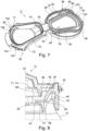
Figur 1 bei geöffnetem Deckel, - - Figur 7
- eine perspektivische Ansicht einer zweiten Ausführungsform des erfindungsgemäßen Getränkedosenverschlusses im geöffneten Zustand, und
- - Figur 8
- eine teilweise Schnittansicht einer erfindungsgemäßen Doseneinheit mit dem Getränkedosenverschlusses der
Figur 7 in geschlossenem Zustand.
- - Figure 1
- a perspective top view of a can unit according to the invention with a beverage can and a beverage can closure according to the invention attached thereto,
- - Figure 2
- a perspective view of the beverage can closure according to the invention in the opened state,
- - Figure 3
- a top view of the opened beverage can closure after
Figure 2 , - - Figure 4
- a sectional view along the line IV-IV in
Figure 1 through a section of a longitudinal web, - - Figure 5
- a longitudinal sectional view through a can unit according to the invention with a beverage can stacked on top,
- - Figure 6
- a perspective view of the can unit according to the invention
Figure 1 with the lid open, - - Figure 7
- a perspective view of a second embodiment of the beverage can closure according to the invention in the opened state, and
- - Figure 8
- a partial sectional view of a can unit according to the invention with the beverage can closure of the
Figure 7 in closed position.
In
Die Getränkedose 10 besteht im Wesentlichen aus einem Boden 14, der in
In der Stirnwand 18 ist eine Trinköffnung 22 durch eine Prägung vordefiniert, welche durch einen Einmalverschluss mit einem Öffnungsmechanismus, beispielsweise einem an der Stirnwand 18 befestigten Verschlussring, verschlossen bzw. einmalig geöffnet werden kann. Der Verschlussring wird auch als Pulltab bezeichnet.In the
Die Stirnwand 18 weist zudem eine Vertiefung 23 auf, die zwischen dem Rand 20 und der Trinköffnung 22 vorgesehen ist. Die Vertiefung 23 kann in Draufsicht die Form des Randes 20 haben, jedoch mit einem geringeren Radius als der Rand 20. Auch umschließt die Vertiefung 23 die Trinköffnung 22 vollständig. Die Vertiefung 23 kann als Nut ausgebildet sein.The
Wie in
Auf die Getränkedose 10 ist ein Getränkedosenverschluss 12 aufgesteckt oder, mit anderen Worten, aufgeklipst, der die Ringnut 26 als Halterung benutzt.A beverage can
Der Getränkedosenverschluss ist ein Spritzgussteil aus Kunststoff, insbesondere Polypropylen, mit einem Grundkörper 28 und einem über ein Filmscharnier 30 mit dem Grundkörper 28 einstückig verbundenen Deckel 32.The beverage can closure is an injection-molded part made of plastic, in particular polypropylene, with a
Der Grundkörper umfasst einen geschlossen umlaufenden schellenförmigen Haltering 34, der, wie in den
Der Haltering 34 hat aber insgesamt eine im Axialschnitt gesehen längliche Querschnittsgestalt, die im Wesentlichen parallel zur Axialrichtung, d. h. zur Mittelachse des kreiszylindrischen Abschnitts des Mantels 16 verläuft.However, the retaining
Einstückig mit dem Haltering 34 verbunden ist im radialen Inneren des Grundkörpers ein geschlossen umlaufender Dichtsteg, welcher Längsstege 36 umfasst, die seitlich entlang der Trinköffnung 22 und des Öffnungsmechanismus in Form des Verschlussrings 24 verlaufen. Dadurch, dass die Trinköffnung 22 zu ihrem vom Verschlussring 24 entfernten Ende etwas breiter wird, ergibt sich insgesamt für die Einheit aus Trinköffnung 22 und Verschlussring 24 eine leicht ovale Umhüllende. Um den Zugang zur Trinköffnung 22 komplett zu ermöglichen ebenso wie zum Verschlussring 24, verlaufen die Längsstege 36 ebenfalls etwas schräg zueinander und definieren zwischen sich eine zentrale Öffnung 38, die mit der Einheit aus Trinköffnung 22 und Verschlussring 24 fluchtet und etwas größer als diese Einheit ist, wie
Die Längsstege 36 verbinden im Wesentlichen gegenüberliegende Halteringabschnitte 40 bzw. 42 miteinander. Querstege 44, 46 verbinden die beiden Längsstege 36 miteinander und bilden gemeinsam mit diesen einen umlaufenden Dichtsteg.The
Im Bereich des Querstegs 44 sind zwei Verbindungsrippen 48 vorgesehen, über die der Quersteg 44 an seinem radial äußeren Seitenrand und der in diesem Bereich in ihn übergehende Längssteg 36 mit dem Haltering 34 abschnittsweise einstückig verbunden ist.In the area of the
Die Verbindungsrippen 48 erstrecken sich bogenförmig aufwärts und schließlich abwärts zum Haltering 34, um einen Aufnahmeraum 50 für den Rand 20 und den Randbereich zu bilden.The connecting
Umfangsmäßig ist zwischen den Verbindungsrippen 48 ein Spalt 52 ausgebildet, der als Leerraum, ohne Material, ausgeführt ist.A
Auf der der zentralen Öffnung 38 entgegengesetzten Seite jedes Längsstegs 36 ist zwischen diesem und seinem unmittelbar gegenüberliegenden Halteringabschnitt 54 ein Freiraum 56 im Grundkörper 28 vorgesehen, sodass auch hier kein Material zwischen dem Längssteg 36 und dem Haltering 34 vorhanden ist.On the side of each
Der Quersteg 46 hingegen ist auf der gesamten Länge seines radial äußeren Seitenrandes, auch im Bereich des Übergangs zu den Längsstegen 36, mit dem Haltering 34 verbunden, und zwar über einen Zwischenabschnitt 53, sodass dieser Teil des Verschlusses relativ stabil ausgebildet ist.The
Der Deckel 32 ist um das Filmscharnier 30 schwenkbar und kann die zentrale Öffnung 38 und damit auch die Trinköffnung 22 verschließen. Neben dem Filmscharnier 30 ist dabei der Deckel 32 über eine lösbare Rastverbindung mit dem Grundkörper 28 verbindbar.The
Im Bereich des Zwischenabschnitts 53 ist dabei eine im Querschnitt keilförmige Verriegelungskontur 58 angeformt, die nach unten hin zu einem Unterschnitt führt (siehe
Der Deckel 32 hat wiederum eine entsprechende Verriegelungsgeometrie 60 mit einer nach außen vorstehenden Kante, die die Verriegelungsgeometrie 58 hintergreifen kann.The
Der Zwischenabschnitt 53 verläuft aufwärts und schließlich im Bogen wieder abwärts zum oberen Ende des Halterings 34 und hat ebenfalls einen Aufnahmeraum 50 zwischen sich und dem Haltering 34, in welchem der Rand 20 und der Randbereich aufgenommen werden können.The
Dieser Zwischenabschnitt 53, der den Quersteg 44 mit dem Haltering 34 verbindet, wird in seinem mittleren Abschnitt als Trinkrand 59 fungieren, wenn die Getränkedose geöffnet und aus ihr getrunken wird, denn über diesen Trinkrand 59 strömt der Doseninhalt heraus.This
Der Deckel 32 hat eine, wie in den
Die Lippe 62 ragt darüber hinaus abschnittsweise so weit radial nach außen, dass sie im geschlossenen Zustand seitlich über den Haltering 34 hinaussteht und damit als Bedienfläche zum Öffnen des Verschlusses fungieren kann.Furthermore, the
Die Längsstege 36, vorzugsweise auch die Querstege 44, haben von der Oberzur Unterseite durchgehende Löcher 64, von denen nur einige in
Sowohl auf der Oberseite als auch auf der Unterseite des Dichtstegs verläuft nämlich eine ringförmig umlaufende Dichtung 68 bzw. 70 (siehe
Der Deckel 32 hat auf seiner dem Grundkörper 28 zugewandten Unterseite, die in den
Die dargestellte Ausführungsform ist so ausgebildet, dass auch der Deckel 32 im geschlossenen Zustand des Verschlusses die Freiräume 56 nicht abdeckt, sodass die Längsrippen 72 die seitlichen Endabschnitte des Deckels 32 in diesem Bereich definieren.The embodiment shown is designed so that the
Im geschlossenen Zustand des Getränkedosenverschlusses drückt der Deckel mit der umlaufenden Rippe 71 auf und in die Dichtung 68, um flüssigkeitsdicht abzuschließen, und zudem drückt die Dichtung 70 an der Unterseite des Dichtstegs geschlossen umlaufend gegen die Oberseite der Stirnwand 18 und wird dabei verformt, sodass auch hier eine Abdichtung gegen Austritt von Flüssigkeit geschaffen ist.When the beverage can closure is closed, the lid with the
Obwohl die Stirnwand 18 in
Um diesen Höhenausgleich mitzumachen und in jedem Zustand mit einer Vorspannkraft den Dichtsteg gegen die Stirnwand 18 zu drücken, ist der Dichtsteg gegenüber dem Haltering 34 senkrecht zu der durch den Haltering definierten Ebene E und damit in vertikaler Richtung (bei aufgestellter Dose) federnd am Haltering 34 angebracht. Damit ist sichergestellt, dass der Dichtsteg bei geschlossener Getränkedose und nach außen gewölbter Stirnwand 18 ebenso wie bei geöffneter Getränkedose und im Wesentlichen ebener Stirnwand 18 mit Vorspannung gegen die Stirnwand 18 drückt.In order to take part in this height compensation and to press the sealing web against the
Zusätzlich können im nichtmontierten Zustand des Getränkedosenverschlusses die Längsstege 36 zur Unterseite bogenförmig nach unten gewölbt verlaufen, wie mit einer unterbrochenen Linie in
Getränkedosen müssen stapelbar sein. Durch den Getränkedosenverschluss darf darüber hinaus auch kaum eine zusätzliche Stapelhöhe einhergehen, um die Akzeptanz beim Befüller zu erreichen.Beverage cans must be stackable. In order to achieve acceptance by the filler, the beverage can closure must not result in any additional stacking height.
Wie in den
Es sind im Bereich der Vertiefung 90 vordefinierte Kontaktstellen 94 in Form von Oberseiten von kleinen Vorsprüngen vorgesehen, wobei vorzugsweise drei oder vier solcher Kontaktstellen 94 vorhanden sind. Sie verhindern beispielsweise, dass die Ausbauchung an der Lippe 62 anliegt.In the area of the
Durch die Freiräume 56 und den Spalt 52 ist der Haltering 34 über große Umfangsabschnitte, vorzugsweise über mehr als 45 % seines Umfangs nicht mit dem Rest, d. h. dem innen liegenden Abschnitt des Grundkörpers 28 verbunden und kann hier in Umfangsrichtung unabhängig vom Rest des Verschlusses plastisch wie ein Spannring oder Spannband gedehnt werden.Due to the
Der Haltering 34 hat ein gegenüber der Ringnut 26 deutliches Untermaß, welches eine Spannung auf die Längsstege 36 erzeugt, wenn der Getränkedosenverschluss aufgesetzt ist. Damit sind die Andrückkräfte der Längsstege 36 an der Oberseite der Stirnwand 18 erhöht.The retaining
Die konvexe Form der Innenseite des Halterings 34 (siehe
Der Getränkedosenverschluss kann auch wieder zerstörungsfrei von der Getränkedose 10 nach oben abgezogen werden und auf die nächste Getränkedose 10 aufgesteckt werden. Er ist also wiederverwendbar.The beverage can closure can also be pulled upwards again from the beverage can 10 in a non-destructive manner and placed onto the next beverage can 10. So it is reusable.
In den
Die Dichtung 68 erstreckt sich in der zweiten Ausführungsform teilweise weiter aufwärts als in der ersten Ausführungsform. So liegt die Dichtung 68 in der zweiten Ausführungsform teilweise an den Verbindungsrippen 48 und dem Zwischenabschnitt 53 an.The
Die Dichtung 68 kann sich sogar soweit aufwärts erstrecken, dass sie teilweise sogar den Rand 20 der Getränkedose 10 in der Höhe überragt, wenn der Getränkedosenverschluss 12 auf der Getränkedose 10 befestigt ist.The
Die Dichtung 68 weist, wie in
Die Seitendichtfläche 96 erstreckt sich im Wesentlichen senkrecht zur Ebene E und verläuft vollständig um die zentrale Öffnung 38 herum.The
Zwischen der Seitendichtfläche 96 und der zentralen Öffnung 38 weist die Dichtung 68 einen Boden 98 auf. Auch kann eine Nut (nicht gezeigt) im Boden 98 ausgebildet sein, wobei Teile der Seitendichtfläche 96 eine Seite der Wandung der Nut bilden können.The
Die Anpressflächen bzw. Dichtflächen am Deckel 32 sind in der zweiten Ausführungsform an der Außenseite, d.h. an der im geschlossenen Zustand von der zentralen Öffnung 38 abgewandten Seite der Rippe 71 bzw. der Längsrippen 72 und der Querrippen 74 ausgebildet.In the second embodiment, the contact surfaces or sealing surfaces on the
Die Rippe 71 ist im geschlossenen Zustand zwischen der zentralen Öffnung 38 und der Seitendichtfläche 96 angeordnet und liegt dichtend seitlich an der Seitendichtfläche 96 an. In anderen Worten kommen die seitlichen Flächen der Rippe 71, also die Dichtflächen, und die Seitendichtfläche 96 zur Anlage, wodurch eine flüssigkeitsdichte Verbindung zwischen dem Deckel 32 und der Dichtung 68 erzeugt wird. Die Dichtung 68 kann auch hierbei komprimiert werden.In the closed state, the
Dadurch, dass sich die dichtende Verbindung zwischen der Rippe 71 und der Seitendichtfläche 96 senkrecht zu der durch den Haltering definierten Ebene E und damit in vertikaler Richtung (bei aufgestellter Dose) erstreckt, bleibt die Verbindung auch dann flüssigkeitsdicht, wenn sich der Deckel 32 bzw. die Rippe 71 in vertikaler Richtung relativ zur Dichtung 68 bewegt. Diese leichten Relativbewegungen können dann auftreten, wenn mit dem Getränkedosenverschluss 12 Getränkedosen 10 mit kohlensäurehaltigen Getränken wiederverschlossen werden, wodurch sich Druck innerhalb des Getränkedosenverschlusses 12 aufbaut, der den Deckel 32 leicht deformiert.Because the sealing connection between the
Selbstverständlich kann die Rippe 71 auch am Boden 98 dichtend zur Anlage kommen, wodurch die Dichtwirkung verbessert wird. Auch kann die Rippe 71 in die Nut eingreifen.Of course, the
Denkbar ist es auch, dass die Seitendichtfläche 96 nicht an einer Stufe 95 ausgebildet ist, sondern die Dichtung 68 einen andersartigen Vorsprung, Rand, Kante oder Ähnliches aufweist, an dem die Seitendichtfläche 96 vorgesehen ist.It is also conceivable that the
In der gezeigten Ausführungsform weist die Dichtung 70 zudem einen Fortsatz 99 auf, der sich unterhalb von Teilen der Stege 36, 44, 46 weiter nach unten erstreckt.In the embodiment shown, the
Der Fortsatz 99 hat eine Kontur, die an die Vertiefung 23 angepasst ist, sodass er in die Vertiefung 23 hereinragt. Zudem liegt der Fortsatz 99 an der radial inneren Wandung der Vertiefung 23 an und dichtet somit den Aufnahmeraum 80 des Getränkedosenverschlusses 12 weiter ab.The
Die Dichtung 70 liegt also nicht nur im ebenen Bereich der Stirnwand 18 auf der Stirnwand 18 an, sondern folgt der Kontur der Stirnwand 18 auch im Bereich der Vertiefung 23, insbesondere entlang der trinköffnungsseitigen Wandung der Vertiefung 23. Auf diese Weise wird die Dichtfläche zwischen der Stirnwand 18 und dem Getränkedosenverschluss 12 weiter vergrößert und die Dichtwirkung verbessert.The
Selbstverständlich kann der Fortsatz 99 eine vollständig komplementäre Form zur Vertiefung 23 aufweisen und die Vertiefung 23 dadurch vollständig ausfüllen.Of course, the
Der Fortsatz 99 ist in der zweiten Ausführungsform an der Dichtung 70 in den Bereichen der Querstege 44, 46 und in den Bereichen der Verbindungsrippen 48 an den Enden der Längsstege 36 vorgesehen. Diese Bereiche befinden sich im aufgesetzten Zustand oberhalb der Vertiefung 23. Außerdem sind diese Bereiche nicht zusammenhängend, sodass der Fortsatz 99 mehrteilig ausgeführt ist.In the second embodiment, the
Denkbar ist auch, dass die Seitendichtfläche 96 an der Dichtung 70 vorgesehen ist und/oder sich der Fortsatz 99 von der Dichtung 68 erstreckt.It is also conceivable that the
In der zweiten Ausführungsform gehen die Dichtungen 68, 70 zusätzlich zu ihrer Verbindung durch die Löcher 64 auch an der Innenseite der Längs- und Querstege 36, 44, d.h. der zentralen Öffnung 38 zugewandten Seite, einstückig ineinander über. Denkbar ist auch, dass die Dichtungen 68, 70 nur an dieser Innenseite einstückig ineinander übergehen.In the second embodiment, the
Auch ist beim Getränkedosenverschluss 12 der zweiten Ausführungsform jeweils eine Verriegelungskontur 58 an den Abschnitten des Halterings 34 vorgesehen, an denen die vom Filmscharnier 30 abgewandten Enden der Längsstege 36 mit dem Haltering 34 verbunden sind. Auf diese Weise sind die Verriegelungskonturen 58 nicht im Bereich des Trinkrandes 59 angeordnet.In the beverage can
Die Verriegelungskonturen 58 stehen senkrecht zur Ebene E vom Haltering 34 ab und weisen einen Unterschnitt oder eine Einkerbung 100 auf.The locking
Der Deckel 32 hat wiederum entsprechende Verriegelungsgeometrien 60 mit nach außen vorstehenden Kanten 102, die in die Einkerbungen 100 eingreifen können.The
Die Kanten 102 sind dabei federnd gegenüber dem restlichen Deckel 32 ausgebildet, beispielsweise dadurch, dass längliche Öffnungen 104 im Deckel 32 innenseitig der Kanten 102 vorgesehen sind.The
Selbstverständlich lassen sich die einzelnen Merkmale der beschriebenen Ausführungsformen beliebig miteinander kombinieren. Insbesondere kann die Art der Verriegelung unabhängig von der Gestalt der Dichtung gewählt werden. Auch der Fortsatz 99 ist unabhängig von den übrigen Merkmalen.Of course, the individual features of the described embodiments can be combined with one another as desired. In particular, the type of locking can be selected independently of the shape of the seal. The
Claims (15)
- A reclosable beverage can closure for fitting on a beverage can (10) which has a shell (16) and an end wall (18) having a drinking opening (22) sealed by a single-use closure, the shell (16) having a circumferential lateral annular groove (26) in the edge portion towards the end wall (18), comprisinga base body (28) adapted to be fastened to the can and a lid (32) attached to the base body (28) and movable relative to the base body (28) for reversibly reclosing the opened beverage can (10),the base body (28) having a circumferential retaining ring (34) for snapping into the annular groove (26) and longitudinal webs (36) that are integrally connected with the retaining ring (34) and adjacent to a central opening (38) in the base body (28),at least one free space (56) being provided between each of the longitudinal webs (36) and their neighboring portions of the retaining ring (34),characterized in that the longitudinal webs are configured to rest against the end wall (18) laterally of the drinking opening,the longitudinal webs (36) extend transversely to the retaining ring (34) and connect substantially opposite retaining ring sections (40, 42) with each other, andthe lid (32) includes neighboring longitudinal ribs (72) on its lower side facing the base body (28), each longitudinal rib (72) being associated with a longitudinal web (36) and sealingly cooperating with the longitudinal web (36) in the closed state of the beverage can closure.
- The beverage can closure according to claim 1, characterized in that transverse webs (44, 46) connecting the longitudinal webs (36) are provided in the region of the ends of the longitudinal webs (36), and the longitudinal and transverse webs (44, 46) together form a closed circumferential sealing web that surrounds the drinking opening (22), rests against the end wall (18) and surrounds the central opening (38).
- The beverage can closure according to claim 2, characterized in that at least one transverse web (46) continues in one piece along its entire side edge into the retaining ring (34) via an intermediate section (53).
- The beverage can closure according to claim 2 or 3, characterized in that at least one transverse web (44) continues into the retaining ring (34) in one piece in sections along its side edge by connecting ribs (48) and a gap (52) exists between the connecting ribs (48).
- The beverage can closure according to any of claims 2 to 4, characterized in that, with respect to the retaining ring (34), the sealing web is configured to be resilient in relation to the retaining ring (34) perpendicular to the plane (E) defined by the retaining ring (34) such that the sealing web presses against the end wall (18) with a pretension when the beverage can (10) is closed and the end wall (18) is curved outwards and also when the beverage can (10) is open and the end wall (18) is substantially flat.
- The beverage can closure according to claim 5, characterized in that the beverage can closure has a lower side and, when the beverage can closure is in a state in which it is not mounted to the beverage can (10), the longitudinal webs (36) extend in an arcuate curved manner towards the lower side.
- The beverage can closure according to any of the preceding claims, characterized in that the lid (32) is connected to the base body (28) by means of a swivel bearing, in particular a film hinge (30).
- The beverage can closure according to claims 4 and 7, characterized in that the swivel bearing is provided in the area of the gap (52).
- The beverage can closure according to any of the preceding claims, characterized in that the lid (32) is releasably held on the base body (28) in the closed position of the beverage can closure by means of a snap-in connection.
- The beverage can closure according to claims 2 to 6 and additionally according to claim 9, characterized in that a locking geometry (58), provided on the base body (28), of the snap-in connection is molded in the area of a transverse web (46) and/or longitudinal web (36).
- The beverage can closure according to any of claims 2 to 10, characterized in that the lid (32) includes on its lower side a closed circumferential contact pressure surface which is preferably defined by a circumferential rib and which in the closed state of the beverage can closure sealingly cooperates with the sealing web, preferably rests against the sealing web in a closed circumferential manner.
- The beverage can closure according to any of the preceding claims, characterized in that the base body (28) includes, on its lower side facing the end wall (18) and/or on an upper side facing the lid (32), an elastic seal (68, 70) extending around the central opening (38) in a closed manner.
- The beverage can closure according to claim 12, characterized in that the beverage can closure is a 2-component injection-molded part, one component forming the base body (28) and the lid (32) and the other component forming the seal (68, 70).
- The beverage can closure according to claim 12 or 13, characterized in that at least the longitudinal webs (36), preferably the longitudinal and transverse webs (36, 44, 46), have holes (64) that are continuous from the upper side to the lower side and through which sealing material extends such that the seal (70) on the lower side and the seal (68) on the upper side continue into each other in one piece.
- A can unit made up ofa beverage can (10) which has a shell (16) and an end wall (18) having a drinking opening (22) sealed by a single-use closure, the shell (16) having a circumferential lateral annular groove (26) in the edge portion towards the end wall (18), anda beverage can closure, placed on the beverage can (10) and forming a prefabricated unit, according to any of the preceding claims.
Applications Claiming Priority (2)
| Application Number | Priority Date | Filing Date | Title |
|---|---|---|---|
| DE102015108403.1A DE102015108403B3 (en) | 2015-05-28 | 2015-05-28 | Beverage can closure and can unit made of beverage can and closure |
| PCT/EP2016/061638 WO2016188980A1 (en) | 2015-05-28 | 2016-05-24 | Beverage can closure, and can unit consisting of a beverage can and a closure |
Publications (2)
| Publication Number | Publication Date |
|---|---|
| EP3344559A1 EP3344559A1 (en) | 2018-07-11 |
| EP3344559B1 true EP3344559B1 (en) | 2024-04-03 |
Family
ID=55974974
Family Applications (1)
| Application Number | Title | Priority Date | Filing Date |
|---|---|---|---|
| EP16724888.9A Active EP3344559B1 (en) | 2015-05-28 | 2016-05-24 | Beverage can closure, and can unit consisting of a beverage can and a closure |
Country Status (3)
| Country | Link |
|---|---|
| EP (1) | EP3344559B1 (en) |
| DE (1) | DE102015108403B3 (en) |
| WO (1) | WO2016188980A1 (en) |
Families Citing this family (1)
| Publication number | Priority date | Publication date | Assignee | Title |
|---|---|---|---|---|
| RS61973B1 (en) * | 2018-12-17 | 2021-07-30 | Re Lid Eng Ag | Closure system for drink cans |
Family Cites Families (3)
| Publication number | Priority date | Publication date | Assignee | Title |
|---|---|---|---|---|
| US5353942A (en) * | 1993-08-03 | 1994-10-11 | Oscar Dominguez | Device for covering a container opening |
| DE20104649U1 (en) * | 2001-03-15 | 2001-06-13 | Italiaander Gisela | Openable and closable attachment for beverage cans |
| FR2875481B1 (en) * | 2004-09-20 | 2009-01-30 | Jean Baptiste Pariat | HYGIENE DEVICE FOR EQUIPPING A CAN-CONTAINER AND CUP EQUIPPED WITH THE DEVICE |
-
2015
- 2015-05-28 DE DE102015108403.1A patent/DE102015108403B3/en active Active
-
2016
- 2016-05-24 WO PCT/EP2016/061638 patent/WO2016188980A1/en unknown
- 2016-05-24 EP EP16724888.9A patent/EP3344559B1/en active Active
Also Published As
| Publication number | Publication date |
|---|---|
| WO2016188980A1 (en) | 2016-12-01 |
| DE102015108403B3 (en) | 2016-06-09 |
| EP3344559A1 (en) | 2018-07-11 |
Similar Documents
| Publication | Publication Date | Title |
|---|---|---|
| AT508082B1 (en) | RE-SEALABLE CLOSURE OF A LIQUID CONTAINER | |
| EP3371070B1 (en) | Snap-fit lid produced by multi-component injection moulding | |
| EP2291315B1 (en) | Securing element for a closing element | |
| DE60010622T2 (en) | Sealing reclosure cap for a cylindrical container | |
| EP2081847B1 (en) | Package with a sealing region | |
| EP1385745B1 (en) | Container lid and container | |
| WO2009015634A1 (en) | Device for opening and closing a beverage container | |
| EP0045439B1 (en) | Closure for holders having thickened edges | |
| EP1204559B1 (en) | Beverage can | |
| EP3898436A1 (en) | Container lid, container and method for producing a container lid | |
| EP0500849A1 (en) | Can with push-on cover | |
| DE202009016507U1 (en) | Container comprising a reclosable lid with an elastic ring | |
| CH430479A (en) | Closure made of elastic material for vessels with an undercut at the mouth | |
| EP2697126A1 (en) | Beverage can closing member | |
| EP2674369B1 (en) | Multi-part lid made from a paper material and process for manufacturing a multi-part lid | |
| WO1998012118A2 (en) | Container, in particular a drinks can, and lid for such a container | |
| DE3410420A1 (en) | CONTAINER | |
| EP3344559B1 (en) | Beverage can closure, and can unit consisting of a beverage can and a closure | |
| EP1159203A1 (en) | Top for beverage cans which facilitates drinking and pouring | |
| WO2021037980A1 (en) | Lid for a cup | |
| DE112017001912T5 (en) | Container with open end with improved seal | |
| EP3504129B1 (en) | Snap-fit closure with tamper-evident securing means | |
| DE20309931U1 (en) | Closure for a two-component cartridge | |
| DE2900054A1 (en) | CONTAINER, IN PARTICULAR CAN FOR BEVERAGES | |
| EP0963323A1 (en) | Self-closing valve, method of manufacture, and container fitted with such a self-closing valve |
Legal Events
| Date | Code | Title | Description |
|---|---|---|---|
| STAA | Information on the status of an ep patent application or granted ep patent |
Free format text: STATUS: THE INTERNATIONAL PUBLICATION HAS BEEN MADE |
|
| PUAI | Public reference made under article 153(3) epc to a published international application that has entered the european phase |
Free format text: ORIGINAL CODE: 0009012 |
|
| STAA | Information on the status of an ep patent application or granted ep patent |
Free format text: STATUS: REQUEST FOR EXAMINATION WAS MADE |
|
| 17P | Request for examination filed |
Effective date: 20171109 |
|
| AK | Designated contracting states |
Kind code of ref document: A1 Designated state(s): AL AT BE BG CH CY CZ DE DK EE ES FI FR GB GR HR HU IE IS IT LI LT LU LV MC MK MT NL NO PL PT RO RS SE SI SK SM TR |
|
| AX | Request for extension of the european patent |
Extension state: BA ME |
|
| DAV | Request for validation of the european patent (deleted) | ||
| DAX | Request for extension of the european patent (deleted) | ||
| STAA | Information on the status of an ep patent application or granted ep patent |
Free format text: STATUS: EXAMINATION IS IN PROGRESS |
|
| 17Q | First examination report despatched |
Effective date: 20200311 |
|
| 17Q | First examination report despatched |
Effective date: 20200325 |
|
| STAA | Information on the status of an ep patent application or granted ep patent |
Free format text: STATUS: EXAMINATION IS IN PROGRESS |
|
| STAA | Information on the status of an ep patent application or granted ep patent |
Free format text: STATUS: EXAMINATION IS IN PROGRESS |
|
| GRAP | Despatch of communication of intention to grant a patent |
Free format text: ORIGINAL CODE: EPIDOSNIGR1 |
|
| STAA | Information on the status of an ep patent application or granted ep patent |
Free format text: STATUS: GRANT OF PATENT IS INTENDED |
|
| INTG | Intention to grant announced |
Effective date: 20220915 |
|
| GRAJ | Information related to disapproval of communication of intention to grant by the applicant or resumption of examination proceedings by the epo deleted |
Free format text: ORIGINAL CODE: EPIDOSDIGR1 |
|
| STAA | Information on the status of an ep patent application or granted ep patent |
Free format text: STATUS: EXAMINATION IS IN PROGRESS |
|
| INTC | Intention to grant announced (deleted) | ||
| GRAP | Despatch of communication of intention to grant a patent |
Free format text: ORIGINAL CODE: EPIDOSNIGR1 |
|
| STAA | Information on the status of an ep patent application or granted ep patent |
Free format text: STATUS: GRANT OF PATENT IS INTENDED |
|
| INTG | Intention to grant announced |
Effective date: 20231116 |
|
| RAP1 | Party data changed (applicant data changed or rights of an application transferred) |
Owner name: SOOTH, JUERGEN |
|
| RIN1 | Information on inventor provided before grant (corrected) |
Inventor name: KLINGER, NORBERT Inventor name: SOOTH, JUERGEN |
|
| GRAS | Grant fee paid |
Free format text: ORIGINAL CODE: EPIDOSNIGR3 |
|
| GRAA | (expected) grant |
Free format text: ORIGINAL CODE: 0009210 |
|
| STAA | Information on the status of an ep patent application or granted ep patent |
Free format text: STATUS: THE PATENT HAS BEEN GRANTED |
|
| AK | Designated contracting states |
Kind code of ref document: B1 Designated state(s): AL AT BE BG CH CY CZ DE DK EE ES FI FR GB GR HR HU IE IS IT LI LT LU LV MC MK MT NL NO PL PT RO RS SE SI SK SM TR |
|
| REG | Reference to a national code |
Ref country code: GB Ref legal event code: FG4D Free format text: NOT ENGLISH |
|
| REG | Reference to a national code |
Ref country code: CH Ref legal event code: EP |
|
| REG | Reference to a national code |
Ref country code: IE Ref legal event code: FG4D Free format text: LANGUAGE OF EP DOCUMENT: GERMAN |
|
| REG | Reference to a national code |
Ref country code: DE Ref legal event code: R096 Ref document number: 502016016447 Country of ref document: DE |