EP3340866B1 - An apparatus for aiding relaxation - Google Patents
An apparatus for aiding relaxation Download PDFInfo
- Publication number
- EP3340866B1 EP3340866B1 EP16834271.5A EP16834271A EP3340866B1 EP 3340866 B1 EP3340866 B1 EP 3340866B1 EP 16834271 A EP16834271 A EP 16834271A EP 3340866 B1 EP3340866 B1 EP 3340866B1
- Authority
- EP
- European Patent Office
- Prior art keywords
- vibration
- sensor
- stress
- data processing
- vibrations
- Prior art date
- Legal status (The legal status is an assumption and is not a legal conclusion. Google has not performed a legal analysis and makes no representation as to the accuracy of the status listed.)
- Active
Links
- 230000033764 rhythmic process Effects 0.000 claims description 22
- 238000012545 processing Methods 0.000 claims description 17
- 210000000988 bone and bone Anatomy 0.000 claims description 7
- 210000001562 sternum Anatomy 0.000 claims description 7
- 230000001515 vagal effect Effects 0.000 claims description 5
- 230000008859 change Effects 0.000 claims description 4
- 238000013500 data storage Methods 0.000 claims description 4
- 230000000694 effects Effects 0.000 claims description 3
- 238000012544 monitoring process Methods 0.000 claims description 3
- 230000001939 inductive effect Effects 0.000 claims description 2
- 230000029058 respiratory gaseous exchange Effects 0.000 description 11
- 230000036541 health Effects 0.000 description 7
- 210000000624 ear auricle Anatomy 0.000 description 6
- 238000000034 method Methods 0.000 description 6
- 210000000038 chest Anatomy 0.000 description 4
- 230000008569 process Effects 0.000 description 4
- 238000005259 measurement Methods 0.000 description 3
- 230000036642 wellbeing Effects 0.000 description 3
- 210000004556 brain Anatomy 0.000 description 2
- 230000002996 emotional effect Effects 0.000 description 2
- 238000010304 firing Methods 0.000 description 2
- 210000001652 frontal lobe Anatomy 0.000 description 2
- 239000000017 hydrogel Substances 0.000 description 2
- 210000000412 mechanoreceptor Anatomy 0.000 description 2
- 108091008709 muscle spindles Proteins 0.000 description 2
- 230000008092 positive effect Effects 0.000 description 2
- 230000000638 stimulation Effects 0.000 description 2
- 210000001186 vagus nerve Anatomy 0.000 description 2
- 230000000007 visual effect Effects 0.000 description 2
- OSBSXTGABLIDRX-UHFFFAOYSA-N C=C1C=CC=CC1 Chemical compound C=C1C=CC=CC1 OSBSXTGABLIDRX-UHFFFAOYSA-N 0.000 description 1
- HOTUZTWWZKAMKM-RZSVFLSASA-N CN/C=C\C=C/C=C Chemical compound CN/C=C\C=C/C=C HOTUZTWWZKAMKM-RZSVFLSASA-N 0.000 description 1
- 241000282414 Homo sapiens Species 0.000 description 1
- 102000006386 Myelin Proteins Human genes 0.000 description 1
- 108010083674 Myelin Proteins Proteins 0.000 description 1
- 238000013459 approach Methods 0.000 description 1
- QVGXLLKOCUKJST-UHFFFAOYSA-N atomic oxygen Chemical compound [O] QVGXLLKOCUKJST-UHFFFAOYSA-N 0.000 description 1
- 230000002567 autonomic effect Effects 0.000 description 1
- 230000003542 behavioural effect Effects 0.000 description 1
- 210000001124 body fluid Anatomy 0.000 description 1
- 239000010839 body fluid Substances 0.000 description 1
- 230000003925 brain function Effects 0.000 description 1
- 210000000133 brain stem Anatomy 0.000 description 1
- 238000004364 calculation method Methods 0.000 description 1
- 230000000747 cardiac effect Effects 0.000 description 1
- 210000001326 carotid sinus Anatomy 0.000 description 1
- 210000003109 clavicle Anatomy 0.000 description 1
- 230000001419 dependent effect Effects 0.000 description 1
- 238000013461 design Methods 0.000 description 1
- 238000005516 engineering process Methods 0.000 description 1
- 210000003195 fascia Anatomy 0.000 description 1
- 210000001035 gastrointestinal tract Anatomy 0.000 description 1
- 210000003128 head Anatomy 0.000 description 1
- 238000009532 heart rate measurement Methods 0.000 description 1
- 239000000411 inducer Substances 0.000 description 1
- 230000002197 limbic effect Effects 0.000 description 1
- 239000000463 material Substances 0.000 description 1
- 230000004630 mental health Effects 0.000 description 1
- 230000006996 mental state Effects 0.000 description 1
- 210000003205 muscle Anatomy 0.000 description 1
- 210000005012 myelin Anatomy 0.000 description 1
- 230000001537 neural effect Effects 0.000 description 1
- 230000004007 neuromodulation Effects 0.000 description 1
- 230000007996 neuronal plasticity Effects 0.000 description 1
- 229910052760 oxygen Inorganic materials 0.000 description 1
- 239000001301 oxygen Substances 0.000 description 1
- 230000002360 prefrontal effect Effects 0.000 description 1
- 238000001671 psychotherapy Methods 0.000 description 1
- 230000004044 response Effects 0.000 description 1
- 230000000284 resting effect Effects 0.000 description 1
- 230000035807 sensation Effects 0.000 description 1
- 238000009958 sewing Methods 0.000 description 1
- 210000003625 skull Anatomy 0.000 description 1
- 230000004936 stimulating effect Effects 0.000 description 1
- 230000000946 synaptic effect Effects 0.000 description 1
- 238000002560 therapeutic procedure Methods 0.000 description 1
- 210000000115 thoracic cavity Anatomy 0.000 description 1
- 210000001519 tissue Anatomy 0.000 description 1
- 238000012549 training Methods 0.000 description 1
- 238000009423 ventilation Methods 0.000 description 1
Images


Classifications
-
- A—HUMAN NECESSITIES
- A61—MEDICAL OR VETERINARY SCIENCE; HYGIENE
- A61B—DIAGNOSIS; SURGERY; IDENTIFICATION
- A61B5/00—Measuring for diagnostic purposes; Identification of persons
- A61B5/02—Detecting, measuring or recording pulse, heart rate, blood pressure or blood flow; Combined pulse/heart-rate/blood pressure determination; Evaluating a cardiovascular condition not otherwise provided for, e.g. using combinations of techniques provided for in this group with electrocardiography or electroauscultation; Heart catheters for measuring blood pressure
-
- A—HUMAN NECESSITIES
- A61—MEDICAL OR VETERINARY SCIENCE; HYGIENE
- A61B—DIAGNOSIS; SURGERY; IDENTIFICATION
- A61B5/00—Measuring for diagnostic purposes; Identification of persons
- A61B5/0048—Detecting, measuring or recording by applying mechanical forces or stimuli
- A61B5/0051—Detecting, measuring or recording by applying mechanical forces or stimuli by applying vibrations
-
- A—HUMAN NECESSITIES
- A61—MEDICAL OR VETERINARY SCIENCE; HYGIENE
- A61B—DIAGNOSIS; SURGERY; IDENTIFICATION
- A61B5/00—Measuring for diagnostic purposes; Identification of persons
- A61B5/02—Detecting, measuring or recording pulse, heart rate, blood pressure or blood flow; Combined pulse/heart-rate/blood pressure determination; Evaluating a cardiovascular condition not otherwise provided for, e.g. using combinations of techniques provided for in this group with electrocardiography or electroauscultation; Heart catheters for measuring blood pressure
- A61B5/0205—Simultaneously evaluating both cardiovascular conditions and different types of body conditions, e.g. heart and respiratory condition
-
- A—HUMAN NECESSITIES
- A61—MEDICAL OR VETERINARY SCIENCE; HYGIENE
- A61B—DIAGNOSIS; SURGERY; IDENTIFICATION
- A61B5/00—Measuring for diagnostic purposes; Identification of persons
- A61B5/02—Detecting, measuring or recording pulse, heart rate, blood pressure or blood flow; Combined pulse/heart-rate/blood pressure determination; Evaluating a cardiovascular condition not otherwise provided for, e.g. using combinations of techniques provided for in this group with electrocardiography or electroauscultation; Heart catheters for measuring blood pressure
- A61B5/024—Detecting, measuring or recording pulse rate or heart rate
-
- A—HUMAN NECESSITIES
- A61—MEDICAL OR VETERINARY SCIENCE; HYGIENE
- A61B—DIAGNOSIS; SURGERY; IDENTIFICATION
- A61B5/00—Measuring for diagnostic purposes; Identification of persons
- A61B5/08—Detecting, measuring or recording devices for evaluating the respiratory organs
-
- A—HUMAN NECESSITIES
- A61—MEDICAL OR VETERINARY SCIENCE; HYGIENE
- A61B—DIAGNOSIS; SURGERY; IDENTIFICATION
- A61B5/00—Measuring for diagnostic purposes; Identification of persons
- A61B5/145—Measuring characteristics of blood in vivo, e.g. gas concentration, pH value; Measuring characteristics of body fluids or tissues, e.g. interstitial fluid, cerebral tissue
- A61B5/14539—Measuring characteristics of blood in vivo, e.g. gas concentration, pH value; Measuring characteristics of body fluids or tissues, e.g. interstitial fluid, cerebral tissue for measuring pH
-
- A—HUMAN NECESSITIES
- A61—MEDICAL OR VETERINARY SCIENCE; HYGIENE
- A61B—DIAGNOSIS; SURGERY; IDENTIFICATION
- A61B5/00—Measuring for diagnostic purposes; Identification of persons
- A61B5/16—Devices for psychotechnics; Testing reaction times ; Devices for evaluating the psychological state
- A61B5/165—Evaluating the state of mind, e.g. depression, anxiety
-
- A—HUMAN NECESSITIES
- A61—MEDICAL OR VETERINARY SCIENCE; HYGIENE
- A61B—DIAGNOSIS; SURGERY; IDENTIFICATION
- A61B5/00—Measuring for diagnostic purposes; Identification of persons
- A61B5/48—Other medical applications
- A61B5/486—Bio-feedback
-
- A—HUMAN NECESSITIES
- A61—MEDICAL OR VETERINARY SCIENCE; HYGIENE
- A61B—DIAGNOSIS; SURGERY; IDENTIFICATION
- A61B5/00—Measuring for diagnostic purposes; Identification of persons
- A61B5/48—Other medical applications
- A61B5/4884—Other medical applications inducing physiological or psychological stress, e.g. applications for stress testing
-
- A—HUMAN NECESSITIES
- A61—MEDICAL OR VETERINARY SCIENCE; HYGIENE
- A61B—DIAGNOSIS; SURGERY; IDENTIFICATION
- A61B5/00—Measuring for diagnostic purposes; Identification of persons
- A61B5/68—Arrangements of detecting, measuring or recording means, e.g. sensors, in relation to patient
- A61B5/6801—Arrangements of detecting, measuring or recording means, e.g. sensors, in relation to patient specially adapted to be attached to or worn on the body surface
- A61B5/6802—Sensor mounted on worn items
- A61B5/6804—Garments; Clothes
-
- A—HUMAN NECESSITIES
- A61—MEDICAL OR VETERINARY SCIENCE; HYGIENE
- A61B—DIAGNOSIS; SURGERY; IDENTIFICATION
- A61B5/00—Measuring for diagnostic purposes; Identification of persons
- A61B5/68—Arrangements of detecting, measuring or recording means, e.g. sensors, in relation to patient
- A61B5/6801—Arrangements of detecting, measuring or recording means, e.g. sensors, in relation to patient specially adapted to be attached to or worn on the body surface
- A61B5/6813—Specially adapted to be attached to a specific body part
- A61B5/6822—Neck
-
- A—HUMAN NECESSITIES
- A61—MEDICAL OR VETERINARY SCIENCE; HYGIENE
- A61B—DIAGNOSIS; SURGERY; IDENTIFICATION
- A61B5/00—Measuring for diagnostic purposes; Identification of persons
- A61B5/68—Arrangements of detecting, measuring or recording means, e.g. sensors, in relation to patient
- A61B5/6801—Arrangements of detecting, measuring or recording means, e.g. sensors, in relation to patient specially adapted to be attached to or worn on the body surface
- A61B5/683—Means for maintaining contact with the body
- A61B5/6831—Straps, bands or harnesses
-
- A—HUMAN NECESSITIES
- A61—MEDICAL OR VETERINARY SCIENCE; HYGIENE
- A61B—DIAGNOSIS; SURGERY; IDENTIFICATION
- A61B5/00—Measuring for diagnostic purposes; Identification of persons
- A61B5/72—Signal processing specially adapted for physiological signals or for diagnostic purposes
- A61B5/7271—Specific aspects of physiological measurement analysis
- A61B5/7296—Specific aspects of physiological measurement analysis for compensation of signal variation due to stress unintentionally induced in the patient, e.g. due to the stress of the medical environment or examination
-
- A—HUMAN NECESSITIES
- A61—MEDICAL OR VETERINARY SCIENCE; HYGIENE
- A61H—PHYSICAL THERAPY APPARATUS, e.g. DEVICES FOR LOCATING OR STIMULATING REFLEX POINTS IN THE BODY; ARTIFICIAL RESPIRATION; MASSAGE; BATHING DEVICES FOR SPECIAL THERAPEUTIC OR HYGIENIC PURPOSES OR SPECIFIC PARTS OF THE BODY
- A61H23/00—Percussion or vibration massage, e.g. using supersonic vibration; Suction-vibration massage; Massage with moving diaphragms
-
- G—PHYSICS
- G16—INFORMATION AND COMMUNICATION TECHNOLOGY [ICT] SPECIALLY ADAPTED FOR SPECIFIC APPLICATION FIELDS
- G16H—HEALTHCARE INFORMATICS, i.e. INFORMATION AND COMMUNICATION TECHNOLOGY [ICT] SPECIALLY ADAPTED FOR THE HANDLING OR PROCESSING OF MEDICAL OR HEALTHCARE DATA
- G16H50/00—ICT specially adapted for medical diagnosis, medical simulation or medical data mining; ICT specially adapted for detecting, monitoring or modelling epidemics or pandemics
- G16H50/30—ICT specially adapted for medical diagnosis, medical simulation or medical data mining; ICT specially adapted for detecting, monitoring or modelling epidemics or pandemics for calculating health indices; for individual health risk assessment
-
- A—HUMAN NECESSITIES
- A61—MEDICAL OR VETERINARY SCIENCE; HYGIENE
- A61B—DIAGNOSIS; SURGERY; IDENTIFICATION
- A61B2560/00—Constructional details of operational features of apparatus; Accessories for medical measuring apparatus
- A61B2560/04—Constructional details of apparatus
-
- A—HUMAN NECESSITIES
- A61—MEDICAL OR VETERINARY SCIENCE; HYGIENE
- A61B—DIAGNOSIS; SURGERY; IDENTIFICATION
- A61B2562/00—Details of sensors; Constructional details of sensor housings or probes; Accessories for sensors
- A61B2562/02—Details of sensors specially adapted for in-vivo measurements
- A61B2562/0261—Strain gauges
-
- A—HUMAN NECESSITIES
- A61—MEDICAL OR VETERINARY SCIENCE; HYGIENE
- A61B—DIAGNOSIS; SURGERY; IDENTIFICATION
- A61B2562/00—Details of sensors; Constructional details of sensor housings or probes; Accessories for sensors
- A61B2562/02—Details of sensors specially adapted for in-vivo measurements
- A61B2562/0271—Thermal or temperature sensors
-
- A—HUMAN NECESSITIES
- A61—MEDICAL OR VETERINARY SCIENCE; HYGIENE
- A61H—PHYSICAL THERAPY APPARATUS, e.g. DEVICES FOR LOCATING OR STIMULATING REFLEX POINTS IN THE BODY; ARTIFICIAL RESPIRATION; MASSAGE; BATHING DEVICES FOR SPECIAL THERAPEUTIC OR HYGIENIC PURPOSES OR SPECIFIC PARTS OF THE BODY
- A61H2201/00—Characteristics of apparatus not provided for in the preceding codes
- A61H2201/50—Control means thereof
- A61H2201/5005—Control means thereof for controlling frequency distribution, modulation or interference of a driving signal
Definitions
- Wearable biometric devices are growing in popularity among health conscious technology users. The ability to measure, track and evaluate health indicating variables over a long period of time is a useful tool in gaining insight in to a user's overall health. These biometric devices are often accompanied with software for processing data into fitness information. This information can be displayed as a graph over time or measured against other variables to give health advice such as "eat less” or "run more”. Current collectable data includes heart rate, step count, distance travelled, travel speed and oxygen saturation.
- the current biometric devices give a very poor indication of overall wellbeing and mental state.
- the health markers that are most useful in predicting mental health, stress resilience are: heart rate variability, subjective wellbeing, vagal tone, autonomic resilience and low frequency brain waves such as alpha, theta and delta waves.
- the present invention aims to assist users in their relaxation and meditation techniques.
- the figures disclose various apparatus for-regulating biological rhythms and assisting meditation, each comprising at least one vibratable element and a means of inducing vibration in the vibratable element at varying frequencies of vibration. Also included in this main embodiment is at least one heart rate monitoring means and a breathing rate monitoring means, and a data processing means.
- the data processing means includes means for calculating the heart rate variability based on the heart rate measurement and the breathing rate measurement and a means of determining a vibration rhythm, based on the calculated heart rate variability, including vibrations of at least two frequencies, which is induced in the vibratable element.
- passive non-visual biofeedback distinguishing it from and in contrast to classical meditation and neuro/biofeedback based approaches that involve following a visual or simple audio cue.
- the use of passive neuromodulation allows the brainstem (where the vagus nerve originates) to receive signals directly and bypasses the frontal lobe, thus eliminating obstruction of the re-training process by the logical brain i.e. limbic vs frontal lobe psychology.
- the apparatus includes a heart signal monitor, a breathing signal monitor, a data processing unit 26, and an actuator 27, which comprises a vibratable element 2 and a device for creating vibrations.
- a heart signal monitor a breathing signal monitor
- a data processing unit 26 which comprises a vibratable element 2 and a device for creating vibrations.
- an actuator 27 which comprises a vibratable element 2 and a device for creating vibrations.
- Many of the below embodiments will include at least one biopotential electrode 1, which is used for sensing the heat and breathing signals. Some embodiments include other sensors.
- the data processing unit calculates a stress indication value based on a time sequence of heart signals and breathing signals as shown in Figure 3a .
- the stress indication value is derived solely from the heart signals. This is done by deriving the heart variability rate (HRV), which itself is calculated from a series of derived RR intervals. This HRV is an indication of the vagal tone which is an important factor in determining the stress indication value.
- HRV heart variability rate
- These calculated values are used to generate a correspond vibration rhythm and are continuously being generated as the measurements are continuously made to form a feedback loop, such that a change in the heart rate variability of the user will generate a change in the sequence and/or frequency of vibrations.
- the vibrations generated are infrasonic, being preferably less than about 50 hertz. These vibrations are generated directly by a vibratable element vibrating at the required frequency. Best results have been determined with infrasonic vibrations of less than 30 hertz.
- Biological rhythms are defined in the art as neuronal rhythms such as measured by electroencephalogram (EEG), heart rate and variability as measured by electrocardiogram (ECG), basal electrical rhythm of the gastrointestinal tract, respiration rate, vagal tone as expressed by heart rate variability and further measureable bodily rhythms.
- EEG electroencephalogram
- ECG electrocardiogram
- the apparatus detects signals of these rhythms and generates a vibrational rhythm accordingly, based on some predetermined criteria and also based on data gathered during the sensing and feedback process.
- the data processing means is programmed to select from a variety of rhythms from a data storage means and to manage the feedback process such that if a particular rhythm is not having a positive effect on the stress indication value, then an alternative rhythm will be selected, until a selected rhythm does have a positive effect in reducing the stress indicator value.
- the data storage means also include means of storing the identity of a particular user and the rhythms that have been effective in reducing the stress indication value for that particular user so that these rhythms can be prioritised on subsequent uses of the apparatus.
- the biopotential sensors 1 are positioned around the circumference of a neck pendant 5 and around the circumference of the body harness including a chest band 7a with the main apparatus body 3 including the vibrating means 2 positioned approximately in the centre of the neck pendant.
- the neck pendant 5 includes body contacting surface which is preferably in contact with the user's sternum so that the vibration can be transferred via bone conduction.
- the biopotential sensors 1 measure the skin surface electrical potential, these can be used to measure the heart rate and the breathing rate from which the heart rate variability is calculated providing an indication of the cardiac vagal tone.
- the sensors 1 and vibrators 2 are in good electrical and vibrational contact preferably through the use of disposable hydrogel pads 23 or just through careful design of the harness. These variables are then transmitted either wirelessly or by wire along the lanyard or neck band 8, 25 to the data processing unit 26 located with the main body 3.
- the data processing unit 26 determines the sequence of vibration rhythm. As well as infrasonic vibrations, audible sound frequencies,.electrical or other stimulation may also be used to alter or maintain the currently measured biometrics. This is an ongoing process and the sequence of frequencies are changeable dependent of the measured state of the user.
- This implementation of the first embodiment is intended to be worn around the neck.
- the body contacting surface which is preferably in contact with the sternum of the user transmits the vibrations through the sternum and utilises the body's excellent acoustic resonance properties of bone, fascia and aqueous body fluids and tissues to transmit and amplify the vibrations throughout the body.
- the apparatus is powered by a battery pack 16 located in the body of the neck pendent 5.
- the vibrators 2 and the sensors 1 in the lanyard 25 are electrically connected to the apparatus main body 3 by wires located within the lanyard 25.
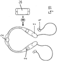
- the data processing unit 26 in the following embodiments is an integral part of the apparatus although it may also be part of a smart phone or other portable electronic computational device nearby, preferably by Bluetooth, where the data is processed via a predetermined algorithm or protocol, or connected to the apparatus via a short range wifi or by wire, depending on the activity of the user as shown in Figure 2 .
- the data processing unit 26 is thus connected to the actuator and sensor and comprises and an algorithm which determines the frequency rhythm output to the actuator based on the measured heart rate, breathing rate and calculated heart rate variability.
- the graph shows the calculation of heart rate variability based upon the measured parameters of the heart rate and the breathing rate.
- the heart rate variability is calculated by measuring the peak to peak time between each heat between.
- the heart rate variability can be calculated by measuring amplitude of each beat and calculating the difference in amplitude between one beat and the next.
- the heart signals and breathing signals can also be sensed by means of one or more microphones.
- FIG 3 shows an enlarged view of the components of the pendent 5, which includes the vibrator 2, including the vibration actuation means 27, biopotential sensor 1 and battery 16 are all contained in a single disc shaped unit.
- This implementation of the first embodiment also includes a wireless transceiver device 24, a resonance casing 22 and a contact pad 23.
- the biopotential sensor 1, includes data processing means 26 which converts the sensed parameters, such as the heart and/or breath signals into the heart rate variability value.
- FIGs 4 and 5 show a third embodiment in which the vibrators 2 and biopotential sensors 1 are held in place by a smart vest 7.
- the main apparatus body 3, including the vibration means, data processing means and battery are arranged on an elongate carrier 6 which is attached to the vest 7. The attachment may be by sewing in or incorporating the carrier 6 into the thread of the vest 7.
- biopotential sensors 1 located approximately in contact with the sternum, rib cage and spinal column.
- vibrators 2 located approximately in contact with the sternum, ribcage and spinal column.
- This embodiment includes stretch receptors 18 located on the lateral sides of the smart vest 7 to measure ventilation or respiration rate and along the spinal column and back muscles of the smart vest 7 to measure posture and movement.
- the smart vest 7 also includes a battery pack 16 and Bluetooth communicator 17. All components of the smart vest 7 are held in place by the knitted fibres of an article ofclothing.
- Figure 6 shows a further aspect of the embodiment of Figure 4 and 5 , with the apparatus body 3 arranged for attachment to an existing garment 7, in this case being a brassier. This allows the apparatus to be ideally located against the sternum of the user.
- Figure 7 shows an enlarged view of the apparatus body 3 of the embodiment of Fig. 5 in both front and perspective views showing clip attachment means 6a which is used for releasably attached, and removing the apparatus body from the garment. This would typically be required so the body can be attached for periods of use and removed after use or to wash the garment.
- FIG. 8 a further embodiment is shown in which the main apparatus body 3 is supported on a carrier member 6 which is in turn attached to the garment.
- the carrier member can be used as a support for other components of the apparatus such as sensors 1, or actuators 2.
- Figure 9 shows the embodiment of Figure 8 attached to a garment, the garment being a brassier.
- Figure 9a shows a further embodiment with an additional sensor 1 attached to the main apparatus body 3 by a short wire 21.
- Figure 10 shows an apparatus not according to the invention which includes a neck band 8.
- This neck band 8 is preferably located around the user's neck with the biopotential sensors 1 and electrical stimulators in contact with the carotid sinus of the user, with the purpose of stimulating the vagus nerve.
- This embodiment also includes vibrating elements 2 located along the length of the band 8.
- This neck band 8 is located around the user's neck such that the biopotential sensors 1 and the vibrating elements 2 in contact with the clavicular bone of the user, with the purpose of producing bone conduction stimulation into the thoracic region.
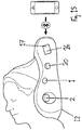
- This embodiment also includes vibrating elements 2 located at the base of the skull and headphones for audio feedback.
- Figure 11 shows a further apparatus not according to the invention in which a headphone 4, a vibrator 2 and an ear lobe clip electrode 15 are all included in a biometric earclip 10.
- This biometric ear clip is preferably attached to the user's ear via the earlobe clip electrode 15 and the headphone 4.
- Figure 12 shows a further apparatus not according to the present invention which includes a smart headphone 11 comprising a vibrator or vibration actuator 2, a sound inducer also referred to as a headphone 4 and an earlobe clip electrode 15.
- a smart headphone 11 comprising a vibrator or vibration actuator 2, a sound inducer also referred to as a headphone 4 and an earlobe clip electrode 15.
- This embodiment is preferably placed in the user's ear with the earlobe clip electrode 15 attached to the earlobe.
- Figure 13 and 14 show a further apparatus not according to the present invention which is a mat 13 which includes a number of vibrating elements 2, at least one biopotential sensor 1 and at least one speaker 3. These are arranged in a pre-determined pattern and number of each either on the surface of the mat or preferably embedded within the structure of the mat material to produce a smooth surface for resting on. The user preferably lies down on this mat to use the invention.
- the mat can be rolled up for portability.
- Figure 15 shows another apparatus not according to the present invention which includes a sleep pillow 12 comprising a vibrating element 2, a biopotential sensor 1 and bone conduction speakers 20. These are preferably in contact with the user's head and neck during use.
Landscapes
- Health & Medical Sciences (AREA)
- Life Sciences & Earth Sciences (AREA)
- Engineering & Computer Science (AREA)
- Public Health (AREA)
- General Health & Medical Sciences (AREA)
- Medical Informatics (AREA)
- Veterinary Medicine (AREA)
- Animal Behavior & Ethology (AREA)
- Pathology (AREA)
- Biomedical Technology (AREA)
- Physics & Mathematics (AREA)
- Heart & Thoracic Surgery (AREA)
- Molecular Biology (AREA)
- Surgery (AREA)
- Biophysics (AREA)
- Physiology (AREA)
- Psychiatry (AREA)
- Cardiology (AREA)
- Psychology (AREA)
- Developmental Disabilities (AREA)
- Child & Adolescent Psychology (AREA)
- Social Psychology (AREA)
- Hospice & Palliative Care (AREA)
- Pulmonology (AREA)
- Epidemiology (AREA)
- Biodiversity & Conservation Biology (AREA)
- Physical Education & Sports Medicine (AREA)
- Pain & Pain Management (AREA)
- Educational Technology (AREA)
- Rehabilitation Therapy (AREA)
- Computer Vision & Pattern Recognition (AREA)
- Databases & Information Systems (AREA)
- Primary Health Care (AREA)
- Optics & Photonics (AREA)
- Artificial Intelligence (AREA)
- Data Mining & Analysis (AREA)
- Signal Processing (AREA)
- Measuring Pulse, Heart Rate, Blood Pressure Or Blood Flow (AREA)
- Measurement And Recording Of Electrical Phenomena And Electrical Characteristics Of The Living Body (AREA)
- Percussion Or Vibration Massage (AREA)
Description
- Wearable biometric devices are growing in popularity among health conscious technology users. The ability to measure, track and evaluate health indicating variables over a long period of time is a useful tool in gaining insight in to a user's overall health. These biometric devices are often accompanied with software for processing data into fitness information. This information can be displayed as a graph over time or measured against other variables to give health advice such as "eat less" or "run more". Current collectable data includes heart rate, step count, distance travelled, travel speed and oxygen saturation.
- However, the current collectable data.is a crude measurement of overall health. It is restricted to a very narrow understanding of the health of the user.
- The current biometric devices give a very poor indication of overall wellbeing and mental state.
- Mindfulness has revolutionised the practice of psychotherapy, meditation and self-awareness and has become a common method for aiding in wellbeing and stress alleviation. These therapies however, are often time consuming and can often take years to learn how to do correctly.
- According to Yuval Noah Harari (author of Sapiens: A Brief History of Humankind) and Daniel Kahneman (founder of Behavioral Economics, author of Thinking, Fast and Slow), human beings have evolved to be made happy by one thing and one thing only - pleasant physical sensations in their bodies.
- According to Daniel J Seigal, neuroscientist, Mindfulness promotes the nine middle prefrontal brain functions:
- 1. Bodily regulation
- 2. Attunement
- 3. Emotional balance
- 4. Fear modulation
- 5. Flexibility of response
- 6. Insight
- 7. Empathy
- 8. Morality
- 9. Intuition
- On neural plasticity: "Repeated firing increases synaptic linkages and may lay down myelin, as we become an expert in the skill of knowing the inner world. We can create this repeated firing, coupled with a close focus of attention and sense of emotional engagement, as we voluntarily engage in Mindfulness practice on a regular basis".
- The health markers that are most useful in predicting mental health, stress resilience are: heart rate variability, subjective wellbeing, vagal tone, autonomic resilience and low frequency brain waves such as alpha, theta and delta waves.
- Accordingly the present invention aims to assist users in their relaxation and meditation techniques.
- According to the invention there is provided an apparatus for aiding the self-regulation of stress according to
Claim 1. - Several embodiments of the invention will now be described in references to the appended figures, in which.
-
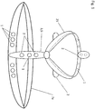
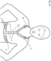
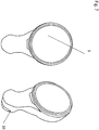
Figure 1 shows a first embodiment of the invention, - Figure la shows the embodiment of
Figure 1 worn on a user, -
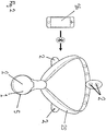
Figure 2 shows a further implementation of the embodiment ofFigure 1 , -
Figure 2a shows a graph of measured heart rate, -
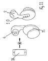
Figure 3 shows an enlarged and exploded perspective view of the components of the first embodiment of the invention, -
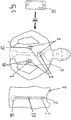
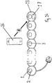
Figure 4 shows a front view of a second embodiment of the present invention, -
Figure 5 shows a front view of a third embodiment of the present invention. -
Figure 6 shows a front view of a fourth embodiment of the present invention. -
Figure 7 shows enlarged views of the apparatus ofFigure 6 . -
Figure 8 shows a front view of a further embodiment to the embodiment ofFigure 6 , -
Figure 9 shows a front view of the embodiment ofFigure 8 attached to a garment, -
Figure 9a shows a further implementation of the embodiment ofFigure 6 , -
Figure 9b shows an example not according the the invention -
Figure 10 shows an above view of an apparatus for aiding the self-regulation of stress, not according to the present invention, -
Figure 11 shows a side view of an apparatus for aiding the self-regulation of stress, not according to the present invention, -
Figure 12 shows a side view of an apparatus for aiding the self-regulation of stress, not according to the present invention, -
Figure 13 shows an above view of an apparatus for aiding the self-regulation of stress, not according to the present invention, -
Figure 14 shows a cross-section view of the disclosure ofFigure 13 , -
Figure 15 shows a cross-section view of an apparatus for aiding the self-regulation of stress, not according to the invention. - The figures disclose various apparatus for-regulating biological rhythms and assisting meditation, each comprising at least one vibratable element and a means of inducing vibration in the vibratable element at varying frequencies of vibration. Also included in this main embodiment is at least one heart rate monitoring means and a breathing rate monitoring means, and a data processing means. The data processing means includes means for calculating the heart rate variability based on the heart rate measurement and the breathing rate measurement and a means of determining a vibration rhythm, based on the calculated heart rate variability, including vibrations of at least two frequencies, which is induced in the vibratable element.
- By this means it is possible to provide passive non-visual biofeedback, distinguishing it from and in contrast to classical meditation and neuro/biofeedback based approaches that involve following a visual or simple audio cue. The use of passive neuromodulation allows the brainstem (where the vagus nerve originates) to receive signals directly and bypasses the frontal lobe, thus eliminating obstruction of the re-training process by the logical brain i.e. limbic vs frontal lobe psychology.
- Referring specifically to the Figures, the apparatus includes a heart signal monitor, a breathing signal monitor, a
data processing unit 26, and an actuator 27, which comprises avibratable element 2 and a device for creating vibrations. Many of the below embodiments will include at least onebiopotential electrode 1, which is used for sensing the heat and breathing signals. Some embodiments include other sensors. - The data processing unit calculates a stress indication value based on a time sequence of heart signals and breathing signals as shown in
Figure 3a . In this embodiment the stress indication value is derived solely from the heart signals. This is done by deriving the heart variability rate (HRV), which itself is calculated from a series of derived RR intervals. This HRV is an indication of the vagal tone which is an important factor in determining the stress indication value. These calculated values are used to generate a correspond vibration rhythm and are continuously being generated as the measurements are continuously made to form a feedback loop, such that a change in the heart rate variability of the user will generate a change in the sequence and/or frequency of vibrations. - The vibrations generated are infrasonic, being preferably less than about 50 hertz. These vibrations are generated directly by a vibratable element vibrating at the required frequency. Best results have been determined with infrasonic vibrations of less than 30 hertz.
- Biological rhythms are defined in the art as neuronal rhythms such as measured by electroencephalogram (EEG), heart rate and variability as measured by electrocardiogram (ECG), basal electrical rhythm of the gastrointestinal tract, respiration rate, vagal tone as expressed by heart rate variability and further measureable bodily rhythms. The apparatus detects signals of these rhythms and generates a vibrational rhythm accordingly, based on some predetermined criteria and also based on data gathered during the sensing and feedback process.
- The data processing means is programmed to select from a variety of rhythms from a data storage means and to manage the feedback process such that if a particular rhythm is not having a positive effect on the stress indication value, then an alternative rhythm will be selected, until a selected rhythm does have a positive effect in reducing the stress indicator value. The data storage means also include means of storing the identity of a particular user and the rhythms that have been effective in reducing the stress indication value for that particular user so that these rhythms can be prioritised on subsequent uses of the apparatus.
- In the implementation of this first embodiment of the present invention, as shown in
Figures 1 and1a , thebiopotential sensors 1 are positioned around the circumference of aneck pendant 5 and around the circumference of the body harness including achest band 7a with themain apparatus body 3 including the vibrating means 2 positioned approximately in the centre of the neck pendant. Theneck pendant 5 includes body contacting surface which is preferably in contact with the user's sternum so that the vibration can be transferred via bone conduction. There arefurther vibrators 2 positioned around thelanyard 25 approximately in contact with the clavicle bone, occipital bone and cranial vertebrae. Thebiopotential sensors 1 measure the skin surface electrical potential, these can be used to measure the heart rate and the breathing rate from which the heart rate variability is calculated providing an indication of the cardiac vagal tone. Thesensors 1 andvibrators 2 are in good electrical and vibrational contact preferably through the use ofdisposable hydrogel pads 23 or just through careful design of the harness. These variables are then transmitted either wirelessly or by wire along the lanyard orneck band data processing unit 26 located with themain body 3. - The
data processing unit 26 then determines the sequence of vibration rhythm. As well as infrasonic vibrations, audible sound frequencies,.electrical or other stimulation may also be used to alter or maintain the currently measured biometrics. This is an ongoing process and the sequence of frequencies are changeable dependent of the measured state of the user. - This implementation of the first embodiment is intended to be worn around the neck. The body contacting surface which is preferably in contact with the sternum of the user transmits the vibrations through the sternum and utilises the body's excellent acoustic resonance properties of bone, fascia and aqueous body fluids and tissues to transmit and amplify the vibrations throughout the body.
- The apparatus is powered by a
battery pack 16 located in the body of theneck pendent 5. Thevibrators 2 and thesensors 1 in thelanyard 25 are electrically connected to the apparatusmain body 3 by wires located within thelanyard 25. - The
data processing unit 26 in the following embodiments is an integral part of the apparatus although it may also be part of a smart phone or other portable electronic computational device nearby, preferably by Bluetooth, where the data is processed via a predetermined algorithm or protocol, or connected to the apparatus via a short range wifi or by wire, depending on the activity of the user as shown inFigure 2 . Thedata processing unit 26 is thus connected to the actuator and sensor and comprises and an algorithm which determines the frequency rhythm output to the actuator based on the measured heart rate, breathing rate and calculated heart rate variability. - Referring now to
Fig 2a , the graph shows the calculation of heart rate variability based upon the measured parameters of the heart rate and the breathing rate. In this embodiment the heart rate variability is calculated by measuring the peak to peak time between each heat between. Alternatively the heart rate variability can be calculated by measuring amplitude of each beat and calculating the difference in amplitude between one beat and the next. - The heart signals and breathing signals can also be sensed by means of one or more microphones.
-
Figure 3 shows an enlarged view of the components of the pendent 5, which includes thevibrator 2, including the vibration actuation means 27,biopotential sensor 1 andbattery 16 are all contained in a single disc shaped unit. This implementation of the first embodiment also includes awireless transceiver device 24, aresonance casing 22 and acontact pad 23. Thebiopotential sensor 1, includes data processing means 26 which converts the sensed parameters, such as the heart and/or breath signals into the heart rate variability value. -
Figures 4 and5 show a third embodiment in which thevibrators 2 andbiopotential sensors 1 are held in place by asmart vest 7. Themain apparatus body 3, including the vibration means, data processing means and battery are arranged on anelongate carrier 6 which is attached to thevest 7. The attachment may be by sewing in or incorporating thecarrier 6 into the thread of thevest 7. In the implementation ofFigure 5 there arebiopotential sensors 1 located approximately in contact with the sternum, rib cage and spinal column. There are alsovibrators 2 located approximately in contact with the sternum, ribcage and spinal column. This embodiment includesstretch receptors 18 located on the lateral sides of thesmart vest 7 to measure ventilation or respiration rate and along the spinal column and back muscles of thesmart vest 7 to measure posture and movement. Thesmart vest 7 also includes abattery pack 16 andBluetooth communicator 17. All components of thesmart vest 7 are held in place by the knitted fibres of an article ofclothing. -
Figure 6 shows a further aspect of the embodiment ofFigure 4 and5 , with theapparatus body 3 arranged for attachment to an existinggarment 7, in this case being a brassier. This allows the apparatus to be ideally located against the sternum of the user. -
Figure 7 shows an enlarged view of theapparatus body 3 of the embodiment ofFig. 5 in both front and perspective views showing clip attachment means 6a which is used for releasably attached, and removing the apparatus body from the garment. This would typically be required so the body can be attached for periods of use and removed after use or to wash the garment. - In the embodiment of
Figure 8 a further embodiment is shown in which themain apparatus body 3 is supported on acarrier member 6 which is in turn attached to the garment. The carrier member can be used as a support for other components of the apparatus such assensors 1, oractuators 2. -
Figure 9 shows the embodiment ofFigure 8 attached to a garment, the garment being a brassier. -
Figure 9a shows a further embodiment with anadditional sensor 1 attached to themain apparatus body 3 by ashort wire 21. -
Figure 10 shows an apparatus not according to the invention which includes aneck band 8. Thisneck band 8 is preferably located around the user's neck with thebiopotential sensors 1 and electrical stimulators in contact with the carotid sinus of the user, with the purpose of stimulating the vagus nerve. This embodiment also includes vibratingelements 2 located along the length of theband 8. - This
neck band 8 is located around the user's neck such that thebiopotential sensors 1 and the vibratingelements 2 in contact with the clavicular bone of the user, with the purpose of producing bone conduction stimulation into the thoracic region. This embodiment also includes vibratingelements 2 located at the base of the skull and headphones for audio feedback. -
Figure 11 shows a further apparatus not according to the invention in which aheadphone 4, avibrator 2 and an earlobe clip electrode 15 are all included in abiometric earclip 10. - This biometric ear clip is preferably attached to the user's ear via the
earlobe clip electrode 15 and theheadphone 4. -
Figure 12 shows a further apparatus not according to the present invention which includes asmart headphone 11 comprising a vibrator orvibration actuator 2, a sound inducer also referred to as aheadphone 4 and anearlobe clip electrode 15. This embodiment is preferably placed in the user's ear with theearlobe clip electrode 15 attached to the earlobe. -
Figure 13 and14 show a further apparatus not according to the present invention which is amat 13 which includes a number of vibratingelements 2, at least onebiopotential sensor 1 and at least onespeaker 3. These are arranged in a pre-determined pattern and number of each either on the surface of the mat or preferably embedded within the structure of the mat material to produce a smooth surface for resting on. The user preferably lies down on this mat to use the invention. The mat can be rolled up for portability. -
Figure 15 shows another apparatus not according to the present invention which includes asleep pillow 12 comprising a vibratingelement 2, abiopotential sensor 1 andbone conduction speakers 20. These are preferably in contact with the user's head and neck during use. -
- 1 - Biopotential Sensor
- 2 - Vibrator
- 3 - Apparatus main body
- 4 - Headphones
- 5 - Neck Pendant
- 6 - Carrier
- 6a - Clip attachment
- 7 - Smart Vest
- 7a - Chest band
- 8 - Neck Band
- 9 - not used
- 10 - Biometric Ear Clip
- 11 - Smart Headphones
- 12 - Sleep Pillow
- 13 - Sound Mat
- 14 - Headset
- 15 - Ear Lobe Clip Electrode
- 16 - Battery pack
- 17 - Bluetooth communicator
- 18 - Stretch receptors
- 19 - Electrical Stimulators
- 20 - Bone Conduction Speakers
- 21 - Short wire
- 22 - Resonance Casing
- 23 - Hydrogel Pad
- 24 - Wireless Charging device
- 25 - Lanyard
- 26 - Data Processing Unit
- 27 - Actuator
Claims (9)
- A wearable apparatus for aiding the self-regulation of stress, comprising:at least one vibratable element and a means of inducing vibration in the vibratable element at varying frequencies of vibration;a heart signals monitoring means, anda data processing means,wherein the apparatus comprises a data storage means;the data processing means includes means for calculating a stress indicator value based on the heart signals by deriving the heart rate variability from a series of R-R intervals to provide an indication of the vagal tone which determines the stress indication value,the data processing means further including means for determining a mechanical vibration rhythm, based on the stress indicator value, that are continuously being generated to form a feedback loop, such that a change in the heart rate variability of the user will generate a change in the sequence and/or frequency of vibration including vibrations of one or more frequencies induced in the vibratable element;wherein, the data processing means is configured to select the vibration rhythm from a plurality of vibration rhythms stored in the data storage means, wherein the selected vibration rhythm is changed if it does not have the effect of reducing the stress indicator value until a selected vibration rhythm has an effect of reducing the stress indictor value, andwherein the apparatus is suitable for attaching to a garment or suspending around the neck as a pendant such that it is configured to be positioned on the sternum for transferring vibrations via bone conductions.
- An apparatus according to claim 1, characterised in that the induced vibrations are near infrasonic, being less than 30 hertz.
- An apparatus according to claim 1, characterised in that apparatus includes at least one sensor.
- An apparatus according to claim 3, characterised in that the at least one sensor includes an electric potential heart sensor.
- An apparatus according to claim 3, characterised in that the at least one sensor includes a strain sensor.
- An apparatus according to claim 3, characterised in that the at least one sensor includes a temperature sensor.
- An apparatus according to claim 3, characterised in that the at least one sensor includes a pH meter.
- An apparatus according to claim 3, characterised in that the at least one sensor includes an image sensor.
- An apparatus according to claim 1, characterised in that the induced vibrations are less than 50 hertz.
Applications Claiming Priority (2)
| Application Number | Priority Date | Filing Date | Title |
|---|---|---|---|
| GBGB1515177.2A GB201515177D0 (en) | 2015-08-26 | 2015-08-26 | An apparatus for regulating biological rhythms |
| PCT/EP2016/001429 WO2017071785A2 (en) | 2015-08-26 | 2016-08-25 | An apparatus for aiding relaxation |
Publications (2)
| Publication Number | Publication Date |
|---|---|
| EP3340866A2 EP3340866A2 (en) | 2018-07-04 |
| EP3340866B1 true EP3340866B1 (en) | 2021-04-28 |
Family
ID=54292242
Family Applications (1)
| Application Number | Title | Priority Date | Filing Date |
|---|---|---|---|
| EP16834271.5A Active EP3340866B1 (en) | 2015-08-26 | 2016-08-25 | An apparatus for aiding relaxation |
Country Status (7)
| Country | Link |
|---|---|
| US (1) | US20200245931A1 (en) |
| EP (1) | EP3340866B1 (en) |
| JP (1) | JP6898309B2 (en) |
| KR (1) | KR20180072666A (en) |
| CN (1) | CN108024732A (en) |
| GB (1) | GB201515177D0 (en) |
| WO (1) | WO2017071785A2 (en) |
Families Citing this family (11)
| Publication number | Priority date | Publication date | Assignee | Title |
|---|---|---|---|---|
| EP3618795A4 (en) * | 2017-05-05 | 2021-04-14 | Badri Amurthur | Stimulation methods and apparatus |
| EP3731922B1 (en) | 2017-10-23 | 2024-02-21 | DataFeel Inc. | Communication devices, methods, and systems |
| CN109157728B (en) * | 2018-06-25 | 2021-07-30 | 朱森标 | Method for promoting sleep by brain bone resonance and pillow |
| CN109039354B (en) * | 2018-07-30 | 2020-09-01 | 曾新晓 | Wireless signal device and wireless signal system for safety belt |
| CA3125439A1 (en) | 2019-01-04 | 2020-07-09 | Apollo Neuroscience, Inc. | Systems and methods of wave generation for transcutaneous vibration |
| CN110327037A (en) * | 2019-07-26 | 2019-10-15 | 复旦大学附属中山医院 | Heart monitoring device and cardiac monitoring method |
| JP7345825B2 (en) * | 2019-07-26 | 2023-09-19 | 株式会社oneA | Breathing sound measuring device during sleep |
| EP3881759A1 (en) * | 2020-03-19 | 2021-09-22 | Nederlandse Organisatie voor toegepast- natuurwetenschappelijk Onderzoek TNO | Fetal heart rate monitoring device and method of controlling thereof |
| USD945737S1 (en) * | 2020-05-14 | 2022-03-15 | Kristin Harding | Gemstone cage harness |
| US20210378853A1 (en) * | 2020-06-09 | 2021-12-09 | National Cheng Kung University | Wearable interface for intelligent health promotion service system |
| US11934583B2 (en) | 2020-10-30 | 2024-03-19 | Datafeel Inc. | Wearable data communication apparatus, kits, methods, and systems |
Citations (2)
| Publication number | Priority date | Publication date | Assignee | Title |
|---|---|---|---|---|
| US20040152957A1 (en) * | 2000-06-16 | 2004-08-05 | John Stivoric | Apparatus for detecting, receiving, deriving and displaying human physiological and contextual information |
| US20140077945A1 (en) * | 2012-09-14 | 2014-03-20 | Casio Computer Co., Ltd. | Biological information notifying apparatus, biological information notifying method, and computer-readable storage medium having biological information notifying program stored thereon |
Family Cites Families (16)
| Publication number | Priority date | Publication date | Assignee | Title |
|---|---|---|---|---|
| US5687244A (en) * | 1996-03-28 | 1997-11-11 | Stanton Magnetics, Inc. | Bone conduction speaker and mounting system |
| US20050131273A1 (en) * | 2003-10-16 | 2005-06-16 | Masakazu Asano | Relaxation system, relaxation method and relaxation program |
| CN101115438B (en) * | 2005-02-07 | 2010-06-16 | 皇家飞利浦电子股份有限公司 | Device for determining a stress level of a person and providing feedback on the basis of the stress level as determined |
| GB2425181B (en) * | 2005-04-14 | 2010-02-03 | Justin Pisani | Wearable physiological monitoring device |
| JP2010502333A (en) * | 2006-09-08 | 2010-01-28 | ウル・メーター・アクティーゼルスカブ | Using pain threshold measurements |
| US20080208015A1 (en) * | 2007-02-09 | 2008-08-28 | Morris Margaret E | System, apparatus and method for real-time health feedback on a mobile device based on physiological, contextual and self-monitored indicators of mental and physical health states |
| CN101663013B (en) * | 2007-05-02 | 2011-11-30 | 霜鸟良雄 | Apparatus for preventing cerebral nervous disease |
| JP4925331B2 (en) * | 2007-10-30 | 2012-04-25 | パナソニック株式会社 | Exercise assistance device |
| CN102065759B (en) * | 2008-02-22 | 2014-10-29 | 皇家飞利浦电子股份有限公司 | A system and kit for stress and relaxation management |
| WO2013059658A1 (en) * | 2011-10-19 | 2013-04-25 | Sympara Medical Inc. | Methods and devices for treating hypertension |
| CN102488501B (en) * | 2011-11-17 | 2013-04-24 | 深圳市科瑞康实业有限公司 | Physical and mental relaxation training aid and breathing guiding mode display processing method |
| NL2008359C2 (en) * | 2012-02-27 | 2013-08-28 | Nightbalance B V | Sleep posture alerting apparatus and method. |
| US9044149B2 (en) * | 2012-06-22 | 2015-06-02 | Fitbit, Inc. | Heart rate data collection |
| EP3054912B1 (en) * | 2013-10-07 | 2021-02-24 | Oy Neurosonic Finland Ltd | Method and arrangement for alleviating the stress-related sleep disorder and reducing the stress level of a person |
| WO2015118302A2 (en) * | 2014-02-04 | 2015-08-13 | Team Turquoise Ltd. | Wearable apparatus |
| US20170042439A1 (en) * | 2014-02-14 | 2017-02-16 | National University Of Singapore | System, device and methods for brainwave-based technologies |
-
2015
- 2015-08-26 GB GBGB1515177.2A patent/GB201515177D0/en not_active Ceased
-
2016
- 2016-08-25 JP JP2018510847A patent/JP6898309B2/en active Active
- 2016-08-25 CN CN201680047511.6A patent/CN108024732A/en active Pending
- 2016-08-25 US US15/755,480 patent/US20200245931A1/en active Pending
- 2016-08-25 WO PCT/EP2016/001429 patent/WO2017071785A2/en active Application Filing
- 2016-08-25 KR KR1020187006559A patent/KR20180072666A/en unknown
- 2016-08-25 EP EP16834271.5A patent/EP3340866B1/en active Active
Patent Citations (2)
| Publication number | Priority date | Publication date | Assignee | Title |
|---|---|---|---|---|
| US20040152957A1 (en) * | 2000-06-16 | 2004-08-05 | John Stivoric | Apparatus for detecting, receiving, deriving and displaying human physiological and contextual information |
| US20140077945A1 (en) * | 2012-09-14 | 2014-03-20 | Casio Computer Co., Ltd. | Biological information notifying apparatus, biological information notifying method, and computer-readable storage medium having biological information notifying program stored thereon |
Also Published As
| Publication number | Publication date |
|---|---|
| JP6898309B2 (en) | 2021-07-07 |
| EP3340866A2 (en) | 2018-07-04 |
| US20200245931A1 (en) | 2020-08-06 |
| WO2017071785A3 (en) | 2017-06-08 |
| JP2018531056A (en) | 2018-10-25 |
| KR20180072666A (en) | 2018-06-29 |
| CN108024732A (en) | 2018-05-11 |
| WO2017071785A2 (en) | 2017-05-04 |
| GB201515177D0 (en) | 2015-10-07 |
Similar Documents
| Publication | Publication Date | Title |
|---|---|---|
| EP3340866B1 (en) | An apparatus for aiding relaxation | |
| US20240042198A1 (en) | Multifunctional closed loop neuro feedback stimulating device and methods thereof | |
| US10532211B2 (en) | Method and system for neuromodulation and stimulation | |
| JP7352614B2 (en) | Neurostimulation device and method | |
| JP2018531056A6 (en) | Equipment for assisting relaxation | |
| AU2018226818B2 (en) | Methods and systems for modulating stimuli to the brain with biosensors | |
| JP6606105B2 (en) | System and method for peripheral nerve stimulation for treating tremor | |
| US8021299B2 (en) | Correlating a non-polysomnographic physiological parameter set with sleep states | |
| US20160228640A1 (en) | Method and system for interacting with an environment | |
| US20190099582A1 (en) | Sleep performance system and method of use | |
| JP2017524396A5 (en) | ||
| WO2008096307A1 (en) | Sleep management | |
| CN113473910A (en) | Sleep monitoring system and method | |
| WO2022221858A2 (en) | Auricular device for nerve stimulation and methods of operating same | |
| US20240131340A1 (en) | Systems and methods for adjusting a neuromodulation therapy based on physiological inputs | |
| EP4360696A1 (en) | Systems for adjusting a neuromodulation therapy based on physiological inputs | |
| US20230321436A1 (en) | Medical device for stimulating neurons of a patient to suppress a pathologically synchronous activity thereof |
Legal Events
| Date | Code | Title | Description |
|---|---|---|---|
| STAA | Information on the status of an ep patent application or granted ep patent |
Free format text: STATUS: UNKNOWN |
|
| STAA | Information on the status of an ep patent application or granted ep patent |
Free format text: STATUS: THE INTERNATIONAL PUBLICATION HAS BEEN MADE |
|
| PUAI | Public reference made under article 153(3) epc to a published international application that has entered the european phase |
Free format text: ORIGINAL CODE: 0009012 |
|
| STAA | Information on the status of an ep patent application or granted ep patent |
Free format text: STATUS: REQUEST FOR EXAMINATION WAS MADE |
|
| 17P | Request for examination filed |
Effective date: 20180216 |
|
| AK | Designated contracting states |
Kind code of ref document: A2 Designated state(s): AL AT BE BG CH CY CZ DE DK EE ES FI FR GB GR HR HU IE IS IT LI LT LU LV MC MK MT NL NO PL PT RO RS SE SI SK SM TR |
|
| AX | Request for extension of the european patent |
Extension state: BA ME |
|
| DAV | Request for validation of the european patent (deleted) | ||
| DAX | Request for extension of the european patent (deleted) | ||
| STAA | Information on the status of an ep patent application or granted ep patent |
Free format text: STATUS: EXAMINATION IS IN PROGRESS |
|
| 17Q | First examination report despatched |
Effective date: 20190523 |
|
| GRAP | Despatch of communication of intention to grant a patent |
Free format text: ORIGINAL CODE: EPIDOSNIGR1 |
|
| STAA | Information on the status of an ep patent application or granted ep patent |
Free format text: STATUS: GRANT OF PATENT IS INTENDED |
|
| RIC1 | Information provided on ipc code assigned before grant |
Ipc: A61B 5/00 20060101ALI20201020BHEP Ipc: A61B 5/16 20060101ALI20201020BHEP Ipc: A61H 23/00 20060101ALI20201020BHEP Ipc: A61B 5/08 20060101ALI20201020BHEP Ipc: A61B 5/02 20060101AFI20201020BHEP |
|
| INTG | Intention to grant announced |
Effective date: 20201113 |
|
| GRAS | Grant fee paid |
Free format text: ORIGINAL CODE: EPIDOSNIGR3 |
|
| GRAA | (expected) grant |
Free format text: ORIGINAL CODE: 0009210 |
|
| STAA | Information on the status of an ep patent application or granted ep patent |
Free format text: STATUS: THE PATENT HAS BEEN GRANTED |
|
| AK | Designated contracting states |
Kind code of ref document: B1 Designated state(s): AL AT BE BG CH CY CZ DE DK EE ES FI FR GB GR HR HU IE IS IT LI LT LU LV MC MK MT NL NO PL PT RO RS SE SI SK SM TR |
|
| REG | Reference to a national code |
Ref country code: GB Ref legal event code: FG4D |
|
| REG | Reference to a national code |
Ref country code: CH Ref legal event code: EP |
|
| REG | Reference to a national code |
Ref country code: AT Ref legal event code: REF Ref document number: 1386178 Country of ref document: AT Kind code of ref document: T Effective date: 20210515 |
|
| REG | Reference to a national code |
Ref country code: DE Ref legal event code: R096 Ref document number: 602016057052 Country of ref document: DE |
|
| REG | Reference to a national code |
Ref country code: IE Ref legal event code: FG4D |
|
| REG | Reference to a national code |
Ref country code: LT Ref legal event code: MG9D |
|
| REG | Reference to a national code |
Ref country code: AT Ref legal event code: MK05 Ref document number: 1386178 Country of ref document: AT Kind code of ref document: T Effective date: 20210428 |
|
| PG25 | Lapsed in a contracting state [announced via postgrant information from national office to epo] |
Ref country code: LT Free format text: LAPSE BECAUSE OF FAILURE TO SUBMIT A TRANSLATION OF THE DESCRIPTION OR TO PAY THE FEE WITHIN THE PRESCRIBED TIME-LIMIT Effective date: 20210428 Ref country code: FI Free format text: LAPSE BECAUSE OF FAILURE TO SUBMIT A TRANSLATION OF THE DESCRIPTION OR TO PAY THE FEE WITHIN THE PRESCRIBED TIME-LIMIT Effective date: 20210428 Ref country code: NL Free format text: LAPSE BECAUSE OF FAILURE TO SUBMIT A TRANSLATION OF THE DESCRIPTION OR TO PAY THE FEE WITHIN THE PRESCRIBED TIME-LIMIT Effective date: 20210428 Ref country code: AT Free format text: LAPSE BECAUSE OF FAILURE TO SUBMIT A TRANSLATION OF THE DESCRIPTION OR TO PAY THE FEE WITHIN THE PRESCRIBED TIME-LIMIT Effective date: 20210428 Ref country code: BG Free format text: LAPSE BECAUSE OF FAILURE TO SUBMIT A TRANSLATION OF THE DESCRIPTION OR TO PAY THE FEE WITHIN THE PRESCRIBED TIME-LIMIT Effective date: 20210728 Ref country code: HR Free format text: LAPSE BECAUSE OF FAILURE TO SUBMIT A TRANSLATION OF THE DESCRIPTION OR TO PAY THE FEE WITHIN THE PRESCRIBED TIME-LIMIT Effective date: 20210428 |
|
| PG25 | Lapsed in a contracting state [announced via postgrant information from national office to epo] |
Ref country code: IS Free format text: LAPSE BECAUSE OF FAILURE TO SUBMIT A TRANSLATION OF THE DESCRIPTION OR TO PAY THE FEE WITHIN THE PRESCRIBED TIME-LIMIT Effective date: 20210828 Ref country code: LV Free format text: LAPSE BECAUSE OF FAILURE TO SUBMIT A TRANSLATION OF THE DESCRIPTION OR TO PAY THE FEE WITHIN THE PRESCRIBED TIME-LIMIT Effective date: 20210428 Ref country code: GR Free format text: LAPSE BECAUSE OF FAILURE TO SUBMIT A TRANSLATION OF THE DESCRIPTION OR TO PAY THE FEE WITHIN THE PRESCRIBED TIME-LIMIT Effective date: 20210729 Ref country code: SE Free format text: LAPSE BECAUSE OF FAILURE TO SUBMIT A TRANSLATION OF THE DESCRIPTION OR TO PAY THE FEE WITHIN THE PRESCRIBED TIME-LIMIT Effective date: 20210428 Ref country code: RS Free format text: LAPSE BECAUSE OF FAILURE TO SUBMIT A TRANSLATION OF THE DESCRIPTION OR TO PAY THE FEE WITHIN THE PRESCRIBED TIME-LIMIT Effective date: 20210428 Ref country code: PT Free format text: LAPSE BECAUSE OF FAILURE TO SUBMIT A TRANSLATION OF THE DESCRIPTION OR TO PAY THE FEE WITHIN THE PRESCRIBED TIME-LIMIT Effective date: 20210830 Ref country code: NO Free format text: LAPSE BECAUSE OF FAILURE TO SUBMIT A TRANSLATION OF THE DESCRIPTION OR TO PAY THE FEE WITHIN THE PRESCRIBED TIME-LIMIT Effective date: 20210728 Ref country code: PL Free format text: LAPSE BECAUSE OF FAILURE TO SUBMIT A TRANSLATION OF THE DESCRIPTION OR TO PAY THE FEE WITHIN THE PRESCRIBED TIME-LIMIT Effective date: 20210428 |
|
| REG | Reference to a national code |
Ref country code: NL Ref legal event code: MP Effective date: 20210428 |
|
| PG25 | Lapsed in a contracting state [announced via postgrant information from national office to epo] |
Ref country code: SK Free format text: LAPSE BECAUSE OF FAILURE TO SUBMIT A TRANSLATION OF THE DESCRIPTION OR TO PAY THE FEE WITHIN THE PRESCRIBED TIME-LIMIT Effective date: 20210428 Ref country code: SM Free format text: LAPSE BECAUSE OF FAILURE TO SUBMIT A TRANSLATION OF THE DESCRIPTION OR TO PAY THE FEE WITHIN THE PRESCRIBED TIME-LIMIT Effective date: 20210428 Ref country code: DK Free format text: LAPSE BECAUSE OF FAILURE TO SUBMIT A TRANSLATION OF THE DESCRIPTION OR TO PAY THE FEE WITHIN THE PRESCRIBED TIME-LIMIT Effective date: 20210428 Ref country code: CZ Free format text: LAPSE BECAUSE OF FAILURE TO SUBMIT A TRANSLATION OF THE DESCRIPTION OR TO PAY THE FEE WITHIN THE PRESCRIBED TIME-LIMIT Effective date: 20210428 Ref country code: EE Free format text: LAPSE BECAUSE OF FAILURE TO SUBMIT A TRANSLATION OF THE DESCRIPTION OR TO PAY THE FEE WITHIN THE PRESCRIBED TIME-LIMIT Effective date: 20210428 Ref country code: ES Free format text: LAPSE BECAUSE OF FAILURE TO SUBMIT A TRANSLATION OF THE DESCRIPTION OR TO PAY THE FEE WITHIN THE PRESCRIBED TIME-LIMIT Effective date: 20210428 Ref country code: RO Free format text: LAPSE BECAUSE OF FAILURE TO SUBMIT A TRANSLATION OF THE DESCRIPTION OR TO PAY THE FEE WITHIN THE PRESCRIBED TIME-LIMIT Effective date: 20210428 |
|
| REG | Reference to a national code |
Ref country code: DE Ref legal event code: R097 Ref document number: 602016057052 Country of ref document: DE |
|
| REG | Reference to a national code |
Ref country code: DE Ref legal event code: R119 Ref document number: 602016057052 Country of ref document: DE |
|
| PLBE | No opposition filed within time limit |
Free format text: ORIGINAL CODE: 0009261 |
|
| STAA | Information on the status of an ep patent application or granted ep patent |
Free format text: STATUS: NO OPPOSITION FILED WITHIN TIME LIMIT |
|
| REG | Reference to a national code |
Ref country code: CH Ref legal event code: PL |
|
| PG25 | Lapsed in a contracting state [announced via postgrant information from national office to epo] |
Ref country code: MC Free format text: LAPSE BECAUSE OF FAILURE TO SUBMIT A TRANSLATION OF THE DESCRIPTION OR TO PAY THE FEE WITHIN THE PRESCRIBED TIME-LIMIT Effective date: 20210428 |
|
| 26N | No opposition filed |
Effective date: 20220131 |
|
| REG | Reference to a national code |
Ref country code: BE Ref legal event code: MM Effective date: 20210831 |
|
| GBPC | Gb: european patent ceased through non-payment of renewal fee |
Effective date: 20210825 |
|
| PG25 | Lapsed in a contracting state [announced via postgrant information from national office to epo] |
Ref country code: LI Free format text: LAPSE BECAUSE OF NON-PAYMENT OF DUE FEES Effective date: 20210831 Ref country code: CH Free format text: LAPSE BECAUSE OF NON-PAYMENT OF DUE FEES Effective date: 20210831 |
|
| PG25 | Lapsed in a contracting state [announced via postgrant information from national office to epo] |
Ref country code: IS Free format text: LAPSE BECAUSE OF FAILURE TO SUBMIT A TRANSLATION OF THE DESCRIPTION OR TO PAY THE FEE WITHIN THE PRESCRIBED TIME-LIMIT Effective date: 20210828 Ref country code: AL Free format text: LAPSE BECAUSE OF FAILURE TO SUBMIT A TRANSLATION OF THE DESCRIPTION OR TO PAY THE FEE WITHIN THE PRESCRIBED TIME-LIMIT Effective date: 20210428 Ref country code: LU Free format text: LAPSE BECAUSE OF NON-PAYMENT OF DUE FEES Effective date: 20210825 |
|
| REG | Reference to a national code |
Ref country code: DE Ref legal event code: R073 Ref document number: 602016057052 Country of ref document: DE |
|
| REG | Reference to a national code |
Ref country code: GB Ref legal event code: S28 Free format text: APPLICATION FILED |
|
| PG25 | Lapsed in a contracting state [announced via postgrant information from national office to epo] |
Ref country code: IT Free format text: LAPSE BECAUSE OF FAILURE TO SUBMIT A TRANSLATION OF THE DESCRIPTION OR TO PAY THE FEE WITHIN THE PRESCRIBED TIME-LIMIT Effective date: 20210428 Ref country code: IE Free format text: LAPSE BECAUSE OF NON-PAYMENT OF DUE FEES Effective date: 20210825 Ref country code: GB Free format text: LAPSE BECAUSE OF NON-PAYMENT OF DUE FEES Effective date: 20210825 Ref country code: FR Free format text: LAPSE BECAUSE OF NON-PAYMENT OF DUE FEES Effective date: 20210831 Ref country code: DE Free format text: LAPSE BECAUSE OF NON-PAYMENT OF DUE FEES Effective date: 20220301 Ref country code: BE Free format text: LAPSE BECAUSE OF NON-PAYMENT OF DUE FEES Effective date: 20210831 |
|
| REG | Reference to a national code |
Ref country code: GB Ref legal event code: S28 Free format text: RESTORATION ALLOWED Effective date: 20220805 |
|
| PG25 | Lapsed in a contracting state [announced via postgrant information from national office to epo] |
Ref country code: FR Free format text: LAPSE BECAUSE OF NON-PAYMENT OF DUE FEES Effective date: 20210831 |
|
| PGRI | Patent reinstated in contracting state [announced from national office to epo] |
Ref country code: FR Effective date: 20221012 |
|
| REG | Reference to a national code |
Ref country code: DE Ref legal event code: R074 Ref document number: 602016057052 Country of ref document: DE |
|
| PG25 | Lapsed in a contracting state [announced via postgrant information from national office to epo] |
Ref country code: HU Free format text: LAPSE BECAUSE OF FAILURE TO SUBMIT A TRANSLATION OF THE DESCRIPTION OR TO PAY THE FEE WITHIN THE PRESCRIBED TIME-LIMIT; INVALID AB INITIO Effective date: 20160825 |
|
| PG25 | Lapsed in a contracting state [announced via postgrant information from national office to epo] |
Ref country code: CY Free format text: LAPSE BECAUSE OF FAILURE TO SUBMIT A TRANSLATION OF THE DESCRIPTION OR TO PAY THE FEE WITHIN THE PRESCRIBED TIME-LIMIT Effective date: 20210428 |
|
| PG25 | Lapsed in a contracting state [announced via postgrant information from national office to epo] |
Ref country code: DE Free format text: LAPSE BECAUSE OF NON-PAYMENT OF DUE FEES Effective date: 20220301 |
|
| PGRI | Patent reinstated in contracting state [announced from national office to epo] |
Ref country code: DE Effective date: 20230430 |
|
| PGFP | Annual fee paid to national office [announced via postgrant information from national office to epo] |
Ref country code: GB Payment date: 20230928 Year of fee payment: 8 |
|
| PGFP | Annual fee paid to national office [announced via postgrant information from national office to epo] |
Ref country code: FR Payment date: 20230703 Year of fee payment: 8 Ref country code: DE Payment date: 20230627 Year of fee payment: 8 |
|
| PG25 | Lapsed in a contracting state [announced via postgrant information from national office to epo] |
Ref country code: MK Free format text: LAPSE BECAUSE OF FAILURE TO SUBMIT A TRANSLATION OF THE DESCRIPTION OR TO PAY THE FEE WITHIN THE PRESCRIBED TIME-LIMIT Effective date: 20210428 |