EP3340536A1 - Controlling different states of operation of an electronic device over a communication network using a control device - Google Patents
Controlling different states of operation of an electronic device over a communication network using a control device Download PDFInfo
- Publication number
- EP3340536A1 EP3340536A1 EP16205215.3A EP16205215A EP3340536A1 EP 3340536 A1 EP3340536 A1 EP 3340536A1 EP 16205215 A EP16205215 A EP 16205215A EP 3340536 A1 EP3340536 A1 EP 3340536A1
- Authority
- EP
- European Patent Office
- Prior art keywords
- control
- electronic device
- access level
- control device
- parameters
- Prior art date
- Legal status (The legal status is an assumption and is not a legal conclusion. Google has not performed a legal analysis and makes no representation as to the accuracy of the status listed.)
- Granted
Links
- 238000004891 communication Methods 0.000 title claims abstract description 58
- 238000013500 data storage Methods 0.000 claims abstract description 17
- 238000000034 method Methods 0.000 claims description 19
- 230000006870 function Effects 0.000 claims description 6
- 230000015654 memory Effects 0.000 description 30
- 230000004913 activation Effects 0.000 description 13
- 241000282326 Felis catus Species 0.000 description 12
- 238000012545 processing Methods 0.000 description 8
- 238000011156 evaluation Methods 0.000 description 7
- 230000003139 buffering effect Effects 0.000 description 4
- 238000000605 extraction Methods 0.000 description 4
- 230000010354 integration Effects 0.000 description 2
- 238000012986 modification Methods 0.000 description 2
- 230000004048 modification Effects 0.000 description 2
- 230000007812 deficiency Effects 0.000 description 1
- 238000012544 monitoring process Methods 0.000 description 1
Images


Classifications
-
- H—ELECTRICITY
- H04—ELECTRIC COMMUNICATION TECHNIQUE
- H04N—PICTORIAL COMMUNICATION, e.g. TELEVISION
- H04N7/00—Television systems
- H04N7/18—Closed-circuit television [CCTV] systems, i.e. systems in which the video signal is not broadcast
- H04N7/181—Closed-circuit television [CCTV] systems, i.e. systems in which the video signal is not broadcast for receiving images from a plurality of remote sources
-
- H—ELECTRICITY
- H04—ELECTRIC COMMUNICATION TECHNIQUE
- H04N—PICTORIAL COMMUNICATION, e.g. TELEVISION
- H04N23/00—Cameras or camera modules comprising electronic image sensors; Control thereof
- H04N23/60—Control of cameras or camera modules
- H04N23/62—Control of parameters via user interfaces
-
- H—ELECTRICITY
- H04—ELECTRIC COMMUNICATION TECHNIQUE
- H04L—TRANSMISSION OF DIGITAL INFORMATION, e.g. TELEGRAPHIC COMMUNICATION
- H04L43/00—Arrangements for monitoring or testing data switching networks
- H04L43/04—Processing captured monitoring data, e.g. for logfile generation
- H04L43/045—Processing captured monitoring data, e.g. for logfile generation for graphical visualisation of monitoring data
-
- H—ELECTRICITY
- H04—ELECTRIC COMMUNICATION TECHNIQUE
- H04M—TELEPHONIC COMMUNICATION
- H04M1/00—Substation equipment, e.g. for use by subscribers
- H04M1/72—Mobile telephones; Cordless telephones, i.e. devices for establishing wireless links to base stations without route selection
- H04M1/724—User interfaces specially adapted for cordless or mobile telephones
- H04M1/72466—User interfaces specially adapted for cordless or mobile telephones with selection means, e.g. keys, having functions defined by the mode or the status of the device
-
- G—PHYSICS
- G06—COMPUTING; CALCULATING OR COUNTING
- G06F—ELECTRIC DIGITAL DATA PROCESSING
- G06F15/00—Digital computers in general; Data processing equipment in general
- G06F15/02—Digital computers in general; Data processing equipment in general manually operated with input through keyboard and computation using a built-in program, e.g. pocket calculators
- G06F15/0208—Digital computers in general; Data processing equipment in general manually operated with input through keyboard and computation using a built-in program, e.g. pocket calculators for combination with other devices having a different main function, e.g. watches, pens
-
- G—PHYSICS
- G06—COMPUTING; CALCULATING OR COUNTING
- G06F—ELECTRIC DIGITAL DATA PROCESSING
- G06F21/00—Security arrangements for protecting computers, components thereof, programs or data against unauthorised activity
- G06F21/30—Authentication, i.e. establishing the identity or authorisation of security principals
- G06F21/31—User authentication
-
- G—PHYSICS
- G08—SIGNALLING
- G08B—SIGNALLING OR CALLING SYSTEMS; ORDER TELEGRAPHS; ALARM SYSTEMS
- G08B13/00—Burglar, theft or intruder alarms
- G08B13/18—Actuation by interference with heat, light, or radiation of shorter wavelength; Actuation by intruding sources of heat, light, or radiation of shorter wavelength
- G08B13/189—Actuation by interference with heat, light, or radiation of shorter wavelength; Actuation by intruding sources of heat, light, or radiation of shorter wavelength using passive radiation detection systems
- G08B13/194—Actuation by interference with heat, light, or radiation of shorter wavelength; Actuation by intruding sources of heat, light, or radiation of shorter wavelength using passive radiation detection systems using image scanning and comparing systems
- G08B13/196—Actuation by interference with heat, light, or radiation of shorter wavelength; Actuation by intruding sources of heat, light, or radiation of shorter wavelength using passive radiation detection systems using image scanning and comparing systems using television cameras
- G08B13/19678—User interface
- G08B13/1968—Interfaces for setting up or customising the system
-
- G—PHYSICS
- G08—SIGNALLING
- G08B—SIGNALLING OR CALLING SYSTEMS; ORDER TELEGRAPHS; ALARM SYSTEMS
- G08B13/00—Burglar, theft or intruder alarms
- G08B13/18—Actuation by interference with heat, light, or radiation of shorter wavelength; Actuation by intruding sources of heat, light, or radiation of shorter wavelength
- G08B13/189—Actuation by interference with heat, light, or radiation of shorter wavelength; Actuation by intruding sources of heat, light, or radiation of shorter wavelength using passive radiation detection systems
- G08B13/194—Actuation by interference with heat, light, or radiation of shorter wavelength; Actuation by intruding sources of heat, light, or radiation of shorter wavelength using passive radiation detection systems using image scanning and comparing systems
- G08B13/196—Actuation by interference with heat, light, or radiation of shorter wavelength; Actuation by intruding sources of heat, light, or radiation of shorter wavelength using passive radiation detection systems using image scanning and comparing systems using television cameras
- G08B13/19678—User interface
- G08B13/19686—Interfaces masking personal details for privacy, e.g. blurring faces, vehicle license plates
-
- H—ELECTRICITY
- H04—ELECTRIC COMMUNICATION TECHNIQUE
- H04L—TRANSMISSION OF DIGITAL INFORMATION, e.g. TELEGRAPHIC COMMUNICATION
- H04L67/00—Network arrangements or protocols for supporting network services or applications
- H04L67/01—Protocols
- H04L67/12—Protocols specially adapted for proprietary or special-purpose networking environments, e.g. medical networks, sensor networks, networks in vehicles or remote metering networks
- H04L67/125—Protocols specially adapted for proprietary or special-purpose networking environments, e.g. medical networks, sensor networks, networks in vehicles or remote metering networks involving control of end-device applications over a network
-
- H—ELECTRICITY
- H04—ELECTRIC COMMUNICATION TECHNIQUE
- H04N—PICTORIAL COMMUNICATION, e.g. TELEVISION
- H04N23/00—Cameras or camera modules comprising electronic image sensors; Control thereof
- H04N23/60—Control of cameras or camera modules
- H04N23/617—Upgrading or updating of programs or applications for camera control
-
- H—ELECTRICITY
- H04—ELECTRIC COMMUNICATION TECHNIQUE
- H04N—PICTORIAL COMMUNICATION, e.g. TELEVISION
- H04N23/00—Cameras or camera modules comprising electronic image sensors; Control thereof
- H04N23/60—Control of cameras or camera modules
- H04N23/66—Remote control of cameras or camera parts, e.g. by remote control devices
- H04N23/661—Transmitting camera control signals through networks, e.g. control via the Internet
-
- G—PHYSICS
- G03—PHOTOGRAPHY; CINEMATOGRAPHY; ANALOGOUS TECHNIQUES USING WAVES OTHER THAN OPTICAL WAVES; ELECTROGRAPHY; HOLOGRAPHY
- G03G—ELECTROGRAPHY; ELECTROPHOTOGRAPHY; MAGNETOGRAPHY
- G03G15/00—Apparatus for electrographic processes using a charge pattern
- G03G15/50—Machine control of apparatus for electrographic processes using a charge pattern, e.g. regulating differents parts of the machine, multimode copiers, microprocessor control
- G03G15/5016—User-machine interface; Display panels; Control console
- G03G15/502—User-machine interface; Display panels; Control console relating to the structure of the control menu, e.g. pop-up menus, help screens
-
- G—PHYSICS
- G06—COMPUTING; CALCULATING OR COUNTING
- G06F—ELECTRIC DIGITAL DATA PROCESSING
- G06F11/00—Error detection; Error correction; Monitoring
- G06F11/30—Monitoring
- G06F11/32—Monitoring with visual or acoustical indication of the functioning of the machine
-
- G—PHYSICS
- G06—COMPUTING; CALCULATING OR COUNTING
- G06F—ELECTRIC DIGITAL DATA PROCESSING
- G06F2221/00—Indexing scheme relating to security arrangements for protecting computers, components thereof, programs or data against unauthorised activity
- G06F2221/21—Indexing scheme relating to G06F21/00 and subgroups addressing additional information or applications relating to security arrangements for protecting computers, components thereof, programs or data against unauthorised activity
- G06F2221/2113—Multi-level security, e.g. mandatory access control
Definitions
- the present invention relates to controlling different states of operation of an electronic device over a communication network using a control device.
- Electronic devices such as digital network cameras connected to a communication network are used for many different applications. Examples of applications are monitoring and surveillance applications.
- an electronic device may be controlled over the communication network by means of a control device.
- the control device may for example be a device that is permanently connected to the communication network dedicated for the task of controlling the electronic device or a device that is temporarily connected to the communication network for controlling the electronic device.
- the control device is typically a computing device configured for running software for controlling the electronic device.
- the software is typically a Video Managing Software, VMS.
- control device may not support this new functionality.
- control devices configured to control an electronic device over a communication network.
- a method for generating and displaying a graphical control interface comprising control graphics enabling control, at a control device and over a communication network, of different states of operation and/or functions of an electronic device.
- the method comprises retrieving, at a control device, an access level of a user logged in to the control device; receiving, at the control device and from the electronic device, control parameters by which operation of the electronic device is controllable and an access level associated with each control parameter; generating, at the control device, a set of control parameters to be generated and displayed as the control graphics by, from the received control parameters, extracting the control parameters having an access level equal to or lower than the access level of the user logged in to the control device; and generating and displaying, at the control device, the control graphics of the graphical control interface based on the generated set of control parameters.
- the electronic device may be configured to send a list of control parameters to the control device.
- Each control parameter is associated with an access level needed for performing the operation of the electronic device represented by the control parameter.
- the control device is configured to present control graphics on a display, the control graphics representing control of different states of operation and/or different functions of the electronic device.
- the control device is further configured to only display control graphics representing control parameters that are associated with an access level that should be accessible by a person logged in to the control device having an appropriate access level.
- the check for which control graphics to be displayed by the control device is made before displaying the control graphics. In this way no, or very limited, updates are needed on the control device even though new functionality of the electronic device has been added.
- functionality on the electronic device may be developed without needing to change the infrastructure of existing control devices. Accordingly, costs and time related to updating existing infrastructure of one or more control devices may be reduced.
- the method may further comprise determining a technical ability of the control device, wherein the control parameters received at the control device further is associated with a technical requirement, and wherein the act of generating the set of control parameters further comprises extracting control parameters having a technical requirement corresponding to the technical ability of the control device. Accordingly, also, or instead, technical requirements of the control parameters need at the control device for performing the control of the electronic device may be taken into account when generating the set of control parameters to be displayed.
- an electronic device comprising: a data storage comprising control parameters by which operation of the electronic device are controlled and an access level associated with each control parameter; a message generating circuitry configured to generate a control setup message comprising the control parameters and associated access levels; and a network interface configured to send the control setup message over a communication network to a control device configured to control the electronic device.
- the data storage device may further comprise information of a technical requirement associated with each control parameter, and wherein the message generating circuitry is configured to generate the control setup message to further comprise the information of the technical requirement associated with each control parameter.
- the electronic device may be a digital network camera, wherein the control parameters are control parameters for controlling operation of the digital network camera.
- a control device for controlling an electronic device over a communication network.
- the control device comprising: an access level determining circuitry configured to determine an access level of a user logged in to the control device; a network interface configured to receive a control setup message from the electronic device over the communication network, the control setup message comprising control parameters by which operation of the electronic device are controlled and an access level associated with each control parameter; a control interface setup circuitry configured to generate a set of control parameters, to be displayed as control graphics representing different states of operation and/or controllable functions of the electronic device, by, from the in the control setup message received control parameters, extract control parameters having an access level equal to or lower than the access level of the user logged in to the control device; and a graphic generating circuitry configured to generate a graphical control interface comprising control graphics enabling control of different states of operation of the electronic device corresponding to the extracted control parameters.
- the control device may further comprise a display configured to display the generated graphical control interface.
- the control device may further comprise a technical ability determining circuitry configured to determine a technical ability of the control device; wherein the control setup message further comprises a technical requirement associated with each control parameter; and wherein the control interface setup circuitry is further configured to generate the set of control parameters by extracting control parameters having an access level equal to or lower than the access level of the user logged in to the control device and having technical requirement corresponding to the technical ability of the control device.
- a system comprising an electronic device and a control device for controlling the electronic device over a communication network
- the electronic device comprises: a data storage comprising control parameters by which operation of the electronic device are controlled and an access level associated with each control parameter; a message generating circuitry configured to generate a control setup message comprising the control parameters and associated access levels; and a network interface configured to send the control setup message over the communication network to the control device;
- the control device comprises: an access level determining circuitry configured to determine an access level of a user logged in to the control device; a network interface configured to receive the control setup message from the electronic device over the communication network; a control interface setup circuitry configured to generate a set of control parameters, to be displayed as control graphics representing different states of operation of the electronic device, by, from the in the control setup message received control parameters, extract control parameters having an access level equal to or lower than the access level of the user logged in to the control device; and a graphic generating circuitry configured to generate a graphical control
- Fig. 1 illustrates a system 10 comprising an electronic device 20 and a control device 30 connected to each other via a communication network 50.
- the electronic device 20 is configured to perform various operations.
- the control device 30 is configured to control operation(s) of the electronic device 20 over the communication network 50.
- the electronic device 20 comprises a data storage 21, a message generating circuitry 22 and a network interface 23.
- the data storage 21 preferably comprises one or more non-volatile memories.
- the data storage 21 comprises control parameter(s) by which operation of the electronic device may be controlled.
- the data storage 21 further comprises an access level associated with each control parameter.
- the control parameter(s) may be stored in a database.
- the database may also comprise an access level associated with each control parameter.
- the data storage 21 may comprise a database comprising the control parameter(s) and an access level associated with each control parameter.
- Each control parameter may further comprise a reference to the functionality that is activated by the activation of the control parameter.
- each control parameter may also be associated with a technical requirement of the control device 30.
- a technical requirement is a technical requirement of the control device 30 for performing the controlling of the electronic device associated with the respective control parameter.
- Non-limiting examples of a technical requirement are: existence of a loudspeaker, SVG support, Event System Integration, Text Display facilities.
- the electronic device 20 may be configured to access an external database comprising the control parameter(s), an access level associated with each control parameter, and possible other data (e.g. functionality that is activated by the activation of the control parameter and/or technical requirement of the control device 30).
- the system further comprises a server (not shown) comprising the database, the server being connected to the communication network 50.
- the electronic device 20 may hence be configured to access the database on the server via the communication network.
- An access level is a measure of what operations a user of a device may have access to control. For example, an administrator may have one access level pertaining to that she will have access to control all operations of a device, a user of a first type may have another access level pertaining to that she will have access to control a first sub-set of operations of a device, and a user of a second type may have another access level pertaining to that she will have access to control a second sub-set of operations of a device. As indicated by the world level the access levels are divided into levels. A user with a specific access level have access to control operations of a device having an access level equal to or lower than the access level of the user.
- the electronic device 20 may be a digital network camera.
- the control parameters are control parameters for controlling operation of the digital network camera.
- Non-limiting examples of control parameters are control of: wipers, auxiluaries, analytics and camera image features.
- the control of the device may be performed via one or more of: HTTP URL, CGI URL, HTTP GET Request, HTTPS GET Request, HTTP Post Request, HTTPS POST Request, Webservice Request, Json Request, Mouse Cordinates, and Joystick input.
- the message generating circuitry 22 is configured to generate a control setup message comprising the control parameter(s) and associated access level(s).
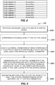
- An example of a control setup message is illustrated in Fig. 2 .
- the control setup message comprises control parameters for the device 20 and thereto associated access levels.
- the message generating circuitry 22 may be implemented as a dedicated hardware circuit and/or software module. In case of being software implemented the software may be run on a CPU 24.
- the CPU 24 may be any suitable CPU for performing digital data processing. It shall also be noted that any dedicated hardware circuit may in part comprise software portions being run on a dedicated processor or on the CPU 24.
- the message generating circuitry 22 may further be configured to generate the control setup message to further comprise the information of the technical requirement associated with each control parameter.
- the electronic device 20 may further comprise a memory 25.
- the memory 25 may be any kind of volatile or non-volatile memory. Further, the memory 25 may comprise a plurality of memory units. At least one of the plurality of memory units may be used as a buffer memory for buffering data while processing data by the CPU 24.
- the electronic device 20 is arranged to be connected to the communication network 50 via the network interface 23.
- the connection to the communication network may be wired or wireless.
- the network interface 23 may be a network port adapted to 10/100/1000 Mbps data traffic, such as an Ethernet port, a modular port being arranged to receive a modular connector, e.g., a RJ45 connector.
- a RJ45 connector port is arranged to receive a network cable, such as a twisted pair cable (e.g., of cat 5, cat 5e or cat 6).
- the I/O means of the network port may be a wireless I/O means using mobile internet communication standards (e.g., 1 G, 2G, 2.5G, 2.75G, 3G, 3.5G, 3.75G, 3.9G, 4G, 5G) or using WiFi.
- mobile internet communication standards e.g., 1 G, 2G, 2.5G, 2.75G, 3G, 3.5G, 3.75G, 3.9G, 4G, 5G
- WiFi Wireless Fidelity
- the network interface 23 is further configured to send the control setup message over the communication network 50 to the control device 30.
- the control device 30 comprises a network interface 31, an access level determining circuitry 32, a control interface setup circuitry 33 and a graphic generating circuitry 34. Any one of the access level determining circuitry 32, the control interface setup circuitry 33 and the graphic generating circuitry 34 may be implemented as a dedicated hardware circuit and/or software module. In case of being software implemented the software may be run on a CPU 35.
- the CPU 35 may be any suitable CPU for performing digital data processing. It shall also be noted that any dedicated hardware circuit may in part comprise software portions being run on a dedicated processor or on the CPU 35.
- the control device 30 may further comprise a memory 36.
- the memory 36 may be any kind of volatile or non-volatile memory. Further, the memory 36 may comprise a plurality of memory units. At least one of the plurality of memory units may be used as a buffer memory for buffering data while processing data by the CPU 35.
- the control device 30 is configured to be connected to the communication network 50 via the network interface 31.
- the connection to the communication network may be wired or wireless.
- the network interface 31 may be a network port adapted to 10/100/1000 Mbps data traffic, such as an Ethernet port, a modular port being arranged to receive a modular connector, e.g., a RJ45 connector.
- a RJ45 connector port is arranged to receive a network cable, such as a twisted pair cable (e.g., of cat 5, cat 5e or cat 6).
- the I/O means of the network port may be a wireless I/O means using mobile internet communication standards (e.g., 1 G, 2G, 2.5G, 2.75G, 3G, 3.5G, 3.75G, 3.9G, 4G, 5G) or using WiFi.
- mobile internet communication standards e.g., 1 G, 2G, 2.5G, 2.75G, 3G, 3.5G, 3.75G, 3.9G, 4G, 5G
- WiFi Wireless Fidelity
- the network interface 31 is configured to receive the control setup message from the electronic device 20 over the communication network 50.
- the access level determining circuitry 32 is configured to determine an access level of a user logged in to the control device 30.
- the control interface setup circuitry 33 is configured to get the control setup message and the access level of a user logged in to the control device 30 as input data. From these input data the control interface setup circuitry 33 is configured to generate a set of control parameters by extracting control parameters having an access level equal to or lower than the access level of the user logged in to the control device 30. With reference to the exemplified control setup message of Fig. 2 , below some examples of extraction of control parameters will be discussed. According to a first example, the user logged in to the control device 30 have the access level 3, i.e. the highest access level (this access level may e.g. be the access level of an administrator).
- the set of control parameters will comprise all the control parameters A-H, this since they are all associated with an access level equal to or lower than the access level (in this first example the access level 3) of the user logged in to the control device 30.
- the user logged in to the control device 30 have the access level 2, i.e. the middle access level (this access level may e.g. be the access level of an installer of the electronic device 20).
- the set of control parameters will comprise the control parameters A, B, D, E, F and H, this since these control parameters are associated with an access level equal to or lower than the access level (in this first example the access level 2) of the user logged in to the control device 30.
- the user logged in to the control device 30 have the access level 1, i.e. the lowest access level (this access level may e.g. be the access level of an operator of the electronic device 20).
- the set of control parameters will comprise the control parameters A, E and F, this since these control parameters are associated with an access level equal to or lower than the access level (in this first example the access level 1) of the user logged in to the control device 30.
- the set of control parameters only comprises the control parameters associated with an access level equal to or lower than the access level of the user logged in to the control device 30.
- the graphic generating circuitry 34 is configured to receive the set of control parameters generated by the control interface setup circuitry 33 as input data.
- the graphic generating circuitry 34 is further configured to generate a graphical control interface comprising control graphics for the control parameters.
- the control graphics representing control of different states of operation of the electronic device 20.
- the different states of operation correspond to the, by the control interface setup circuitry 33, extracted control parameters.
- Non-limiting examples of control graphics are: a text bar; a toggle button, a menu item and a slider. Hence, control of different states of operation of the electronic device 20 corresponding to the by the control interface setup circuitry 33 extracted control parameters are enabled.
- the control device 30 may further comprise a display 37 configured to display the graphical control interface.
- the control device 30 may further comprise a user input unit 38 configured to receive user input indicative on activation of one or more of the control graphics of the graphical control interface.
- a user input unit 38 configured to receive user input indicative on activation of one or more of the control graphics of the graphical control interface.
- Many different user input unit 38 for this purpose are known for the person skilled in the art. Non-limiting examples are a mouse, a keyboard, and a touch sensitive display.
- the control device 30 may further comprise a message generating circuitry 39.
- the message generating circuitry 39 may be implemented as a dedicated hardware circuit and/or software module. In case of being software implemented the software may be run on the CPU 35.
- the message generating circuitry 39 is configured to generate a command message.
- the message generating circuitry 39 is configured to generate the command message, in case of activation of a control graphics.
- the command message including a reference to what operation of the electronic device 20 that has been controlled by activation of the control graphics.
- the network interface 31 is then further configured to send the command message to the electronic device 20 over the communication network 50.
- the control device 30 may further comprise a technical ability determining circuitry 40.
- the technical ability determining circuitry 40 may be implemented as a dedicated hardware circuit and/or software module. In case of being software implemented the software may be run on the CPU 35.
- the technical ability determining circuitry 40 is configured to determine a technical ability of the control device 30.
- the technical ability of the control device 30 is a measure of technical features the control device 30 may perform. Non-limiting examples are that the control device 30 may display PopUP, display text and/or open an audio channel to device.
- control setup message may further comprise a technical requirement associated with each control parameter.
- the control interface setup circuitry 33 may then further be configured to generate the set of control parameters by extracting control parameters having an access level equal to or lower than the access level of the user logged in to the control device and having technical requirement corresponding to the technical ability of the control device 30.
- the control device 30 does not comprises a loudspeaker. Hence, if no loudspeaker is present at the control device 30, control graphics regarding receipt of audio at the control device may not be generated and displayed.
- the electronic device 20 is configured to send a list of control parameters to the control device 30.
- Each control parameter is associated with an access level needed for performing the operation of the electronic device 20 represented by the control parameter.
- the control device 30 is configured to present control graphics on a display, the control graphics representing control of different states of operation of the electronic device 20.
- the control device 30 is further configured to only display control graphics representing control parameters that are associated with an access level that should be accessible by a person logged in to the control device 30 having an appropriate access level. The check for which control graphics to be displayed by the control device 30 is made before displaying the control graphics.
- the control device 30 is further configured to, in case of activation of a control graphics, send a command message back to the electronic device 20.
- the command message is sent over the communication network 50.
- the command message including a reference to what operation of the electronic device 20 that has been controlled by activation of the control graphics. In this way no updates are needed on the control device 30 even though new functionality of the electronic device 20 has been added.
- a method 300 for generating and displaying a graphical control interface comprising control graphics enabling control of different states of operation of an electronic device 20 will be discussed.
- the generating and displaying is performed at a control device 30.
- the control device 30 is configured to control the electronic device 20 over a communication network 50.
- the method comprising the following acts. Retrieving S300, at the control device 30, an access level of a user logged in to the control device 30. Receiving S302, at the control device 30 and from the electronic device 20, control parameters by which operation of the electronic device 20 is controllable and an access level associated with each control parameter.
- the method may further comprise determining S301 a technical ability of the control device 30.
- the control parameters received at the control device 30 may further be associated with a technical requirement.
- the act of generating S304 the set of control parameters may further comprise extracting control parameters having a technical requirement corresponding to the technical ability of the control device 30.
- this alternative system 410 comprises an electronic device 420 and a control device 430 connected to each other via a communication network 450.
- the electronic device 420 is configured to perform various operations.
- the control device 430 is configured to control operation(s) of the electronic device 420 over the communication network 450.
- the control device 430 comprises a network interface 43, an access level determining circuitry 432 and a message generating circuitry 439.
- the control device 430 is configured to be connected to the communication network 450 via the network interface 431.
- the connection to the communication network may be wired or wireless.
- the network interface 431 may be a network port adapted to 10/100/1000 Mbps data traffic, such as an Ethernet port, a modular port being arranged to receive a modular connector, e.g., a RJ45 connector.
- a RJ45 connector port is arranged to receive a network cable, such as a twisted pair cable (e.g., of cat 5, cat 5e or cat 6).
- the I/O means of the network port may be a wireless I/O means using mobile internet communication standards (e.g., 1 G, 2G, 2.5G, 2.75G, 3G, 3.5G, 3.75G, 3.9G, 4G, 5G) or using WiFi.
- mobile internet communication standards e.g., 1 G, 2G, 2.5G, 2.75G, 3G, 3.5G, 3.75G, 3.9G, 4G, 5G
- WiFi Wireless Fidelity
- any one of the access level determining circuitry 432 and the message generating circuitry 439 may be implemented as a dedicated hardware circuit and/or software module.
- the software may be run on a CPU 435.
- the CPU 435 may be any suitable CPU for performing digital data processing.
- any dedicated hardware circuit may in part comprise software portions being run on a dedicated processor or on the CPU 435.
- the control device 430 may further comprise a memory 436.
- the memory 436 may be any kind of volatile or non-volatile memory. Further, the memory 436 may comprise a plurality of memory units. At least one of the plurality of memory units may be used as a buffer memory for buffering data while processing data by the CPU 435.
- the access level determining circuitry 432 is configured to determine an access level of a user logged in to the control device 430.
- An access level is a measure of what operations a user of a device may have access to control. Se above, for a more detailed discussion about access level(s). There are numerous techniques already known to a person skilled in the art on how to identify a user logging into a device and connecting the user to an access level, hence, these techniques will not be disclosed herein in detail.
- the message generating circuitry 439 is configured to generate an access level message.
- the access level message comprising the access level of the user logged in to the control device 430.
- the network interface 431 of the control device 430 is configured to send the access level message to the electronic device 420 over the communication network 450.
- the electronic device 420 comprises a data storage 421, a message generating circuitry 422, a network interface 423 and a control parameter evaluation circuitry 426.
- Any one of the message generating circuitry 422 and the control parameter evaluation circuitry 426 may be implemented as a dedicated hardware circuit and/or software module.
- the software may be run on a CPU 424.
- the CPU 424 may be any suitable CPU for performing digital data processing.
- any dedicated hardware circuit may in part comprise software portions being run on a dedicated processor or on the CPU 424.
- the electric device 420 may further comprise a memory 425.
- the memory 425 may be any kind of volatile or non-volatile memory. Further, the memory 425 may comprise a plurality of memory units. At least one of the plurality of memory units may be used as a buffer memory for buffering data while processing data by the CPU 424.
- the electronic device 420 is arranged to be connected to the communication network 450 via the network interface 423.
- the connection to the communication network may be wired or wireless.
- the network interface 423 may be a network port adapted to 10/100/1000 Mbps data traffic, such as an Ethernet port, a modular port being arranged to receive a modular connector, e.g., a RJ45 connector.
- a RJ45 connector port is arranged to receive a network cable, such as a twisted pair cable (e.g., of cat 5, cat 5e or cat 6).
- the I/O means of the network port may be a wireless I/O means using mobile internet communication standards (e.g., 1 G, 2G, 2.5G, 2.75G, 3G, 3.5G, 3.75G, 3.9G, 4G, 5G) or using WiFi.
- mobile internet communication standards e.g., 1 G, 2G, 2.5G, 2.75G, 3G, 3.5G, 3.75G, 3.9G, 4G, 5G
- WiFi Wireless Fidelity
- the network interface 423 of the electronic device 420 is configured to receive the access level message from the control device 430 over the communication network 450.
- the data storage 421 preferably comprises one or more non-volatile memories.
- the data storage 421 comprises control parameter(s) by which operation of the electronic device may be controlled.
- the data storage 421 further comprises and an access level associated with each control parameter.
- the control parameter(s) may be stored in a database.
- the database may also comprise an access level associated with each control parameter.
- the data storage 421 may comprise a database comprising the control parameter(s) and an access level associated with each control parameter.
- Each control parameter may further comprise a reference to the functionality that is activated by the activation of the control parameter.
- each control parameter may also be associated with a technical requirement of the control device 430.
- a technical requirement is a technical requirement of the control device 430 for performing the controlling of the electronic device associated with the respective control parameter.
- Non-limiting examples of a technical requirement are: existence of a loudspeaker, SVG support, Event System Integration, Text Display facilities.
- the electronic device 420 may be configured to access an external database comprising the control parameter(s), an access level associated with each control parameter, and possible other data (e.g. functionality that is activated by the activation of the control parameter and/or technical requirement of the control device 430).
- the system further comprises a server (not shown) comprising the database, the server being connected to the communication network 450.
- the electronic device 420 may hence be configured to access the database on the server via the communication network.
- the electronic device 420 may be a digital network camera.
- the control parameters are control parameters for controlling operation of the digital network camera.
- the control parameter evaluation circuitry 426 is configured to use the access level of the user logged in to the control device of the access level message as input data.
- the control parameter evaluation circuitry 426 is configured to, from the database, extract the control parameters having an access level equal to or lower than the access level of the user logged in to the control device 430.
- the extracted control parameters having an access level equal to or lower than the access level of the user logged in to the control device 430 forms a set of control parameters.
- the set of control parameters will comprise all the control parameters A-H, this since they are all associated with an access level equal to or lower than the access level (in this first example the access level 3) of the user logged in to the control device 430.
- the user logged in to the control device 430 have the access level 2, i.e. the middle access level (this access level may e.g. be the access level of an installer of the electronic device 420).
- the set of control parameters will comprise the control parameters A, B, D, E, F and H, this since these control parameters are associated with an access level equal to or lower than the access level (in this first example the access level 2) of the user logged in to the control device 30.
- the user logged in to the control device 30 have the access level 1, i.e. the lowest access level (this access level may e.g. be the access level of an operator of the electronic device 420).
- the set of control parameters will comprise the control parameters A, E and F, this since these control parameters are associated with an access level equal to or lower than the access level (in this first example the access level 1) of the user logged in to the control device 430.
- the set of control parameters only comprises the control parameters associated with an access level equal to or lower than the access level of the user logged in to the control device 430.
- the message generating circuitry 422 of the electronic device 420 is configured to generate a control setup message.
- the control setup message comprising the extracted set of control parameters.
- the control setup message may comprise a reference to the functionality that is activated by the activation of each of the control parameters in the set of control parameters.
- the network interface 423 of the electronic device 420 is further configured to send the control setup message to the control device 430 over the communication network 450.
- the network interface 431 of the control device 430 is further configured to receive the control setup message from the electronic device 420 over the communication network 450.
- the control device 430 further comprises a graphic generating circuitry 434.
- the graphic generating circuitry 434 may be implemented as a dedicated hardware circuit and/or software module. In case of being software implemented the software may be run on a CPU 435.
- the graphic generating circuitry 434 is configured to receive the set of control parameters of the control setup message as input data.
- the graphic generating circuitry 434 is further configured to generate a graphical control interface comprising control graphics for the control parameters of the set of control parameters.
- the control graphics representing control of different states of operation of the electronic device 420 corresponding to the extracted set of control parameters. Hence, control of different states of operation of the electronic device 420 corresponding to the extracted set of control parameters are enabled.
- the control device 430 may further comprise a display 437 configured to display the graphical control interface.
- the control device 30 may further comprise a user input unit 438 configured to receive user input indicative on activation of one or more of the control graphics of the graphical control interface.
- a user input unit 438 configured to receive user input indicative on activation of one or more of the control graphics of the graphical control interface.
- Many different user input unit 438 for this purpose are known for the person skilled in the art. Non-limiting examples are a mouse, a keyboard, and a touch sensitive display.
- the message generating circuitry 439 of the control device 430 may further be configured to generate a command message.
- the message generating circuitry 439 is configured to generate the command message, in case of activation of a control graphics.
- the command message including a reference to what operation of the electronic device 420 that has been controlled by activation of the control graphics.
- the network interface 431 of the control device 430 is then further configured to send the command message to the electronic device 420 over the communication network 450.
- the database of control parameters may further comprise a technical requirement associated with each control parameter.
- the control device 430 may further comprise a technical ability determining circuitry 440.
- the technical ability determining circuitry 440 may be implemented as a dedicated hardware circuit and/or software module. In case of being software implemented the software may be run on the CPU 435.
- the technical ability determining circuitry 440 is configured to determine a technical ability of the control device 430.
- the technical ability of the control device 430 is a measure of technical features the control device 30 may perform. Non-limiting examples are that the control device 30 may display PopUP, display text and/or open an audio channel to device.
- the message generating circuitry 439 of the control device 430 may further be configured to generate a technical ability message.
- the technical ability message comprising the technical ability of the control device 430.
- the technical ability message may be included in the access level message.
- the control parameter evaluation circuitry 426 of the electronic device 420 may then further be configured to generate the set of control parameters by in addition to extracting control parameters having an access level equal to or lower than the access level of the user logged in to the control device also taking the technical requirement of the control parameters and the technical ability of the control device 30 into consideration.
- the control parameter evaluation circuitry 426 may be configured to generate the set of control parameters by extracting control parameters having an access level equal to or lower than the access level of the user logged in to the control device 430 and having technical requirement corresponding to the technical ability of the control device 430.
- the control device 430 does not comprises a loudspeaker. Hence, if no loudspeaker is present at the control device 430, control graphics regarding receipt of audio at the control device 430 shall not be generated and hence control parameters needing a loudspeaker will not be extracted by the control parameter evaluation circuitry 426.
- the extraction of the set of control parameters may be performed in the electronic device 420.
- the access level of the user logged in to the control device 430 is received at the electronic device 420 and the act of generating the set of control parameters is performed at the electronic device 430.
- the generated set of control parameters are sent from the electronic device 420 to the control device 430 over the communication network 450. In this way no updates are needed on the control device 430 even though new functionality of the electronic device 420 has been added.
- the generation of the set of control parameters to be displayed as the control graphics of the graphical control interface may instead be solely based on the technical ability of the control device and the technical requirements of respective control parameter.
- the set of control parameters, to be displayed as control graphics representing different states of operation of the electronic device may be determined by extracting control parameters having technical requirement corresponding to the technical ability of the control device.
Landscapes
- Engineering & Computer Science (AREA)
- Signal Processing (AREA)
- Multimedia (AREA)
- Computer Networks & Wireless Communication (AREA)
- Physics & Mathematics (AREA)
- General Physics & Mathematics (AREA)
- Theoretical Computer Science (AREA)
- Human Computer Interaction (AREA)
- Data Mining & Analysis (AREA)
- Computing Systems (AREA)
- Computer Hardware Design (AREA)
- General Engineering & Computer Science (AREA)
- General Health & Medical Sciences (AREA)
- Medical Informatics (AREA)
- Health & Medical Sciences (AREA)
- Software Systems (AREA)
- Computer Security & Cryptography (AREA)
- User Interface Of Digital Computer (AREA)
- Selective Calling Equipment (AREA)
- Stored Programmes (AREA)
Abstract
Description
- The present invention relates to controlling different states of operation of an electronic device over a communication network using a control device.
- Electronic devices, such as digital network cameras connected to a communication network are used for many different applications. Examples of applications are monitoring and surveillance applications. In many applications an electronic device may be controlled over the communication network by means of a control device. The control device may for example be a device that is permanently connected to the communication network dedicated for the task of controlling the electronic device or a device that is temporarily connected to the communication network for controlling the electronic device. The control device is typically a computing device configured for running software for controlling the electronic device. In the case of the electronic device being a digital network camera the software is typically a Video Managing Software, VMS.
- However, upon updating an electronic device, connected to the communication network, with new functionality or installing a new electronic device with new functionality to the communication network, the control device may not support this new functionality. Hence, there is a need for enabling support for new functionality in control devices configured to control an electronic device over a communication network.
- It is an object to mitigate, alleviate or eliminate one or more of the above-identified deficiencies in the art and disadvantages singly or in any combination.
- According to a first aspect a method for generating and displaying a graphical control interface comprising control graphics enabling control, at a control device and over a communication network, of different states of operation and/or functions of an electronic device is provided. The method comprises retrieving, at a control device, an access level of a user logged in to the control device; receiving, at the control device and from the electronic device, control parameters by which operation of the electronic device is controllable and an access level associated with each control parameter; generating, at the control device, a set of control parameters to be generated and displayed as the control graphics by, from the received control parameters, extracting the control parameters having an access level equal to or lower than the access level of the user logged in to the control device; and generating and displaying, at the control device, the control graphics of the graphical control interface based on the generated set of control parameters.
- Accordingly, the electronic device may be configured to send a list of control parameters to the control device. Each control parameter is associated with an access level needed for performing the operation of the electronic device represented by the control parameter. Then, the control device is configured to present control graphics on a display, the control graphics representing control of different states of operation and/or different functions of the electronic device. The control device is further configured to only display control graphics representing control parameters that are associated with an access level that should be accessible by a person logged in to the control device having an appropriate access level. The check for which control graphics to be displayed by the control device is made before displaying the control graphics. In this way no, or very limited, updates are needed on the control device even though new functionality of the electronic device has been added. Hence, functionality on the electronic device may be developed without needing to change the infrastructure of existing control devices. Accordingly, costs and time related to updating existing infrastructure of one or more control devices may be reduced.
- The method may further comprise determining a technical ability of the control device, wherein the control parameters received at the control device further is associated with a technical requirement, and wherein the act of generating the set of control parameters further comprises extracting control parameters having a technical requirement corresponding to the technical ability of the control device. Accordingly, also, or instead, technical requirements of the control parameters need at the control device for performing the control of the electronic device may be taken into account when generating the set of control parameters to be displayed.
- According to a second aspect an electronic device is provided. The electronic device comprising: a data storage comprising control parameters by which operation of the electronic device are controlled and an access level associated with each control parameter; a message generating circuitry configured to generate a control setup message comprising the control parameters and associated access levels; and a network interface configured to send the control setup message over a communication network to a control device configured to control the electronic device.
- The data storage device may further comprise information of a technical requirement associated with each control parameter, and wherein the message generating circuitry is configured to generate the control setup message to further comprise the information of the technical requirement associated with each control parameter.
- The electronic device may be a digital network camera, wherein the control parameters are control parameters for controlling operation of the digital network camera.
- The above mentioned features of the method, when applicable, apply to this second aspect as well. In order to avoid undue repetition, reference is made to the above.
- According to a third aspect a control device for controlling an electronic device over a communication network is provided. The control device comprising: an access level determining circuitry configured to determine an access level of a user logged in to the control device; a network interface configured to receive a control setup message from the electronic device over the communication network, the control setup message comprising control parameters by which operation of the electronic device are controlled and an access level associated with each control parameter; a control interface setup circuitry configured to generate a set of control parameters, to be displayed as control graphics representing different states of operation and/or controllable functions of the electronic device, by, from the in the control setup message received control parameters, extract control parameters having an access level equal to or lower than the access level of the user logged in to the control device; and a graphic generating circuitry configured to generate a graphical control interface comprising control graphics enabling control of different states of operation of the electronic device corresponding to the extracted control parameters.
- The control device may further comprise a display configured to display the generated graphical control interface.
- The control device may further comprise a technical ability determining circuitry configured to determine a technical ability of the control device; wherein the control setup message further comprises a technical requirement associated with each control parameter; and wherein the control interface setup circuitry is further configured to generate the set of control parameters by extracting control parameters having an access level equal to or lower than the access level of the user logged in to the control device and having technical requirement corresponding to the technical ability of the control device.
- The above mentioned features of the method and electronic device, when applicable, apply to this third aspect as well. In order to avoid undue repetition, reference is made to the above.
- According to a forth aspect a system is provided. The system comprising an electronic device and a control device for controlling the electronic device over a communication network, wherein the electronic device comprises: a data storage comprising control parameters by which operation of the electronic device are controlled and an access level associated with each control parameter; a message generating circuitry configured to generate a control setup message comprising the control parameters and associated access levels; and a network interface configured to send the control setup message over the communication network to the control device; wherein the control device comprises: an access level determining circuitry configured to determine an access level of a user logged in to the control device; a network interface configured to receive the control setup message from the electronic device over the communication network; a control interface setup circuitry configured to generate a set of control parameters, to be displayed as control graphics representing different states of operation of the electronic device, by, from the in the control setup message received control parameters, extract control parameters having an access level equal to or lower than the access level of the user logged in to the control device; and a graphic generating circuitry configured to generate a graphical control interface comprising control graphics enabling control of different states of operation and/or functions of the electronic device corresponding to the extracted control parameters.
- The above mentioned features of the method, electronic device and control device, when applicable, apply to this fourth aspect as well. In order to avoid undue repetition, reference is made to the above.
- A further scope of applicability of the present invention will become apparent from the detailed description given below. However, it should be understood that the detailed description and specific examples, while indicating preferred embodiments of the invention, are given by way of illustration only, since various changes and modifications within the scope of the invention will become apparent to those skilled in the art from this detailed description.
- Hence, it is to be understood that this invention is not limited to the particular component parts of the device described or steps of the methods described as such device and method may vary. It is also to be understood that the terminology used herein is for purpose of describing particular embodiments only, and is not intended to be limiting. It must be noted that, as used in the specification and the appended claim, the articles "a," "an," "the," and "said" are intended to mean that there are one or more of the elements unless the context clearly dictates otherwise. Thus, for example, reference to "a unit" or "the unit" may include several devices, and the like. Furthermore, the words "comprising", "including", "containing" and similar wordings does not exclude other elements or steps.
- The above and other aspects of the present invention will now be described in more detail, with reference to appended drawings showing embodiments of the invention. The figures should not be considered limiting the invention to the specific embodiment; instead they are used for explaining and understanding the invention.
- As illustrated in the figures, the sizes of layers and regions are exaggerated for illustrative purposes and, thus, are provided to illustrate the general structures of embodiments of the present invention. Like reference numerals refer to like elements throughout.
-
Fig. 1 illustrates a system comprising an electronic device and a control device for controlling the electronic device over a communication network. -
Fig. 2 illustrates an example of a control setup message. -
Fig. 3 is a flowchart of a method for generating and displaying a graphical control interface comprising control graphics enabling control of different states of operation of an electronic device. -
Fig. 4 . illustrates an alternative system comprising an electronic device and a control device for controlling the electronic device over a communication network. -
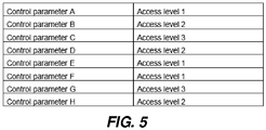
Fig. 5 illustrates an example of a control parameter database. - The present invention will now be described more fully hereinafter with reference to the accompanying drawings, in which currently preferred embodiments of the invention are shown. This invention may, however, be embodied in many different forms and should not be construed as limited to the embodiments set forth herein; rather, these embodiments are provided for thoroughness and completeness, and to fully convey the scope of the invention to the skilled person.
-
Fig. 1 illustrates asystem 10 comprising anelectronic device 20 and acontrol device 30 connected to each other via acommunication network 50. Theelectronic device 20 is configured to perform various operations. Thecontrol device 30 is configured to control operation(s) of theelectronic device 20 over thecommunication network 50. - The
electronic device 20 comprises adata storage 21, amessage generating circuitry 22 and anetwork interface 23. - The
data storage 21 preferably comprises one or more non-volatile memories. Thedata storage 21 comprises control parameter(s) by which operation of the electronic device may be controlled. Thedata storage 21 further comprises an access level associated with each control parameter. The control parameter(s) may be stored in a database. The database may also comprise an access level associated with each control parameter. Hence, thedata storage 21 may comprise a database comprising the control parameter(s) and an access level associated with each control parameter. Each control parameter may further comprise a reference to the functionality that is activated by the activation of the control parameter. - Further, each control parameter may also be associated with a technical requirement of the
control device 30. A technical requirement is a technical requirement of thecontrol device 30 for performing the controlling of the electronic device associated with the respective control parameter. Non-limiting examples of a technical requirement are: existence of a loudspeaker, SVG support, Event System Integration, Text Display facilities. - Alternatively, the
electronic device 20 may be configured to access an external database comprising the control parameter(s), an access level associated with each control parameter, and possible other data (e.g. functionality that is activated by the activation of the control parameter and/or technical requirement of the control device 30). In such alternative scenario, the system further comprises a server (not shown) comprising the database, the server being connected to thecommunication network 50. Theelectronic device 20 may hence be configured to access the database on the server via the communication network. This alternative way of accessing the control parameter(s),the access level associated with each control parameter, and possible other data from an external database of a server, is applicable to all embodiments disclosed in this disclosure. - An access level is a measure of what operations a user of a device may have access to control. For example, an administrator may have one access level pertaining to that she will have access to control all operations of a device, a user of a first type may have another access level pertaining to that she will have access to control a first sub-set of operations of a device, and a user of a second type may have another access level pertaining to that she will have access to control a second sub-set of operations of a device. As indicated by the world level the access levels are divided into levels. A user with a specific access level have access to control operations of a device having an access level equal to or lower than the access level of the user.
- The
electronic device 20 may be a digital network camera. In such case, the control parameters are control parameters for controlling operation of the digital network camera. Non-limiting examples of control parameters are control of: wipers, auxiluaries, analytics and camera image features. The control of the device may be performed via one or more of: HTTP URL, CGI URL, HTTP GET Request, HTTPS GET Request, HTTP Post Request, HTTPS POST Request, Webservice Request, Json Request, Mouse Cordinates, and Joystick input. - The
message generating circuitry 22 is configured to generate a control setup message comprising the control parameter(s) and associated access level(s). An example of a control setup message is illustrated inFig. 2 . Hence, the control setup message comprises control parameters for thedevice 20 and thereto associated access levels. Themessage generating circuitry 22 may be implemented as a dedicated hardware circuit and/or software module. In case of being software implemented the software may be run on aCPU 24. TheCPU 24 may be any suitable CPU for performing digital data processing. It shall also be noted that any dedicated hardware circuit may in part comprise software portions being run on a dedicated processor or on theCPU 24. - The
message generating circuitry 22 may further be configured to generate the control setup message to further comprise the information of the technical requirement associated with each control parameter. - The
electronic device 20 may further comprise amemory 25. Thememory 25 may be any kind of volatile or non-volatile memory. Further, thememory 25 may comprise a plurality of memory units. At least one of the plurality of memory units may be used as a buffer memory for buffering data while processing data by theCPU 24. - The
electronic device 20 is arranged to be connected to thecommunication network 50 via thenetwork interface 23. The connection to the communication network may be wired or wireless. Thus, thenetwork interface 23 may be a network port adapted to 10/100/1000 Mbps data traffic, such as an Ethernet port, a modular port being arranged to receive a modular connector, e.g., a RJ45 connector. Normally, such a RJ45 connector port is arranged to receive a network cable, such as a twisted pair cable (e.g., of cat 5, cat 5e or cat 6). Alternatively, the I/O means of the network port may be a wireless I/O means using mobile internet communication standards (e.g., 1 G, 2G, 2.5G, 2.75G, 3G, 3.5G, 3.75G, 3.9G, 4G, 5G) or using WiFi. - The
network interface 23 is further configured to send the control setup message over thecommunication network 50 to thecontrol device 30. - The
control device 30 comprises anetwork interface 31, an accesslevel determining circuitry 32, a controlinterface setup circuitry 33 and agraphic generating circuitry 34. Any one of the accesslevel determining circuitry 32, the controlinterface setup circuitry 33 and thegraphic generating circuitry 34 may be implemented as a dedicated hardware circuit and/or software module. In case of being software implemented the software may be run on aCPU 35. TheCPU 35 may be any suitable CPU for performing digital data processing. It shall also be noted that any dedicated hardware circuit may in part comprise software portions being run on a dedicated processor or on theCPU 35. - The
control device 30 may further comprise amemory 36. Thememory 36 may be any kind of volatile or non-volatile memory. Further, thememory 36 may comprise a plurality of memory units. At least one of the plurality of memory units may be used as a buffer memory for buffering data while processing data by theCPU 35. - The
control device 30 is configured to be connected to thecommunication network 50 via thenetwork interface 31. The connection to the communication network may be wired or wireless. Thus, thenetwork interface 31 may be a network port adapted to 10/100/1000 Mbps data traffic, such as an Ethernet port, a modular port being arranged to receive a modular connector, e.g., a RJ45 connector. Normally, such a RJ45 connector port is arranged to receive a network cable, such as a twisted pair cable (e.g., of cat 5, cat 5e or cat 6). Alternatively, the I/O means of the network port may be a wireless I/O means using mobile internet communication standards (e.g., 1 G, 2G, 2.5G, 2.75G, 3G, 3.5G, 3.75G, 3.9G, 4G, 5G) or using WiFi. - The
network interface 31 is configured to receive the control setup message from theelectronic device 20 over thecommunication network 50. - The access
level determining circuitry 32 is configured to determine an access level of a user logged in to thecontrol device 30. There are numerous techniques already known to a person skilled in the art on how to identify a user logging into a device and connecting the user to an access level, hence, these techniques will not be disclosed herein in detail. - The control
interface setup circuitry 33 is configured to get the control setup message and the access level of a user logged in to thecontrol device 30 as input data. From these input data the controlinterface setup circuitry 33 is configured to generate a set of control parameters by extracting control parameters having an access level equal to or lower than the access level of the user logged in to thecontrol device 30. With reference to the exemplified control setup message ofFig. 2 , below some examples of extraction of control parameters will be discussed. According to a first example, the user logged in to thecontrol device 30 have theaccess level 3, i.e. the highest access level (this access level may e.g. be the access level of an administrator). According to this first example, the set of control parameters will comprise all the control parameters A-H, this since they are all associated with an access level equal to or lower than the access level (in this first example the access level 3) of the user logged in to thecontrol device 30. According to a second example, the user logged in to thecontrol device 30 have theaccess level 2, i.e. the middle access level (this access level may e.g. be the access level of an installer of the electronic device 20). According to this second example, the set of control parameters will comprise the control parameters A, B, D, E, F and H, this since these control parameters are associated with an access level equal to or lower than the access level (in this first example the access level 2) of the user logged in to thecontrol device 30. According to a third example, the user logged in to thecontrol device 30 have theaccess level 1, i.e. the lowest access level (this access level may e.g. be the access level of an operator of the electronic device 20). According to this second example, the set of control parameters will comprise the control parameters A, E and F, this since these control parameters are associated with an access level equal to or lower than the access level (in this first example the access level 1) of the user logged in to thecontrol device 30. Hence, the set of control parameters only comprises the control parameters associated with an access level equal to or lower than the access level of the user logged in to thecontrol device 30. - The
graphic generating circuitry 34 is configured to receive the set of control parameters generated by the controlinterface setup circuitry 33 as input data. Thegraphic generating circuitry 34 is further configured to generate a graphical control interface comprising control graphics for the control parameters. The control graphics representing control of different states of operation of theelectronic device 20. The different states of operation correspond to the, by the controlinterface setup circuitry 33, extracted control parameters. Non-limiting examples of control graphics are: a text bar; a toggle button, a menu item and a slider. Hence, control of different states of operation of theelectronic device 20 corresponding to the by the controlinterface setup circuitry 33 extracted control parameters are enabled. - The
control device 30 may further comprise adisplay 37 configured to display the graphical control interface. - The
control device 30 may further comprise auser input unit 38 configured to receive user input indicative on activation of one or more of the control graphics of the graphical control interface. Many differentuser input unit 38 for this purpose are known for the person skilled in the art. Non-limiting examples are a mouse, a keyboard, and a touch sensitive display. - The
control device 30 may further comprise amessage generating circuitry 39. Themessage generating circuitry 39 may be implemented as a dedicated hardware circuit and/or software module. In case of being software implemented the software may be run on theCPU 35. Themessage generating circuitry 39 is configured to generate a command message. Themessage generating circuitry 39 is configured to generate the command message, in case of activation of a control graphics. The command message including a reference to what operation of theelectronic device 20 that has been controlled by activation of the control graphics. Thenetwork interface 31 is then further configured to send the command message to theelectronic device 20 over thecommunication network 50. - The
control device 30 may further comprise a technicalability determining circuitry 40. The technicalability determining circuitry 40 may be implemented as a dedicated hardware circuit and/or software module. In case of being software implemented the software may be run on theCPU 35. The technicalability determining circuitry 40 is configured to determine a technical ability of thecontrol device 30. The technical ability of thecontrol device 30 is a measure of technical features thecontrol device 30 may perform. Non-limiting examples are that thecontrol device 30 may display PopUP, display text and/or open an audio channel to device. - As discussed above, the control setup message may further comprise a technical requirement associated with each control parameter. The control
interface setup circuitry 33 may then further be configured to generate the set of control parameters by extracting control parameters having an access level equal to or lower than the access level of the user logged in to the control device and having technical requirement corresponding to the technical ability of thecontrol device 30. According to a non-limiting example, in the technical ability it may be expressed that thecontrol device 30 does not comprises a loudspeaker. Hence, if no loudspeaker is present at thecontrol device 30, control graphics regarding receipt of audio at the control device may not be generated and displayed. - Accordingly, the
electronic device 20 is configured to send a list of control parameters to thecontrol device 30. Each control parameter is associated with an access level needed for performing the operation of theelectronic device 20 represented by the control parameter. Then, thecontrol device 30 is configured to present control graphics on a display, the control graphics representing control of different states of operation of theelectronic device 20. Thecontrol device 30 is further configured to only display control graphics representing control parameters that are associated with an access level that should be accessible by a person logged in to thecontrol device 30 having an appropriate access level. The check for which control graphics to be displayed by thecontrol device 30 is made before displaying the control graphics. Thecontrol device 30 is further configured to, in case of activation of a control graphics, send a command message back to theelectronic device 20. The command message is sent over thecommunication network 50. The command message including a reference to what operation of theelectronic device 20 that has been controlled by activation of the control graphics. In this way no updates are needed on thecontrol device 30 even though new functionality of theelectronic device 20 has been added. - With reference to
Fig. 3 amethod 300 for generating and displaying a graphical control interface comprising control graphics enabling control of different states of operation of anelectronic device 20 will be discussed. The generating and displaying is performed at acontrol device 30. Thecontrol device 30 is configured to control theelectronic device 20 over acommunication network 50. The method comprising the following acts. Retrieving S300, at thecontrol device 30, an access level of a user logged in to thecontrol device 30. Receiving S302, at thecontrol device 30 and from theelectronic device 20, control parameters by which operation of theelectronic device 20 is controllable and an access level associated with each control parameter. Generating S304, at thecontrol device 30, a set of control parameters to be generated and displayed as the control graphics by, from the received control parameters, extracting the control parameters having an access level equal to or lower than the access level of the user logged in to thecontrol device 30. Generating and displaying S306, at thecontrol device 30, the control graphics of the graphical control interface based on the generated set of control parameters. - The method may further comprise determining S301 a technical ability of the
control device 30. The control parameters received at thecontrol device 30 may further be associated with a technical requirement. The act of generating S304 the set of control parameters may further comprise extracting control parameters having a technical requirement corresponding to the technical ability of thecontrol device 30. - According to alternative embodiments the extraction of the set of control parameters may be performed in the
electronic device 20. Examples of such embodiments will now be discussed in connection withFig. 4 showing analternative system 410. Also thisalternative system 410 comprises anelectronic device 420 and acontrol device 430 connected to each other via acommunication network 450. Theelectronic device 420 is configured to perform various operations. Thecontrol device 430 is configured to control operation(s) of theelectronic device 420 over thecommunication network 450. - The
control device 430 comprises a network interface 43, an accesslevel determining circuitry 432 and amessage generating circuitry 439. - The
control device 430 is configured to be connected to thecommunication network 450 via thenetwork interface 431. The connection to the communication network may be wired or wireless. Thus, thenetwork interface 431 may be a network port adapted to 10/100/1000 Mbps data traffic, such as an Ethernet port, a modular port being arranged to receive a modular connector, e.g., a RJ45 connector. Normally, such a RJ45 connector port is arranged to receive a network cable, such as a twisted pair cable (e.g., of cat 5, cat 5e or cat 6). Alternatively, the I/O means of the network port may be a wireless I/O means using mobile internet communication standards (e.g., 1 G, 2G, 2.5G, 2.75G, 3G, 3.5G, 3.75G, 3.9G, 4G, 5G) or using WiFi. - Any one of the access
level determining circuitry 432 and themessage generating circuitry 439 may be implemented as a dedicated hardware circuit and/or software module. In case of being software implemented the software may be run on aCPU 435. TheCPU 435 may be any suitable CPU for performing digital data processing. It shall also be noted that any dedicated hardware circuit may in part comprise software portions being run on a dedicated processor or on theCPU 435. - The
control device 430 may further comprise amemory 436. Thememory 436 may be any kind of volatile or non-volatile memory. Further, thememory 436 may comprise a plurality of memory units. At least one of the plurality of memory units may be used as a buffer memory for buffering data while processing data by theCPU 435. - The access
level determining circuitry 432 is configured to determine an access level of a user logged in to thecontrol device 430. An access level is a measure of what operations a user of a device may have access to control. Se above, for a more detailed discussion about access level(s). There are numerous techniques already known to a person skilled in the art on how to identify a user logging into a device and connecting the user to an access level, hence, these techniques will not be disclosed herein in detail. - The
message generating circuitry 439 is configured to generate an access level message. The access level message comprising the access level of the user logged in to thecontrol device 430. - The
network interface 431 of thecontrol device 430 is configured to send the access level message to theelectronic device 420 over thecommunication network 450. - The
electronic device 420 comprises adata storage 421, amessage generating circuitry 422, anetwork interface 423 and a controlparameter evaluation circuitry 426. - Any one of the
message generating circuitry 422 and the controlparameter evaluation circuitry 426 may be implemented as a dedicated hardware circuit and/or software module. In case of being software implemented the software may be run on aCPU 424. TheCPU 424 may be any suitable CPU for performing digital data processing. It shall also be noted that any dedicated hardware circuit may in part comprise software portions being run on a dedicated processor or on theCPU 424. - The
electric device 420 may further comprise amemory 425. Thememory 425 may be any kind of volatile or non-volatile memory. Further, thememory 425 may comprise a plurality of memory units. At least one of the plurality of memory units may be used as a buffer memory for buffering data while processing data by theCPU 424. - The
electronic device 420 is arranged to be connected to thecommunication network 450 via thenetwork interface 423. The connection to the communication network may be wired or wireless. Thus, thenetwork interface 423 may be a network port adapted to 10/100/1000 Mbps data traffic, such as an Ethernet port, a modular port being arranged to receive a modular connector, e.g., a RJ45 connector. Normally, such a RJ45 connector port is arranged to receive a network cable, such as a twisted pair cable (e.g., of cat 5, cat 5e or cat 6). Alternatively, the I/O means of the network port may be a wireless I/O means using mobile internet communication standards (e.g., 1 G, 2G, 2.5G, 2.75G, 3G, 3.5G, 3.75G, 3.9G, 4G, 5G) or using WiFi. - The
network interface 423 of theelectronic device 420 is configured to receive the access level message from thecontrol device 430 over thecommunication network 450. - The
data storage 421 preferably comprises one or more non-volatile memories. Thedata storage 421 comprises control parameter(s) by which operation of the electronic device may be controlled. Thedata storage 421 further comprises and an access level associated with each control parameter. The control parameter(s) may be stored in a database. The database may also comprise an access level associated with each control parameter. Hence, thedata storage 421 may comprise a database comprising the control parameter(s) and an access level associated with each control parameter. Each control parameter may further comprise a reference to the functionality that is activated by the activation of the control parameter. - Further, each control parameter may also be associated with a technical requirement of the
control device 430. A technical requirement is a technical requirement of thecontrol device 430 for performing the controlling of the electronic device associated with the respective control parameter. Non-limiting examples of a technical requirement are: existence of a loudspeaker, SVG support, Event System Integration, Text Display facilities. - Alternatively, the
electronic device 420 may be configured to access an external database comprising the control parameter(s), an access level associated with each control parameter, and possible other data (e.g. functionality that is activated by the activation of the control parameter and/or technical requirement of the control device 430). In such alternative scenario, the system further comprises a server (not shown) comprising the database, the server being connected to thecommunication network 450. Theelectronic device 420 may hence be configured to access the database on the server via the communication network. This alternative way of accessing the control parameter(s), the access level associated with each control parameter, and possible other data from an external database of a server, is applicable to all embodiments disclosed in this disclosure. - The
electronic device 420 may be a digital network camera. In such case, the control parameters are control parameters for controlling operation of the digital network camera. - The control
parameter evaluation circuitry 426 is configured to use the access level of the user logged in to the control device of the access level message as input data. The controlparameter evaluation circuitry 426 is configured to, from the database, extract the control parameters having an access level equal to or lower than the access level of the user logged in to thecontrol device 430. The extracted control parameters having an access level equal to or lower than the access level of the user logged in to thecontrol device 430 forms a set of control parameters. With reference to the exemplified database of control parameters and the access level associated with each control parameter ofFig. 5 , below some examples of extraction of control parameters will be discussed. According to a first example, the user logged in to thecontrol device 430 have theaccess level 3, i.e. the highest access level (this access level may e.g. be the access level of an administrator). According to this first example, the set of control parameters will comprise all the control parameters A-H, this since they are all associated with an access level equal to or lower than the access level (in this first example the access level 3) of the user logged in to thecontrol device 430. According to a second example, the user logged in to thecontrol device 430 have theaccess level 2, i.e. the middle access level (this access level may e.g. be the access level of an installer of the electronic device 420). According to this second example, the set of control parameters will comprise the control parameters A, B, D, E, F and H, this since these control parameters are associated with an access level equal to or lower than the access level (in this first example the access level 2) of the user logged in to thecontrol device 30. According to a third example, the user logged in to thecontrol device 30 have theaccess level 1, i.e. the lowest access level (this access level may e.g. be the access level of an operator of the electronic device 420). According to this second example, the set of control parameters will comprise the control parameters A, E and F, this since these control parameters are associated with an access level equal to or lower than the access level (in this first example the access level 1) of the user logged in to thecontrol device 430. Hence, the set of control parameters only comprises the control parameters associated with an access level equal to or lower than the access level of the user logged in to thecontrol device 430. - The
message generating circuitry 422 of theelectronic device 420 is configured to generate a control setup message. The control setup message comprising the extracted set of control parameters. Optionally, the control setup message may comprise a reference to the functionality that is activated by the activation of each of the control parameters in the set of control parameters. - The
network interface 423 of theelectronic device 420 is further configured to send the control setup message to thecontrol device 430 over thecommunication network 450. - The
network interface 431 of thecontrol device 430 is further configured to receive the control setup message from theelectronic device 420 over thecommunication network 450. - The
control device 430 further comprises agraphic generating circuitry 434. Thegraphic generating circuitry 434 may be implemented as a dedicated hardware circuit and/or software module. In case of being software implemented the software may be run on aCPU 435. Thegraphic generating circuitry 434 is configured to receive the set of control parameters of the control setup message as input data. Thegraphic generating circuitry 434 is further configured to generate a graphical control interface comprising control graphics for the control parameters of the set of control parameters. The control graphics representing control of different states of operation of theelectronic device 420 corresponding to the extracted set of control parameters. Hence, control of different states of operation of theelectronic device 420 corresponding to the extracted set of control parameters are enabled. - The
control device 430 may further comprise adisplay 437 configured to display the graphical control interface. - The
control device 30 may further comprise auser input unit 438 configured to receive user input indicative on activation of one or more of the control graphics of the graphical control interface. Many differentuser input unit 438 for this purpose are known for the person skilled in the art. Non-limiting examples are a mouse, a keyboard, and a touch sensitive display. - The
message generating circuitry 439 of thecontrol device 430 may further be configured to generate a command message. Themessage generating circuitry 439 is configured to generate the command message, in case of activation of a control graphics. The command message including a reference to what operation of theelectronic device 420 that has been controlled by activation of the control graphics. Thenetwork interface 431 of thecontrol device 430 is then further configured to send the command message to theelectronic device 420 over thecommunication network 450. - As discussed above, the database of control parameters may further comprise a technical requirement associated with each control parameter. The
control device 430 may further comprise a technicalability determining circuitry 440. The technicalability determining circuitry 440 may be implemented as a dedicated hardware circuit and/or software module. In case of being software implemented the software may be run on theCPU 435. The technicalability determining circuitry 440 is configured to determine a technical ability of thecontrol device 430. The technical ability of thecontrol device 430 is a measure of technical features thecontrol device 30 may perform. Non-limiting examples are that thecontrol device 30 may display PopUP, display text and/or open an audio channel to device. - The
message generating circuitry 439 of thecontrol device 430 may further be configured to generate a technical ability message. The technical ability message comprising the technical ability of thecontrol device 430. The technical ability message may be included in the access level message. - The control
parameter evaluation circuitry 426 of theelectronic device 420 may then further be configured to generate the set of control parameters by in addition to extracting control parameters having an access level equal to or lower than the access level of the user logged in to the control device also taking the technical requirement of the control parameters and the technical ability of thecontrol device 30 into consideration. The controlparameter evaluation circuitry 426 may be configured to generate the set of control parameters by extracting control parameters having an access level equal to or lower than the access level of the user logged in to thecontrol device 430 and having technical requirement corresponding to the technical ability of thecontrol device 430. According to a non-limiting example, in the technical ability it may be expressed that thecontrol device 430 does not comprises a loudspeaker. Hence, if no loudspeaker is present at thecontrol device 430, control graphics regarding receipt of audio at thecontrol device 430 shall not be generated and hence control parameters needing a loudspeaker will not be extracted by the controlparameter evaluation circuitry 426. - Hence, the extraction of the set of control parameters may be performed in the
electronic device 420. In such cases the access level of the user logged in to thecontrol device 430 is received at theelectronic device 420 and the act of generating the set of control parameters is performed at theelectronic device 430. Further, the generated set of control parameters are sent from theelectronic device 420 to thecontrol device 430 over thecommunication network 450. In this way no updates are needed on thecontrol device 430 even though new functionality of theelectronic device 420 has been added. - The person skilled in the art realizes that the present invention by no means is limited to the preferred embodiments described above. On the contrary, many modifications and variations are possible within the scope of the appended claims.
- For example, the generation of the set of control parameters to be displayed as the control graphics of the graphical control interface may instead be solely based on the technical ability of the control device and the technical requirements of respective control parameter. Hence, the set of control parameters, to be displayed as control graphics representing different states of operation of the electronic device, may be determined by extracting control parameters having technical requirement corresponding to the technical ability of the control device.
- Additionally, variations to the disclosed embodiments can be understood and effected by the skilled person in practicing the claimed invention, from a study of the drawings, the disclosure, and the appended claims.
Claims (9)
- A method for generating and displaying a graphical control interface comprising control graphics enabling control, at a control device (30) and over a communication network (50), of different states of operation and/or functions of an electronic device (20), the method comprising:retrieving, at the control device (30), an access level of a user logged in to the control device;receiving, at the control device and from the electronic device, control parameters by which operation of the electronic device is controllable and an access level associated with each control parameter;generating, at the control device, a set of control parameters to be generated and displayed as the control graphics by, from the received control parameters, extracting the control parameters having an access level equal to or lower than the access level of the user logged in to the control device; andgenerating and displaying, at the control device, the control graphics of the graphical control interface based on the generated set of control parameters.
- The method according to claim 1, further comprising determining a technical ability of the control device,
wherein the control parameters received at the control device further is associated with a technical requirement, and
wherein the act of generating the set of control parameters further comprises extracting control parameters having a technical requirement corresponding to the technical ability of the control device. - An electronic device comprising:a data storage (21) comprising control parameters by which operation of the electronic device are controlled and an access level associated with each control parameter;a message generating circuitry (22) configured to generate a control setup message comprising the control parameters and associated access levels; anda network interface (23) configured to send the control setup message over a communication network to a control device (30) configured to control the electronic device.
- The electronic device according to claim 3, wherein the data storage device (21) further comprises information of a technical requirement associated with each control parameter, and wherein the message generating circuitry (22) is configured to generate the control setup message to further comprise the information of the technical requirement associated with each control parameter.
- The electronic device according to claim 3 or 4, wherein the electronic device is a digital network camera and wherein the control parameters are control parameters for controlling operation of the digital network camera.
- A control device for controlling an electronic device (20) over a communication network (50), the control device comprising:an access level determining circuitry (32) configured to determine an access level of a user logged in to the control device;a network interface (31) configured to receive a control setup message from the electronic device over the communication network, the control setup message comprising control parameters by which operation of the electronic device are controlled and an access level associated with each control parameter;a control interface setup circuitry (33) configured to generate a set of control parameters, to be displayed as control graphics representing different states of operation of the electronic device, by, from the in the control setup message received control parameters, extract control parameters having an access level equal to or lower than the access level of the user logged in to the control device;a graphic generating circuitry (34) configured to generate a graphical control interface comprising control graphics enabling control of different states of operation of the electronic device corresponding to the extracted control parameters.
- The control device according to claim 6, further comprising a display (37) configured to display the generated graphical control interface.
- The control device according to claim 6 or 7, further comprising:a technical ability determining circuitry (39) configured to determine a technical ability of the control device;wherein the control setup message further comprises a technical requirement associated with each control parameter; andwherein the control interface setup circuitry is further configured to generate the set of control parameters by extracting control parameters having an access level equal to or lower than the access level of the user logged in to the control device and having technical requirement corresponding to the technical ability of the control device.
- A system comprising an electronic device (20) and a control device (30), wherein the electronic device comprises:a data storage (21) comprising control parameters by which operation of the electronic device are controlled and an access level associated with each control parameter;a message generating circuitry (22) configured to generate a control setup message comprising the control parameters and associated access levels; anda network interface (23) configured to send the control setup message over a communication network (50) to the control device;wherein the control device comprises:an access level determining circuitry (32) configured to determine an access level of a user logged in to the control device;a network interface (31) configured to receive the control setup message from the electronic device over the communication network; a control interface setup circuitry (33) configured to generate a set of control parameters, to be displayed as control graphics representing different states of operation and/or functions of the electronic device, by, from the in the control setup message received control parameters, extracting control parameters having an access level equal to or lower than the access level of the user logged in to the control device; anda graphic generating circuitry (34) configured to generate a graphical control interface comprising control graphics enabling control of different states of operation of the electronic device corresponding to the extracted control parameters.
Priority Applications (6)
| Application Number | Priority Date | Filing Date | Title |
|---|---|---|---|
| EP16205215.3A EP3340536B1 (en) | 2016-12-20 | 2016-12-20 | Controlling different states of operation of an electronic device over a communication network using a control device |
| TW106139604A TWI686068B (en) | 2016-12-20 | 2017-11-16 | Controlling different states of operation of an electronic device over a communication network using a control device |
| CN201711286219.2A CN108206915B (en) | 2016-12-20 | 2017-12-07 | Controlling different operating states of an electronic device over a communication network using a control device |
| JP2017234835A JP6546644B2 (en) | 2016-12-20 | 2017-12-07 | Control of different operating states of an electronic device through a communication network using a control device |
| KR1020170173392A KR102012397B1 (en) | 2016-12-20 | 2017-12-15 | Controlling different states of operation of an electronic device over a communication network using a control device |
| US15/849,305 US10778834B2 (en) | 2016-12-20 | 2017-12-20 | Controlling different states of operation of an electronic device over a communication network using a control device |
Applications Claiming Priority (1)
| Application Number | Priority Date | Filing Date | Title |
|---|---|---|---|
| EP16205215.3A EP3340536B1 (en) | 2016-12-20 | 2016-12-20 | Controlling different states of operation of an electronic device over a communication network using a control device |
Publications (2)
| Publication Number | Publication Date |
|---|---|
| EP3340536A1 true EP3340536A1 (en) | 2018-06-27 |
| EP3340536B1 EP3340536B1 (en) | 2019-05-22 |
Family
ID=57681323
Family Applications (1)
| Application Number | Title | Priority Date | Filing Date |
|---|---|---|---|
| EP16205215.3A Active EP3340536B1 (en) | 2016-12-20 | 2016-12-20 | Controlling different states of operation of an electronic device over a communication network using a control device |
Country Status (6)
| Country | Link |
|---|---|
| US (1) | US10778834B2 (en) |
| EP (1) | EP3340536B1 (en) |
| JP (1) | JP6546644B2 (en) |
| KR (1) | KR102012397B1 (en) |
| CN (1) | CN108206915B (en) |
| TW (1) | TWI686068B (en) |
Citations (3)
| Publication number | Priority date | Publication date | Assignee | Title |
|---|---|---|---|---|
| US20020120696A1 (en) * | 1998-05-29 | 2002-08-29 | Mousseau Gary P. | System and method for pushing information from a host system to a mobile data communication device |
| WO2009146860A1 (en) * | 2008-06-04 | 2009-12-10 | Nokia Corporation | User interface, device, computer readable medium and method for switching operating modes upon pressing a volume key |
| US20140365937A1 (en) * | 2013-06-05 | 2014-12-11 | General Electric Company | System and method for graphical rights indication |
Family Cites Families (15)
| Publication number | Priority date | Publication date | Assignee | Title |
|---|---|---|---|---|
| US6208379B1 (en) | 1996-02-20 | 2001-03-27 | Canon Kabushiki Kaisha | Camera display control and monitoring system |
| JP3563889B2 (en) * | 1996-10-15 | 2004-09-08 | キヤノン株式会社 | Camera control system and camera control system control method |
| US7757162B2 (en) * | 2003-03-31 | 2010-07-13 | Ricoh Co. Ltd. | Document collection manipulation |
| US7428314B2 (en) | 2003-12-03 | 2008-09-23 | Safehouse International Inc. | Monitoring an environment |
| US7620915B2 (en) * | 2004-02-13 | 2009-11-17 | Ludwig Lester F | Electronic document editing employing multiple cursors |
| US7679602B2 (en) * | 2006-09-22 | 2010-03-16 | Aptina Imaging Corporation | Graphical user interface based control of imaging parameters including scene illumination parameters |
| US20080178232A1 (en) * | 2007-01-18 | 2008-07-24 | Verizon Data Services Inc. | Method and apparatus for providing user control of video views |
| JP2009100220A (en) * | 2007-10-16 | 2009-05-07 | Olympus Imaging Corp | Camera and camera system |
| JP5347472B2 (en) | 2008-12-12 | 2013-11-20 | ヤマハ株式会社 | Remote control device and remote control system |
| KR101320350B1 (en) * | 2009-12-14 | 2013-10-23 | 한국전자통신연구원 | Secure management server and video data managing method of secure management server |
| EP2450818B1 (en) * | 2010-11-08 | 2019-06-12 | ABB Research Ltd. | Method for setting up an access level for use of a software system, and computer program products and processor devices therefor |
| US9256484B2 (en) * | 2013-06-09 | 2016-02-09 | Apple Inc. | Dynamic adjustment of mobile device based on user activity |
| US9369284B2 (en) | 2014-04-03 | 2016-06-14 | Google Inc. | Browser based identity with multiple login |
| SG10201408352XA (en) * | 2014-12-15 | 2016-07-28 | Iia Technologies Pte Ltd | A system of monitoring and controlling the operation of multiple machines for producing diamonds and a method thereof |
| TW201640459A (en) * | 2015-05-13 | 2016-11-16 | 任毅 | Wireless detector applications configuration system |
-
2016
- 2016-12-20 EP EP16205215.3A patent/EP3340536B1/en active Active
-
2017
- 2017-11-16 TW TW106139604A patent/TWI686068B/en active
- 2017-12-07 JP JP2017234835A patent/JP6546644B2/en active Active
- 2017-12-07 CN CN201711286219.2A patent/CN108206915B/en active Active
- 2017-12-15 KR KR1020170173392A patent/KR102012397B1/en active IP Right Grant
- 2017-12-20 US US15/849,305 patent/US10778834B2/en active Active
Patent Citations (3)
| Publication number | Priority date | Publication date | Assignee | Title |
|---|---|---|---|---|
| US20020120696A1 (en) * | 1998-05-29 | 2002-08-29 | Mousseau Gary P. | System and method for pushing information from a host system to a mobile data communication device |
| WO2009146860A1 (en) * | 2008-06-04 | 2009-12-10 | Nokia Corporation | User interface, device, computer readable medium and method for switching operating modes upon pressing a volume key |
| US20140365937A1 (en) * | 2013-06-05 | 2014-12-11 | General Electric Company | System and method for graphical rights indication |
Also Published As
| Publication number | Publication date |
|---|---|
| TW201824840A (en) | 2018-07-01 |
| KR20180071964A (en) | 2018-06-28 |
| TWI686068B (en) | 2020-02-21 |
| EP3340536B1 (en) | 2019-05-22 |
| CN108206915B (en) | 2020-01-07 |
| US10778834B2 (en) | 2020-09-15 |
| KR102012397B1 (en) | 2019-08-20 |
| US20180176359A1 (en) | 2018-06-21 |
| JP6546644B2 (en) | 2019-07-17 |
| CN108206915A (en) | 2018-06-26 |
| JP2018129034A (en) | 2018-08-16 |
Similar Documents
| Publication | Publication Date | Title |
|---|---|---|
| EP2972936B1 (en) | System and method of web-based keyboard, video and mouse (kvm) redirection and application of the same | |
| US9223534B1 (en) | Client side detection of motion vectors for cross-platform display | |
| US8763054B1 (en) | Cross-platform video display | |
| US8776152B1 (en) | Cloud-based cross-platform video display | |
| US11481872B2 (en) | Method and device for loading image | |
| KR101797870B1 (en) | Method and system for measuring quality of video call | |
| CN112040468A (en) | Method, computing device, and computer storage medium for vehicle interaction | |
| CN107908487B (en) | Task control management method, device and equipment and computer readable storage medium | |
| US20160077955A1 (en) | Regression testing of responsive user interfaces | |
| EP4057629A2 (en) | Video playing method and apparatus, storage medium, and computer program product | |
| US10042419B2 (en) | Method and apparatus for providing additional information of digital signage content on a mobile terminal using a server | |
| CN105051713A (en) | System and method of web-based keyboard, video and mouse (kvm) redirection and application of the same | |
| CN110673886B (en) | Method and device for generating thermodynamic diagrams | |
| US10656802B2 (en) | User interface component registry | |
| KR101473671B1 (en) | Method and apparatus for detection of phishing site by image comparison | |
| US10778834B2 (en) | Controlling different states of operation of an electronic device over a communication network using a control device | |
| US9367931B1 (en) | Motion vectors for cross-platform display | |
| CN112947805A (en) | Icon sorting method and device | |
| JP2012010233A (en) | Image processing apparatus, image processing system and image processing method | |
| CN106302821B (en) | Data request method and equipment thereof | |
| CN107688572B (en) | Page display method and terminal | |
| CN112948730A (en) | Webpage data display method and device, storage medium and electronic equipment | |
| WO2014008227A1 (en) | Systems, apparatuses, and methods for branding and/or advertising through immediate user interaction, social networking, and image sharing | |
| CN110489068B (en) | Data display method and equipment, storage medium and application server thereof | |
| US20160119199A1 (en) | Reporting page composition data |
Legal Events
| Date | Code | Title | Description |
|---|---|---|---|
| STAA | Information on the status of an ep patent application or granted ep patent |
Free format text: STATUS: EXAMINATION IS IN PROGRESS |
|
| PUAI | Public reference made under article 153(3) epc to a published international application that has entered the european phase |
Free format text: ORIGINAL CODE: 0009012 |
|
| 17P | Request for examination filed |
Effective date: 20171024 |
|
| AK | Designated contracting states |
Kind code of ref document: A1 Designated state(s): AL AT BE BG CH CY CZ DE DK EE ES FI FR GB GR HR HU IE IS IT LI LT LU LV MC MK MT NL NO PL PT RO RS SE SI SK SM TR |
|
| AX | Request for extension of the european patent |
Extension state: BA ME |
|
| GRAP | Despatch of communication of intention to grant a patent |
Free format text: ORIGINAL CODE: EPIDOSNIGR1 |
|
| STAA | Information on the status of an ep patent application or granted ep patent |
Free format text: STATUS: GRANT OF PATENT IS INTENDED |
|
| RIC1 | Information provided on ipc code assigned before grant |
Ipc: H04M 1/725 20060101ALI20190121BHEP Ipc: H04N 5/232 20060101ALI20190121BHEP Ipc: H04L 29/08 20060101ALI20190121BHEP Ipc: G03G 15/00 20060101ALI20190121BHEP Ipc: H04L 12/24 20060101ALI20190121BHEP Ipc: H04L 12/26 20060101AFI20190121BHEP Ipc: G06F 11/32 20060101ALI20190121BHEP Ipc: G06F 15/02 20060101ALI20190121BHEP Ipc: G08B 13/196 20060101ALI20190121BHEP |
|
| INTG | Intention to grant announced |
Effective date: 20190219 |
|
| GRAS | Grant fee paid |
Free format text: ORIGINAL CODE: EPIDOSNIGR3 |
|
| GRAA | (expected) grant |
Free format text: ORIGINAL CODE: 0009210 |
|
| STAA | Information on the status of an ep patent application or granted ep patent |
Free format text: STATUS: THE PATENT HAS BEEN GRANTED |
|
| AK | Designated contracting states |
Kind code of ref document: B1 Designated state(s): AL AT BE BG CH CY CZ DE DK EE ES FI FR GB GR HR HU IE IS IT LI LT LU LV MC MK MT NL NO PL PT RO RS SE SI SK SM TR |
|
| REG | Reference to a national code |
Ref country code: GB Ref legal event code: FG4D |
|
| REG | Reference to a national code |
Ref country code: CH Ref legal event code: EP |
|
| REG | Reference to a national code |
Ref country code: IE Ref legal event code: FG4D |
|
| REG | Reference to a national code |
Ref country code: DE Ref legal event code: R096 Ref document number: 602016014248 Country of ref document: DE |
|
| REG | Reference to a national code |
Ref country code: AT Ref legal event code: REF Ref document number: 1137410 Country of ref document: AT Kind code of ref document: T Effective date: 20190615 |
|
| REG | Reference to a national code |
Ref country code: SE Ref legal event code: TRGR |
|
| REG | Reference to a national code |
Ref country code: NL Ref legal event code: MP Effective date: 20190522 |
|
| REG | Reference to a national code |
Ref country code: LT Ref legal event code: MG4D |
|
| PG25 | Lapsed in a contracting state [announced via postgrant information from national office to epo] |
Ref country code: FI Free format text: LAPSE BECAUSE OF FAILURE TO SUBMIT A TRANSLATION OF THE DESCRIPTION OR TO PAY THE FEE WITHIN THE PRESCRIBED TIME-LIMIT Effective date: 20190522 Ref country code: HR Free format text: LAPSE BECAUSE OF FAILURE TO SUBMIT A TRANSLATION OF THE DESCRIPTION OR TO PAY THE FEE WITHIN THE PRESCRIBED TIME-LIMIT Effective date: 20190522 Ref country code: AL Free format text: LAPSE BECAUSE OF FAILURE TO SUBMIT A TRANSLATION OF THE DESCRIPTION OR TO PAY THE FEE WITHIN THE PRESCRIBED TIME-LIMIT Effective date: 20190522 Ref country code: PT Free format text: LAPSE BECAUSE OF FAILURE TO SUBMIT A TRANSLATION OF THE DESCRIPTION OR TO PAY THE FEE WITHIN THE PRESCRIBED TIME-LIMIT Effective date: 20190922 Ref country code: NO Free format text: LAPSE BECAUSE OF FAILURE TO SUBMIT A TRANSLATION OF THE DESCRIPTION OR TO PAY THE FEE WITHIN THE PRESCRIBED TIME-LIMIT Effective date: 20190822 Ref country code: ES Free format text: LAPSE BECAUSE OF FAILURE TO SUBMIT A TRANSLATION OF THE DESCRIPTION OR TO PAY THE FEE WITHIN THE PRESCRIBED TIME-LIMIT Effective date: 20190522 Ref country code: LT Free format text: LAPSE BECAUSE OF FAILURE TO SUBMIT A TRANSLATION OF THE DESCRIPTION OR TO PAY THE FEE WITHIN THE PRESCRIBED TIME-LIMIT Effective date: 20190522 Ref country code: NL Free format text: LAPSE BECAUSE OF FAILURE TO SUBMIT A TRANSLATION OF THE DESCRIPTION OR TO PAY THE FEE WITHIN THE PRESCRIBED TIME-LIMIT Effective date: 20190522 |
|
| PG25 | Lapsed in a contracting state [announced via postgrant information from national office to epo] |
Ref country code: RS Free format text: LAPSE BECAUSE OF FAILURE TO SUBMIT A TRANSLATION OF THE DESCRIPTION OR TO PAY THE FEE WITHIN THE PRESCRIBED TIME-LIMIT Effective date: 20190522 Ref country code: BG Free format text: LAPSE BECAUSE OF FAILURE TO SUBMIT A TRANSLATION OF THE DESCRIPTION OR TO PAY THE FEE WITHIN THE PRESCRIBED TIME-LIMIT Effective date: 20190822 Ref country code: GR Free format text: LAPSE BECAUSE OF FAILURE TO SUBMIT A TRANSLATION OF THE DESCRIPTION OR TO PAY THE FEE WITHIN THE PRESCRIBED TIME-LIMIT Effective date: 20190823 Ref country code: LV Free format text: LAPSE BECAUSE OF FAILURE TO SUBMIT A TRANSLATION OF THE DESCRIPTION OR TO PAY THE FEE WITHIN THE PRESCRIBED TIME-LIMIT Effective date: 20190522 |
|
| REG | Reference to a national code |
Ref country code: AT Ref legal event code: MK05 Ref document number: 1137410 Country of ref document: AT Kind code of ref document: T Effective date: 20190522 |
|
| PG25 | Lapsed in a contracting state [announced via postgrant information from national office to epo] |
Ref country code: SK Free format text: LAPSE BECAUSE OF FAILURE TO SUBMIT A TRANSLATION OF THE DESCRIPTION OR TO PAY THE FEE WITHIN THE PRESCRIBED TIME-LIMIT Effective date: 20190522 Ref country code: CZ Free format text: LAPSE BECAUSE OF FAILURE TO SUBMIT A TRANSLATION OF THE DESCRIPTION OR TO PAY THE FEE WITHIN THE PRESCRIBED TIME-LIMIT Effective date: 20190522 Ref country code: RO Free format text: LAPSE BECAUSE OF FAILURE TO SUBMIT A TRANSLATION OF THE DESCRIPTION OR TO PAY THE FEE WITHIN THE PRESCRIBED TIME-LIMIT Effective date: 20190522 Ref country code: AT Free format text: LAPSE BECAUSE OF FAILURE TO SUBMIT A TRANSLATION OF THE DESCRIPTION OR TO PAY THE FEE WITHIN THE PRESCRIBED TIME-LIMIT Effective date: 20190522 Ref country code: DK Free format text: LAPSE BECAUSE OF FAILURE TO SUBMIT A TRANSLATION OF THE DESCRIPTION OR TO PAY THE FEE WITHIN THE PRESCRIBED TIME-LIMIT Effective date: 20190522 Ref country code: EE Free format text: LAPSE BECAUSE OF FAILURE TO SUBMIT A TRANSLATION OF THE DESCRIPTION OR TO PAY THE FEE WITHIN THE PRESCRIBED TIME-LIMIT Effective date: 20190522 |
|
| REG | Reference to a national code |
Ref country code: DE Ref legal event code: R097 Ref document number: 602016014248 Country of ref document: DE |
|
| PG25 | Lapsed in a contracting state [announced via postgrant information from national office to epo] |
Ref country code: IT Free format text: LAPSE BECAUSE OF FAILURE TO SUBMIT A TRANSLATION OF THE DESCRIPTION OR TO PAY THE FEE WITHIN THE PRESCRIBED TIME-LIMIT Effective date: 20190522 Ref country code: SM Free format text: LAPSE BECAUSE OF FAILURE TO SUBMIT A TRANSLATION OF THE DESCRIPTION OR TO PAY THE FEE WITHIN THE PRESCRIBED TIME-LIMIT Effective date: 20190522 |
|
| PLBE | No opposition filed within time limit |
Free format text: ORIGINAL CODE: 0009261 |
|
| STAA | Information on the status of an ep patent application or granted ep patent |
Free format text: STATUS: NO OPPOSITION FILED WITHIN TIME LIMIT |
|
| PG25 | Lapsed in a contracting state [announced via postgrant information from national office to epo] |
Ref country code: TR Free format text: LAPSE BECAUSE OF FAILURE TO SUBMIT A TRANSLATION OF THE DESCRIPTION OR TO PAY THE FEE WITHIN THE PRESCRIBED TIME-LIMIT Effective date: 20190522 |
|
| 26N | No opposition filed |
Effective date: 20200225 |
|
| PG25 | Lapsed in a contracting state [announced via postgrant information from national office to epo] |
Ref country code: PL Free format text: LAPSE BECAUSE OF FAILURE TO SUBMIT A TRANSLATION OF THE DESCRIPTION OR TO PAY THE FEE WITHIN THE PRESCRIBED TIME-LIMIT Effective date: 20190522 |
|
| PG25 | Lapsed in a contracting state [announced via postgrant information from national office to epo] |
Ref country code: SI Free format text: LAPSE BECAUSE OF FAILURE TO SUBMIT A TRANSLATION OF THE DESCRIPTION OR TO PAY THE FEE WITHIN THE PRESCRIBED TIME-LIMIT Effective date: 20190522 |
|
| REG | Reference to a national code |
Ref country code: CH Ref legal event code: PL |
|
| REG | Reference to a national code |
Ref country code: BE Ref legal event code: MM Effective date: 20191231 |
|
| PG25 | Lapsed in a contracting state [announced via postgrant information from national office to epo] |
Ref country code: MC Free format text: LAPSE BECAUSE OF FAILURE TO SUBMIT A TRANSLATION OF THE DESCRIPTION OR TO PAY THE FEE WITHIN THE PRESCRIBED TIME-LIMIT Effective date: 20190522 |
|
| PG25 | Lapsed in a contracting state [announced via postgrant information from national office to epo] |
Ref country code: IE Free format text: LAPSE BECAUSE OF NON-PAYMENT OF DUE FEES Effective date: 20191220 Ref country code: LU Free format text: LAPSE BECAUSE OF NON-PAYMENT OF DUE FEES Effective date: 20191220 |
|
| PG25 | Lapsed in a contracting state [announced via postgrant information from national office to epo] |
Ref country code: CH Free format text: LAPSE BECAUSE OF NON-PAYMENT OF DUE FEES Effective date: 20191231 Ref country code: BE Free format text: LAPSE BECAUSE OF NON-PAYMENT OF DUE FEES Effective date: 20191231 Ref country code: LI Free format text: LAPSE BECAUSE OF NON-PAYMENT OF DUE FEES Effective date: 20191231 |
|
| PG25 | Lapsed in a contracting state [announced via postgrant information from national office to epo] |
Ref country code: CY Free format text: LAPSE BECAUSE OF FAILURE TO SUBMIT A TRANSLATION OF THE DESCRIPTION OR TO PAY THE FEE WITHIN THE PRESCRIBED TIME-LIMIT Effective date: 20190522 |
|
| PG25 | Lapsed in a contracting state [announced via postgrant information from national office to epo] |
Ref country code: IS Free format text: LAPSE BECAUSE OF FAILURE TO SUBMIT A TRANSLATION OF THE DESCRIPTION OR TO PAY THE FEE WITHIN THE PRESCRIBED TIME-LIMIT Effective date: 20190922 |
|
| PG25 | Lapsed in a contracting state [announced via postgrant information from national office to epo] |
Ref country code: MT Free format text: LAPSE BECAUSE OF FAILURE TO SUBMIT A TRANSLATION OF THE DESCRIPTION OR TO PAY THE FEE WITHIN THE PRESCRIBED TIME-LIMIT Effective date: 20190522 Ref country code: HU Free format text: LAPSE BECAUSE OF FAILURE TO SUBMIT A TRANSLATION OF THE DESCRIPTION OR TO PAY THE FEE WITHIN THE PRESCRIBED TIME-LIMIT; INVALID AB INITIO Effective date: 20161220 |
|
| REG | Reference to a national code |
Ref country code: DE Ref legal event code: R079 Ref document number: 602016014248 Country of ref document: DE Free format text: PREVIOUS MAIN CLASS: H04L0012260000 Ipc: H04L0043000000 |
|
| PG25 | Lapsed in a contracting state [announced via postgrant information from national office to epo] |
Ref country code: MK Free format text: LAPSE BECAUSE OF FAILURE TO SUBMIT A TRANSLATION OF THE DESCRIPTION OR TO PAY THE FEE WITHIN THE PRESCRIBED TIME-LIMIT Effective date: 20190522 |
|
| P01 | Opt-out of the competence of the unified patent court (upc) registered |
Effective date: 20230505 |
|
| PGFP | Annual fee paid to national office [announced via postgrant information from national office to epo] |
Ref country code: GB Payment date: 20231124 Year of fee payment: 8 |
|
| PGFP | Annual fee paid to national office [announced via postgrant information from national office to epo] |
Ref country code: SE Payment date: 20231121 Year of fee payment: 8 Ref country code: FR Payment date: 20231122 Year of fee payment: 8 Ref country code: DE Payment date: 20231121 Year of fee payment: 8 |