EP3324710A1 - Method for operating a lighting device and lighting device - Google Patents
Method for operating a lighting device and lighting device Download PDFInfo
- Publication number
- EP3324710A1 EP3324710A1 EP17201587.7A EP17201587A EP3324710A1 EP 3324710 A1 EP3324710 A1 EP 3324710A1 EP 17201587 A EP17201587 A EP 17201587A EP 3324710 A1 EP3324710 A1 EP 3324710A1
- Authority
- EP
- European Patent Office
- Prior art keywords
- light source
- signal
- source unit
- wirelessly
- control signal
- Prior art date
- Legal status (The legal status is an assumption and is not a legal conclusion. Google has not performed a legal analysis and makes no representation as to the accuracy of the status listed.)
- Granted
Links
- 238000000034 method Methods 0.000 title claims abstract description 13
- 238000005286 illumination Methods 0.000 claims description 18
- 230000007257 malfunction Effects 0.000 claims description 8
- 238000004590 computer program Methods 0.000 claims description 5
- 238000004891 communication Methods 0.000 description 17
- 238000010586 diagram Methods 0.000 description 9
- 238000011990 functional testing Methods 0.000 description 5
- 230000005540 biological transmission Effects 0.000 description 3
- 230000003044 adaptive effect Effects 0.000 description 2
- 238000005516 engineering process Methods 0.000 description 2
- 230000008092 positive effect Effects 0.000 description 2
- 230000008878 coupling Effects 0.000 description 1
- 238000010168 coupling process Methods 0.000 description 1
- 238000005859 coupling reaction Methods 0.000 description 1
- 238000001514 detection method Methods 0.000 description 1
- 230000001939 inductive effect Effects 0.000 description 1
Images


Classifications
-
- B—PERFORMING OPERATIONS; TRANSPORTING
- B60—VEHICLES IN GENERAL
- B60Q—ARRANGEMENT OF SIGNALLING OR LIGHTING DEVICES, THE MOUNTING OR SUPPORTING THEREOF OR CIRCUITS THEREFOR, FOR VEHICLES IN GENERAL
- B60Q1/00—Arrangement of optical signalling or lighting devices, the mounting or supporting thereof or circuits therefor
- B60Q1/0088—Details of electrical connections
- B60Q1/0094—Arrangement of electronic circuits separated from the light source, e.g. mounting of housings for starter circuits for discharge lamps
-
- B—PERFORMING OPERATIONS; TRANSPORTING
- B60—VEHICLES IN GENERAL
- B60Q—ARRANGEMENT OF SIGNALLING OR LIGHTING DEVICES, THE MOUNTING OR SUPPORTING THEREOF OR CIRCUITS THEREFOR, FOR VEHICLES IN GENERAL
- B60Q1/00—Arrangement of optical signalling or lighting devices, the mounting or supporting thereof or circuits therefor
- B60Q1/02—Arrangement of optical signalling or lighting devices, the mounting or supporting thereof or circuits therefor the devices being primarily intended to illuminate the way ahead or to illuminate other areas of way or environments
- B60Q1/04—Arrangement of optical signalling or lighting devices, the mounting or supporting thereof or circuits therefor the devices being primarily intended to illuminate the way ahead or to illuminate other areas of way or environments the devices being headlights
-
- B—PERFORMING OPERATIONS; TRANSPORTING
- B60—VEHICLES IN GENERAL
- B60Q—ARRANGEMENT OF SIGNALLING OR LIGHTING DEVICES, THE MOUNTING OR SUPPORTING THEREOF OR CIRCUITS THEREFOR, FOR VEHICLES IN GENERAL
- B60Q11/00—Arrangement of monitoring devices for devices provided for in groups B60Q1/00 - B60Q9/00
- B60Q11/005—Arrangement of monitoring devices for devices provided for in groups B60Q1/00 - B60Q9/00 for lighting devices, e.g. indicating if lamps are burning or not
-
- H—ELECTRICITY
- H05—ELECTRIC TECHNIQUES NOT OTHERWISE PROVIDED FOR
- H05B—ELECTRIC HEATING; ELECTRIC LIGHT SOURCES NOT OTHERWISE PROVIDED FOR; CIRCUIT ARRANGEMENTS FOR ELECTRIC LIGHT SOURCES, IN GENERAL
- H05B47/00—Circuit arrangements for operating light sources in general, i.e. where the type of light source is not relevant
- H05B47/10—Controlling the light source
- H05B47/17—Operational modes, e.g. switching from manual to automatic mode or prohibiting specific operations
-
- H—ELECTRICITY
- H05—ELECTRIC TECHNIQUES NOT OTHERWISE PROVIDED FOR
- H05B—ELECTRIC HEATING; ELECTRIC LIGHT SOURCES NOT OTHERWISE PROVIDED FOR; CIRCUIT ARRANGEMENTS FOR ELECTRIC LIGHT SOURCES, IN GENERAL
- H05B47/00—Circuit arrangements for operating light sources in general, i.e. where the type of light source is not relevant
- H05B47/10—Controlling the light source
- H05B47/175—Controlling the light source by remote control
- H05B47/19—Controlling the light source by remote control via wireless transmission
-
- B—PERFORMING OPERATIONS; TRANSPORTING
- B60—VEHICLES IN GENERAL
- B60Q—ARRANGEMENT OF SIGNALLING OR LIGHTING DEVICES, THE MOUNTING OR SUPPORTING THEREOF OR CIRCUITS THEREFOR, FOR VEHICLES IN GENERAL
- B60Q2900/00—Features of lamps not covered by other groups in B60Q
- B60Q2900/30—Lamps commanded by wireless transmissions
Definitions
- the invention relates to a method for operating a lighting device according to the preamble of claim 1 and to a lighting device according to an independent claim.
- motor vehicle headlamps realize increasingly complex lighting functions. For example, by means of adaptive high beam individual sections of the field of view of the driver can be highlighted by a regional increase in the intensity of light. On the other hand, in order to avoid dazzling oncoming traffic, the light intensity in other sections can be reduced.
- the object of the invention is to reduce the existing wiring harness in the motor vehicle while fulfilling the functional safety within the legal requirements.
- the object underlying the invention is achieved by a method for operating a lighting device according to claim 1 and by a lighting device according to an independent claim.
- a light source unit is operated in normal operation in response to a wirelessly received control signal. An omission of the wirelessly received control signal is determined. The light source unit is operated in a safety mode in response to a wirelessly received sensor signal.
- the signal lines otherwise necessary for the transmission of the control signal and the sensor signal can thus be omitted, which has a positive effect on the wiring harness and thus has a positive effect on the overall weight of the motor vehicle. Furthermore, the availability of the light function can be increased by the safety operation.
- In an advantageous embodiment is in Normal operation determines a malfunction of the lighting device. An error signal is sent wireless depending on the detection of the malfunction. In response to sending the error signal, another control signal is received wirelessly for another security operation of the light source unit. The light source unit is operated in dependence on the wirelessly received further control signal in the further safety operation.
- an omission of the sensor signal is determined.
- An operating signal is determined independently for an additional safety operation of the light source unit.
- the light source unit is operated in the additional safety mode as a function of the independently determined operating signal.
- FIG. 1 shows a schematically illustrated illumination device 101, in particular a headlight, for a motor vehicle with a housing 102 which is closed in a main emission direction 103 with a substantially transparent cover 104.
- a headlight for a motor vehicle with a housing 102 which is closed in a main emission direction 103 with a substantially transparent cover 104.
- the headlight shown it may also be another lighting device, for example a tail light, a turn signal or the like.
- the light module 105 includes a wireless interface 107 for wireless reception of signals. Wirelessly received signals are supplied to a control unit 108 which operates a light source unit 109 in response to the wirelessly received signals. It is likewise possible for the control unit 108 to send signals wirelessly by means of the wireless interface 107.
- the light module 106 is analogous to the light module 105 and comprises a wireless interface 117, a control unit 118 and a light unit 119.
- the light modules 105 and 106 can realize the same or different light functions. By way of example, a low-beam light distribution is generated by means of the first light module 105 and a high-beam distribution by means of the light module 106.
- Supply lines 110 for the light modules 105, 106 are led to a plug connector 112.
- the plug connector 112 provides only two contact points as far as all the signals are exchanged via the wireless interfaces 107 and 117 with the motor vehicle or an associated control unit or an assigned central sensor unit.
- the control unit 108 includes a digital computing device 120, such as a microcontroller, and a storage medium 122.
- the methods described herein may be configured as a computer program for the digital computing device 120 to be executed on the computing device 120.
- the computer program is stored on the storage medium 122.
- control unit 108 may also act as a driver stage, i. as an electronic circuit, be formed.
- the wireless interface 107 may be designed such that the methods described here are feasible. In this case, the wireless interface 107 partially assumes the functionality of the described control unit 108.
- FIG. 2 shows an alternative embodiment of the illumination device 101.
- the illumination device 101 in the FIG. 2 includes the illumination device 101 in the FIG. 2 a common control unit 128, which operates the light modules 105 and 106 with the corresponding light source units 109 and 119 via control and supply lines 130.
- the control unit 128 is housed in a housing 133, which comprises a connector 132 for supplying the control unit 128 and the light module 105, 106 with electrical energy and a wireless interface 137.
- FIG. 3 schematically shows a motor vehicle 200 with the illumination device 101.
- a central control unit 202 is disposed in the motor vehicle 200 away from the illumination device 101.
- a sensor unit 204 is arranged in the motor vehicle 200 away from the illumination device 101 and away from the central control unit 202.
- the central control unit 202 comprises a computing unit 206 which operates a wireless interface 208. Via the wireless interface 208 and the wireless interface 107, a wireless communication channel 310 may be constructed to wirelessly exchange signals between the control unit 202 and the control unit 108. A control signal 330 is transmitted from the central control unit 202 to the control unit 108 via the communication channel 310.
- the sensor unit 204 comprises a sensor element 216, which responds to a wireless interface 218. Via the wireless interface 218, a wireless communication channel 320 may be constructed to exchange signals between the sensor unit 204 and the control unit 108. Via the communication channel 320, a sensor signal 340 from the sensor unit 204 to the Control unit 108 transmitted.
- FIG. 3 illustrated principle for producing wireless communication channels 310 and 320 is of course also on the light module 106 from the FIG. 3 as well as on the wireless interface 137 from the FIG. 2 transferable.
- the wireless interfaces 107, 208 and 2108 various technologies may be used.
- the wireless interfaces 107, 28 and 218 may be configured in accordance with IEEE 802.11 (Wireless Local Area Network).
- the wireless interfaces 107, 108 and 218 can also exchange signals with one another in the context of a near field communication by means of capacitance and / or inductive coupling.
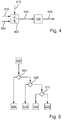
- FIG. 4 1 shows a schematic block diagram for operating the illumination device 101.
- the light source unit 109 is operated in dependence on the wirelessly received control signal 330 and emits a light emission distribution 400. If the wirelessly received control signal 330 falls away, that is, if it is no longer available, then a safety mode 410 is changed.
- the safety mode 410 the light source unit 109 is operated in response to the wirelessly received sensor signal 340, which is a Change the emission light distribution 400 can cause.
- the sensor signal 340 is selected in a block 402 in order to determine an operating signal 404 and make it available to the light source unit 109.
- FIG. 5 shows a schematic flow diagram for the operation of the lighting device 101.
- the lighting device 101 is turned on.
- a functional test takes place in which functional tests of the light module 105 or the control unit 108 or the wireless interface 107 are performed. If all functional tests end with a positive result, then the light module 105 or the illumination device 101 is started in a normal mode 506. In normal operation 506, the light source unit 109 is operated in response to the wirelessly received control signal 330.
- step 508 it is checked in a step 508 whether the control signal 330 of the control unit 108 is present. If this is the case, an error signal is sent to the central control unit 202 via the communication channel 310 as a function of the determination of the malfunction. In response to sending the error signal, another control signal 330 is received for a first security operation 510. In the security mode 510, the light source unit 109 is operated in response to the wirelessly received another control signal.
- step 512 checks whether in the control unit 108, the sensor signal 340 is present. If this is the case, the second safety mode 410 is changed and the light source unit 109 is operated in dependence on the wirelessly received sensor signal 340.
- step 512 if it is determined in step 512 that there is no sensor signal 340, then a change is made to a third safety mode 520, in which an operating signal is independently determined by the control unit 108.
- the light source unit 109 is operated in the third safety mode 520 as a function of the independently determined operating signal.
- FIG. 6 shows a schematic sequence diagram for the normal operation of the lighting device 101.
- the wireless interface 107, the control unit 108, and the light source unit 109 are disposed on the common light module 105.
- the control unit 108, and the light source unit 109 are disposed on the common light module 105.
- other designs are conceivable, for example according to the FIG. 2 ,
- the central control unit 202 determines the control signal 330 which is transmitted via the communication channel 310 to the wireless interface 107.
- the wireless interface 107 receives the control signal 330 in a step 604 and transmits the control signal 330 or a variable derived therefrom to a control unit 108.
- the control unit 108 determines in a step 606 an operating signal 608 which is transmitted to the light source unit 109.
- the light source unit 109 is operated to generate light.
- FIG. 7 2 shows a schematic sequence diagram for the first safety operation 510.
- the control unit 108 detects a malfunction of the illumination device 101 during a functional test and determines the error signal 704.
- the error signal 704 is transmitted to the wireless interface 107.
- a wireless transmission of the error signal 704 is prepared.
- the error signal 704 is sent wirelessly.
- the central control unit 202 determines another control signal 730 which is wirelessly transmitted from the central control unit 202.
- the wireless interface 107 wirelessly receives the further control signal 730 in a step 710 and provides the further control signal 730 to the control unit 108.
- the control unit 108 determines an operating signal 740.
- the light source unit 109 is operated in a step 714 as a function of the determined operating signal 740.
- FIG. 8 2 shows a schematic sequence diagram for the second safety operation 410.
- the second safety operation 410 occurs, for example, in that the central control unit 202 determines the control signal 330 in step 602, which however is not received via the wireless interface 107 due to a malfunction of the communication channel 310 , The wireless interface 107 determines in a step 802 that the control signal 330 is missing in the form of a signal 804. In a step 806, the control unit 108 determines the second safety mode 410 in response to the signal 804.
- the control unit 108 via the wireless interface 107, the sensor unit 204 to send the sensor signal 340 activate.
- the sensor unit 204 constantly sends the sensor signal 340.
- the central control unit 202 activates the sensor unit 204 for wireless transmission of the sensor signal 340 in the event of a loss of the communication channel 310 via a further wired or wireless communication channel.
- the sensor unit 204 determines in a step 810 the sensor signal 340 which is received wirelessly in a step 812 from the wireless interface 107.
- the sensor signal 340 is transmitted from the wireless interface 107 to the control unit 108.
- the control unit 108 determines in a step 814 an operation signal 820 for the light source unit 109 in response to the sensor signal 340.
- the light source unit 109 is operated in response to the operation signal 820 in a step 816.
- FIG. 9 3 shows a schematic sequence diagram of the third safety operation 520.
- the prerequisite for the third safety operation 520 is that a wireless reception of the control signal as 330 and a reception of the sensor signal 340 do not occur. This can be caused for example by a disturbance of the two communication channels 310 and 320.
- the wireless interface 107 detects a failure to receive the control signal 330 and determines a signal 904.
- the controller 108 determines the absence of the control signal as 330.
- the wireless interface 107 detects the absence of the sensor signal 340 and determines a signal 910.
- the controller sets 108, the absence of the sensor signal 340 fixed.
- control unit 108 independently determines in a step 914 an operating signal 920 for operating the light source unit 109.
- the light source unit 109 is operated in dependence on the operating signal 920.
- the 510, 410 and 520 procedures and tiered security operations make it possible to ensure compliance with legal security requirements, including wireless interfaces and wireless communication channels.
- legal security requirements including wireless interfaces and wireless communication channels.
- the presented method will be described within the scope of the dipped-beam light function.
- the low beam light is adjusted by the light source unit 109 in response to the wirelessly received control signal 330.
- the central control unit 202 accesses, for example, a sensor signal from the sensor unit 204 back.
- the setting of the cut-off line can be done electronically by switching on or off individual light sources or mechanically by means of an electric motor.
- the control unit 108 or the control unit 128 determines a malfunction affecting the light module 105, the first safety operation is changed as far as the communication channel 310 is functional. Compared to the normal operation 506, the further control signal 730 is now determined in such a way as to ensure dazzling of oncoming traffic. The light-dark boundary is therefore in the first safety operation compared to the cut-off line in normal operation lowered.
- the central control unit 202 does not receive any of the control signals 330, 730.
- the sensor unit 204 represents an axle sensor, which transmits a deflection in the sense of the sensor signal 340 wirelessly to the illumination device 101.
- the control unit 108 determines the operating signal 820 so as to set the bright-dark limit of the emitted low-beam light distribution independently of the central control unit 202.
- the third safety operation 520 is activated and the light source unit 109 is operated as a function of the operating signal 920.
- the operating signal 920 causes the cut-off line to be faded down, i. lowered as much as possible.
- the luminous intensity is increased or reduced in at least a portion of the radiated light distribution. This occurs as a function of a supplied control signal 330 and in the context of the safety mode 410 as a function of a sensor signal 340.
Landscapes
- Engineering & Computer Science (AREA)
- Mechanical Engineering (AREA)
- Computer Networks & Wireless Communication (AREA)
- Lighting Device Outwards From Vehicle And Optical Signal (AREA)
Abstract
Es wird ein Verfahren zum Betreiben einer Beleuchtungseinrichtung eines Kraftfahrzeugs mit einer Lichtquelleneinheit (109) zur Erzeugung einer Abstrahllichtverteilung (400) vorgeschlagen. Die Lichtquelleneinheit (109) wird in einem Normalbetrieb in Abhängigkeit von einem drahtlos empfangenen Kontrollsignal (330) betrieben. Ein Wegfall des drahtlos empfangenen Kontrollsignals (330) wird ermittelt. Die Lichtquelleneinheit (109) wird in einem Sicherheitsbetrieb (410) in Abhängigkeit von einem drahtlos empfangenen Sensorsignal (340) betrieben.A method is proposed for operating a lighting device of a motor vehicle with a light source unit (109) for generating a light emission distribution (400). The light source unit (109) is operated in a normal operation in response to a wirelessly received control signal (330). An omission of the wirelessly received control signal (330) is determined. The light source unit (109) is operated in a safety mode (410) in response to a wirelessly received sensor signal (340).
Description
Die Erfindung betrifft ein Verfahren zum Betreiben einer Beleuchtungseinrichtung nach dem Oberbegriff des Anspruchs 1 sowie eine Beleuchtungseinrichtung nach einem nebengeordneten Anspruch.The invention relates to a method for operating a lighting device according to the preamble of claim 1 and to a lighting device according to an independent claim.
Es ist bekannt, dass Kraftfahrzeugscheinwerfer zunehmend komplexere Lichtfunktionen realisieren. Beispielsweise können mittels adaptiven Fernlichts einzelne Ausschnitte des Sichtfeldes des Fahrers durch eine bereichsweise Erhöhung der Lichtstärke hervorgehoben werden. Andererseits kann zur Vermeidung der Blendung des Gegenverkehrs die Lichtstärke in anderen Ausschnitten reduziert werden.It is known that motor vehicle headlamps realize increasingly complex lighting functions. For example, by means of adaptive high beam individual sections of the field of view of the driver can be highlighted by a regional increase in the intensity of light. On the other hand, in order to avoid dazzling oncoming traffic, the light intensity in other sections can be reduced.
Zur Realisierung dieser Lichtfunktionen ist es nötig, dass der Beleuchtungseinrichtung ein entsprechendes Kontrollsignal zugeführt wird. Mit der Komplexität der Lichtfunktion skaliert ebenso die Komplexität des Kontrollsignals, was sich unmittelbar auf die Komplexität des der Beleuchtungseinrichtung zugeführten Kabelbaums auswirkt. Ein zugehöriges Steckverbindersystem zwischen Kabelbaum und Beleuchtungseinrichtung muss die erhöhte Anzahl von Signalleitungen abbilden.To realize these lighting functions, it is necessary that the lighting device is supplied with a corresponding control signal. With the complexity of the light function scales the complexity of the same Control signal, which directly affects the complexity of the lighting device supplied harness. An associated connector system between harness and lighting device must map the increased number of signal lines.
Gleichzeitig bestehen gesetzliche Anforderungen an die Abstrahllichtverteilung, die auch bei einem Ausfall von Teilsystemen der Beleuchtungseinrichtung oder des Kraftfahrzeugs erfüllt werden müssen.At the same time there are legal requirements for the Abstrahllichtverteilung, which must be met even in case of failure of subsystems of the lighting device or the motor vehicle.
Mithin besteht die Aufgabe der Erfindung darin, zum einen den im Kraftfahrzeug vorhandenen Kabelbaum zu reduzieren und gleichzeitig die funktionale Sicherheit im Rahmen der gesetzlichen Anforderungen zu erfüllen.Thus, the object of the invention is to reduce the existing wiring harness in the motor vehicle while fulfilling the functional safety within the legal requirements.
Die der Erfindung zugrunde liegende Aufgabe wird durch ein Verfahren zum Betreiben einer Beleuchtungseinrichtung nach dem Anspruch 1 sowie durch eine Beleuchtungseinrichtung nach einem nebengeordneten Anspruch gelöst.The object underlying the invention is achieved by a method for operating a lighting device according to claim 1 and by a lighting device according to an independent claim.
Eine Lichtquelleneinheit wird in einem Normalbetrieb in Abhängigkeit von einem drahtlos empfangenen Kontrollsignal betrieben. Ein Wegfall des drahtlos empfangenen Kontrollsignals wird ermittelt. Die Lichtquelleneinheit wird in einem Sicherheitsbetrieb in Abhängigkeit von einem drahtlos empfangenen Sensorsignal betrieben. Die zur Übermittlung des Kontrollsignals und des Sensorsignals sonst nötigen Signalleitungen können damit entfallen, was sich positiv auf den Kabelbaum und damit positiv auf das Gesamtgewicht des Kraftfahrzeugs auswirkt. Des Weiteren kann durch den Sicherheitsbetrieb die Verfügbarkeit der Lichtfunktion erhöht werden.A light source unit is operated in normal operation in response to a wirelessly received control signal. An omission of the wirelessly received control signal is determined. The light source unit is operated in a safety mode in response to a wirelessly received sensor signal. The signal lines otherwise necessary for the transmission of the control signal and the sensor signal can thus be omitted, which has a positive effect on the wiring harness and thus has a positive effect on the overall weight of the motor vehicle. Furthermore, the availability of the light function can be increased by the safety operation.
In einer vorteilhaften Ausführungsform wird im Normalbetrieb eine Fehlfunktion der Beleuchtungseinrichtung ermittelt. Ein Fehlersignal wird in Abhängigkeit von der Ermittlung der Fehlfunktion drahtlos versendet. In Reaktion auf das Versenden des Fehlersignals wird ein weiteres Kontrollsignal für einen weiteren Sicherheitsbetrieb der Lichtquelleneinheit drahtlos empfangen. Die Lichtquelleneinheit wird in Abhängigkeit von dem drahtlos empfangenen weiteren Kontrollsignal in dem weiteren Sicherheitsbetrieb betrieben.In an advantageous embodiment is in Normal operation determines a malfunction of the lighting device. An error signal is sent wireless depending on the detection of the malfunction. In response to sending the error signal, another control signal is received wirelessly for another security operation of the light source unit. The light source unit is operated in dependence on the wirelessly received further control signal in the further safety operation.
Damit wird ermöglicht, dass der Kommunikationskanal zwischen einer zentralen Steuereinheit und der Beleuchtungseinheit auch im Fehlerfall dazu genutzt wird, um weiterhin in Abhängigkeit von der zentralen Steuereinheit die Beleuchtungseinrichtung zu betreiben. Der Betrieb der Lichtquelleneinheit lediglich in Abhängigkeit von dem Sensorsignal kann somit vorerst vermieden werden.This makes it possible that the communication channel between a central control unit and the lighting unit is also used in the event of a fault to continue to operate in dependence on the central control unit, the lighting device. The operation of the light source unit only as a function of the sensor signal can thus be avoided for the time being.
In einer weiteren vorteilhaften Ausführungsform wird ein Wegfall des Sensorsignals ermittelt. Ein Betriebssignal wird eigenständig für einen zusätzlichen Sicherheitsbetrieb der Lichtquelleneinheit ermittelt. Die Lichtquelleneinheit wird in dem zusätzlichen Sicherheitsbetrieb in Abhängigkeit von dem eigenständig ermittelten Betriebssignal betrieben. Damit wird eine weitere Rückfallebene geschaffen, um bei einem Wegfall des Sensorsignals noch die gesetzlichen Anforderungen an eine Abstrahllichtverteilung zu erfüllen.In a further advantageous embodiment, an omission of the sensor signal is determined. An operating signal is determined independently for an additional safety operation of the light source unit. The light source unit is operated in the additional safety mode as a function of the independently determined operating signal. Thus, a further fallback level is created in order to still meet the legal requirements for a Abstrahllichtverteilung at a loss of the sensor signal.
Weitere Ausführungsformen und Merkmale sind in der nachfolgenden Beschreibung und in den Figuren der Zeichnung dargestellt. Für äquivalente Merkmale werden auch bei unterschiedlichen Ausführungsformen die gleichen Bezugszeichen verwendet. In der Zeichnung zeigen:
- Figuren 1 und 2
- jeweils eine schematisch dargestellte Beleuchtungseinrichtung;
- Figur 3
- ein schematisch dargestelltes Kraftfahrzeug;
- Figur 4
- ein schematisches Blockdiagramm zum Betreiben der Beleuchtungseinrichtung;
Figur 5- ein schematisches Ablaufdiagramm zum Betrieb der Beleuchtungseinrichtung; und
- Figuren 6, 7, 8 und 9
- jeweils schematisch dargestellte Sequenzdiagramme.
- Figures 1 and 2
- in each case a schematically illustrated illumination device;
- FIG. 3
- a schematically illustrated motor vehicle;
- FIG. 4
- a schematic block diagram for operating the illumination device;
- FIG. 5
- a schematic flow diagram for the operation of the illumination device; and
- FIGS. 6, 7, 8 and 9
- each schematically illustrated sequence diagrams.
Innerhalb des Scheinwerfergehäuses 102 befinden sich Lichtmodule 105 und 106. Das Lichtmodul 105 umfasst eine Drahtlosschnittstelle 107 zum drahtlosen Empfang von Signalen. Drahtlos empfangenen Signale werden einer Steuereinheit 108 zugeführt, welche in Abhängigkeit von den drahtlos empfangenen Signalen eine Lichtquelleneinheit 109 betreibt. Ebenso ist es möglich, dass die Steuereinheit 108 mittels der Drahtlosschnittstelle 107 Signale drahtlos versendet. Das Lichtmodul 106 ist analog zum Lichtmodul 105 aufgebaut und umfasst eine Drahtlosschnittstelle 117, eine Steuereinheit 118 sowie eine Leuchteinheit 119. Die Lichtmodule 105 und 106 können dieselbe oder unterschiedliche Lichtfunktionen realisieren. Beispielsweise wird mittels des ersten Lichtmoduls 105 eine Abblendlichtverteilung erzeugt und mittels des Lichtmoduls 106 eine Fernlichtverteilung.Within the
Versorgungsleitungen 110 für die Lichtmodule 105,106 sind an einen Steckverbinder 112 geführt. Der Steckverbinder 112 stellt beispielhaft lediglich 2 Kontaktstellen zur Verfügung soweit alle Signale über die Drahtlosschnittstellen 107 und 117 mit dem Kraftfahrzeug bzw. einer zugeordneten Steuereinheit bzw. einer zugeordneten zentralen Sensoreinheit ausgetauscht werden.
Die Steuereinheit 108 umfasst ein digitales Rechengerät 120, beispielsweise einen Mikrocontroller, und ein Speichermedium 122. Die hier beschriebenen Verfahren können als Computerprogramm für das digitale Rechengerät 120 ausgebildet sein, um auf dem Rechengerät 120 ausgeführt zu werden. Das Computerprogramm ist auf dem Speichermedium 122 abgespeichert.The
Alternativ zu der Ausbildung als Mikrocontroller mit zugeordneten Speichermedium 122 kann die Steuereinheit 108 auch als Treiberstufe, d.h. als elektronische Schaltung, ausgebildet sein. Hierbei kann die Drahtlosschnittstelle 107 derart ausgebildet sein, als dass die hier dargestellten Verfahren durchführbar sind. In diesem Fall übernimmt die Drahtlosschnittstelle 107 teilweise die Funktionalität der beschriebenen Steuereinheit 108.As an alternative to the configuration as a microcontroller with associated
Die zentrale Steuereinheit 202 umfasst eine Recheneinheit 206, welche eine Drahtlosschnittstelle 208 betreibt. Über die Drahtlosschnittstelle 208 und die Drahtlosschnittstelle 107 kann ein drahtloser Kommunikationskanal 310 aufgebaut werden, um Signale zwischen der Steuereinheit 202 und der Steuereinheit 108 drahtlos auszutauschen. Über den Kommunikationskanal 310 wird ein Kontrollsignal 330 von der zentralen Steuereinheit 202 an die Steuereinheit 108 übertragen.The
Die Sensoreinheit 204 umfasst ein Sensorelement 216, welches eine Drahtlosschnittstelle 218 anspricht. Über die Drahtlosschnittstelle 218 kann ein drahtloser Kommunikationskanal 320 aufgebaut werden, um Signale zwischen der Sensoreinheit 204 und der Steuereinheit 108 auszutauschen. Über den Kommunikationskanal 320 wird ein Sensorsignal 340 von der Sensoreinheit 204 an die Steuereinheit 108 übertragen.The
Dass in
Für die Drahtlosschnittstellen 107, 208 und 218 können verschiedene Technologien zum Einsatz kommen. Beispielsweise können die Drahtlosschnittstellen 107, 28 und 218 gemäß IEEE 802.11 (Wireless Local Area Network) ausgebildet sein. Alternativ können die Drahtlosschnittstellen 107, 108 und 218 auch im Rahmen einer Nahfeldkommunikation durch Kapazität und/oder induktive Kopplung Signale untereinander austauschen.For the wireless interfaces 107, 208 and 218, various technologies may be used. For example, the wireless interfaces 107, 28 and 218 may be configured in accordance with IEEE 802.11 (Wireless Local Area Network). Alternatively, the wireless interfaces 107, 108 and 218 can also exchange signals with one another in the context of a near field communication by means of capacitance and / or inductive coupling.
Darüber hinaus ist es auch möglich, dass anstatt einer einzigen Drahtlosschnittstelle 107 auf Seiten der Beleuchtungsrichtung 101 mehrere drahtlos Schnittstellen vorhanden sind, welche darüber hinaus auch unterschiedliche, oben genannte Kommunikationstechnologien verwenden können, um die Kommunikationskanäle 310 und 320 herzustellen.Moreover, it is also possible that, instead of a
Wird zumindest ein Funktionstest mit einem negativen Ergebnis abgeschlossen, so wird in einem Schritt 508 überprüft, ob das Kontrollsignal 330 der Steuereinheit 108 vorliegt. Ist dies der Fall, so wird über den Kommunikationskanal 310 in Abhängigkeit von der Ermittlung der Fehlfunktion ein Fehlersignal an die zentrale Steuereinheit 202 versendet. In Reaktion auf das Versenden des Fehlersignals wird ein weiteres Kontrollsignal 330 für einen ersten Sicherheitsbetrieb 510 empfangen. In dem Sicherheitsbetrieb 510 wird die Lichtquelleneinheit 109 in Abhängigkeit von dem drahtlos empfangenen weiteren Kontrollsignal betrieben.If at least one functional test is concluded with a negative result, it is checked in a
Wird in Schritt 508 jedoch festgestellt, dass kein Kontrollsignal 330 ausgehend von der zentralen Steuereinheit 202 vorliegt, so wird in einem Schritt 512 überprüft, ob in der Steuereinheit 108 das Sensorsignal 340 vorliegt. Ist dies der Fall, wird in den zweiten Sicherheitsbetrieb 410 gewechselt und die Lichtquelleneinheit 109 wird in Abhängigkeit von dem drahtlos empfangenen Sensorsignal 340 betrieben.However, if it is determined in
Wird in dem Schritt 512 jedoch festgestellt, dass kein Sensorsignal 340 vorliegt, so wird in einen dritten Sicherheitsbetrieb 520 gewechselt, in welchem ein Betriebssignal eigenständig von der Steuereinheit 108 ermittelt wird. Die Lichtquelleneinheit 109 wird in dem dritten Sicherheitsbetrieb 520 in Abhängigkeit von dem eigenständig ermittelten Betriebssignal betrieben.However, if it is determined in
In einem Schritt 602 ermittelt die zentrale Steuereinheit 202 das Kontrollsignal 330 welches über den Kommunikationskanal 310 an die Drahtlosschnittstelle 107 übermittelt wird. Die Drahtlosschnittstelle 107 empfängt in einem Schritt 604 das Kontrollsignal 330 und übermittelt das Kontrollsignal 330 oder eine daraus abgeleitete Größe eine Steuereinheit 108. Die Steuereinheit 108 ermittelt in einem Schritt 606 ein Betriebssignal 608, welches an die Lichtquelleneinheit 109 übermittelt wird. In Abhängigkeit von dem Betriebssignal 608 wird in einem Schritt 610 die Lichtquelleneinheit 109 zu einer Lichterzeugung betrieben.In a
In dem Sicherheitsbetrieb 410 kann die Steuereinheit 108 über die Drahtlosschnittstelle 107 die Sensoreinheit 204 zum Senden des Sensorsignals 340 aktivieren. In einer anderen Ausführungsform sendet die Sensoreinheit 204 ständig das Sensorsignal 340. Ebenso ist es möglich dass die zentrale Steuereinheit 202 bei einem Wegfall des Kommunikationskanals 310 über einen weiteren drahtgebundenen oder drahtlosen Kommunikationskanal die Sensoreinheit 204 zum drahtlosen Aussenden des Sensorsignals 340 aktiviert.In the
Die Sensoreinheit 204 ermittelt in einem Schritt 810 das Sensorsignal 340, welches drahtlos in einem Schritt 812 von der Drahtlosschnittstelle 107 empfangen wird. Das Sensorsignal 340 wird von der Drahtlosschnittstelle 107 der Steuereinheit 108 übermittelt. Die Steuereinheit 108 ermittelt in einem Schritt 814 ein Betriebssignal 820 für die Lichtquelleneinheit 109 in Abhängigkeit von den Sensorsignal 340. Die Lichtquelleneinheit 109 wird in Abhängigkeit von den Betriebssignal 820 in einem Schritt 816 betrieben.The
Werden also weder das Kontrollsignal 330 noch das Sensorsignal 340 empfangen, so ermittelt die Steuereinheit 108 selbstständig in einem Schritt 914 ein Betriebssignal 920 zum Betrieb der Lichtquelleneinheit 109. In einem Schritt 916 wird die Lichtquelleneinheit 109 in Abhängigkeit von den Betriebssignal 920 betrieben.Thus, if neither the
Mit den vorgestellten Verfahren und abgestuften Sicherheitsbetrieben 510, 410 und 520 ist es möglich die gesetzlichen Sicherheitsanforderungen auch unter Zuhilfenahme von Drahtlosschnittstellen und drahtlosen Kommunikationskanälen sicherzustellen. Lediglich beispielhaft wird das vorgestellte Verfahren im Rahmen der Lichtfunktion Abblendlicht beschrieben.The 510, 410 and 520 procedures and tiered security operations make it possible to ensure compliance with legal security requirements, including wireless interfaces and wireless communication channels. By way of example only, the presented method will be described within the scope of the dipped-beam light function.
In dem Normalbetrieb wird das Abblendlicht mittels der Lichtquelleneinheit 109 in Abhängigkeit von den drahtlos empfangenen Kontrollsignal 330 eingestellt. Hierzu greift die zentrale Steuereinheit 202 beispielsweise auf ein Sensorsignal ausgehend von der Sensoreinheit 204 zurück. Die Einstellung der Hell-Dunkel-Grenze kann elektronisch durch Ein- bzw. Ausschalten einzelner Lichtquellen oder mechanisch mittels eines Elektromotors erfolgen.In the normal operation, the low beam light is adjusted by the
Stellt die Steuereinheit 108 bzw. die Steuereinheit 128 eine Fehlfunktion fest, welche das Lichtmodul 105 betrifft, so wird in den ersten Sicherheitsbetrieb gewechselt, soweit der Kommunikationskanal 310 funktionsfähig ist. Gegenüber dem Normalbetrieb 506 wird nunmehr das weitere Kontrollsignal 730 dahingehend ermittelt, als dass eine Blendung des Gegenverkehrs gewährleistet bleibt. Die Hell-Dunkel-Grenze wird somit im ersten Sicherheitsbetrieb gegenüber der Hell-Dunkel-Grenze im Normalbetrieb abgesenkt.If the
In dem zweiten Sicherheitsbetrieb 410 wird festgestellt, dass von der zentralen Steuereinheit 202 keines der Kontrollsignale 330, 730 empfangen wird. In diesem Fall stellt die Sensoreinheit 204 einen Achssensor dar, welcher eine Einfederung im Sinne des Sensorsignals 340 drahtlos an die Beleuchtungseinrichtung 101 übermittelt. In Abhängigkeit von der Einfederung ermittelt die Steuereinheit 108 das Betriebssignal 820, um somit unabhängig von der zentralen Steuereinheit 202 die Hell-Dunkel-Grenze der abgestrahlten Abblendlichtverteilung einzustellen.In the
Fällt nun auch das Sensorsignal 340 weg, so wird der dritte Sicherheitsbetrieb 520 aktiviert und die Lichtquelleneinheit 109 wird in Abhängigkeit von dem Betriebssignal 920 betrieben. Das Betriebssignal 920 sorgt dafür, dass die Hell-Dunkel-Grenze nach unten geblendet, d.h. so weit wie möglich abgesenkt wird.If the
Selbstverständlich sind neben der Abblendlichtfunktion weitere Beispiele denkbar, um die jeweiligen Sicherheitsbetrieb durchzuführen. Beispielhaft sei auf blendfreies bzw. adaptives Fernlicht verwiesen. Hierbei wird in zumindest einem Teilbereich der abgestrahlten Lichtverteilung die Lichtstärke erhöht bzw. reduziert. Dies geschieht in Abhängigkeit von einem zugeführten Kontrollsignal 330 und im Rahmen des Sicherheitsbetriebs 410 in Abhängigkeit von einem Sensorsignal 340.Of course, in addition to the low beam function further examples are conceivable to perform the respective safety operation. For example, reference is made to glare-free or adaptive high beam. In this case, the luminous intensity is increased or reduced in at least a portion of the radiated light distribution. This occurs as a function of a supplied
Claims (9)
Applications Claiming Priority (1)
| Application Number | Priority Date | Filing Date | Title |
|---|---|---|---|
| DE102016122341.7A DE102016122341A1 (en) | 2016-11-21 | 2016-11-21 | Method for operating a lighting device and lighting device |
Publications (2)
| Publication Number | Publication Date |
|---|---|
| EP3324710A1 true EP3324710A1 (en) | 2018-05-23 |
| EP3324710B1 EP3324710B1 (en) | 2023-12-27 |
Family
ID=60327136
Family Applications (1)
| Application Number | Title | Priority Date | Filing Date |
|---|---|---|---|
| EP17201587.7A Active EP3324710B1 (en) | 2016-11-21 | 2017-11-14 | Method for operating a lighting device and lighting device |
Country Status (2)
| Country | Link |
|---|---|
| EP (1) | EP3324710B1 (en) |
| DE (1) | DE102016122341A1 (en) |
Cited By (1)
| Publication number | Priority date | Publication date | Assignee | Title |
|---|---|---|---|---|
| WO2020049115A1 (en) | 2018-09-07 | 2020-03-12 | Daimler Ag | Vehicle lamp |
Citations (3)
| Publication number | Priority date | Publication date | Assignee | Title |
|---|---|---|---|---|
| US20160023588A1 (en) * | 2009-04-04 | 2016-01-28 | Classic Safety Products, LLC | Removable Signaling Apparatus, System, and Method |
| DE102014221666A1 (en) * | 2014-10-24 | 2016-04-28 | Osram Gmbh | lighting device |
| KR101621876B1 (en) * | 2014-12-16 | 2016-05-17 | 현대자동차주식회사 | Method for controlling headlight using wearable device and vehicle for carrying out the same |
-
2016
- 2016-11-21 DE DE102016122341.7A patent/DE102016122341A1/en not_active Withdrawn
-
2017
- 2017-11-14 EP EP17201587.7A patent/EP3324710B1/en active Active
Patent Citations (3)
| Publication number | Priority date | Publication date | Assignee | Title |
|---|---|---|---|---|
| US20160023588A1 (en) * | 2009-04-04 | 2016-01-28 | Classic Safety Products, LLC | Removable Signaling Apparatus, System, and Method |
| DE102014221666A1 (en) * | 2014-10-24 | 2016-04-28 | Osram Gmbh | lighting device |
| KR101621876B1 (en) * | 2014-12-16 | 2016-05-17 | 현대자동차주식회사 | Method for controlling headlight using wearable device and vehicle for carrying out the same |
Cited By (2)
| Publication number | Priority date | Publication date | Assignee | Title |
|---|---|---|---|---|
| WO2020049115A1 (en) | 2018-09-07 | 2020-03-12 | Daimler Ag | Vehicle lamp |
| DE102018007092B4 (en) | 2018-09-07 | 2024-05-02 | Daimler Truck AG | Vehicle light |
Also Published As
| Publication number | Publication date |
|---|---|
| DE102016122341A1 (en) | 2018-05-24 |
| EP3324710B1 (en) | 2023-12-27 |
Similar Documents
| Publication | Publication Date | Title |
|---|---|---|
| EP2548768B1 (en) | Headlamp for a motor vehicle | |
| EP1819567B2 (en) | Electromechanical parking brake system and electronic system for the driving thereof | |
| DE60200395T2 (en) | Lighting or signaling headlight and method with at least one headlight | |
| EP2750930B1 (en) | Method for signaling a braking process on a trailer vehicle, control device, and trailer vehicle | |
| DE102016124570A1 (en) | METHOD AND DEVICE FOR WIRELESS COMMUNICATION AND POWER TRANSMISSION FOR AN EXTERNAL PORCH LAMP | |
| WO2006053651A1 (en) | Goods-carrying vehicle with lighting units that can be controlled by means of plc (power line communication) | |
| WO2011161156A1 (en) | Industrial truck comprising a work luminaire and method for activating and deactivating | |
| DE102018220605B4 (en) | Motor vehicle network and method for operating a motor vehicle network | |
| EP3324710A1 (en) | Method for operating a lighting device and lighting device | |
| EP2890591A1 (en) | Method for operating a light system and light system | |
| EP3106346A1 (en) | Autonomous actuator for adjusting a light distribution of a lighting device of a motor vehicle | |
| WO2016156366A1 (en) | Circuit arrangement for operating a plurality of lighting devices of a motor vehicle | |
| DE102016203966A1 (en) | Control unit and method for controlling at least one actuator of a vehicle | |
| DE102017101803B4 (en) | Device for at least partially interrupting a communication line of a vehicle | |
| DE102017217590A1 (en) | In-vehicle lighting system | |
| WO2017009023A1 (en) | Method for operating a first and a second light-emitting unit of a motor vehicle, and circuit arrangement | |
| EP3162634A1 (en) | Control device for controlling or regulating at least one lighting device and motor vehicle with such a control device | |
| DE102012222013B4 (en) | Combined control device and method for a light of a vehicle | |
| EP3571106B1 (en) | System for illuminating a rail vehicle and rail vehicle | |
| DE102014002544A1 (en) | System with an operating device set up for operating a vehicle-side device and method for controlling the operating device | |
| DE202010016339U1 (en) | circuitry | |
| AT506439B1 (en) | REDUNDANT BUS SYSTEM | |
| DE102017101846A1 (en) | Device, system, method for configuring the device, method for operating the system, computer program product and computer-readable medium for the electrical control of at least one real electrical consumer of a motor vehicle | |
| EP3484250B1 (en) | Method, task light and work machine for configuring lights | |
| DE102014005013B4 (en) | Method for operating a control device in a motor vehicle and motor vehicle |
Legal Events
| Date | Code | Title | Description |
|---|---|---|---|
| PUAI | Public reference made under article 153(3) epc to a published international application that has entered the european phase |
Free format text: ORIGINAL CODE: 0009012 |
|
| STAA | Information on the status of an ep patent application or granted ep patent |
Free format text: STATUS: THE APPLICATION HAS BEEN PUBLISHED |
|
| AK | Designated contracting states |
Kind code of ref document: A1 Designated state(s): AL AT BE BG CH CY CZ DE DK EE ES FI FR GB GR HR HU IE IS IT LI LT LU LV MC MK MT NL NO PL PT RO RS SE SI SK SM TR |
|
| AX | Request for extension of the european patent |
Extension state: BA ME |
|
| STAA | Information on the status of an ep patent application or granted ep patent |
Free format text: STATUS: REQUEST FOR EXAMINATION WAS MADE |
|
| 17P | Request for examination filed |
Effective date: 20181121 |
|
| RBV | Designated contracting states (corrected) |
Designated state(s): AL AT BE BG CH CY CZ DE DK EE ES FI FR GB GR HR HU IE IS IT LI LT LU LV MC MK MT NL NO PL PT RO RS SE SI SK SM TR |
|
| STAA | Information on the status of an ep patent application or granted ep patent |
Free format text: STATUS: REQUEST FOR EXAMINATION WAS MADE |
|
| STAA | Information on the status of an ep patent application or granted ep patent |
Free format text: STATUS: EXAMINATION IS IN PROGRESS |
|
| 17Q | First examination report despatched |
Effective date: 20210512 |
|
| STAA | Information on the status of an ep patent application or granted ep patent |
Free format text: STATUS: EXAMINATION IS IN PROGRESS |
|
| REG | Reference to a national code |
Ref document number: 502017015706 Country of ref document: DE Ref country code: DE Ref legal event code: R079 Free format text: PREVIOUS MAIN CLASS: H05B0037020000 Ipc: B60Q0001000000 |
|
| GRAP | Despatch of communication of intention to grant a patent |
Free format text: ORIGINAL CODE: EPIDOSNIGR1 |
|
| STAA | Information on the status of an ep patent application or granted ep patent |
Free format text: STATUS: GRANT OF PATENT IS INTENDED |
|
| RIC1 | Information provided on ipc code assigned before grant |
Ipc: B60Q 1/04 20060101ALI20230512BHEP Ipc: B60Q 11/00 20060101ALI20230512BHEP Ipc: H05B 47/19 20200101ALI20230512BHEP Ipc: H05B 47/17 20200101ALI20230512BHEP Ipc: B60Q 1/00 20060101AFI20230512BHEP |
|
| INTG | Intention to grant announced |
Effective date: 20230615 |
|
| GRAS | Grant fee paid |
Free format text: ORIGINAL CODE: EPIDOSNIGR3 |
|
| GRAA | (expected) grant |
Free format text: ORIGINAL CODE: 0009210 |
|
| STAA | Information on the status of an ep patent application or granted ep patent |
Free format text: STATUS: THE PATENT HAS BEEN GRANTED |
|
| RAP3 | Party data changed (applicant data changed or rights of an application transferred) |
Owner name: MARELLI AUTOMOTIVE LIGHTING REUTLINGEN (GERMANY) GMBH |
|
| AK | Designated contracting states |
Kind code of ref document: B1 Designated state(s): AL AT BE BG CH CY CZ DE DK EE ES FI FR GB GR HR HU IE IS IT LI LT LU LV MC MK MT NL NO PL PT RO RS SE SI SK SM TR |
|
| REG | Reference to a national code |
Ref country code: GB Ref legal event code: FG4D Free format text: NOT ENGLISH |
|
| REG | Reference to a national code |
Ref country code: CH Ref legal event code: EP |
|
| REG | Reference to a national code |
Ref country code: DE Ref legal event code: R096 Ref document number: 502017015706 Country of ref document: DE |
|
| REG | Reference to a national code |
Ref country code: IE Ref legal event code: FG4D Free format text: LANGUAGE OF EP DOCUMENT: GERMAN |
|
| PG25 | Lapsed in a contracting state [announced via postgrant information from national office to epo] |
Ref country code: GR Free format text: LAPSE BECAUSE OF FAILURE TO SUBMIT A TRANSLATION OF THE DESCRIPTION OR TO PAY THE FEE WITHIN THE PRESCRIBED TIME-LIMIT Effective date: 20240328 |
|
| REG | Reference to a national code |
Ref country code: LT Ref legal event code: MG9D |
|
| PG25 | Lapsed in a contracting state [announced via postgrant information from national office to epo] |
Ref country code: LT Free format text: LAPSE BECAUSE OF FAILURE TO SUBMIT A TRANSLATION OF THE DESCRIPTION OR TO PAY THE FEE WITHIN THE PRESCRIBED TIME-LIMIT Effective date: 20231227 |
|
| PG25 | Lapsed in a contracting state [announced via postgrant information from national office to epo] |
Ref country code: ES Free format text: LAPSE BECAUSE OF FAILURE TO SUBMIT A TRANSLATION OF THE DESCRIPTION OR TO PAY THE FEE WITHIN THE PRESCRIBED TIME-LIMIT Effective date: 20231227 |
|
| PG25 | Lapsed in a contracting state [announced via postgrant information from national office to epo] |
Ref country code: LT Free format text: LAPSE BECAUSE OF FAILURE TO SUBMIT A TRANSLATION OF THE DESCRIPTION OR TO PAY THE FEE WITHIN THE PRESCRIBED TIME-LIMIT Effective date: 20231227 Ref country code: GR Free format text: LAPSE BECAUSE OF FAILURE TO SUBMIT A TRANSLATION OF THE DESCRIPTION OR TO PAY THE FEE WITHIN THE PRESCRIBED TIME-LIMIT Effective date: 20240328 Ref country code: FI Free format text: LAPSE BECAUSE OF FAILURE TO SUBMIT A TRANSLATION OF THE DESCRIPTION OR TO PAY THE FEE WITHIN THE PRESCRIBED TIME-LIMIT Effective date: 20231227 Ref country code: ES Free format text: LAPSE BECAUSE OF FAILURE TO SUBMIT A TRANSLATION OF THE DESCRIPTION OR TO PAY THE FEE WITHIN THE PRESCRIBED TIME-LIMIT Effective date: 20231227 Ref country code: BG Free format text: LAPSE BECAUSE OF FAILURE TO SUBMIT A TRANSLATION OF THE DESCRIPTION OR TO PAY THE FEE WITHIN THE PRESCRIBED TIME-LIMIT Effective date: 20240327 |
|
| REG | Reference to a national code |
Ref country code: NL Ref legal event code: MP Effective date: 20231227 |
|
| PG25 | Lapsed in a contracting state [announced via postgrant information from national office to epo] |
Ref country code: NL Free format text: LAPSE BECAUSE OF FAILURE TO SUBMIT A TRANSLATION OF THE DESCRIPTION OR TO PAY THE FEE WITHIN THE PRESCRIBED TIME-LIMIT Effective date: 20231227 |