EP3324400A1 - Acoustic panel with sidewall stringers - Google Patents
Acoustic panel with sidewall stringers Download PDFInfo
- Publication number
- EP3324400A1 EP3324400A1 EP17202635.3A EP17202635A EP3324400A1 EP 3324400 A1 EP3324400 A1 EP 3324400A1 EP 17202635 A EP17202635 A EP 17202635A EP 3324400 A1 EP3324400 A1 EP 3324400A1
- Authority
- EP
- European Patent Office
- Prior art keywords
- channel
- skin
- stringer
- baffles
- sidewall
- Prior art date
- Legal status (The legal status is an assumption and is not a legal conclusion. Google has not performed a legal analysis and makes no representation as to the accuracy of the status listed.)
- Granted
Links
- 239000002131 composite material Substances 0.000 claims description 17
- 239000002184 metal Substances 0.000 claims description 15
- 229920000642 polymer Polymers 0.000 claims description 6
- 239000011162 core material Substances 0.000 description 37
- 239000000463 material Substances 0.000 description 16
- 230000001413 cellular effect Effects 0.000 description 14
- 239000007787 solid Substances 0.000 description 6
- 229920000049 Carbon (fiber) Polymers 0.000 description 4
- 229920002430 Fibre-reinforced plastic Polymers 0.000 description 4
- 229920006231 aramid fiber Polymers 0.000 description 4
- 239000004917 carbon fiber Substances 0.000 description 4
- 239000000835 fiber Substances 0.000 description 4
- 239000003733 fiber-reinforced composite Substances 0.000 description 4
- 239000011151 fibre-reinforced plastic Substances 0.000 description 4
- 239000011152 fibreglass Substances 0.000 description 4
- VNWKTOKETHGBQD-UHFFFAOYSA-N methane Chemical compound C VNWKTOKETHGBQD-UHFFFAOYSA-N 0.000 description 4
- 238000004519 manufacturing process Methods 0.000 description 3
- 229920000784 Nomex Polymers 0.000 description 2
- 238000010586 diagram Methods 0.000 description 2
- -1 etc.) Substances 0.000 description 2
- 239000011159 matrix material Substances 0.000 description 2
- 239000002071 nanotube Substances 0.000 description 2
- 239000004763 nomex Substances 0.000 description 2
- 239000011148 porous material Substances 0.000 description 2
- 230000002238 attenuated effect Effects 0.000 description 1
- 238000005452 bending Methods 0.000 description 1
- 230000003247 decreasing effect Effects 0.000 description 1
- 238000001746 injection moulding Methods 0.000 description 1
- 238000000034 method Methods 0.000 description 1
- 239000002861 polymer material Substances 0.000 description 1
Images


Classifications
-
- F—MECHANICAL ENGINEERING; LIGHTING; HEATING; WEAPONS; BLASTING
- F02—COMBUSTION ENGINES; HOT-GAS OR COMBUSTION-PRODUCT ENGINE PLANTS
- F02C—GAS-TURBINE PLANTS; AIR INTAKES FOR JET-PROPULSION PLANTS; CONTROLLING FUEL SUPPLY IN AIR-BREATHING JET-PROPULSION PLANTS
- F02C7/00—Features, components parts, details or accessories, not provided for in, or of interest apart form groups F02C1/00 - F02C6/00; Air intakes for jet-propulsion plants
- F02C7/04—Air intakes for gas-turbine plants or jet-propulsion plants
- F02C7/045—Air intakes for gas-turbine plants or jet-propulsion plants having provisions for noise suppression
-
- G—PHYSICS
- G10—MUSICAL INSTRUMENTS; ACOUSTICS
- G10K—SOUND-PRODUCING DEVICES; METHODS OR DEVICES FOR PROTECTING AGAINST, OR FOR DAMPING, NOISE OR OTHER ACOUSTIC WAVES IN GENERAL; ACOUSTICS NOT OTHERWISE PROVIDED FOR
- G10K11/00—Methods or devices for transmitting, conducting or directing sound in general; Methods or devices for protecting against, or for damping, noise or other acoustic waves in general
- G10K11/16—Methods or devices for protecting against, or for damping, noise or other acoustic waves in general
-
- F—MECHANICAL ENGINEERING; LIGHTING; HEATING; WEAPONS; BLASTING
- F02—COMBUSTION ENGINES; HOT-GAS OR COMBUSTION-PRODUCT ENGINE PLANTS
- F02K—JET-PROPULSION PLANTS
- F02K1/00—Plants characterised by the form or arrangement of the jet pipe or nozzle; Jet pipes or nozzles peculiar thereto
- F02K1/78—Other construction of jet pipes
- F02K1/82—Jet pipe walls, e.g. liners
- F02K1/827—Sound absorbing structures or liners
-
- G—PHYSICS
- G10—MUSICAL INSTRUMENTS; ACOUSTICS
- G10K—SOUND-PRODUCING DEVICES; METHODS OR DEVICES FOR PROTECTING AGAINST, OR FOR DAMPING, NOISE OR OTHER ACOUSTIC WAVES IN GENERAL; ACOUSTICS NOT OTHERWISE PROVIDED FOR
- G10K11/00—Methods or devices for transmitting, conducting or directing sound in general; Methods or devices for protecting against, or for damping, noise or other acoustic waves in general
- G10K11/16—Methods or devices for protecting against, or for damping, noise or other acoustic waves in general
- G10K11/162—Selection of materials
- G10K11/168—Plural layers of different materials, e.g. sandwiches
-
- G—PHYSICS
- G10—MUSICAL INSTRUMENTS; ACOUSTICS
- G10K—SOUND-PRODUCING DEVICES; METHODS OR DEVICES FOR PROTECTING AGAINST, OR FOR DAMPING, NOISE OR OTHER ACOUSTIC WAVES IN GENERAL; ACOUSTICS NOT OTHERWISE PROVIDED FOR
- G10K11/00—Methods or devices for transmitting, conducting or directing sound in general; Methods or devices for protecting against, or for damping, noise or other acoustic waves in general
- G10K11/16—Methods or devices for protecting against, or for damping, noise or other acoustic waves in general
- G10K11/172—Methods or devices for protecting against, or for damping, noise or other acoustic waves in general using resonance effects
Definitions
- This disclosure relates generally to noise attenuation and, more particularly, to an acoustic panel (sometimes also referred to as "an acoustic liner" for attenuating noise generated by, for example, a gas turbine engine for an aircraft propulsion system.
- an acoustic panel sometimes also referred to as "an acoustic liner” for attenuating noise generated by, for example, a gas turbine engine for an aircraft propulsion system.
- Acoustic panels may be used in various applications to attenuate noise.
- An acoustic panel for example, may be configured with a nacelle of an aircraft propulsion system to attenuate noise generated by a gas turbine engine.
- Such an acoustic panel typically includes a honeycomb core connected between a perforated face skin and a solid, non-perforated back skin.
- the honeycomb core includes a plurality of resonating chambers. These resonating chambers are tuned by selecting a desired chamber length and, thus, core thickness that corresponds to a specific target frequency of noise to be attenuated. Increasing the core thickness, for example, will typically tune the resonating chambers for attenuating lower frequency noise. Conversely, decreasing the core thickness will typically tune the resonating chambers to attenuate higher frequency noise.
- a panel for attenuating noise.
- This panel includes a porous first skin, a second skin and a core connected between the porous first skin and the second skin.
- the core includes a corrugated body and a plurality of stringer bodies.
- the corrugated body includes a plurality of corrugations configured from at least a plurality of baffles and a plurality of porous septums.
- Each of the corrugations includes a respective one of the baffles and a respective one of the porous septums.
- a first of the corrugations forms a first channel that extends laterally between a first of the baffles and a first of the porous septums.
- the stringer bodies are spaced longitudinally along the first channel.
- Each of the stringer bodies is configured as or otherwise includes a first sidewall disposed within the first channel and configured to fluidly isolate longitudinally adjacent portions of the first channel from one another.
- another panel for attenuating noise.
- This panel includes a first skin configured with a plurality of perforations.
- the panel also includes a second skin and a core connected between the first skin and the second skin.
- the core includes a corrugated body and a stringer body.
- the corrugated body includes a plurality of channels and a plurality of corrugations configured from at least a plurality of baffles and a plurality of porous septums.
- Each of the corrugations includes a respective one of the baffles and a respective one of the porous septums.
- Each of the corrugations forms a respective one of the channels.
- the stringer body extends laterally across the channels.
- the stringer body includes a plurality of sidewalls. Each of the sidewalls is configured to fluidly isolate longitudinally adjacent portions of a respective one of the channels from one another.
- the corrugated body may include a plurality of second channels.
- the core may include a second stringer body that includes a plurality of second sidewalls. Each of the second sidewalls may be configured to fluidly isolate longitudinally adjacent portions of a respective one of the second channels from one another.
- the corrugated body may be between the stringer body and the second stringer body.
- a second of the corrugations may form a second channel that extends laterally between a second of the baffles and a second of the porous septums.
- Each of the stringer bodies may be configured as or otherwise include a second sidewall disposed within the second channel and configured to fluidly isolate longitudinally adjacent portions of the second channel from one another.
- Each of the stringer bodies may extend laterally across the first of the corrugations and a second of the corrugations.
- the first sidewall of each of the stringer bodies may extend from the porous first skin to the first of the baffles and the first of the porous septums.
- the first sidewall of each of the stringer bodies may extend from the second skin to the first of the baffles and the first of the porous septums.
- a second channel may extend laterally between the first of the porous septums and a second of the baffles.
- the core may include a plurality of second stringer bodies.
- Each of the second stringer bodies may be configured as or otherwise include a second sidewall disposed within the second channel and configured to fluidly isolate longitudinally adjacent portions of the second channel from one another.
- the first channel and the second channel may be on opposing sides of the corrugated body.
- a cavity may extend laterally between the first of the baffles and the second of the baffles and be fluidly coupled with perforations in the porous first skin.
- the first septum may extend from the porous first skin and the first of the baffles to the second skin and the second of the baffles, and/or may divide the cavity into fluidly coupled first and second sub-cavities.
- the first sub-cavity may extend longitudinally between the first sidewalls of an adjacent pair of the stringer bodies.
- the second sub-cavity may extend longitudinally between the second sidewalls of an adjacent pair of the second stringer bodies.
- Each of the stringer bodies may include a tongue laterally connected to the first sidewall.
- the tongue may be mated with a respective groove in a peak formed by the first of the baffles and a second of the porous septums.
- a second of the corrugations may form a second channel that extends laterally between a second of the baffles and the second of the porous septums.
- Each of the stringer bodies may be configured as or otherwise include a second sidewall disposed within the second channel and configured to fluidly isolate longitudinally adjacent portions of the second channel from one another.
- the tongue may be configured as a bridge that extends laterally between and connects the first sidewall and the second sidewall.
- a second of the corrugations may form a second channel that extends laterally between a second of the baffles and a second of the porous septums.
- Each of the stringer bodies may be configured as or otherwise include a second sidewall and a bridge.
- the side sidewall may be disposed within the second channel and configured to fluidly isolate longitudinally adjacent portions of the second channel from one another.
- the bridge may extend laterally between and connect the first sidewall and the second sidewall.
- the bridge may lay over a peak formed by the first of the baffles and the second of the porous septums.
- the first sidewall may be configured as a single wall structure.
- the first sidewall may be configured as a multi-wall structure.
- Each of the stringer bodies may include a tab that projects out from the first sidewall and is attached to the corrugated body.
- Each of the stringer bodies may be formed from sheet metal.
- the corrugated structure may be configured from or otherwise include composite material.
- Each of the stringer bodies may be configured from or otherwise include metal.
- Each of the stringer bodies may be configured from or otherwise include polymer.
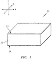
- FIG. 1 is a partial, perspective block diagram illustration of a structural, acoustic panel 20 for attenuating noise.
- This acoustic panel 20 may be configured to attenuate noise generated by an aircraft propulsion system such as, for example, a turbofan propulsion system or a turbojet propulsion system.
- the acoustic panel 20 may be configured with a nacelle of the propulsion system.
- the acoustic panel 20, for example may be configured as or with an inner or outer barrel, a translating sleeve of a thrust reverser, a blocker door, etc.
- the acoustic panel 20 may be configured with another component / structure of the aircraft such as its fuselage or a wing.
- the acoustic panel 20 may be configured to also or alternatively attenuate aircraft related noise other than that generated by the propulsion system.
- the acoustic panel 20 of the present disclosure may alternatively be configured for non-aircraft applications.
- the acoustic panel 20 extends longitudinally along a y-axis.
- the acoustic panel 20 extends laterally along an x-axis.
- the acoustic panel 20 extends vertically along a z-axis.
- the term "vertical" is used herein to describe a depthwise panel direction and is not limited to a gravitational up/down direction.
- the x-y plane is shown as a generally flat plane. However, in other embodiments, the x-y plane and, thus, the acoustic panel 20 may be curved and/or follow an undulating geometry.
- the x-y plane and, thus, the acoustic panel 20 may be arcuate, cylindrical or conical with or without radial undulations.
- the vertical direction may change at different locations along the x-y plane; e.g., the vertical direction may be a radial direction for a cylindrical, conical or spherical acoustic panel.
- the acoustic panel 20 includes an acoustic porous top skin 22 (e.g., a perforated face skin), a solid, non-perforated bottom skin 24 (e.g., a back skin) and a cellular core 26.
- top skin 22 e.g., a perforated face skin
- solid, non-perforated bottom skin 24 e.g., a back skin
- cellular core 26 e.g., cellular core 26.
- top and “bottom” are used in this disclosure to describe the relative position of an element as viewed in the figures. The present disclosure, however, is not limited to such an orientation.
- the cellular core 26 is disposed and extends vertically between the top skin 22 and the bottom skin 24.
- the cellular core 26 is also connected to the top skin 22 and the bottom skin 24.
- the cellular core 26, for example, may be welded, brazed, fused, adhered and/or otherwise bonded to the top skin 22 and/or the bottom skin 24.
- the cellular core 26 may also or alternatively be mechanically fastened to the top skin 22 and/or the bottom skin 24.
- the present disclosure is not limited to any particular manufacturing methods.
- the top skin 22 may be configured as a relatively thin sheet or layer of material that extends longitudinally and laterally along the x-y plane.
- This top skin 22 material may include, but is not limited to, a metal, a polymer, a fiber reinforced composite (e.g., fiberglass composite, carbon fiber composite, aramid fiber composite, etc.), or a combination thereof.
- the top skin 22 has a vertical thickness, which extends vertically between opposing first skin top and bottom side surfaces 28 and 30.
- the top skin 22 includes a plurality of perforations 32; e.g., apertures such as through-holes. Each of these perforations 32 extends generally vertically through the top skin 22 between its side surfaces 28 and 30. While the perforations 32 are described above and illustrated in FIG. 2 as through-holes for ease of description, one or more of the perforations 32 may also or alternatively be formed by one or more interconnected pores in the top skin 22 material.
- the bottom skin 24 may be configured as a relatively thin sheet or layer of (e.g., solid, continuous and/or uninterrupted) material that extends longitudinally and laterally along the x-y plane (see FIG. 1 ).
- This bottom skin 24 material may include, but is not limited to, a metal, a polymer, a fiber reinforced composite (e.g., fiberglass composite, carbon fiber composite, aramid fiber composite, etc.), or a combination thereof.
- the bottom skin 24 material may be the same as or different than the top skin 22 material.
- the bottom skin 24 has a vertical thickness, which extends vertically between opposing second skin top and bottom side surfaces 34 and 36. This vertical thickness may be substantially equal to or different (e.g., greater or less) than the vertical thickness of the top skin 22.
- the cellular core 26 extends longitudinally and laterally along the x-y plane.
- the cellular core 26 has a vertical thickness, which extends vertically between opposing core sides 38 and 40 respectively abutted against the top skin 22 and the bottom skin 24.
- the vertical thickness may be substantially greater than the vertical thickness of the top skin 22 and/or the bottom skin 24.
- the vertical thickness of the core 26, for example, may be at least ten to forty times (10-40x), or more, greater than the vertical thickness of the skin 22, 24; however, the acoustic panel 20 of the present disclosure is not limited to such an exemplary embodiment.
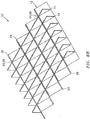
- the cellular core 26 includes a corrugated body 42, one or more top stringer bodies 44 and one or more bottom stringer bodies 46, where the top stringer bodies 44 and the bottom stringer bodies 46 are arranged on opposing sides of the corrugated body 42. More particularly, referring to FIG. 5 , the top stringer bodies 44 are disposed vertically between the corrugated body 42 and the top skin 22. The bottom stringer bodies 46 are disposed vertically between the corrugated body 42 and the bottom skin 24. Each of the bottom stringer bodies 46 is also aligned longitudinally with a respective one of the top stringer bodies 44 as seen in FIG. 4 .
- the corrugated body 42 of FIG. 5 includes a plurality of corrugations 48; see also FIG. 6 .
- These corrugations 48 along with the top stringer bodies 44 and the bottom stringer bodies 46 are arranged together to configure the cellular core 26 as an open cavity (e.g., open cell) structure.
- This open cavity structure forms a plurality of cavities 50 (see also FIG. 10 ) vertically between the top skin 22 and the bottom skin 24.
- Each of these cavities 50 may be fluidly coupled with one or more respective perforations 32 in the top skin 22 (see FIG. 5 ).
- the corrugations 48 are arranged in a laterally extending array. This arrangement provides the corrugated body 42 with an accordion wall structure. More particularly, the corrugations 48 are configured from at least a plurality of baffles 52 and a plurality of porous septums 54 (e.g., perforated septums). The corrugations 48 of FIGS. 5 and 6 are also configured from a plurality of top peak extensions 56 and/or a plurality of bottom peak extensions 58; however, in other embodiments, such extensions 56 and/or 58 may be omitted.
- Each of the baffles 52 may be configured as a solid, continuous and/or uninterrupted panel of core material.
- Each of the septum 54 may be configured as a panel of core material with one or more perforations 60; e.g., apertures such as through-holes. While these perforations 60 are described and illustrated in FIG. 5 as through-holes for ease of description, one or more of the perforations 60 may also or alternatively be formed by one or more interconnected pores in the septum 54 material.
- Each of the top peak extensions 56 may be configured as a solid, continuous and/or uninterrupted panel of core material.
- Each of the bottom peak extensions 58 may be configured as a solid, continuous and/or uninterrupted panel of core material.
- Each corrugation 48 includes a respective one of the baffles 52, a respective one of the septums 54, a respective one of the top peak extensions 56 and a respective one of the bottom peak extensions 58.
- Each of these corrugation portions 52, 54, 56 and 58 extends longitudinally along a longitudinal length of the respective corrugation 48 as shown in FIG. 6 .
- the top peak extension 56 extends laterally from a distal first end 62 to a second end 64.
- the first end 62 may be connected to a top end 66 of a septum 54 in a laterally adjacent one of the corrugations 48.
- the second end 64 is connected to a top end 68 of the baffle 52.
- the baffle 52 extends laterally and/or vertically (e.g., diagonally) from its top end 68 to a bottom end 70, which is connected to a first end 72 of the bottom peak extension 58.
- the bottom peak extension 58 extends laterally from its first end 72 to a second end 74, which is connected to a bottom end 76 of the septum 54.
- the septum 54 extends laterally and/or vertically (e.g., diagonally) from its bottom end 76 to its top end 66, which may be connected to the first end 62 of the top peak extension 56 in a laterally adjacent one of the corrugations 48.
- each corrugation 48 forms a top channel 78 within the corrugated body 42.
- This top channel 78 extends laterally between the baffle 52 and the septum 54.
- the top channel 78 extends vertically into the corrugated body 42 from the core side 38 to the bottom peak extension 58.
- the top channel 78 also extends longitudinally along the entire longitudinal length of the corrugation 48.
- Each laterally adjacent pair of the corrugations 48 also form a bottom channel 80 within the corrugated body 42.
- the bottom channel 80 extends laterally between the septum 54 of a first of the adjacent corrugations 48 to the baffle 52 of a second of the adjacent corrugations 48.
- the bottom channel 80 extends vertically into the corrugated body 42 from the core side 40 to the top peak extension 56 of the second of the adjacent corrugations 48.
- the bottom channel 80 also extends longitudinally along the entire longitudinal lengths of the adjacent corrugations 48.
- the top channels 78 and the bottom channels 80 are positioned on opposing sides of the corrugated body 42.
- each top stringer body 44 is discretely spaced longitudinally along the top channels 78 and the corrugations 48. Referring to FIGS. 3A and 5 , each top stringer body 44 extends laterally across one or more of the top channels 78 and the corrugations 48. For example, each top stringer body 44 includes one or more top sidewalls 82 arranged in a laterally extending array. Each top stringer body 44 also includes one or more top bridges 84.
- Each of the top bridges 84 extends laterally between and connects a respective laterally adjacent pair of the top sidewalls 82. Each of the top bridges 84 is configured to laterally cross a top peak 86 between laterally adjacent corrugations 48. In some embodiments, each top bridge 84 may be configured to cross over the top peak 86 as shown in FIG. 7 . In other embodiments, each top bridge 84 may be configured as a tongue (e.g., tenon, key, etc.) that is mated with and disposed in a groove 88 (e.g., a mortice, slot, etc.) in the top peak 86 as shown in FIG. 8A ; see also FIGS. 8B , 8C and 8D . In the embodiment of FIG.
- the groove 88 extends vertically through the respective top peak extension 56 and into the respective baffle 52 and septum 54. Furthermore, the tongue (e.g., 84) and the groove 88 are configured such that the respective top stringer body 44 and the corrugated body 42 are vertically flush at the core side 38.
- each top sidewall 82 is configured with a shape that substantially matches a cross-sectional shape of a respective one of the top channels 78; e.g., see FIG. 5 .
- Each top sidewall 82 is disposed within a respective one of the top channels 78 and configured to substantially fluidly isolate longitudinally adjacent portions of that top channel 78 from one another. More particularly, the top sidewall 82 extends laterally across the top channel 78 between the respective baffle 52 and the respective septum 54. The top sidewall 82 extends vertically into the top channel 78 to a respective top peak extension 56.
- the top sidewall 82 may also be attached (e.g., adhered and/or otherwise bonded) to one or more of the corrugated body portions 52, 54 and/or 58.
- This attachment may be a direct attachment as shown in FIG. 3A or through one or more intermediate members such as one or more of the flanges 90A and 90B shown in FIGS. 9A and 9B .
- each bottom stringer body 46 is discretely spaced longitudinally along the bottom channels 80 and the corrugations 48. Referring to FIGS. 3A and 4 , each bottom stringer body 46 extends laterally across one or more of the bottom channels 80 and the corrugations 48. For example, each bottom stringer body 46 includes one or more bottom sidewalls 92 arranged in a laterally extending array. Each bottom stringer body 46 also includes one or more bottom bridges 94.
- Each of the bottom bridges 94 extends laterally between and connects a respective laterally adjacent pair of the bottom sidewalls 92. Each of the bottom bridges 94 is configured to laterally cross a bottom peak 96 between laterally adjacent corrugations 48. In some embodiments, each bottom bridge 94 may be configured to cross over the bottom peak 96 as shown in FIG. 7 . In other embodiments, each bottom bridge 94 may be configured as a tongue (e.g., tenon, key, etc.) that is mated with and disposed in a groove 98 (e.g., a mortice, slot, etc.) in the bottom peak 96 as shown in FIG. 8 .
- a tongue e.g., tenon, key, etc.
- each bottom sidewall 92 is configured with a shape that substantially matches a cross-sectional shape of a respective one of the bottom channels 80; e.g., see FIG. 5 .
- Each bottom sidewall 92 is disposed within a respective one of the bottom channels 80 and configured to substantially fluidly isolate longitudinally adjacent portions of that bottom channel 80 from one another. More particularly, the bottom sidewall 92 extends laterally across the bottom channel 80 between respective baffle 52 and a respective septum 54. The bottom sidewall 92 extends vertically into the bottom channel 80 to a respective bottom peak extension 58.
- the bottom sidewall 92 may also be attached (e.g., adhered and/or otherwise bonded) to one or more of the corrugated body portions 52, 54 and/or 56. This attachment may be a direct attachment or through one or more intermediate members such as one or more of the flanges 90A and/or 90B; e.g., see FIGS. 9A and 9B .
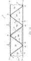
- each of the cavities 50 extends laterally between and is formed by a laterally adjacent pair of the baffles 52. Each of the cavities 50 extends vertically between the top skin 22 and the bottom skin 22. Referring to FIG. 3A , each of the cavities 50 extends longitudinally between a laterally adjacent pair of the top sidewalls 82 and a laterally adjacent pair of the bottom sidewalls 92. Referring again to FIG. 10 , each septum 54 is disposed within and divides a respective one of the cavities 50 into fluidly coupled sub-cavities 50A and 50B. More particularly, the perforations 60 in the septum 54 fluidly couple the sub-cavities 50A and 50B together.
- the top sub-cavity 50A corresponds to the portion of a respective one of the top channels 78 between the adjacent top sidewalls 82; see also FIGS. 3A and 6 .
- the bottom sub-cavity 50B corresponds to the portion of a respective one of the bottom channels 80 between the adjacent bottom sidewalls 92; see also FIGS. 3A and 6 .
- Each of the cavities 50 forms a resonance chamber.
- a length of the resonance chamber extends diagonally between the top skin 22 and the bottom skin 24 and through a respective one of the septums 54.
- the length of the resonance chamber therefore is longer than the vertical thickness of the cellular core 26. This enables noise attenuation of relatively low frequency noise without increasing the vertical thickness of the core 26 and, thus, a vertical thickness of the acoustic panel 20.
- each resonance chamber may receive acoustic waves through the perforations 32 in the top skin 22.
- the resonance chamber may reverse the phase of one or more frequencies of those sound waves using known acoustic reflection principles and subsequently direct the reverse phase sound waves out of the acoustic panel 20 through the perforations 32 to destructively interfere with other incoming acoustic waves.
- the corrugated body 42 may be constructed from any suitable material(s).
- the corrugated body 42 may be constructed from a metal, a polymer, a fiber reinforced composite (e.g., fiberglass composite, carbon fiber composite, aramid fiber composite, fiber reinforced plastic (FRP), metal matrix material, using continuous fibers, chopped fiber, particulates infused (e.g., nano tubes, etc.), paper such as that in a nomex core, etc.), or a combination thereof.
- the corrugated body 42 may be constructed from the same material(s) as the top skin 22 and/or the bottom skin 24, or a different material or materials.
- the top and/or bottom stringer bodies 44 and 46 may be constructed from any suitable material(s).
- the corrugated body 42 may be constructed from a metal (e.g., sheet metal), a polymer, a fiber reinforced composite (e.g., fiberglass composite, carbon fiber composite, aramid fiber composite, fiber reinforced plastic (FRP), metal matrix material, using continuous fibers, chopped fiber, particulates infused (e.g., nano tubes, etc.), paper such as that in a nomex core, etc.), or a combination thereof.
- One or more of the stringer bodies 44, 46 may be constructed from the same material(s) as the corrugated body 42, the top skin 22 and/or the bottom skin 24, or a different material or materials.
- the corrugated body 42 may be constructed from composite material whereas the stringer bodies 44, 46 may be constricted from the same type of composite material, a different type of composite material, polymer material or metal (e.g., stamped and/or folded sheet metal).
- each of the stringer bodies 44, 46 may be configured as an unsegmented, unitary body. Such a configuration may enable assembly personnel to quickly and efficiently assembly the cellular core 26.
- the configuration of the stringer bodies 44, 46 disclosed herein also lend to simply fabrication techniques; e.g., injection molding; sheet metal fabrication via cutting, stamping, bending; etc.
- one piece may be used to divide multiple channels 78, 80 since each stringer body 44, 46 extends laterally across multiple corrugations 48 and channels 78, 80.
- one or more of the stringer bodies 44, 46 may each be configured as a segmented body. Each of these stringer body 44, 46 segments may be configured as a discrete body, which collectively are aligned to provide the stringer body 44, 46. Each segment may be configured with one or more of the sidewalls 82, 92.
- the stringer bodies 44, 46 may be configured such that the sidewalls 82, 92 are substantially perpendicular to the top skin 22 and/or the bottom skin 24 (e.g., substantially vertical). However, in other embodiments, one or more of the stringer bodies 44, 46 may be configured such that the sidewalls 82, 92 are (e.g., acutely or obtusely) angled relative to the top skin 22 and/or the bottom skin 24.
- both the baffles 52 and the septums 54 may be (e.g., acutely or obtusely) angled relative to the top skin 22 and/or the bottom skin 24 as shown in FIG. 5 .
- the baffles 52 or the septums 54 may be substantially perpendicular to the top skin 22 and/or the bottom skin 24 (e.g., substantially vertical) as shown in FIG. 11 .
- each sidewall 82, 92 may have a single wall structure as shown in FIG. 12 .
- each sidewall 82, 92 may have a multi-wall (e.g., double wall) structure as shown in FIG. 13 where, for example, the respective stringer body 44, 46 is formed from a folded over piece of sheet metal.
- the width of intermediate portion 99 is exaggerated for ease of illustration. Typically, the intermediate portion 99 width will be minimized to reduce space between layers 101 of the sidewall.
- the intermediate portion 99 may be a fold line such that the layers 101 of the sidewall are essentially touching one another.
- the present disclosure is not limited to such embodiments; e.g., there may be spacing between the layers 101 of the sidewall.
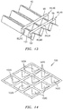
- the stringer bodies 44, 46 are described above and being generally planar; e.g., generally lying in the vertical-lateral plane. However, in other embodiments, a single stringer body 100 may be configured to also extend into the longitudinal plane. Such a configuration enables that single stringer body 100 to also include a plurality of sidewalls 102A, 102B or 102C (generally referred to as 102) in the same channel 78, 80 as shown in FIG. 14 .
- the stringer body 100 of FIG. 14 is also configured to extend longitudinally along a plurality of the channels 78, 80 and arranged a plurality of sidewalls 102 respectively in each of those channels 78, 80.
Abstract
Description
- This disclosure relates generally to noise attenuation and, more particularly, to an acoustic panel (sometimes also referred to as "an acoustic liner" for attenuating noise generated by, for example, a gas turbine engine for an aircraft propulsion system.
- Acoustic panels may be used in various applications to attenuate noise. An acoustic panel, for example, may be configured with a nacelle of an aircraft propulsion system to attenuate noise generated by a gas turbine engine. Such an acoustic panel typically includes a honeycomb core connected between a perforated face skin and a solid, non-perforated back skin. The honeycomb core includes a plurality of resonating chambers. These resonating chambers are tuned by selecting a desired chamber length and, thus, core thickness that corresponds to a specific target frequency of noise to be attenuated. Increasing the core thickness, for example, will typically tune the resonating chambers for attenuating lower frequency noise. Conversely, decreasing the core thickness will typically tune the resonating chambers to attenuate higher frequency noise.
- Recent trends in aircraft engine design such as higher bypass ratios, larger fan diameters, slower rotating fans and/or fewer number of fan blades have resulted in those aircraft engines generating relatively low frequency noise. Relatively strict space constraints (e.g., loft envelope) for those engines, however, typically limit or prohibit increasing the thickness of an acoustic panel to tune its resonating chambers for such relatively low frequency noise. There is a need in the art therefore for an acoustic panel operable to attenuate relatively low frequency noise while utilizing the same or less space than previous acoustic panels. There is a further need to provide a panel configuration capable of reducing panel assembly time, complexity and cost.
- According to an aspect of the present disclosure, a panel is provided for attenuating noise. This panel includes a porous first skin, a second skin and a core connected between the porous first skin and the second skin. The core includes a corrugated body and a plurality of stringer bodies. The corrugated body includes a plurality of corrugations configured from at least a plurality of baffles and a plurality of porous septums. Each of the corrugations includes a respective one of the baffles and a respective one of the porous septums. A first of the corrugations forms a first channel that extends laterally between a first of the baffles and a first of the porous septums. The stringer bodies are spaced longitudinally along the first channel. Each of the stringer bodies is configured as or otherwise includes a first sidewall disposed within the first channel and configured to fluidly isolate longitudinally adjacent portions of the first channel from one another.
- According to another aspect of the present disclosure, another panel is provided for attenuating noise. This panel includes a first skin configured with a plurality of perforations. The panel also includes a second skin and a core connected between the first skin and the second skin. The core includes a corrugated body and a stringer body. The corrugated body includes a plurality of channels and a plurality of corrugations configured from at least a plurality of baffles and a plurality of porous septums. Each of the corrugations includes a respective one of the baffles and a respective one of the porous septums. Each of the corrugations forms a respective one of the channels. The stringer body extends laterally across the channels. The stringer body includes a plurality of sidewalls. Each of the sidewalls is configured to fluidly isolate longitudinally adjacent portions of a respective one of the channels from one another.
- The corrugated body may include a plurality of second channels. The core may include a second stringer body that includes a plurality of second sidewalls. Each of the second sidewalls may be configured to fluidly isolate longitudinally adjacent portions of a respective one of the second channels from one another. The corrugated body may be between the stringer body and the second stringer body.
- A second of the corrugations may form a second channel that extends laterally between a second of the baffles and a second of the porous septums. Each of the stringer bodies may be configured as or otherwise include a second sidewall disposed within the second channel and configured to fluidly isolate longitudinally adjacent portions of the second channel from one another.
- Each of the stringer bodies may extend laterally across the first of the corrugations and a second of the corrugations.
- The first sidewall of each of the stringer bodies may extend from the porous first skin to the first of the baffles and the first of the porous septums.
- The first sidewall of each of the stringer bodies may extend from the second skin to the first of the baffles and the first of the porous septums.
- A second channel may extend laterally between the first of the porous septums and a second of the baffles. The core may include a plurality of second stringer bodies. Each of the second stringer bodies may be configured as or otherwise include a second sidewall disposed within the second channel and configured to fluidly isolate longitudinally adjacent portions of the second channel from one another.
- The first channel and the second channel may be on opposing sides of the corrugated body.
- A cavity may extend laterally between the first of the baffles and the second of the baffles and be fluidly coupled with perforations in the porous first skin. The first septum may extend from the porous first skin and the first of the baffles to the second skin and the second of the baffles, and/or may divide the cavity into fluidly coupled first and second sub-cavities. The first sub-cavity may extend longitudinally between the first sidewalls of an adjacent pair of the stringer bodies. The second sub-cavity may extend longitudinally between the second sidewalls of an adjacent pair of the second stringer bodies.
- Each of the stringer bodies may include a tongue laterally connected to the first sidewall. The tongue may be mated with a respective groove in a peak formed by the first of the baffles and a second of the porous septums.
- A second of the corrugations may form a second channel that extends laterally between a second of the baffles and the second of the porous septums. Each of the stringer bodies may be configured as or otherwise include a second sidewall disposed within the second channel and configured to fluidly isolate longitudinally adjacent portions of the second channel from one another. The tongue may be configured as a bridge that extends laterally between and connects the first sidewall and the second sidewall.
- A second of the corrugations may form a second channel that extends laterally between a second of the baffles and a second of the porous septums. Each of the stringer bodies may be configured as or otherwise include a second sidewall and a bridge. The side sidewall may be disposed within the second channel and configured to fluidly isolate longitudinally adjacent portions of the second channel from one another. The bridge may extend laterally between and connect the first sidewall and the second sidewall.
- The bridge may lay over a peak formed by the first of the baffles and the second of the porous septums.
- The first sidewall may be configured as a single wall structure.
- The first sidewall may be configured as a multi-wall structure.
- Each of the stringer bodies may include a tab that projects out from the first sidewall and is attached to the corrugated body.
- Each of the stringer bodies may be formed from sheet metal.
- The corrugated structure may be configured from or otherwise include composite material. Each of the stringer bodies may be configured from or otherwise include metal.
- Each of the stringer bodies may be configured from or otherwise include polymer.
- The foregoing features and the operation of the invention will become more apparent in light of the following description and the accompanying drawings.
-
-
FIG. 1 is a partial, perspective block diagram illustration of a structural, acoustic panel for attenuating noise. -
FIG. 2 is a sectional schematic illustration of a portion of the acoustic panel taken along line 2-2 inFIG. 3A . -
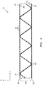
FIG. 3A is a perspective illustration of a portion of a cellular core for the acoustic panel. -
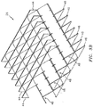
FIG. 3B is an exploded perspective illustration of the cellular core ofFIG. 3A . -
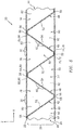
FIG. 4 is a sectional illustration of the cellular core ofFIG. 3A taken along the line 4-4 inFIG. 3A . -
FIG. 5 is a sectional schematic illustration of another portion of the acoustic panel taken along line 5-5 inFIG. 3A . -
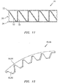
FIG. 6 is a perspective illustration of a corrugated body. -
FIG. 7 is sectional schematic illustration of a portion of an alternative acoustic panel. -
FIGS. 8A-8D are illustrations of portions of another alternative acoustic panel. -
FIGS. 9A and 9B are perspective illustrations of portions of alternative stringer bodies. -
FIG. 10 is another sectional schematic illustration of the portion of the acoustic panel taken along line 5-5 inFIG. 3A . -
FIG. 11 is a sectional schematic illustration of a portion of an alternative acoustic panel. -
FIG. 12 is a perspective illustration of a stringer body. -
FIG. 13 is a perspective illustration of alternative stringer bodies bonded to a corrugated body. -
FIG. 14 is a perspective illustration of another alternative stringer body. -
FIG. 1 is a partial, perspective block diagram illustration of a structural,acoustic panel 20 for attenuating noise. Thisacoustic panel 20 may be configured to attenuate noise generated by an aircraft propulsion system such as, for example, a turbofan propulsion system or a turbojet propulsion system. With such a configuration, theacoustic panel 20 may be configured with a nacelle of the propulsion system. Theacoustic panel 20, for example, may be configured as or with an inner or outer barrel, a translating sleeve of a thrust reverser, a blocker door, etc. Alternatively, theacoustic panel 20 may be configured with another component / structure of the aircraft such as its fuselage or a wing. Furthermore, theacoustic panel 20 may be configured to also or alternatively attenuate aircraft related noise other than that generated by the propulsion system. Theacoustic panel 20 of the present disclosure, however, may alternatively be configured for non-aircraft applications. - The
acoustic panel 20 extends longitudinally along a y-axis. Theacoustic panel 20 extends laterally along an x-axis. Theacoustic panel 20 extends vertically along a z-axis. The term "vertical" is used herein to describe a depthwise panel direction and is not limited to a gravitational up/down direction. Furthermore, for ease of illustration, the x-y plane is shown as a generally flat plane. However, in other embodiments, the x-y plane and, thus, theacoustic panel 20 may be curved and/or follow an undulating geometry. For example, the x-y plane and, thus, theacoustic panel 20 may be arcuate, cylindrical or conical with or without radial undulations. Thus, the vertical direction may change at different locations along the x-y plane; e.g., the vertical direction may be a radial direction for a cylindrical, conical or spherical acoustic panel. - The
acoustic panel 20 includes an acoustic porous top skin 22 (e.g., a perforated face skin), a solid, non-perforated bottom skin 24 (e.g., a back skin) and acellular core 26. Note, the terms "top" and "bottom" are used in this disclosure to describe the relative position of an element as viewed in the figures. The present disclosure, however, is not limited to such an orientation. - Briefly, the
cellular core 26 is disposed and extends vertically between thetop skin 22 and thebottom skin 24. Thecellular core 26 is also connected to thetop skin 22 and thebottom skin 24. Thecellular core 26, for example, may be welded, brazed, fused, adhered and/or otherwise bonded to thetop skin 22 and/or thebottom skin 24. Thecellular core 26 may also or alternatively be mechanically fastened to thetop skin 22 and/or thebottom skin 24. However, the present disclosure is not limited to any particular manufacturing methods. - The
top skin 22 may be configured as a relatively thin sheet or layer of material that extends longitudinally and laterally along the x-y plane. Thistop skin 22 material may include, but is not limited to, a metal, a polymer, a fiber reinforced composite (e.g., fiberglass composite, carbon fiber composite, aramid fiber composite, etc.), or a combination thereof. Referring now toFIG. 2 , thetop skin 22 has a vertical thickness, which extends vertically between opposing first skin top and bottom side surfaces 28 and 30. Thetop skin 22 includes a plurality ofperforations 32; e.g., apertures such as through-holes. Each of theseperforations 32 extends generally vertically through thetop skin 22 between its side surfaces 28 and 30. While theperforations 32 are described above and illustrated inFIG. 2 as through-holes for ease of description, one or more of theperforations 32 may also or alternatively be formed by one or more interconnected pores in thetop skin 22 material. - The
bottom skin 24 may be configured as a relatively thin sheet or layer of (e.g., solid, continuous and/or uninterrupted) material that extends longitudinally and laterally along the x-y plane (seeFIG. 1 ). Thisbottom skin 24 material may include, but is not limited to, a metal, a polymer, a fiber reinforced composite (e.g., fiberglass composite, carbon fiber composite, aramid fiber composite, etc.), or a combination thereof. Thebottom skin 24 material may be the same as or different than thetop skin 22 material. Thebottom skin 24 has a vertical thickness, which extends vertically between opposing second skin top and bottom side surfaces 34 and 36. This vertical thickness may be substantially equal to or different (e.g., greater or less) than the vertical thickness of thetop skin 22. - Referring to
FIG. 3A (see alsoFIG. 3B ), thecellular core 26 extends longitudinally and laterally along the x-y plane. Referring again toFIG. 2 , thecellular core 26 has a vertical thickness, which extends vertically between opposingcore sides top skin 22 and thebottom skin 24. The vertical thickness may be substantially greater than the vertical thickness of thetop skin 22 and/or thebottom skin 24. The vertical thickness of the core 26, for example, may be at least ten to forty times (10-40x), or more, greater than the vertical thickness of theskin acoustic panel 20 of the present disclosure is not limited to such an exemplary embodiment. - Referring to
FIGS. 3A ,4 and5 , thecellular core 26 includes acorrugated body 42, one or moretop stringer bodies 44 and one or morebottom stringer bodies 46, where thetop stringer bodies 44 and thebottom stringer bodies 46 are arranged on opposing sides of thecorrugated body 42. More particularly, referring toFIG. 5 , thetop stringer bodies 44 are disposed vertically between thecorrugated body 42 and thetop skin 22. Thebottom stringer bodies 46 are disposed vertically between thecorrugated body 42 and thebottom skin 24. Each of thebottom stringer bodies 46 is also aligned longitudinally with a respective one of thetop stringer bodies 44 as seen inFIG. 4 . - The
corrugated body 42 ofFIG. 5 includes a plurality ofcorrugations 48; see alsoFIG. 6 . Thesecorrugations 48 along with thetop stringer bodies 44 and thebottom stringer bodies 46 are arranged together to configure thecellular core 26 as an open cavity (e.g., open cell) structure. This open cavity structure forms a plurality of cavities 50 (see alsoFIG. 10 ) vertically between thetop skin 22 and thebottom skin 24. Each of thesecavities 50 may be fluidly coupled with one or morerespective perforations 32 in the top skin 22 (seeFIG. 5 ). - Referring to
FIGS. 5 and6 , thecorrugations 48 are arranged in a laterally extending array. This arrangement provides thecorrugated body 42 with an accordion wall structure. More particularly, thecorrugations 48 are configured from at least a plurality ofbaffles 52 and a plurality of porous septums 54 (e.g., perforated septums). Thecorrugations 48 ofFIGS. 5 and6 are also configured from a plurality oftop peak extensions 56 and/or a plurality ofbottom peak extensions 58; however, in other embodiments,such extensions 56 and/or 58 may be omitted. - Each of the
baffles 52 may be configured as a solid, continuous and/or uninterrupted panel of core material. Each of theseptum 54 may be configured as a panel of core material with one ormore perforations 60; e.g., apertures such as through-holes. While theseperforations 60 are described and illustrated inFIG. 5 as through-holes for ease of description, one or more of theperforations 60 may also or alternatively be formed by one or more interconnected pores in theseptum 54 material. Each of thetop peak extensions 56 may be configured as a solid, continuous and/or uninterrupted panel of core material. Each of thebottom peak extensions 58 may be configured as a solid, continuous and/or uninterrupted panel of core material. - Each
corrugation 48 includes a respective one of thebaffles 52, a respective one of theseptums 54, a respective one of thetop peak extensions 56 and a respective one of thebottom peak extensions 58. Each of thesecorrugation portions respective corrugation 48 as shown inFIG. 6 . - Referring to
FIG. 5 , thetop peak extension 56 extends laterally from a distal first end 62 to a second end 64. The first end 62 may be connected to a top end 66 of aseptum 54 in a laterally adjacent one of thecorrugations 48. The second end 64 is connected to a top end 68 of thebaffle 52. Thebaffle 52 extends laterally and/or vertically (e.g., diagonally) from its top end 68 to a bottom end 70, which is connected to a first end 72 of thebottom peak extension 58. Thebottom peak extension 58 extends laterally from its first end 72 to a second end 74, which is connected to a bottom end 76 of theseptum 54. Theseptum 54 extends laterally and/or vertically (e.g., diagonally) from its bottom end 76 to its top end 66, which may be connected to the first end 62 of thetop peak extension 56 in a laterally adjacent one of thecorrugations 48. - Referring to
FIG. 6 , each corrugation 48 forms atop channel 78 within thecorrugated body 42. Thistop channel 78 extends laterally between thebaffle 52 and theseptum 54. Thetop channel 78 extends vertically into thecorrugated body 42 from thecore side 38 to thebottom peak extension 58. Thetop channel 78 also extends longitudinally along the entire longitudinal length of thecorrugation 48. - Each laterally adjacent pair of the
corrugations 48 also form abottom channel 80 within thecorrugated body 42. Thebottom channel 80 extends laterally between theseptum 54 of a first of theadjacent corrugations 48 to thebaffle 52 of a second of theadjacent corrugations 48. Thebottom channel 80 extends vertically into thecorrugated body 42 from thecore side 40 to thetop peak extension 56 of the second of theadjacent corrugations 48. Thebottom channel 80 also extends longitudinally along the entire longitudinal lengths of theadjacent corrugations 48. Thetop channels 78 and thebottom channels 80 are positioned on opposing sides of thecorrugated body 42. - Referring to
FIG. 3A , thetop stringer bodies 44 are discretely spaced longitudinally along thetop channels 78 and thecorrugations 48. Referring toFIGS. 3A and5 , eachtop stringer body 44 extends laterally across one or more of thetop channels 78 and thecorrugations 48. For example, eachtop stringer body 44 includes one or moretop sidewalls 82 arranged in a laterally extending array. Eachtop stringer body 44 also includes one or moretop bridges 84. - Each of the
top bridges 84 extends laterally between and connects a respective laterally adjacent pair of thetop sidewalls 82. Each of thetop bridges 84 is configured to laterally cross atop peak 86 between laterallyadjacent corrugations 48. In some embodiments, eachtop bridge 84 may be configured to cross over thetop peak 86 as shown inFIG. 7 . In other embodiments, eachtop bridge 84 may be configured as a tongue (e.g., tenon, key, etc.) that is mated with and disposed in a groove 88 (e.g., a mortice, slot, etc.) in thetop peak 86 as shown inFIG. 8A ; see alsoFIGS. 8B ,8C and 8D . In the embodiment ofFIG. 8A , thegroove 88 extends vertically through the respectivetop peak extension 56 and into therespective baffle 52 andseptum 54. Furthermore, the tongue (e.g., 84) and thegroove 88 are configured such that the respectivetop stringer body 44 and thecorrugated body 42 are vertically flush at thecore side 38. - Referring again to
FIGS. 3A and4 , eachtop sidewall 82 is configured with a shape that substantially matches a cross-sectional shape of a respective one of thetop channels 78; e.g., seeFIG. 5 . Eachtop sidewall 82 is disposed within a respective one of thetop channels 78 and configured to substantially fluidly isolate longitudinally adjacent portions of thattop channel 78 from one another. More particularly, thetop sidewall 82 extends laterally across thetop channel 78 between therespective baffle 52 and therespective septum 54. Thetop sidewall 82 extends vertically into thetop channel 78 to a respectivetop peak extension 56. Thetop sidewall 82 may also be attached (e.g., adhered and/or otherwise bonded) to one or more of thecorrugated body portions FIG. 3A or through one or more intermediate members such as one or more of theflanges FIGS. 9A and 9B . - Referring to
FIG. 3A , thebottom stringer bodies 46 are discretely spaced longitudinally along thebottom channels 80 and thecorrugations 48. Referring toFIGS. 3A and4 , eachbottom stringer body 46 extends laterally across one or more of thebottom channels 80 and thecorrugations 48. For example, eachbottom stringer body 46 includes one or morebottom sidewalls 92 arranged in a laterally extending array. Eachbottom stringer body 46 also includes one or more bottom bridges 94. - Each of the bottom bridges 94 extends laterally between and connects a respective laterally adjacent pair of the
bottom sidewalls 92. Each of the bottom bridges 94 is configured to laterally cross abottom peak 96 between laterallyadjacent corrugations 48. In some embodiments, eachbottom bridge 94 may be configured to cross over thebottom peak 96 as shown inFIG. 7 . In other embodiments, eachbottom bridge 94 may be configured as a tongue (e.g., tenon, key, etc.) that is mated with and disposed in a groove 98 (e.g., a mortice, slot, etc.) in thebottom peak 96 as shown inFIG. 8 . - Referring again to
FIGS. 3A and4 , eachbottom sidewall 92 is configured with a shape that substantially matches a cross-sectional shape of a respective one of thebottom channels 80; e.g., seeFIG. 5 . Eachbottom sidewall 92 is disposed within a respective one of thebottom channels 80 and configured to substantially fluidly isolate longitudinally adjacent portions of thatbottom channel 80 from one another. More particularly, thebottom sidewall 92 extends laterally across thebottom channel 80 betweenrespective baffle 52 and arespective septum 54. Thebottom sidewall 92 extends vertically into thebottom channel 80 to a respectivebottom peak extension 58. Thebottom sidewall 92 may also be attached (e.g., adhered and/or otherwise bonded) to one or more of thecorrugated body portions flanges 90A and/or 90B; e.g., seeFIGS. 9A and 9B . - Referring to
FIG. 10 , each of thecavities 50 extends laterally between and is formed by a laterally adjacent pair of thebaffles 52. Each of thecavities 50 extends vertically between thetop skin 22 and thebottom skin 22. Referring toFIG. 3A , each of thecavities 50 extends longitudinally between a laterally adjacent pair of thetop sidewalls 82 and a laterally adjacent pair of thebottom sidewalls 92. Referring again toFIG. 10 , eachseptum 54 is disposed within and divides a respective one of thecavities 50 into fluidly coupled sub-cavities 50A and 50B. More particularly, theperforations 60 in theseptum 54 fluidly couple the sub-cavities 50A and 50B together. Thetop sub-cavity 50A corresponds to the portion of a respective one of thetop channels 78 between the adjacenttop sidewalls 82; see alsoFIGS. 3A and6 . Thebottom sub-cavity 50B corresponds to the portion of a respective one of thebottom channels 80 between the adjacent bottom sidewalls 92; see alsoFIGS. 3A and6 . - Each of the
cavities 50 forms a resonance chamber. A length of the resonance chamber extends diagonally between thetop skin 22 and thebottom skin 24 and through a respective one of theseptums 54. The length of the resonance chamber therefore is longer than the vertical thickness of thecellular core 26. This enables noise attenuation of relatively low frequency noise without increasing the vertical thickness of thecore 26 and, thus, a vertical thickness of theacoustic panel 20. For example, each resonance chamber may receive acoustic waves through theperforations 32 in thetop skin 22. The resonance chamber may reverse the phase of one or more frequencies of those sound waves using known acoustic reflection principles and subsequently direct the reverse phase sound waves out of theacoustic panel 20 through theperforations 32 to destructively interfere with other incoming acoustic waves. - The
corrugated body 42 may be constructed from any suitable material(s). Thecorrugated body 42, for example, may be constructed from a metal, a polymer, a fiber reinforced composite (e.g., fiberglass composite, carbon fiber composite, aramid fiber composite, fiber reinforced plastic (FRP), metal matrix material, using continuous fibers, chopped fiber, particulates infused (e.g., nano tubes, etc.), paper such as that in a nomex core, etc.), or a combination thereof. Thecorrugated body 42 may be constructed from the same material(s) as thetop skin 22 and/or thebottom skin 24, or a different material or materials. - The top and/or
bottom stringer bodies corrugated body 42, for example, may be constructed from a metal (e.g., sheet metal), a polymer, a fiber reinforced composite (e.g., fiberglass composite, carbon fiber composite, aramid fiber composite, fiber reinforced plastic (FRP), metal matrix material, using continuous fibers, chopped fiber, particulates infused (e.g., nano tubes, etc.), paper such as that in a nomex core, etc.), or a combination thereof. One or more of thestringer bodies corrugated body 42, thetop skin 22 and/or thebottom skin 24, or a different material or materials. For example, thecorrugated body 42 may be constructed from composite material whereas thestringer bodies - In some embodiments, each of the
stringer bodies cellular core 26. The configuration of thestringer bodies multiple channels stringer body multiple corrugations 48 andchannels stringer bodies stringer body stringer body sidewalls - In some embodiments, the
stringer bodies sidewalls top skin 22 and/or the bottom skin 24 (e.g., substantially vertical). However, in other embodiments, one or more of thestringer bodies sidewalls top skin 22 and/or thebottom skin 24. - In some embodiments, both the
baffles 52 and theseptums 54 may be (e.g., acutely or obtusely) angled relative to thetop skin 22 and/or thebottom skin 24 as shown inFIG. 5 . However, in other embodiments, thebaffles 52 or theseptums 54 may be substantially perpendicular to thetop skin 22 and/or the bottom skin 24 (e.g., substantially vertical) as shown inFIG. 11 . - In some embodiments, each
sidewall FIG. 12 . In other embodiments, eachsidewall FIG. 13 where, for example, therespective stringer body intermediate portion 99 is exaggerated for ease of illustration. Typically, theintermediate portion 99 width will be minimized to reduce space betweenlayers 101 of the sidewall. For example, in some embodiments, theintermediate portion 99 may be a fold line such that thelayers 101 of the sidewall are essentially touching one another. Of course, the present disclosure is not limited to such embodiments; e.g., there may be spacing between thelayers 101 of the sidewall. - The
stringer bodies single stringer body 100 may be configured to also extend into the longitudinal plane. Such a configuration enables thatsingle stringer body 100 to also include a plurality of sidewalls 102A, 102B or 102C (generally referred to as 102) in thesame channel FIG. 14 . Thestringer body 100 ofFIG. 14 , for example, is also configured to extend longitudinally along a plurality of thechannels channels - While various embodiments of the present invention have been disclosed, it will be apparent to those of ordinary skill in the art that many more embodiments and implementations are possible within the scope of the invention. For example, the present invention as described herein includes several aspects and embodiments that include particular features. Although these features may be described individually, it is within the scope of the present invention that some or all of these features may be combined with any one of the aspects and remain within the scope of the invention. Accordingly, the present invention is not to be restricted except in light of the attached claims and their equivalents.
Claims (15)
- A panel (20) for attenuating noise, comprising:a porous first skin (22);a second skin (24); anda core (26) connected between the porous first skin (22) and the second skin (24), the core (26) including a corrugated body (42) and a plurality of stringer bodies (44,46);the corrugated body (42) including a plurality of corrugations (48) configured from at least a plurality of baffles (52) and a plurality of porous septums (54), each of the corrugations (48) including a respective one of the baffles (52) and a respective one of the porous septums (54), wherein a first of the corrugations (48) forms a first channel (78) that extends laterally between a first of the baffles (52) and a first of the porous septums (54); andthe stringer bodies (44) spaced longitudinally along the first channel (78), each of the stringer bodies (44) comprising a first sidewall (82) disposed within the first channel (78) and configured to fluidly isolate longitudinally adjacent portions of the first channel (78) from one another.
- The panel of claim 1, wherein
a second of the corrugations (48) forms a second channel (78) that extends laterally between a second of the baffles (52) and a second of the porous septums (54); and
each of the stringer bodies (44) comprising a second sidewall (82) disposed within the second channel (78) and configured to fluidly isolate longitudinally adjacent portions of the second channel (78) from one another. - The panel of claim 1 or 2, wherein each of the stringer bodies (44,46) extends laterally across the first of the corrugations (48) and a second of the corrugations (48).
- The panel of any preceding claim, wherein the first sidewall (82) of each of the stringer bodies (44,46) extends from the porous first skin (22) or from the second skin (24) to the first of the baffles (52) and the first of the porous septums (54).
- The panel of claim 1, wherein
a second channel (80) extends laterally between the first of the porous septums (54) and a second of the baffles (52);
the core (26) further includes a plurality of second stringer bodies (46);
each of the second stringer bodies (46) comprising a second sidewall (92) disposed within the second channel (80) and configured to fluidly isolate longitudinally adjacent portions of the second channel (80) from one another. - The panel of claim 5, wherein the first channel (78) and the second channel (80) are on opposing sides of the corrugated body (42).
- The panel of claim 5 or 6, wherein
a cavity (50) extends laterally between the first of the baffles (52) and the second of the baffles (52) and is fluidly coupled with perforations (32) in the porous first skin (22);
the first septum (54) extending from the porous first skin (22) and the first of the baffles (52) to the second skin (24) and the second of the baffles (52), and dividing the cavity (50) into fluidly coupled first and second sub-cavities (52A,B);
the first sub-cavity (52A) extends longitudinally between the first sidewalls (82) of an adjacent pair of the stringer bodies (44); and
the second sub-cavity (52B) extends longitudinally between the second sidewalls (92) of an adjacent pair of the second stringer bodies (46). - The panel of any preceding claim, wherein each of the stringer bodies (44) further includes a tongue (84) laterally connected to the first sidewall (82), and the tongue (84) is mated with a respective groove (88) in a peak (86) formed by the first of the baffles (52) and a second of the porous septums (54).
- The panel of claim 8, wherein
a second of the corrugations (48) forms a or the second channel (78) that extends laterally between a second of the baffles (52) and the second of the porous septums (54);
each of the stringer bodies (44) comprising a or the second sidewall (82) disposed within the second channel (78) and configured to fluidly isolate longitudinally adjacent portions of the second channel (78) from one another, and the tongue (84) is configured as a bridge (84) that extends laterally between and connects the first sidewall (82) and the second sidewall (82). - The panel of claim 1, wherein
a second of the corrugations (48) forms a second channel (78) that extends laterally between a second of the baffles (52) and a second of the porous septums (54);
each of the stringer bodies (44) comprising a second sidewall (82) and a bridge (84);
the second sidewall (82) is disposed within the second channel (78) and configured to fluidly isolate longitudinally adjacent portions of the second channel (78) from one another; and
the bridge (84) extends laterally between and connects the first sidewall (82) and the second sidewall (82), optionally, wherein the bridge (84) lays over a peak (86) formed by the first of the baffles (52) and the second of the porous septums (54). - The panel of any preceding claim, wherein the first sidewall (82) is configured as a single wall structure or as a multi-wall structure.
- The panel of any preceding claim, wherein each of the stringer bodies (44) further includes a tab that projects out from the first sidewall (82) and is attached to the corrugated body (42).
- The panel of any preceding claim, wherein each of the stringer bodies (44,46) is formed from sheet metal, or comprises polymer.
- The panel of any preceding claim, wherein
the corrugated body (42) comprises composite material; and
each of the stringer bodies (44,46) comprises metal. - A panel (20) for attenuating noise, comprising:a first skin (22) configured with a plurality of perforations (32);a second skin (24); anda core (26) connected between the first skin (22) and the second skin (24), the core including a corrugated body (42) and a stringer body (100);the corrugated body (42) including a plurality of channels (78;80) and a plurality of corrugations (48) configured from at least a plurality of baffles (52) and a plurality of porous septums (54), each of the corrugations (48) including a respective one of the baffles (52) and a respective one of the porous septums (54), and each of the corrugations (48) forming a respective one of the channels (78;80); andthe stringer body (100) extending laterally across the channels (78;80) and comprising a plurality of sidewalls (102A,B,C), wherein each of the sidewalls (102A,B,C) is configured to fluidly isolate longitudinally adjacent portions of a respective one of the channels (78;80) from one another, optionally wherein:the corrugated body (48) further includes a plurality of second channels (80;78);the core (26) further includes a second stringer body (100) comprising a plurality of second sidewalls (102A,B,C);each of the second sidewalls (102A,B,C) is configured to fluidly isolate longitudinally adjacent portions of a respective one of the second channels (80;78) from one another; andthe corrugated body (48) is between the stringer body (100) and the second stringer body (100).
Applications Claiming Priority (1)
| Application Number | Priority Date | Filing Date | Title |
|---|---|---|---|
| US15/355,975 US10309305B2 (en) | 2016-11-18 | 2016-11-18 | Acoustic panel with sidewall stringers |
Publications (2)
| Publication Number | Publication Date |
|---|---|
| EP3324400A1 true EP3324400A1 (en) | 2018-05-23 |
| EP3324400B1 EP3324400B1 (en) | 2023-09-06 |
Family
ID=60413089
Family Applications (1)
| Application Number | Title | Priority Date | Filing Date |
|---|---|---|---|
| EP17202635.3A Active EP3324400B1 (en) | 2016-11-18 | 2017-11-20 | Acoustic panel with sidewall stringers |
Country Status (2)
| Country | Link |
|---|---|
| US (1) | US10309305B2 (en) |
| EP (1) | EP3324400B1 (en) |
Families Citing this family (17)
| Publication number | Priority date | Publication date | Assignee | Title |
|---|---|---|---|---|
| FR3070308B1 (en) * | 2017-08-25 | 2021-04-09 | Safran Nacelles | STRUCTURAL AND / OR ACOUSTIC PANEL OF AN AIRCRAFT PROPULSIVE NACELLE ASSEMBLY AND RELATED MANUFACTURING PROCESS |
| US10906659B2 (en) | 2018-04-03 | 2021-02-02 | Rohr, Inc. | Structured panel with structural reinforcement(s) |
| US11066147B2 (en) | 2018-07-10 | 2021-07-20 | Rohr, Inc. | Structured panel with integrated skin and sidewalls |
| US11261786B2 (en) * | 2018-08-06 | 2022-03-01 | Rohr, Inc. | Continuous slanted cell septum |
| USD887965S1 (en) * | 2018-11-22 | 2020-06-23 | Michael Ross Catania | Solar panel |
| USD887966S1 (en) * | 2018-11-22 | 2020-06-23 | Michael Ross Catania | Solar panel |
| USD883193S1 (en) * | 2018-11-28 | 2020-05-05 | Michael Ross Catania | Solar panel |
| US11242822B2 (en) * | 2018-12-14 | 2022-02-08 | Rohr, Inc. | Structured panel with multi-panel structure(s) |
| US11398214B2 (en) | 2018-12-14 | 2022-07-26 | Rohr, Inc. | Forming a structured panel with one or more structural reinforcements |
| USD883194S1 (en) * | 2018-12-16 | 2020-05-05 | Michael Ross Catania | Solar panel |
| US11572850B2 (en) * | 2019-06-04 | 2023-02-07 | Rohr, Inc. | Acoustic panel with one or more structural stiffeners |
| US11014331B2 (en) | 2019-08-05 | 2021-05-25 | Rohr, Inc. | Structured panel with non-parallel cavity walls |
| US20220099121A1 (en) * | 2020-09-25 | 2022-03-31 | Caterpillar Inc. | Panel assembly and aftertreatment assembly including panel assembly |
| CN112509544A (en) * | 2020-11-06 | 2021-03-16 | 北京朗新明环保科技有限公司 | Low-frequency noise reduction structure for light metal |
| US11965465B2 (en) | 2020-12-22 | 2024-04-23 | Rohr, Inc. | Acoustic panel with multiple layer corrugated core |
| US11715450B2 (en) | 2020-12-22 | 2023-08-01 | Rohr, Inc. | Acoustic panel core cell with funnel shaped septum |
| US11869472B2 (en) | 2021-08-02 | 2024-01-09 | Rohr, Inc. | Acoustic panel with reconfigurable chamber constrictions |
Citations (4)
| Publication number | Priority date | Publication date | Assignee | Title |
|---|---|---|---|---|
| US3963094A (en) * | 1974-07-11 | 1976-06-15 | Donley, Miller & Nowikas, Inc. | Muffler structures |
| RU2064691C1 (en) * | 1992-05-05 | 1996-07-27 | Товарищество с ограниченной ответственностью "Аэрос" | Sound-absorbing construction |
| US20110244150A1 (en) * | 2010-03-31 | 2011-10-06 | The Boeing Company | Unitized Engine Nacelle Structure |
| US9127452B1 (en) * | 2014-04-11 | 2015-09-08 | Rohr, Inc. | Porous septum cap |
Family Cites Families (29)
| Publication number | Priority date | Publication date | Assignee | Title |
|---|---|---|---|---|
| US2333343A (en) * | 1937-04-22 | 1943-11-02 | Armzen Company | Method of making structural materials |
| US3341395A (en) * | 1962-12-03 | 1967-09-12 | Solar Reflection Room Corp | Lightweight structural panel |
| US3380206A (en) * | 1965-09-29 | 1968-04-30 | Soundlock Corp | Lay-in acoustical ceiling panel with flexible diaphragms |
| US3734234A (en) * | 1971-11-08 | 1973-05-22 | Lockheed Aircraft Corp | Sound absorption structure |
| FR2191025B1 (en) * | 1972-07-04 | 1975-03-07 | Aerospatiale | |
| GB1406844A (en) * | 1972-09-01 | 1975-09-17 | Short Brothers & Harland Ltd | Sound absorbing panels |
| US3831710A (en) * | 1973-01-24 | 1974-08-27 | Lockheed Aircraft Corp | Sound absorbing panel |
| US3913702A (en) * | 1973-06-04 | 1975-10-21 | Lockheed Aircraft Corp | Cellular sound absorptive structure |
| FR2396868A1 (en) * | 1977-07-07 | 1979-02-02 | Snecma | Combined thermal and noise insulation for jet pipes - has metallic honeycomb covered with layer of porous refractory material in metal casing |
| US4231447A (en) | 1978-04-29 | 1980-11-04 | Rolls-Royce Limited | Multi-layer acoustic linings |
| GB2038410B (en) * | 1978-12-27 | 1982-11-17 | Rolls Royce | Acoustic lining utilising resonance |
| US4333598A (en) | 1980-09-08 | 1982-06-08 | Alloy Spot Welders, Inc. | Method of brazing honeycomb and panel assemblies |
| CA1241817A (en) * | 1985-05-30 | 1988-09-13 | Genaire Limited | Hollow core sandwich structures |
| US5487930A (en) * | 1991-10-03 | 1996-01-30 | Tolo, Inc. | Three structure structural element with interlocking ribbing |
| US5635306A (en) * | 1992-03-30 | 1997-06-03 | Nippon Steel Corporation | Honeycomb panel and process for producing same |
| FR2781719B1 (en) | 1998-07-30 | 2000-09-08 | Hispano Suiza Sa | HONEYCOMB STRUCTURE, IN PARTICULAR FOR SOUND ABSORPTION, AND MANUFACTURING METHOD THEREOF |
| US7051489B1 (en) * | 1999-08-12 | 2006-05-30 | Hunter Douglas Inc. | Ceiling system with replacement panels |
| US6725541B1 (en) * | 2000-01-21 | 2004-04-27 | Rolls-Royce Plc | Flow directing element and a method of manufacturing a flow directing element |
| FR2815900B1 (en) * | 2000-10-31 | 2003-07-18 | Eads Airbus Sa | NOISE REDUCING SANDWICH PANEL, ESPECIALLY FOR AN AIRCRAFT TURBOREACTOR |
| US6544623B1 (en) | 2000-11-29 | 2003-04-08 | George C. P. Straza | Honeycomb cell structure and method of manufacture |
| DE102005027314A1 (en) * | 2005-06-13 | 2006-12-14 | Müller, Ulrich, Dr.-Ing. | Lightweight construction plate manufacturing method for e.g. gas turbine, involves providing face sheet, where construction plate receives defined surface curvature during connection of face sheet, intermediate layer and support layer |
| US7824775B2 (en) * | 2005-06-20 | 2010-11-02 | The Penn State Research Foundation | Autogenously welded metallic cellular structures and methods for forming such structures |
| US7784283B2 (en) * | 2006-05-03 | 2010-08-31 | Rohr, Inc. | Sound-absorbing exhaust nozzle center plug |
| EP2393648B1 (en) * | 2009-02-03 | 2012-11-07 | Airbus Opérations SAS | Method for making a network of drainage pipes for an acoustic processing panel |
| DE102013109492B4 (en) | 2013-08-30 | 2015-06-25 | Airbus Defence and Space GmbH | Sound absorber, sound absorber arrangement and an engine with a sound absorber arrangement |
| US9592918B2 (en) * | 2014-06-23 | 2017-03-14 | Rohr, Inc. | Acoustic liner |
| US9761216B2 (en) * | 2016-02-10 | 2017-09-12 | Rohr, Inc. | Acoustic panel with angled corrugated core structures |
| US9704467B1 (en) * | 2016-04-15 | 2017-07-11 | Rohr, Inc. | Acoustic panel with corrugated baffles and septums |
| US9978354B2 (en) * | 2016-04-15 | 2018-05-22 | Rohr, Inc. | Acoustic panel with vertical stiffeners |
-
2016
- 2016-11-18 US US15/355,975 patent/US10309305B2/en active Active
-
2017
- 2017-11-20 EP EP17202635.3A patent/EP3324400B1/en active Active
Patent Citations (4)
| Publication number | Priority date | Publication date | Assignee | Title |
|---|---|---|---|---|
| US3963094A (en) * | 1974-07-11 | 1976-06-15 | Donley, Miller & Nowikas, Inc. | Muffler structures |
| RU2064691C1 (en) * | 1992-05-05 | 1996-07-27 | Товарищество с ограниченной ответственностью "Аэрос" | Sound-absorbing construction |
| US20110244150A1 (en) * | 2010-03-31 | 2011-10-06 | The Boeing Company | Unitized Engine Nacelle Structure |
| US9127452B1 (en) * | 2014-04-11 | 2015-09-08 | Rohr, Inc. | Porous septum cap |
Also Published As
| Publication number | Publication date |
|---|---|
| US20180142621A1 (en) | 2018-05-24 |
| US10309305B2 (en) | 2019-06-04 |
| EP3324400B1 (en) | 2023-09-06 |
Similar Documents
| Publication | Publication Date | Title |
|---|---|---|
| EP3324400B1 (en) | Acoustic panel with sidewall stringers | |
| EP3422342B1 (en) | Acoustic panel with folding chamber | |
| EP3324401B1 (en) | Acoustic panel with sidewall stringers | |
| US9978354B2 (en) | Acoustic panel with vertical stiffeners | |
| EP3232435B1 (en) | Acoustic panel with corrugated baffles and septums | |
| EP3205574B1 (en) | Structural, cellular core with corrugated support walls | |
| EP3206203B1 (en) | Acoustic panel with angled corrugated core structures | |
| US9708930B2 (en) | Multi-degree of freedom acoustic panel | |
| US11242822B2 (en) | Structured panel with multi-panel structure(s) | |
| US10695986B2 (en) | Method for forming a structural panel | |
| EP3748627B1 (en) | Acoustic panel with one or more structural stiffeners | |
| EP3594936B1 (en) | Structured panel with integrated skin and sidewalls | |
| US10906659B2 (en) | Structured panel with structural reinforcement(s) | |
| US20220199064A1 (en) | Acoustic panel core cell with funnel shaped septum | |
| US11965465B2 (en) | Acoustic panel with multiple layer corrugated core |
Legal Events
| Date | Code | Title | Description |
|---|---|---|---|
| PUAI | Public reference made under article 153(3) epc to a published international application that has entered the european phase |
Free format text: ORIGINAL CODE: 0009012 |
|
| STAA | Information on the status of an ep patent application or granted ep patent |
Free format text: STATUS: THE APPLICATION HAS BEEN PUBLISHED |
|
| AK | Designated contracting states |
Kind code of ref document: A1 Designated state(s): AL AT BE BG CH CY CZ DE DK EE ES FI FR GB GR HR HU IE IS IT LI LT LU LV MC MK MT NL NO PL PT RO RS SE SI SK SM TR |
|
| AX | Request for extension of the european patent |
Extension state: BA ME |
|
| STAA | Information on the status of an ep patent application or granted ep patent |
Free format text: STATUS: REQUEST FOR EXAMINATION WAS MADE |
|
| 17P | Request for examination filed |
Effective date: 20181123 |
|
| RBV | Designated contracting states (corrected) |
Designated state(s): AL AT BE BG CH CY CZ DE DK EE ES FI FR GB GR HR HU IE IS IT LI LT LU LV MC MK MT NL NO PL PT RO RS SE SI SK SM TR |
|
| STAA | Information on the status of an ep patent application or granted ep patent |
Free format text: STATUS: REQUEST FOR EXAMINATION WAS MADE |
|
| STAA | Information on the status of an ep patent application or granted ep patent |
Free format text: STATUS: EXAMINATION IS IN PROGRESS |
|
| STAA | Information on the status of an ep patent application or granted ep patent |
Free format text: STATUS: EXAMINATION IS IN PROGRESS |
|
| 17Q | First examination report despatched |
Effective date: 20211008 |
|
| GRAP | Despatch of communication of intention to grant a patent |
Free format text: ORIGINAL CODE: EPIDOSNIGR1 |
|
| STAA | Information on the status of an ep patent application or granted ep patent |
Free format text: STATUS: GRANT OF PATENT IS INTENDED |
|
| INTG | Intention to grant announced |
Effective date: 20230324 |
|
| GRAS | Grant fee paid |
Free format text: ORIGINAL CODE: EPIDOSNIGR3 |
|
| GRAA | (expected) grant |
Free format text: ORIGINAL CODE: 0009210 |
|
| STAA | Information on the status of an ep patent application or granted ep patent |
Free format text: STATUS: THE PATENT HAS BEEN GRANTED |
|
| AK | Designated contracting states |
Kind code of ref document: B1 Designated state(s): AL AT BE BG CH CY CZ DE DK EE ES FI FR GB GR HR HU IE IS IT LI LT LU LV MC MK MT NL NO PL PT RO RS SE SI SK SM TR |
|
| REG | Reference to a national code |
Ref country code: GB Ref legal event code: FG4D |
|
| REG | Reference to a national code |
Ref country code: CH Ref legal event code: EP |
|
| REG | Reference to a national code |
Ref country code: IE Ref legal event code: FG4D |
|
| REG | Reference to a national code |
Ref country code: DE Ref legal event code: R096 Ref document number: 602017073710 Country of ref document: DE |
|
| REG | Reference to a national code |
Ref country code: LT Ref legal event code: MG9D |
|
| REG | Reference to a national code |
Ref country code: NL Ref legal event code: MP Effective date: 20230906 |
|
| PG25 | Lapsed in a contracting state [announced via postgrant information from national office to epo] |
Ref country code: GR Free format text: LAPSE BECAUSE OF FAILURE TO SUBMIT A TRANSLATION OF THE DESCRIPTION OR TO PAY THE FEE WITHIN THE PRESCRIBED TIME-LIMIT Effective date: 20231207 |
|
| PGFP | Annual fee paid to national office [announced via postgrant information from national office to epo] |
Ref country code: GB Payment date: 20231019 Year of fee payment: 7 |
|
| PG25 | Lapsed in a contracting state [announced via postgrant information from national office to epo] |
Ref country code: SE Free format text: LAPSE BECAUSE OF FAILURE TO SUBMIT A TRANSLATION OF THE DESCRIPTION OR TO PAY THE FEE WITHIN THE PRESCRIBED TIME-LIMIT Effective date: 20230906 Ref country code: RS Free format text: LAPSE BECAUSE OF FAILURE TO SUBMIT A TRANSLATION OF THE DESCRIPTION OR TO PAY THE FEE WITHIN THE PRESCRIBED TIME-LIMIT Effective date: 20230906 Ref country code: NO Free format text: LAPSE BECAUSE OF FAILURE TO SUBMIT A TRANSLATION OF THE DESCRIPTION OR TO PAY THE FEE WITHIN THE PRESCRIBED TIME-LIMIT Effective date: 20231206 Ref country code: LV Free format text: LAPSE BECAUSE OF FAILURE TO SUBMIT A TRANSLATION OF THE DESCRIPTION OR TO PAY THE FEE WITHIN THE PRESCRIBED TIME-LIMIT Effective date: 20230906 Ref country code: LT Free format text: LAPSE BECAUSE OF FAILURE TO SUBMIT A TRANSLATION OF THE DESCRIPTION OR TO PAY THE FEE WITHIN THE PRESCRIBED TIME-LIMIT Effective date: 20230906 Ref country code: HR Free format text: LAPSE BECAUSE OF FAILURE TO SUBMIT A TRANSLATION OF THE DESCRIPTION OR TO PAY THE FEE WITHIN THE PRESCRIBED TIME-LIMIT Effective date: 20230906 Ref country code: GR Free format text: LAPSE BECAUSE OF FAILURE TO SUBMIT A TRANSLATION OF THE DESCRIPTION OR TO PAY THE FEE WITHIN THE PRESCRIBED TIME-LIMIT Effective date: 20231207 Ref country code: FI Free format text: LAPSE BECAUSE OF FAILURE TO SUBMIT A TRANSLATION OF THE DESCRIPTION OR TO PAY THE FEE WITHIN THE PRESCRIBED TIME-LIMIT Effective date: 20230906 |
|
| PGFP | Annual fee paid to national office [announced via postgrant information from national office to epo] |
Ref country code: FR Payment date: 20231020 Year of fee payment: 7 Ref country code: DE Payment date: 20231019 Year of fee payment: 7 |
|
| REG | Reference to a national code |
Ref country code: AT Ref legal event code: MK05 Ref document number: 1609621 Country of ref document: AT Kind code of ref document: T Effective date: 20230906 |
|
| PG25 | Lapsed in a contracting state [announced via postgrant information from national office to epo] |
Ref country code: NL Free format text: LAPSE BECAUSE OF FAILURE TO SUBMIT A TRANSLATION OF THE DESCRIPTION OR TO PAY THE FEE WITHIN THE PRESCRIBED TIME-LIMIT Effective date: 20230906 |
|
| PG25 | Lapsed in a contracting state [announced via postgrant information from national office to epo] |
Ref country code: IS Free format text: LAPSE BECAUSE OF FAILURE TO SUBMIT A TRANSLATION OF THE DESCRIPTION OR TO PAY THE FEE WITHIN THE PRESCRIBED TIME-LIMIT Effective date: 20240106 |
|
| PG25 | Lapsed in a contracting state [announced via postgrant information from national office to epo] |
Ref country code: AT Free format text: LAPSE BECAUSE OF FAILURE TO SUBMIT A TRANSLATION OF THE DESCRIPTION OR TO PAY THE FEE WITHIN THE PRESCRIBED TIME-LIMIT Effective date: 20230906 |
|
| PG25 | Lapsed in a contracting state [announced via postgrant information from national office to epo] |
Ref country code: ES Free format text: LAPSE BECAUSE OF FAILURE TO SUBMIT A TRANSLATION OF THE DESCRIPTION OR TO PAY THE FEE WITHIN THE PRESCRIBED TIME-LIMIT Effective date: 20230906 |
|
| PG25 | Lapsed in a contracting state [announced via postgrant information from national office to epo] |
Ref country code: SM Free format text: LAPSE BECAUSE OF FAILURE TO SUBMIT A TRANSLATION OF THE DESCRIPTION OR TO PAY THE FEE WITHIN THE PRESCRIBED TIME-LIMIT Effective date: 20230906 Ref country code: RO Free format text: LAPSE BECAUSE OF FAILURE TO SUBMIT A TRANSLATION OF THE DESCRIPTION OR TO PAY THE FEE WITHIN THE PRESCRIBED TIME-LIMIT Effective date: 20230906 Ref country code: IS Free format text: LAPSE BECAUSE OF FAILURE TO SUBMIT A TRANSLATION OF THE DESCRIPTION OR TO PAY THE FEE WITHIN THE PRESCRIBED TIME-LIMIT Effective date: 20240106 Ref country code: ES Free format text: LAPSE BECAUSE OF FAILURE TO SUBMIT A TRANSLATION OF THE DESCRIPTION OR TO PAY THE FEE WITHIN THE PRESCRIBED TIME-LIMIT Effective date: 20230906 Ref country code: EE Free format text: LAPSE BECAUSE OF FAILURE TO SUBMIT A TRANSLATION OF THE DESCRIPTION OR TO PAY THE FEE WITHIN THE PRESCRIBED TIME-LIMIT Effective date: 20230906 Ref country code: CZ Free format text: LAPSE BECAUSE OF FAILURE TO SUBMIT A TRANSLATION OF THE DESCRIPTION OR TO PAY THE FEE WITHIN THE PRESCRIBED TIME-LIMIT Effective date: 20230906 Ref country code: AT Free format text: LAPSE BECAUSE OF FAILURE TO SUBMIT A TRANSLATION OF THE DESCRIPTION OR TO PAY THE FEE WITHIN THE PRESCRIBED TIME-LIMIT Effective date: 20230906 Ref country code: PT Free format text: LAPSE BECAUSE OF FAILURE TO SUBMIT A TRANSLATION OF THE DESCRIPTION OR TO PAY THE FEE WITHIN THE PRESCRIBED TIME-LIMIT Effective date: 20240108 Ref country code: SK Free format text: LAPSE BECAUSE OF FAILURE TO SUBMIT A TRANSLATION OF THE DESCRIPTION OR TO PAY THE FEE WITHIN THE PRESCRIBED TIME-LIMIT Effective date: 20230906 |