EP3323985B1 - Airfoil, gas turbine engine article, corresponding gas turbine engine and method of assembling an airfoil - Google Patents
Airfoil, gas turbine engine article, corresponding gas turbine engine and method of assembling an airfoil Download PDFInfo
- Publication number
- EP3323985B1 EP3323985B1 EP17202364.0A EP17202364A EP3323985B1 EP 3323985 B1 EP3323985 B1 EP 3323985B1 EP 17202364 A EP17202364 A EP 17202364A EP 3323985 B1 EP3323985 B1 EP 3323985B1
- Authority
- EP
- European Patent Office
- Prior art keywords
- airfoil
- panel
- compliant member
- interior cavity
- slot
- Prior art date
- Legal status (The legal status is an assumption and is not a legal conclusion. Google has not performed a legal analysis and makes no representation as to the accuracy of the status listed.)
- Active
Links
- 238000000034 method Methods 0.000 title claims description 15
- 239000000919 ceramic Substances 0.000 claims description 20
- 125000006850 spacer group Chemical group 0.000 claims description 9
- 238000004891 communication Methods 0.000 claims description 3
- 239000012530 fluid Substances 0.000 claims 2
- 238000000576 coating method Methods 0.000 description 30
- 239000011248 coating agent Substances 0.000 description 29
- 229910000990 Ni alloy Inorganic materials 0.000 description 10
- 229910052751 metal Inorganic materials 0.000 description 10
- 239000000463 material Substances 0.000 description 9
- 239000002184 metal Substances 0.000 description 9
- 229910010293 ceramic material Inorganic materials 0.000 description 8
- 238000001816 cooling Methods 0.000 description 8
- CMIHHWBVHJVIGI-UHFFFAOYSA-N gadolinium(iii) oxide Chemical compound [O-2].[O-2].[O-2].[Gd+3].[Gd+3] CMIHHWBVHJVIGI-UHFFFAOYSA-N 0.000 description 8
- 229910000531 Co alloy Inorganic materials 0.000 description 6
- 229910045601 alloy Inorganic materials 0.000 description 6
- 239000000956 alloy Substances 0.000 description 6
- 239000000446 fuel Substances 0.000 description 6
- 239000011153 ceramic matrix composite Substances 0.000 description 5
- 230000001965 increasing effect Effects 0.000 description 5
- 230000004044 response Effects 0.000 description 5
- MCMNRKCIXSYSNV-UHFFFAOYSA-N Zirconium dioxide Chemical compound O=[Zr]=O MCMNRKCIXSYSNV-UHFFFAOYSA-N 0.000 description 4
- 230000004888 barrier function Effects 0.000 description 4
- 229910017052 cobalt Inorganic materials 0.000 description 4
- 239000010941 cobalt Substances 0.000 description 4
- GUTLYIVDDKVIGB-UHFFFAOYSA-N cobalt atom Chemical compound [Co] GUTLYIVDDKVIGB-UHFFFAOYSA-N 0.000 description 4
- 230000007613 environmental effect Effects 0.000 description 4
- 230000000670 limiting effect Effects 0.000 description 4
- 150000001247 metal acetylides Chemical class 0.000 description 4
- 150000004767 nitrides Chemical class 0.000 description 4
- 229910021332 silicide Inorganic materials 0.000 description 4
- 230000008901 benefit Effects 0.000 description 3
- 238000005524 ceramic coating Methods 0.000 description 3
- 239000011247 coating layer Substances 0.000 description 3
- 230000009467 reduction Effects 0.000 description 3
- 239000007921 spray Substances 0.000 description 3
- 230000003068 static effect Effects 0.000 description 3
- 229920000049 Carbon (fiber) Polymers 0.000 description 2
- 241000588731 Hafnia Species 0.000 description 2
- XEEYBQQBJWHFJM-UHFFFAOYSA-N Iron Chemical compound [Fe] XEEYBQQBJWHFJM-UHFFFAOYSA-N 0.000 description 2
- PXHVJJICTQNCMI-UHFFFAOYSA-N Nickel Chemical compound [Ni] PXHVJJICTQNCMI-UHFFFAOYSA-N 0.000 description 2
- PNEYBMLMFCGWSK-UHFFFAOYSA-N aluminium oxide Inorganic materials [O-2].[O-2].[O-2].[Al+3].[Al+3] PNEYBMLMFCGWSK-UHFFFAOYSA-N 0.000 description 2
- 239000004917 carbon fiber Substances 0.000 description 2
- CJNBYAVZURUTKZ-UHFFFAOYSA-N hafnium(IV) oxide Inorganic materials O=[Hf]=O CJNBYAVZURUTKZ-UHFFFAOYSA-N 0.000 description 2
- 238000003780 insertion Methods 0.000 description 2
- 230000037431 insertion Effects 0.000 description 2
- 238000003754 machining Methods 0.000 description 2
- 238000004519 manufacturing process Methods 0.000 description 2
- 239000011159 matrix material Substances 0.000 description 2
- 229910052752 metalloid Inorganic materials 0.000 description 2
- MEFBJEMVZONFCJ-UHFFFAOYSA-N molybdate Chemical compound [O-][Mo]([O-])(=O)=O MEFBJEMVZONFCJ-UHFFFAOYSA-N 0.000 description 2
- BASFCYQUMIYNBI-UHFFFAOYSA-N platinum Chemical compound [Pt] BASFCYQUMIYNBI-UHFFFAOYSA-N 0.000 description 2
- 230000008569 process Effects 0.000 description 2
- 230000002829 reductive effect Effects 0.000 description 2
- 230000002787 reinforcement Effects 0.000 description 2
- 238000005245 sintering Methods 0.000 description 2
- RUDFQVOCFDJEEF-UHFFFAOYSA-N yttrium(III) oxide Inorganic materials [O-2].[O-2].[O-2].[Y+3].[Y+3] RUDFQVOCFDJEEF-UHFFFAOYSA-N 0.000 description 2
- BQCADISMDOOEFD-UHFFFAOYSA-N Silver Chemical compound [Ag] BQCADISMDOOEFD-UHFFFAOYSA-N 0.000 description 1
- 239000000654 additive Substances 0.000 description 1
- 230000000996 additive effect Effects 0.000 description 1
- 238000013459 approach Methods 0.000 description 1
- 238000005219 brazing Methods 0.000 description 1
- -1 but not limited to Inorganic materials 0.000 description 1
- 230000008859 change Effects 0.000 description 1
- 238000006243 chemical reaction Methods 0.000 description 1
- 238000002485 combustion reaction Methods 0.000 description 1
- 239000002131 composite material Substances 0.000 description 1
- 150000001875 compounds Chemical class 0.000 description 1
- 230000006835 compression Effects 0.000 description 1
- 238000007906 compression Methods 0.000 description 1
- 238000012937 correction Methods 0.000 description 1
- 238000005336 cracking Methods 0.000 description 1
- 230000032798 delamination Effects 0.000 description 1
- 238000000280 densification Methods 0.000 description 1
- 238000000151 deposition Methods 0.000 description 1
- 238000005137 deposition process Methods 0.000 description 1
- 238000006073 displacement reaction Methods 0.000 description 1
- 230000002708 enhancing effect Effects 0.000 description 1
- 210000003746 feather Anatomy 0.000 description 1
- PCHJSUWPFVWCPO-UHFFFAOYSA-N gold Chemical compound [Au] PCHJSUWPFVWCPO-UHFFFAOYSA-N 0.000 description 1
- 229910052737 gold Inorganic materials 0.000 description 1
- 239000010931 gold Substances 0.000 description 1
- 238000005495 investment casting Methods 0.000 description 1
- 229910052742 iron Inorganic materials 0.000 description 1
- 239000010410 layer Substances 0.000 description 1
- 230000007246 mechanism Effects 0.000 description 1
- 238000002844 melting Methods 0.000 description 1
- 230000008018 melting Effects 0.000 description 1
- 229910001092 metal group alloy Inorganic materials 0.000 description 1
- 238000012986 modification Methods 0.000 description 1
- 230000004048 modification Effects 0.000 description 1
- 229910052759 nickel Inorganic materials 0.000 description 1
- 230000036961 partial effect Effects 0.000 description 1
- 230000002093 peripheral effect Effects 0.000 description 1
- 238000005240 physical vapour deposition Methods 0.000 description 1
- 229910052697 platinum Inorganic materials 0.000 description 1
- 239000011148 porous material Substances 0.000 description 1
- 230000000717 retained effect Effects 0.000 description 1
- 238000007789 sealing Methods 0.000 description 1
- 229910052709 silver Inorganic materials 0.000 description 1
- 239000004332 silver Substances 0.000 description 1
- 239000002356 single layer Substances 0.000 description 1
Images


Classifications
-
- F—MECHANICAL ENGINEERING; LIGHTING; HEATING; WEAPONS; BLASTING
- F01—MACHINES OR ENGINES IN GENERAL; ENGINE PLANTS IN GENERAL; STEAM ENGINES
- F01D—NON-POSITIVE DISPLACEMENT MACHINES OR ENGINES, e.g. STEAM TURBINES
- F01D25/00—Component parts, details, or accessories, not provided for in, or of interest apart from, other groups
- F01D25/28—Supporting or mounting arrangements, e.g. for turbine casing
-
- F—MECHANICAL ENGINEERING; LIGHTING; HEATING; WEAPONS; BLASTING
- F01—MACHINES OR ENGINES IN GENERAL; ENGINE PLANTS IN GENERAL; STEAM ENGINES
- F01D—NON-POSITIVE DISPLACEMENT MACHINES OR ENGINES, e.g. STEAM TURBINES
- F01D11/00—Preventing or minimising internal leakage of working-fluid, e.g. between stages
- F01D11/08—Preventing or minimising internal leakage of working-fluid, e.g. between stages for sealing space between rotor blade tips and stator
-
- F—MECHANICAL ENGINEERING; LIGHTING; HEATING; WEAPONS; BLASTING
- F01—MACHINES OR ENGINES IN GENERAL; ENGINE PLANTS IN GENERAL; STEAM ENGINES
- F01D—NON-POSITIVE DISPLACEMENT MACHINES OR ENGINES, e.g. STEAM TURBINES
- F01D5/00—Blades; Blade-carrying members; Heating, heat-insulating, cooling or antivibration means on the blades or the members
- F01D5/12—Blades
- F01D5/14—Form or construction
- F01D5/147—Construction, i.e. structural features, e.g. of weight-saving hollow blades
-
- F—MECHANICAL ENGINEERING; LIGHTING; HEATING; WEAPONS; BLASTING
- F01—MACHINES OR ENGINES IN GENERAL; ENGINE PLANTS IN GENERAL; STEAM ENGINES
- F01D—NON-POSITIVE DISPLACEMENT MACHINES OR ENGINES, e.g. STEAM TURBINES
- F01D5/00—Blades; Blade-carrying members; Heating, heat-insulating, cooling or antivibration means on the blades or the members
- F01D5/12—Blades
- F01D5/14—Form or construction
- F01D5/18—Hollow blades, i.e. blades with cooling or heating channels or cavities; Heating, heat-insulating or cooling means on blades
- F01D5/187—Convection cooling
- F01D5/188—Convection cooling with an insert in the blade cavity to guide the cooling fluid, e.g. forming a separation wall
- F01D5/189—Convection cooling with an insert in the blade cavity to guide the cooling fluid, e.g. forming a separation wall the insert having a tubular cross-section, e.g. airfoil shape
-
- F—MECHANICAL ENGINEERING; LIGHTING; HEATING; WEAPONS; BLASTING
- F01—MACHINES OR ENGINES IN GENERAL; ENGINE PLANTS IN GENERAL; STEAM ENGINES
- F01D—NON-POSITIVE DISPLACEMENT MACHINES OR ENGINES, e.g. STEAM TURBINES
- F01D5/00—Blades; Blade-carrying members; Heating, heat-insulating, cooling or antivibration means on the blades or the members
- F01D5/12—Blades
- F01D5/28—Selecting particular materials; Particular measures relating thereto; Measures against erosion or corrosion
- F01D5/282—Selecting composite materials, e.g. blades with reinforcing filaments
-
- F—MECHANICAL ENGINEERING; LIGHTING; HEATING; WEAPONS; BLASTING
- F01—MACHINES OR ENGINES IN GENERAL; ENGINE PLANTS IN GENERAL; STEAM ENGINES
- F01D—NON-POSITIVE DISPLACEMENT MACHINES OR ENGINES, e.g. STEAM TURBINES
- F01D5/00—Blades; Blade-carrying members; Heating, heat-insulating, cooling or antivibration means on the blades or the members
- F01D5/12—Blades
- F01D5/28—Selecting particular materials; Particular measures relating thereto; Measures against erosion or corrosion
- F01D5/284—Selection of ceramic materials
-
- F—MECHANICAL ENGINEERING; LIGHTING; HEATING; WEAPONS; BLASTING
- F01—MACHINES OR ENGINES IN GENERAL; ENGINE PLANTS IN GENERAL; STEAM ENGINES
- F01D—NON-POSITIVE DISPLACEMENT MACHINES OR ENGINES, e.g. STEAM TURBINES
- F01D9/00—Stators
- F01D9/02—Nozzles; Nozzle boxes; Stator blades; Guide conduits, e.g. individual nozzles
-
- F—MECHANICAL ENGINEERING; LIGHTING; HEATING; WEAPONS; BLASTING
- F02—COMBUSTION ENGINES; HOT-GAS OR COMBUSTION-PRODUCT ENGINE PLANTS
- F02C—GAS-TURBINE PLANTS; AIR INTAKES FOR JET-PROPULSION PLANTS; CONTROLLING FUEL SUPPLY IN AIR-BREATHING JET-PROPULSION PLANTS
- F02C3/00—Gas-turbine plants characterised by the use of combustion products as the working fluid
- F02C3/04—Gas-turbine plants characterised by the use of combustion products as the working fluid having a turbine driving a compressor
-
- F—MECHANICAL ENGINEERING; LIGHTING; HEATING; WEAPONS; BLASTING
- F04—POSITIVE - DISPLACEMENT MACHINES FOR LIQUIDS; PUMPS FOR LIQUIDS OR ELASTIC FLUIDS
- F04D—NON-POSITIVE-DISPLACEMENT PUMPS
- F04D29/00—Details, component parts, or accessories
- F04D29/08—Sealings
- F04D29/083—Sealings especially adapted for elastic fluid pumps
-
- F—MECHANICAL ENGINEERING; LIGHTING; HEATING; WEAPONS; BLASTING
- F04—POSITIVE - DISPLACEMENT MACHINES FOR LIQUIDS; PUMPS FOR LIQUIDS OR ELASTIC FLUIDS
- F04D—NON-POSITIVE-DISPLACEMENT PUMPS
- F04D29/00—Details, component parts, or accessories
- F04D29/40—Casings; Connections of working fluid
- F04D29/52—Casings; Connections of working fluid for axial pumps
- F04D29/54—Fluid-guiding means, e.g. diffusers
- F04D29/541—Specially adapted for elastic fluid pumps
- F04D29/542—Bladed diffusers
-
- F—MECHANICAL ENGINEERING; LIGHTING; HEATING; WEAPONS; BLASTING
- F04—POSITIVE - DISPLACEMENT MACHINES FOR LIQUIDS; PUMPS FOR LIQUIDS OR ELASTIC FLUIDS
- F04D—NON-POSITIVE-DISPLACEMENT PUMPS
- F04D29/00—Details, component parts, or accessories
- F04D29/60—Mounting; Assembling; Disassembling
- F04D29/64—Mounting; Assembling; Disassembling of axial pumps
- F04D29/644—Mounting; Assembling; Disassembling of axial pumps especially adapted for elastic fluid pumps
-
- F—MECHANICAL ENGINEERING; LIGHTING; HEATING; WEAPONS; BLASTING
- F05—INDEXING SCHEMES RELATING TO ENGINES OR PUMPS IN VARIOUS SUBCLASSES OF CLASSES F01-F04
- F05D—INDEXING SCHEME FOR ASPECTS RELATING TO NON-POSITIVE-DISPLACEMENT MACHINES OR ENGINES, GAS-TURBINES OR JET-PROPULSION PLANTS
- F05D2220/00—Application
- F05D2220/30—Application in turbines
- F05D2220/32—Application in turbines in gas turbines
-
- F—MECHANICAL ENGINEERING; LIGHTING; HEATING; WEAPONS; BLASTING
- F05—INDEXING SCHEMES RELATING TO ENGINES OR PUMPS IN VARIOUS SUBCLASSES OF CLASSES F01-F04
- F05D—INDEXING SCHEME FOR ASPECTS RELATING TO NON-POSITIVE-DISPLACEMENT MACHINES OR ENGINES, GAS-TURBINES OR JET-PROPULSION PLANTS
- F05D2230/00—Manufacture
- F05D2230/60—Assembly methods
-
- F—MECHANICAL ENGINEERING; LIGHTING; HEATING; WEAPONS; BLASTING
- F05—INDEXING SCHEMES RELATING TO ENGINES OR PUMPS IN VARIOUS SUBCLASSES OF CLASSES F01-F04
- F05D—INDEXING SCHEME FOR ASPECTS RELATING TO NON-POSITIVE-DISPLACEMENT MACHINES OR ENGINES, GAS-TURBINES OR JET-PROPULSION PLANTS
- F05D2240/00—Components
- F05D2240/10—Stators
- F05D2240/12—Fluid guiding means, e.g. vanes
-
- F—MECHANICAL ENGINEERING; LIGHTING; HEATING; WEAPONS; BLASTING
- F05—INDEXING SCHEMES RELATING TO ENGINES OR PUMPS IN VARIOUS SUBCLASSES OF CLASSES F01-F04
- F05D—INDEXING SCHEME FOR ASPECTS RELATING TO NON-POSITIVE-DISPLACEMENT MACHINES OR ENGINES, GAS-TURBINES OR JET-PROPULSION PLANTS
- F05D2240/00—Components
- F05D2240/35—Combustors or associated equipment
-
- F—MECHANICAL ENGINEERING; LIGHTING; HEATING; WEAPONS; BLASTING
- F05—INDEXING SCHEMES RELATING TO ENGINES OR PUMPS IN VARIOUS SUBCLASSES OF CLASSES F01-F04
- F05D—INDEXING SCHEME FOR ASPECTS RELATING TO NON-POSITIVE-DISPLACEMENT MACHINES OR ENGINES, GAS-TURBINES OR JET-PROPULSION PLANTS
- F05D2260/00—Function
- F05D2260/30—Retaining components in desired mutual position
- F05D2260/38—Retaining components in desired mutual position by a spring, i.e. spring loaded or biased towards a certain position
-
- F—MECHANICAL ENGINEERING; LIGHTING; HEATING; WEAPONS; BLASTING
- F05—INDEXING SCHEMES RELATING TO ENGINES OR PUMPS IN VARIOUS SUBCLASSES OF CLASSES F01-F04
- F05D—INDEXING SCHEME FOR ASPECTS RELATING TO NON-POSITIVE-DISPLACEMENT MACHINES OR ENGINES, GAS-TURBINES OR JET-PROPULSION PLANTS
- F05D2260/00—Function
- F05D2260/50—Kinematic linkage, i.e. transmission of position
- F05D2260/52—Kinematic linkage, i.e. transmission of position involving springs
-
- F—MECHANICAL ENGINEERING; LIGHTING; HEATING; WEAPONS; BLASTING
- F05—INDEXING SCHEMES RELATING TO ENGINES OR PUMPS IN VARIOUS SUBCLASSES OF CLASSES F01-F04
- F05D—INDEXING SCHEME FOR ASPECTS RELATING TO NON-POSITIVE-DISPLACEMENT MACHINES OR ENGINES, GAS-TURBINES OR JET-PROPULSION PLANTS
- F05D2300/00—Materials; Properties thereof
- F05D2300/20—Oxide or non-oxide ceramics
-
- F—MECHANICAL ENGINEERING; LIGHTING; HEATING; WEAPONS; BLASTING
- F05—INDEXING SCHEMES RELATING TO ENGINES OR PUMPS IN VARIOUS SUBCLASSES OF CLASSES F01-F04
- F05D—INDEXING SCHEME FOR ASPECTS RELATING TO NON-POSITIVE-DISPLACEMENT MACHINES OR ENGINES, GAS-TURBINES OR JET-PROPULSION PLANTS
- F05D2300/00—Materials; Properties thereof
- F05D2300/60—Properties or characteristics given to material by treatment or manufacturing
- F05D2300/603—Composites; e.g. fibre-reinforced
- F05D2300/6033—Ceramic matrix composites [CMC]
-
- Y—GENERAL TAGGING OF NEW TECHNOLOGICAL DEVELOPMENTS; GENERAL TAGGING OF CROSS-SECTIONAL TECHNOLOGIES SPANNING OVER SEVERAL SECTIONS OF THE IPC; TECHNICAL SUBJECTS COVERED BY FORMER USPC CROSS-REFERENCE ART COLLECTIONS [XRACs] AND DIGESTS
- Y02—TECHNOLOGIES OR APPLICATIONS FOR MITIGATION OR ADAPTATION AGAINST CLIMATE CHANGE
- Y02T—CLIMATE CHANGE MITIGATION TECHNOLOGIES RELATED TO TRANSPORTATION
- Y02T50/00—Aeronautics or air transport
- Y02T50/60—Efficient propulsion technologies, e.g. for aircraft
Definitions
- a gas turbine engine typically includes a fan section, a compressor section, a combustor section and a turbine section. Air entering the compressor section is compressed and delivered into the combustion section where it is mixed with fuel and ignited to generate a high-speed exhaust gas flow. The high-speed exhaust gas flow expands through the turbine section to drive the compressor and the fan section.
- the compressor section typically includes low and high pressure compressors, and the turbine section includes low and high pressure turbines.
- the high pressure turbine drives the high pressure compressor through an outer shaft to form a high spool
- the low pressure turbine drives the low pressure compressor through an inner shaft to form a low spool.
- the fan section may also be driven by the low inner shaft.
- a direct drive gas turbine engine includes a fan section driven by the low spool such that the low pressure compressor, low pressure turbine and fan section rotate at a common speed in a common direction.
- a speed reduction device such as an epicyclical gear assembly, may be utilized to drive the fan section such that the fan section may rotate at a speed different than the turbine section.
- a shaft driven by one of the turbine sections provides an input to the epicyclical gear assembly that drives the fan section at a reduced speed.
- US 5827045 A discloses a prior art airfoil according to the preamble of claim 1.
- an airfoil as set forth in claim 1.
- the panel includes a perimeter bearing surface and the airfoil structure includes a bearing surface, and in the seated position the perimeter bearing surface and the bearing surface of the airfoil structure are in contact in a bearing interface.
- the bearing interface is obliquely sloped with respect to a line that intersects the bearing interface and that is orthogonal to an exterior surface of the airfoil structure adjacent the bearing interface.
- the preloaded compliant member includes a baffle.
- a further embodiment of any of the foregoing embodiments includes spacers between the baffle and the panel, the spacers separating the baffle from the panel such that there is a passage there between.
- the preloaded compliant member includes a mechanical spring and a baffle that is disposed in the interior cavity.
- the panel includes ceramic.
- the panel bounds a side of the interior cavity.
- the airfoil structure defines a different portion of the airfoil profile.
- the preloading includes deflecting the compliant member.
- the panel includes a perimeter bearing surface and the airfoil structure includes a bearing surface, and placing the panel into the seated position includes moving the perimeter bearing surface into contact in a bearing interface with the bearing surface of the airfoil structure.
- the bearing interface is obliquely sloped with respect to a line that intersects the bearing interface and that is orthogonal to an exterior surface of the airfoil structure adjacent the bearing interface.
- the bearing interface is obliquely sloped with respect to a line that intersects the bearing interface and that is orthogonal to an exterior surface of the support structure adjacent the bearing interface.
- FIG. 1 schematically illustrates a gas turbine engine 20.
- the gas turbine engine 20 is disclosed herein as a two-spool turbofan that generally incorporates a fan section 22, a compressor section 24, a combustor section 26 and a turbine section 28.
- Alternative engine designs can include an augmentor section (not shown) among other systems or features.
- the fan section 22 drives air along a bypass flow path B in a bypass duct defined within a nacelle 15, while the compressor section 24 drives air along a core flow path C for compression and communication into the combustor section 26 then expansion through the turbine section 28.
- the examples herein are not limited to use with two-spool turbofans and may be applied to other types of turbomachinery, including direct drive engine architectures, three-spool engine architectures, and ground-based turbines.
- the engine 20 generally includes a low speed spool 30 and a high speed spool 32 mounted for rotation about an engine central longitudinal axis A relative to an engine static structure 36 via several bearing systems 38. It should be understood that various bearing systems 38 at various locations may alternatively or additionally be provided, and the location of bearing systems 38 may be varied as appropriate to the application.
- the low speed spool 30 generally includes an inner shaft 40 that interconnects a fan 42, a first (or low) pressure compressor 44 and a first (or low) pressure turbine 46.
- the inner shaft 40 may be connected to the fan 42 through a speed change mechanism, which in exemplary gas turbine engine 20 is illustrated as a geared architecture 48, to drive the fan 42 at a lower speed than the low speed spool 30.
- the high speed spool 32 includes an outer shaft 50 that interconnects a second (or high) pressure compressor 52 and a second (or high) pressure turbine 54.
- a combustor 56 is arranged between the high pressure compressor 52 and the high pressure turbine 54.
- a mid-turbine frame 57 of the engine static structure 36, if included, is arranged generally between the high pressure turbine 54 and the low pressure turbine 46.
- the mid-turbine frame 57 further supports the bearing systems 38 in the turbine section 28.
- the inner shaft 40 and the outer shaft 50 are concentric and rotate via bearing systems 38 about the engine central longitudinal axis A, which is collinear with their longitudinal axes.
- the core airflow is compressed by the low pressure compressor 44 then the high pressure compressor 52, mixed and burned with fuel in the combustor 56, then expanded through the high pressure turbine 54 and low pressure turbine 46.
- the mid-turbine frame 57 includes airfoils 59 which are in the core airflow path C.
- the turbines 46, 54 rotationally drive the respective low speed spool 30 and high speed spool 32 in response to the expansion.
- gear system 48 may be located aft of combustor section 26 or even aft of turbine section 28, and fan section 22 may be positioned forward or aft of the location of gear system 48.
- the engine 20 in one example is a high-bypass geared aircraft engine.
- the engine 20 bypass ratio is greater than about six, with an example embodiment being greater than about ten
- the geared architecture 48 is an epicyclic gear train, such as a planetary gear system or other gear system, with a gear reduction ratio of greater than about 2.3 and the low pressure turbine 46 has a pressure ratio that is greater than about five.
- the engine 20 bypass ratio is greater than about ten
- the fan diameter is significantly larger than that of the low pressure compressor 44
- the low pressure turbine 46 has a pressure ratio that is greater than about five.
- Low pressure turbine 46 pressure ratio is pressure measured prior to inlet of low pressure turbine 46 as related to the pressure at the outlet of the low pressure turbine 46 prior to an exhaust nozzle.
- the geared architecture 48 may be an epicycle gear train, such as a planetary gear system or other gear system, with a gear reduction ratio of greater than about 2.3:1. It should be understood, however, that the above parameters are only exemplary of one embodiment of a geared architecture engine and that the present invention is applicable to other gas turbine engines, including direct drive turbofans and gas turbines with multiple bypass streams.
- the fan section 22 of the engine 20 may be designed for a particular flight condition -- typically cruise at about 0.8 Mach and about 10,668 m (35,000 feet).
- the flight condition of 0.8 Mach and 10,668 m (35,000 feet), with the engine at its best fuel consumption - also known as "bucket cruise Thrust Specific Fuel Consumption ('TSFC')" - is the industry standard parameter of lbm of fuel being burned divided by lbf of thrust the engine produces at that minimum point.
- "Low fan pressure ratio” is the pressure ratio across the fan blade alone, without a Fan Exit Guide Vane (“FEGV”) system.
- the low fan pressure ratio as disclosed herein according to one non-limiting embodiment is less than about 1.45.
- the "Low corrected fan tip speed” as disclosed herein according to one non-limiting embodiment is less than about 350.5 m/s (1150 ft/second).
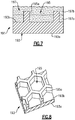
- Figure 2 illustrates an example gas turbine engine article 60 used in the engine 20.
- the article 60 is an airfoil, such as a turbine vane, as represented at 60a in Figure 1 , or a compressor vane, as represented at 60b in Figure 1 .
- the article 60 is a static vane.
- this disclosure is not limited to airfoils, and the examples may also be applicable to outer air seals or other turbine engine components that are exposed to high temperatures.
- the article 60 includes an end section 62 and an airfoil section 66 that spans in a longitudinal direction from the end section 62.
- the longitudinal direction is also the radial direction in the engine 20 with regard to the engine central axis A.
- the airfoil section 66 defines an airfoil profile (AP), which is the peripheral shape of the airfoil section 66 when viewed in a radial direction.
- the airfoil profile (AP) has a wing-like shape that provides a reaction force via Bernoulli's principle with regard to flow over the airfoil section 66.
- the full or complete airfoil profile (AP) generally includes a leading end (LE), a trailing end (TE), a pressure side (PS), and a suction side (SS).
- the leading end (LE) is the region of the airfoil profile (AP) that includes a leading edge of the airfoil profile (AP)
- the trailing end (TE) is the region of the airfoil profile that includes a trailing edge.
- the leading edge may be the portion of the airfoil profile (AP) that first contacts air or the foremost edge of the airfoil profile (AP).
- the trailing edge may be the portion of the airfoil profile (AP) that last contacts air or the aftmost edge of the airfoil profile (AP).
- the leading edge may shift, depending on the orientation of the vane.
- the article 60 may include another end section opposite the end section 62, with the airfoil section 66 spanning between the end sections.
- the airfoil section 66 is hollow and includes an interior cavity 68.
- the interior cavity 68 may be provided with cooling bleed air from the compressor section 24 of the engine 20, to cool the article 60.
- the airfoil section 66 includes at least a portion of a support structure 70 and a panel 72 that is attached with the support structure 70.
- the support structure 70 is an airfoil structure (hereafter airfoil structure 70) that may define a portion of the airfoil profile (AP).
- the airfoil structure 70 defines the leading end (LE), the pressure side (PS), and the trailing end (TE) of the airfoil profile (AP) and the panel 72 defines the suction side (SS), or at least a portion thereof.
- the support structure 70 will have a different geometry that mechanically supports the panel 72.
- the airfoil section 66 could include additional panels with features described herein. Additionally or alternatively, one or more of the panels could define one or more of the leading end (LE), the pressure side (PS), the trailing end (TE), or portions thereof.
- the panel 72 is in a seated position on the airfoil structure 70.
- the exterior surface of the panel 72 is flush or substantially flush with the exterior surface of the airfoil structure 70 to form a smooth airfoil profile (AP).
- the panel 72 includes perimeter edges 72a that fit with or engage edges 70a of the airfoil structure 70 when the panel 72 is in the seated position.
- the article 60 includes at least one preloaded compliant member 74 in the interior cavity 68.
- the preloaded compliant member 74 compliantly retains the panel 72 in the seated position on the airfoil structure 70. For instance, when at rest with no internal pressure in the interior cavity 68, the panel 72 would otherwise readily move, or could readily be moved, from the seated position in the absence of the preloaded compliant member 74. As will be appreciated, more than one preloaded compliant member 74 may be used to compliantly retain the panel 72 in the seated position.
- the preloaded compliant member 74 is "preloaded" in that a load applied displaces it from its at-rest position (position without any load applied).
- the load applied is from the force exerted on the preloaded compliant member 74 due to its position sandwiched between the airfoil structure 70 and the panel 72.
- the airfoil structure 70 and the panel 72 compress the preloaded compliant member 74.
- the compliant response of the preloaded compliant member 74 to the applied load is to exert an opposite force. This opposite force provides a positive force on the panel 72 against the airfoil structure 70 to keep the panel 72 in the seated position.
- the compliance that makes the member 74 "compliant” is the inverse of the stiffness of the preloaded compliant member 74.
- Stiffness (or inversely the compliance) may also be related to the elasticity, or elastic modulus, of the material used for the preloaded compliant member 74.
- the elastic modulus is not the same as the stiffness.
- Elastic modulus is a property of the material
- stiffness is a property of the component (the preloaded compliant member 74).
- the modulus is an intensive property of the material and the stiffness is an extensive property that relates to the material and shape of the component.
- Equations I and II below illustrate several examples of stiffness (and thus inversely compliance).
- k F / d where "k” is stiffness, “F” is force, and “d” is displacement.
- k A ⁇ E / L where “k” is stiffness, “A” is area, “E” is elastic modulus of the material, and “L” is length of the element.
- the airfoil structure 70 and the panel 72 may be formed of a ceramic or of a metal or a combination thereof.
- the panel 72 is ceramic and the airfoil structure 70 is metal.
- Metal alloys provide a good combination of strength and durability.
- Example alloys may include, but are not limited to, nickel alloys, cobalt alloys, a nickel alloy coated with cobalt or cobalt alloy, or non-nickel alloys that do not substantially react with ceramic.
- Ceramic may include, but is not limited to, oxides, carbides, nitrides, borides, silicides, and combinations thereof.
- a ceramic is a compound of metallic or metalloid elements bonded with nonmetallic elements or metalloid elements primarily in ionic or covalent bonds.
- the ceramic is a monolithic ceramic or a ceramic matrix composite (CMC).
- CMC ceramic matrix composite
- a monolithic ceramic is composed of a single, homogenous ceramic material.
- a composite is composed of two or more materials that are individually easily distinguishable.
- a CMC has a reinforcement phase, such as ceramic or carbon fibers, dispersed in a ceramic matrix formed of oxides, carbides, nitrides, borides, silicides, or combinations thereof.
- the preloaded compliant member 74 may also be formed of alloys, such as but not limited to, nickel alloys, cobalt alloys, a nickel alloy coated with cobalt or cobalt alloy, or non-nickel alloys that do not substantially react with ceramic.
- the airfoil structure 70 and/or the panel 72 may be coated with a thermal and/or environmental barrier ceramic coating, including but not limited to segmented coatings (discussed in further detail below with regard to Figures 6 and 7 ).
- the ceramic may include or may be oxides, carbides, nitrides, borides, silicides, or combinations thereof.
- the ceramic may be or may include yttria stabilized with zirconia, hafnia, and/or gadolinia, gadolinia zirconate, molybdate, alumina, or combinations thereof.
- the preloaded compliant member 74 When the article 60 heats up during engine operation, the preloaded compliant member 74 also heats up. However due to differences in the coefficients of thermal expansion between the airfoil structure 70 and the preloaded compliant member 74, the preloaded compliant member 74 will thermally expand at a greater rate than the airfoil structure 70 and thereby maintain the positive force on the panel 72.
- FIG 3A illustrates another example of selected portions of an article 160 in accordance with the invention
- Figure 3B illustrates a sectioned view of the article 160 (but without baffles) of Figure 3A
- like reference numerals designate like elements where appropriate and reference numerals with the addition of one-hundred or multiples thereof designate modified elements that are understood to incorporate the same features and benefits of the corresponding elements.
- the airfoil section 166 includes the airfoil structure 170 and the panel 172.
- the airfoil structure 170 is also shown in an isolated view in Figure 4 , without the panel 172.
- the perimeter edges 172a of the panel 172 include a perimeter bearing surface 80 and the edges 170a of the airfoil structure 170 include corresponding bearing surfaces 82.
- the bearing interface (I) is obliquely sloped, as represented at plane P, with respect to a line (L) that intersects the bearing interface (I) and that is orthogonal to an exterior surface (E1) of the airfoil structure 170 adjacent the bearing interface (I).
- the article 160 includes several different types of preloaded compliant members, represented at 174a and 174b.
- the preloaded compliant members 174a/174b compliantly retain the panel 172 in the seated position.
- both types of preloaded compliant members 174a/174b are shown in this example, further examples may include only the type of preloaded compliant member 174a or only the type of preloaded compliant member 174b.
- the article 160 may include additional panels 172, or the panel 172 may be divided into two or more panel pieces that are each held in a seated position by one or more preloaded compliant members 174a/174b.
- the preloaded compliant member 174a is a mechanical spring.
- the mechanical spring may be a leaf spring that includes two opposed leaves 174a-1 and 174a-2.
- the leaves 174a-1/174a-2 are pieces of curved or bent sheet metal that may be bonded together at the ends.
- the leaf spring may be a single piece of sheet metal that is curved or bent, or a flat piece of sheet metal.
- the leaf spring serves the as the preloaded compliant member to compliantly retain the panel 172 and also as a rib seal that divides the interior cavity 68.
- the airfoil structure 170 includes a first slot 84 and the panel 172 includes a second slot 86.
- the slots 84/86 may be in ribs that protrude from, respectively, the airfoil structure 170 and the panel 172.
- the rib seal (preloaded compliant member 174a) is retained by the slots 84/86 such that the rib seal cannot freely move laterally in the interior cavity 68.
- the rib seal may span the entire length, or substantially the entire length, of the interior cavity 68 such that the interior cavity 68 is divided into two isolated sub-cavities.
- a flat piece of sheet metal may be used as the preloaded compliant member 174a.
- the flat piece of sheet metal serves as a feather seal and may conform to the sides of the slots 84/86 due to a pressure differential across the sub-cavities.
- the interior cavity 68 could be divided into additional sub-cavities.
- the airfoil structure 170 and the panel 172 compress the preloaded compliant member 174a.
- the compliant response of the preloaded compliant member 174a to the applied load is to exert an opposite force.
- This opposite force provides a positive force on the panel 172, which is conveyed through the perimeter bearing surface 80 against the bearing surface 82 of the airfoil structure 170 to keep the panel 172 in the seated position.
- the preloaded compliant members 174b are baffles that are disposed in the interior cavity 68.
- the baffles include baffle walls 88.
- the baffle walls 88 circumscribe an interior baffle cavity 90.
- the baffle walls 88 may also include cooling holes 88a, for impingement cooling of the airfoil structure 170 and panel 172.
- Each baffle (preloaded compliant members 174b) is seated in the airfoil section 166 against spacers 92.
- the spacers 92 may be protrusions that are integrally formed with the airfoil structure 170, protrusions that are integrally formed with the panel 172, elements that are bonded to the airfoil structure 170, elements that are bonded to the panel 172, elements that are separate from the airfoil structure 170 and panel 172, or combinations thereof.
- the spacers 92 separate the baffles from the interior sides of the airfoil structure 170, the panel 172, or both such that there is a passage 94 there between. For instance, cooling bleed air is fed into the baffle cavities 90.
- the baffles discharge the bleed air through the cooling holes 88a to provide impingement flow onto the interior sides of the airfoil structure 170 and panel 172.
- the airfoil structure 170, the panel 172, or both may include outlet holes 96 to discharge the bleed air from the passage 94 into the core gas path.
- the airfoil structure 170 and the panel 172 compress the baffles (preloaded compliant members 174b).
- the compliant response of the preloaded compliant members 174b to the applied load is to exert an opposite force.
- This opposite force provides a positive force through the spacers 92 on the panel 172, which is conveyed through the perimeter bearing surface 80 against the bearing surface 82 of the airfoil structure 170 to keep the panel 172 in the seated position.
- the article 160 may be assembled by placing the panel 172 into the seated position in the interior cavity 68 of the airfoil structure 170, placing the compliant member (174a, 174b) in the interior cavity 68, and preloading the compliant member (174a, 174b) such that the preloaded compliant member (174a, 174b) compliantly retains the panel 172 in the seated position.
- Figure 5 illustrates another example article 260.
- the article 260 includes a plurality of panels 272 that form portions of the suction side (SS) of the airfoil section 266.
- the panels 272 are formed of ceramic, such as CMC or monolithic ceramic.
- the airfoil structure 270 includes a plurality of edges 272a that define bearing wedge portions 272b that have the bearing surfaces 80. The perimeter bearing surfaces 80 of the respective panels 272 contact the bearing surfaces 80 of the bearing wedge portions 272b in respective bearing interfaces (I).
- the airfoil structure 270 and the panels 272 compress the baffles (preloaded compliant members 174b).
- the compliant response of the preloaded compliant members 174b to the applied load is to exert an opposite force.
- This opposite force provides a positive force through the spacers 92 on the panels 272, which is conveyed through the perimeter bearing surfaces 80 against the bearing surfaces 82 of the airfoil structure 270 to keep the panels 272 in the seated positions.
- the member 174a serves only as a seal and does not retain any of the panels 272.
- Figures 6A, 6B , 6C, and 6D depict a further example of the method of assembly.
- Figure 6A depicts the airfoil structure 170 at the beginning of the method, without the panel 172 or preloaded compliant members 174a/174b.
- the panel 172 is placed into the interior cavity 68.
- the panel 172 may be inserted into the interior cavity 68 through the opening between the edges 170a or through one of the radial ends of the airfoil structure 170.
- the panel 172 is then moved into the seated position, such that the bearing surfaces 80/82 are brought into contact, or at least into close proximity of each other.
- the compliant member 174a is placed into the interior cavity 68 and preloaded by insertion into the slots 84/86. Insertion into the slots 84/86 may include deflecting (e.g., compressing) the compliant member 174a, placing it into the slots 84/86, and then releasing the compliant member 174a. Once released, since the space between the slots 84/86 is smaller than the size of the compliant member 174a in its at-rest position, the compliant member 174a is unable to spring back to its at-rest position, thereby preloading the compliant member 174a.
- the preloaded compliant members 174b may be assembled in a similar manner.
- the article 60/160/260 can be disassembled, the panel 72/172/272 can be replaced with a new one, and the article 60/160/260 can be reassembled. Accordingly, the panel 72/172/272 can be produced individually as a new article for original articles 60/160/260 or as an individual replacement article for an existing article or airfoil.
- the airfoil structure 70/170/270, the panel 72/172/272, or both may include a geometric segmented coating section.
- Figure 7 illustrates a representative geometric segmented coating section 191, which is also depicted in part in on the panel 172 ( Figure 3B ).
- the coating section 191 includes a metal wall 193.
- the metal wall 193 includes a first or inner side 193a and a second or exterior side 193b that is opposite the first side 193a.
- the second side 193b is also the exterior side that faces toward the core gas path.
- the second side 193b includes an array of cells 195 defined by cell sidewalls 195a.
- the array is a repeating geometric pattern of one or more cell geometries.
- the cell sidewalls 195a have a uniform thickness.
- the cells 195 are hexagonal.
- the cells 195 may be circular, ovular, other polygonal geometry, or mixed cell geometries.
- a coating 197 ( Figure 7 ) is disposed in the array of cells 195.
- the cells 195 mechanically facilitate bonding of the coating 197 on the wall 193.
- the cells 195 thus provide good bonding and spallation resistance of the coating 197, particularly at higher temperature locations. In turn, greater spallation resistance may reduce the need for bleed air for cooling or enable use of higher temperature bleed air that is less of an efficiency penalty.
- the coating 197 may be a barrier coating, such as a thermal barrier or environmental barrier, which is formed of a ceramic material.
- the coating 197 may be a monolayer coating but more typically will be a multi-layer coating.
- the coating 197 has a first coating layer 197a and a second coating layer 197b.
- the second coating layer 197b is a topcoat.
- the ceramic material of the coating 197 provides thermal and/or environmental resistance.
- the ceramic material may include or may be yttria stabilized with zirconia, hafnia, and/or gadolinia, gadolinia zirconate, molybdate, alumina, or combinations thereof.
- the ceramic material may include or may be a ceramic matrix composite which has a reinforcement phase, such as ceramic or carbon fibers, dispersed in a ceramic matrix formed of oxides, carbides, nitrides, borides, silicides, or combinations thereof.
- the coating 197 may also include a bond coat for attaching the ceramic material to the wall 193 and cells 195.
- the wall 193 and cells 195 may be formed of an alloy.
- Example alloys may include, but are not limited to, nickel alloys, cobalt alloys, a nickel alloy coated with cobalt or cobalt alloy, or a non-nickel alloys that do not substantially react with ceramic.
- the bond coat may include a nickel alloy, platinum, gold, silver, or MCrAlY, where the M includes at least one of nickel, cobalt, iron, or combinations thereof.
- the cell sidewalls 195a also facilitate reducing internal stresses in the coating 197 that may occur from sintering at relatively high surface temperatures during use in the engine 20.
- the sintering may result in partial melting, densification, and diffusional shrinkage of the coating 197 and thereby induce internal stresses.
- the cell sidewalls 195a serve to produce faults in at least the portion of the coating 197 above the cell sidewalls 195a.
- the faults provide locations for releasing energy associated with the internal stresses (e.g., reducing shear and radial stresses). That is, the energy associated with the internal stresses may be dissipated in the faults such that there is less energy available for causing delamination cracking between the coating 197 and the underlying wall 193.
- the coating section 191 may be formed using several different fabrication techniques.
- the wall 193 may be fabricated by investment casting, additive manufacturing, brazing, or combinations thereof, but is not limited to such techniques.
- the cells 195 can be separately fabricated and brazed to the remaining portion of the wall 193, which can be investment cast or additively fabricated.
- the cells 195 can be formed by other techniques, such as depositing an alloy coating and removing sections of the alloy coating by machining, electro-discharge machining (EDM), or other removal process.
- EDM electro-discharge machining
- the coating 197 ceramic coating material is deposited in the cells 195.
- the deposition process can include, but is not limited to, plasma spray or physical vapor deposition.
- plasma spray is used to produce a more durable version of the coating 197.
- the coating 197 has a laminar microstructure.
- the laminar microstructure includes grains of ceramic material that have a high aspect ratio.
- the laminar microstructure is a product of the plasma spray process, in which droplets of melted or partially melted ceramic material are sprayed onto the cells 195. Upon impact, the droplets flatten and solidify, yielding the laminar microstructure.
- the coating 197 has a porosity of less than 15%.
- the ceramic coating material fills or substantially fills the cells 195 and is deposited in a thickness that is greater than the height of the cell sidewalls 195a.
- the surface of the coating may have contours from the underlying cells 195. If such contours are undesired, the surface may be machined, ground, or abraded flat. For instance, the surface is reduced down to or close to the tops of the cell sidewalls 195a.
Landscapes
- Engineering & Computer Science (AREA)
- Mechanical Engineering (AREA)
- General Engineering & Computer Science (AREA)
- Chemical & Material Sciences (AREA)
- Materials Engineering (AREA)
- Ceramic Engineering (AREA)
- Architecture (AREA)
- Composite Materials (AREA)
- Combustion & Propulsion (AREA)
- Structures Of Non-Positive Displacement Pumps (AREA)
- Turbine Rotor Nozzle Sealing (AREA)
Description
- A gas turbine engine typically includes a fan section, a compressor section, a combustor section and a turbine section. Air entering the compressor section is compressed and delivered into the combustion section where it is mixed with fuel and ignited to generate a high-speed exhaust gas flow. The high-speed exhaust gas flow expands through the turbine section to drive the compressor and the fan section. The compressor section typically includes low and high pressure compressors, and the turbine section includes low and high pressure turbines.
- The high pressure turbine drives the high pressure compressor through an outer shaft to form a high spool, and the low pressure turbine drives the low pressure compressor through an inner shaft to form a low spool. The fan section may also be driven by the low inner shaft. A direct drive gas turbine engine includes a fan section driven by the low spool such that the low pressure compressor, low pressure turbine and fan section rotate at a common speed in a common direction.
- A speed reduction device, such as an epicyclical gear assembly, may be utilized to drive the fan section such that the fan section may rotate at a speed different than the turbine section. In such engine architectures, a shaft driven by one of the turbine sections provides an input to the epicyclical gear assembly that drives the fan section at a reduced speed.
-
US 5827045 A discloses a prior art airfoil according to the preamble ofclaim 1. - According to the present invention, there is provided an airfoil as set forth in
claim 1. - In an embodiment of the foregoing, the panel includes a perimeter bearing surface and the airfoil structure includes a bearing surface, and in the seated position the perimeter bearing surface and the bearing surface of the airfoil structure are in contact in a bearing interface.
- In a further embodiment of any of the foregoing embodiments, the bearing interface is obliquely sloped with respect to a line that intersects the bearing interface and that is orthogonal to an exterior surface of the airfoil structure adjacent the bearing interface.
- In a further embodiment of any of the foregoing embodiments, the preloaded compliant member includes a baffle.
- A further embodiment of any of the foregoing embodiments includes spacers between the baffle and the panel, the spacers separating the baffle from the panel such that there is a passage there between.
- In a further embodiment of any of the foregoing embodiments, the preloaded compliant member includes a mechanical spring and a baffle that is disposed in the interior cavity.
- In a further embodiment of any of the foregoing embodiments, the panel includes ceramic.
- In a further embodiment of any of the foregoing embodiments, the panel bounds a side of the interior cavity.
- In a further embodiment of any of the foregoing embodiments, the airfoil structure defines a different portion of the airfoil profile.
- There is further provided a gas turbine engine according to claim 9.
- There is further provided a method of assembling an airfoil according to claim 10.
- In an embodiment of the foregoing, the preloading includes deflecting the compliant member.
- In a further embodiment of any of the foregoing embodiments, the panel includes a perimeter bearing surface and the airfoil structure includes a bearing surface, and placing the panel into the seated position includes moving the perimeter bearing surface into contact in a bearing interface with the bearing surface of the airfoil structure.
- In a further embodiment of any of the foregoing embodiments, the bearing interface is obliquely sloped with respect to a line that intersects the bearing interface and that is orthogonal to an exterior surface of the airfoil structure adjacent the bearing interface.
- There is further provided a gas turbine engine article according to claim 14.
- In an embodiment of the foregoing, the bearing interface is obliquely sloped with respect to a line that intersects the bearing interface and that is orthogonal to an exterior surface of the support structure adjacent the bearing interface.
- The various features and advantages of the present disclosure will become apparent to those skilled in the art from the following detailed description. The drawings that accompany the detailed description can be briefly described as follows.
-
Figure 1 illustrates an example gas turbine engine. -
Figure 2 illustrates an example article of the engine ofFigure 1 . In the example shown, the article is an airfoil. -
Figure 3A illustrates an article in accordance with the invention. -
Figure 3B illustrates a sectioned view of the article ofFigure 3A . -
Figure 4 illustrates an isolated view of an airfoil structure of the airfoil ofFigure 3A . -
Figure 5 illustrates another example article with a plurality of panels. -
Figures 6A, 6B ,6C, and 6D depict a method of assembling an airfoil in accordance with the invention. -
Figure 7 illustrates a representative portion of a geometrically segmented coating section. -
Figure 8 illustrates an isolated view of a wall of the coating section ofFigure 6 . -
Figure 1 schematically illustrates agas turbine engine 20. Thegas turbine engine 20 is disclosed herein as a two-spool turbofan that generally incorporates afan section 22, a compressor section 24, acombustor section 26 and aturbine section 28. Alternative engine designs can include an augmentor section (not shown) among other systems or features. - The
fan section 22 drives air along a bypass flow path B in a bypass duct defined within anacelle 15, while the compressor section 24 drives air along a core flow path C for compression and communication into thecombustor section 26 then expansion through theturbine section 28. Although depicted as a two-spool turbofan gas turbine engine in the disclosed non-limiting embodiment, the examples herein are not limited to use with two-spool turbofans and may be applied to other types of turbomachinery, including direct drive engine architectures, three-spool engine architectures, and ground-based turbines. - The
engine 20 generally includes alow speed spool 30 and ahigh speed spool 32 mounted for rotation about an engine central longitudinal axis A relative to an engine static structure 36 viaseveral bearing systems 38. It should be understood thatvarious bearing systems 38 at various locations may alternatively or additionally be provided, and the location ofbearing systems 38 may be varied as appropriate to the application. - The
low speed spool 30 generally includes aninner shaft 40 that interconnects afan 42, a first (or low)pressure compressor 44 and a first (or low)pressure turbine 46. Theinner shaft 40 may be connected to thefan 42 through a speed change mechanism, which in exemplarygas turbine engine 20 is illustrated as a gearedarchitecture 48, to drive thefan 42 at a lower speed than thelow speed spool 30. - The
high speed spool 32 includes anouter shaft 50 that interconnects a second (or high)pressure compressor 52 and a second (or high)pressure turbine 54. Acombustor 56 is arranged between thehigh pressure compressor 52 and thehigh pressure turbine 54. Amid-turbine frame 57 of the engine static structure 36, if included, is arranged generally between thehigh pressure turbine 54 and thelow pressure turbine 46. Themid-turbine frame 57 further supports thebearing systems 38 in theturbine section 28. Theinner shaft 40 and theouter shaft 50 are concentric and rotate viabearing systems 38 about the engine central longitudinal axis A, which is collinear with their longitudinal axes. - The core airflow is compressed by the
low pressure compressor 44 then thehigh pressure compressor 52, mixed and burned with fuel in thecombustor 56, then expanded through thehigh pressure turbine 54 andlow pressure turbine 46. Themid-turbine frame 57 includesairfoils 59 which are in the core airflow path C. Theturbines low speed spool 30 andhigh speed spool 32 in response to the expansion. It will be appreciated that each of the positions of thefan section 22, compressor section 24,combustor section 26,turbine section 28, and fandrive gear system 48 may be varied. For example,gear system 48 may be located aft ofcombustor section 26 or even aft ofturbine section 28, andfan section 22 may be positioned forward or aft of the location ofgear system 48. - The
engine 20 in one example is a high-bypass geared aircraft engine. In a further example, theengine 20 bypass ratio is greater than about six, with an example embodiment being greater than about ten, the gearedarchitecture 48 is an epicyclic gear train, such as a planetary gear system or other gear system, with a gear reduction ratio of greater than about 2.3 and thelow pressure turbine 46 has a pressure ratio that is greater than about five. In one disclosed embodiment, theengine 20 bypass ratio is greater than about ten, the fan diameter is significantly larger than that of thelow pressure compressor 44, and thelow pressure turbine 46 has a pressure ratio that is greater than about five.Low pressure turbine 46 pressure ratio is pressure measured prior to inlet oflow pressure turbine 46 as related to the pressure at the outlet of thelow pressure turbine 46 prior to an exhaust nozzle. The gearedarchitecture 48 may be an epicycle gear train, such as a planetary gear system or other gear system, with a gear reduction ratio of greater than about 2.3:1. It should be understood, however, that the above parameters are only exemplary of one embodiment of a geared architecture engine and that the present invention is applicable to other gas turbine engines, including direct drive turbofans and gas turbines with multiple bypass streams. - A significant amount of thrust is provided by the bypass flow B due to the high bypass ratio. The
fan section 22 of theengine 20 may be designed for a particular flight condition -- typically cruise at about 0.8 Mach and about 10,668 m (35,000 feet). The flight condition of 0.8 Mach and 10,668 m (35,000 feet), with the engine at its best fuel consumption - also known as "bucket cruise Thrust Specific Fuel Consumption ('TSFC')" - is the industry standard parameter of lbm of fuel being burned divided by lbf of thrust the engine produces at that minimum point. "Low fan pressure ratio" is the pressure ratio across the fan blade alone, without a Fan Exit Guide Vane ("FEGV") system. The low fan pressure ratio as disclosed herein according to one non-limiting embodiment is less than about 1.45. "Low corrected fan tip speed" is the actual fan tip speed in ft/sec divided by an industry standard temperature correction of [(Tram °R) / (518.7 R)]0.5 (where °R = K x 9/5). The "Low corrected fan tip speed" as disclosed herein according to one non-limiting embodiment is less than about 350.5 m/s (1150 ft/second). - In gas turbine engines air is often bled from the compressor for cooling components in the turbine that cannot withstand stoichiometric ideal temperatures of fuel burn; however, compressor bleed penalizes engine efficiency. Efficiency is governed by thermodynamics and mass flow through the turbine. Efficiency can generally be increased by lowering volume of compressor bleed, increasing velocity of compressor bleed, or increasing temperature of compressor bleed. These goals are challenging to meet because compressor bleed relies on the pressure differential between the compressor and the turbine. That is, the goals of lower volume, increased velocity, and increased temperature of compressor bleed are generally opposite to the goals of high pressure and low temperature compressor bleed desired for achieving good pressure differential. In this regard, to facilitate overcoming such challenges, an approach taken in this disclosure is to reduce the need for compressor bleed and cooling by enhancing the temperature resistance capability of the turbine or other components exposed to high temperatures. In particular, thermal resistance can be enhanced at the compressor exit and turbine inlet.
-
Figure 2 illustrates an example gasturbine engine article 60 used in theengine 20. In the illustrated example thearticle 60 is an airfoil, such as a turbine vane, as represented at 60a inFigure 1 , or a compressor vane, as represented at 60b inFigure 1 . In this example, thearticle 60 is a static vane. As will be appreciated, although the examples herein are described in the context of an airfoil, this disclosure is not limited to airfoils, and the examples may also be applicable to outer air seals or other turbine engine components that are exposed to high temperatures. - In this example, the
article 60 includes anend section 62 and anairfoil section 66 that spans in a longitudinal direction from theend section 62. The longitudinal direction is also the radial direction in theengine 20 with regard to the engine central axis A. Theairfoil section 66 defines an airfoil profile (AP), which is the peripheral shape of theairfoil section 66 when viewed in a radial direction. For example, the airfoil profile (AP) has a wing-like shape that provides a reaction force via Bernoulli's principle with regard to flow over theairfoil section 66. The full or complete airfoil profile (AP) generally includes a leading end (LE), a trailing end (TE), a pressure side (PS), and a suction side (SS). For example, the leading end (LE) is the region of the airfoil profile (AP) that includes a leading edge of the airfoil profile (AP), and the trailing end (TE) is the region of the airfoil profile that includes a trailing edge. The leading edge may be the portion of the airfoil profile (AP) that first contacts air or the foremost edge of the airfoil profile (AP). The trailing edge may be the portion of the airfoil profile (AP) that last contacts air or the aftmost edge of the airfoil profile (AP). For a variable vane, the leading edge may shift, depending on the orientation of the vane. As will be appreciated, thearticle 60 may include another end section opposite theend section 62, with theairfoil section 66 spanning between the end sections. - The
airfoil section 66 is hollow and includes aninterior cavity 68. Theinterior cavity 68 may be provided with cooling bleed air from the compressor section 24 of theengine 20, to cool thearticle 60. - The
airfoil section 66 includes at least a portion of asupport structure 70 and apanel 72 that is attached with thesupport structure 70. In the example of an airfoil, thesupport structure 70 is an airfoil structure (hereafter airfoil structure 70) that may define a portion of the airfoil profile (AP). In this example, theairfoil structure 70 defines the leading end (LE), the pressure side (PS), and the trailing end (TE) of the airfoil profile (AP) and thepanel 72 defines the suction side (SS), or at least a portion thereof. For a blade outer air seal or other turbine engine article, thesupport structure 70 will have a different geometry that mechanically supports thepanel 72. As will be appreciated, although the illustrated example includes only onepanel 72, theairfoil section 66 could include additional panels with features described herein. Additionally or alternatively, one or more of the panels could define one or more of the leading end (LE), the pressure side (PS), the trailing end (TE), or portions thereof. - The
panel 72 is in a seated position on theairfoil structure 70. For example, in the seated position the exterior surface of thepanel 72 is flush or substantially flush with the exterior surface of theairfoil structure 70 to form a smooth airfoil profile (AP). In another example, thepanel 72 includes perimeter edges 72a that fit with or engageedges 70a of theairfoil structure 70 when thepanel 72 is in the seated position. - The
article 60 includes at least one preloadedcompliant member 74 in theinterior cavity 68. The preloadedcompliant member 74 compliantly retains thepanel 72 in the seated position on theairfoil structure 70. For instance, when at rest with no internal pressure in theinterior cavity 68, thepanel 72 would otherwise readily move, or could readily be moved, from the seated position in the absence of the preloadedcompliant member 74. As will be appreciated, more than one preloadedcompliant member 74 may be used to compliantly retain thepanel 72 in the seated position. - The preloaded
compliant member 74 is "preloaded" in that a load applied displaces it from its at-rest position (position without any load applied). As an example, the load applied is from the force exerted on the preloadedcompliant member 74 due to its position sandwiched between theairfoil structure 70 and thepanel 72. For instance, theairfoil structure 70 and thepanel 72 compress the preloadedcompliant member 74. In this regard, the compliant response of the preloadedcompliant member 74 to the applied load is to exert an opposite force. This opposite force provides a positive force on thepanel 72 against theairfoil structure 70 to keep thepanel 72 in the seated position. - As an example, the compliance that makes the
member 74 "compliant" is the inverse of the stiffness of the preloadedcompliant member 74. Stiffness (or inversely the compliance) may also be related to the elasticity, or elastic modulus, of the material used for the preloadedcompliant member 74. However, the elastic modulus is not the same as the stiffness. Elastic modulus is a property of the material, and stiffness is a property of the component (the preloaded compliant member 74). Thus, the modulus is an intensive property of the material and the stiffness is an extensive property that relates to the material and shape of the component. As will be appreciated, there are known ways of expressing stiffness, and thus compliance. Although not limited, Equations I and II below illustrate several examples of stiffness (and thus inversely compliance).

- The materials of which the
article 60 is formed of may be selected to enhance the performance. For example, theairfoil structure 70 and thepanel 72 may be formed of a ceramic or of a metal or a combination thereof. For instance, thepanel 72 is ceramic and theairfoil structure 70 is metal. Metal alloys provide a good combination of strength and durability. Example alloys may include, but are not limited to, nickel alloys, cobalt alloys, a nickel alloy coated with cobalt or cobalt alloy, or non-nickel alloys that do not substantially react with ceramic. Ceramic may include, but is not limited to, oxides, carbides, nitrides, borides, silicides, and combinations thereof. A ceramic is a compound of metallic or metalloid elements bonded with nonmetallic elements or metalloid elements primarily in ionic or covalent bonds. In further examples, the ceramic is a monolithic ceramic or a ceramic matrix composite (CMC). For example, a monolithic ceramic is composed of a single, homogenous ceramic material. In comparison, a composite is composed of two or more materials that are individually easily distinguishable. A CMC has a reinforcement phase, such as ceramic or carbon fibers, dispersed in a ceramic matrix formed of oxides, carbides, nitrides, borides, silicides, or combinations thereof. The preloadedcompliant member 74 may also be formed of alloys, such as but not limited to, nickel alloys, cobalt alloys, a nickel alloy coated with cobalt or cobalt alloy, or non-nickel alloys that do not substantially react with ceramic. - If enhanced thermal or environmental resistance is desired, the
airfoil structure 70 and/or thepanel 72 may be coated with a thermal and/or environmental barrier ceramic coating, including but not limited to segmented coatings (discussed in further detail below with regard toFigures 6 and7 ). As an example, the ceramic may include or may be oxides, carbides, nitrides, borides, silicides, or combinations thereof. In further examples, the ceramic may be or may include yttria stabilized with zirconia, hafnia, and/or gadolinia, gadolinia zirconate, molybdate, alumina, or combinations thereof. - When the
article 60 heats up during engine operation, the preloadedcompliant member 74 also heats up. However due to differences in the coefficients of thermal expansion between theairfoil structure 70 and the preloadedcompliant member 74, the preloadedcompliant member 74 will thermally expand at a greater rate than theairfoil structure 70 and thereby maintain the positive force on thepanel 72. -
Figure 3A illustrates another example of selected portions of anarticle 160 in accordance with the invention, andFigure 3B illustrates a sectioned view of the article 160 (but without baffles) ofFigure 3A . In this disclosure, like reference numerals designate like elements where appropriate and reference numerals with the addition of one-hundred or multiples thereof designate modified elements that are understood to incorporate the same features and benefits of the corresponding elements. Theairfoil section 166 includes theairfoil structure 170 and thepanel 172. Theairfoil structure 170 is also shown in an isolated view inFigure 4 , without thepanel 172. The perimeter edges 172a of thepanel 172 include aperimeter bearing surface 80 and theedges 170a of theairfoil structure 170 include corresponding bearing surfaces 82. - In the seated position, the
perimeter bearing surface 80 contacts the bearingsurface 82 in a bearing interface (I). The bearing surfaces 80/82 are sloped such that thepanel 172 self-centers on theairfoil structure 170. As an example, the bearing interface (I) is obliquely sloped, as represented at plane P, with respect to a line (L) that intersects the bearing interface (I) and that is orthogonal to an exterior surface (E1) of theairfoil structure 170 adjacent the bearing interface (I). - In the illustrated example, the
article 160 includes several different types of preloaded compliant members, represented at 174a and 174b. The preloadedcompliant members 174a/174b compliantly retain thepanel 172 in the seated position. As will be appreciated, although both types of preloadedcompliant members 174a/174b are shown in this example, further examples may include only the type of preloadedcompliant member 174a or only the type of preloadedcompliant member 174b. Further, thearticle 160 may includeadditional panels 172, or thepanel 172 may be divided into two or more panel pieces that are each held in a seated position by one or more preloadedcompliant members 174a/174b. - The preloaded
compliant member 174a is a mechanical spring. As shown, the mechanical spring may be a leaf spring that includes twoopposed leaves 174a-1 and 174a-2. For instance, theleaves 174a-1/174a-2 are pieces of curved or bent sheet metal that may be bonded together at the ends. Alternatively, the leaf spring may be a single piece of sheet metal that is curved or bent, or a flat piece of sheet metal. - It is to be understood that other types of mechanical springs could alternatively be used. In this example though, the leaf spring serves the as the preloaded compliant member to compliantly retain the
panel 172 and also as a rib seal that divides theinterior cavity 68. Theairfoil structure 170 includes afirst slot 84 and thepanel 172 includes asecond slot 86. Theslots 84/86 may be in ribs that protrude from, respectively, theairfoil structure 170 and thepanel 172. The rib seal (preloadedcompliant member 174a) is retained by theslots 84/86 such that the rib seal cannot freely move laterally in theinterior cavity 68. Moreover, the rib seal may span the entire length, or substantially the entire length, of theinterior cavity 68 such that theinterior cavity 68 is divided into two isolated sub-cavities. For enhanced sealing, a flat piece of sheet metal may be used as the preloadedcompliant member 174a. The flat piece of sheet metal serves as a feather seal and may conform to the sides of theslots 84/86 due to a pressure differential across the sub-cavities. Of course, if more than one rib seal were used, theinterior cavity 68 could be divided into additional sub-cavities. - Similar to the
article 60, theairfoil structure 170 and thepanel 172 compress the preloadedcompliant member 174a. In this regard, the compliant response of the preloadedcompliant member 174a to the applied load is to exert an opposite force. This opposite force provides a positive force on thepanel 172, which is conveyed through theperimeter bearing surface 80 against the bearingsurface 82 of theairfoil structure 170 to keep thepanel 172 in the seated position. - The preloaded
compliant members 174b (two shown) are baffles that are disposed in theinterior cavity 68. For example the baffles includebaffle walls 88. In this example, thebaffle walls 88 circumscribe aninterior baffle cavity 90. Thebaffle walls 88 may also includecooling holes 88a, for impingement cooling of theairfoil structure 170 andpanel 172. - Each baffle (preloaded
compliant members 174b) is seated in theairfoil section 166 againstspacers 92. As examples, thespacers 92 may be protrusions that are integrally formed with theairfoil structure 170, protrusions that are integrally formed with thepanel 172, elements that are bonded to theairfoil structure 170, elements that are bonded to thepanel 172, elements that are separate from theairfoil structure 170 andpanel 172, or combinations thereof. Thespacers 92 separate the baffles from the interior sides of theairfoil structure 170, thepanel 172, or both such that there is apassage 94 there between. For instance, cooling bleed air is fed into thebaffle cavities 90. The baffles discharge the bleed air through thecooling holes 88a to provide impingement flow onto the interior sides of theairfoil structure 170 andpanel 172. Theairfoil structure 170, thepanel 172, or both may include outlet holes 96 to discharge the bleed air from thepassage 94 into the core gas path. - Similar to the preloaded
compliant member 174a, theairfoil structure 170 and thepanel 172 compress the baffles (preloadedcompliant members 174b). In this regard, the compliant response of the preloadedcompliant members 174b to the applied load is to exert an opposite force. This opposite force provides a positive force through thespacers 92 on thepanel 172, which is conveyed through theperimeter bearing surface 80 against the bearingsurface 82 of theairfoil structure 170 to keep thepanel 172 in the seated position. - The
article 160 may be assembled by placing thepanel 172 into the seated position in theinterior cavity 68 of theairfoil structure 170, placing the compliant member (174a, 174b) in theinterior cavity 68, and preloading the compliant member (174a, 174b) such that the preloaded compliant member (174a, 174b) compliantly retains thepanel 172 in the seated position. -
Figure 5 illustrates anotherexample article 260. In this example, rather than thesingle panel 172, thearticle 260 includes a plurality ofpanels 272 that form portions of the suction side (SS) of theairfoil section 266. For example, thepanels 272 are formed of ceramic, such as CMC or monolithic ceramic. Theairfoil structure 270 includes a plurality ofedges 272a that define bearingwedge portions 272b that have the bearing surfaces 80. The perimeter bearing surfaces 80 of therespective panels 272 contact the bearing surfaces 80 of the bearingwedge portions 272b in respective bearing interfaces (I). - Similar to the
article 160, theairfoil structure 270 and thepanels 272 compress the baffles (preloadedcompliant members 174b). In this regard, the compliant response of the preloadedcompliant members 174b to the applied load is to exert an opposite force. This opposite force provides a positive force through thespacers 92 on thepanels 272, which is conveyed through the perimeter bearing surfaces 80 against the bearing surfaces 82 of theairfoil structure 270 to keep thepanels 272 in the seated positions. In this example, themember 174a serves only as a seal and does not retain any of thepanels 272. -
Figures 6A, 6B ,6C, and 6D depict a further example of the method of assembly.Figure 6A depicts theairfoil structure 170 at the beginning of the method, without thepanel 172 or preloadedcompliant members 174a/174b. InFigure 6B , thepanel 172 is placed into theinterior cavity 68. For instance, thepanel 172 may be inserted into theinterior cavity 68 through the opening between theedges 170a or through one of the radial ends of theairfoil structure 170. As shown inFigure 6C , thepanel 172 is then moved into the seated position, such that the bearing surfaces 80/82 are brought into contact, or at least into close proximity of each other. As depicted inFigure 6D , thecompliant member 174a is placed into theinterior cavity 68 and preloaded by insertion into theslots 84/86. Insertion into theslots 84/86 may include deflecting (e.g., compressing) thecompliant member 174a, placing it into theslots 84/86, and then releasing thecompliant member 174a. Once released, since the space between theslots 84/86 is smaller than the size of thecompliant member 174a in its at-rest position, thecompliant member 174a is unable to spring back to its at-rest position, thereby preloading thecompliant member 174a. The preloadedcompliant members 174b may be assembled in a similar manner. - Should the
panel 72/172/272 require replacement, thearticle 60/160/260 can be disassembled, thepanel 72/172/272 can be replaced with a new one, and thearticle 60/160/260 can be reassembled. Accordingly, thepanel 72/172/272 can be produced individually as a new article fororiginal articles 60/160/260 or as an individual replacement article for an existing article or airfoil. - Additionally or alternatively, the
airfoil structure 70/170/270, thepanel 72/172/272, or both may include a geometric segmented coating section. For instance,Figure 7 illustrates a representative geometricsegmented coating section 191, which is also depicted in part in on the panel 172 (Figure 3B ). Thecoating section 191 includes ametal wall 193. Themetal wall 193 includes a first orinner side 193a and a second orexterior side 193b that is opposite thefirst side 193a. Thesecond side 193b is also the exterior side that faces toward the core gas path. Thesecond side 193b includes an array ofcells 195 defined bycell sidewalls 195a. The array is a repeating geometric pattern of one or more cell geometries. In this example, thecell sidewalls 195a have a uniform thickness. As shown in the isolated view of thewall 193 inFigure 8 , thecells 195 are hexagonal. Alternatively, thecells 195 may be circular, ovular, other polygonal geometry, or mixed cell geometries. - A coating 197 (
Figure 7 ) is disposed in the array ofcells 195. Thecells 195 mechanically facilitate bonding of thecoating 197 on thewall 193. Thecells 195 thus provide good bonding and spallation resistance of thecoating 197, particularly at higher temperature locations. In turn, greater spallation resistance may reduce the need for bleed air for cooling or enable use of higher temperature bleed air that is less of an efficiency penalty. Thecoating 197 may be a barrier coating, such as a thermal barrier or environmental barrier, which is formed of a ceramic material. Thecoating 197 may be a monolayer coating but more typically will be a multi-layer coating. For instance, thecoating 197 has afirst coating layer 197a and asecond coating layer 197b. In this example, thesecond coating layer 197b is a topcoat. - The ceramic material of the
coating 197 provides thermal and/or environmental resistance. As an example, the ceramic material may include or may be yttria stabilized with zirconia, hafnia, and/or gadolinia, gadolinia zirconate, molybdate, alumina, or combinations thereof. Additionally or alternatively, the ceramic material may include or may be a ceramic matrix composite which has a reinforcement phase, such as ceramic or carbon fibers, dispersed in a ceramic matrix formed of oxides, carbides, nitrides, borides, silicides, or combinations thereof. - The
coating 197 may also include a bond coat for attaching the ceramic material to thewall 193 andcells 195. Thewall 193 andcells 195 may be formed of an alloy. Example alloys may include, but are not limited to, nickel alloys, cobalt alloys, a nickel alloy coated with cobalt or cobalt alloy, or a non-nickel alloys that do not substantially react with ceramic. The bond coat may include a nickel alloy, platinum, gold, silver, or MCrAlY, where the M includes at least one of nickel, cobalt, iron, or combinations thereof. - The
cell sidewalls 195a also facilitate reducing internal stresses in thecoating 197 that may occur from sintering at relatively high surface temperatures during use in theengine 20. The sintering may result in partial melting, densification, and diffusional shrinkage of thecoating 197 and thereby induce internal stresses. Thecell sidewalls 195a serve to produce faults in at least the portion of thecoating 197 above thecell sidewalls 195a. The faults provide locations for releasing energy associated with the internal stresses (e.g., reducing shear and radial stresses). That is, the energy associated with the internal stresses may be dissipated in the faults such that there is less energy available for causing delamination cracking between thecoating 197 and theunderlying wall 193. - The
coating section 191 may be formed using several different fabrication techniques. As an example, thewall 193 may be fabricated by investment casting, additive manufacturing, brazing, or combinations thereof, but is not limited to such techniques. For instance, thecells 195 can be separately fabricated and brazed to the remaining portion of thewall 193, which can be investment cast or additively fabricated. Alternatively, thecells 195 can be formed by other techniques, such as depositing an alloy coating and removing sections of the alloy coating by machining, electro-discharge machining (EDM), or other removal process. - To produce the
coating 197, ceramic coating material is deposited in thecells 195. The deposition process can include, but is not limited to, plasma spray or physical vapor deposition. In one example, plasma spray is used to produce a more durable version of thecoating 197. For instance, thecoating 197 has a laminar microstructure. The laminar microstructure includes grains of ceramic material that have a high aspect ratio. The laminar microstructure is a product of the plasma spray process, in which droplets of melted or partially melted ceramic material are sprayed onto thecells 195. Upon impact, the droplets flatten and solidify, yielding the laminar microstructure. There may be voids or pores among the grains; however, thecoating 197 is substantially fully dense. For instance, thecoating 197 has a porosity of less than 15%. - The ceramic coating material fills or substantially fills the
cells 195 and is deposited in a thickness that is greater than the height of thecell sidewalls 195a. At this stage, the surface of the coating may have contours from theunderlying cells 195. If such contours are undesired, the surface may be machined, ground, or abraded flat. For instance, the surface is reduced down to or close to the tops of thecell sidewalls 195a. - Although a combination of features is shown in the illustrated examples, not all of them need to be combined to realize the benefits of various embodiments of this disclosure. In other words, a system designed according to an embodiment of this disclosure will not necessarily include all of the features shown in any one of the Figures or all of the portions schematically shown in the Figures. Moreover, selected features of one example embodiment may be combined with selected features of other example embodiments.
- The preceding description is exemplary rather than limiting in nature. Variations and modifications to the disclosed examples may become apparent to those skilled in the art that do not necessarily depart from this disclosure. The scope of legal protection given to this disclosure can only be determined by studying the following claims.
Claims (15)
- An airfoil (160; 260) comprising:an airfoil structure (170; 270) having an interior cavity (68);a preloaded compliant member (174a, 174b) in the interior cavity (68); anda panel (172; 272) defining a portion of an airfoil profile (AP), the preloaded compliant member (174a) compliantly retaining the panel (172; 272) in a seated position on the airfoil structure (170; 270), wherein the preloaded compliant member (174a) includes a mechanical spring (174a),characterised in that:
the mechanical spring (174a) is a rib seal (174a) that divides the interior cavity (68), the airfoil structure (170; 270) includes a first slot (84), the panel (172; 272) includes a second slot (86), and the first slot (84) and the second slot (86) retain the rib seal (174a). - The airfoil (160; 260) as recited in claim 1, wherein the panel (172; 272) includes a perimeter bearing surface (80) and the airfoil structure (170; 270) includes a bearing surface (82), and in the seated position the perimeter bearing surface (80) and the bearing surface (82) of the airfoil structure (170; 270) are in contact in a bearing interface (I).
- The airfoil (160; 260) as recited in claim 2, wherein the bearing interface (I) is obliquely sloped with respect to a line (L) that intersects the bearing interface (I) and that is orthogonal to an exterior surface (E1) of the airfoil structure (170; 270) adjacent the bearing interface (I).
- The airfoil (160; 260) as recited in any preceding claim, wherein the preloaded compliant member (174a) includes a baffle (174b), the baffle (174b) optionally being disposed in the interior cavity (68).
- The airfoil (160; 260) as recited in claim 4, further comprising spacers (92) between the baffle (174b) and the panel (172; 272), the spacers (92) separating the baffle (174b) from the panel (172; 272) such that there is a passage (94) therebetween.
- The airfoil (160; 260) as recited in any preceding claim, wherein the panel (172; 272) includes ceramic.
- The airfoil (160; 260) as recited in any preceding claim, wherein the panel (172; 272) bounds a side of the interior cavity (68).
- The airfoil (160; 260) as recited in any preceding claim, wherein the airfoil structure (170; 270) defines a different portion of the airfoil profile (AP).
- A gas turbine engine (20) comprising:a compressor section (24);a combustor (56) in fluid communication with the compressor section (24); anda turbine section (28) in fluid communication with the combustor (56), at least one of the turbine section (28) or the compressor section (24) including the airfoil (160; 260) of any preceding claim.
- A method of assembling an airfoil (160; 260), the method comprising:placing a panel (172; 272) into a seated position in an interior cavity (68) of an airfoil structure (170; 270); andplacing a compliant member (174a) in the interior cavity (68) and preloading the compliant member (174a) such that the preloaded compliant member (174a) compliantly retains the panel (172; 272) in the seated position, wherein the preloaded compliant member (174a) includes a mechanical spring (174a),characterised in that:
the mechanical spring (174a) is a rib seal (174a) that divides the interior cavity (68), the airfoil structure (170; 270) includes a first slot (84), the panel (172; 272) includes a second slot (86), and the first slot (84) and the second slot (86) retain the rib seal (174a). - The method as recited in claim 10, wherein the preloading includes deflecting the compliant member (174a).
- The method as recited in claim 10 or 11, wherein the panel (172; 272) includes a perimeter bearing surface (80) and the airfoil structure (170; 270) includes a bearing surface (82), and placing the panel (172; 272) into the seated position includes moving the perimeter bearing surface (80) into contact in a bearing interface (I) with the bearing surface (82) of the airfoil structure (170; 270).
- The method as recited in claim 12, wherein the bearing interface (I) is obliquely sloped with respect to a line (L) that intersects the bearing interface (I) and that is orthogonal to an exterior surface (E1) of the airfoil structure (170; 270) adjacent the bearing interface (I).
- A gas turbine engine article (160; 260) comprising:a support structure (170; 270) having an interior cavity (68) and a bearing surface (82);a preloaded compliant member (174a) in the interior cavity (68); anda panel (172; 272) having a core gas path side and a perimeter bearing surface (80), and in a seated position of the panel (172; 272) on the support structure (170; 270) the preloaded compliant member (174a) compliantly retaining the perimeter bearing surface (80) of the panel (172; 272) in contact against the bearing surface (82) of the support structure (170; 270) in a bearing interface (I), wherein the preloaded compliant member (174a) includes a mechanical spring (174a),characterised in that:
the mechanical spring (174a) is a rib seal (174a) that divides the interior cavity (68), the support structure (170; 270) includes a first slot (84), the panel (172; 272) includes a second slot (86), and the first slot (84) and the second slot (86) retain the rib seal (174a). - The article (160; 260) as recited in claim 14, wherein the bearing interface (I) is obliquely sloped with respect to a line (L) that intersects the bearing interface (I) and that is orthogonal to an exterior surface (E1) of the support structure (170; 270) adjacent the bearing interface (I).
Applications Claiming Priority (1)
| Application Number | Priority Date | Filing Date | Title |
|---|---|---|---|
| US15/354,373 US10408090B2 (en) | 2016-11-17 | 2016-11-17 | Gas turbine engine article with panel retained by preloaded compliant member |
Publications (2)
| Publication Number | Publication Date |
|---|---|
| EP3323985A1 EP3323985A1 (en) | 2018-05-23 |
| EP3323985B1 true EP3323985B1 (en) | 2019-06-26 |
Family
ID=60387934
Family Applications (1)
| Application Number | Title | Priority Date | Filing Date |
|---|---|---|---|
| EP17202364.0A Active EP3323985B1 (en) | 2016-11-17 | 2017-11-17 | Airfoil, gas turbine engine article, corresponding gas turbine engine and method of assembling an airfoil |
Country Status (2)
| Country | Link |
|---|---|
| US (1) | US10408090B2 (en) |
| EP (1) | EP3323985B1 (en) |
Families Citing this family (10)
| Publication number | Priority date | Publication date | Assignee | Title |
|---|---|---|---|---|
| US10662779B2 (en) * | 2016-11-17 | 2020-05-26 | Raytheon Technologies Corporation | Gas turbine engine component with degradation cooling scheme |
| CN109057872B (en) * | 2018-08-01 | 2021-01-05 | 常州金坛环保设备有限公司 | Steam turbine blade |
| US10934868B2 (en) * | 2018-09-12 | 2021-03-02 | Rolls-Royce North American Technologies Inc. | Turbine vane assembly with variable position support |
| US11377964B2 (en) * | 2018-11-09 | 2022-07-05 | Raytheon Technologies Corporation | Airfoil with cooling passage network having arced leading edge |
| KR102116504B1 (en) * | 2018-12-03 | 2020-05-28 | 두산중공업 주식회사 | Vane, method for manufacturing vane, and gas turbine |
| US10975709B1 (en) | 2019-11-11 | 2021-04-13 | Rolls-Royce Plc | Turbine vane assembly with ceramic matrix composite components and sliding support |
| US11085374B2 (en) * | 2019-12-03 | 2021-08-10 | General Electric Company | Impingement insert with spring element for hot gas path component |
| US11203981B1 (en) | 2020-08-06 | 2021-12-21 | Raytheon Technologies Corporation | Baffle systems for airfoils |
| US11415006B2 (en) * | 2020-09-17 | 2022-08-16 | Raytheon Technologies Corporation | CMC vane with support spar and baffle |
| US11519280B1 (en) | 2021-09-30 | 2022-12-06 | Rolls-Royce Plc | Ceramic matrix composite vane assembly with compliance features |
Family Cites Families (57)
| Publication number | Priority date | Publication date | Assignee | Title |
|---|---|---|---|---|
| GB148763A (en) | 1919-03-14 | 1921-05-05 | Sudfeldt & Co | Process for obtaining salts of sulpho-acids from lignite tar oils |
| US3215511A (en) | 1962-03-30 | 1965-11-02 | Union Carbide Corp | Gas turbine nozzle vane and like articles |
| US3369792A (en) * | 1966-04-07 | 1968-02-20 | Gen Electric | Airfoil vane |
| GB1487063A (en) * | 1974-08-23 | 1977-09-28 | Rolls Royce | Aero-foil member for a gas turbine engine |
| US4137008A (en) | 1977-09-21 | 1979-01-30 | The United States Of America As Represented By The Secretary Of The Navy | Adjustable blowing slot for circulation control airfoil |
| US4247259A (en) | 1979-04-18 | 1981-01-27 | Avco Corporation | Composite ceramic/metallic turbine blade and method of making same |
| US4519745A (en) | 1980-09-19 | 1985-05-28 | Rockwell International Corporation | Rotor blade and stator vane using ceramic shell |
| DE3110098C2 (en) | 1981-03-16 | 1983-03-17 | MTU Motoren- und Turbinen-Union München GmbH, 8000 München | Turbine guide vane for gas turbine engines |
| JPS6166802A (en) | 1984-09-10 | 1986-04-05 | Mitsubishi Heavy Ind Ltd | Turbine blade of gas turbine |
| US4914794A (en) | 1986-08-07 | 1990-04-10 | Allied-Signal Inc. | Method of making an abradable strain-tolerant ceramic coated turbine shroud |
| JPH05321602A (en) | 1992-05-25 | 1993-12-07 | Toshiba Corp | Gas turbine rotor blade |
| DE4238369C2 (en) | 1992-11-13 | 1996-09-26 | Mtu Muenchen Gmbh | Component made of a metallic base substrate with a ceramic coating |
| US5419971A (en) | 1993-03-03 | 1995-05-30 | General Electric Company | Enhanced thermal barrier coating system |
| US5358379A (en) | 1993-10-27 | 1994-10-25 | Westinghouse Electric Corporation | Gas turbine vane |
| US5407321A (en) | 1993-11-29 | 1995-04-18 | United Technologies Corporation | Damping means for hollow stator vane airfoils |
| US5538380A (en) | 1994-06-27 | 1996-07-23 | Solar Turbines Incorporated | Metallic nut for use with ceramic threads |
| US5558922A (en) | 1994-12-28 | 1996-09-24 | General Electric Company | Thick thermal barrier coating having grooves for enhanced strain tolerance |
| US5634771A (en) | 1995-09-25 | 1997-06-03 | General Electric Company | Partially-metallic blade for a gas turbine |
| US6102656A (en) | 1995-09-26 | 2000-08-15 | United Technologies Corporation | Segmented abradable ceramic coating |
| DE19617556A1 (en) * | 1996-05-02 | 1997-11-06 | Asea Brown Boveri | Thermally loaded blade for a turbomachine |
| US5951892A (en) | 1996-12-10 | 1999-09-14 | Chromalloy Gas Turbine Corporation | Method of making an abradable seal by laser cutting |
| US6224963B1 (en) | 1997-05-14 | 2001-05-01 | Alliedsignal Inc. | Laser segmented thick thermal barrier coatings for turbine shrouds |
| US6000906A (en) | 1997-09-12 | 1999-12-14 | Alliedsignal Inc. | Ceramic airfoil |
| WO2001049975A1 (en) * | 2000-01-06 | 2001-07-12 | Damping Technologies, Inc. | Turbine engine damper |
| US6316078B1 (en) | 2000-03-14 | 2001-11-13 | The United States Of America As Represented By The Administrator Of The National Aeronautics And Space Administration | Segmented thermal barrier coating |
| US6402466B1 (en) | 2000-05-16 | 2002-06-11 | General Electric Company | Leaf seal for gas turbine stator shrouds and a nozzle band |
| US6514046B1 (en) | 2000-09-29 | 2003-02-04 | Siemens Westinghouse Power Corporation | Ceramic composite vane with metallic substructure |
| US6846574B2 (en) | 2001-05-16 | 2005-01-25 | Siemens Westinghouse Power Corporation | Honeycomb structure thermal barrier coating |
| US6543996B2 (en) | 2001-06-28 | 2003-04-08 | General Electric Company | Hybrid turbine nozzle |
| US6703137B2 (en) | 2001-08-02 | 2004-03-09 | Siemens Westinghouse Power Corporation | Segmented thermal barrier coating and method of manufacturing the same |
| US6709230B2 (en) | 2002-05-31 | 2004-03-23 | Siemens Westinghouse Power Corporation | Ceramic matrix composite gas turbine vane |
| US7080971B2 (en) | 2003-03-12 | 2006-07-25 | Florida Turbine Technologies, Inc. | Cooled turbine spar shell blade construction |
| US7104756B2 (en) | 2004-08-11 | 2006-09-12 | United Technologies Corporation | Temperature tolerant vane assembly |
| US7435058B2 (en) | 2005-01-18 | 2008-10-14 | Siemens Power Generation, Inc. | Ceramic matrix composite vane with chordwise stiffener |
| US7326030B2 (en) | 2005-02-02 | 2008-02-05 | Siemens Power Generation, Inc. | Support system for a composite airfoil in a turbine engine |
| US7452182B2 (en) | 2005-04-07 | 2008-11-18 | Siemens Energy, Inc. | Multi-piece turbine vane assembly |
| US7316539B2 (en) | 2005-04-07 | 2008-01-08 | Siemens Power Generation, Inc. | Vane assembly with metal trailing edge segment |
| US7329087B2 (en) | 2005-09-19 | 2008-02-12 | General Electric Company | Seal-less CMC vane to platform interfaces |
| US7520725B1 (en) | 2006-08-11 | 2009-04-21 | Florida Turbine Technologies, Inc. | Turbine airfoil with near-wall leading edge multi-holes cooling |
| US9039358B2 (en) | 2007-01-03 | 2015-05-26 | United Technologies Corporation | Replaceable blade outer air seal design |
| US20100136258A1 (en) | 2007-04-25 | 2010-06-03 | Strock Christopher W | Method for improved ceramic coating |
| US7963745B1 (en) | 2007-07-10 | 2011-06-21 | Florida Turbine Technologies, Inc. | Composite turbine blade |
| US8182208B2 (en) | 2007-07-10 | 2012-05-22 | United Technologies Corp. | Gas turbine systems involving feather seals |
| US8202043B2 (en) | 2007-10-15 | 2012-06-19 | United Technologies Corp. | Gas turbine engines and related systems involving variable vanes |
| US8079806B2 (en) | 2007-11-28 | 2011-12-20 | United Technologies Corporation | Segmented ceramic layer for member of gas turbine engine |
| GB2458685B (en) | 2008-03-28 | 2010-05-12 | Rolls Royce Plc | An article formed from a composite material |
| US8292580B2 (en) | 2008-09-18 | 2012-10-23 | Siemens Energy, Inc. | CMC vane assembly apparatus and method |
| US8251651B2 (en) | 2009-01-28 | 2012-08-28 | United Technologies Corporation | Segmented ceramic matrix composite turbine airfoil component |
| US8109724B2 (en) | 2009-03-26 | 2012-02-07 | United Technologies Corporation | Recessed metering standoffs for airfoil baffle |
| US8585368B2 (en) | 2009-04-16 | 2013-11-19 | United Technologies Corporation | Hybrid structure airfoil |
| US8366392B1 (en) | 2009-05-06 | 2013-02-05 | Florida Turbine Technologies, Inc. | Composite air cooled turbine rotor blade |
| US8197211B1 (en) | 2009-09-25 | 2012-06-12 | Florida Turbine Technologies, Inc. | Composite air cooled turbine rotor blade |
| US8506243B2 (en) | 2009-11-19 | 2013-08-13 | United Technologies Corporation | Segmented thermally insulating coating |
| US8607577B2 (en) | 2009-11-24 | 2013-12-17 | United Technologies Corporation | Attaching ceramic matrix composite to high temperature gas turbine structure |
| US8556578B1 (en) | 2012-08-15 | 2013-10-15 | Florida Turbine Technologies, Inc. | Spring loaded compliant seal for high temperature use |
| DE102013219774A1 (en) | 2013-09-30 | 2015-04-02 | MTU Aero Engines AG | Shovel for a gas turbine |
| US10107117B2 (en) | 2014-09-30 | 2018-10-23 | United Technologies Corporation | Airfoil assembly with spacer and tie-spar |
-
2016
- 2016-11-17 US US15/354,373 patent/US10408090B2/en active Active
-
2017
- 2017-11-17 EP EP17202364.0A patent/EP3323985B1/en active Active
Non-Patent Citations (1)
| Title |
|---|
| None * |
Also Published As
| Publication number | Publication date |
|---|---|
| EP3323985A1 (en) | 2018-05-23 |
| US10408090B2 (en) | 2019-09-10 |
| US20180135464A1 (en) | 2018-05-17 |
Similar Documents
| Publication | Publication Date | Title |
|---|---|---|
| EP3323985B1 (en) | Airfoil, gas turbine engine article, corresponding gas turbine engine and method of assembling an airfoil | |
| EP3323984B1 (en) | Airfoil with geometrically segmented coating section | |
| EP3339571B1 (en) | Airfoil with panel having flow guide | |
| US11149573B2 (en) | Airfoil with seal between end wall and airfoil section | |
| EP3351729B1 (en) | Gas turbine engine component and corresponding gas turbine engine | |
| EP3336314B1 (en) | Airfoil with geometrically segmented coating section having mechanical secondary bonding feature | |
| US11319817B2 (en) | Airfoil with panel and side edge cooling | |
| EP3323990A1 (en) | Airfoil, corresponding gas turbine engine and method of assembling an airfoil | |
| EP3323982B1 (en) | Airfoil, gas turbine engine having such airfoil and method of assembling an airfoil | |
| EP3323983B1 (en) | Vane and gas turbine engine having such vane | |
| EP3323986B1 (en) | Airfoil with geometrically segmented coating section | |
| EP3336309B1 (en) | Airfoil with panel fastened to core structure | |
| EP3323996B1 (en) | Turbine engine component with geometrically segmented coating section and cooling passage |
Legal Events
| Date | Code | Title | Description |
|---|---|---|---|
| PUAI | Public reference made under article 153(3) epc to a published international application that has entered the european phase |
Free format text: ORIGINAL CODE: 0009012 |
|
| STAA | Information on the status of an ep patent application or granted ep patent |
Free format text: STATUS: THE APPLICATION HAS BEEN PUBLISHED |
|
| AK | Designated contracting states |
Kind code of ref document: A1 Designated state(s): AL AT BE BG CH CY CZ DE DK EE ES FI FR GB GR HR HU IE IS IT LI LT LU LV MC MK MT NL NO PL PT RO RS SE SI SK SM TR |
|
| AX | Request for extension of the european patent |
Extension state: BA ME |
|
| STAA | Information on the status of an ep patent application or granted ep patent |
Free format text: STATUS: REQUEST FOR EXAMINATION WAS MADE |
|
| 17P | Request for examination filed |
Effective date: 20181123 |
|
| RBV | Designated contracting states (corrected) |
Designated state(s): AL AT BE BG CH CY CZ DE DK EE ES FI FR GB GR HR HU IE IS IT LI LT LU LV MC MK MT NL NO PL PT RO RS SE SI SK SM TR |
|
| GRAP | Despatch of communication of intention to grant a patent |
Free format text: ORIGINAL CODE: EPIDOSNIGR1 |
|
| STAA | Information on the status of an ep patent application or granted ep patent |
Free format text: STATUS: GRANT OF PATENT IS INTENDED |
|
| RIC1 | Information provided on ipc code assigned before grant |
Ipc: F01D 5/18 20060101ALI20181207BHEP Ipc: F01D 5/14 20060101AFI20181207BHEP Ipc: F01D 5/28 20060101ALI20181207BHEP |
|
| INTG | Intention to grant announced |
Effective date: 20190109 |
|
| RIN1 | Information on inventor provided before grant (corrected) |
Inventor name: PROPHETER-HINCKLEY, TRACY A. |
|
| GRAS | Grant fee paid |
Free format text: ORIGINAL CODE: EPIDOSNIGR3 |
|
| GRAA | (expected) grant |
Free format text: ORIGINAL CODE: 0009210 |
|
| STAA | Information on the status of an ep patent application or granted ep patent |
Free format text: STATUS: THE PATENT HAS BEEN GRANTED |
|
| AK | Designated contracting states |
Kind code of ref document: B1 Designated state(s): AL AT BE BG CH CY CZ DE DK EE ES FI FR GB GR HR HU IE IS IT LI LT LU LV MC MK MT NL NO PL PT RO RS SE SI SK SM TR |
|
| REG | Reference to a national code |
Ref country code: GB Ref legal event code: FG4D |
|
| REG | Reference to a national code |
Ref country code: CH Ref legal event code: EP |
|
| REG | Reference to a national code |
Ref country code: AT Ref legal event code: REF Ref document number: 1148514 Country of ref document: AT Kind code of ref document: T Effective date: 20190715 |
|
| REG | Reference to a national code |
Ref country code: DE Ref legal event code: R096 Ref document number: 602017004845 Country of ref document: DE |
|
| REG | Reference to a national code |
Ref country code: IE Ref legal event code: FG4D |
|
| REG | Reference to a national code |
Ref country code: NL Ref legal event code: MP Effective date: 20190626 |
|
| PG25 | Lapsed in a contracting state [announced via postgrant information from national office to epo] |
Ref country code: AL Free format text: LAPSE BECAUSE OF FAILURE TO SUBMIT A TRANSLATION OF THE DESCRIPTION OR TO PAY THE FEE WITHIN THE PRESCRIBED TIME-LIMIT Effective date: 20190626 Ref country code: HR Free format text: LAPSE BECAUSE OF FAILURE TO SUBMIT A TRANSLATION OF THE DESCRIPTION OR TO PAY THE FEE WITHIN THE PRESCRIBED TIME-LIMIT Effective date: 20190626 Ref country code: LT Free format text: LAPSE BECAUSE OF FAILURE TO SUBMIT A TRANSLATION OF THE DESCRIPTION OR TO PAY THE FEE WITHIN THE PRESCRIBED TIME-LIMIT Effective date: 20190626 Ref country code: FI Free format text: LAPSE BECAUSE OF FAILURE TO SUBMIT A TRANSLATION OF THE DESCRIPTION OR TO PAY THE FEE WITHIN THE PRESCRIBED TIME-LIMIT Effective date: 20190626 Ref country code: NO Free format text: LAPSE BECAUSE OF FAILURE TO SUBMIT A TRANSLATION OF THE DESCRIPTION OR TO PAY THE FEE WITHIN THE PRESCRIBED TIME-LIMIT Effective date: 20190926 Ref country code: SE Free format text: LAPSE BECAUSE OF FAILURE TO SUBMIT A TRANSLATION OF THE DESCRIPTION OR TO PAY THE FEE WITHIN THE PRESCRIBED TIME-LIMIT Effective date: 20190626 |
|
| REG | Reference to a national code |
Ref country code: LT Ref legal event code: MG4D |
|
| PG25 | Lapsed in a contracting state [announced via postgrant information from national office to epo] |
Ref country code: LV Free format text: LAPSE BECAUSE OF FAILURE TO SUBMIT A TRANSLATION OF THE DESCRIPTION OR TO PAY THE FEE WITHIN THE PRESCRIBED TIME-LIMIT Effective date: 20190626 Ref country code: RS Free format text: LAPSE BECAUSE OF FAILURE TO SUBMIT A TRANSLATION OF THE DESCRIPTION OR TO PAY THE FEE WITHIN THE PRESCRIBED TIME-LIMIT Effective date: 20190626 Ref country code: GR Free format text: LAPSE BECAUSE OF FAILURE TO SUBMIT A TRANSLATION OF THE DESCRIPTION OR TO PAY THE FEE WITHIN THE PRESCRIBED TIME-LIMIT Effective date: 20190927 Ref country code: BG Free format text: LAPSE BECAUSE OF FAILURE TO SUBMIT A TRANSLATION OF THE DESCRIPTION OR TO PAY THE FEE WITHIN THE PRESCRIBED TIME-LIMIT Effective date: 20190926 |
|
| REG | Reference to a national code |
Ref country code: AT Ref legal event code: MK05 Ref document number: 1148514 Country of ref document: AT Kind code of ref document: T Effective date: 20190626 |
|
| PG25 | Lapsed in a contracting state [announced via postgrant information from national office to epo] |
Ref country code: PT Free format text: LAPSE BECAUSE OF FAILURE TO SUBMIT A TRANSLATION OF THE DESCRIPTION OR TO PAY THE FEE WITHIN THE PRESCRIBED TIME-LIMIT Effective date: 20191028 Ref country code: SK Free format text: LAPSE BECAUSE OF FAILURE TO SUBMIT A TRANSLATION OF THE DESCRIPTION OR TO PAY THE FEE WITHIN THE PRESCRIBED TIME-LIMIT Effective date: 20190626 Ref country code: NL Free format text: LAPSE BECAUSE OF FAILURE TO SUBMIT A TRANSLATION OF THE DESCRIPTION OR TO PAY THE FEE WITHIN THE PRESCRIBED TIME-LIMIT Effective date: 20190626 Ref country code: AT Free format text: LAPSE BECAUSE OF FAILURE TO SUBMIT A TRANSLATION OF THE DESCRIPTION OR TO PAY THE FEE WITHIN THE PRESCRIBED TIME-LIMIT Effective date: 20190626 Ref country code: RO Free format text: LAPSE BECAUSE OF FAILURE TO SUBMIT A TRANSLATION OF THE DESCRIPTION OR TO PAY THE FEE WITHIN THE PRESCRIBED TIME-LIMIT Effective date: 20190626 Ref country code: CZ Free format text: LAPSE BECAUSE OF FAILURE TO SUBMIT A TRANSLATION OF THE DESCRIPTION OR TO PAY THE FEE WITHIN THE PRESCRIBED TIME-LIMIT Effective date: 20190626 Ref country code: EE Free format text: LAPSE BECAUSE OF FAILURE TO SUBMIT A TRANSLATION OF THE DESCRIPTION OR TO PAY THE FEE WITHIN THE PRESCRIBED TIME-LIMIT Effective date: 20190626 |
|
| PG25 | Lapsed in a contracting state [announced via postgrant information from national office to epo] |
Ref country code: ES Free format text: LAPSE BECAUSE OF FAILURE TO SUBMIT A TRANSLATION OF THE DESCRIPTION OR TO PAY THE FEE WITHIN THE PRESCRIBED TIME-LIMIT Effective date: 20190626 Ref country code: SM Free format text: LAPSE BECAUSE OF FAILURE TO SUBMIT A TRANSLATION OF THE DESCRIPTION OR TO PAY THE FEE WITHIN THE PRESCRIBED TIME-LIMIT Effective date: 20190626 Ref country code: IS Free format text: LAPSE BECAUSE OF FAILURE TO SUBMIT A TRANSLATION OF THE DESCRIPTION OR TO PAY THE FEE WITHIN THE PRESCRIBED TIME-LIMIT Effective date: 20191026 Ref country code: IT Free format text: LAPSE BECAUSE OF FAILURE TO SUBMIT A TRANSLATION OF THE DESCRIPTION OR TO PAY THE FEE WITHIN THE PRESCRIBED TIME-LIMIT Effective date: 20190626 |
|
| PG25 | Lapsed in a contracting state [announced via postgrant information from national office to epo] |
Ref country code: TR Free format text: LAPSE BECAUSE OF FAILURE TO SUBMIT A TRANSLATION OF THE DESCRIPTION OR TO PAY THE FEE WITHIN THE PRESCRIBED TIME-LIMIT Effective date: 20190626 |
|
| PG25 | Lapsed in a contracting state [announced via postgrant information from national office to epo] |
Ref country code: PL Free format text: LAPSE BECAUSE OF FAILURE TO SUBMIT A TRANSLATION OF THE DESCRIPTION OR TO PAY THE FEE WITHIN THE PRESCRIBED TIME-LIMIT Effective date: 20190626 Ref country code: DK Free format text: LAPSE BECAUSE OF FAILURE TO SUBMIT A TRANSLATION OF THE DESCRIPTION OR TO PAY THE FEE WITHIN THE PRESCRIBED TIME-LIMIT Effective date: 20190626 |
|
| PG25 | Lapsed in a contracting state [announced via postgrant information from national office to epo] |
Ref country code: IS Free format text: LAPSE BECAUSE OF FAILURE TO SUBMIT A TRANSLATION OF THE DESCRIPTION OR TO PAY THE FEE WITHIN THE PRESCRIBED TIME-LIMIT Effective date: 20200320 |
|
| REG | Reference to a national code |
Ref country code: DE Ref legal event code: R097 Ref document number: 602017004845 Country of ref document: DE |
|
| PLBE | No opposition filed within time limit |
Free format text: ORIGINAL CODE: 0009261 |
|
| STAA | Information on the status of an ep patent application or granted ep patent |
Free format text: STATUS: NO OPPOSITION FILED WITHIN TIME LIMIT |
|
| PG2D | Information on lapse in contracting state deleted |
Ref country code: IS |
|
| PG25 | Lapsed in a contracting state [announced via postgrant information from national office to epo] |
Ref country code: LU Free format text: LAPSE BECAUSE OF NON-PAYMENT OF DUE FEES Effective date: 20191117 Ref country code: MC Free format text: LAPSE BECAUSE OF FAILURE TO SUBMIT A TRANSLATION OF THE DESCRIPTION OR TO PAY THE FEE WITHIN THE PRESCRIBED TIME-LIMIT Effective date: 20190626 |
|
| 26N | No opposition filed |
Effective date: 20200603 |
|
| REG | Reference to a national code |
Ref country code: BE Ref legal event code: MM Effective date: 20191130 |
|
| PG25 | Lapsed in a contracting state [announced via postgrant information from national office to epo] |
Ref country code: SI Free format text: LAPSE BECAUSE OF FAILURE TO SUBMIT A TRANSLATION OF THE DESCRIPTION OR TO PAY THE FEE WITHIN THE PRESCRIBED TIME-LIMIT Effective date: 20190626 |
|
| PG25 | Lapsed in a contracting state [announced via postgrant information from national office to epo] |
Ref country code: IE Free format text: LAPSE BECAUSE OF NON-PAYMENT OF DUE FEES Effective date: 20191117 |
|
| PG25 | Lapsed in a contracting state [announced via postgrant information from national office to epo] |
Ref country code: BE Free format text: LAPSE BECAUSE OF NON-PAYMENT OF DUE FEES Effective date: 20191130 |
|
| PG25 | Lapsed in a contracting state [announced via postgrant information from national office to epo] |
Ref country code: CY Free format text: LAPSE BECAUSE OF FAILURE TO SUBMIT A TRANSLATION OF THE DESCRIPTION OR TO PAY THE FEE WITHIN THE PRESCRIBED TIME-LIMIT Effective date: 20190626 |
|
| REG | Reference to a national code |
Ref country code: CH Ref legal event code: PL |
|
| PG25 | Lapsed in a contracting state [announced via postgrant information from national office to epo] |
Ref country code: HU Free format text: LAPSE BECAUSE OF FAILURE TO SUBMIT A TRANSLATION OF THE DESCRIPTION OR TO PAY THE FEE WITHIN THE PRESCRIBED TIME-LIMIT; INVALID AB INITIO Effective date: 20171117 Ref country code: MT Free format text: LAPSE BECAUSE OF FAILURE TO SUBMIT A TRANSLATION OF THE DESCRIPTION OR TO PAY THE FEE WITHIN THE PRESCRIBED TIME-LIMIT Effective date: 20190626 |
|
| PG25 | Lapsed in a contracting state [announced via postgrant information from national office to epo] |
Ref country code: LI Free format text: LAPSE BECAUSE OF NON-PAYMENT OF DUE FEES Effective date: 20201130 Ref country code: CH Free format text: LAPSE BECAUSE OF NON-PAYMENT OF DUE FEES Effective date: 20201130 |
|
| PG25 | Lapsed in a contracting state [announced via postgrant information from national office to epo] |
Ref country code: MK Free format text: LAPSE BECAUSE OF FAILURE TO SUBMIT A TRANSLATION OF THE DESCRIPTION OR TO PAY THE FEE WITHIN THE PRESCRIBED TIME-LIMIT Effective date: 20190626 |
|
| REG | Reference to a national code |
Ref country code: DE Ref legal event code: R081 Ref document number: 602017004845 Country of ref document: DE Owner name: RAYTHEON TECHNOLOGIES CORPORATION (N.D.GES.D.S, US Free format text: FORMER OWNER: UNITED TECHNOLOGIES CORPORATION, FARMINGTON, CONN., US |
|
| P01 | Opt-out of the competence of the unified patent court (upc) registered |
Effective date: 20230520 |
|
| PGFP | Annual fee paid to national office [announced via postgrant information from national office to epo] |
Ref country code: GB Payment date: 20231019 Year of fee payment: 7 |
|
| PGFP | Annual fee paid to national office [announced via postgrant information from national office to epo] |
Ref country code: FR Payment date: 20231019 Year of fee payment: 7 Ref country code: DE Payment date: 20231019 Year of fee payment: 7 |