EP3323728B1 - System and method for determining the origin of an oil leakage in an air supply system - Google Patents
System and method for determining the origin of an oil leakage in an air supply system Download PDFInfo
- Publication number
- EP3323728B1 EP3323728B1 EP16199745.7A EP16199745A EP3323728B1 EP 3323728 B1 EP3323728 B1 EP 3323728B1 EP 16199745 A EP16199745 A EP 16199745A EP 3323728 B1 EP3323728 B1 EP 3323728B1
- Authority
- EP
- European Patent Office
- Prior art keywords
- bleed
- air
- oil
- air conditioning
- detectors
- Prior art date
- Legal status (The legal status is an assumption and is not a legal conclusion. Google has not performed a legal analysis and makes no representation as to the accuracy of the status listed.)
- Active
Links
- 238000000034 method Methods 0.000 title claims description 27
- 239000000126 substance Substances 0.000 claims description 77
- 238000004378 air conditioning Methods 0.000 claims description 74
- 150000002500 ions Chemical class 0.000 claims description 27
- NQPDZGIKBAWPEJ-UHFFFAOYSA-N Valeric acid Natural products CCCCC(O)=O NQPDZGIKBAWPEJ-UHFFFAOYSA-N 0.000 claims description 21
- 239000000314 lubricant Substances 0.000 claims description 20
- 238000001816 cooling Methods 0.000 claims description 17
- OKTJSMMVPCPJKN-UHFFFAOYSA-N Carbon Chemical compound [C] OKTJSMMVPCPJKN-UHFFFAOYSA-N 0.000 claims description 12
- 229910052799 carbon Inorganic materials 0.000 claims description 12
- 229920006395 saturated elastomer Polymers 0.000 claims description 10
- 125000002915 carbonyl group Chemical group [*:2]C([*:1])=O 0.000 claims description 6
- 125000003178 carboxy group Chemical group [H]OC(*)=O 0.000 claims description 6
- 150000001735 carboxylic acids Chemical class 0.000 claims description 6
- 125000002485 formyl group Chemical class [H]C(*)=O 0.000 claims description 6
- WWZKQHOCKIZLMA-UHFFFAOYSA-N octanoic acid Chemical compound CCCCCCCC(O)=O WWZKQHOCKIZLMA-UHFFFAOYSA-N 0.000 claims description 6
- 239000002243 precursor Substances 0.000 claims description 6
- 238000002156 mixing Methods 0.000 claims description 5
- AWQSAIIDOMEEOD-UHFFFAOYSA-N 5,5-Dimethyl-4-(3-oxobutyl)dihydro-2(3H)-furanone Chemical compound CC(=O)CCC1CC(=O)OC1(C)C AWQSAIIDOMEEOD-UHFFFAOYSA-N 0.000 claims description 3
- OBETXYAYXDNJHR-UHFFFAOYSA-N alpha-ethylcaproic acid Natural products CCCCC(CC)C(O)=O OBETXYAYXDNJHR-UHFFFAOYSA-N 0.000 claims description 3
- 238000004519 manufacturing process Methods 0.000 claims description 3
- UIERETOOQGIECD-ARJAWSKDSA-M 2-Methyl-2-butenoic acid Natural products C\C=C(\C)C([O-])=O UIERETOOQGIECD-ARJAWSKDSA-M 0.000 claims 2
- UIERETOOQGIECD-UHFFFAOYSA-N Angelic acid Natural products CC=C(C)C(O)=O UIERETOOQGIECD-UHFFFAOYSA-N 0.000 claims 2
- UIERETOOQGIECD-ONEGZZNKSA-N tiglic acid Chemical compound C\C=C(/C)C(O)=O UIERETOOQGIECD-ONEGZZNKSA-N 0.000 claims 2
- UAXOELSVPTZZQG-UHFFFAOYSA-N tiglic acid Natural products CC(C)=C(C)C(O)=O UAXOELSVPTZZQG-UHFFFAOYSA-N 0.000 claims 2
- 239000003921 oil Substances 0.000 description 92
- 235000019198 oils Nutrition 0.000 description 92
- QTBSBXVTEAMEQO-UHFFFAOYSA-N Acetic acid Chemical compound CC(O)=O QTBSBXVTEAMEQO-UHFFFAOYSA-N 0.000 description 18
- 238000011109 contamination Methods 0.000 description 18
- 239000010705 motor oil Substances 0.000 description 18
- 239000000654 additive Substances 0.000 description 16
- 230000007613 environmental effect Effects 0.000 description 12
- MNWFXJYAOYHMED-UHFFFAOYSA-N heptanoic acid Chemical compound CCCCCCC(O)=O MNWFXJYAOYHMED-UHFFFAOYSA-N 0.000 description 12
- BDAGIHXWWSANSR-UHFFFAOYSA-N methanoic acid Natural products OC=O BDAGIHXWWSANSR-UHFFFAOYSA-N 0.000 description 12
- 239000007789 gas Substances 0.000 description 11
- 230000000295 complement effect Effects 0.000 description 7
- 238000001514 detection method Methods 0.000 description 7
- -1 fatty acid esters Chemical class 0.000 description 7
- 230000004044 response Effects 0.000 description 7
- OSWFIVFLDKOXQC-UHFFFAOYSA-N 4-(3-methoxyphenyl)aniline Chemical compound COC1=CC=CC(C=2C=CC(N)=CC=2)=C1 OSWFIVFLDKOXQC-UHFFFAOYSA-N 0.000 description 6
- IKHGUXGNUITLKF-XPULMUKRSA-N acetaldehyde Chemical compound [14CH]([14CH3])=O IKHGUXGNUITLKF-XPULMUKRSA-N 0.000 description 6
- 230000005684 electric field Effects 0.000 description 6
- 235000019253 formic acid Nutrition 0.000 description 6
- 238000005259 measurement Methods 0.000 description 6
- 239000000203 mixture Substances 0.000 description 6
- 150000007524 organic acids Chemical class 0.000 description 6
- 238000007906 compression Methods 0.000 description 5
- 150000002148 esters Chemical class 0.000 description 5
- WSFSSNUMVMOOMR-NJFSPNSNSA-N methanone Chemical compound O=[14CH2] WSFSSNUMVMOOMR-NJFSPNSNSA-N 0.000 description 5
- CFXQEHVMCRXUSD-UHFFFAOYSA-N 1,2,3-Trichloropropane Chemical compound ClCC(Cl)CCl CFXQEHVMCRXUSD-UHFFFAOYSA-N 0.000 description 4
- 239000005069 Extreme pressure additive Substances 0.000 description 4
- 230000006835 compression Effects 0.000 description 4
- 230000007797 corrosion Effects 0.000 description 4
- 238000005260 corrosion Methods 0.000 description 4
- CWQXQMHSOZUFJS-UHFFFAOYSA-N molybdenum disulfide Chemical compound S=[Mo]=S CWQXQMHSOZUFJS-UHFFFAOYSA-N 0.000 description 4
- 229910052982 molybdenum disulfide Inorganic materials 0.000 description 4
- 235000005985 organic acids Nutrition 0.000 description 4
- 239000003208 petroleum Substances 0.000 description 4
- 229920013639 polyalphaolefin Polymers 0.000 description 4
- WSFSSNUMVMOOMR-UHFFFAOYSA-N Formaldehyde Chemical compound O=C WSFSSNUMVMOOMR-UHFFFAOYSA-N 0.000 description 3
- CBENFWSGALASAD-UHFFFAOYSA-N Ozone Chemical compound [O-][O+]=O CBENFWSGALASAD-UHFFFAOYSA-N 0.000 description 3
- NINIDFKCEFEMDL-UHFFFAOYSA-N Sulfur Chemical compound [S] NINIDFKCEFEMDL-UHFFFAOYSA-N 0.000 description 3
- HCHKCACWOHOZIP-UHFFFAOYSA-N Zinc Chemical compound [Zn] HCHKCACWOHOZIP-UHFFFAOYSA-N 0.000 description 3
- 239000002253 acid Substances 0.000 description 3
- 150000007513 acids Chemical class 0.000 description 3
- 239000007866 anti-wear additive Substances 0.000 description 3
- 230000015572 biosynthetic process Effects 0.000 description 3
- 239000000356 contaminant Substances 0.000 description 3
- 239000000446 fuel Substances 0.000 description 3
- 238000010438 heat treatment Methods 0.000 description 3
- 229930195733 hydrocarbon Natural products 0.000 description 3
- 150000002430 hydrocarbons Chemical class 0.000 description 3
- 238000005461 lubrication Methods 0.000 description 3
- 238000012423 maintenance Methods 0.000 description 3
- 239000013618 particulate matter Substances 0.000 description 3
- 230000008569 process Effects 0.000 description 3
- 230000001105 regulatory effect Effects 0.000 description 3
- 229910052717 sulfur Inorganic materials 0.000 description 3
- 239000011593 sulfur Substances 0.000 description 3
- 230000002123 temporal effect Effects 0.000 description 3
- 238000011144 upstream manufacturing Methods 0.000 description 3
- 238000009423 ventilation Methods 0.000 description 3
- 239000011701 zinc Substances 0.000 description 3
- 229910052725 zinc Inorganic materials 0.000 description 3
- IKHGUXGNUITLKF-UHFFFAOYSA-N Acetaldehyde Chemical compound CC=O IKHGUXGNUITLKF-UHFFFAOYSA-N 0.000 description 2
- NBIIXXVUZAFLBC-UHFFFAOYSA-N Phosphoric acid Chemical compound OP(O)(O)=O NBIIXXVUZAFLBC-UHFFFAOYSA-N 0.000 description 2
- 238000004887 air purification Methods 0.000 description 2
- 238000004458 analytical method Methods 0.000 description 2
- 239000002199 base oil Substances 0.000 description 2
- 230000008901 benefit Effects 0.000 description 2
- 239000011575 calcium Substances 0.000 description 2
- 229910052791 calcium Inorganic materials 0.000 description 2
- 230000015556 catabolic process Effects 0.000 description 2
- 238000002485 combustion reaction Methods 0.000 description 2
- 239000002826 coolant Substances 0.000 description 2
- 238000000766 differential mobility spectroscopy Methods 0.000 description 2
- 238000009826 distribution Methods 0.000 description 2
- 239000003112 inhibitor Substances 0.000 description 2
- 238000011835 investigation Methods 0.000 description 2
- 229910052751 metal Inorganic materials 0.000 description 2
- 239000002184 metal Substances 0.000 description 2
- 229910052961 molybdenite Inorganic materials 0.000 description 2
- 238000012544 monitoring process Methods 0.000 description 2
- 230000003647 oxidation Effects 0.000 description 2
- 238000007254 oxidation reaction Methods 0.000 description 2
- 230000001590 oxidative effect Effects 0.000 description 2
- 230000002441 reversible effect Effects 0.000 description 2
- 239000010802 sludge Substances 0.000 description 2
- 125000003866 trichloromethyl group Chemical group ClC(Cl)(Cl)* 0.000 description 2
- 235000015112 vegetable and seed oil Nutrition 0.000 description 2
- 239000008158 vegetable oil Substances 0.000 description 2
- 239000003981 vehicle Substances 0.000 description 2
- XLYOFNOQVPJJNP-UHFFFAOYSA-N water Substances O XLYOFNOQVPJJNP-UHFFFAOYSA-N 0.000 description 2
- DJKGDNKYTKCJKD-BPOCMEKLSA-N (1s,4r,5s,6r)-1,2,3,4,7,7-hexachlorobicyclo[2.2.1]hept-2-ene-5,6-dicarboxylic acid Chemical class ClC1=C(Cl)[C@]2(Cl)[C@H](C(=O)O)[C@H](C(O)=O)[C@@]1(Cl)C2(Cl)Cl DJKGDNKYTKCJKD-BPOCMEKLSA-N 0.000 description 1
- RZRNAYUHWVFMIP-KTKRTIGZSA-N 1-oleoylglycerol Chemical compound CCCCCCCC\C=C/CCCCCCCC(=O)OCC(O)CO RZRNAYUHWVFMIP-KTKRTIGZSA-N 0.000 description 1
- 102100022704 Amyloid-beta precursor protein Human genes 0.000 description 1
- 241000894006 Bacteria Species 0.000 description 1
- 229910001369 Brass Inorganic materials 0.000 description 1
- 229910000906 Bronze Inorganic materials 0.000 description 1
- 229910000881 Cu alloy Inorganic materials 0.000 description 1
- 208000032843 Hemorrhage Diseases 0.000 description 1
- 101000823051 Homo sapiens Amyloid-beta precursor protein Proteins 0.000 description 1
- UFHFLCQGNIYNRP-UHFFFAOYSA-N Hydrogen Chemical compound [H][H] UFHFLCQGNIYNRP-UHFFFAOYSA-N 0.000 description 1
- 229910019142 PO4 Inorganic materials 0.000 description 1
- 235000021355 Stearic acid Nutrition 0.000 description 1
- 229910000831 Steel Inorganic materials 0.000 description 1
- YSMRWXYRXBRSND-UHFFFAOYSA-N TOTP Chemical compound CC1=CC=CC=C1OP(=O)(OC=1C(=CC=CC=1)C)OC1=CC=CC=C1C YSMRWXYRXBRSND-UHFFFAOYSA-N 0.000 description 1
- 241000700605 Viruses Species 0.000 description 1
- 230000002378 acidificating effect Effects 0.000 description 1
- 230000004913 activation Effects 0.000 description 1
- 239000008186 active pharmaceutical agent Substances 0.000 description 1
- 230000000996 additive effect Effects 0.000 description 1
- 150000001336 alkenes Chemical class 0.000 description 1
- 150000001348 alkyl chlorides Chemical class 0.000 description 1
- 229910000147 aluminium phosphate Inorganic materials 0.000 description 1
- DZHSAHHDTRWUTF-SIQRNXPUSA-N amyloid-beta polypeptide 42 Chemical compound C([C@@H](C(=O)N[C@@H](C)C(=O)N[C@@H](CCC(O)=O)C(=O)N[C@@H](CC(O)=O)C(=O)N[C@H](C(=O)NCC(=O)N[C@@H](CO)C(=O)N[C@@H](CC(N)=O)C(=O)N[C@@H](CCCCN)C(=O)NCC(=O)N[C@@H](C)C(=O)N[C@H](C(=O)N[C@@H]([C@@H](C)CC)C(=O)NCC(=O)N[C@@H](CC(C)C)C(=O)N[C@@H](CCSC)C(=O)N[C@@H](C(C)C)C(=O)NCC(=O)NCC(=O)N[C@@H](C(C)C)C(=O)N[C@@H](C(C)C)C(=O)N[C@@H]([C@@H](C)CC)C(=O)N[C@@H](C)C(O)=O)[C@@H](C)CC)C(C)C)NC(=O)[C@H](CC=1C=CC=CC=1)NC(=O)[C@@H](NC(=O)[C@H](CC(C)C)NC(=O)[C@H](CCCCN)NC(=O)[C@H](CCC(N)=O)NC(=O)[C@H](CC=1N=CNC=1)NC(=O)[C@H](CC=1N=CNC=1)NC(=O)[C@@H](NC(=O)[C@H](CCC(O)=O)NC(=O)[C@H](CC=1C=CC(O)=CC=1)NC(=O)CNC(=O)[C@H](CO)NC(=O)[C@H](CC(O)=O)NC(=O)[C@H](CC=1N=CNC=1)NC(=O)[C@H](CCCNC(N)=N)NC(=O)[C@H](CC=1C=CC=CC=1)NC(=O)[C@H](CCC(O)=O)NC(=O)[C@H](C)NC(=O)[C@@H](N)CC(O)=O)C(C)C)C(C)C)C1=CC=CC=C1 DZHSAHHDTRWUTF-SIQRNXPUSA-N 0.000 description 1
- 239000012491 analyte Substances 0.000 description 1
- 239000003963 antioxidant agent Substances 0.000 description 1
- 230000003078 antioxidant effect Effects 0.000 description 1
- 238000013459 approach Methods 0.000 description 1
- QVGXLLKOCUKJST-UHFFFAOYSA-N atomic oxygen Chemical compound [O] QVGXLLKOCUKJST-UHFFFAOYSA-N 0.000 description 1
- 208000034158 bleeding Diseases 0.000 description 1
- 231100000319 bleeding Toxicity 0.000 description 1
- 230000000740 bleeding effect Effects 0.000 description 1
- 239000010951 brass Substances 0.000 description 1
- 239000010974 bronze Substances 0.000 description 1
- 239000006227 byproduct Substances 0.000 description 1
- 239000000969 carrier Substances 0.000 description 1
- 238000004517 catalytic hydrocracking Methods 0.000 description 1
- 238000006243 chemical reaction Methods 0.000 description 1
- 239000007795 chemical reaction product Substances 0.000 description 1
- 239000013626 chemical specie Substances 0.000 description 1
- 150000008280 chlorinated hydrocarbons Chemical class 0.000 description 1
- 238000004140 cleaning Methods 0.000 description 1
- 238000004891 communication Methods 0.000 description 1
- 238000010835 comparative analysis Methods 0.000 description 1
- 230000000052 comparative effect Effects 0.000 description 1
- 150000001875 compounds Chemical class 0.000 description 1
- 239000000470 constituent Substances 0.000 description 1
- KUNSUQLRTQLHQQ-UHFFFAOYSA-N copper tin Chemical compound [Cu].[Sn] KUNSUQLRTQLHQQ-UHFFFAOYSA-N 0.000 description 1
- 230000002596 correlated effect Effects 0.000 description 1
- 230000000875 corresponding effect Effects 0.000 description 1
- 230000007423 decrease Effects 0.000 description 1
- 238000006731 degradation reaction Methods 0.000 description 1
- 230000001419 dependent effect Effects 0.000 description 1
- 238000013461 design Methods 0.000 description 1
- 239000003599 detergent Substances 0.000 description 1
- 235000014113 dietary fatty acids Nutrition 0.000 description 1
- 239000002270 dispersing agent Substances 0.000 description 1
- 230000000694 effects Effects 0.000 description 1
- 230000005611 electricity Effects 0.000 description 1
- 238000000132 electrospray ionisation Methods 0.000 description 1
- 238000002474 experimental method Methods 0.000 description 1
- 229930195729 fatty acid Natural products 0.000 description 1
- 239000000194 fatty acid Substances 0.000 description 1
- 230000006870 function Effects 0.000 description 1
- RZRNAYUHWVFMIP-HXUWFJFHSA-N glycerol monolinoleate Natural products CCCCCCCCC=CCCCCCCCC(=O)OC[C@H](O)CO RZRNAYUHWVFMIP-HXUWFJFHSA-N 0.000 description 1
- 150000008282 halocarbons Chemical class 0.000 description 1
- 239000001257 hydrogen Substances 0.000 description 1
- 229910052739 hydrogen Inorganic materials 0.000 description 1
- 230000007062 hydrolysis Effects 0.000 description 1
- 238000006460 hydrolysis reaction Methods 0.000 description 1
- 238000011065 in-situ storage Methods 0.000 description 1
- 238000001871 ion mobility spectroscopy Methods 0.000 description 1
- 230000005596 ionic collisions Effects 0.000 description 1
- 230000001050 lubricating effect Effects 0.000 description 1
- 239000010687 lubricating oil Substances 0.000 description 1
- 230000014759 maintenance of location Effects 0.000 description 1
- 238000004949 mass spectrometry Methods 0.000 description 1
- 238000000816 matrix-assisted laser desorption--ionisation Methods 0.000 description 1
- 238000013508 migration Methods 0.000 description 1
- 230000005012 migration Effects 0.000 description 1
- 239000002480 mineral oil Substances 0.000 description 1
- 239000005078 molybdenum compound Substances 0.000 description 1
- 150000002752 molybdenum compounds Chemical class 0.000 description 1
- KHYKFSXXGRUKRE-UHFFFAOYSA-J molybdenum(4+) tetracarbamodithioate Chemical class C(N)([S-])=S.[Mo+4].C(N)([S-])=S.C(N)([S-])=S.C(N)([S-])=S KHYKFSXXGRUKRE-UHFFFAOYSA-J 0.000 description 1
- 231100000189 neurotoxic Toxicity 0.000 description 1
- 230000002887 neurotoxic effect Effects 0.000 description 1
- 230000007935 neutral effect Effects 0.000 description 1
- QIQXTHQIDYTFRH-UHFFFAOYSA-N octadecanoic acid Chemical compound CCCCCCCCCCCCCCCCCC(O)=O QIQXTHQIDYTFRH-UHFFFAOYSA-N 0.000 description 1
- OQCDKBAXFALNLD-UHFFFAOYSA-N octadecanoic acid Natural products CCCCCCCC(C)CCCCCCCCC(O)=O OQCDKBAXFALNLD-UHFFFAOYSA-N 0.000 description 1
- 235000014593 oils and fats Nutrition 0.000 description 1
- 150000002894 organic compounds Chemical class 0.000 description 1
- 150000002895 organic esters Chemical class 0.000 description 1
- 229910052760 oxygen Inorganic materials 0.000 description 1
- 239000001301 oxygen Substances 0.000 description 1
- 239000002245 particle Substances 0.000 description 1
- 230000008447 perception Effects 0.000 description 1
- 239000010701 perfluoropolyalkylether Substances 0.000 description 1
- 239000010452 phosphate Substances 0.000 description 1
- 229920001515 polyalkylene glycol Polymers 0.000 description 1
- 239000005077 polysulfide Substances 0.000 description 1
- 229920001021 polysulfide Polymers 0.000 description 1
- 150000008117 polysulfides Polymers 0.000 description 1
- 239000000047 product Substances 0.000 description 1
- 230000001141 propulsive effect Effects 0.000 description 1
- 238000000197 pyrolysis Methods 0.000 description 1
- 230000002285 radioactive effect Effects 0.000 description 1
- 230000001953 sensory effect Effects 0.000 description 1
- 238000000926 separation method Methods 0.000 description 1
- 238000000638 solvent extraction Methods 0.000 description 1
- 238000001179 sorption measurement Methods 0.000 description 1
- 241000894007 species Species 0.000 description 1
- 239000008117 stearic acid Substances 0.000 description 1
- 239000010959 steel Substances 0.000 description 1
- 238000004659 sterilization and disinfection Methods 0.000 description 1
- 238000003860 storage Methods 0.000 description 1
- 150000003871 sulfonates Chemical class 0.000 description 1
- 238000012360 testing method Methods 0.000 description 1
- 230000008646 thermal stress Effects 0.000 description 1
- NYOFJAZWVKPEFD-UHFFFAOYSA-N trichloromethylphosphane Chemical class PC(Cl)(Cl)Cl NYOFJAZWVKPEFD-UHFFFAOYSA-N 0.000 description 1
- WMYJOZQKDZZHAC-UHFFFAOYSA-H trizinc;dioxido-sulfanylidene-sulfido-$l^{5}-phosphane Chemical compound [Zn+2].[Zn+2].[Zn+2].[O-]P([O-])([S-])=S.[O-]P([O-])([S-])=S WMYJOZQKDZZHAC-UHFFFAOYSA-H 0.000 description 1
- 239000011882 ultra-fine particle Substances 0.000 description 1
- 239000002966 varnish Substances 0.000 description 1
- 239000002699 waste material Substances 0.000 description 1
Images


Classifications
-
- B—PERFORMING OPERATIONS; TRANSPORTING
- B64—AIRCRAFT; AVIATION; COSMONAUTICS
- B64D—EQUIPMENT FOR FITTING IN OR TO AIRCRAFT; FLIGHT SUITS; PARACHUTES; ARRANGEMENTS OR MOUNTING OF POWER PLANTS OR PROPULSION TRANSMISSIONS IN AIRCRAFT
- B64D13/00—Arrangements or adaptations of air-treatment apparatus for aircraft crew or passengers, or freight space, or structural parts of the aircraft
- B64D13/02—Arrangements or adaptations of air-treatment apparatus for aircraft crew or passengers, or freight space, or structural parts of the aircraft the air being pressurised
-
- B—PERFORMING OPERATIONS; TRANSPORTING
- B64—AIRCRAFT; AVIATION; COSMONAUTICS
- B64D—EQUIPMENT FOR FITTING IN OR TO AIRCRAFT; FLIGHT SUITS; PARACHUTES; ARRANGEMENTS OR MOUNTING OF POWER PLANTS OR PROPULSION TRANSMISSIONS IN AIRCRAFT
- B64D13/00—Arrangements or adaptations of air-treatment apparatus for aircraft crew or passengers, or freight space, or structural parts of the aircraft
- B64D13/06—Arrangements or adaptations of air-treatment apparatus for aircraft crew or passengers, or freight space, or structural parts of the aircraft the air being conditioned
-
- F—MECHANICAL ENGINEERING; LIGHTING; HEATING; WEAPONS; BLASTING
- F02—COMBUSTION ENGINES; HOT-GAS OR COMBUSTION-PRODUCT ENGINE PLANTS
- F02C—GAS-TURBINE PLANTS; AIR INTAKES FOR JET-PROPULSION PLANTS; CONTROLLING FUEL SUPPLY IN AIR-BREATHING JET-PROPULSION PLANTS
- F02C6/00—Plural gas-turbine plants; Combinations of gas-turbine plants with other apparatus; Adaptations of gas- turbine plants for special use
- F02C6/04—Gas-turbine plants providing heated or pressurised working fluid for other apparatus, e.g. without mechanical power output
- F02C6/06—Gas-turbine plants providing heated or pressurised working fluid for other apparatus, e.g. without mechanical power output providing compressed gas
- F02C6/08—Gas-turbine plants providing heated or pressurised working fluid for other apparatus, e.g. without mechanical power output providing compressed gas the gas being bled from the gas-turbine compressor
-
- G—PHYSICS
- G01—MEASURING; TESTING
- G01M—TESTING STATIC OR DYNAMIC BALANCE OF MACHINES OR STRUCTURES; TESTING OF STRUCTURES OR APPARATUS, NOT OTHERWISE PROVIDED FOR
- G01M3/00—Investigating fluid-tightness of structures
- G01M3/02—Investigating fluid-tightness of structures by using fluid or vacuum
-
- B—PERFORMING OPERATIONS; TRANSPORTING
- B64—AIRCRAFT; AVIATION; COSMONAUTICS
- B64D—EQUIPMENT FOR FITTING IN OR TO AIRCRAFT; FLIGHT SUITS; PARACHUTES; ARRANGEMENTS OR MOUNTING OF POWER PLANTS OR PROPULSION TRANSMISSIONS IN AIRCRAFT
- B64D13/00—Arrangements or adaptations of air-treatment apparatus for aircraft crew or passengers, or freight space, or structural parts of the aircraft
- B64D13/06—Arrangements or adaptations of air-treatment apparatus for aircraft crew or passengers, or freight space, or structural parts of the aircraft the air being conditioned
- B64D2013/0603—Environmental Control Systems
- B64D2013/0688—Environmental Control Systems with means for recirculating cabin air
-
- F—MECHANICAL ENGINEERING; LIGHTING; HEATING; WEAPONS; BLASTING
- F24—HEATING; RANGES; VENTILATING
- F24F—AIR-CONDITIONING; AIR-HUMIDIFICATION; VENTILATION; USE OF AIR CURRENTS FOR SCREENING
- F24F11/00—Control or safety arrangements
- F24F11/0001—Control or safety arrangements for ventilation
- F24F2011/0002—Control or safety arrangements for ventilation for admittance of outside air
-
- Y—GENERAL TAGGING OF NEW TECHNOLOGICAL DEVELOPMENTS; GENERAL TAGGING OF CROSS-SECTIONAL TECHNOLOGIES SPANNING OVER SEVERAL SECTIONS OF THE IPC; TECHNICAL SUBJECTS COVERED BY FORMER USPC CROSS-REFERENCE ART COLLECTIONS [XRACs] AND DIGESTS
- Y02—TECHNOLOGIES OR APPLICATIONS FOR MITIGATION OR ADAPTATION AGAINST CLIMATE CHANGE
- Y02T—CLIMATE CHANGE MITIGATION TECHNOLOGIES RELATED TO TRANSPORTATION
- Y02T50/00—Aeronautics or air transport
- Y02T50/50—On board measures aiming to increase energy efficiency
Definitions
- the invention relates to an air supply system and a method for detecting oil leakage from bleed sources.
- the air supply system and method can be used in aircraft to specifically detect an oil leakage and determine the origin of the oil leakage.
- Air supply systems can also be regarded as environmental control systems (ECS) that comprise an equipment in charge of maintaining a comfortable close environment in the aircraft cabin, i.e. by keeping the temperature, pressure and composition (including humidity) of the environmental air in the cabin within acceptable limits.
- ECS environmental control systems
- the Environmental Control System thus has to provide an artificial climate in the aircraft cabin. Air from the outside has to be pressurized and temperature controlled. During flight outside air is taken from the compressor stage of the engines ("bleed air") passing a pre-cooler unit and entering the "air conditioning pack" with a temperature of approximately 200°C.
- the air conditioning pack cools the air to the required temperature using outside air (“ram air”) as the cooling medium and air cycle machines for compression cooling.
- ram air outside air
- a mixer unit installed below the cabin floor in front of the centre wing box, mixes outside air with cabin air.
- the cabin air which has entered the underfloor area, is drawn through recirculation filters by recirculation fans.
- the recirculation fans blow the air through check valves to the mixer unit.
- the quantity of recirculated cabin air mixed with outside air varies from 40% to 60% in normal operating.
- Document US2016214724 describes an Environmental Control System including a sensor, an air purification subsystem, and a controller in communication with the sensor and air purification subsystem.
- the sensor detects a contaminant in the air and generates a contaminant signal.
- the controller compares the contaminant signal to a predicted sensory response threshold.
- the present invention is directed to the object of providing a system and a method for detecting oil leakage from bleed sources and thus for detecting oil contamination in compressed air of aircrafts.
- the system and method further allow the precise determination of the origin of an oil leakage, such that the oil leakage can be easily dealt with.
- An air supply system comprises at least two bleed sources configured to provide bleed air, wherein each bleed source comprises an engine or an auxiliary power unit and an oil as lubricant for the engine or the auxiliary power unit; at least one air conditioning pack for cooling the bleed air from the bleed sources; and a plurality of bleed ducts, wherein each bleed duct connects one of the bleed sources to the at least one air conditioning pack, characterized in that the system further comprises a plurality of detectors, wherein each detector is associated with a bleed source and the plurality of detectors are configured for detecting a substance specific for the oil, and wherein the substance specific for the oil is a substance containing a carbonyl group or a substance containing a carboxyl group.
- Each of the plurality of detectors preferably is an ion mobility spectrometer, a miniaturized mass spectrometer or a laser based infrared spectrometer (e.g. using QCLs).
- the substances specific to current jet engine oils to be detected are most preferably substances used in the formation of the ester base stock like pentanoic acid and heptanoic acid as qualifiers.
- Oil unspecific substances such as formaldehyde, acetaldehyde, formic acid and acetic acid are complementary indicators, which can be used as quantifiers.
- At least one of the plurality of detectors can be connected to each of the plurality of bleed ducts connecting the bleed sources to the at least one air conditioning pack, and/or at least one of the plurality of detectors can be connected to the at least one air conditioning pack.
- the air supply system can further comprise a mixer unit connected to the at least one air conditioning pack, and a plurality of mixer ducts connecting the mixer unit to the at least one air conditioning pack, wherein the mixer unit mixes cooled bleed air from the at least one air conditioning pack with air from a cabin and/or cockpit, and at least one of the plurality of detectors is connected to each of the plurality of mixer ducts connecting the mixer unit to the at least one air conditioning pack .
- the air supply system can further comprise three bleed sources comprising two engines and an auxiliary power unit, or five bleed sources comprising four engines and an auxiliary power unit; a synthetic oil as lubricant for the engines and the auxiliary power unit; at least one air conditioning pack for cooling the bleed air from the bleed sources; a plurality of bleed ducts connecting the three or five bleed sources to the at least one air conditioning pack, a mixer unit connected to the at least one air conditioning pack, a plurality of mixer ducts connecting the mixer unit to the at least one air conditioning pack, and a plurality of detectors, wherein at least one of the plurality of detectors is connected to each of the plurality of bleed ducts, the plurality of mixer ducts, and/or the at least one air conditioning pack .
- a method for detecting oil leakage from bleed sources comprises the steps of: providing bleed air through at least two bleed sources, wherein each bleed source comprises an engine or an auxiliary power unit and an oil as lubricant for the engine or the auxiliary power unit, feeding the bleed air from the at least two bleed sources to at least one air conditioning pack through a plurality of bleed ducts, cooling the bleed air from the at least two bleed sources with at least one air conditioning pack, characterized in that the system further comprises detecting substances specific for the oil with a plurality of detectors, wherein each detector is associated with a bleed source, wherein each of the plurality of detectors is configured for detecting at least one substance specific for the oil, and determining from which of the bleed sources an oil has leaked.
- Each of the plurality of detectors preferably is an ion mobility spectrometer, a miniaturized mass spectrometer, or a laser based infrared spectrometer (e.g. using QCLs).
- said substance specific for the oil is a saturated or unsaturated, linear or branched carboxylic acid with a carbon number from 1 to 10; or a saturated or unsaturated, linear or branched aldehyde with a carbon number from 1 to 10.
- the substances specific for the oil to be detected are most preferably used in the formation of the ester base stock like pentanoic acid, heptanoic acid or other precursors. Oil unspecific substances such as formaldehyde, acetaldehyde, formic acid and acetic acid are complementary indicators.
- At least one of the plurality of detectors can be connected to each of the plurality of bleed ducts connecting the bleed sources to the at least one air conditioning pack, and/or at least one of the plurality of detectors can be connected to the at least one air conditioning pack.
- the method can further comprise the steps of: detecting substances specific for the oil, wherein at least one of the plurality of detectors is connected to each of the plurality of bleed ducts connecting the bleed sources to the at least one air conditioning pack, and/or detecting substances specific for the oil, wherein at least one of the plurality of detectors is connected to the at least one air conditioning pack.
- the method can further comprise the steps of: mixing cooled bleed air from the at least one air conditioning pack with air from a cabin and/or cockpit in a mixer unit, and detecting substances specific for the oil, wherein at least one of the plurality of detectors is connected to each of the plurality of mixer ducts connecting the mixer unit to the at least one air conditioning pack.
- An air supply system 10 shown in Figure 1 comprises at least two bleed sources 12 configured to provide bleed air 14, wherein each bleed source comprises an engine 12a or an auxiliary power unit 12b and an oil as lubricant for the engine or the auxiliary power unit; at least one air conditioning pack 16 for cooling the bleed air from the bleed sources; and a plurality of bleed ducts 18, wherein each bleed duct connects one of the bleed sources to the at least one air conditioning pack, characterized in that the system further comprises a plurality of detectors 20, wherein each detector is associated with a bleed source and the plurality of detectors are configured for detecting substances specific for the oil.
- An air supply system is a system that can provide a comfortable environment to the cabin and cockpit of an aircraft.
- the air supply system can also be regarded as an environmental control system of which specific parts and components are described in further detail in the following. Even though air supply systems or environmental control systems are complex systems comprising many interrelated components, the main components required for carrying out the present invention are those described above and in the claims. The skilled person is able to identify further components that can be added to the air supply system without impeding the nature of the invention.
- the environmental control system ECS is an equipment in charge of maintaining a comfortable close environment in the aircraft cabin, i.e. by keeping the temperature, pressure and composition including room humidity of the environmental air in the cabin within acceptable limits.
- the Environmental Control System thus has to provide an artificial climate in the aircraft cabin. Air from the outside has to be pressurized and temperature controlled. During flight outside air is taken from the compressor stage of the engines "bleed air" passing a pre-cooler unit and entering the "air conditioning pack” with a temperature of approximately 200°C. The outside air can also be compressed via electrical compressors. The air conditioning packs can also be supplied via the Auxiliary Power Unit a turbine driven air compressor and electrical generator or a ground based source via the high pressure ground connector.
- the air conditioning pack cools the air to the required temperature using outside air "ram air” as the cooling medium and air cycle machines for compression cooling.
- ram air the cooling medium and air cycle machines for compression cooling.
- this represents a two-stage compression process with subsequent cooling after each compression and finally the expansion cooling of the supplied outside air which enters the pressurized fuselage passing a check valve in the pressure bulkhead.
- a mixer unit installed below the cabin floor in front of the centre wing box, mixes outside air with cabin air.
- the cabin air which has entered the underfloor area, is drawn through recirculation filters by recirculation fans.
- the recirculation fans blow the air through check valves to the mixer unit.
- the quantity of recirculated cabin air mixed with outside air varies from 40% to 60% in normal operating.
- Detectors positioned in a direct connection with singular bleed sources can be very useful to narrow down the potential origin of the contamination. This can also be the case if this connection is only temporarily dedicated to a singular bleed source depending on the operation the same duct can be used by different sources and partially in different flow directions e.g. during engine start.
- Detection of substances specific to thermally degraded engine oil like pentanoic acid or heptanoic acid in the bleed air system can help to quickly identify the source of contamination and initiate respective countermeasures in case of an obvious event but also can serve as monitoring method for proactive maintenance.
- the engines of an aircraft in addition to providing thrust, have to deliver electrical, pneumatic and hydraulic secondary power to the systems in the aircraft.
- the ECS is the main power consumer which can for example be about 75% of non-propulsive power energy, which can be about 1% of the propulsion energy and it generates the most important extra consumption of fuel.
- the auxiliary power unit APU With engines off on the ground, the auxiliary power unit APU, as described above, provides electrical power and bleed air for air conditioning and the start of the main-engines.
- the pneumatic system of an aircraft can include bleed air at 250 kPa and 450 K for the internal ECS, i.e. cabin air.
- the cabin air conditioning must provide comfort conditions, which can be set at 22 ⁇ 2°C, 90-100 kPa and 50-70% RH under all foreseeable circumstances, such as outer temperatures ranging from -60 to +50°C, outer pressures of 10 to 110 kPa, 0-100 % RH, ozone, etc.
- the ECS must therefore provide ventilation, pressurization, heating, cooling, humidification, deshumidification demisting of windows and disinfection.
- air is bled from the main engine compressors through a flow control valve at around 250 kPa. Said compressed air is very hot e.g. > 200 °C, because of the adiabatic compression-heating.
- this bleed air As pressure and temperature of this bleed air varies according to which compressor stage is used and the power setting of the engine, the pressure is regulated by having two or three bleedings at different stages and control valves.
- a manifold pressure regulating shut-off valve MPRSOV restricts the flow as necessary to maintain the desired pressure for downstream systems.
- a certain minimum supply pressure is needed to drive the air through the system, but it can be desired to use as low a supply pressure as possible, because the energy the engine uses to compress the bleed air is not available for propulsion, and fuel consumption suffers. For this reason, air is commonly drawn from one of two bleed ports at different compressor stage locations. When the engine is at low pressure low thrust or high altitude, the air is drawn from the highest pressure bleed port.
- the high pressure shut-off valve HPSOV closes and air is selected from a lower pressure port to minimize the fuel performance loss. The reverse happens as engine pressure decreases.
- the hot bled air requires cooling before entering the cabin.
- a simple heat exchanger HE with outside air might not be efficient for this task.
- a heat-exchanger pre-cooler in the engine can cool bled air from the compressor at >200 °C to about 200 °C.
- Precooled air from the bleed system can be further cooled in a primary heat exchanger down to about 110 °C, and then enters a compressor that raises the air to about 210 °C, and a second heat exchanger lowers the temperature again to about 100 °C.
- air can pass through a turbine and exit at about 5 °C, to be mixed with some hotter bled air at around 100-200 °C to get the 10 to 35 °C needed to keep the cabin air at around 22 °C, accounting for internal heat release from passengers and equipment, outside heat gain and loses, and air recirculation.
- Additional filters/separators can be provided to remove water condensate on ground and low altitudes in humid climates. Said filters/separators are arranged just downstream the air cycle machine ACM turbine in most cases, and upstream the turbine, when very cold cabin air is needed on ground, to avoid the risk of icing inside the turbine. The condensate is injected into the ram air stream to help HE efficiency. Additionally high efficiency particulate arresting HEPA filters can be used, which trap more than 99% of all bacteria and clustered viruses.
- Ram air can be used as a heat sink in both heat exchangers.
- Ram air can be captured through an inlet door and a diffuser, and forced by a fan driven by the ACM turbine to go through the two heat exchangers mentioned above, a exhaust nozzle, and a louvered exit door.
- the resulting air can be directed to overhead distribution nozzles in the various "zones" of the aircraft. Temperature in each zone can be adjusted by adding small amounts of "trim air", which is high-pressure, high-temperature air tapped off an A/C pack downstream of the FCV and upstream the pack. Air is also supplied to individual gaspers: small, circular vents above each passenger seat that can be adjusted by passengers for their personal comfort. A revolving control on the vent can be turned to adjust ventilation between no air output at all and a fairly substantial breeze.
- Two equal air cycle machine nominal systems can be implemented, to allow for one failure of one of the air cycle machine systems.
- a bleed source is a source that can provide compressed air into an air supply system. Said compressed air is also referred to as bleed air in the technical field of the present invention.
- Common bleed sources in aircrafts are engines and auxiliary power units, but also other kinds of air compressors.
- Bleed air produced by gas turbine engines is compressed air that is taken from the compressor stage of those engines, which is upstream of the fuel-burning sections.
- two regulator valves high stage and low stage turn on and off automatically and are controlled by at least two air supply and cabin pressure controllers ASCPCs which open and close appropriate valves.
- Engine Bleed Air comes from the high stage or low stage engine compressor section. Low stage air is used during high power setting operation and high stage air is used during descent and other low power setting operations. Bleed air from that system can be used for internal cooling of the engine, cross-starting another engine, engine and airframe anti-icing, cabin pressurization, pneumatic actuators, air-driven motors, pressurizing the hydraulic reservoir, waste and water storage tanks.
- Some engine maintenance manuals refer to such systems as "Customer Bleed Air. Bleed air is valuable in an aircraft for two properties: high temperature and high pressure. Ttypical values are 200-250 °C and 275 kPa, for regulated bleed air exiting the engine pylon for use throughout the aircraft.
- An auxiliary power unit APU is a device on a vehicle such as an aircraft that provides energy for functions other than propulsion.
- the primary purpose of an aircraft APU is to provide power to start the main engines. Turbine engines must be accelerated at a high rotational speed to provide sufficient air compression for self-sustaining operation.
- APUs are also used to run accessories while the engines are shut down. This allows the cabin to be comfortable, while the passengers are boarding before the aircraft's engines are started.
- APUs also are a critical safety device, as they supply backup electricity and compressed air in place of a dead engine of failed main engine generator.
- APUs are also used in environmental control system ECS of aircrafts and support the provision of an artificial climate in the aircraft cabin.
- Oil used as lubricant for the engine or the auxiliary power unit Oil used as lubricant for the engine or the auxiliary power unit
- the oil used as lubricant for the engine or the auxiliary power unit is also called engine oil or engine lubricant and is a substance that can be oil enhanced with additives that are used for lubrication of internal combustion engines.
- Motor oils are derived from petroleum-based and non-petroleum-synthesized chemical compounds.
- Synthetic lubricant oils are preferably used herein.
- Motor oils can be blended by using base oils composed of hydrocarbons, polyalphaolefins PAO, and polyinternal olefins PIO, i.e. organic compounds consisting entirely of carbon and hydrogen.
- Lubricant base stocks are categorized into five groups by the American Petroleum Institute API. It is noted that there are also ways of categorizing lubricants, to which this application does not make reference. Group I base stocks are composed of fractionally distilled petroleum which is further refined with solvent extraction processes to improve certain properties such as oxidation resistance and to remove wax. Group II base stocks are composed of fractionally distilled petroleum that has been hydrocracked to further refine and purify it. Group III base stocks have similar characteristics to Group II base stocks, except that Group III base stocks have higher viscosity indexes.
- Group III base stocks are produced by further hydrocracking of either Group II base stocks or hydroisomerized slack wax a Group I and II dewaxing process by-product.
- Group IV base stock are polyalphaolefins PAOs.
- Group V is a catch-all group for any base stock not described by Groups I to IV. Examples of group V base stocks include polyolesters POE, polyalkylene glycols PAG, and perfluoropolyalkylethers PFPAEs.
- Groups I and II are commonly referred to as mineral oils, group III is typically referred to as synthetic and group IV is a synthetic oil.
- Group V base oils are so diverse that there is no catch-all description.
- Oils that are used as lubricants consist of hydrocarbons. Due to thermal degradation of the oil, substances such as carboxylic acids and aldehydes are released. Some of those are rather non-specific and could be released from other thermally degraded hydrocarbons as well.
- the specific substances to be detected are most preferably the precursors used in the production of the base stock of the oil like pentanoic acid and heptanoic acid or alternative precursors. Oil unspecific substances such as formaldehyde, acetaldehyde, formic acid and acetic acid are complementary indicators of an oil leakage.
- Specific oils or which above mentioned markers have determined to be adequate are mobile jet oil II and BP Turbo oil.
- engine oil or engine lubricant can include other additives such as detergents and dispersants to help keep the engine clean by minimizing sludge buildup, corrosion inhibitors, and alkaline additives to neutralize acidic oxidation products of the oil.
- additives such as detergents and dispersants to help keep the engine clean by minimizing sludge buildup, corrosion inhibitors, and alkaline additives to neutralize acidic oxidation products of the oil.
- Additives can be extreme-pressure EP additives such as aliphatic chlorinated hydrocarbons chlorinated paraffins, e.g. chloroalkanes, trichloromethyl phosphine acids, organic esters of a-acetoxy-b,b,b-trichloroethyl phosphonic acid, trichloromethyl esters of phosphoric acid, trichloromethyl derivates of sulfur, trichloroacetoxy compounds, esters or amine salts of chlorendic acid, 1,2,3,4,7,7-hexachloro-5-dimethylbicyclo[2.2.1]-2-heptene.
- extreme-pressure EP additives such as aliphatic chlorinated hydrocarbons chlorinated paraffins, e.g. chloroalkanes, trichloromethyl phosphine acids, organic esters of a-acetoxy-b,b,b-trichloroethyl phosphonic acid, trichloromethyl
- EP additives like zinc dialkyldithiophosphate ZDDP additives and sulfonates, preferably calcium sulfonates, are used for additional protection under extreme-pressure conditions or in heavy duty performance situations.
- ZDDP starts decomposing at 130-170 °C, while the activation temperature of 1,2,3-Trichloropropane TCP typically exceeds 200 °C.
- Their reaction products form a chemically bonded lubricating film on the surfaces.
- Calcium sulfonates additives are also added to protect engine oil or engine lubricant from oxidative breakdown and to prevent the formation of sludge and varnish deposits.
- molybdenum disulfide containing additives to lubricating oils can reduce friction, bond to metal, or have anti-wear properties.
- MoS 2 particles can be shear-welded on steel surface and some engine components are treated with MoS 2 layer during manufacture, namely liners in engines.
- Molybdenum compounds decompose under high pressure to form an in-situ deposited layer of molybdenum disulfide.
- Molybdenum dithiocarbamates are used as additives for greases. Sulfur containing extreme pressure additives do not cause corrosion problems in gears with parts made of bronze, brass and other copper alloy when high temperature environments are encountered, if they have the presence of lubrification oil.
- additives are oil-soluble organophosphates, with or without zinc that have excellent high-pressure and antiwear properties, and provide corrosion protection especially in presence of chlorinated hydrocarbons.
- additives such as polysulfides can be used, which serve as carriers of inactive and active sulfur.
- Additives can also be antiwear additives which are additives for lubricants to prevent metal-to-metal contact between parts of gears.
- Antiwear additives can be zinc dithiophosphate ZDP, tricresyl phosphate TCP for high-temperature operation in turbine engine lubricants, halocarbons chlorinated paraffins for extreme pressure operations, glycerol mono oleate, stearic acid adhering to surfaces via reversible adsorption process under 150 °C, Under extreme pressure conditions, the performance of AW additives becomes insufficient and designated EP additives are required.
- zinc dialkyl dithio phosphate ZDDP is the preferred additive, as it acts as antiwear additive, as a corrosion inhibitor and antioxidant.
- IMS ion-mobility spectrometers
- miniature mass spectrometer MMS or laser based infrared spectrometers.
- Ion-mobility spectrometry is an analytical technique used to separate and identify ionized molecules in the gas phase based on their mobility in a carrier buffer gas.
- IMS devices can be tailored for a specific application and can be miniaturized to small sizes. Systems operated at higher pressure i.e. atmospheric conditions, 1 atm or 1013 mbar are also accompanied by elevated temperature above 100 °C, while lower pressure systems 1-20 mbar do not require heating.
- the detection limit is below ppb parts per billion, the speed at which separations occur in an IMS are typically on the order of tens of milliseconds and a wide variety of substance classes can be detected by an IMS.
- produced ions travel through a drift tube which has an applied electric field and a carrier buffer gas that opposes the ion motion.
- a detector At the end of the tube is a detector. Based on an ion's mass, charge, size and shape the ion mobility, the migration time through the tube is characteristic of different ions, leading to the ability to distinguish different analyte species.
- the ions are on the one hand accelerated by the applied electrical field and on the other hand are slowed down by collision with the carrier buffer gas. The resulting speed at which the ions strike a detector is characteristic for the specific ion.
- IMS devices comprise an ionizer, usually a corona discharge, atmospheric pressure photoionization APPI, electrospray ionization ESI, or radioactive source. ESI and MALDI techniques can also be used when IMS is paired with mass spectrometry.
- the analyzer can be a TOFIMS, which measures how fast a given ion moves in a uniform electric field through a given atmosphere. In specified intervals, a sample of the ions is let into the drift chamber. Once in the drift tube, ions are subjected to a homogeneous electric field ranging from a few volts per centimeter up to many hundreds of volts per centimeter. This electric field then drives the ions through the drift tube where they interact with the neutral drift molecules contained within the system. In the drift tube, chemical species separate based on the ion mobility, arriving at the detector for measurement. Ions are recorded at the detector in order from the fastest to the slowest, generating a response signal characteristic for the chemical composition of the measured sample.
- Other analyzers that can be employed are DMS/FAIMS differential mobility spectrometer / High-field asymmetric waveform ion mobility spectrometry and DMAs differential mobility analyzer.
- the drift gas pressure is an important parameter for the IMS instrument design and resolution. Most drift gases have a higher break down voltage at pressures higher than a few mbar, with the break down voltage increasing as the pressure increases. As an example, high drift voltages of about 10-30 kV can be used with tubes of 1 m length and high gas pressures of 100-1000 mbar to obtain high resolutions. At higher pressures than 10 mbar, ions become more difficult to store. At lower pressures, ions can be stored more easily to obtain an accumulated continuous signal, with the trade-off of lower electric fields around 10-30 V/cm. Elevated gas temperature assists in removing ion clusters that can distort experimental measurements.
- the detector can be a simple Faraday plate, or a mass spectrometers can be coupled to the IMS, such that both size and mass information can be obtained simultaneously.
- a miniature mass spectrometer MMS is a type of mass spectrometer, which has a small size and weight and is usually understood as a portable or handheld device. Such devices are known in the art and can be used according to the skilled persons knowledge.
- the substance specific for the oil is a substance containing a carbonyl group, or a substance containing a carboxyl group.
- said substance specific for the oil is a saturated or unsaturated, linear or branched carboxylic acid with a carbon number from 1 to 10; or a saturated or unsaturated, linear or branched aldehyde with a carbon number from 1 to 10.
- the substance specific to be detected are most preferably substances used as precursors for the base stock of the oil like pentanoic acid and heptanoic acid.
- Oil unspecific substances such as formaldehyde, acetaldehyde, formic acid and acetic acid are complementary indicators of an oil leakage.
- At least one of the plurality of detectors 20 can be connected to each of the plurality of bleed ducts 18 connecting the bleed sources 12 to the at least one air conditioning pack 16, and/or at least one of the plurality of detectors 20 can be connected to the at least one air conditioning pack 16.
- At least one detector 20 is located directly downstream of each of the bleed sources.
- Each bleed source has thus at least one detector associated to the bleed source.
- Each of the detectors allows for the measurement of an oil leakage immediately downstream of the bleed sources.
- Each detector allows the detection of an oil leakage at an individual of the bleed sources.
- the detectors can preferably be located between the bleed source and the at least one air conditioning pack 16.
- the detectors can also be located at the at least one air conditioning pack 16.
- the detectors can also be located between the at least one air conditioning pack 16 and the mix manifold 22.
- the detectors can also be located between the bleed source and the hot manifold 30
- the detectors are preferably be connected to the bleed duct 18 connecting the bleed source 12 and the at least one air conditioning pack 16.
- the detectors can also be connected directly to the at least one air conditioning pack 16.
- the detectors can also be connected to the mixer duct connecting the at least one air conditioning pack 16 to the mix manifold 22 or mixer unit 22.
- the detectors can also be connected to the duct between the bleed source 12 and the hot manifold 30. Detectors can be also connected downstream the high pressure ground connector to cover hot air supply by a ground supply unit.
- the bleed air can be at least partially cooled and/or depressurized before it is fed to the detector 20.
- the air supply system 10 can further comprise a mixer unit 22 or mix manifold 22 connected to the at least one air conditioning pack, and a plurality of mixer ducts 24 connecting the mixer unit to the at least one air conditioning pack, wherein the mixer unit 22 mixes cooled bleed air from the at least one air conditioning pack 24 with air from a cabin 26 and/or cockpit 28, and at least one of the plurality of detectors 20 is connected to each of the plurality of mixer ducts 24 connecting the mixer unit 22 to the at least one air conditioning pack 16.
- the air supply system 10 can further comprise three bleed sources 12 comprising two engines 12a and an auxiliary power unit 12b, or five bleed sources 12 comprising four engines 12a and an auxiliary power unit 12b; a synthetic oil as lubricant for the engines and the auxiliary power unit; at least one air conditioning pack 16 for cooling the bleed air from the bleed sources; a plurality of bleed ducts 18 connecting the three or five bleed sources 12 to the at least one air conditioning pack 16, a mixer unit 22 connected to the at least one air conditioning pack 16, a plurality of mixer ducts 24 connecting the mixer unit 22 to the at least one air conditioning pack 16, and a plurality of detectors 20, wherein at least one of the plurality of detectors is connected to each of the plurality of bleed ducts 18, the plurality of mixer ducts 24, and/or the at least one air conditioning pack 16.
- the air supply system can further comprise a hot manifold 30, a wing anti-ice system 32, an ozone converter 34 for converting ozone into oxygen, ground connectors 36, a feed for ram air 38, an avionic system 40, a filter 42 and a recirculation fan 44.
- a method for detecting oil leakage from bleed sources comprises the steps of: providing bleed air through at least two bleed sources, wherein each bleed source comprises an engine or an auxiliary power unit and an oil as lubricant for the engine or the auxiliary power unit, feeding the bleed air from the at least two bleed sources to at least one air conditioning pack through a plurality of bleed ducts, cooling the bleed air from the at least two bleed sources with at least one air conditioning pack, characterized in that the system further comprises detecting a substance specific for the oil with a plurality of detectors, wherein each detector is associated with a bleed source, wherein each of the plurality of detectors is configured for detecting one or several substances specific for the oil and wherein the substance specific for the oil is a substance containing a carbonyl group or a substance containing a carboxyl group, and determining from which of the bleed sources an oil has leaked.
- Each of the plurality of detectors 20 preferably is an ion mobility spectrometer or a miniaturized mass spectrometer.
- the substance specific for the oil is a substance containing a carbonyl group, or a substance containing a carboxyl group.
- said substance specific for the oil is a saturated or unsaturated, linear or branched carboxylic acid with a carbon number from 1 to 10; or a saturated or unsaturated, linear or branched aldehyde with a carbon number from 1 to 10.
- the substances specific for the oil to be detected are most preferably used as precursors for the base stock of the oil like pentanoic acid and heptanoic acid.
- Oil unspecific substances such as formaldehyde, acetaldehyde, formic acid and acetic acid are complementary indicators of an oil leakage.
- At least one of the plurality of detectors 20 can be connected to each of the plurality of bleed ducts 18 connecting the bleed sources 12 to the at least one air conditioning pack 16, and/or at least one of the plurality of detectors 20 can be connected to the at least one air conditioning pack 16.
- the method can further comprise the steps of: detecting substances specific for the oil, wherein at least one of the plurality of detectors is connected to each of the plurality of bleed ducts connecting the bleed sources to the at least one air conditioning pack, and/or detecting substances specific for the oil, wherein at least one of the plurality of detectors is connected to the at least one air conditioning pack.
- the method can further comprise the steps of: mixing cooled bleed air from the at least one air conditioning pack with air from a cabin and/or cockpit in a mixer unit, and detecting substances specific for the oil, wherein at least one of the plurality of detectors is connected to each of the plurality of mixer ducts connecting the mixer unit to the at least one air conditioning pack.
- the air supply system of a vehicle such as an aircraft using engine- or APU-compressed air can be equipped with detectors or sensors or a set of detectors, which can detect substances or substance groups specifically released from oil that is used as lubricant in the engine or APU.
- the detectors are located in the air supply system, e.g. directly downstream of the bleed source instead of being located in the cabin or cockpit, they allow the precise location of an oil leakage. Accordingly, the bleed source, i.e. engine or APU from which the oil has leaked can be identified and appropriate counter-measures can be adapted.
- the detectors are located downstream of each of the bleed sources and thus each bleed sources has its own detector. Once a detector detects a substance specific for an oil, such as pentanoic acid or heptanoic acid, one can derive that the corresponding bleed source leaks oil.
- Oil leakages in the bleed system of engines and APUs can thus be detected by the detection of specific substances released from thermally degraded oil in the bleed air flow and hence indicate the origin of the contamination.
- each compressed air source is equipped with a separate detector or set of detectors in the respective supply duct.
- the response of the detectors in the compressed air system can be used to identify the root cause of contamination either based on their individual response or in terms of a comparative analysis i.e. compare the responses of different detectors for example in case external pollution triggers the sensor response.
- the response of the detectors can be used as singular trigger for an informative message, serve as additional information in case a problem is assumed or as information for aircraft maintenance.
- an air supply system for an aircraft comprising four engines is shown. Additionally, potential positions of detectors for substances or substance groups released from the thermally degraded lubricant oil are marked. Detectors connected to the trim air system in the pressurized area can differentiate between left and right wing bleed air and hence between engines in case of aircraft with two engines only. Detectors in the pack as constituent assembly or directly after the pack are also adequate solutions.
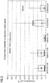
- Figure 2 shows the temporal correlation of measurements fine particulate matter and organic acid with the contamination event i.e. distribution of engine oil in the compressor section of one propulsion engine.
- the measurements were taken in the aircraft cabin during the entire flight.
- Organic acid indication correlated with the odour perception of all occupants in the cabin, both occurred during take-off and more strongly during descent.
- On the opposite particulate matter emission only occurred during take-off.
- the oil specific substances causing a smell in the cabin are not only detected in the cabin during the actual contamination (take-off) but also later on owing to retention effects in the air supply system. For this reason the monitoring of specific substances in the cabin is not the most appropriate solution; detectors are more preferably installed in the bleed system in order to get an accurate temporal correlation.
- Figure 3 shows a selection of substances which were found by traditional analytical methods in particular high concentrations during confirmed oil odours.
- formaldehyde and acetaldehyde are not only detected during every odour event but also under normal conditions or from other contamination sources. For this reason they are not specific for an oil pollution. Nevertheless their emission is greater during an odour event which represents a good complementary indication for an oil contamination.
- Substances like acetaldehyde, formic acid and acetic acid might not be exclusively indicative of engine oil contamination but occur in elevated concentrations and can be thus used as complementary indicators. In this case a comparative approach between different bleed sources can be necessary to identify the relevance and origin of the contamination.
Landscapes
- Engineering & Computer Science (AREA)
- Health & Medical Sciences (AREA)
- General Health & Medical Sciences (AREA)
- Pulmonology (AREA)
- Aviation & Aerospace Engineering (AREA)
- Mechanical Engineering (AREA)
- Chemical & Material Sciences (AREA)
- Combustion & Propulsion (AREA)
- General Engineering & Computer Science (AREA)
- General Physics & Mathematics (AREA)
- Physics & Mathematics (AREA)
- Other Investigation Or Analysis Of Materials By Electrical Means (AREA)
- Examining Or Testing Airtightness (AREA)
- Lubrication Details And Ventilation Of Internal Combustion Engines (AREA)
Description
- The invention relates to an air supply system and a method for detecting oil leakage from bleed sources. The air supply system and method can be used in aircraft to specifically detect an oil leakage and determine the origin of the oil leakage.
- Air supply systems can also be regarded as environmental control systems (ECS) that comprise an equipment in charge of maintaining a comfortable close environment in the aircraft cabin, i.e. by keeping the temperature, pressure and composition (including humidity) of the environmental air in the cabin within acceptable limits.
- The Environmental Control System thus has to provide an artificial climate in the aircraft cabin. Air from the outside has to be pressurized and temperature controlled. During flight outside air is taken from the compressor stage of the engines ("bleed air") passing a pre-cooler unit and entering the "air conditioning pack" with a temperature of approximately 200°C.
- The air conditioning pack cools the air to the required temperature using outside air ("ram air") as the cooling medium and air cycle machines for compression cooling.
- A mixer unit, installed below the cabin floor in front of the centre wing box, mixes outside air with cabin air. The cabin air, which has entered the underfloor area, is drawn through recirculation filters by recirculation fans. The recirculation fans blow the air through check valves to the mixer unit. The quantity of recirculated cabin air mixed with outside air varies from 40% to 60% in normal operating.
- On occasions carbon seals can leak small amounts of oil normally used for the bearings of the engines into the compressor stage of the engine and hence also into the bleed air. Document
US2016214724 describes an Environmental Control System including a sensor, an air purification subsystem, and a controller in communication with the sensor and air purification subsystem. The sensor detects a contaminant in the air and generates a contaminant signal. The controller compares the contaminant signal to a predicted sensory response threshold. - Due to the complexity of the overall air supply system and the mixing of air coming from different compressed air sources in the system, in case of a contamination in the bleed/compressed air system it is extremely difficult to identify the origin of the contamination.
- Several investigations were performed on pyrolysis of synthetic oils used for lubrication in bearings of aircraft engines and auxiliary power units. Often additives like Tricresylphosphates are the main subject of these investigations, as those are often claimed being neurotoxic. It is however known that the aforementioned lubricants in most cases consist of synthetic esters. It is also known that in general organic acids can be released from native fatty acid esters (vegetable oils) due to oxidative reaction or hydrolysis. The content of acids is often used as a quality benchmark of native oils (acidity of oils and fats). In the frame of experiments that have led to this invention it has been considered feasible, that similarly to vegetable oils, respective acids may be released in particular during thermal stress from synthetic ester based engine oils as well.
- The detection of specific acids released from oil used as lubricant has not yet been described in the literature as method to detect oil leakages into the air used for pressurization and ventilation of aircraft.
- The present invention is directed to the object of providing a system and a method for detecting oil leakage from bleed sources and thus for detecting oil contamination in compressed air of aircrafts. The system and method further allow the precise determination of the origin of an oil leakage, such that the oil leakage can be easily dealt with.
- The objective is solved by an air supply system according to
claim 1 and a method according to claim 9. Further preferred embodiments of the invention are described in the dependent claims. - An air supply system comprises at least two bleed sources configured to provide bleed air, wherein each bleed source comprises an engine or an auxiliary power unit and an oil as lubricant for the engine or the auxiliary power unit; at least one air conditioning pack for cooling the bleed air from the bleed sources; and a plurality of bleed ducts, wherein each bleed duct connects one of the bleed sources to the at least one air conditioning pack, characterized in that the system further comprises a plurality of detectors, wherein each detector is associated with a bleed source and the plurality of detectors are configured for detecting a substance specific for the oil, and wherein the substance specific for the oil is a substance containing a carbonyl group or a substance containing a carboxyl group.
- Each of the plurality of detectors preferably is an ion mobility spectrometer, a miniaturized mass spectrometer or a laser based infrared spectrometer (e.g. using QCLs).
- The substances specific to current jet engine oils to be detected are most preferably substances used in the formation of the ester base stock like pentanoic acid and heptanoic acid as qualifiers. Oil unspecific substances such as formaldehyde, acetaldehyde, formic acid and acetic acid are complementary indicators, which can be used as quantifiers.
- At least one of the plurality of detectors can be connected to each of the plurality of bleed ducts connecting the bleed sources to the at least one air conditioning pack, and/or at least one of the plurality of detectors can be connected to the at least one air conditioning pack.
- The air supply system can further comprise a mixer unit connected to the at least one air conditioning pack, and a plurality of mixer ducts connecting the mixer unit to the at least one air conditioning pack, wherein the mixer unit mixes cooled bleed air from the at least one air conditioning pack with air from a cabin and/or cockpit, and at least one of the plurality of detectors is connected to each of the plurality of mixer ducts connecting the mixer unit to the at least one air conditioning pack .
- The air supply system can further comprise three bleed sources comprising two engines and an auxiliary power unit, or five bleed sources comprising four engines and an auxiliary power unit; a synthetic oil as lubricant for the engines and the auxiliary power unit; at least one air conditioning pack for cooling the bleed air from the bleed sources; a plurality of bleed ducts connecting the three or five bleed sources to the at least one air conditioning pack, a mixer unit connected to the at least one air conditioning pack, a plurality of mixer ducts connecting the mixer unit to the at least one air conditioning pack, and a plurality of detectors, wherein at least one of the plurality of detectors is connected to each of the plurality of bleed ducts, the plurality of mixer ducts, and/or the at least one air conditioning pack .
- A method for detecting oil leakage from bleed sources comprises the steps of: providing bleed air through at least two bleed sources, wherein each bleed source comprises an engine or an auxiliary power unit and an oil as lubricant for the engine or the auxiliary power unit, feeding the bleed air from the at least two bleed sources to at least one air conditioning pack through a plurality of bleed ducts, cooling the bleed air from the at least two bleed sources with at least one air conditioning pack, characterized in that the system further comprises detecting substances specific for the oil with a plurality of detectors, wherein each detector is associated with a bleed source, wherein each of the plurality of detectors is configured for detecting at least one substance specific for the oil, and determining from which of the bleed sources an oil has leaked.
- Each of the plurality of detectors preferably is an ion mobility spectrometer, a miniaturized mass spectrometer, or a laser based infrared spectrometer (e.g. using QCLs).
- Preferably, said substance specific for the oil is a saturated or unsaturated, linear or branched carboxylic acid with a carbon number from 1 to 10; or a saturated or unsaturated, linear or branched aldehyde with a carbon number from 1 to 10. In a particularly preferred embodiment, the substances specific for the oil to be detected are most preferably used in the formation of the ester base stock like pentanoic acid, heptanoic acid or other precursors. Oil unspecific substances such as formaldehyde, acetaldehyde, formic acid and acetic acid are complementary indicators.
- At least one of the plurality of detectors can be connected to each of the plurality of bleed ducts connecting the bleed sources to the at least one air conditioning pack, and/or at least one of the plurality of detectors can be connected to the at least one air conditioning pack.
- The method can further comprise the steps of: detecting substances specific for the oil, wherein at least one of the plurality of detectors is connected to each of the plurality of bleed ducts connecting the bleed sources to the at least one air conditioning pack, and/or detecting substances specific for the oil, wherein at least one of the plurality of detectors is connected to the at least one air conditioning pack.
- The method can further comprise the steps of: mixing cooled bleed air from the at least one air conditioning pack with air from a cabin and/or cockpit in a mixer unit, and detecting substances specific for the oil, wherein at least one of the plurality of detectors is connected to each of the plurality of mixer ducts connecting the mixer unit to the at least one air conditioning pack.
- Preferred embodiments of the invention are explained in the following with reference to the schematic drawings, of which
- Figure 1
- shows an example of an air supply system for an aircraft;
- Figure 2
- shows the measurement of pentanoic acid and ultrafine particles taken in an aircraft cabin during a flight with provoked oil contamination in the engine compressor stage;
- Figure 3
- shows substances present in particularly higher concentration in conjunction with an oil smell.
- An
air supply system 10 shown inFigure 1 comprises at least two bleed sources 12 configured to providebleed air 14, wherein each bleed source comprises anengine 12a or anauxiliary power unit 12b and an oil as lubricant for the engine or the auxiliary power unit; at least oneair conditioning pack 16 for cooling the bleed air from the bleed sources; and a plurality ofbleed ducts 18, wherein each bleed duct connects one of the bleed sources to the at least one air conditioning pack, characterized in that the system further comprises a plurality ofdetectors 20, wherein each detector is associated with a bleed source and the plurality of detectors are configured for detecting substances specific for the oil. - An air supply system is a system that can provide a comfortable environment to the cabin and cockpit of an aircraft. The air supply system can also be regarded as an environmental control system of which specific parts and components are described in further detail in the following. Even though air supply systems or environmental control systems are complex systems comprising many interrelated components, the main components required for carrying out the present invention are those described above and in the claims. The skilled person is able to identify further components that can be added to the air supply system without impeding the nature of the invention.
- The environmental control system ECS is an equipment in charge of maintaining a comfortable close environment in the aircraft cabin, i.e. by keeping the temperature, pressure and composition including room humidity of the environmental air in the cabin within acceptable limits.
- The Environmental Control System thus has to provide an artificial climate in the aircraft cabin. Air from the outside has to be pressurized and temperature controlled. During flight outside air is taken from the compressor stage of the engines "bleed air" passing a pre-cooler unit and entering the "air conditioning pack" with a temperature of approximately 200°C. The outside air can also be compressed via electrical compressors. The air conditioning packs can also be supplied via the Auxiliary Power Unit a turbine driven air compressor and electrical generator or a ground based source via the high pressure ground connector.
- The air conditioning pack cools the air to the required temperature using outside air "ram air" as the cooling medium and air cycle machines for compression cooling. In principle this represents a two-stage compression process with subsequent cooling after each compression and finally the expansion cooling of the supplied outside air which enters the pressurized fuselage passing a check valve in the pressure bulkhead.
- A mixer unit, installed below the cabin floor in front of the centre wing box, mixes outside air with cabin air. The cabin air, which has entered the underfloor area, is drawn through recirculation filters by recirculation fans. The recirculation fans blow the air through check valves to the mixer unit. The quantity of recirculated cabin air mixed with outside air varies from 40% to 60% in normal operating.
- Due to the complexity of the overall air supply system and the mixing of air coming from different compressed air sources in the system, in case of a contamination in the bleed/compressed air system it is extremely difficult to identify the origin of the contamination, by selecting different system configurations. Detectors positioned in a direct connection with singular bleed sources can be very useful to narrow down the potential origin of the contamination. This can also be the case if this connection is only temporarily dedicated to a singular bleed source depending on the operation the same duct can be used by different sources and partially in different flow directions e.g. during engine start.
- During flight tests with an artificial contaminated engine it was observed that the first occurrence of generated odour mainly caused by organic acids released was accompanied by a steep increase of fine particulate matter i.e. < 1µm in diameter. The second occurrence of odour did not show this behaviour and is attributed to the system complexity where odorous substances mainly organic acids can be adsorbed or condensed and later on - due to an increase of temperature - can be released and consequently provoke odour in the cabin. However, this second odour occurrence does not have a temporal relation to the actual contamination event and could hardly be attributed to a specific origin once the origin is not known. Therefore it is considered sensible to measure the indicative substances for an oil contamination directly in the bleed air duct or any duct with direct connection and clearly relatable to any given bleed air source with a minimum of temperature and pressure changes, which can be necessary to adapt these parameters to the operating range of the respective sensor.
- Detection of substances specific to thermally degraded engine oil like pentanoic acid or heptanoic acid in the bleed air system can help to quickly identify the source of contamination and initiate respective countermeasures in case of an obvious event but also can serve as monitoring method for proactive maintenance.
- The engines of an aircraft, in addition to providing thrust, have to deliver electrical, pneumatic and hydraulic secondary power to the systems in the aircraft. Among these systems, the ECS is the main power consumer which can for example be about 75% of non-propulsive power energy, which can be about 1% of the propulsion energy and it generates the most important extra consumption of fuel.
- With engines off on the ground, the auxiliary power unit APU, as described above, provides electrical power and bleed air for air conditioning and the start of the main-engines.
- The pneumatic system of an aircraft can include bleed air at 250 kPa and 450 K for the internal ECS, i.e. cabin air.
- The cabin air conditioning must provide comfort conditions, which can be set at 22±2°C, 90-100 kPa and 50-70% RH under all foreseeable circumstances, such as outer temperatures ranging from -60 to +50°C, outer pressures of 10 to 110 kPa, 0-100 % RH, ozone, etc. The ECS must therefore provide ventilation, pressurization, heating, cooling, humidification, deshumidification demisting of windows and disinfection.
- In a typical setup of an ECS, air is bled from the main engine compressors through a flow control valve at around 250 kPa. Said compressed air is very hot e.g. > 200 °C, because of the adiabatic compression-heating.
- As pressure and temperature of this bleed air varies according to which compressor stage is used and the power setting of the engine, the pressure is regulated by having two or three bleedings at different stages and control valves. A manifold pressure regulating shut-off valve MPRSOV restricts the flow as necessary to maintain the desired pressure for downstream systems. A certain minimum supply pressure is needed to drive the air through the system, but it can be desired to use as low a supply pressure as possible, because the energy the engine uses to compress the bleed air is not available for propulsion, and fuel consumption suffers. For this reason, air is commonly drawn from one of two bleed ports at different compressor stage locations. When the engine is at low pressure low thrust or high altitude, the air is drawn from the highest pressure bleed port. As pressure is increased and reaches a predetermined crossover point, the high pressure shut-off valve HPSOV closes and air is selected from a lower pressure port to minimize the fuel performance loss. The reverse happens as engine pressure decreases.
- The hot bled air requires cooling before entering the cabin. A simple heat exchanger HE with outside air might not be efficient for this task.
- To guarantee that bled air can be safely piped from the engine through the fuselage to the air-cycle machine and deicing system, a heat-exchanger pre-cooler in the engine can cool bled air from the compressor at >200 °C to about 200 °C. Precooled air from the bleed system can be further cooled in a primary heat exchanger down to about 110 °C, and then enters a compressor that raises the air to about 210 °C, and a second heat exchanger lowers the temperature again to about 100 °C.
- Afterwards, air can pass through a turbine and exit at about 5 °C, to be mixed with some hotter bled air at around 100-200 °C to get the 10 to 35 °C needed to keep the cabin air at around 22 °C, accounting for internal heat release from passengers and equipment, outside heat gain and loses, and air recirculation.
- Additional filters/separators can be provided to remove water condensate on ground and low altitudes in humid climates. Said filters/separators are arranged just downstream the air cycle machine ACM turbine in most cases, and upstream the turbine, when very cold cabin air is needed on ground, to avoid the risk of icing inside the turbine. The condensate is injected into the ram air stream to help HE efficiency. Additionally high efficiency particulate arresting HEPA filters can be used, which trap more than 99% of all bacteria and clustered viruses.
- Ram air can be used as a heat sink in both heat exchangers. Ram air can be captured through an inlet door and a diffuser, and forced by a fan driven by the ACM turbine to go through the two heat exchangers mentioned above, a exhaust nozzle, and a louvered exit door.
- The resulting air can be directed to overhead distribution nozzles in the various "zones" of the aircraft. Temperature in each zone can be adjusted by adding small amounts of "trim air", which is high-pressure, high-temperature air tapped off an A/C pack downstream of the FCV and upstream the pack. Air is also supplied to individual gaspers: small, circular vents above each passenger seat that can be adjusted by passengers for their personal comfort. A revolving control on the vent can be turned to adjust ventilation between no air output at all and a fairly substantial breeze.
- Two equal air cycle machine nominal systems can be implemented, to allow for one failure of one of the air cycle machine systems.
- A bleed source is a source that can provide compressed air into an air supply system. Said compressed air is also referred to as bleed air in the technical field of the present invention. Common bleed sources in aircrafts are engines and auxiliary power units, but also other kinds of air compressors.
- Bleed air produced by gas turbine engines is compressed air that is taken from the compressor stage of those engines, which is upstream of the fuel-burning sections. In modern airliner engines, two regulator valves high stage and low stage turn on and off automatically and are controlled by at least two air supply and cabin pressure controllers ASCPCs which open and close appropriate valves. Engine Bleed Air comes from the high stage or low stage engine compressor section. Low stage air is used during high power setting operation and high stage air is used during descent and other low power setting operations. Bleed air from that system can be used for internal cooling of the engine, cross-starting another engine, engine and airframe anti-icing, cabin pressurization, pneumatic actuators, air-driven motors, pressurizing the hydraulic reservoir, waste and water storage tanks. Some engine maintenance manuals refer to such systems as "Customer Bleed Air. Bleed air is valuable in an aircraft for two properties: high temperature and high pressure. Ttypical values are 200-250 °C and 275 kPa, for regulated bleed air exiting the engine pylon for use throughout the aircraft.
- An auxiliary power unit APU is a device on a vehicle such as an aircraft that provides energy for functions other than propulsion. The primary purpose of an aircraft APU is to provide power to start the main engines. Turbine engines must be accelerated at a high rotational speed to provide sufficient air compression for self-sustaining operation. However, APUs are also used to run accessories while the engines are shut down. This allows the cabin to be comfortable, while the passengers are boarding before the aircraft's engines are started. APUs also are a critical safety device, as they supply backup electricity and compressed air in place of a dead engine of failed main engine generator. APUs are also used in environmental control system ECS of aircrafts and support the provision of an artificial climate in the aircraft cabin.
- The oil used as lubricant for the engine or the auxiliary power unit is also called engine oil or engine lubricant and is a substance that can be oil enhanced with additives that are used for lubrication of internal combustion engines. Motor oils are derived from petroleum-based and non-petroleum-synthesized chemical compounds.
- Synthetic lubricant oils are preferably used herein.
- Motor oils can be blended by using base oils composed of hydrocarbons, polyalphaolefins PAO, and polyinternal olefins PIO, i.e. organic compounds consisting entirely of carbon and hydrogen.
- Engine oil or engine lubricant is used for the lubrication, cooling, and cleaning of internal combustion engines. Lubricant base stocks are categorized into five groups by the American Petroleum Institute API. It is noted that there are also ways of categorizing lubricants, to which this application does not make reference. Group I base stocks are composed of fractionally distilled petroleum which is further refined with solvent extraction processes to improve certain properties such as oxidation resistance and to remove wax. Group II base stocks are composed of fractionally distilled petroleum that has been hydrocracked to further refine and purify it. Group III base stocks have similar characteristics to Group II base stocks, except that Group III base stocks have higher viscosity indexes. Group III base stocks are produced by further hydrocracking of either Group II base stocks or hydroisomerized slack wax a Group I and II dewaxing process by-product. Group IV base stock are polyalphaolefins PAOs. Group V is a catch-all group for any base stock not described by Groups I to IV. Examples of group V base stocks include polyolesters POE, polyalkylene glycols PAG,
and perfluoropolyalkylethers PFPAEs. Groups I and II are commonly referred to as mineral oils, group III is typically referred to as synthetic and group IV is a synthetic oil. Group V base oils are so diverse that there is no catch-all description. - Oils that are used as lubricants consist of hydrocarbons. Due to thermal degradation of the oil, substances such as carboxylic acids and aldehydes are released. Some of those are rather non-specific and could be released from other thermally degraded hydrocarbons as well. The specific substances to be detected are most preferably the precursors used in the production of the base stock of the oil like pentanoic acid and heptanoic acid or alternative precursors. Oil unspecific substances such as formaldehyde, acetaldehyde, formic acid and acetic acid are complementary indicators of an oil leakage.
- Specific oils or which above mentioned markers have determined to be adequate are mobile jet oil II and BP Turbo oil.
- In addition to viscosity index improvers, engine oil or engine lubricant can include other additives such as detergents and dispersants to help keep the engine clean by minimizing sludge buildup, corrosion inhibitors, and alkaline additives to neutralize acidic oxidation products of the oil.
- Additives can be extreme-pressure EP additives such as aliphatic chlorinated hydrocarbons chlorinated paraffins, e.g. chloroalkanes, trichloromethyl phosphine acids, organic esters of a-acetoxy-b,b,b-trichloroethyl phosphonic acid, trichloromethyl esters of phosphoric acid, trichloromethyl derivates of sulfur, trichloroacetoxy compounds, esters or amine salts of chlorendic acid, 1,2,3,4,7,7-hexachloro-5-dimethylbicyclo[2.2.1]-2-heptene. EP additives, like zinc dialkyldithiophosphate ZDDP additives and sulfonates, preferably calcium sulfonates, are used for additional protection under extreme-pressure conditions or in heavy duty performance situations. ZDDP starts decomposing at 130-170 °C, while the activation temperature of 1,2,3-Trichloropropane TCP typically exceeds 200 °C. Their reaction products form a chemically bonded lubricating film on the surfaces. Calcium sulfonates additives are also added to protect engine oil or engine lubricant from oxidative breakdown and to prevent the formation of sludge and varnish deposits.
- Some molybdenum disulfide containing additives to lubricating oils can reduce friction, bond to metal, or have anti-wear properties. MoS2 particles can be shear-welded on steel surface and some engine components are treated with MoS2 layer during manufacture, namely liners in engines. Molybdenum compounds decompose under high pressure to form an in-situ deposited layer of molybdenum disulfide. Molybdenum dithiocarbamates are used as additives for greases.
Sulfur containing extreme pressure additives do not cause corrosion problems in gears with parts made of bronze, brass and other copper alloy when high temperature environments are encountered, if they have the presence of lubrification oil. - Other additives are oil-soluble organophosphates, with or without zinc that have excellent high-pressure and antiwear properties, and provide corrosion protection especially in presence of chlorinated hydrocarbons.
- Also additives such as polysulfides can be used, which serve as carriers of inactive and active sulfur.
- Additives can also be antiwear additives which are additives for lubricants to prevent metal-to-metal contact between parts of gears. Antiwear additives can be zinc dithiophosphate ZDP, tricresyl phosphate TCP for high-temperature operation in turbine engine lubricants, halocarbons chlorinated paraffins for extreme pressure operations, glycerol mono oleate, stearic acid adhering to surfaces via reversible adsorption process under 150 °C, Under extreme pressure conditions, the performance of AW additives becomes insufficient and designated EP additives are required.
- From the above, zinc dialkyl dithio phosphate ZDDP is the preferred additive, as it acts as antiwear additive, as a corrosion inhibitor and antioxidant.
- The preferred detectors used for the detection of substances specific for oil are ion-mobility spectrometers IMS, miniature mass spectrometer MMS or laser based infrared spectrometers. Ion-mobility spectrometry is an analytical technique used to separate and identify ionized molecules in the gas phase based on their mobility in a carrier buffer gas. IMS devices can be tailored for a specific application and can be miniaturized to small sizes. Systems operated at higher pressure i.e. atmospheric conditions, 1 atm or 1013 mbar are also accompanied by elevated temperature above 100 °C, while lower pressure systems 1-20 mbar do not require heating. The detection limit is below ppb parts per billion, the speed at which separations occur in an IMS are typically on the order of tens of milliseconds and a wide variety of substance classes can be detected by an IMS.
- In a schematic explanation of an IMS, produced ions travel through a drift tube which has an applied electric field and a carrier buffer gas that opposes the ion motion. At the end of the tube is a detector. Based on an ion's mass, charge, size and shape the ion mobility, the migration time through the tube is characteristic of different ions, leading to the ability to distinguish different analyte species. In this respect, the ions are on the one hand accelerated by the applied electrical field and on the other hand are slowed down by collision with the carrier buffer gas. The resulting speed at which the ions strike a detector is characteristic for the specific ion.
- The area of an ion that gas molecules strike is an ion's collision cross-section, related to the ion size and shape. The greater this collision cross-section is, meaning the larger the ion size, the more area available for buffer gas to collide and impede the ion's drift - the ion then requires a longer time to migrate through the drift tube. IMS devices comprise an ionizer, usually a corona discharge, atmospheric pressure photoionization APPI, electrospray ionization ESI, or radioactive source. ESI and MALDI techniques can also be used when IMS is paired with mass spectrometry.
- The analyzer can be a TOFIMS, which measures how fast a given ion moves in a uniform electric field through a given atmosphere. In specified intervals, a sample of the ions is let into the drift chamber. Once in the drift tube, ions are subjected to a homogeneous electric field ranging from a few volts per centimeter up to many hundreds of volts per centimeter. This electric field then drives the ions through the drift tube where they interact with the neutral drift molecules contained within the system. In the drift tube, chemical species separate based on the ion mobility, arriving at the detector for measurement. Ions are recorded at the detector in order from the fastest to the slowest, generating a response signal characteristic for the chemical composition of the measured sample. Other analyzers that can be employed are DMS/FAIMS differential mobility spectrometer / High-field asymmetric waveform ion mobility spectrometry and DMAs differential mobility analyzer.
- The drift gas pressure is an important parameter for the IMS instrument design and resolution. Most drift gases have a higher break down voltage at pressures higher than a few mbar, with the break down voltage increasing as the pressure increases. As an example, high drift voltages of about 10-30 kV can be used with tubes of 1 m length and high gas pressures of 100-1000 mbar to obtain high resolutions. At higher pressures than 10 mbar, ions become more difficult to store. At lower pressures, ions can be stored more easily to obtain an accumulated continuous signal, with the trade-off of lower electric fields around 10-30 V/cm. Elevated gas temperature assists in removing ion clusters that can distort experimental measurements.
- The detector can be a simple Faraday plate, or a mass spectrometers can be coupled to the IMS, such that both size and mass information can be obtained simultaneously.
- A miniature mass spectrometer MMS is a type of mass spectrometer, which has a small size and weight and is usually understood as a portable or handheld device. Such devices are known in the art and can be used according to the skilled persons knowledge.
- The substance specific for the oil is a substance containing a carbonyl group, or a substance containing a carboxyl group. Preferably, said substance specific for the oil is a saturated or unsaturated, linear or branched carboxylic acid with a carbon number from 1 to 10; or a saturated or unsaturated, linear or branched aldehyde with a carbon number from 1 to 10. In a particularly preferred embodiment, the substance specific to be detected are most preferably substances used as precursors for the base stock of the oil like pentanoic acid and heptanoic acid. Oil unspecific substances such as formaldehyde, acetaldehyde, formic acid and acetic acid are complementary indicators of an oil leakage.
- At least one of the plurality of
detectors 20 can be connected to each of the plurality ofbleed ducts 18 connecting the bleed sources 12 to the at least oneair conditioning pack 16, and/or at least one of the plurality ofdetectors 20 can be connected to the at least oneair conditioning pack 16. - Accordingly, at least one
detector 20 is located directly downstream of each of the bleed sources. Each bleed source has thus at least one detector associated to the bleed source. Each of the detectors allows for the measurement of an oil leakage immediately downstream of the bleed sources. Each detector allows the detection of an oil leakage at an individual of the bleed sources. - The detectors can preferably be located between the bleed source and the at least one
air conditioning pack 16. The detectors can also be located at the at least oneair conditioning pack 16. The detectors can also be located between the at least oneair conditioning pack 16 and themix manifold 22. The detectors can also be located between the bleed source and thehot manifold 30 - The detectors are preferably be connected to the
bleed duct 18 connecting the bleed source 12 and the at least oneair conditioning pack 16. The detectors can also be connected directly to the at least oneair conditioning pack 16. The detectors can also be connected to the mixer duct connecting the at least oneair conditioning pack 16 to themix manifold 22 ormixer unit 22. The detectors can also be connected to the duct between the bleed source 12 and thehot manifold 30. Detectors can be also connected downstream the high pressure ground connector to cover hot air supply by a ground supply unit. - In case the pressure and/or temperature of the bleed air is too high, the bleed air can be at least partially cooled and/or depressurized before it is fed to the
detector 20. - The
air supply system 10 can further comprise amixer unit 22 ormix manifold 22 connected to the at least one air conditioning pack, and a plurality ofmixer ducts 24 connecting the mixer unit to the at least one air conditioning pack, wherein themixer unit 22 mixes cooled bleed air from the at least oneair conditioning pack 24 with air from acabin 26 and/orcockpit 28, and at least one of the plurality ofdetectors 20 is connected to each of the plurality ofmixer ducts 24 connecting themixer unit 22 to the at least oneair conditioning pack 16. - The
air supply system 10 can further comprise three bleed sources 12 comprising twoengines 12a and anauxiliary power unit 12b, or five bleed sources 12 comprising fourengines 12a and anauxiliary power unit 12b; a synthetic oil as lubricant for the engines and the auxiliary power unit; at least oneair conditioning pack 16 for cooling the bleed air from the bleed sources; a plurality ofbleed ducts 18 connecting the three or five bleed sources 12 to the at least oneair conditioning pack 16, amixer unit 22 connected to the at least oneair conditioning pack 16, a plurality ofmixer ducts 24 connecting themixer unit 22 to the at least oneair conditioning pack 16, and a plurality ofdetectors 20, wherein at least one of the plurality of detectors is connected to each of the plurality ofbleed ducts 18, the plurality ofmixer ducts 24, and/or the at least oneair conditioning pack 16. - The air supply system can further comprise a
hot manifold 30, awing anti-ice system 32, anozone converter 34 for converting ozone into oxygen,ground connectors 36, a feed forram air 38, anavionic system 40, afilter 42 and arecirculation fan 44. - A method for detecting oil leakage from bleed sources comprises the steps of: providing bleed air through at least two bleed sources, wherein each bleed source comprises an engine or an auxiliary power unit and an oil as lubricant for the engine or the auxiliary power unit, feeding the bleed air from the at least two bleed sources to at least one air conditioning pack through a plurality of bleed ducts, cooling the bleed air from the at least two bleed sources with at least one air conditioning pack, characterized in that the system further comprises detecting a substance specific for the oil with a plurality of detectors, wherein each detector is associated with a bleed source, wherein each of the plurality of detectors is configured for detecting one or several substances specific for the oil and wherein the substance specific for the oil is a substance containing a carbonyl group or a substance containing a carboxyl group, and determining from which of the bleed sources an oil has leaked.
- Each of the plurality of
detectors 20 preferably is an ion mobility spectrometer or a miniaturized mass spectrometer. - The substance specific for the oil is a substance containing a carbonyl group, or a substance containing a carboxyl group. Preferably, said substance specific for the oil is a saturated or unsaturated, linear or branched carboxylic acid with a carbon number from 1 to 10; or a saturated or unsaturated, linear or branched aldehyde with a carbon number from 1 to 10. In a particularly preferred embodiment, the substances specific for the oil to be detected are most preferably used as precursors for the base stock of the oil like pentanoic acid and heptanoic acid. Oil unspecific substances such as formaldehyde, acetaldehyde, formic acid and acetic acid are complementary indicators of an oil leakage.
- At least one of the plurality of
detectors 20 can be connected to each of the plurality ofbleed ducts 18 connecting the bleed sources 12 to the at least oneair conditioning pack 16, and/or at least one of the plurality ofdetectors 20 can be connected to the at least oneair conditioning pack 16. - The method can further comprise the steps of: detecting substances specific for the oil, wherein at least one of the plurality of detectors is connected to each of the plurality of bleed ducts connecting the bleed sources to the at least one air conditioning pack, and/or detecting substances specific for the oil, wherein at least one of the plurality of detectors is connected to the at least one air conditioning pack.
- The method can further comprise the steps of: mixing cooled bleed air from the at least one air conditioning pack with air from a cabin and/or cockpit in a mixer unit, and detecting substances specific for the oil, wherein at least one of the plurality of detectors is connected to each of the plurality of mixer ducts connecting the mixer unit to the at least one air conditioning pack.
- According to the present invention, the air supply system of a vehicle such as an aircraft using engine- or APU-compressed air can be equipped with detectors or sensors or a set of detectors, which can detect substances or substance groups specifically released from oil that is used as lubricant in the engine or APU.
- As the detectors are located in the air supply system, e.g. directly downstream of the bleed source instead of being located in the cabin or cockpit,, they allow the precise location of an oil leakage. Accordingly, the bleed source, i.e. engine or APU from which the oil has leaked can be identified and appropriate counter-measures can be adapted.
- More precisely, the detectors are located downstream of each of the bleed sources and thus each bleed sources has its own detector. Once a detector detects a substance specific for an oil, such as pentanoic acid or heptanoic acid, one can derive that the corresponding bleed source leaks oil.
- This has the advantage that, as opposed to a detector that would be located in the cabin or cockpit of the aircraft, the precise location of the oil leakage can be detected. In case the detector is located in the cabin or cockpit, one would be able to identify that there is an oil leak. As the oil leak is usually accompanied by a strong smell event, no essentially new information is provided by such a detector in the cabin or cockpit. By the provision of a detector for each of the bleed sources, the origin of the oil leakage can be precisely determined.
- Oil leakages in the bleed system of engines and APUs can thus be detected by the detection of specific substances released from thermally degraded oil in the bleed air flow and hence indicate the origin of the contamination.
- In order to narrow down the root cause of a potential pollution each compressed air source is equipped with a separate detector or set of detectors in the respective supply duct.
- The response of the detectors in the compressed air system can be used to identify the root cause of contamination either based on their individual response or in terms of a comparative analysis i.e. compare the responses of different detectors for example in case external pollution triggers the sensor response. The response of the detectors can be used as singular trigger for an informative message, serve as additional information in case a problem is assumed or as information for aircraft maintenance.
- In the specific embodiment shown in
Figure 1 , an air supply system for an aircraft comprising four engines is shown. Additionally, potential positions of detectors for substances or substance groups released from the thermally degraded lubricant oil are marked. Detectors connected to the trim air system in the pressurized area can differentiate between left and right wing bleed air and hence between engines in case of aircraft with two engines only. Detectors in the pack as constituent assembly or directly after the pack are also adequate solutions. -
Figure 2 shows the temporal correlation of measurements fine particulate matter and organic acid with the contamination event i.e. distribution of engine oil in the compressor section of one propulsion engine. The measurements were taken in the aircraft cabin during the entire flight. Organic acid indication correlated with the odour perception of all occupants in the cabin, both occurred during take-off and more strongly during descent. On the opposite particulate matter emission only occurred during take-off. As a matter of fact, the oil specific substances causing a smell in the cabin are not only detected in the cabin during the actual contamination (take-off) but also later on owing to retention effects in the air supply system. For this reason the monitoring of specific substances in the cabin is not the most appropriate solution; detectors are more preferably installed in the bleed system in order to get an accurate temporal correlation. -
Figure 3 shows a selection of substances which were found by traditional analytical methods in particular high concentrations during confirmed oil odours. Substances like C5 to C8 organic acids, pentanoic acid to octanoic acid rarely occur under normal conditions but were always detected during an oil odour event and their concentrations exceed typical levels found in indoor and environmental air. These substances are thus rather specific for oil pollution. On the other hand, formaldehyde and acetaldehyde are not only detected during every odour event but also under normal conditions or from other contamination sources. For this reason they are not specific for an oil pollution. Nevertheless their emission is greater during an odour event which represents a good complementary indication for an oil contamination. - Substances like acetaldehyde, formic acid and acetic acid might not be exclusively indicative of engine oil contamination but occur in elevated concentrations and can be thus used as complementary indicators. In this case a comparative approach between different bleed sources can be necessary to identify the relevance and origin of the contamination.
Claims (13)
- Air supply system (10) comprising- at least two bleed sources (12) configured to provide bleed air (14), wherein each bleed source comprises an engine (12a) or an auxiliary power unit (12b) and an oil as lubricant for the engine or the auxiliary power unit;- at least one air conditioning pack (16) for cooling the bleed air from the bleed sources; and- a plurality of bleed ducts (18), wherein each bleed duct connects one of the bleed sources to the at least one air conditioning pack,
and- a plurality of detectors (20),characterized in that
each detector is associated with a bleed source and the plurality of detectors are configured for detecting a substance specific for the oil, and wherein the substance specific for the oil is a substance containing a carbonyl group or a substance containing a carboxyl group. - Air supply system (10) according to claim 1, wherein each of the plurality of detectors (20) is an ion mobility spectrometer, a miniaturized mass spectrometer or a laser based infrared spectrometer.
- Air supply system (10) according to any of the preceding claims, wherein the substance specific for the oil is a precursor used for the production of the base stock of respective oil.
- Air supply system (10) according to any of the preceding claims, wherein the substance specific for the oil is- a saturated or unsaturated, linear or branched carboxylic acid with a carbon number from 1 to 10;- a saturated or unsaturated, linear or branched aldehyde with a carbon number from 1 to 10;- pentanoic acid, heptanoic acid, octanoic acid or tiglic acid.
- Air supply system (10) according to any of the preceding claims, wherein- at least one of the plurality of detectors (20) is connected to each of the plurality of bleed ducts (18) connecting the bleed sources (12) to the at least one air conditioning pack (16), and/or- at least one of the plurality of detectors (20) is connected to the at least one air conditioning pack (16).
- Air supply system (10) according to any of the preceding claims, further comprising- a mixer unit (22) connected to the at least one air conditioning pack, and- a plurality of mixer ducts (24) connecting the mixer unit to the at least one air conditioning pack,wherein- the mixer unit (22) mixes cooled bleed air from the at least one air conditioning pack (24) with air from a cabin (26) and/or cockpit (28), and- at least one of the plurality of detectors (20) is connected to each of the plurality of mixer ducts (24) connecting the mixer unit (22) to the at least one air conditioning pack (16).
- Air supply system (10) according to any of the preceding claims comprising- three bleed sources (12) comprising two engines (12a) and an auxiliary power unit (12b), or five bleed sources (12) comprising four engines (12a) and an auxiliary power unit (12b);- a synthetic oil as lubricant for the engines and the auxiliary power unit;- at least one air conditioning pack (16) for cooling the bleed air from the bleed sources;- a plurality of bleed ducts (18) connecting the three or five bleed sources (12) to the at least one air conditioning pack (16),- a mixer unit (22) connected to the at least one air conditioning pack (16),- a plurality of mixer ducts (24) connecting the mixer unit (22) to the at least one air conditioning pack (16), and- a plurality of detectors (20), wherein at least one of the plurality of detectors is connected to each of the plurality of bleed ducts (18), the plurality of mixer ducts (24), and/or the at least one air conditioning pack (16).
- Method for detecting oil leakage from bleed sources comprising the steps of:- providing bleed air through at least two bleed sources, wherein each bleed source comprises an engine or an auxiliary power unit and an oil as lubricant for the engine or the auxiliary power unit,- feeding the bleed air from the at least two bleed sources to at least one air conditioning pack through a plurality of bleed ducts,- cooling the bleed air from the at least two bleed sources with at least one air conditioning pack,- detecting substances specific for the oil with a plurality of detectors, wherein each detector is associated with a bleed source, and- determining from which of the bleed sources an oil has leaked, characterized in that each of the plurality of detectors is configured for detecting a substance specific for the oil wherein the substance specific for the oil is a substance containing a carbonyl group or a substance containing a carboxyl group.
- Method for detecting oil leakage from bleed sources according to claim 8,
wherein each of the plurality of detectors is an ion mobility spectrometer or a miniaturized mass spectrometer. - Method for detecting oil leakage from bleed sources according to any one of claims 8 to 9, wherein the substance specific for the oil is- a saturated or unsaturated, linear or branched carboxylic acid with a carbon number from 1 to 10; or- a saturated or unsaturated, linear or branched aldehyde with a carbon number from 1 to 10.
- Method for detecting oil leakage from bleed sources according to any one of claims 8 to 10, wherein the substance specific for the oil is pentanoic acid, heptanoic acid, octanoic acid or tiglic acid.
- Method for detecting oil leakage from bleed sources according to any one of claims 8 to 11, wherein the method further comprises the steps of:- detecting substances specific for the oil, wherein at least one of the plurality of detectors is connected to each of the plurality of bleed ducts connecting the bleed sources to the at least one air conditioning pack, and/or- detecting substances specific for the oil, wherein at least one of the plurality of detectors is connected to the at least one air conditioning pack.
- Method for detecting oil leakage from bleed sources according to any one of claims 8 to 12, further comprising the steps of:- mixing cooled bleed air from the at least one air conditioning pack with air from a cabin and/or cockpit in a mixer unit, and- detecting substances specific for the oil, wherein at least one of the plurality of detectors is connected to each of the plurality of mixer ducts connecting the mixer unit to the at least one air conditioning pack.
Priority Applications (3)
| Application Number | Priority Date | Filing Date | Title |
|---|---|---|---|
| EP16199745.7A EP3323728B1 (en) | 2016-11-21 | 2016-11-21 | System and method for determining the origin of an oil leakage in an air supply system |
| CN201711135139.7A CN108082493B (en) | 2016-11-21 | 2017-11-16 | System and method for determining the source of oil leakage in an air supply system |
| US15/815,876 US11518521B2 (en) | 2016-11-21 | 2017-11-17 | System and method for determining the origin of an oil leakage in an air supply system |
Applications Claiming Priority (1)
| Application Number | Priority Date | Filing Date | Title |
|---|---|---|---|
| EP16199745.7A EP3323728B1 (en) | 2016-11-21 | 2016-11-21 | System and method for determining the origin of an oil leakage in an air supply system |
Publications (2)
| Publication Number | Publication Date |
|---|---|
| EP3323728A1 EP3323728A1 (en) | 2018-05-23 |
| EP3323728B1 true EP3323728B1 (en) | 2019-01-02 |
Family
ID=57389254
Family Applications (1)
| Application Number | Title | Priority Date | Filing Date |
|---|---|---|---|
| EP16199745.7A Active EP3323728B1 (en) | 2016-11-21 | 2016-11-21 | System and method for determining the origin of an oil leakage in an air supply system |
Country Status (3)
| Country | Link |
|---|---|
| US (1) | US11518521B2 (en) |
| EP (1) | EP3323728B1 (en) |
| CN (1) | CN108082493B (en) |
Families Citing this family (5)
| Publication number | Priority date | Publication date | Assignee | Title |
|---|---|---|---|---|
| DE102016201924A1 (en) * | 2016-02-09 | 2017-08-10 | Lufthansa Technik Aktiengesellschaft | Aircraft and warning device for an "engine oil smell" in an aircraft cabin of an aircraft |
| US20200248580A1 (en) * | 2019-02-05 | 2020-08-06 | United Technologies Corporation | Duct rupture detection system |
| EP3882152A1 (en) * | 2020-03-17 | 2021-09-22 | Hamilton Sundstrand Corporation | Electro-pneumatic powered environmental control system |
| FR3117455B1 (en) * | 2020-12-11 | 2023-04-14 | Liebherr Aerospace Toulouse Sas | AIRCRAFT DISTRIBUTED PNEUMATIC POWER SYSTEM |
| US20230228214A1 (en) * | 2022-01-19 | 2023-07-20 | General Electric Company | Bleed flow assembly for a gas turbine engine |
Family Cites Families (15)
| Publication number | Priority date | Publication date | Assignee | Title |
|---|---|---|---|---|
| US5511385A (en) * | 1994-12-23 | 1996-04-30 | United Technologies Corp. | Independent compartment temperature control for single-pack operation |
| US6438938B1 (en) * | 2000-11-28 | 2002-08-27 | Rolls-Royce Corporation | Bearing compartment self cooling vent system |
| US6737988B2 (en) * | 2002-02-21 | 2004-05-18 | Honeywell International, Inc. | Instrumentation and control circuit having multiple, dissimilar sources for supplying warnings, indications, and controls and an integrated cabin pressure control system valve incorporating the same |
| US7052525B2 (en) * | 2002-08-13 | 2006-05-30 | Ensco, Inc. | Vehicle integrated protective system |
| JP2008062361A (en) | 2006-09-11 | 2008-03-21 | Nippon Oil Corp | Cutting/grinding method using extremely trace amount lubricant and oil composition for cutting/grinding processing using extremely trace amount lubricant |
| GB2447042B (en) * | 2007-02-27 | 2011-11-09 | Building Res Establishment Ltd | Apparatus and method for air sampling |
| BRPI0822511B1 (en) * | 2008-03-10 | 2019-03-19 | Airsense Analytics Gmbh | PROCESS FOR GAS DETECTION AND IDENTIFICATION IN AIRCRAFT INTERNAL AREAS |
| US8938973B2 (en) * | 2010-02-11 | 2015-01-27 | Pratt & Whitney Canada Corp. | Air contamination detection in an aircraft air system |
| CN105229125B (en) * | 2013-05-14 | 2018-12-18 | 巴斯夫欧洲公司 | Lubricant oil composite with enhancing energy efficiency |
| US9666781B2 (en) * | 2013-08-19 | 2017-05-30 | The Boeing Company | Methods for recovering waste energy from bleed air ducts |
| US9662626B2 (en) * | 2014-06-25 | 2017-05-30 | Honeywell International Inc. | Photocatalyst air purification system with ultraviolet light emitting diodes operated with a duty cycle |
| US9776725B2 (en) * | 2015-01-27 | 2017-10-03 | Honeywell International Inc. | Human factors approach to control contaminant concentrations in aircraft supply air from engine and APU bleed air and ground air sources, and in recirculated air being delivered to aircraft cabins for the optimization of user experience and energy consumption |
| US9957052B2 (en) * | 2015-01-27 | 2018-05-01 | Honeywell International Inc. | Aircraft environmental control system that optimizes the proportion of outside air from engines, APU's, ground air sources and the recirculated cabin air to maintain occupant comfort and maximize fuel economy |
| CA2985965C (en) * | 2015-05-22 | 2023-04-11 | Bombardier Inc. | Aircraft air quality monitoring system and method |
| WO2016189421A1 (en) * | 2015-05-22 | 2016-12-01 | Bombardier Inc. | Airflow management in cabin of aircraft |
-
2016
- 2016-11-21 EP EP16199745.7A patent/EP3323728B1/en active Active
-
2017
- 2017-11-16 CN CN201711135139.7A patent/CN108082493B/en active Active
- 2017-11-17 US US15/815,876 patent/US11518521B2/en active Active
Non-Patent Citations (1)
| Title |
|---|
| None * |
Also Published As
| Publication number | Publication date |
|---|---|
| CN108082493A (en) | 2018-05-29 |
| US11518521B2 (en) | 2022-12-06 |
| EP3323728A1 (en) | 2018-05-23 |
| CN108082493B (en) | 2021-07-20 |
| US20180141665A1 (en) | 2018-05-24 |
Similar Documents
| Publication | Publication Date | Title |
|---|---|---|
| US11518521B2 (en) | System and method for determining the origin of an oil leakage in an air supply system | |
| EP3050801B1 (en) | Aircraft environmental control system that optimizes the proportion of outside air from engines, apu's, ground air sources and the recirculated cabin air to maintain occupant comfort and maximize fuel economy | |
| US9902499B2 (en) | Human factors approach to control contaminant concentrations in aircraft supply air from engine and APU bleed air and ground air sources, and in recirculated air being delivered to aircraft cabins for the optimization of user experience and energy consumption | |
| CA2985965C (en) | Aircraft air quality monitoring system and method | |
| EP2939926B1 (en) | Aircraft environmental conditioning system and method | |
| Michaelis et al. | Ultrafine particle levels measured on board short-haul commercial passenger jet aircraft | |
| Waters et al. | Measurements of indoor air quality on commercial transport aircraft | |
| Rosenberger | Effect of charcoal equipped HEPA filters on cabin air quality in aircraft. A case study including smell event related in-flight measurements | |
| Chen et al. | Cabin air quality on non‐smoking commercial flights: A review of published data on airborne pollutants | |
| Wright et al. | Aircraft air conditioning heat exchangers and atmospheric fouling | |
| Michaelis | Implementation of the requirements for the provision of clean air in crew and passenger compartments using the aircraft bleed air system | |
| Murawski et al. | An attempt to characterize the frequency, health impact, and operational costs of oil in the cabin and flight deck supply air on US commercial aircraft | |
| Eckels et al. | Aircraft recirculation filter for air-quality and incident assessment | |
| Pellegrin et al. | Exploring the potential of electrostatic precipitation as an alternative particulate matter filtration system in aircraft cabins | |
| van Netten | Design of a small personal air monitor and its application in aircraft | |
| Persson et al. | Air contaminants in a submarine equipped with air independent propulsion | |
| EP3296207B1 (en) | Method to use ultrafine particulate matter detection and measurement to control air supply system contaminant delivery to the aircraft cabin environment | |
| Gulsanat | CABIN AIR QUALITY INSIDE THE AIRCRAFT | |
| Overfelt et al. | Sensors and prognostics to mitigate bleed air contamination events | |
| EP4067900A1 (en) | Supply air contamination sensor | |
| Boléo | Characterization of the Ageing Process in Aviation Lubricant Oils through an Experimental Simulation of the Bleed Air System Conditions | |
| Bao et al. | Troubleshooting and Fault Analysis of Cabin Odors of Civil Aircraft | |
| Davidson | Routine mechanical causes of aircraft air supply contamination | |
| Esmaeily | Evaluation of potential markers of bleed air contamination | |
| Lakies | Dynamic Cabin Air Contamination Calculation Theory |
Legal Events
| Date | Code | Title | Description |
|---|---|---|---|
| PUAI | Public reference made under article 153(3) epc to a published international application that has entered the european phase |
Free format text: ORIGINAL CODE: 0009012 |
|
| STAA | Information on the status of an ep patent application or granted ep patent |
Free format text: STATUS: THE APPLICATION HAS BEEN PUBLISHED |
|
| AK | Designated contracting states |
Kind code of ref document: A1 Designated state(s): AL AT BE BG CH CY CZ DE DK EE ES FI FR GB GR HR HU IE IS IT LI LT LU LV MC MK MT NL NO PL PT RO RS SE SI SK SM TR |
|
| AX | Request for extension of the european patent |
Extension state: BA ME |
|
| STAA | Information on the status of an ep patent application or granted ep patent |
Free format text: STATUS: REQUEST FOR EXAMINATION WAS MADE |
|
| 17P | Request for examination filed |
Effective date: 20180628 |
|
| RBV | Designated contracting states (corrected) |
Designated state(s): AL AT BE BG CH CY CZ DE DK EE ES FI FR GB GR HR HU IE IS IT LI LT LU LV MC MK MT NL NO PL PT RO RS SE SI SK SM TR |
|
| GRAP | Despatch of communication of intention to grant a patent |
Free format text: ORIGINAL CODE: EPIDOSNIGR1 |
|
| STAA | Information on the status of an ep patent application or granted ep patent |
Free format text: STATUS: GRANT OF PATENT IS INTENDED |
|
| INTG | Intention to grant announced |
Effective date: 20180918 |
|
| GRAS | Grant fee paid |
Free format text: ORIGINAL CODE: EPIDOSNIGR3 |
|
| GRAA | (expected) grant |
Free format text: ORIGINAL CODE: 0009210 |
|
| STAA | Information on the status of an ep patent application or granted ep patent |
Free format text: STATUS: THE PATENT HAS BEEN GRANTED |
|
| AK | Designated contracting states |
Kind code of ref document: B1 Designated state(s): AL AT BE BG CH CY CZ DE DK EE ES FI FR GB GR HR HU IE IS IT LI LT LU LV MC MK MT NL NO PL PT RO RS SE SI SK SM TR |
|
| REG | Reference to a national code |
Ref country code: GB Ref legal event code: FG4D |
|
| REG | Reference to a national code |
Ref country code: CH Ref legal event code: EP Ref country code: AT Ref legal event code: REF Ref document number: 1084046 Country of ref document: AT Kind code of ref document: T Effective date: 20190115 |
|
| REG | Reference to a national code |
Ref country code: IE Ref legal event code: FG4D |
|
| REG | Reference to a national code |
Ref country code: DE Ref legal event code: R096 Ref document number: 602016008928 Country of ref document: DE |
|
| REG | Reference to a national code |
Ref country code: NL Ref legal event code: MP Effective date: 20190102 |
|
| REG | Reference to a national code |
Ref country code: LT Ref legal event code: MG4D |
|
| REG | Reference to a national code |
Ref country code: AT Ref legal event code: MK05 Ref document number: 1084046 Country of ref document: AT Kind code of ref document: T Effective date: 20190102 |
|
| PG25 | Lapsed in a contracting state [announced via postgrant information from national office to epo] |
Ref country code: NL Free format text: LAPSE BECAUSE OF FAILURE TO SUBMIT A TRANSLATION OF THE DESCRIPTION OR TO PAY THE FEE WITHIN THE PRESCRIBED TIME-LIMIT Effective date: 20190102 |
|
| PG25 | Lapsed in a contracting state [announced via postgrant information from national office to epo] |
Ref country code: PL Free format text: LAPSE BECAUSE OF FAILURE TO SUBMIT A TRANSLATION OF THE DESCRIPTION OR TO PAY THE FEE WITHIN THE PRESCRIBED TIME-LIMIT Effective date: 20190102 Ref country code: LT Free format text: LAPSE BECAUSE OF FAILURE TO SUBMIT A TRANSLATION OF THE DESCRIPTION OR TO PAY THE FEE WITHIN THE PRESCRIBED TIME-LIMIT Effective date: 20190102 Ref country code: SE Free format text: LAPSE BECAUSE OF FAILURE TO SUBMIT A TRANSLATION OF THE DESCRIPTION OR TO PAY THE FEE WITHIN THE PRESCRIBED TIME-LIMIT Effective date: 20190102 Ref country code: FI Free format text: LAPSE BECAUSE OF FAILURE TO SUBMIT A TRANSLATION OF THE DESCRIPTION OR TO PAY THE FEE WITHIN THE PRESCRIBED TIME-LIMIT Effective date: 20190102 Ref country code: PT Free format text: LAPSE BECAUSE OF FAILURE TO SUBMIT A TRANSLATION OF THE DESCRIPTION OR TO PAY THE FEE WITHIN THE PRESCRIBED TIME-LIMIT Effective date: 20190502 Ref country code: ES Free format text: LAPSE BECAUSE OF FAILURE TO SUBMIT A TRANSLATION OF THE DESCRIPTION OR TO PAY THE FEE WITHIN THE PRESCRIBED TIME-LIMIT Effective date: 20190102 Ref country code: NO Free format text: LAPSE BECAUSE OF FAILURE TO SUBMIT A TRANSLATION OF THE DESCRIPTION OR TO PAY THE FEE WITHIN THE PRESCRIBED TIME-LIMIT Effective date: 20190402 |
|
| PG25 | Lapsed in a contracting state [announced via postgrant information from national office to epo] |
Ref country code: IS Free format text: LAPSE BECAUSE OF FAILURE TO SUBMIT A TRANSLATION OF THE DESCRIPTION OR TO PAY THE FEE WITHIN THE PRESCRIBED TIME-LIMIT Effective date: 20190502 Ref country code: LV Free format text: LAPSE BECAUSE OF FAILURE TO SUBMIT A TRANSLATION OF THE DESCRIPTION OR TO PAY THE FEE WITHIN THE PRESCRIBED TIME-LIMIT Effective date: 20190102 Ref country code: GR Free format text: LAPSE BECAUSE OF FAILURE TO SUBMIT A TRANSLATION OF THE DESCRIPTION OR TO PAY THE FEE WITHIN THE PRESCRIBED TIME-LIMIT Effective date: 20190403 Ref country code: HR Free format text: LAPSE BECAUSE OF FAILURE TO SUBMIT A TRANSLATION OF THE DESCRIPTION OR TO PAY THE FEE WITHIN THE PRESCRIBED TIME-LIMIT Effective date: 20190102 Ref country code: RS Free format text: LAPSE BECAUSE OF FAILURE TO SUBMIT A TRANSLATION OF THE DESCRIPTION OR TO PAY THE FEE WITHIN THE PRESCRIBED TIME-LIMIT Effective date: 20190102 Ref country code: BG Free format text: LAPSE BECAUSE OF FAILURE TO SUBMIT A TRANSLATION OF THE DESCRIPTION OR TO PAY THE FEE WITHIN THE PRESCRIBED TIME-LIMIT Effective date: 20190402 |
|
| REG | Reference to a national code |
Ref country code: DE Ref legal event code: R097 Ref document number: 602016008928 Country of ref document: DE |
|
| PG25 | Lapsed in a contracting state [announced via postgrant information from national office to epo] |
Ref country code: AL Free format text: LAPSE BECAUSE OF FAILURE TO SUBMIT A TRANSLATION OF THE DESCRIPTION OR TO PAY THE FEE WITHIN THE PRESCRIBED TIME-LIMIT Effective date: 20190102 Ref country code: AT Free format text: LAPSE BECAUSE OF FAILURE TO SUBMIT A TRANSLATION OF THE DESCRIPTION OR TO PAY THE FEE WITHIN THE PRESCRIBED TIME-LIMIT Effective date: 20190102 Ref country code: CZ Free format text: LAPSE BECAUSE OF FAILURE TO SUBMIT A TRANSLATION OF THE DESCRIPTION OR TO PAY THE FEE WITHIN THE PRESCRIBED TIME-LIMIT Effective date: 20190102 Ref country code: RO Free format text: LAPSE BECAUSE OF FAILURE TO SUBMIT A TRANSLATION OF THE DESCRIPTION OR TO PAY THE FEE WITHIN THE PRESCRIBED TIME-LIMIT Effective date: 20190102 Ref country code: EE Free format text: LAPSE BECAUSE OF FAILURE TO SUBMIT A TRANSLATION OF THE DESCRIPTION OR TO PAY THE FEE WITHIN THE PRESCRIBED TIME-LIMIT Effective date: 20190102 Ref country code: IT Free format text: LAPSE BECAUSE OF FAILURE TO SUBMIT A TRANSLATION OF THE DESCRIPTION OR TO PAY THE FEE WITHIN THE PRESCRIBED TIME-LIMIT Effective date: 20190102 Ref country code: DK Free format text: LAPSE BECAUSE OF FAILURE TO SUBMIT A TRANSLATION OF THE DESCRIPTION OR TO PAY THE FEE WITHIN THE PRESCRIBED TIME-LIMIT Effective date: 20190102 Ref country code: SK Free format text: LAPSE BECAUSE OF FAILURE TO SUBMIT A TRANSLATION OF THE DESCRIPTION OR TO PAY THE FEE WITHIN THE PRESCRIBED TIME-LIMIT Effective date: 20190102 |
|
| PLBE | No opposition filed within time limit |
Free format text: ORIGINAL CODE: 0009261 |
|
| STAA | Information on the status of an ep patent application or granted ep patent |
Free format text: STATUS: NO OPPOSITION FILED WITHIN TIME LIMIT |
|
| PG25 | Lapsed in a contracting state [announced via postgrant information from national office to epo] |
Ref country code: SM Free format text: LAPSE BECAUSE OF FAILURE TO SUBMIT A TRANSLATION OF THE DESCRIPTION OR TO PAY THE FEE WITHIN THE PRESCRIBED TIME-LIMIT Effective date: 20190102 |
|
| 26N | No opposition filed |
Effective date: 20191003 |
|
| PG25 | Lapsed in a contracting state [announced via postgrant information from national office to epo] |
Ref country code: TR Free format text: LAPSE BECAUSE OF FAILURE TO SUBMIT A TRANSLATION OF THE DESCRIPTION OR TO PAY THE FEE WITHIN THE PRESCRIBED TIME-LIMIT Effective date: 20190102 |
|
| REG | Reference to a national code |
Ref country code: CH Ref legal event code: PL |
|
| PG25 | Lapsed in a contracting state [announced via postgrant information from national office to epo] |
Ref country code: LI Free format text: LAPSE BECAUSE OF NON-PAYMENT OF DUE FEES Effective date: 20191130 Ref country code: CH Free format text: LAPSE BECAUSE OF NON-PAYMENT OF DUE FEES Effective date: 20191130 Ref country code: MC Free format text: LAPSE BECAUSE OF FAILURE TO SUBMIT A TRANSLATION OF THE DESCRIPTION OR TO PAY THE FEE WITHIN THE PRESCRIBED TIME-LIMIT Effective date: 20190102 Ref country code: LU Free format text: LAPSE BECAUSE OF NON-PAYMENT OF DUE FEES Effective date: 20191121 |
|
| REG | Reference to a national code |
Ref country code: BE Ref legal event code: MM Effective date: 20191130 |
|
| PG25 | Lapsed in a contracting state [announced via postgrant information from national office to epo] |
Ref country code: IE Free format text: LAPSE BECAUSE OF NON-PAYMENT OF DUE FEES Effective date: 20191121 |
|
| PG25 | Lapsed in a contracting state [announced via postgrant information from national office to epo] |
Ref country code: BE Free format text: LAPSE BECAUSE OF NON-PAYMENT OF DUE FEES Effective date: 20191130 |
|
| PG25 | Lapsed in a contracting state [announced via postgrant information from national office to epo] |
Ref country code: CY Free format text: LAPSE BECAUSE OF FAILURE TO SUBMIT A TRANSLATION OF THE DESCRIPTION OR TO PAY THE FEE WITHIN THE PRESCRIBED TIME-LIMIT Effective date: 20190102 |
|
| PG25 | Lapsed in a contracting state [announced via postgrant information from national office to epo] |
Ref country code: HU Free format text: LAPSE BECAUSE OF FAILURE TO SUBMIT A TRANSLATION OF THE DESCRIPTION OR TO PAY THE FEE WITHIN THE PRESCRIBED TIME-LIMIT; INVALID AB INITIO Effective date: 20161121 Ref country code: MT Free format text: LAPSE BECAUSE OF FAILURE TO SUBMIT A TRANSLATION OF THE DESCRIPTION OR TO PAY THE FEE WITHIN THE PRESCRIBED TIME-LIMIT Effective date: 20190102 |
|
| PG25 | Lapsed in a contracting state [announced via postgrant information from national office to epo] |
Ref country code: SI Free format text: LAPSE BECAUSE OF FAILURE TO SUBMIT A TRANSLATION OF THE DESCRIPTION OR TO PAY THE FEE WITHIN THE PRESCRIBED TIME-LIMIT Effective date: 20190102 |
|
| PG25 | Lapsed in a contracting state [announced via postgrant information from national office to epo] |
Ref country code: MK Free format text: LAPSE BECAUSE OF FAILURE TO SUBMIT A TRANSLATION OF THE DESCRIPTION OR TO PAY THE FEE WITHIN THE PRESCRIBED TIME-LIMIT Effective date: 20190102 |
|
| PGFP | Annual fee paid to national office [announced via postgrant information from national office to epo] |
Ref country code: GB Payment date: 20231123 Year of fee payment: 8 |
|
| PGFP | Annual fee paid to national office [announced via postgrant information from national office to epo] |
Ref country code: FR Payment date: 20231120 Year of fee payment: 8 Ref country code: DE Payment date: 20231121 Year of fee payment: 8 |