EP3321766B1 - Information processing system, information processing device, operation device, and power supply method - Google Patents
Information processing system, information processing device, operation device, and power supply method Download PDFInfo
- Publication number
- EP3321766B1 EP3321766B1 EP17160051.3A EP17160051A EP3321766B1 EP 3321766 B1 EP3321766 B1 EP 3321766B1 EP 17160051 A EP17160051 A EP 17160051A EP 3321766 B1 EP3321766 B1 EP 3321766B1
- Authority
- EP
- European Patent Office
- Prior art keywords
- power
- battery
- main
- main device
- power supply
- Prior art date
- Legal status (The legal status is an assumption and is not a legal conclusion. Google has not performed a legal analysis and makes no representation as to the accuracy of the status listed.)
- Active
Links
- 230000010365 information processing Effects 0.000 title claims description 77
- 238000000034 method Methods 0.000 title claims description 18
- 230000005540 biological transmission Effects 0.000 claims description 31
- 230000008569 process Effects 0.000 claims description 14
- 230000004044 response Effects 0.000 claims description 8
- 238000010586 diagram Methods 0.000 description 10
- 239000000470 constituent Substances 0.000 description 5
- 230000007423 decrease Effects 0.000 description 5
- 230000006870 function Effects 0.000 description 3
- 230000001133 acceleration Effects 0.000 description 2
- 230000006872 improvement Effects 0.000 description 2
- 230000004913 activation Effects 0.000 description 1
- 230000008859 change Effects 0.000 description 1
- 230000000694 effects Effects 0.000 description 1
- 238000011112 process operation Methods 0.000 description 1
Images


Classifications
-
- H—ELECTRICITY
- H02—GENERATION; CONVERSION OR DISTRIBUTION OF ELECTRIC POWER
- H02J—CIRCUIT ARRANGEMENTS OR SYSTEMS FOR SUPPLYING OR DISTRIBUTING ELECTRIC POWER; SYSTEMS FOR STORING ELECTRIC ENERGY
- H02J7/00—Circuit arrangements for charging or depolarising batteries or for supplying loads from batteries
-
- G—PHYSICS
- G06—COMPUTING; CALCULATING OR COUNTING
- G06F—ELECTRIC DIGITAL DATA PROCESSING
- G06F1/00—Details not covered by groups G06F3/00 - G06F13/00 and G06F21/00
- G06F1/26—Power supply means, e.g. regulation thereof
- G06F1/266—Arrangements to supply power to external peripherals either directly from the computer or under computer control, e.g. supply of power through the communication port, computer controlled power-strips
-
- A—HUMAN NECESSITIES
- A63—SPORTS; GAMES; AMUSEMENTS
- A63F—CARD, BOARD, OR ROULETTE GAMES; INDOOR GAMES USING SMALL MOVING PLAYING BODIES; VIDEO GAMES; GAMES NOT OTHERWISE PROVIDED FOR
- A63F13/00—Video games, i.e. games using an electronically generated display having two or more dimensions
- A63F13/20—Input arrangements for video game devices
- A63F13/23—Input arrangements for video game devices for interfacing with the game device, e.g. specific interfaces between game controller and console
- A63F13/235—Input arrangements for video game devices for interfacing with the game device, e.g. specific interfaces between game controller and console using a wireless connection, e.g. infrared or piconet
-
- A—HUMAN NECESSITIES
- A63—SPORTS; GAMES; AMUSEMENTS
- A63F—CARD, BOARD, OR ROULETTE GAMES; INDOOR GAMES USING SMALL MOVING PLAYING BODIES; VIDEO GAMES; GAMES NOT OTHERWISE PROVIDED FOR
- A63F13/00—Video games, i.e. games using an electronically generated display having two or more dimensions
- A63F13/20—Input arrangements for video game devices
- A63F13/24—Constructional details thereof, e.g. game controllers with detachable joystick handles
-
- A—HUMAN NECESSITIES
- A63—SPORTS; GAMES; AMUSEMENTS
- A63F—CARD, BOARD, OR ROULETTE GAMES; INDOOR GAMES USING SMALL MOVING PLAYING BODIES; VIDEO GAMES; GAMES NOT OTHERWISE PROVIDED FOR
- A63F13/00—Video games, i.e. games using an electronically generated display having two or more dimensions
- A63F13/25—Output arrangements for video game devices
-
- A—HUMAN NECESSITIES
- A63—SPORTS; GAMES; AMUSEMENTS
- A63F—CARD, BOARD, OR ROULETTE GAMES; INDOOR GAMES USING SMALL MOVING PLAYING BODIES; VIDEO GAMES; GAMES NOT OTHERWISE PROVIDED FOR
- A63F13/00—Video games, i.e. games using an electronically generated display having two or more dimensions
- A63F13/90—Constructional details or arrangements of video game devices not provided for in groups A63F13/20 or A63F13/25, e.g. housing, wiring, connections or cabinets
- A63F13/92—Video game devices specially adapted to be hand-held while playing
-
- G—PHYSICS
- G06—COMPUTING; CALCULATING OR COUNTING
- G06F—ELECTRIC DIGITAL DATA PROCESSING
- G06F1/00—Details not covered by groups G06F3/00 - G06F13/00 and G06F21/00
- G06F1/16—Constructional details or arrangements
- G06F1/1613—Constructional details or arrangements for portable computers
- G06F1/1626—Constructional details or arrangements for portable computers with a single-body enclosure integrating a flat display, e.g. Personal Digital Assistants [PDAs]
-
- G—PHYSICS
- G06—COMPUTING; CALCULATING OR COUNTING
- G06F—ELECTRIC DIGITAL DATA PROCESSING
- G06F1/00—Details not covered by groups G06F3/00 - G06F13/00 and G06F21/00
- G06F1/16—Constructional details or arrangements
- G06F1/1613—Constructional details or arrangements for portable computers
- G06F1/1633—Constructional details or arrangements of portable computers not specific to the type of enclosures covered by groups G06F1/1615 - G06F1/1626
- G06F1/1662—Details related to the integrated keyboard
- G06F1/1669—Detachable keyboards
-
- G—PHYSICS
- G06—COMPUTING; CALCULATING OR COUNTING
- G06F—ELECTRIC DIGITAL DATA PROCESSING
- G06F1/00—Details not covered by groups G06F3/00 - G06F13/00 and G06F21/00
- G06F1/16—Constructional details or arrangements
- G06F1/1613—Constructional details or arrangements for portable computers
- G06F1/1633—Constructional details or arrangements of portable computers not specific to the type of enclosures covered by groups G06F1/1615 - G06F1/1626
- G06F1/1662—Details related to the integrated keyboard
- G06F1/1671—Special purpose buttons or auxiliary keyboards, e.g. retractable mini keypads, keypads or buttons that remain accessible at closed laptop
-
- G—PHYSICS
- G06—COMPUTING; CALCULATING OR COUNTING
- G06F—ELECTRIC DIGITAL DATA PROCESSING
- G06F3/00—Input arrangements for transferring data to be processed into a form capable of being handled by the computer; Output arrangements for transferring data from processing unit to output unit, e.g. interface arrangements
- G06F3/01—Input arrangements or combined input and output arrangements for interaction between user and computer
- G06F3/02—Input arrangements using manually operated switches, e.g. using keyboards or dials
- G06F3/023—Arrangements for converting discrete items of information into a coded form, e.g. arrangements for interpreting keyboard generated codes as alphanumeric codes, operand codes or instruction codes
- G06F3/0231—Cordless keyboards
-
- H—ELECTRICITY
- H02—GENERATION; CONVERSION OR DISTRIBUTION OF ELECTRIC POWER
- H02J—CIRCUIT ARRANGEMENTS OR SYSTEMS FOR SUPPLYING OR DISTRIBUTING ELECTRIC POWER; SYSTEMS FOR STORING ELECTRIC ENERGY
- H02J7/00—Circuit arrangements for charging or depolarising batteries or for supplying loads from batteries
- H02J7/00032—Circuit arrangements for charging or depolarising batteries or for supplying loads from batteries characterised by data exchange
- H02J7/00034—Charger exchanging data with an electronic device, i.e. telephone, whose internal battery is under charge
-
- H—ELECTRICITY
- H02—GENERATION; CONVERSION OR DISTRIBUTION OF ELECTRIC POWER
- H02J—CIRCUIT ARRANGEMENTS OR SYSTEMS FOR SUPPLYING OR DISTRIBUTING ELECTRIC POWER; SYSTEMS FOR STORING ELECTRIC ENERGY
- H02J7/00—Circuit arrangements for charging or depolarising batteries or for supplying loads from batteries
- H02J7/0047—Circuit arrangements for charging or depolarising batteries or for supplying loads from batteries with monitoring or indicating devices or circuits
- H02J7/0048—Detection of remaining charge capacity or state of charge [SOC]
Definitions
- the present invention relates to a power supply method of an information processing system which includes an information processing device and an operation device attachable to the information processing device.
- An information processing system including a main device and an operation device is known (see, for example, Japanese Laid-Open Patent Publication No. 2005-012526 ).
- the operation device when the main device and the operation device are connected together via a wire, the operation device is driven by power supplied from the main device.
- the main device and the operation device wirelessly communicate with each other, the operation device is driven by power from its own built-in battery.
- the operation device When the operation device is connected with the main device via a wire, the range within which the operation device can be used is limited, which is inconvenient.
- the operation device and the main device are wirelessly communicating with each other, then if the battery in the operation device becomes dead, the operation device can no longer be used. Therefore, it is desirable to maintain the power of the battery in the operation device as long as possible.
- US 2003/030412 A1 shows a USB host that charges a client device over a USB connection. When the client device is fully charged, charging is stopped. A battery level of the client device is transmitted to the host at least in the event that the client battery is fully charged. Additionally, US 2013/232350 A1 discloses a transmission of a battery level to a host device.
- the present invention employs the following configurations (1) to (12).
- Each of the operation devices includes a first control circuit, a first battery, first power supply means, a first communication unit, and a second communication unit.
- the first control circuit controls at least a portion of the operation device.
- the first battery supplies power to the first control circuit.
- the first power supply means allows power supply from the first battery to the first control circuit.
- the first communication unit allows wired communication with the main device.
- the second communication unit allows wireless communication with the main device.
- the main device includes a second battery, a second battery, second power supply means, a third and a fourth communication unit, and a fifth communication unit.
- the second control circuit controls at least a portion of the main device.
- the second battery supplies power to the second control circuit.
- the second power supply means supplies power from the second battery to the second control circuit.
- the third and fourth communication units allow wired communication with the respective operation devices.
- the fifth communication unit allows wireless communication with the operation devices.
- the second power supply means supplies power from the second battery to said operation device in response to satisfaction of a condition that the main device is connected with said operation device by the wired communication.
- the first power supply means supplies power from the first battery to the first control circuit when said operation device is not connected with the main device by the wired communication.
- the user can use the two operation devices both with and without the wired communication, resulting in an improvement in the convenience of the operation devices. Furthermore, according to the configuration (12), when the wired communication is performed, power is supplied from the main device to an operation device, and therefore, the occurrence of the situation where the amount of charge remaining in the first battery becomes zero, so that the operation device can no longer be used, can be reduced. As a result, the convenience of the operation devices can be further improved.
- Still another example of the present invention may be the main device (in other words, the information processing device) included in the information processing system as set forth in (1)-(12), or the operation device included in the information processing system. Still another example of the present invention may be a power supply method executed in the information processing system as set forth in (1)-(12).
- the convenience of the operation device can be improved.
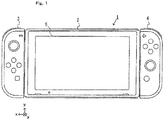
- FIG. 1 is a diagram showing an example external appearance of an information processing system according to an embodiment.
- the information processing system 1 includes a main device 2, a left controller 3, and a right controller 4.
- the main device 2 is an information processing device which executes various processes in the information processing system 1.
- the main device 2 has a display 5.
- the main device 2 has information processing units such as a CPU, a memory, and the like (including a main-device control circuit described below).
- the main device 2 can execute a game process by executing a game program which is stored in its own built-in storage unit or in a storage medium removably attached to the main device 2.
- the left controller 3 and the right controller 4 are an example operation device (also referred to as an "input device") for allowing the use to perform inputting to the information processing system 1.
- the controllers 3 and 4 each have an operation unit (specifically, a button and a stick). Note that the left controller 3 and the right controller 4 may hereinafter be collectively referred to as "the controllers.”
- the controllers may be attached (also referred to as "connected") to the main device 2.
- the left controller 3 may be attached to the left side of the main device 2 (i.e., in the positive direction of an x-axis shown in FIG. 1 from the center of the main device 2).
- the right controller 4 may be attached to the right side of the main device 2 (i.e., in the negative direction of the x-axis shown in FIG. 1 from the center of the main device 2).
- the attached state As shown in FIG 1 , in a state where the controllers are attached to the main device 2 (hereinafter referred to as "the attached state"), the main device 2 and the controllers have a fixed positional relationship therebetween. Therefore, the user can hold the information processing system 1 (i.e., the main device 2 and the controllers) in the attached state as an integrated structure. Therefore, the information processing system 1 can be said to be a portable information processing device (or a game device).
- FIG. 2 is a diagram showing an example external appearance of the information processing system when the controllers are removed from the main device.
- the controllers are removably attached to the main device 2.
- the controllers can be used in a state where the controllers are removed from the main device 2 (hereinafter referred to as "the detached state").
- the detached state the state where the controllers are removed from the main device 2
- the controllers 3 and 4 when the controllers 3 and 4 are attached to the main device 2, the user can hold and use the entire information processing system 1, and in addition, when the controllers 3 and 4 are removed from the main device 2, the user can hold and use the controllers alone.
- the main device 2 can be coupled to a display device not shown (e.g., a television), and can transmit an image to the display device, which then displays the image. Therefore, the user can use the information processing system 1 in such a manner that the user operates the controllers removed from the main device 2 while viewing an image displayed on a display device coupled to the main device 2.
- a display device not shown e.g., a television
- the user can use the information processing system 1 in such a manner that the user operates the controllers removed from the main device 2 while viewing an image displayed on a display device coupled to the main device 2.
- the controllers may be removably attached to the main device 2 by any suitable means.
- a rail member is provided on each of side faces (i.e., side faces in the x-axis direction) of the main device 2, while a slider which is engaged with the rail member so that the slider can be slid with respect to the rail member is provided on a side face of each controller.
- the user can attach the controllers to the main device 2 by engaging the sliders of the controllers with the respective rail members of the main device 2.
- the two controllers 3 and 4 can be simultaneously attached to the main device 2 (see FIG. 1 ).
- any suitable number of controllers may be simultaneously attached to the main device 2.
- the controllers are attached to the side faces of the main device 2.
- the controllers may be attached to other portions of the main device.
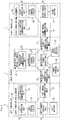
- FIG. 3 is a block diagram showing an example internal configuration of each device (i.e., the main device or the controllers) in the information processing system. Specific example internal configurations of the main device 2 and each of the controllers 3 and 4 will now be described with reference to FIG. 3 .
- the main device 2 has a main-device battery 21 for supplying power to predetermined elements to be supplied with power.
- the elements to be supplied with power are electronic members which are included in the main device 2 and are driven by power (specifically, including various control circuits, a CPU, etc.).
- main-device power-driven elements 25 described below correspond to the elements to be supplied with power.
- the main device 2 has a main-device power supply unit 22 which supplies power from the main-device battery 21 to the above elements to be supplied with power.
- the main-device battery 21 is coupled to the main-device power supply unit 22.
- the main-device power supply unit 22 is coupled to the above predetermined elements to be supplied with power (i.e., the main-device power-driven elements 25 described below).
- the main-device power supply unit 22 supplies power to each of the controllers 3 and 4 under a predetermined condition, in addition to the main-device power-driven elements 25, as described in detail below. Therefore, the main-device power supply unit 22 has a booster circuit for increasing the voltage of power supplied to the controllers to a predetermined voltage (i.e., a voltage which allows charging of a battery in each of the controllers).
- the main device 2 has a main-device control circuit 23 which controls at least a portion of the main device 2.
- the main-device control circuit 23 includes various circuits for controlling the main device 2, such as a CPU and a memory.
- the main-device control circuit 23 also includes a control circuit for controlling a sensor, an input/output unit, and/or a wireless communication unit which are included in the main device 2.
- the main device 2 also has a main-device wireless communication unit 24.
- the main-device wireless communication unit 24 includes an antenna for wireless communication with each of the controllers 3 and 4.
- the main-device wireless communication unit 24 is coupled to the main-device control circuit 23.
- the main-device control circuit 23 and the main-device wireless communication unit 24 are included in the main-device power-driven elements 25.
- the main-device power supply unit 22 supplies power to at least the main-device control circuit 23 and the main-device wireless communication unit 24.
- the main-device power-driven elements 25 include any electronic members such as a sensor (e.g., an acceleration sensor or a gyroscopic sensor) and an input/output unit (e.g., a touchscreen or a display) which are included in the main device 2.
- the main device 2 has a main-device left connection/communication unit 26 which can communicate with the left controller 3 via a wire, and a main-device right connection/communication unit 27 which can communicate with the right controller 4 via a wire.
- the connection/communication units 26 and 27 are each coupled to the main-device power supply unit 22 and the main-device control circuit 23.
- the connection/communication units 26 and 27 each have a plurality of terminals.
- the connection/communication units 26 and 27 each include a communication terminal for transmitting and receiving information, and a power terminal for exchanging power.
- the main-device left connection/communication unit 26 When the main device 2 and the left controller 3 are in the attached state, the main-device left connection/communication unit 26 is connected with a communication unit (a left wired communication unit 37 described below) of the left controller 3. Specifically, in the attached state, the terminals of the main-device left connection/communication unit 26 are in contact with the respective corresponding terminals of the left wired communication unit 37 of the left controller 3. As a result, the main device 2 is electrically connected with the left controller 3. In this regard, the right controller 4 is similar to the left controller 3.
- the main-device right connection/communication unit 27 is connected with the communication unit (a right wired communication unit 47 described below) of the right controller 4, so that the main device 2 is electrically connected with the right controller 4.
- the terminals of the communication units in the main device 2 and the controllers may specifically take any suitable structure.
- each terminal is provided at a position where that terminal is in contact with a respective corresponding terminal when the main device 2 and the controllers are in the attached state.
- the main device 2 has a power terminal unit 28 which can acquire power supplied from a power source external to the main device 2.
- the power terminal unit 28 is a member (e.g., a connector) for electrically connecting a charger not shown (e.g., an AC adaptor, etc.) to the main device 2.
- the power terminal unit 28 may be a USB connector (more specifically, a female connector).
- an AC adaptor can be connected to the power terminal unit 28, and the main device 2 can acquire commercial power supply through the AC adaptor.
- the left controller 3 has a left battery 31 for supplying power to predetermined elements to be supplied with power.
- left power-driven elements 36 described below correspond to the predetermined elements to be supplied with power. Note that, in this embodiment, the capacity of the left battery 31 is smaller than that of the main-device battery 21.
- the left controller 3 has a left power supply unit 32 for supplying power from the left battery 31 to the above elements to be supplied with power.
- the left battery 31 is coupled to the left power supply unit 32.
- the left power supply unit 32 is coupled to the left power-driven elements 36.
- the left power supply unit 32 supplies power (the power of the battery 31 or power supplied from the main device 2) to the above elements to be supplied with power.
- the left power supply unit 32 also charges the left battery 31 with power supplied from the main device 2.
- the left controller 3 has a left control circuit 33, a left wireless communication unit 34, and a left operation unit 35.
- the left control circuit 33 controls at least a portion of the left controller 3, and includes a control circuit for controlling, for example, a sensor (e.g., an acceleration sensor or a gyroscopic sensor) which is included in the left controller 3, the left wireless communication unit 34, and/or the left operation unit 35.
- the left wireless communication unit 34 includes an antenna for wireless communication with the main device 2.
- the left operation unit 35 includes a button and a stick provided on the left controller 3.
- the left control circuit 33, the left wireless communication unit 34, and the left operation unit 35 are included in the left power-driven elements 36.
- the left power supply unit 32 supplies power to at least the left control circuit 33, the left wireless communication unit 34, and the left operation unit 35.
- the left power-driven elements 36 may include any electronic members such as a sensor included in the left controller 3 and the like.
- the left controller 3 has the left wired communication unit 37 which can communicate with the main device 2 via a wire.
- the left wired communication unit 37 is coupled to the left power supply unit 32 and the left control circuit 33.
- the left wired communication unit 37 has as many terminals as there are terminals included in the main-device left connection/communication unit 26 of the main device 2. More specifically, the terminals include a communication terminal for transmitting and receiving information, and a power terminal for exchanging power.
- the right controller 4 has constituent elements 41-47 similar to the constituent elements 31-37 of the left controller 3.
- the right battery 41 corresponds to the left battery 31.
- the right power supply unit 42 corresponds to the left power supply unit 32.
- the right control circuit 43 corresponds to the left control circuit 33.
- the right wireless communication unit 44 corresponds to the left wireless communication unit 34.
- the right operation unit 45 corresponds to the left operation unit 35.
- the right wired communication unit 47 corresponds to the left wired communication unit 37.
- the constituent elements 41-47 of the right controller 4 each have a function similar to that of the respective corresponding one of the constituent elements 31-37 of the left controller 3, and can operate in a similar manner.
- the left controller 3 and the right controller 4 may not have exactly the same configuration and may have different configurations. For example, only one of the left controller 3 and the right controller 4 may have a specific operation unit and/or sensor. The left controller 3 and the right controller 4 may have different external appearances, or different arrangements of the constituent elements (e.g., a button and a stick).
- the left controller 3 transmits controller information to the main device 2 at a rate of once per predetermined period of time.
- the controller information includes operation information indicating an operation performed on an operation unit (i.e., the left operation unit 35), and remaining charge amount information indicating the amount of charge remaining in the left battery 31.
- remaining charge amount information about a battery is any information that can be used to estimate (or calculate) or determine the amount of charge remaining in the battery.
- the remaining charge amount information about a battery may be voltage information indicating the voltage of the battery, or information indicating the value of a proportion (e.g., a percentage or a fraction) indicating the amount of charge remaining in the battery, which is calculated from the voltage information.
- the left power supply unit 32 repeatedly acquires the remaining charge amount information about the left battery 31, and outputs the acquired remaining charge amount information to the left control circuit 33.
- the left control circuit 33 repeatedly transmits the controller information including the operation information and the remaining charge amount information to the main device 2.
- the main device 2 transmits instruction information to the left controller 3.
- the instruction information which indicates an instruction to the left controller 3, includes information indicating whether or not the left battery 31 is to be charged.
- the instruction information may be transmitted from the main device 2 to the left controller 3 with any suitable timing.
- the instruction information is transmitted at the same intervals at which the controller information is transmitted (i.e., once per the above predetermined period of time), or at intervals different from those of the controller information.
- the main device 2 and the left controller 3 can perform wired communication through the above terminals, or wireless communication using the wireless communication units.
- the main device 2 and the left controller 3 perform wired communication.
- the main-device left connection/communication unit 26 of the main device 2 is electrically connected with the left wired communication unit 37 of the left controller 3 so that wired communication can be performed therebetween. Therefore, the left control circuit 33 transmits the controller information (in other words, the remaining charge amount information included in the controller information) to the main device 2 by wired communication through the left wired communication unit 37.
- the main-device control circuit 23 transmits the instruction information to the left controller 3 through the main-device left connection/communication unit 26.
- one of the main device 2 and the left controller 3 can transmit information to the other by wired communication (i.e., without using wireless communication).
- the main device 2 and the left controller 3 perform wireless communication.
- the left control circuit 33 transmits the controller information to the main device 2 by wireless communication through the left wireless communication unit 34 (in other words, the left control circuit 33 causes the left wireless communication unit 34 to transmit the controller information).
- the main-device control circuit 23 transmits the instruction information to the left controller 3 through the main-device wireless communication unit 24 (in other words, the main-device control circuit 23 causes the main-device wireless communication unit 24 to transmit the instruction information).
- the main-device control circuit 23 causes the main-device wireless communication unit 24 to transmit the instruction information.
- the main device 2 and the controllers may perform communication wirelessly no matter whether they are in the attached state or in the detached state.
- the main device 2 and the controllers may perform wireless communication at least in the detached state, and may also perform wireless communication in the attached state.
- the controllers may be used only in the attached state. In other words, the controllers may not have the function of wirelessly communicating with the main device 2.
- the main device 2 notifies the user of the amount of charge remaining in each of the batteries 31 and 41 of the controllers 3 and 4.
- the main device 2 may display, on the display 5, information indicating the amount of charge remaining in each of the batteries 31 and 41.
- the main device 2 can acquire the remaining charge amount information in both the attached state and the detached state, and therefore, in both of the two states, can notify the user of the amount of remaining charge.
- the main device 2 and the controllers are each provided with a battery. Therefore, the main device 2 and the controllers can each be driven by power from their own built-in batteries.
- the main device 2 supplies power to the controllers under a predetermined condition so that the duration in which the information processing system 1 can be used is extended. As a result, the duration in which the controllers can be used can be extended, and therefore, the duration in which the information processing system 1 can be used can be extended.
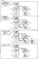
- FIG. 4 is a diagram showing example ways of supplying power to the left-controller power-driven elements.
- the information processing system 1 determines the way of supplying power to the left power-driven elements 36, depending on which of modes (a)-(d) shown in FIG. 4 the information processing system 1 is in. The way of supplying power in each of modes (a)-(d) shown in FIG. 4 will be described.
- mode (a) shown in FIG. 4 the main device 2 and the left controller 3 are in the attached state, the main device 2 is not supplied with power from an external power source, and the amount of charge remaining in the left battery 31 is sufficient.
- it is determined whether or not the amount of charge remaining in the left battery 31 is sufficient by a determination step of determining whether or not the amount of charge remaining in the left battery 31 is greater than or equal to a predetermined threshold value.
- the main device 2 can determine the amount of charge remaining in the left battery 31 on the basis of the remaining charge amount information transmitted from the left controller 3.
- the predetermined threshold value used in the determination step one of two different threshold values is used, depending on whether or not the left controller 3 is being supplied with power, as described in detail below.
- the main-device power supply unit 22 does not supply power to the left controller 3.
- the left power supply unit 32 supplies power from the left battery 31 to the left power-driven elements 36 (indicated by a dashed arrow shown in a portion corresponding mode (a) of FIG. 4 ).
- the main-device power supply unit 22 supplies power to the main-device power-driven elements 25, although not shown in FIG. 4 .
- the main-device power supply unit 22 when the main-device power supply unit 22 is supplying power to the left controller 3, the main-device power supply unit 22 is supplying power to the main-device power-driven elements 25 as well as the left controller 3.
- the main-device power supply unit 22 supplies power from the main-device battery 21 to the main-device power-driven elements 25.
- mode (b) shown in FIG. 4 the main device 2 and the left controller 3 are in the attached state, the main device 2 is not supplied with power from an external power source, and the amount of charge remaining in the left battery 31 is not sufficient.
- the main-device power supply unit 22 supplies power in mode (a) shown in FIG. 4 if the amount of charge remaining in the left battery 31 is sufficient, or in mode (b) shown in FIG. 4 if the amount of charge remaining in the left battery 31 is not sufficient.
- the main-device power supply unit 22 supplies power from the main-device battery 21 to the left controller 3 (specifically, the left power-driven elements 36) (indicated by a dashed arrow shown in a portion corresponding mode (b) of FIG. 4 ).
- the left power supply unit 32 supplies power supplied from the main device 2 to the left power-driven elements 36.
- the main device 2 charges the left controller 3. Specifically, the left power supply unit 32 charges the left battery 31 with power supplied from the main device 2 (indicated by a dashed arrow shown in a portion corresponding to mode (b) of FIG. 4 ).
- the main-device power supply unit 22 supplies power from the main-device battery 21 to the main-device power-driven elements 25, as in mode (a) of FIG. 4 .
- mode (b) shown in FIG. 4 when the left battery 31 is charged, so that the amount of charge remaining in the left battery 31 is greater than or equal to a predetermined value, the main device 2 determines that the amount of charge remaining in the left battery 31 is sufficient, as described in detail below. As a result, the information processing system 1 is changed from mode (b) to mode (a) shown in FIG. 4 , in which the charging of the left battery 31 is stopped.
- the main-device power supply unit 22 supplies power from the main-device battery 21 to the left controller 3 under a predetermined condition about the amount of remaining charge which is indicated by the remaining charge amount information received from the left controller 3 (specifically, the amount of remaining charge is smaller than the predetermined threshold value).
- the left power supply unit 32 supplies power supplied from the main device 2 to the left power-driven elements 36 (including the left control circuit 33) instead of power from the left battery 31.
- the main device 2 does not always supply power to the left controller 3 when the left controller 3 is in the attached state, and supplies power under a predetermined condition about the amount of charge remaining in the left battery 31. Therefore, the power of the main-device battery 21 can be efficiently used. As a result, the duration in which the information processing system 1 can be used can be extended.
- the main device 2 supplies power to the left controller 3. Therefore, the occurrence of the situation where the battery of the left controller 3 is dead can be reduced.
- the user can charge the left battery 31 by attaching the left controller 3 to the main device 2. In other words, even when the amount of charge remaining in the left battery 31 is zero, the user can use the left controller 3 to operate the main device 2 by attaching the left controller 3 to the main device 2.
- mode (c) shown in FIG. 4 the main device 2 and the left controller 3 are in attached state, and the main device 2 is being supplied with power from an external power source.
- mode (c) shown in FIG. 4 the main device 2 is being supplied with power from an external power source, i.e. external power is being supplied to the main device 2 through the power terminal unit 28.
- the main-device power supply unit 22 supplies external power from the power terminal unit 28 to the left controller 3 (indicated by a dashed arrow shown in a portion corresponding to mode (c) of FIG. 4 ).
- the left power supply unit 32 supplies power supplied from the main device 2 to the left power-driven elements 36, and at the same time, charges the left battery 31 with power supplied from the main device 2 (indicated by dashed arrows shown in the portion corresponding to mode (b) of FIG. 4 ).
- the main-device power supply unit 22 supplies external power from the power terminal unit 28 to the main-device power-driven elements 25 (not shown), and at the same time, charges the main-device battery 21 with external power from the power terminal unit 28 (indicated by a dashed arrow shown in the portion corresponding to mode (c) of FIG. 4 ).
- the main-device power supply unit 22 may not charge the main-device battery 21 when the amount of charge remaining in the main-device battery 21 is greater than or equal to a predetermined value.
- the main-device power supply unit 22 charges the main-device battery 21 until the main-device battery 21 reaches a full charge (i.e., the amount of remaining charge is 100%).
- the left power supply unit 32 charges the left battery 31 until the amount of charge remaining in the left battery 31 is 100%. Therefore, in mode (c) shown in FIG. 4 , the information processing system 1 can sufficiently charge the batteries 21 and 31.
- the main-device power supply unit 22 when supplied with power from a power source external to the main device 2 through the power terminal unit 28, supplies power supplied from the power source external to the main device 2 to the main-device power-driven elements 25.
- the main-device power supply unit 22 may supply power supplied from a power source external to the main device 2 to the left controller 3, regardless of the amount of remaining charge indicated by the remaining charge amount information.
- the main device 2 and the left controller 3 are in the detached state (i.e., the left controller 3 wirelessly communicates with the main device 2).
- the main device 2 is not connected with the left controller 3 via a wire, and therefore, the main-device power supply unit 22 does not supply power to the left controller 3 (see a portion corresponding to mode (d) of FIG. 4 ). Therefore, when the left controller 3 is wirelessly communicating with the main device 2, the left power supply unit 32 supplies power from the left battery 31 to the left power-driven elements 36 (indicated by a dashed arrow shown in the portion corresponding to mode (d) of FIG. 4 ). As a result, the left controller 3 can operate even in the detached state.
- the main device 2 determines not to supply power to the left controller 3. Meanwhile, if the amount of charge remaining in the left battery 31 is smaller than the threshold value, the main device 2 determines to supply power to the left controller 3.
- the determination of whether or not to supply to the left controller 3 is based on a first threshold value and a second threshold value smaller than the first threshold value. The determination step will now be described in greater detail with reference to FIG 5 , which shows a non-limiting example.
- FIG. 5 is a diagram showing example changes with time in the amount of charge remaining in the left battery 31 coupled to the main device 2.
- the main device 2 initially performs the determination using the first threshold value at a time point T0 when the left controller 3 is attached to the main device 2 (referred to as "the attachment time point").
- the main-device control circuit 23 when detecting the attachment of the left controller 3 to the main device 2, determines whether or not the amount of remaining charge indicated by the remaining charge amount information from the left controller 3 is greater than or equal to the first threshold value. If the amount of remaining charge indicated by the remaining charge amount information from the left controller 3 is greater than or equal to the first threshold value, the main-device control circuit 23 determines not to supply power to the left controller 3.
- the main-device control circuit 23 determines to supply power to the left controller 3. Note that it is here assumed that the amount of charge remaining in the battery is expressed in percentage terms, and the first threshold value is 50%.
- the second threshold value in the determination step at the time of the attachment, the second threshold value, or a threshold value which is different from the first and second threshold values (e.g., a value which is smaller than the first threshold value and greater than the second threshold value), may be used.
- the main-device control circuit 23 determines not to supply power.
- the main-device control circuit 23 causes the main-device power supply unit 22 to operate in mode (a) shown in FIG. 4 .
- the left power-driven elements 36 are driven by power from the left battery 31, and therefore, the amount of charge remaining in the left battery 31 decreases with time (see FIG 5 ).
- the main-device control circuit 23 determines to supply power, although not shown. In this case, the main-device control circuit 23 causes the main-device power supply unit 22 to operate in mode (b) shown in FIG. 4 .
- the determination step is performed at a rate of once per predetermined period of time.
- the determination step is, for example, performed each time the controller information is acquired from the left controller 3.
- the main-device control circuit 23 performs the determination step using the first threshold value when power is being supplied to the left controller 3, and the second threshold value when power is not being supplied to the left controller 3.
- the determination step is performed using the second threshold value immediately after the attachment time point T0.
- the second threshold value is 25%, which is smaller than the first threshold value. Therefore, as in the example shown in FIG. 5 , when power is not being supplied, then if the amount of charge remaining in the left battery 31 is smaller than the first threshold value, but greater than or equal to the second threshold value, power is not supplied to the left controller 3.
- the main-device control circuit 23 determines to supply power to the left controller 3. As a result, power starts to be supplied from the main device 2 to the left controller 3, so that the left battery 31 is charged (see the portion corresponding to mode (b) of FIG 4 ). Therefore, after the time point T1, the amount of charge remaining in the left battery 31 increases with time (see FIG 5 ).
- the main-device control circuit 23 determines not to supply power to the left controller 3. As a result, the main device 2 stops supplying power to the left controller 3. Therefore, after the time point T2, the amount of charge remaining in the left battery 31 decreases with time (see FIG. 5 ).
- the main device 2 after the time point T2, the main device 2 repeatedly performs an operation of starting supplying power to the left controller 3 when the amount of charge remaining in the left battery 31 becomes smaller than the second threshold value, and an operation of stopping supplying power to the left controller 3 when the amount of charge remaining in the left battery 31 becomes greater than or equal to the first threshold value. Therefore, in this embodiment, in the attached state, the amount of charge remaining in the left battery 31 is maintained greater than or equal to the second threshold value (here 25%).
- the left controller 3 when power is being supplied from the left battery 31 to the left control circuit 33, then if the main device 2 starts supplying power to the left controller 3 (the time point T1 shown in FIG. 5 ), the left power supply unit 32 stops supplying power from the left battery 31 to the left control circuit 33, and starts supplying power supplied from the main device 2 to the left control circuit 33. Therefore, in this embodiment, the left controller 3 can inhibit power consumption of its own left battery 31 when power is supplied from the main device 2.
- the main-device power supply unit 22 when the main-device power supply unit 22 is supplying power to the left controller 3, then if the amount of remaining charge indicated by the remaining charge amount information transmitted from the left controller 3 becomes greater than or equal to the first threshold value, the main-device power supply unit 22 stops supplying power to the left controller 3 (the time point T2 shown in FIG. 5 ).
- the main-device power supply unit 22 When the main-device power supply unit 22 is not supplying power to the left controller 3, then if the amount of remaining charge indicated by the remaining charge amount information transmitted from the left controller 3 becomes smaller than the second threshold value, the main-device power supply unit 22 starts supplying power to the left controller 3 (the time point T1 shown in FIG. 5 ).
- the main device 2 determines whether or not to supply power to the left controller 3 on the basis of the determination step, regardless of the amount of charge remaining in the main-device battery 21. In other words, in this embodiment, even when the amount of charge remaining in the main-device battery 21 is small, the main device 2 may supply power to the left controller 3. In this embodiment, when the information processing system 1 continues to be used in the attached state, the amount of charge remaining in the main-device battery 21 reaches zero earlier than does the amount of charge remaining in each controller.
- the controller can no longer be used in the detached state. In this case, while the main device 2 can operate, the controller cannot be used, and therefore, the user cannot use the information processing system 1.
- the user can use the controllers in the detached state while the main device 2 is being charged (e.g., the main device 2 may be coupled to a display device, which is used to display an image, as described above).
- the possibility that the amount of charge remaining in the battery of a controller reaches zero earlier is reduced, and therefore, even after the amount of charge remaining in the main-device battery 21 reaches zero, the controllers can be used, leading to an improvement in the convenience of the information processing system 1.
- the main device 2 supplies power to the left controller 3 in a manner similar to that described above.
- the main device 2 controls power supply to the controllers 3 and 4 separately.
- the main device 2 determines whether or not to supply power to the right controller 4 no matter what state the left battery 31 is in (e.g., the attached state, or the state of charge of the left battery 31). Therefore, the main device 2 may not supply power to the right controller 4 while supplying power to the left controller 3.
- the main-device power supply unit 22 supplies power from the main-device battery 21 to one or more of a plurality of controllers (two in this embodiment) attached to the main device 2 that have transmitted the remaining charge amount information satisfying a condition (i.e., the remaining charge amount information indicating that the amount of remaining charge is smaller than a threshold value).
- a condition i.e., the remaining charge amount information indicating that the amount of remaining charge is smaller than a threshold value.
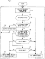
- FIG 6 is a flowchart showing an example flow of a process executed in the main device 2. Note that a series of steps shown in FIG. 6 is continually executed when the main device 2 is active. Specifically, the series of steps shown in FIG 6 is started during activation of the main device 2.
- the main device 2 operates in either an on mode or a sleep mode when it is active. In the on mode, for example, the main device 2 performs a normal operation. In the sleep mode, for example, the display may be off, or no application may be executed.
- the series of steps is executed in each of the two modes. Note that, in another embodiment, the series of steps may not be executed in the sleep mode.
- a CPU included in the main-device control circuit 23 of the main device 2 executes each step shown in FIG 6 .
- the CPU executes each step shown in FIG. 6 by executing an information processing program stored in the main device 2.
- a portion of the steps in the flowchart may be executed by a processor or a dedicated circuit (e.g., a circuit included in the main-device power supply unit 22) other than the CPU.
- step S1-S9 steps S1-S9 with respect to the left controller 3, and the series of steps with respect to the right controller 4, are executed in parallel.
- the main device 2 stores, in a memory, various pieces of information (in other words, data) which are used in the series of steps shown in FIG. 6 .
- the memory stores the remaining charge amount information, the first threshold value information, the second threshold value information, and the power supply flag information.
- the first threshold value information indicates the first threshold value.
- the second threshold value information indicates the second threshold value.
- the power supply flag information indicates a flag which indicates whether or not the main device is supplying power to a controller.
- the power supply flag information about the left controller 3 and the power supply flag information about the right controller 4 are stored in a memory.
- the main-device control circuit 23 (specifically, a CPU) executes each step shown in FIG. 6 using the memory. Specifically, the main-device control circuit 23 stores information obtained in each step into the memory, and reads and uses the information from the memory in a subsequent step if necessary.
- step S2 the main-device control circuit 23 determines whether or not the main device 2 and the left controller 3 are in the attached state.
- the determination in step S2 may be specifically achieved in any suitable manner.
- the main-device control circuit 23 performs the determination on the basis of a signal state (e.g., a voltage state) at a predetermined terminal included in the main-device left connection/communication unit 26. If the determination result in step S2 is positive, step S3 is executed. Meanwhile, if the determination result in step S2 is negative, step S9 is executed.
- a signal state e.g., a voltage state
- step S3 the main-device control circuit 23 determines whether or not the main device 2 is being supplied with power from an external power source. Specifically, the main-device control circuit 23 determines whether or not power is being supplied from an external power source through the power terminal unit 28. If the determination result in step S3 is positive, step S4 is executed. Meanwhile, if the determination result in step S3 is negative, step S5 is executed.
- step S4 the main-device control circuit 23 supplies external power to the left controller 3. Specifically, the main-device control circuit 23 outputs a control instruction to the main-device power supply unit 22 to supply external power from the power terminal unit 28 to the left controller 3. Note that if external power has already been being supplied to the left controller 3 at step S4, the main-device control circuit 23 may not output the control instruction again.
- the main-device control circuit 23 also transmits instruction information indicating an instruction to charge the left battery 31, to the left controller 3 through the main-device left connection/communication unit 26.
- step S4 the main-device control circuit 23 supplies external power from the power terminal unit 28 to the main-device power-driven elements 25, and controls the main-device power supply unit 22 so that the main-device battery 21 is charged using external power from the power terminal unit 28.
- mode (c) shown in FIG. 4 is performed by step S4.
- step S1 is executed again.
- step S5 the main-device control circuit 23 determines whether or not either "the left controller 3 has been just attached to the main device 2 (in other words, it is immediately after the attachment)" or "the left controller 3 is being supplied with power.”
- it can be determined whether or not the left controller 3 has been just attached to the main device 2, by determining whether or not the determination result in step S2 has just changed from negative to positive, for example. It can be determined whether or not the left controller 3 is being supplied with power, by referring to the power supply flag information stored in the memory. If the determination result in step S5 is positive, step S6 is executed. Meanwhile, if the determination result in step S5 is negative, step S7 is executed.
- step S6 the main-device control circuit 23 determines whether or not the amount of charge remaining in the left battery 31 is sufficient, using the first threshold value. Specifically, the main-device control circuit 23 determines whether or not the amount of charge remaining in the left battery 31 which is indicated by the remaining charge amount information acquired in step S1 is greater than or equal to 50%. If the determination result in step S6 is positive, step S9 is executed. Meanwhile, if the determination result in step S6 is negative, step S8 is executed.
- step S7 it is determined whether or not the amount of charge remaining in the left battery 31 is sufficient, using the second threshold value. Specifically, the main-device control circuit 23 determines whether or not the amount of charge remaining in the left battery 31 which is indicated by the remaining charge amount information acquired in step S1 is greater than or equal to 25%. If the determination result in step S7 is positive, step S9 is executed. Meanwhile, if the determination result in step S7 is negative, step S8 is executed.
- step S8 the main-device control circuit 23 controls the main-device power supply unit 22 so that power is supplied from the main-device battery 21 to the main-device power-driven elements 25.
- step S8 the operation of mode (b) shown in FIG. 4 is performed.
- step S1 is executed again.
- step S9 the main-device control circuit 23 supplies power to the main-device power-driven elements 25, but not to the left controller 3. Specifically, the main-device control circuit 23 controls the main-device power supply unit 22 so that power is supplied from the main-device battery 21 to the main-device power-driven elements 25. The main-device control circuit 23 also stores, into the memory, the power supply flag information indicating that power is not being supplied to the left controller 3. Note that, at the time of step S9, if power is not being supplied from the main-device battery 21 to the left controller 3, the main-device control circuit 23 may not store the power supply flag information into the memory.
- the main-device control circuit 23 also transmits instruction information indicating an instruction not to charge the left battery 31, to the left controller 3 through the main-device left connection/communication unit 26.
- step S9 the operation of mode (a) or (d) shown in FIG. 4 is performed.
- step S1 is executed again.
- FIG. 7 is a flowchart showing an example flow of a process executed in the left controller 3. Note that a series of steps shown in FIG. 7 is continually executed when the left controller 3 is active (specifically, when power is being supplied to the left power-driven elements 36, or when the left controller 3 is on).
- the left control circuit 33 of the left controller 3 executes each step shown in FIG. 7 .
- a portion of the steps in the flowchart may be executed by another processing circuit (e.g., a circuit included in the left power supply unit 32) instead of the left control circuit 33.
- FIG. 7 a series of steps executed by the left controller 3 is shown. Note that, in this embodiment, the right controller 4 executes a series of steps similar to those shown in FIG. 7 .
- the left controller 3 stores, in its own built-in memory, various pieces of information (in other words, data) for use in the series of steps shown in FIG. 7 .
- the left control circuit 33 executes each step shown in FIG. 7 using the memory. Specifically, the left control circuit 33 stores information obtained in each step into the memory, and reads and uses the information from the memory in a subsequent step if necessary.
- step S11 shown in FIG. 7 the left control circuit 33 communicates with the main device 2. Specifically, the left control circuit 33 transmits the controller information to the main device 2 through the left wireless communication unit 34 or the left wired communication unit 37. The left control circuit 33 receives the instruction information from the main device 2 through the left wireless communication unit 34 or the left wired communication unit 37. Note that, in this embodiment, step S11 is repeatedly executed at a rate of once per predetermined period of time. Following step S11, step S12 is executed.
- step S12 the left control circuit 33 determines whether or not the main device 2 and the left controller 3 are in the attached state.
- the determination in step S12 may be specifically achieved in any suitable manner.
- the left control circuit 33 performs the determination on the basis of a signal state (e.g., a voltage state) at a predetermined terminal included in the left wired communication unit 37. If the determination result in step S12 is positive, step S13 is executed. Meanwhile, if the determination result in step S12 is negative, step S15 is executed.
- a signal state e.g., a voltage state
- step S13 the left control circuit 33 determines whether or not power is being supplied from the main device 2 through the left wired communication unit 37.
- the determination in step S13 may be specifically achieved in any suitable manner.
- the left control circuit 33 may perform the determination on the basis of whether or not the instruction information transmitted from the main device 2 indicates an instruction to charge the left battery 31, or on the basis of the voltage state of the power terminal included in the left wired communication unit 37. If the determination result in step S13 is positive, step S14 is executed. Meanwhile, if the determination result in step S13 is negative, step S15 is executed.
- step S14 the left control circuit 33 supplies power from the main device 2 to the left power-driven elements 36, and charges the left battery 31 with power from the main device 2. Specifically, the left control circuit 33 controls the left power supply unit 32 so that power is supplied from the main device 2 to the left power-driven elements 36, and at the same time, the left battery 31 is charged with power from the main device 2 (modes (b) and (c) shown in FIG. 4 ).
- step S11 is executed again.
- step S15 the left control circuit 33 supplies power from the left battery 31 to the left power-driven elements 36. Specifically, the left control circuit 33 controls the left power supply unit 32 so that power is supplied from the left battery 31 to the left power-driven elements 36 (modes (a) or (d) shown in FIG. 4 ). Following step S15, step S11 is executed again.
- the power supply unit (specifically, the left power supply unit 32 or the right power supply unit 42) of each of the controllers 3 and 4, when the controller is supplied with power from the main device 2, supplies power supplied from the main device 2 to the control circuit (specifically, the left control circuit 33 or the right control circuit 43), and at the same time, charges the battery (specifically, the left battery 31 or the right battery 41) with power supplied from the main device 2.
- the power supply unit of each of the controllers 3 and 4 when the controller is supplied with power from the main device 2, may supply the supplied power to the control circuit, and at the same time, may not charge the battery.
- the main device 2 when supplying power to a controller, may supply power to elements of the controller which are to be supplied with power, and at the same time, may not charge the battery of the controller.
- the main device 2 when supplying power to a controller, can supply power only to elements to be supplied with power by transmitting, to the controller, the instruction information indicating an instruction not to charge the battery of the controller.
- the main device 2 when power is not being supplied to a controller, then if the amount of charge remaining in the controller is smaller than a predetermined threshold value, the main device 2 may supply power only to elements of the controller which are to be supplied with power (i.e., may not charge the battery). As a result, the rate of decrease of the amount of charge remaining in the main-device battery 21 of the main device 2 can be reduced, and therefore, the duration in which the main device 2 can be used can be extended.
- the predetermined threshold value in this variation may be, for example, the first threshold value or the second threshold value.
- the main device 2 may use a single threshold value.
- the main device 2 when a controller is attached to the main device 2, then if the amount of charge remaining in the battery of the controller is smaller than the predetermined threshold value, power may be supplied to elements of the controller which are to be supplied with power, and the battery of the controller may be charged.
- the main device 2 when a predetermined first condition is satisfied, the main device 2 may supply power to elements of the controller which are to be supplied with power, and charge the battery of the controller.
- the main device 2 may only supply power to elements of the controller which are to be supplied with power.
- the first and second conditions are, for example, a condition about the amount of charge remaining in a controller, a condition about the state of power supply from the main device 2 to a controller (e.g., whether or not power is being supplied), and/or the attached state of the main device 2 and a controller (e.g., whether or not the main device 2 and the controller have been just attached together).
- the main device 2 may stop supplying power to the controllers. Specifically, when the amount of charge remaining in the main-device battery 21 becomes smaller than or equal to a predetermined value (e.g., 25% or less), the main-device power supply unit 22 may stop supplying power from the main-device battery 21 to the controllers, regardless of the amount of remaining charge indicated by the remaining charge amount information transmitted from the controllers. As a result, a decrease in the amount of charge remaining in the main-device battery 21 of the main device 2 can be reduced, and therefore, the duration in which the main device 2 can be used can be extended.
- a predetermined value e.g. 25% or less
- a variation in which power is supplied only to elements of a controller which are to be supplied with power (see the above section "(Variation of Charging of Battery of Controller)"), and a variation in which power supply to the controllers is stopped when the amount of charge remaining in the main-device battery 21 is small (see the above section “(Variation of Power Supply to Controller)”), may be combined together.
- the main device 2 may start supplying power to a controller in response to the attachment of the controller to the main device 2.
- the main device 2 may stop supplying power to the controller under a predetermined condition (e.g., when the amount of charge remaining in the controller is greater than or equal to a predetermined value), or may continue to supply power to the controller as long as the controller is in the attached state.
- the controller may only supply power supplied from the main device 2 to elements of the controller which are to be supplied with power, or may supply power to elements of the controller which are to be supplied with power, and charge the battery.
- the main-device power supply unit 22 supplies power from the main-device battery 21 to the controller which is allowed to perform wired communication with the main device 2 (in other words, the controller is connected witth the main device 2 by wired communication).
- the power supply units 32 and 42 of the controllers 3 and 4 supply power from the batteries 31 and 41 of the controllers 3 and 4 to the control circuits 33 and 43, respectively.
- the controllers can be used in the detached state from the main device 2, and the batteries of the controllers can be charged by being attached to the main device 2, and therefore, the user can use the controller while the controllers are being charged. As a result, the convenience of the controllers can be improved.
- the main-device control circuit 23 executes a game process on the basis of operations performed on the operation unit (the left operation unit 35 and/or the right operation unit 45).
- the information processing system 1 functions as a game device (or a game system).
- the information processing system 1 may be, for example, any information processing devices such as a tablet terminal, smartphone, mobile telephone, and the like, in addition to a game device.
- the process operations of the main device 2 and/or the controllers may be changed by the main device 2 receiving an update instruction from the server.
- the main device 2 may change (a) the threshold value, (b) whether or not the battery of a controller is to be charged when power is supplied to the controller, or (c) whether or not power is to be supplied to a controller when the amount of charge remaining in the main-device battery 21 is small.
- a portion of the steps which are executed in the main device 2 in the above embodiments may be executed in the controllers.
- a portion of the steps which are executed in the controllers in the above embodiments may be executed in the main device 2.
- the controllers may execute the determination steps using the threshold values (i.e., the determination steps in steps S6 and S7), and transmit the determination results to the main device 2.
- the controller may determine whether or not the battery of the controller is to be charged.
- the above embodiments may be applied to a mobile information processing device (or information processing system), game device (or game system), and the like, in order to improve the convenience of an operation device, for example.
Landscapes
- Engineering & Computer Science (AREA)
- Multimedia (AREA)
- Theoretical Computer Science (AREA)
- Human Computer Interaction (AREA)
- General Engineering & Computer Science (AREA)
- Computer Hardware Design (AREA)
- Physics & Mathematics (AREA)
- General Physics & Mathematics (AREA)
- Computer Networks & Wireless Communication (AREA)
- Power Engineering (AREA)
- Charge And Discharge Circuits For Batteries Or The Like (AREA)
- Power Sources (AREA)
- Remote Monitoring And Control Of Power-Distribution Networks (AREA)
Description
- The present invention relates to a power supply method of an information processing system which includes an information processing device and an operation device attachable to the information processing device.
- An information processing system including a main device and an operation device is known (see, for example, Japanese Laid-Open Patent Publication No.
2005-012526 - When the operation device is connected with the main device via a wire, the range within which the operation device can be used is limited, which is inconvenient. When the operation device and the main device are wirelessly communicating with each other, then if the battery in the operation device becomes dead, the operation device can no longer be used. Therefore, it is desirable to maintain the power of the battery in the operation device as long as possible.
-
US 2003/030412 A1 shows a USB host that charges a client device over a USB connection. When the client device is fully charged, charging is stopped. A battery level of the client device is transmitted to the host at least in the event that the client battery is fully charged. Additionally,US 2013/232350 A1 discloses a transmission of a battery level to a host device. - With the above in mind, it is an object of the present invention to improve the convenience of an operation device.
- To achieve the object, the present invention employs the following configurations (1) to (12).
- (1) An example of the present invention is an information processing system which includes a main device, and an operation device attachable to the main device.
The operation device includes a first control circuit, a first battery, first power supply means, and remaining charge amount information transmission means. The first control circuit controls at least a portion of the operation device. The first battery supplies power to the first control circuit. The first power supply means allows power supply from the first battery to the first control circuit. The remaining charge amount information transmission means transmits, to the main device, remaining charge amount information indicating the amount of charge remaining in the first battery.
The main device includes a second control circuit, a second battery, and second power supply means. The second control circuit controls at least a portion of the main device. The second battery supplies power to the second control circuit. The second power supply means allows power supply from the second battery to the second control circuit.
The second power supply means supplies power from the second battery to the operation device in response to satisfaction of a condition about the amount of remaining charge indicated by the remaining charge amount information transmitted from the remaining charge amount information transmission means. When power is supplied from the main device to the operation device, the first power supply means supplies power supplied from the main device to the first control circuit, instead of power from the first battery.
The operation device further includes an operation unit, the remaining charge amount information transmission means includes a third communication unit for allowing wireless communication with the main device, the main device further includes a fourth communication unit for allowing wireless communication with the operation device, and the remaining charge amount information transmission means transmits operation information indicating an operation performed on the operation unit, and the remaining charge amount information, to the main device by the wireless communication through the third communication unit; wherein when the main device is not supplied with power from an external power source, and power is supplied from the main device to the operation device, the first power supply means supplies power supplied from the main device to the first control circuit, and charges the first battery using power supplied from the main device.
According to the configuration (1), power is supplied from the main device to the operation device in response to satisfaction of the condition about the amount of charge remaining in the first battery. Therefore, the occurrence of the situation where the amount of charge remaining in the first battery of the operation device becomes zero, so that the operation device can no longer be used, can be reduced. Thus, the convenience of the operation device can be improved. In addition, the main device does not always supply power to the operation device when the operation device is in the connected state, and supplies power in response to satisfaction of the condition about the amount of charge remaining in the first battery. Therefore, the power of the second battery of the main device can be efficiently used. As a result, the duration in which the information processing system can be used can be extended. Thus, the convenience of the operation device and the information processing system can be improved. - (2) The operation device may further include an operation unit. The remaining charge amount information transmission means may include a first communication unit for allowing wired communication with the main device. The main device may further include a second communication unit for allowing wired communication with the operation device. The remaining charge amount information transmission means may transmit operation information indicating an operation performed on the operation unit, and the remaining charge amount information, to the main device by the wired communication through the first communication unit. The second power supply means, when determining to supply power to the operation device, may supply power from the second battery to the operation device through the second communication unit.
According to the configuration (2), power supply is performed through the communication units which perform wired communication between the main device and the operation device, and the remaining charge amount information is transmitted through the communication units. As a result, the main device can acquire the remaining charge amount information from the operation device without using wireless communication. - (3) The operation device may further include an operation unit. The remaining charge amount information transmission means may include a third communication unit for allowing wireless communication with the main device. The main device may further include a fourth communication unit for allowing wireless communication with the operation device. The remaining charge amount information transmission means may transmit operation information indicating an operation performed on the operation unit, and the remaining charge amount information, to the main device by the wireless communication through the third communication unit.
According to the configuration (3), the operation device can transmit information to the main device by the wireless communication. The user can use the operation device in the detached state. Therefore, the configuration (3) can further improve the convenience of the operation device. - (4) When the operation device is performing the wireless communication with the main device, the first power supply means may supply power from the first battery to the first control circuit.
According to the configuration (4), the operation device, when performing the wireless communication, can be driven by power from its own built-in battery, i.e. the first battery. - (5) The main device may further include a power terminal for allowing acquisition of power supplied from a power source external to the main device. When the second power supply means is supplied with power from the power source through the power terminal, the second power supply means may supply power supplied from the power source to the second control circuit, and supply power supplied from the power source to the operation device.
According to the configuration (5), when external power is supplied to the main device, the information processing system can be driven without consumption of power of the second battery of the main device. - (6) When the first power supply means is supplying power from the first battery to the first control circuit, then if power is supplied from the main device to the operation device, the first power supply means may stop supplying power from the first battery to the first control circuit, and start supplying power supplied from the main device to the first control circuit.
According to the configuration (6), the operation device, when supplied with power from the main device, can reduce power consumption of its own built-in battery, i.e. the first battery. - (7) When power is supplied from the main device to the operation device, the first power supply means may supply power supplied from the main device to the first control circuit, and charge the first battery using power supplied from the main device.
According to the configuration (7), when power is supplied from the main device to the operation device, the operation device can charge its own built-in battery, i.e. the first battery. As a result, the user can use the operation device while the operation device is being charged, and therefore, the convenience of the operation device can be improved. - (8) When the second power supply means is supplying power to the operation device, then if the amount of remaining charge indicated by the remaining charge amount information transmitted from the remaining charge amount information transmission means is greater than or equal to a first value, the second power supply means may stop supplying power to the operation device. When the second power supply means is not supplying power to the operation device, then if the amount of remaining charge indicated by the remaining charge amount information transmitted from the remaining charge amount information transmission means is smaller than a second value which is smaller than the first value, the second power supply means may start supplying power to the operation device.
According to the configuration (8), the main device determines whether or not to supply power from the main device to the operation device, using different values depending on whether or not power is being supplied from the main device to the operation device. Thus, by using such different values, the frequency of repetition of the starting and stopping of power supply can be reduced. - (9) In the information processing system, there may be a plurality of the operation devices attachable to the main device. The second power supply means may supply power from the second battery to any operation device that has transmitted the remaining charge amount information satisfying the condition, of the plurality of operation devices attached to the main device.
According to the configuration (9), a plurality of operation devices can be simultaneously attached to the main device. Therefore, the convenience of the operation device can be improved. In addition, according to the configuration (9), the main device determines whether or not to supply power to operation devices separately. Therefore, the main device can control power supply to operation devices separately, resulting in efficient power supply to the operation devices. - (10) The operation device may further include an operation unit. The second control circuit may execute a game process on the basis of an operation performed on the operation unit.
According to the configuration (10), in the information processing system capable of executing a game process, the convenience of the operation device (and the information processing system) can be improved. - (11) When the amount of charge remaining in the second battery is smaller than or equal to a predetermined value, the second power supply means may stop supplying power from the second battery to the operation device, regardless of the amount of remaining charge indicated by the remaining charge amount information transmitted from the remaining charge amount information transmission means.
According to the configuration (11), when the amount of charge remaining in the second battery of the main device becomes small, the main device stops supplying power to the operation device. Therefore, the rate of decrease of the amount of charge remaining in the second battery of the main device can be reduced, and therefore, the duration in which the main device can be used can be extended. - (12) Another example of the present invention is an information processing system which includes a portable main device, and two operation devices simultaneously attachable to the main device.
- Each of the operation devices includes a first control circuit, a first battery, first power supply means, a first communication unit, and a second communication unit. The first control circuit controls at least a portion of the operation device. The first battery supplies power to the first control circuit. The first power supply means allows power supply from the first battery to the first control circuit. The first communication unit allows wired communication with the main device. The second communication unit allows wireless communication with the main device.
- The main device includes a second battery, a second battery, second power supply means, a third and a fourth communication unit, and a fifth communication unit. The second control circuit controls at least a portion of the main device. The second battery supplies power to the second control circuit. The second power supply means supplies power from the second battery to the second control circuit. The third and fourth communication units allow wired communication with the respective operation devices. The fifth communication unit allows wireless communication with the operation devices.
- For any of the operation devices that is connected with the main device by the wried communication, the second power supply means supplies power from the second battery to said operation device in response to satisfaction of a condition that the main device is connected with said operation device by the wired communication. In each of the operation devices, the first power supply means supplies power from the first battery to the first control circuit when said operation device is not connected with the main device by the wired communication.
- According to the configuration (12), the user can use the two operation devices both with and without the wired communication, resulting in an improvement in the convenience of the operation devices. Furthermore, according to the configuration (12), when the wired communication is performed, power is supplied from the main device to an operation device, and therefore, the occurrence of the situation where the amount of charge remaining in the first battery becomes zero, so that the operation device can no longer be used, can be reduced. As a result, the convenience of the operation devices can be further improved.
- Note that still another example of the present invention may be the main device (in other words, the information processing device) included in the information processing system as set forth in (1)-(12), or the operation device included in the information processing system. Still another example of the present invention may be a power supply method executed in the information processing system as set forth in (1)-(12).
- According to the present invention, the convenience of the operation device can be improved.
- These and other objects, features, aspects and advantages of the present exemplary embodiment will become more apparent from the following detailed description of the present exemplary embodiment when taken in conjunction with the accompanying drawings.
-
-
FIG. 1 is a diagram showing an example external appearance of an information processing system according to an embodiment; -
FIG. 2 is a diagram showing an example external appearance of the information processing system when controllers are removed from a main device; -
FIG. 3 is a block diagram showing an example internal configuration of each device in the information processing system; -
FIG. 4 is a diagram showing example ways of supplying power to elements of a left controller to be supplied with power; -
FIG 5 is a diagram showing example changes with time in the amount of charge remaining in a left battery coupled to a main device; -
FIG. 6 is a flowchart showing an example flow of a process executed in a main device; and -
FIG 7 is a flowchart showing an example flow of a process executed in a left controller. -
FIG. 1 is a diagram showing an example external appearance of an information processing system according to an embodiment. As shown inFIG. 1 , theinformation processing system 1 includes amain device 2, aleft controller 3, and aright controller 4. - The
main device 2 is an information processing device which executes various processes in theinformation processing system 1. Themain device 2 has adisplay 5. Themain device 2 has information processing units such as a CPU, a memory, and the like (including a main-device control circuit described below). In this embodiment, themain device 2 can execute a game process by executing a game program which is stored in its own built-in storage unit or in a storage medium removably attached to themain device 2. - The
left controller 3 and theright controller 4 are an example operation device (also referred to as an "input device") for allowing the use to perform inputting to theinformation processing system 1. In this embodiment, thecontrollers left controller 3 and theright controller 4 may hereinafter be collectively referred to as "the controllers." - In this embodiment, the controllers may be attached (also referred to as "connected") to the
main device 2. Theleft controller 3 may be attached to the left side of the main device 2 (i.e., in the positive direction of an x-axis shown inFIG. 1 from the center of the main device 2). Theright controller 4 may be attached to the right side of the main device 2 (i.e., in the negative direction of the x-axis shown inFIG. 1 from the center of the main device 2). - As shown in
FIG 1 , in a state where the controllers are attached to the main device 2 (hereinafter referred to as "the attached state"), themain device 2 and the controllers have a fixed positional relationship therebetween. Therefore, the user can hold the information processing system 1 (i.e., themain device 2 and the controllers) in the attached state as an integrated structure. Therefore, theinformation processing system 1 can be said to be a portable information processing device (or a game device). -
FIG. 2 is a diagram showing an example external appearance of the information processing system when the controllers are removed from the main device. As shown inFIGS. 1 and2 , the controllers are removably attached to themain device 2. In this embodiment, the controllers can be used in a state where the controllers are removed from the main device 2 (hereinafter referred to as "the detached state"). Thus, in theinformation processing system 1 of this embodiment, when thecontrollers main device 2, the user can hold and use the entireinformation processing system 1, and in addition, when thecontrollers main device 2, the user can hold and use the controllers alone. - Note that the
main device 2 can be coupled to a display device not shown (e.g., a television), and can transmit an image to the display device, which then displays the image. Therefore, the user can use theinformation processing system 1 in such a manner that the user operates the controllers removed from themain device 2 while viewing an image displayed on a display device coupled to themain device 2. - The controllers may be removably attached to the
main device 2 by any suitable means. For example, in this embodiment, a rail member is provided on each of side faces (i.e., side faces in the x-axis direction) of themain device 2, while a slider which is engaged with the rail member so that the slider can be slid with respect to the rail member is provided on a side face of each controller. The user can attach the controllers to themain device 2 by engaging the sliders of the controllers with the respective rail members of themain device 2. - In this embodiment, the two
controllers FIG. 1 ). Note that, in another embodiment, any suitable number of controllers may be simultaneously attached to themain device 2. In this embodiment, the controllers are attached to the side faces of themain device 2. Alternatively, in another embodiment, the controllers may be attached to other portions of the main device. -
FIG. 3 is a block diagram showing an example internal configuration of each device (i.e., the main device or the controllers) in the information processing system. Specific example internal configurations of themain device 2 and each of thecontrollers FIG. 3 . - As shown in
FIG. 3 , themain device 2 has a main-device battery 21 for supplying power to predetermined elements to be supplied with power. Here, the elements to be supplied with power are electronic members which are included in themain device 2 and are driven by power (specifically, including various control circuits, a CPU, etc.). Here, main-device power-drivenelements 25 described below correspond to the elements to be supplied with power. - The
main device 2 has a main-devicepower supply unit 22 which supplies power from the main-device battery 21 to the above elements to be supplied with power. The main-device battery 21 is coupled to the main-devicepower supply unit 22. The main-devicepower supply unit 22 is coupled to the above predetermined elements to be supplied with power (i.e., the main-device power-drivenelements 25 described below). In this embodiment, the main-devicepower supply unit 22 supplies power to each of thecontrollers elements 25, as described in detail below. Therefore, the main-devicepower supply unit 22 has a booster circuit for increasing the voltage of power supplied to the controllers to a predetermined voltage (i.e., a voltage which allows charging of a battery in each of the controllers). - The
main device 2 has a main-device control circuit 23 which controls at least a portion of themain device 2. The main-device control circuit 23 includes various circuits for controlling themain device 2, such as a CPU and a memory. The main-device control circuit 23 also includes a control circuit for controlling a sensor, an input/output unit, and/or a wireless communication unit which are included in themain device 2. Themain device 2 also has a main-devicewireless communication unit 24. The main-devicewireless communication unit 24 includes an antenna for wireless communication with each of thecontrollers wireless communication unit 24 is coupled to the main-device control circuit 23. - Note that, in this embodiment, the main-
device control circuit 23 and the main-devicewireless communication unit 24 are included in the main-device power-drivenelements 25. In other words, the main-devicepower supply unit 22 supplies power to at least the main-device control circuit 23 and the main-devicewireless communication unit 24. Note that the main-device power-drivenelements 25 include any electronic members such as a sensor (e.g., an acceleration sensor or a gyroscopic sensor) and an input/output unit (e.g., a touchscreen or a display) which are included in themain device 2. - The
main device 2 has a main-device left connection/communication unit 26 which can communicate with theleft controller 3 via a wire, and a main-device right connection/communication unit 27 which can communicate with theright controller 4 via a wire. The connection/communication units power supply unit 22 and the main-device control circuit 23. The connection/communication units communication units - When the
main device 2 and theleft controller 3 are in the attached state, the main-device left connection/communication unit 26 is connected with a communication unit (a leftwired communication unit 37 described below) of theleft controller 3. Specifically, in the attached state, the terminals of the main-device left connection/communication unit 26 are in contact with the respective corresponding terminals of the leftwired communication unit 37 of theleft controller 3. As a result, themain device 2 is electrically connected with theleft controller 3. In this regard, theright controller 4 is similar to theleft controller 3. When themain device 2 and theright controller 4 are in the attached state, the main-device right connection/communication unit 27 is connected with the communication unit (a rightwired communication unit 47 described below) of theright controller 4, so that themain device 2 is electrically connected with theright controller 4. - The terminals of the communication units in the
main device 2 and the controllers may specifically take any suitable structure. For example, each terminal is provided at a position where that terminal is in contact with a respective corresponding terminal when themain device 2 and the controllers are in the attached state. - The
main device 2 has apower terminal unit 28 which can acquire power supplied from a power source external to themain device 2. Thepower terminal unit 28 is a member (e.g., a connector) for electrically connecting a charger not shown (e.g., an AC adaptor, etc.) to themain device 2. For example, thepower terminal unit 28 may be a USB connector (more specifically, a female connector). In this embodiment, an AC adaptor can be connected to thepower terminal unit 28, and themain device 2 can acquire commercial power supply through the AC adaptor. - As shown in
FIG. 3 , theleft controller 3 has aleft battery 31 for supplying power to predetermined elements to be supplied with power. In this embodiment, left power-drivenelements 36 described below correspond to the predetermined elements to be supplied with power. Note that, in this embodiment, the capacity of theleft battery 31 is smaller than that of the main-device battery 21. - The
left controller 3 has a leftpower supply unit 32 for supplying power from theleft battery 31 to the above elements to be supplied with power. Theleft battery 31 is coupled to the leftpower supply unit 32. The leftpower supply unit 32 is coupled to the left power-drivenelements 36. The leftpower supply unit 32 supplies power (the power of thebattery 31 or power supplied from the main device 2) to the above elements to be supplied with power. The leftpower supply unit 32 also charges theleft battery 31 with power supplied from themain device 2. - The
left controller 3 has aleft control circuit 33, a leftwireless communication unit 34, and a left operation unit 35. Theleft control circuit 33 controls at least a portion of theleft controller 3, and includes a control circuit for controlling, for example, a sensor (e.g., an acceleration sensor or a gyroscopic sensor) which is included in theleft controller 3, the leftwireless communication unit 34, and/or the left operation unit 35. The leftwireless communication unit 34 includes an antenna for wireless communication with themain device 2. The left operation unit 35 includes a button and a stick provided on theleft controller 3. - In this embodiment, the
left control circuit 33, the leftwireless communication unit 34, and the left operation unit 35 are included in the left power-drivenelements 36. Specifically, the leftpower supply unit 32 supplies power to at least theleft control circuit 33, the leftwireless communication unit 34, and the left operation unit 35. Note that the left power-drivenelements 36 may include any electronic members such as a sensor included in theleft controller 3 and the like. - The
left controller 3 has the leftwired communication unit 37 which can communicate with themain device 2 via a wire. The leftwired communication unit 37 is coupled to the leftpower supply unit 32 and theleft control circuit 33. In this embodiment, the leftwired communication unit 37 has as many terminals as there are terminals included in the main-device left connection/communication unit 26 of themain device 2. More specifically, the terminals include a communication terminal for transmitting and receiving information, and a power terminal for exchanging power. - As shown in
FIG. 3 , theright controller 4 has constituent elements 41-47 similar to the constituent elements 31-37 of theleft controller 3. Specifically, the right battery 41 corresponds to theleft battery 31. The rightpower supply unit 42 corresponds to the leftpower supply unit 32. Theright control circuit 43 corresponds to theleft control circuit 33. The rightwireless communication unit 44 corresponds to the leftwireless communication unit 34. The right operation unit 45 corresponds to the left operation unit 35. The rightwired communication unit 47 corresponds to the leftwired communication unit 37. The constituent elements 41-47 of theright controller 4 each have a function similar to that of the respective corresponding one of the constituent elements 31-37 of theleft controller 3, and can operate in a similar manner. - Note that the
left controller 3 and theright controller 4 may not have exactly the same configuration and may have different configurations. For example, only one of theleft controller 3 and theright controller 4 may have a specific operation unit and/or sensor. Theleft controller 3 and theright controller 4 may have different external appearances, or different arrangements of the constituent elements (e.g., a button and a stick). - Next, an overview of operations in the
information processing system 1 will be described. In the description that follows, operations involved with communication between themain device 2 and the controllers, and operations involved with power supply from themain device 2 to the controllers, will be mainly described. Note that, in the description that follows, operations between themain device 2 and theleft controller 3 will be mainly described. Operations between themain device 2 and theright controller 4 are similar to those between themain device 2 and theleft controller 3, and therefore, will not be described in detail. - In this embodiment, the
left controller 3 transmits controller information to themain device 2 at a rate of once per predetermined period of time. The controller information includes operation information indicating an operation performed on an operation unit (i.e., the left operation unit 35), and remaining charge amount information indicating the amount of charge remaining in theleft battery 31. Here, remaining charge amount information about a battery is any information that can be used to estimate (or calculate) or determine the amount of charge remaining in the battery. Specifically, the remaining charge amount information about a battery may be voltage information indicating the voltage of the battery, or information indicating the value of a proportion (e.g., a percentage or a fraction) indicating the amount of charge remaining in the battery, which is calculated from the voltage information. - In this embodiment, the left
power supply unit 32 repeatedly acquires the remaining charge amount information about theleft battery 31, and outputs the acquired remaining charge amount information to theleft control circuit 33. Theleft control circuit 33 repeatedly transmits the controller information including the operation information and the remaining charge amount information to themain device 2. - The
main device 2 transmits instruction information to theleft controller 3. In this embodiment, the instruction information, which indicates an instruction to theleft controller 3, includes information indicating whether or not theleft battery 31 is to be charged. Note that the instruction information may be transmitted from themain device 2 to theleft controller 3 with any suitable timing. For example, the instruction information is transmitted at the same intervals at which the controller information is transmitted (i.e., once per the above predetermined period of time), or at intervals different from those of the controller information. - In this embodiment, the
main device 2 and theleft controller 3 can perform wired communication through the above terminals, or wireless communication using the wireless communication units. Specifically, in the attached state, themain device 2 and theleft controller 3 perform wired communication. Here, in the attached state, the main-device left connection/communication unit 26 of themain device 2 is electrically connected with the leftwired communication unit 37 of theleft controller 3 so that wired communication can be performed therebetween. Therefore, theleft control circuit 33 transmits the controller information (in other words, the remaining charge amount information included in the controller information) to themain device 2 by wired communication through the leftwired communication unit 37. The main-device control circuit 23 transmits the instruction information to theleft controller 3 through the main-device left connection/communication unit 26. Thus, in the attached state, one of themain device 2 and theleft controller 3 can transmit information to the other by wired communication (i.e., without using wireless communication). - In the detached state, the
main device 2 and theleft controller 3 perform wireless communication. Specifically, theleft control circuit 33 transmits the controller information to themain device 2 by wireless communication through the left wireless communication unit 34 (in other words, theleft control circuit 33 causes the leftwireless communication unit 34 to transmit the controller information). The main-device control circuit 23 transmits the instruction information to theleft controller 3 through the main-device wireless communication unit 24 (in other words, the main-device control circuit 23 causes the main-devicewireless communication unit 24 to transmit the instruction information). Thus, in the detached state, one of themain device 2 and theleft controller 3 can transmit information to the other by wireless communication. - Note that, in another embodiment, the
main device 2 and the controllers may perform communication wirelessly no matter whether they are in the attached state or in the detached state. In other words, themain device 2 and the controllers may perform wireless communication at least in the detached state, and may also perform wireless communication in the attached state. In still another embodiment, the controllers may be used only in the attached state. In other words, the controllers may not have the function of wirelessly communicating with themain device 2. - The
main device 2 notifies the user of the amount of charge remaining in each of thebatteries 31 and 41 of thecontrollers main device 2 may display, on thedisplay 5, information indicating the amount of charge remaining in each of thebatteries 31 and 41. In this embodiment, themain device 2 can acquire the remaining charge amount information in both the attached state and the detached state, and therefore, in both of the two states, can notify the user of the amount of remaining charge. - As described above, in this embodiment, the
main device 2 and the controllers are each provided with a battery. Therefore, themain device 2 and the controllers can each be driven by power from their own built-in batteries. Here, in this embodiment, themain device 2 supplies power to the controllers under a predetermined condition so that the duration in which theinformation processing system 1 can be used is extended. As a result, the duration in which the controllers can be used can be extended, and therefore, the duration in which theinformation processing system 1 can be used can be extended. An overview of operations involved with power supply will now be described. -
FIG. 4 is a diagram showing example ways of supplying power to the left-controller power-driven elements. In this embodiment, theinformation processing system 1 determines the way of supplying power to the left power-drivenelements 36, depending on which of modes (a)-(d) shown inFIG. 4 theinformation processing system 1 is in. The way of supplying power in each of modes (a)-(d) shown inFIG. 4 will be described. - In mode (a) shown in
FIG. 4 , themain device 2 and theleft controller 3 are in the attached state, themain device 2 is not supplied with power from an external power source, and the amount of charge remaining in theleft battery 31 is sufficient. Here, it is determined whether or not the amount of charge remaining in theleft battery 31 is sufficient, by a determination step of determining whether or not the amount of charge remaining in theleft battery 31 is greater than or equal to a predetermined threshold value. Note that themain device 2 can determine the amount of charge remaining in theleft battery 31 on the basis of the remaining charge amount information transmitted from theleft controller 3. In this embodiment, as the predetermined threshold value used in the determination step, one of two different threshold values is used, depending on whether or not theleft controller 3 is being supplied with power, as described in detail below. - In mode (a) shown in
FIG. 4 , the main-devicepower supply unit 22 does not supply power to theleft controller 3. In this case, the leftpower supply unit 32 supplies power from theleft battery 31 to the left power-driven elements 36 (indicated by a dashed arrow shown in a portion corresponding mode (a) ofFIG. 4 ). - Note that, in all modes (a)-(d), the main-device
power supply unit 22 supplies power to the main-device power-drivenelements 25, although not shown inFIG. 4 . In other words, in this embodiment, when the main-devicepower supply unit 22 is supplying power to theleft controller 3, the main-devicepower supply unit 22 is supplying power to the main-device power-drivenelements 25 as well as theleft controller 3. Note that, in mode (a) shown inFIG 4 , the main-devicepower supply unit 22 supplies power from the main-device battery 21 to the main-device power-drivenelements 25. - In mode (b) shown in
FIG. 4 , themain device 2 and theleft controller 3 are in the attached state, themain device 2 is not supplied with power from an external power source, and the amount of charge remaining in theleft battery 31 is not sufficient. Specifically, when themain device 2 and theleft controller 3 are in the attached state, and themain device 2 is not supplied with power from an external power source, the main-devicepower supply unit 22 supplies power in mode (a) shown inFIG. 4 if the amount of charge remaining in theleft battery 31 is sufficient, or in mode (b) shown inFIG. 4 if the amount of charge remaining in theleft battery 31 is not sufficient. - In mode (b) shown in
FIG. 4 , the main-devicepower supply unit 22 supplies power from the main-device battery 21 to the left controller 3 (specifically, the left power-driven elements 36) (indicated by a dashed arrow shown in a portion corresponding mode (b) ofFIG. 4 ). In other words, the leftpower supply unit 32 supplies power supplied from themain device 2 to the left power-drivenelements 36. In addition, in mode (b) shown inFIG. 4 , themain device 2 charges theleft controller 3. Specifically, the leftpower supply unit 32 charges theleft battery 31 with power supplied from the main device 2 (indicated by a dashed arrow shown in a portion corresponding to mode (b) ofFIG. 4 ). - Note that, in mode (b) shown in
FIG. 4 , the main-devicepower supply unit 22 supplies power from the main-device battery 21 to the main-device power-drivenelements 25, as in mode (a) ofFIG. 4 . - In mode (b) shown in
FIG. 4 , when theleft battery 31 is charged, so that the amount of charge remaining in theleft battery 31 is greater than or equal to a predetermined value, themain device 2 determines that the amount of charge remaining in theleft battery 31 is sufficient, as described in detail below. As a result, theinformation processing system 1 is changed from mode (b) to mode (a) shown inFIG. 4 , in which the charging of theleft battery 31 is stopped. - As described above in relation to modes (a) and (b) shown in
FIG. 4 , in this embodiment, the main-devicepower supply unit 22 supplies power from the main-device battery 21 to theleft controller 3 under a predetermined condition about the amount of remaining charge which is indicated by the remaining charge amount information received from the left controller 3 (specifically, the amount of remaining charge is smaller than the predetermined threshold value). When themain device 2 supplies power to theleft controller 3, the leftpower supply unit 32 supplies power supplied from themain device 2 to the left power-driven elements 36 (including the left control circuit 33) instead of power from theleft battery 31. - As described above, the
main device 2 does not always supply power to theleft controller 3 when theleft controller 3 is in the attached state, and supplies power under a predetermined condition about the amount of charge remaining in theleft battery 31. Therefore, the power of the main-device battery 21 can be efficiently used. As a result, the duration in which theinformation processing system 1 can be used can be extended. When the predetermined condition is satisfied, themain device 2 supplies power to theleft controller 3. Therefore, the occurrence of the situation where the battery of theleft controller 3 is dead can be reduced. In addition, when the amount of charge remaining in theleft battery 31 is zero, the user can charge theleft battery 31 by attaching theleft controller 3 to themain device 2. In other words, even when the amount of charge remaining in theleft battery 31 is zero, the user can use theleft controller 3 to operate themain device 2 by attaching theleft controller 3 to themain device 2. - In mode (c) shown in
FIG. 4 , themain device 2 and theleft controller 3 are in attached state, and themain device 2 is being supplied with power from an external power source. In mode (c) shown inFIG. 4 , themain device 2 is being supplied with power from an external power source, i.e. external power is being supplied to themain device 2 through thepower terminal unit 28. - In mode (c) shown in
FIG. 4 , the main-devicepower supply unit 22 supplies external power from thepower terminal unit 28 to the left controller 3 (indicated by a dashed arrow shown in a portion corresponding to mode (c) ofFIG. 4 ). In this case, as in mode (b) shown inFIG. 4 , the leftpower supply unit 32 supplies power supplied from themain device 2 to the left power-drivenelements 36, and at the same time, charges theleft battery 31 with power supplied from the main device 2 (indicated by dashed arrows shown in the portion corresponding to mode (b) ofFIG. 4 ). - Also, in this case, the main-device
power supply unit 22 supplies external power from thepower terminal unit 28 to the main-device power-driven elements 25 (not shown), and at the same time, charges the main-device battery 21 with external power from the power terminal unit 28 (indicated by a dashed arrow shown in the portion corresponding to mode (c) ofFIG. 4 ). Note that, in another embodiment, the main-devicepower supply unit 22 may not charge the main-device battery 21 when the amount of charge remaining in the main-device battery 21 is greater than or equal to a predetermined value. - Note that, in mode (c) shown in
FIG. 4 , the main-devicepower supply unit 22 charges the main-device battery 21 until the main-device battery 21 reaches a full charge (i.e., the amount of remaining charge is 100%). The leftpower supply unit 32 charges theleft battery 31 until the amount of charge remaining in theleft battery 31 is 100%. Therefore, in mode (c) shown inFIG. 4 , theinformation processing system 1 can sufficiently charge thebatteries - As described above in relation to mode (c) shown in
FIG. 4 , in this embodiment, the main-devicepower supply unit 22, when supplied with power from a power source external to themain device 2 through thepower terminal unit 28, supplies power supplied from the power source external to themain device 2 to the main-device power-drivenelements 25. As a result, when external power is being supplied, theinformation processing system 1 can operate without consuming the power of the batteries. Alternatively, the main-devicepower supply unit 22 may supply power supplied from a power source external to themain device 2 to theleft controller 3, regardless of the amount of remaining charge indicated by the remaining charge amount information. - As described above in relation to modes (a)-(c) and the like, in the attached state, the
left controller 3 transmits the remaining charge amount information to themain device 2 through the leftwired communication unit 37. In the attached state, when the main-devicepower supply unit 22 determines to supply power to theleft controller 3, the main-devicepower supply unit 22 supplies power from the main-device battery 21 to theleft controller 3 through the main-device left connection/communication unit 26 (mode (a) shown inFIG. 4 ). As a result, the remaining charge amount information can be exchanged between themain device 2 and theleft controller 3 by wired communication through terminals, and in addition, power can be exchanged therebetween through the terminals. - In mode (d) shown in
FIG. 4 , themain device 2 and theleft controller 3 are in the detached state (i.e., theleft controller 3 wirelessly communicates with the main device 2). In the detached state, themain device 2 is not connected with theleft controller 3 via a wire, and therefore, the main-devicepower supply unit 22 does not supply power to the left controller 3 (see a portion corresponding to mode (d) ofFIG. 4 ). Therefore, when theleft controller 3 is wirelessly communicating with themain device 2, the leftpower supply unit 32 supplies power from theleft battery 31 to the left power-driven elements 36 (indicated by a dashed arrow shown in the portion corresponding to mode (d) ofFIG. 4 ). As a result, theleft controller 3 can operate even in the detached state. - Next, a step of determining whether or not the
main device 2 is to supply power to the left controller 3 (i.e., whether or not the amount of charge remaining in theleft battery 31 is sufficient, or in other words, whether to perform the operation of mode (a) shown inFIG. 4 or the operation of mode (b) shown inFIG. 4 ) will be described with reference toFIG. 5 . - In this embodiment, if the amount of charge remaining in the
left battery 31 is greater than or equal to a threshold value, themain device 2 determines not to supply power to theleft controller 3. Meanwhile, if the amount of charge remaining in theleft battery 31 is smaller than the threshold value, themain device 2 determines to supply power to theleft controller 3. Here, in this embodiment, the determination of whether or not to supply to theleft controller 3 is based on a first threshold value and a second threshold value smaller than the first threshold value. The determination step will now be described in greater detail with reference toFIG 5 , which shows a non-limiting example. -
FIG. 5 is a diagram showing example changes with time in the amount of charge remaining in theleft battery 31 coupled to themain device 2. Themain device 2 initially performs the determination using the first threshold value at a time point T0 when theleft controller 3 is attached to the main device 2 (referred to as "the attachment time point"). Specifically, the main-device control circuit 23, when detecting the attachment of theleft controller 3 to themain device 2, determines whether or not the amount of remaining charge indicated by the remaining charge amount information from theleft controller 3 is greater than or equal to the first threshold value. If the amount of remaining charge indicated by the remaining charge amount information from theleft controller 3 is greater than or equal to the first threshold value, the main-device control circuit 23 determines not to supply power to theleft controller 3. If the amount of remaining charge indicated by the remaining charge amount information from theleft controller 3 is smaller than the first threshold value, the main-device control circuit 23 determines to supply power to theleft controller 3. Note that it is here assumed that the amount of charge remaining in the battery is expressed in percentage terms, and the first threshold value is 50%. - Note that, in another embodiment, in the determination step at the time of the attachment, the second threshold value, or a threshold value which is different from the first and second threshold values (e.g., a value which is smaller than the first threshold value and greater than the second threshold value), may be used.
- In the example of
FIG. 5 , at the attachment time point T0, the amount of charge remaining in theleft battery 31 is greater than or equal to the first threshold value (i.e., 50%), and therefore, the main-device control circuit 23 determines not to supply power. In this case, the main-device control circuit 23 causes the main-devicepower supply unit 22 to operate in mode (a) shown inFIG. 4 . In this case, the left power-drivenelements 36 are driven by power from theleft battery 31, and therefore, the amount of charge remaining in theleft battery 31 decreases with time (seeFIG 5 ). Meanwhile, if the amount of charge remaining in theleft battery 31 is smaller than the first threshold value at the attachment time point T0, the main-device control circuit 23 determines to supply power, although not shown. In this case, the main-device control circuit 23 causes the main-devicepower supply unit 22 to operate in mode (b) shown inFIG. 4 . - After the determination step at the attachment time point T0, if the
main device 2 is in the attached state and is not supplied with power from an external power source, the determination step is performed at a rate of once per predetermined period of time. The determination step is, for example, performed each time the controller information is acquired from theleft controller 3. Here, after the attachment time point T0, the main-device control circuit 23 performs the determination step using the first threshold value when power is being supplied to theleft controller 3, and the second threshold value when power is not being supplied to theleft controller 3. In the example ofFIG. 5 , since power supply is not being performed at the attachment time point T0, the determination step is performed using the second threshold value immediately after the attachment time point T0. Note that it is here assumed that the second threshold value is 25%, which is smaller than the first threshold value. Therefore, as in the example shown inFIG. 5 , when power is not being supplied, then if the amount of charge remaining in theleft battery 31 is smaller than the first threshold value, but greater than or equal to the second threshold value, power is not supplied to theleft controller 3. - When the amount of charge remaining in the
left battery 31 becomes smaller than the second threshold value at a time point T1 shown inFIG. 5 , the main-device control circuit 23 determines to supply power to theleft controller 3. As a result, power starts to be supplied from themain device 2 to theleft controller 3, so that theleft battery 31 is charged (see the portion corresponding to mode (b) ofFIG 4 ). Therefore, after the time point T1, the amount of charge remaining in theleft battery 31 increases with time (seeFIG 5 ). - As described above, when power is being supplied to the
left controller 3, the main-device control circuit 23 performs the determination step using the first threshold value. Therefore, after the time point T1, even when the amount of charge remaining in theleft battery 31 is greater than or equal to the second threshold value, but smaller than the first threshold value, the main-device control circuit 23 determines to supply power to theleft controller 3. As a result, the main-devicepower supply unit 22 continues to supply power to theleft controller 3, and therefore, the amount of charge remaining in theleft battery 31 increases (seeFIG. 5 ). - When the amount of charge remaining in the
left battery 31 becomes greater than or equal to the first threshold value at a time point T2, the main-device control circuit 23 determines not to supply power to theleft controller 3. As a result, themain device 2 stops supplying power to theleft controller 3. Therefore, after the time point T2, the amount of charge remaining in theleft battery 31 decreases with time (seeFIG. 5 ). - In the example of
FIG. 5 , after the time point T2, themain device 2 repeatedly performs an operation of starting supplying power to theleft controller 3 when the amount of charge remaining in theleft battery 31 becomes smaller than the second threshold value, and an operation of stopping supplying power to theleft controller 3 when the amount of charge remaining in theleft battery 31 becomes greater than or equal to the first threshold value. Therefore, in this embodiment, in the attached state, the amount of charge remaining in theleft battery 31 is maintained greater than or equal to the second threshold value (here 25%). - As described above, in this embodiment, when power is being supplied from the
left battery 31 to theleft control circuit 33, then if themain device 2 starts supplying power to the left controller 3 (the time point T1 shown inFIG. 5 ), the leftpower supply unit 32 stops supplying power from theleft battery 31 to theleft control circuit 33, and starts supplying power supplied from themain device 2 to theleft control circuit 33. Therefore, in this embodiment, theleft controller 3 can inhibit power consumption of its ownleft battery 31 when power is supplied from themain device 2. - As described above, in this embodiment, when the main-device
power supply unit 22 is supplying power to theleft controller 3, then if the amount of remaining charge indicated by the remaining charge amount information transmitted from theleft controller 3 becomes greater than or equal to the first threshold value, the main-devicepower supply unit 22 stops supplying power to the left controller 3 (the time point T2 shown inFIG. 5 ). When the main-devicepower supply unit 22 is not supplying power to theleft controller 3, then if the amount of remaining charge indicated by the remaining charge amount information transmitted from theleft controller 3 becomes smaller than the second threshold value, the main-devicepower supply unit 22 starts supplying power to the left controller 3 (the time point T1 shown inFIG. 5 ). - Note that if only one threshold value is used in the determination step, power supply is started when the amount of charge remaining in the
left battery 31 becomes smaller than the threshold value, and power supply is stopped when the amount of charge remaining in theleft battery 31 becomes greater than or equal to the threshold value. Therefore, the starting and stopping of power supply are frequently repeated. In contrast to this, in this embodiment, the two threshold values are used, and therefore, the frequency of repetition of the starting and stopping of power supply can be reduced. Note that, in another embodiment, themain device 2 may use only one threshold value in the determination step. - In this embodiment, the
main device 2 determines whether or not to supply power to theleft controller 3 on the basis of the determination step, regardless of the amount of charge remaining in the main-device battery 21. In other words, in this embodiment, even when the amount of charge remaining in the main-device battery 21 is small, themain device 2 may supply power to theleft controller 3. In this embodiment, when theinformation processing system 1 continues to be used in the attached state, the amount of charge remaining in the main-device battery 21 reaches zero earlier than does the amount of charge remaining in each controller. - Here, if the amount of charge remaining in a controller reaches zero earlier than does the amount of charge remaining in the main-
device battery 21, the controller can no longer be used in the detached state. In this case, while themain device 2 can operate, the controller cannot be used, and therefore, the user cannot use theinformation processing system 1. In contrast to this, when the amount of charge remaining in the main-device battery 21 reaches zero earlier than does the amount of charge remaining in the battery of each controller, the user can use the controllers in the detached state while themain device 2 is being charged (e.g., themain device 2 may be coupled to a display device, which is used to display an image, as described above). Thus, in this embodiment, the possibility that the amount of charge remaining in the battery of a controller reaches zero earlier is reduced, and therefore, even after the amount of charge remaining in the main-device battery 21 reaches zero, the controllers can be used, leading to an improvement in the convenience of theinformation processing system 1. - Note that, in the foregoing, a case where the
main device 2 supplies power to theleft controller 3 has been described by way of example. Themain device 2 supplies power to theright controller 4 in a manner similar to that described above. Here, in this embodiment, themain device 2 controls power supply to thecontrollers main device 2 determines whether or not to supply power to theright controller 4 no matter what state theleft battery 31 is in (e.g., the attached state, or the state of charge of the left battery 31). Therefore, themain device 2 may not supply power to theright controller 4 while supplying power to theleft controller 3. - Here, in this embodiment, the main-device
power supply unit 22 supplies power from the main-device battery 21 to one or more of a plurality of controllers (two in this embodiment) attached to themain device 2 that have transmitted the remaining charge amount information satisfying a condition (i.e., the remaining charge amount information indicating that the amount of remaining charge is smaller than a threshold value). As a result, themain device 2 can control power supply to controllers separately, and therefore, each controller can be efficiently supplied with power. -
FIG 6 is a flowchart showing an example flow of a process executed in themain device 2. Note that a series of steps shown inFIG. 6 is continually executed when themain device 2 is active. Specifically, the series of steps shown inFIG 6 is started during activation of themain device 2. In this embodiment, themain device 2 operates in either an on mode or a sleep mode when it is active. In the on mode, for example, themain device 2 performs a normal operation. In the sleep mode, for example, the display may be off, or no application may be executed. In this embodiment, the series of steps is executed in each of the two modes. Note that, in another embodiment, the series of steps may not be executed in the sleep mode. - In this embodiment, a CPU included in the main-
device control circuit 23 of themain device 2 executes each step shown inFIG 6 . Specifically, in this embodiment, the CPU executes each step shown inFIG. 6 by executing an information processing program stored in themain device 2. Note that, in another embodiment, a portion of the steps in the flowchart may be executed by a processor or a dedicated circuit (e.g., a circuit included in the main-device power supply unit 22) other than the CPU. - The steps in the flowchart shown in
FIG. 6 are merely for illustrative purposes (the same is true of a flowchart shown inFIG. 7 described below). As long as a similar effect is achieved, the order in which the steps are executed may be changed, or another step may be executed in addition to (or instead of) each step. - In the flowchart shown in
FIG. 6 , shown is a process which is performed by themain device 2 with respect to theleft controller 3. In this embodiment, themain device 2 executes a series of steps similar to those shown inFIG. 6 with respect to theright controller 4. Note that the series of steps (steps S1-S9) with respect to theleft controller 3, and the series of steps with respect to theright controller 4, are executed in parallel. - The
main device 2 stores, in a memory, various pieces of information (in other words, data) which are used in the series of steps shown inFIG. 6 . For example, the memory stores the remaining charge amount information, the first threshold value information, the second threshold value information, and the power supply flag information. The first threshold value information indicates the first threshold value. The second threshold value information indicates the second threshold value. The power supply flag information indicates a flag which indicates whether or not the main device is supplying power to a controller. In this embodiment, the power supply flag information about theleft controller 3 and the power supply flag information about theright controller 4 are stored in a memory. The main-device control circuit 23 (specifically, a CPU) executes each step shown inFIG. 6 using the memory. Specifically, the main-device control circuit 23 stores information obtained in each step into the memory, and reads and uses the information from the memory in a subsequent step if necessary. - In step S1 shown in
FIG. 6 , the main-device control circuit 23 acquires the remaining charge amount information from theleft controller 3. Specifically, the main-device control circuit 23 receives the controller information from theleft controller 3 through the main-devicewireless communication unit 24 or the main-device left connection/communication unit 26. The main-device control circuit 23 stores, into the memory, the remaining charge amount information included in the controller information. Note that, in this embodiment, step S1 is repeatedly executed at a rate of once per predetermined period of time. The predetermined period of time may be the same as or different from time intervals at which theleft controller 3 transmits the controller information. Following step S1, step S2 is executed. - In step S2, the main-
device control circuit 23 determines whether or not themain device 2 and theleft controller 3 are in the attached state. The determination in step S2 may be specifically achieved in any suitable manner. For example, the main-device control circuit 23 performs the determination on the basis of a signal state (e.g., a voltage state) at a predetermined terminal included in the main-device left connection/communication unit 26. If the determination result in step S2 is positive, step S3 is executed. Meanwhile, if the determination result in step S2 is negative, step S9 is executed. - In step S3, the main-
device control circuit 23 determines whether or not themain device 2 is being supplied with power from an external power source. Specifically, the main-device control circuit 23 determines whether or not power is being supplied from an external power source through thepower terminal unit 28. If the determination result in step S3 is positive, step S4 is executed. Meanwhile, if the determination result in step S3 is negative, step S5 is executed. - In step S4, the main-
device control circuit 23 supplies external power to theleft controller 3. Specifically, the main-device control circuit 23 outputs a control instruction to the main-devicepower supply unit 22 to supply external power from thepower terminal unit 28 to theleft controller 3. Note that if external power has already been being supplied to theleft controller 3 at step S4, the main-device control circuit 23 may not output the control instruction again. The main-device control circuit 23 also transmits instruction information indicating an instruction to charge theleft battery 31, to theleft controller 3 through the main-device left connection/communication unit 26. - Furthermore, in step S4, the main-
device control circuit 23 supplies external power from thepower terminal unit 28 to the main-device power-drivenelements 25, and controls the main-devicepower supply unit 22 so that the main-device battery 21 is charged using external power from thepower terminal unit 28. Thus, the operation of mode (c) shown inFIG. 4 is performed by step S4. Following step S4, step S1 is executed again. - In step S5, the main-
device control circuit 23 determines whether or not either "theleft controller 3 has been just attached to the main device 2 (in other words, it is immediately after the attachment)" or "theleft controller 3 is being supplied with power." Here, it can be determined whether or not theleft controller 3 has been just attached to themain device 2, by determining whether or not the determination result in step S2 has just changed from negative to positive, for example. It can be determined whether or not theleft controller 3 is being supplied with power, by referring to the power supply flag information stored in the memory. If the determination result in step S5 is positive, step S6 is executed. Meanwhile, if the determination result in step S5 is negative, step S7 is executed. - In step S6, the main-
device control circuit 23 determines whether or not the amount of charge remaining in theleft battery 31 is sufficient, using the first threshold value. Specifically, the main-device control circuit 23 determines whether or not the amount of charge remaining in theleft battery 31 which is indicated by the remaining charge amount information acquired in step S1 is greater than or equal to 50%. If the determination result in step S6 is positive, step S9 is executed. Meanwhile, if the determination result in step S6 is negative, step S8 is executed. - Meanwhile, in step S7, it is determined whether or not the amount of charge remaining in the
left battery 31 is sufficient, using the second threshold value. Specifically, the main-device control circuit 23 determines whether or not the amount of charge remaining in theleft battery 31 which is indicated by the remaining charge amount information acquired in step S1 is greater than or equal to 25%. If the determination result in step S7 is positive, step S9 is executed. Meanwhile, if the determination result in step S7 is negative, step S8 is executed. - In step S8, the main-
device control circuit 23 supplies power from the main-device battery 21 to theleft controller 3. Specifically, the main-device control circuit 23 outputs a control instruction to the main-devicepower supply unit 22 to supply power from the main-device battery 21 to theleft controller 3. The main-device control circuit 23 also stores, into the memory, the power supply flag information indicating that power is being supplied to theleft controller 3. Note that, at the time of step S8, if power is being supplied from the main-device battery 21 to theleft controller 3, the main-device control circuit 23 may not output the control instruction again, and may not store the power supply flag information into the memory again. The main-device control circuit 23 also transmits instruction information indicating an instruction to charge theleft battery 31, to theleft controller 3 through the main-device left connection/communication unit 26. - Furthermore, in step S8, the main-
device control circuit 23 controls the main-devicepower supply unit 22 so that power is supplied from the main-device battery 21 to the main-device power-drivenelements 25. By step S8, the operation of mode (b) shown inFIG. 4 is performed. Following step S8, step S1 is executed again. - Meanwhile, in step S9, the main-
device control circuit 23 supplies power to the main-device power-drivenelements 25, but not to theleft controller 3. Specifically, the main-device control circuit 23 controls the main-devicepower supply unit 22 so that power is supplied from the main-device battery 21 to the main-device power-drivenelements 25. The main-device control circuit 23 also stores, into the memory, the power supply flag information indicating that power is not being supplied to theleft controller 3. Note that, at the time of step S9, if power is not being supplied from the main-device battery 21 to theleft controller 3, the main-device control circuit 23 may not store the power supply flag information into the memory. The main-device control circuit 23 also transmits instruction information indicating an instruction not to charge theleft battery 31, to theleft controller 3 through the main-device left connection/communication unit 26. By step S9, the operation of mode (a) or (d) shown inFIG. 4 is performed. Following step S9, step S1 is executed again. -
FIG. 7 is a flowchart showing an example flow of a process executed in theleft controller 3. Note that a series of steps shown inFIG. 7 is continually executed when theleft controller 3 is active (specifically, when power is being supplied to the left power-drivenelements 36, or when theleft controller 3 is on). - In this embodiment, the
left control circuit 33 of theleft controller 3 executes each step shown inFIG. 7 . Note that, in another embodiment, a portion of the steps in the flowchart may be executed by another processing circuit (e.g., a circuit included in the left power supply unit 32) instead of theleft control circuit 33. - In the flowchart shown in
FIG. 7 , a series of steps executed by theleft controller 3 is shown. Note that, in this embodiment, theright controller 4 executes a series of steps similar to those shown inFIG. 7 . - The
left controller 3 stores, in its own built-in memory, various pieces of information (in other words, data) for use in the series of steps shown inFIG. 7 . Theleft control circuit 33 executes each step shown inFIG. 7 using the memory. Specifically, theleft control circuit 33 stores information obtained in each step into the memory, and reads and uses the information from the memory in a subsequent step if necessary. - In step S11 shown in
FIG. 7 , theleft control circuit 33 communicates with themain device 2. Specifically, theleft control circuit 33 transmits the controller information to themain device 2 through the leftwireless communication unit 34 or the leftwired communication unit 37. Theleft control circuit 33 receives the instruction information from themain device 2 through the leftwireless communication unit 34 or the leftwired communication unit 37. Note that, in this embodiment, step S11 is repeatedly executed at a rate of once per predetermined period of time. Following step S11, step S12 is executed. - In step S12, the
left control circuit 33 determines whether or not themain device 2 and theleft controller 3 are in the attached state. The determination in step S12 may be specifically achieved in any suitable manner. For example, theleft control circuit 33 performs the determination on the basis of a signal state (e.g., a voltage state) at a predetermined terminal included in the leftwired communication unit 37. If the determination result in step S12 is positive, step S13 is executed. Meanwhile, if the determination result in step S12 is negative, step S15 is executed. - In step S13, the
left control circuit 33 determines whether or not power is being supplied from themain device 2 through the leftwired communication unit 37. The determination in step S13 may be specifically achieved in any suitable manner. For example, theleft control circuit 33 may perform the determination on the basis of whether or not the instruction information transmitted from themain device 2 indicates an instruction to charge theleft battery 31, or on the basis of the voltage state of the power terminal included in the leftwired communication unit 37. If the determination result in step S13 is positive, step S14 is executed. Meanwhile, if the determination result in step S13 is negative, step S15 is executed. - In step S14, the
left control circuit 33 supplies power from themain device 2 to the left power-drivenelements 36, and charges theleft battery 31 with power from themain device 2. Specifically, theleft control circuit 33 controls the leftpower supply unit 32 so that power is supplied from themain device 2 to the left power-drivenelements 36, and at the same time, theleft battery 31 is charged with power from the main device 2 (modes (b) and (c) shown inFIG. 4 ). Following step S14, step S11 is executed again. - Meanwhile, in step S15, the
left control circuit 33 supplies power from theleft battery 31 to the left power-drivenelements 36. Specifically, theleft control circuit 33 controls the leftpower supply unit 32 so that power is supplied from theleft battery 31 to the left power-driven elements 36 (modes (a) or (d) shown inFIG. 4 ). Following step S15, step S11 is executed again. - In the above embodiments, the power supply unit (specifically, the left
power supply unit 32 or the right power supply unit 42) of each of thecontrollers main device 2, supplies power supplied from themain device 2 to the control circuit (specifically, theleft control circuit 33 or the right control circuit 43), and at the same time, charges the battery (specifically, theleft battery 31 or the right battery 41) with power supplied from themain device 2. - Here, in another embodiment, the power supply unit of each of the
controllers main device 2, may supply the supplied power to the control circuit, and at the same time, may not charge the battery. In other words, themain device 2, when supplying power to a controller, may supply power to elements of the controller which are to be supplied with power, and at the same time, may not charge the battery of the controller. Note that, in this embodiment, themain device 2, when supplying power to a controller, can supply power only to elements to be supplied with power by transmitting, to the controller, the instruction information indicating an instruction not to charge the battery of the controller. - For example, in a variation of this embodiment, when power is not being supplied to a controller, then if the amount of charge remaining in the controller is smaller than a predetermined threshold value, the
main device 2 may supply power only to elements of the controller which are to be supplied with power (i.e., may not charge the battery). As a result, the rate of decrease of the amount of charge remaining in the main-device battery 21 of themain device 2 can be reduced, and therefore, the duration in which themain device 2 can be used can be extended. Note that the predetermined threshold value in this variation may be, for example, the first threshold value or the second threshold value. Themain device 2 may use a single threshold value. - In this variation, for example, when a controller is attached to the
main device 2, then if the amount of charge remaining in the battery of the controller is smaller than the predetermined threshold value, power may be supplied to elements of the controller which are to be supplied with power, and the battery of the controller may be charged. Thus, when a predetermined first condition is satisfied, themain device 2 may supply power to elements of the controller which are to be supplied with power, and charge the battery of the controller. When a predetermined second condition is satisfied, themain device 2 may only supply power to elements of the controller which are to be supplied with power. Note that the first and second conditions are, for example, a condition about the amount of charge remaining in a controller, a condition about the state of power supply from themain device 2 to a controller (e.g., whether or not power is being supplied), and/or the attached state of themain device 2 and a controller (e.g., whether or not themain device 2 and the controller have been just attached together). - In a variation of this embodiment, when the amount of charge remaining in the main-
device battery 21 becomes small, themain device 2 may stop supplying power to the controllers. Specifically, when the amount of charge remaining in the main-device battery 21 becomes smaller than or equal to a predetermined value (e.g., 25% or less), the main-devicepower supply unit 22 may stop supplying power from the main-device battery 21 to the controllers, regardless of the amount of remaining charge indicated by the remaining charge amount information transmitted from the controllers. As a result, a decrease in the amount of charge remaining in the main-device battery 21 of themain device 2 can be reduced, and therefore, the duration in which themain device 2 can be used can be extended. - In another embodiment, a variation in which power is supplied only to elements of a controller which are to be supplied with power (see the above section "(Variation of Charging of Battery of Controller)"), and a variation in which power supply to the controllers is stopped when the amount of charge remaining in the main-
device battery 21 is small (see the above section "(Variation of Power Supply to Controller)"), may be combined together. - In a variation of this embodiment, the
main device 2 may start supplying power to a controller in response to the attachment of the controller to themain device 2. In this case, after the attachment time point, themain device 2 may stop supplying power to the controller under a predetermined condition (e.g., when the amount of charge remaining in the controller is greater than or equal to a predetermined value), or may continue to supply power to the controller as long as the controller is in the attached state. In this variation, the controller may only supply power supplied from themain device 2 to elements of the controller which are to be supplied with power, or may supply power to elements of the controller which are to be supplied with power, and charge the battery. - Thus, in the above embodiments and variations, if at least a condition that the
main device 2 is allowed to perform wired communication with a controller (in other words, themain device 2 is connected with the controller by wired communication, or are in the attached state) is satisfied, the main-devicepower supply unit 22 supplies power from the main-device battery 21 to the controller which is allowed to perform wired communication with the main device 2 (in other words, the controller is connected witth themain device 2 by wired communication). When themain device 2 and a controller are not allowed to perform wired communication with each other (in other words, themain device 2 and the controller are not connected together by wired communication, or are in the detached state), thepower supply units controllers batteries 31 and 41 of thecontrollers control circuits main device 2, and the batteries of the controllers can be charged by being attached to themain device 2, and therefore, the user can use the controller while the controllers are being charged. As a result, the convenience of the controllers can be improved. - In the above embodiments, the main-
device control circuit 23 executes a game process on the basis of operations performed on the operation unit (the left operation unit 35 and/or the right operation unit 45). In other words, in the above embodiments, theinformation processing system 1 functions as a game device (or a game system). Here, in another embodiment, theinformation processing system 1 may be, for example, any information processing devices such as a tablet terminal, smartphone, mobile telephone, and the like, in addition to a game device. - In another embodiment, when the
main device 2 can communicate with a server via a network, such as the Internet or the like, the process operations of themain device 2 and/or the controllers may be changed by themain device 2 receiving an update instruction from the server. For example, according to an update instruction from the server, themain device 2 may change (a) the threshold value, (b) whether or not the battery of a controller is to be charged when power is supplied to the controller, or (c) whether or not power is to be supplied to a controller when the amount of charge remaining in the main-device battery 21 is small. - A portion of the steps which are executed in the
main device 2 in the above embodiments may be executed in the controllers. A portion of the steps which are executed in the controllers in the above embodiments may be executed in themain device 2. For example, in another embodiment, the controllers may execute the determination steps using the threshold values (i.e., the determination steps in steps S6 and S7), and transmit the determination results to themain device 2. For example, when power is supplied from themain device 2 to a controller, the controller may determine whether or not the battery of the controller is to be charged. - The above embodiments may be applied to a mobile information processing device (or information processing system), game device (or game system), and the like, in order to improve the convenience of an operation device, for example.
Claims (13)
- An information processing system (1) comprising:a main device (2); andan operation device (3, 4) attachable to the main device, whereinthe operation device includesa first control circuit (33, 43) for controlling at least a portion of the operation device,a first battery (31, 41) for supplying power to the first control circuit,first power supply means (32, 42) for allowing power supply from the first battery to the first control circuit, andremaining charge amount information transmission means (34, 44, 37, 47) for transmitting, to the main device, remaining charge amount information indicating the amount of charge remaining in the first battery,the main device includesa second control circuit (23) for controlling at least a portion of the main device,a second battery (21) for supplying power to the second control circuit, andsecond power supply means (22) for allowing power supply from the second battery to the second control circuit, andthe second power supply means supplies power from the second battery to the operation device in response to satisfaction of a condition about the amount of remaining charge indicated by the remaining charge amount information transmitted from the remaining charge amount information transmission means, andwhen power is supplied from the main device to the operation device, the first power supply means supplies power supplied from the main device to the first control circuit, instead of power from the first battery;characterised in thatthe operation device further includes an operation unit (35, 45),the remaining charge amount information transmission means includes a third communication unit (34,44) for allowing wireless communication with the main device,the main device further includes a fourth communication unit (24) for allowing wireless communication with the operation device, andthe remaining charge amount information transmission means transmits operation information indicating an operation performed on the operation unit, and the remaining charge amount information, to the main device by the wireless communication through the third communication unit;
whereinwhen the main device is not supplied with power from an external power source, and power is supplied from the main device to the operation device, the first power supply means supplies power supplied from the main device to the first control circuit, and charges the first battery using power supplied from the main device. - The information processing system according to claim 1, wherein
the operation device further includes an operation unit (35, 45),
the remaining charge amount information transmission means includes a first communication unit (37, 47) for allowing wired communication with the main device,
the main device further includes a second communication unit (26, 27) for allowing wired communication with the operation device,
the remaining charge amount information transmission means transmits operation information indicating an operation performed on the operation unit, and the remaining charge amount information, to the main device by the wired communication through the first communication unit, and
the second power supply means, when determining to supply power to the operation device, supplies power from the second battery to the operation device through the second communication unit. - The information processing system according to claim 1, wherein
when the operation device is performing the wireless communication with the main device, the first power supply means supplies power from the first battery to the first control circuit. - The information processing system according to any one of claims 1 to 3, wherein
the main device further includes a power terminal (28) for allowing acquisition of power supplied from a power source external to the main device, and
when the second power supply means is supplied with power from the power source through the power terminal, the second power supply means supplies power supplied from the power source to the second control circuit, and supplies power supplied from the power source to the operation device. - The information processing system according to any one of claims 1 to 4, wherein
when the first power supply means is supplying power from the first battery to the first control circuit, then if power is supplied from the main device to the operation device, the first power supply means stops supplying power from the first battery to the first control circuit, and starts supplying power supplied from the main device to the first control circuit. - The information processing system according to claim 1, wherein
when the second power supply means is supplying power to the operation device, then if the amount of remaining charge indicated by the remaining charge amount information transmitted from the remaining charge amount information transmission means is greater than or equal to a first value, the second power supply means stops supplying power to the operation device, and
when the second power supply means is not supplying power to the operation device, then if the amount of remaining charge indicated by the remaining charge amount information transmitted from the remaining charge amount information transmission means is smaller than a second value which is smaller than the first value, the second power supply means starts supplying power to the operation device. - The information processing system according to any one of claims 1 to 6, wherein
there are a plurality of the operation devices attachable to the main device, and
the second power supply means supplies power from the second battery to any operation device that has transmitted the remaining charge amount information satisfying the condition, of the plurality of operation devices attached to the main device. - The information processing system according to any one of claims 1 to 7, wherein
the operation device further includes an operation unit (35, 45), and
the second control circuit executes a game process on the basis of an operation performed on the operation unit. - The information processing system according to any one of claims 1 to 8, wherein
when the amount of charge remaining in the second battery is smaller than or equal to a predetermined value, the second power supply means stops supplying power from the second battery to the operation device, regardless of the amount of remaining charge indicated by the remaining charge amount information transmitted from the remaining charge amount information transmission means. - The information processing system according to any one of claims 1 to 9, wherein, the second power supply means supplies power to the operation device so that the amount of charge remaining in the second battery reaches zero earlier than does the amount of charge remaining in the first battery.
- An information processing device (2) to which an operation device (3, 4) is attachable, comprising:a control circuit (23) for controlling at least a portion of the information processing device;a battery (21) for supplying power to the control circuit;power supply means (22) for allowing power supply from the battery to the control circuit; andacquisition means (24, 26, 27) for acquiring, from the operation device, remaining charge amount information indicating the amount of charge remaining in the battery of the operation device,
whereinthe power supply means supplies power from the battery to the operation device in response to satisfaction of a condition about the amount of remaining charge indicated by the remaining charge amount information;characterised in thatthe operation device further includes an operation unit (35, 45),the remaining charge amount information transmission means includes a third communication unit (34, 44) for allowing wireless communication with the information processing device,the information processing device further includes a fourth communication unit (24) for allowing wireless communication with the operation device, andthe remaining charge amount information transmission means transmits operation information indicating an operation performed on the operation unit, and the remaining charge amount information, to the information processing device by the wireless communication through the third communication unit;
whereinwhen the information processing device is not supplied with power from an external power source, and power is supplied from the information processing device to the operation device, the first power supply means supplies power supplied from the information processing device to the first control circuit, and charges the first battery using power supplied from the information processing device. - An operation device (3, 4) attachable to a main device (2), comprising:a control circuit (33, 43) for controlling at least a portion of the operation device;a battery (31, 41) for supplying power to the control circuit;power supply means (32, 42) for supplying power from the battery to the control circuit;a communication unit (37, 47) for allowing wired communication with the main device; andremaining charge amount information transmission means (34, 44, 37, 47) for transmitting, to the main device, remaining charge amount information indicating the amount of charge remaining in the battery by the wired communication through the communication unit,
whereinwhen power is supplied from the main device to the operation device through the communication unit, the power supply means supplies power supplied from the main device to the control circuit, instead of power from the battery;characterised in that the operation device further includes an operation unit (35, 45),the remaining charge amount information transmission means includes a third communication unit (34, 44) for allowing wireless communication with the main device,the main device further includes a fourth communication unit (24) for allowing wireless communication with the operation device, andthe remaining charge amount information transmission means transmits operation information indicating an operation performed on the operation unit, and the remaining charge amount information, to the main device by the wireless communication through the third communication unit;
whereinwhen power is not supplied to the main device from an external power source, and power is supplied from the main device to the operation device, the first power supply means supplies power supplied from the main device to the first control circuit, and charges the first battery using power supplied from the main device. - A power supply method executed in an information processing system (1) including a main device (2), and an operation device (3, 4) attachable to the main device, wherein
the operation devices includesa first control circuit (33, 43) for controlling at least a portion of the operation device,a first battery (31, 41) for supplying power to the first control circuit,first power supply means (32, 42) for allowing power supply from the first battery to the first control circuit, andremaining charge amount information transmission means (34, 44, 37, 47) for transmitting, to the main device, remaining charge amount information indicating the amount of charge remaining in the battery,the main device includesa second control circuit (23) for controlling at least a portion of the main device,a second battery (21) for supplying power to the second control circuit, andsecond power supply means (22) for allowing power supply from the second battery to the second control circuit,the second power supply means supplies power from the second battery to the operation device in response to satisfaction of a condition about the amount of remaining charge indicated by the remaining charge amount information transmitted from the remaining charge amount information transmission means, and
when power is supplied from the main device to the operation device, the first power supply means supplies power supplied from the main device to the first control circuit, instead of power from the first battery;
characterised in that
the operation device further includes an operation unit (35, 45), the remaining charge amount information transmission means includes a third communication unit (34, 44) for allowing wireless communication with the main device,
the main device further includes a fourth communication unit (24) for allowing wireless communication with the operation device, and
the remaining charge amount information transmission means transmits operation information indicating an operation performed on the operation unit, and the remaining charge amount information, to the main device by the wireless communication through the third communication unit;
wherein
when the main device is not supplied with power from an external power source, and power is supplied from the main device to the operation device, the first power supply means supplies power supplied from the main device to the first control circuit, and charges the first battery using power supplied from the main device.
Applications Claiming Priority (1)
| Application Number | Priority Date | Filing Date | Title |
|---|---|---|---|
| JP2016220726A JP6774309B2 (en) | 2016-11-11 | 2016-11-11 | Information processing system, information processing device, operating device, and power supply method |
Publications (2)
| Publication Number | Publication Date |
|---|---|
| EP3321766A1 EP3321766A1 (en) | 2018-05-16 |
| EP3321766B1 true EP3321766B1 (en) | 2021-05-26 |
Family
ID=58266434
Family Applications (1)
| Application Number | Title | Priority Date | Filing Date |
|---|---|---|---|
| EP17160051.3A Active EP3321766B1 (en) | 2016-11-11 | 2017-03-09 | Information processing system, information processing device, operation device, and power supply method |
Country Status (3)
| Country | Link |
|---|---|
| US (2) | US10516280B2 (en) |
| EP (1) | EP3321766B1 (en) |
| JP (1) | JP6774309B2 (en) |
Families Citing this family (7)
| Publication number | Priority date | Publication date | Assignee | Title |
|---|---|---|---|---|
| USD819696S1 (en) * | 2016-08-30 | 2018-06-05 | Nintendo Co., Ltd. | Computer |
| JP6774309B2 (en) | 2016-11-11 | 2020-10-21 | 任天堂株式会社 | Information processing system, information processing device, operating device, and power supply method |
| JP7007874B2 (en) * | 2017-11-22 | 2022-01-25 | シャープ株式会社 | Electronic devices, control devices, control methods for electronic devices, and control programs |
| CN110417951B (en) * | 2018-04-28 | 2021-01-01 | Oppo广东移动通信有限公司 | Mobile terminal |
| USD958251S1 (en) * | 2020-04-06 | 2022-07-19 | Nintendo Co., Ltd. | Computer |
| USD965063S1 (en) * | 2020-09-30 | 2022-09-27 | Shenzhen Yang Liming Electronic Technology Co., Ltd. | Game console |
| WO2024089888A1 (en) * | 2022-10-28 | 2024-05-02 | 任天堂株式会社 | Charging control system and charging control device |
Citations (1)
| Publication number | Priority date | Publication date | Assignee | Title |
|---|---|---|---|---|
| US20130232350A1 (en) * | 2012-03-02 | 2013-09-05 | Microsoft Corporation | Accessory Device Authentication |
Family Cites Families (15)
| Publication number | Priority date | Publication date | Assignee | Title |
|---|---|---|---|---|
| JPH07313733A (en) * | 1994-05-25 | 1995-12-05 | Nintendo Co Ltd | Electronic game machine, main body device and manipulator to be used for the same |
| JP2003029885A (en) * | 2001-07-17 | 2003-01-31 | Sony Corp | Power supply system and electronic equipment |
| JP3558059B2 (en) * | 2001-08-10 | 2004-08-25 | セイコーエプソン株式会社 | Power supply control circuit and electronic equipment |
| JP2004038332A (en) * | 2002-06-28 | 2004-02-05 | Toshiba Corp | Information processor |
| JP2005012526A (en) * | 2003-06-19 | 2005-01-13 | Mitsumi Electric Co Ltd | Communication method, communication device, game system using the same, and game controller |
| CN101669081B (en) * | 2007-04-23 | 2012-03-21 | 索尼株式会社 | Electronic device, and control method |
| JP5422308B2 (en) * | 2009-08-31 | 2014-02-19 | 任天堂株式会社 | Information processing device |
| KR101249738B1 (en) * | 2009-12-07 | 2013-04-03 | 한국전자통신연구원 | Electrical connector for power exchanging and network connectiing for e-textile network, and method thereof |
| JP2012192702A (en) * | 2011-03-18 | 2012-10-11 | Ricoh Co Ltd | Image forming apparatus, power saving control method, power saving control program, and recording medium |
| US9517407B2 (en) * | 2012-04-20 | 2016-12-13 | Nintendo Co., Ltd. | Game system and game controller |
| JP5301008B1 (en) * | 2012-04-27 | 2013-09-25 | 株式会社東芝 | ELECTRONIC DEVICE, CHARGE CONTROL DEVICE, AND CHARGE CONTROL METHOD |
| US20130300590A1 (en) * | 2012-05-14 | 2013-11-14 | Paul Henry Dietz | Audio Feedback |
| US10022622B2 (en) * | 2014-04-21 | 2018-07-17 | Steelseries Aps | Programmable actuation inputs of an accessory and methods thereof |
| US9757647B2 (en) * | 2015-06-12 | 2017-09-12 | Nintendo Co., Ltd. | Game controller |
| JP6774309B2 (en) | 2016-11-11 | 2020-10-21 | 任天堂株式会社 | Information processing system, information processing device, operating device, and power supply method |
-
2016
- 2016-11-11 JP JP2016220726A patent/JP6774309B2/en active Active
-
2017
- 2017-03-09 EP EP17160051.3A patent/EP3321766B1/en active Active
- 2017-03-10 US US15/455,526 patent/US10516280B2/en active Active
-
2019
- 2019-11-19 US US16/688,243 patent/US10644515B2/en active Active
Patent Citations (1)
| Publication number | Priority date | Publication date | Assignee | Title |
|---|---|---|---|---|
| US20130232350A1 (en) * | 2012-03-02 | 2013-09-05 | Microsoft Corporation | Accessory Device Authentication |
Also Published As
| Publication number | Publication date |
|---|---|
| US20180138727A1 (en) | 2018-05-17 |
| US20200083729A1 (en) | 2020-03-12 |
| JP6774309B2 (en) | 2020-10-21 |
| US10644515B2 (en) | 2020-05-05 |
| JP2018077773A (en) | 2018-05-17 |
| EP3321766A1 (en) | 2018-05-16 |
| US10516280B2 (en) | 2019-12-24 |
Similar Documents
| Publication | Publication Date | Title |
|---|---|---|
| EP3321766B1 (en) | Information processing system, information processing device, operation device, and power supply method | |
| KR102336856B1 (en) | Method for Controlling of Charging/Discharging Battery and Electronic Device Using the same | |
| EP3340422B1 (en) | Charging control method for battery based on time and electronic device supporting the same | |
| US20150380979A1 (en) | Power supply apparatus, power supply system, control method, and storage medium | |
| US8862910B2 (en) | Portable information processing terminal which obtains a power consumption benchmark of new applications | |
| US10263439B2 (en) | Method and apparatus for protecting battery | |
| EP2947543B1 (en) | Method for displaying battery information of electronic device and electronic device performing the same | |
| US10606336B2 (en) | Electronic device with improved power management | |
| EP3376634A1 (en) | Charge control method and electronic device based on voltage of battery | |
| US11262823B2 (en) | Electronic device and operation control method thereof | |
| US20130127687A1 (en) | Terminal and Method for Charging and Discharging Thereof | |
| US9438057B2 (en) | Drive control device, drive control method and drive control program | |
| US11515712B2 (en) | Battery including battery sub packs for increasing battery capacity | |
| US10048326B2 (en) | Electronic device equipped with a magnetic sensor, and magnetic sensor control method for same | |
| WO2019119326A1 (en) | Charging method, device, terminal apparatus, and computer readable storage medium | |
| US20160099588A1 (en) | Charging electronic device and method for controlling power in charging electronic device | |
| US11176078B2 (en) | Communication method using input/output interface, and apparatus therefor | |
| US9509358B1 (en) | Behavior adaptive battery control system for mobile device case | |
| US20130234649A1 (en) | Battery management system and method therefor | |
| US20170162929A1 (en) | Charging Cable | |
| CN110800168B (en) | Method and apparatus for changing impedance of terminal included in connector | |
| US9711982B2 (en) | Information notifying device | |
| JP6376860B2 (en) | Mobile terminal device | |
| JP5999025B2 (en) | Charging system | |
| JP2018125982A (en) | Power transmission device, power receiving device, and control method and program thereof |
Legal Events
| Date | Code | Title | Description |
|---|---|---|---|
| PUAI | Public reference made under article 153(3) epc to a published international application that has entered the european phase |
Free format text: ORIGINAL CODE: 0009012 |
|
| STAA | Information on the status of an ep patent application or granted ep patent |
Free format text: STATUS: THE APPLICATION HAS BEEN PUBLISHED |
|
| STAA | Information on the status of an ep patent application or granted ep patent |
Free format text: STATUS: REQUEST FOR EXAMINATION WAS MADE |
|
| AK | Designated contracting states |
Kind code of ref document: A1 Designated state(s): AL AT BE BG CH CY CZ DE DK EE ES FI FR GB GR HR HU IE IS IT LI LT LU LV MC MK MT NL NO PL PT RO RS SE SI SK SM TR |
|
| AX | Request for extension of the european patent |
Extension state: BA ME |
|
| 17P | Request for examination filed |
Effective date: 20180413 |
|
| RBV | Designated contracting states (corrected) |
Designated state(s): AL AT BE BG CH CY CZ DE DK EE ES FI FR GB GR HR HU IE IS IT LI LT LU LV MC MK MT NL NO PL PT RO RS SE SI SK SM TR |
|
| STAA | Information on the status of an ep patent application or granted ep patent |
Free format text: STATUS: EXAMINATION IS IN PROGRESS |
|
| 17Q | First examination report despatched |
Effective date: 20190925 |
|
| STAA | Information on the status of an ep patent application or granted ep patent |
Free format text: STATUS: EXAMINATION IS IN PROGRESS |
|
| GRAP | Despatch of communication of intention to grant a patent |
Free format text: ORIGINAL CODE: EPIDOSNIGR1 |
|
| STAA | Information on the status of an ep patent application or granted ep patent |
Free format text: STATUS: GRANT OF PATENT IS INTENDED |
|
| INTG | Intention to grant announced |
Effective date: 20210315 |
|
| GRAS | Grant fee paid |
Free format text: ORIGINAL CODE: EPIDOSNIGR3 |
|
| GRAA | (expected) grant |
Free format text: ORIGINAL CODE: 0009210 |
|
| STAA | Information on the status of an ep patent application or granted ep patent |
Free format text: STATUS: THE PATENT HAS BEEN GRANTED |
|
| AK | Designated contracting states |
Kind code of ref document: B1 Designated state(s): AL AT BE BG CH CY CZ DE DK EE ES FI FR GB GR HR HU IE IS IT LI LT LU LV MC MK MT NL NO PL PT RO RS SE SI SK SM TR |
|
| REG | Reference to a national code |
Ref country code: GB Ref legal event code: FG4D |
|
| REG | Reference to a national code |
Ref country code: CH Ref legal event code: EP |
|
| REG | Reference to a national code |
Ref country code: DE Ref legal event code: R096 Ref document number: 602017039106 Country of ref document: DE |
|
| REG | Reference to a national code |
Ref country code: AT Ref legal event code: REF Ref document number: 1396867 Country of ref document: AT Kind code of ref document: T Effective date: 20210615 |
|
| REG | Reference to a national code |
Ref country code: IE Ref legal event code: FG4D |
|
| REG | Reference to a national code |
Ref country code: LT Ref legal event code: MG9D |
|
| REG | Reference to a national code |
Ref country code: AT Ref legal event code: MK05 Ref document number: 1396867 Country of ref document: AT Kind code of ref document: T Effective date: 20210526 |
|
| PG25 | Lapsed in a contracting state [announced via postgrant information from national office to epo] |
Ref country code: HR Free format text: LAPSE BECAUSE OF FAILURE TO SUBMIT A TRANSLATION OF THE DESCRIPTION OR TO PAY THE FEE WITHIN THE PRESCRIBED TIME-LIMIT Effective date: 20210526 Ref country code: AT Free format text: LAPSE BECAUSE OF FAILURE TO SUBMIT A TRANSLATION OF THE DESCRIPTION OR TO PAY THE FEE WITHIN THE PRESCRIBED TIME-LIMIT Effective date: 20210526 Ref country code: BG Free format text: LAPSE BECAUSE OF FAILURE TO SUBMIT A TRANSLATION OF THE DESCRIPTION OR TO PAY THE FEE WITHIN THE PRESCRIBED TIME-LIMIT Effective date: 20210826 Ref country code: FI Free format text: LAPSE BECAUSE OF FAILURE TO SUBMIT A TRANSLATION OF THE DESCRIPTION OR TO PAY THE FEE WITHIN THE PRESCRIBED TIME-LIMIT Effective date: 20210526 Ref country code: LT Free format text: LAPSE BECAUSE OF FAILURE TO SUBMIT A TRANSLATION OF THE DESCRIPTION OR TO PAY THE FEE WITHIN THE PRESCRIBED TIME-LIMIT Effective date: 20210526 |
|
| REG | Reference to a national code |
Ref country code: NL Ref legal event code: MP Effective date: 20210526 |
|
| PG25 | Lapsed in a contracting state [announced via postgrant information from national office to epo] |
Ref country code: IS Free format text: LAPSE BECAUSE OF FAILURE TO SUBMIT A TRANSLATION OF THE DESCRIPTION OR TO PAY THE FEE WITHIN THE PRESCRIBED TIME-LIMIT Effective date: 20210926 Ref country code: LV Free format text: LAPSE BECAUSE OF FAILURE TO SUBMIT A TRANSLATION OF THE DESCRIPTION OR TO PAY THE FEE WITHIN THE PRESCRIBED TIME-LIMIT Effective date: 20210526 Ref country code: GR Free format text: LAPSE BECAUSE OF FAILURE TO SUBMIT A TRANSLATION OF THE DESCRIPTION OR TO PAY THE FEE WITHIN THE PRESCRIBED TIME-LIMIT Effective date: 20210827 Ref country code: PT Free format text: LAPSE BECAUSE OF FAILURE TO SUBMIT A TRANSLATION OF THE DESCRIPTION OR TO PAY THE FEE WITHIN THE PRESCRIBED TIME-LIMIT Effective date: 20210927 Ref country code: PL Free format text: LAPSE BECAUSE OF FAILURE TO SUBMIT A TRANSLATION OF THE DESCRIPTION OR TO PAY THE FEE WITHIN THE PRESCRIBED TIME-LIMIT Effective date: 20210526 Ref country code: NO Free format text: LAPSE BECAUSE OF FAILURE TO SUBMIT A TRANSLATION OF THE DESCRIPTION OR TO PAY THE FEE WITHIN THE PRESCRIBED TIME-LIMIT Effective date: 20210826 Ref country code: SE Free format text: LAPSE BECAUSE OF FAILURE TO SUBMIT A TRANSLATION OF THE DESCRIPTION OR TO PAY THE FEE WITHIN THE PRESCRIBED TIME-LIMIT Effective date: 20210526 Ref country code: RS Free format text: LAPSE BECAUSE OF FAILURE TO SUBMIT A TRANSLATION OF THE DESCRIPTION OR TO PAY THE FEE WITHIN THE PRESCRIBED TIME-LIMIT Effective date: 20210526 |
|
| PG25 | Lapsed in a contracting state [announced via postgrant information from national office to epo] |
Ref country code: NL Free format text: LAPSE BECAUSE OF FAILURE TO SUBMIT A TRANSLATION OF THE DESCRIPTION OR TO PAY THE FEE WITHIN THE PRESCRIBED TIME-LIMIT Effective date: 20210526 |
|
| PG25 | Lapsed in a contracting state [announced via postgrant information from national office to epo] |
Ref country code: SK Free format text: LAPSE BECAUSE OF FAILURE TO SUBMIT A TRANSLATION OF THE DESCRIPTION OR TO PAY THE FEE WITHIN THE PRESCRIBED TIME-LIMIT Effective date: 20210526 Ref country code: SM Free format text: LAPSE BECAUSE OF FAILURE TO SUBMIT A TRANSLATION OF THE DESCRIPTION OR TO PAY THE FEE WITHIN THE PRESCRIBED TIME-LIMIT Effective date: 20210526 Ref country code: RO Free format text: LAPSE BECAUSE OF FAILURE TO SUBMIT A TRANSLATION OF THE DESCRIPTION OR TO PAY THE FEE WITHIN THE PRESCRIBED TIME-LIMIT Effective date: 20210526 Ref country code: ES Free format text: LAPSE BECAUSE OF FAILURE TO SUBMIT A TRANSLATION OF THE DESCRIPTION OR TO PAY THE FEE WITHIN THE PRESCRIBED TIME-LIMIT Effective date: 20210526 Ref country code: EE Free format text: LAPSE BECAUSE OF FAILURE TO SUBMIT A TRANSLATION OF THE DESCRIPTION OR TO PAY THE FEE WITHIN THE PRESCRIBED TIME-LIMIT Effective date: 20210526 Ref country code: DK Free format text: LAPSE BECAUSE OF FAILURE TO SUBMIT A TRANSLATION OF THE DESCRIPTION OR TO PAY THE FEE WITHIN THE PRESCRIBED TIME-LIMIT Effective date: 20210526 Ref country code: CZ Free format text: LAPSE BECAUSE OF FAILURE TO SUBMIT A TRANSLATION OF THE DESCRIPTION OR TO PAY THE FEE WITHIN THE PRESCRIBED TIME-LIMIT Effective date: 20210526 |
|
| REG | Reference to a national code |
Ref country code: DE Ref legal event code: R097 Ref document number: 602017039106 Country of ref document: DE |
|
| PLBE | No opposition filed within time limit |
Free format text: ORIGINAL CODE: 0009261 |
|
| STAA | Information on the status of an ep patent application or granted ep patent |
Free format text: STATUS: NO OPPOSITION FILED WITHIN TIME LIMIT |
|
| 26N | No opposition filed |
Effective date: 20220301 |
|
| PG25 | Lapsed in a contracting state [announced via postgrant information from national office to epo] |
Ref country code: IS Free format text: LAPSE BECAUSE OF FAILURE TO SUBMIT A TRANSLATION OF THE DESCRIPTION OR TO PAY THE FEE WITHIN THE PRESCRIBED TIME-LIMIT Effective date: 20210926 Ref country code: AL Free format text: LAPSE BECAUSE OF FAILURE TO SUBMIT A TRANSLATION OF THE DESCRIPTION OR TO PAY THE FEE WITHIN THE PRESCRIBED TIME-LIMIT Effective date: 20210526 |
|
| PG25 | Lapsed in a contracting state [announced via postgrant information from national office to epo] |
Ref country code: IT Free format text: LAPSE BECAUSE OF FAILURE TO SUBMIT A TRANSLATION OF THE DESCRIPTION OR TO PAY THE FEE WITHIN THE PRESCRIBED TIME-LIMIT Effective date: 20210526 |
|
| PG25 | Lapsed in a contracting state [announced via postgrant information from national office to epo] |
Ref country code: MC Free format text: LAPSE BECAUSE OF FAILURE TO SUBMIT A TRANSLATION OF THE DESCRIPTION OR TO PAY THE FEE WITHIN THE PRESCRIBED TIME-LIMIT Effective date: 20210526 |
|
| REG | Reference to a national code |
Ref country code: CH Ref legal event code: PL |
|
| REG | Reference to a national code |
Ref country code: BE Ref legal event code: MM Effective date: 20220331 |
|
| PG25 | Lapsed in a contracting state [announced via postgrant information from national office to epo] |
Ref country code: LU Free format text: LAPSE BECAUSE OF NON-PAYMENT OF DUE FEES Effective date: 20220309 Ref country code: LI Free format text: LAPSE BECAUSE OF NON-PAYMENT OF DUE FEES Effective date: 20220331 Ref country code: IE Free format text: LAPSE BECAUSE OF NON-PAYMENT OF DUE FEES Effective date: 20220309 Ref country code: CH Free format text: LAPSE BECAUSE OF NON-PAYMENT OF DUE FEES Effective date: 20220331 |
|
| PG25 | Lapsed in a contracting state [announced via postgrant information from national office to epo] |
Ref country code: BE Free format text: LAPSE BECAUSE OF NON-PAYMENT OF DUE FEES Effective date: 20220331 |
|
| PGFP | Annual fee paid to national office [announced via postgrant information from national office to epo] |
Ref country code: FR Payment date: 20230208 Year of fee payment: 7 |
|
| P01 | Opt-out of the competence of the unified patent court (upc) registered |
Effective date: 20230428 |
|
| PG25 | Lapsed in a contracting state [announced via postgrant information from national office to epo] |
Ref country code: HU Free format text: LAPSE BECAUSE OF FAILURE TO SUBMIT A TRANSLATION OF THE DESCRIPTION OR TO PAY THE FEE WITHIN THE PRESCRIBED TIME-LIMIT; INVALID AB INITIO Effective date: 20170309 |
|
| PG25 | Lapsed in a contracting state [announced via postgrant information from national office to epo] |
Ref country code: MK Free format text: LAPSE BECAUSE OF FAILURE TO SUBMIT A TRANSLATION OF THE DESCRIPTION OR TO PAY THE FEE WITHIN THE PRESCRIBED TIME-LIMIT Effective date: 20210526 Ref country code: CY Free format text: LAPSE BECAUSE OF FAILURE TO SUBMIT A TRANSLATION OF THE DESCRIPTION OR TO PAY THE FEE WITHIN THE PRESCRIBED TIME-LIMIT Effective date: 20210526 |
|
| PGFP | Annual fee paid to national office [announced via postgrant information from national office to epo] |
Ref country code: DE Payment date: 20240130 Year of fee payment: 8 Ref country code: GB Payment date: 20240201 Year of fee payment: 8 |