EP3321134A1 - Vehicle roof console integrated with capacitive gesture recognition module - Google Patents
Vehicle roof console integrated with capacitive gesture recognition module Download PDFInfo
- Publication number
- EP3321134A1 EP3321134A1 EP17200326.1A EP17200326A EP3321134A1 EP 3321134 A1 EP3321134 A1 EP 3321134A1 EP 17200326 A EP17200326 A EP 17200326A EP 3321134 A1 EP3321134 A1 EP 3321134A1
- Authority
- EP
- European Patent Office
- Prior art keywords
- electric circuit
- operation panel
- capacitive
- roof
- circuit board
- Prior art date
- Legal status (The legal status is an assumption and is not a legal conclusion. Google has not performed a legal analysis and makes no representation as to the accuracy of the status listed.)
- Granted
Links
- 238000005286 illumination Methods 0.000 claims abstract description 33
- 238000012986 modification Methods 0.000 description 4
- 230000004048 modification Effects 0.000 description 4
- 230000002093 peripheral effect Effects 0.000 description 4
- 238000000034 method Methods 0.000 description 3
- 238000007789 sealing Methods 0.000 description 2
- 239000000853 adhesive Substances 0.000 description 1
- 230000001070 adhesive effect Effects 0.000 description 1
- 230000003247 decreasing effect Effects 0.000 description 1
- 238000012423 maintenance Methods 0.000 description 1
- 239000000463 material Substances 0.000 description 1
- 239000003566 sealing material Substances 0.000 description 1
Images


Classifications
-
- B—PERFORMING OPERATIONS; TRANSPORTING
- B60—VEHICLES IN GENERAL
- B60R—VEHICLES, VEHICLE FITTINGS, OR VEHICLE PARTS, NOT OTHERWISE PROVIDED FOR
- B60R16/00—Electric or fluid circuits specially adapted for vehicles and not otherwise provided for; Arrangement of elements of electric or fluid circuits specially adapted for vehicles and not otherwise provided for
- B60R16/02—Electric or fluid circuits specially adapted for vehicles and not otherwise provided for; Arrangement of elements of electric or fluid circuits specially adapted for vehicles and not otherwise provided for electric constitutive elements
- B60R16/023—Electric or fluid circuits specially adapted for vehicles and not otherwise provided for; Arrangement of elements of electric or fluid circuits specially adapted for vehicles and not otherwise provided for electric constitutive elements for transmission of signals between vehicle parts or subsystems
- B60R16/0231—Circuits relating to the driving or the functioning of the vehicle
-
- B—PERFORMING OPERATIONS; TRANSPORTING
- B60—VEHICLES IN GENERAL
- B60R—VEHICLES, VEHICLE FITTINGS, OR VEHICLE PARTS, NOT OTHERWISE PROVIDED FOR
- B60R13/00—Elements for body-finishing, identifying, or decorating; Arrangements or adaptations for advertising purposes
- B60R13/02—Internal Trim mouldings ; Internal Ledges; Wall liners for passenger compartments; Roof liners
- B60R13/0212—Roof or head liners
-
- B—PERFORMING OPERATIONS; TRANSPORTING
- B60—VEHICLES IN GENERAL
- B60Q—ARRANGEMENT OF SIGNALLING OR LIGHTING DEVICES, THE MOUNTING OR SUPPORTING THEREOF OR CIRCUITS THEREFOR, FOR VEHICLES IN GENERAL
- B60Q3/00—Arrangement of lighting devices for vehicle interiors; Lighting devices specially adapted for vehicle interiors
- B60Q3/80—Circuits; Control arrangements
- B60Q3/82—Switches specially adapted for vehicle interior lighting, e.g. switching by tilting the lens
-
- G—PHYSICS
- G06—COMPUTING; CALCULATING OR COUNTING
- G06F—ELECTRIC DIGITAL DATA PROCESSING
- G06F3/00—Input arrangements for transferring data to be processed into a form capable of being handled by the computer; Output arrangements for transferring data from processing unit to output unit, e.g. interface arrangements
- G06F3/01—Input arrangements or combined input and output arrangements for interaction between user and computer
- G06F3/017—Gesture based interaction, e.g. based on a set of recognized hand gestures
-
- G—PHYSICS
- G06—COMPUTING; CALCULATING OR COUNTING
- G06F—ELECTRIC DIGITAL DATA PROCESSING
- G06F3/00—Input arrangements for transferring data to be processed into a form capable of being handled by the computer; Output arrangements for transferring data from processing unit to output unit, e.g. interface arrangements
- G06F3/01—Input arrangements or combined input and output arrangements for interaction between user and computer
- G06F3/048—Interaction techniques based on graphical user interfaces [GUI]
- G06F3/0487—Interaction techniques based on graphical user interfaces [GUI] using specific features provided by the input device, e.g. functions controlled by the rotation of a mouse with dual sensing arrangements, or of the nature of the input device, e.g. tap gestures based on pressure sensed by a digitiser
- G06F3/0488—Interaction techniques based on graphical user interfaces [GUI] using specific features provided by the input device, e.g. functions controlled by the rotation of a mouse with dual sensing arrangements, or of the nature of the input device, e.g. tap gestures based on pressure sensed by a digitiser using a touch-screen or digitiser, e.g. input of commands through traced gestures
- G06F3/04883—Interaction techniques based on graphical user interfaces [GUI] using specific features provided by the input device, e.g. functions controlled by the rotation of a mouse with dual sensing arrangements, or of the nature of the input device, e.g. tap gestures based on pressure sensed by a digitiser using a touch-screen or digitiser, e.g. input of commands through traced gestures for inputting data by handwriting, e.g. gesture or text
-
- H—ELECTRICITY
- H03—ELECTRONIC CIRCUITRY
- H03K—PULSE TECHNIQUE
- H03K17/00—Electronic switching or gating, i.e. not by contact-making and –breaking
- H03K17/94—Electronic switching or gating, i.e. not by contact-making and –breaking characterised by the way in which the control signals are generated
- H03K17/945—Proximity switches
- H03K17/955—Proximity switches using a capacitive detector
-
- H—ELECTRICITY
- H03—ELECTRONIC CIRCUITRY
- H03K—PULSE TECHNIQUE
- H03K17/00—Electronic switching or gating, i.e. not by contact-making and –breaking
- H03K17/94—Electronic switching or gating, i.e. not by contact-making and –breaking characterised by the way in which the control signals are generated
- H03K17/96—Touch switches
- H03K17/962—Capacitive touch switches
-
- B—PERFORMING OPERATIONS; TRANSPORTING
- B60—VEHICLES IN GENERAL
- B60R—VEHICLES, VEHICLE FITTINGS, OR VEHICLE PARTS, NOT OTHERWISE PROVIDED FOR
- B60R13/00—Elements for body-finishing, identifying, or decorating; Arrangements or adaptations for advertising purposes
- B60R13/02—Internal Trim mouldings ; Internal Ledges; Wall liners for passenger compartments; Roof liners
- B60R2013/0287—Internal Trim mouldings ; Internal Ledges; Wall liners for passenger compartments; Roof liners integrating other functions or accessories
Definitions
- the disclosure relates to a vehicle roof console which is integrated with a capacitive gesture recognition module.
- an image for example, infrared picture
- the gesture and movement of a hand of the driver in a specified recognition zone is sensed by a camera, then the gesture and movement is recognized to judge the driver's operation intention, so that a corresponding vehicle appliance can be manipulated automatically.
- a capacitive gesture recognition system that has been developed, which recognizes the gesture and movement of a hand of the driver by sensing the change in the capacitive field caused by the driver's hand gesture and movement in a specified recognition zone and then judges the driver's intention.
- a vehicle gesture recognition technique is incorporated in a vehicle, the driver can manipulate the vehicle appliance via a particular movement of a single hand, without wasting too much attention.
- the driver can focus on driving the vehicle, and driving safety can be improved.
- corresponding components are generally added onto an upper portion of the front windshield or onto the vehicle roof, and thus a certain space of the front windshield or the roof is occupied. What is more, the mounting of some components may be accompanied by modification to the roof trim structure.
- An object of the disclosure is to provide a technique for integrating a capacitive gesture recognition module into a vehicle roof console, without the need of additionally occupying a mounting space.
- the vehicle roof console which is originally used for roof illumination, sunroof control and the like, is integrated with a capacitive gesture recognition module, so that a compact vehicle roof console with a gesture recognition function is presented. No additional space is occupied for adding the gesture recognition function, the front windshield or the roof is not affected, and the vehicle roof console is easy to be mounted and removed.
- FIGs 1-3 schematically show a vehicle roof console according to a possible embodiment of the disclosure, the vehicle roof console comprising an operation panel 1 and a mounting cover 2, wherein the mounting cover 2 is mounted into a mounting socket formed in a roof trim 3 (see Figure 3 ) from a location above the vehicle roof and is then fixed to the trim 3. After that, the operation panel 1 is assembled to the mounting cover 2 from a location below the vehicle roof
- the trim 3 is omitted for illustrating the positional relation between the operation panel 1 and the mounting cover 2.
- a casing of the roof console is constituted by the operation panel 1 and the mounting cover 2.
- the mounting cover 2 is formed into a single piece of a plastic material. As shown in Figure 3 , and with reference to Figure 2 , the mounting cover 2 comprises a bottom wall 21, several clamping slot portions 22 formed on the outer peripheral portion of the bottom wall 21, and top wall sections 23 defining a top wall of the mounting cover 2.
- the bottom wall 21 is in the form of a ring of a substantially flat plat, defining an opening therein.
- the mounting socket of the trim 3 has a socket bottom plate 31, with an opening formed in the socket bottom plate 31, the opening having a shape substantially consistent with the opening in the bottom wall 21.
- the mounting cover 2 may be fixed to the trim 3, in particular fixed to the socket bottom plate 31, by fasteners, adhesive or a fitting structure.
- the top wall sections 23 of the mounting cover 2 are joined together and extend downwards to the bottom wall 21.
- the top wall sections 23 may have different heights with respect to the bottom wall 21 and different shapes, the heights and shapes of them being adapted in accordance with various components to be mounted inside the mounting cover 2.
- the operation panel 1 has a substantially plate shaped main body, with several flexible hooks 11 formed on the outer peripheral portion of the upper surface of the main body, the flexible hooks 11 being corresponding to the clamping slot portions 22 of the mounting cover 2.
- the operation panel 1 is removably fixed to the mounting cover 2, and thus an internal space of the casing is defined between the operation panel 1 and the mounting cover 2.
- a capacitive gesture recognition module is carried on the upper side of the operation panel 1.
- the capacitive gesture recognition module is frame shaped and mainly comprises an electric circuit board 4 and a cover plate 5, the cover plate 5 being configured to sealingly fix the electric circuit board 4 to the operation panel 1.
- the electric circuit board 4 and the cover plate 5 are located in the internal space of the casing.
- Connectors 41 and an electric circuit portion 42 are disposed at a longitudinal end of the electric circuit board 4.
- a corresponding portion of the cover plate 5 is formed with a raised portion 55, with an inner cavity 55a defined inside the raised portion 55.
- the electric circuit portion 42 is accommodated in the inner cavity 55a, and the connectors 41 extend upwards through the cover plate 5 to be exposed from the cover plate 5. As shown in Figure 2 , via a corresponding aperture 24 in the top wall of the mounting cover 2, an operator can manipulate the connectors 41 from upside, for example, to conduct wiring.
- a roof illumination module 6 (sketched by dotted dash lines) is mounted to the operation panel 1, the roof illumination module 6 being mounted substantially to a middle portion of the operation panel 1.
- the electric circuit board 4 and the cover plate 5 each have a hollow central portion, so that that they can be arranged to surround the roof illumination module 6.
- the roof illumination module 6 comprises roof lights 61 and light switches 62, all of them passing through corresponding holes 16 (see Figures 5 and 6 , etc.) in the operation panel 1 to be exposed to a lower side of the operation panel 1 (i.e., exposed to the vehicle cabin).
- the roof illumination module 6 may be mounted to the operation panel 1 quickly in a snap-on manner.
- other mounting manners for example, by using fasteners or other fitting structures, are also feasible.
- a sunroof control module for controlling the operation of a sunroof of the vehicle, or the like, may also be mounted to the operation panel 1.
- Said other modules are also surrounded by the electric circuit board 4 and the cover plate 5, and are mounted to the operation panel 1 in a way similar to the roof illumination module 6.
- said other modules may alternatively not be surrounded by the electric circuit board 4 and the cover plate 5, but be disposed on the outside of the electric circuit board 4 and the cover plate 5.
- manipulation knobs for other modules pass through corresponding holes in the operation panel 1 to be exposed to the lower side of the operation panel 1.
- the cover plate 5 may be fixed to the operation panel 1 by means of screws 7 as illustrated, or by means of other fasteners or fastening structures.
- the capacitive gesture recognition module is independent with respect to the roof illumination module 6 (and also the sunroof control module or other modules) without interference with each other.
- the roof illumination module 6 (and also the sunroof control module or other modules) is not affected during the mounting and removing of the capacitive gesture recognition module. Further, the roof illumination module 6 and other possibly presented modules (the sunroof control module, etc.) are also independent of each other.
- the capacitive gesture recognition module, the roof illumination module 6 and other possibly presented modules may be manufactured individually, and then assembled to the casing of the roof console of the disclosure without interference with each other. After that, they can be repaired, removed and replaced independently. Thus, the assembly and maintenance of the roof console of the disclosure is convenient.
- Figure 6 shows the operation panel 1 from upper side, the operation panel 1 being a single piece made of plastic and having a substantially trapezoidal profile.
- the operation panel 1 comprises a ring of an outermost rim portion 12, and a ring of a raised portion 13 protruded upwards near the rim portion 12.
- the raised portion 13 is inserted though the opening in the socket bottom plate 31 of the trim 3 into the mounting cover 2, the portion of the socket bottom plate 31 at the opening is clamped between the bottom wall 21 of the mounting cover 2 and the rim portion 12 of the operation panel 1, so that the whole casing is fixed to the trim 3.
- the operation panel 1 further comprises a ring of a strip of support portion 14 at the inner side of the raised portion 13, the strip of support portion 14 having an inner profile that is substantially consistent with the outer profile of the electric circuit board 4.
- a mounting area 15 is formed at the inner side of the strip of support portion 14, the mounting area 15 comprising an circuit board mounting area (not marked in the figures) at the outer periphery and a middle portion surrounded by the circuit board mounting area, the electric circuit board 4 being supported by the circuit board mounting area, and the middle portion being configured for forming the holes 16 therein and for supporting the roof illumination module 6 (and other possibly presented modules, such as the sunroof control module).
- the strip of support portion 14 may be slightly higher than the mounting area 15, and screw holes 17 are formed in the strip of support portion 14, the screws 7 (if they are used) being screwed into the screw holes 17 and tightened herein.
- Figures 10 and 11 show the electric circuit board 4 in different directions, the electric circuit board 4 having a shape that permits it to be mounted to the operation panel 1 around the roof illumination module 6 (and/or other possibly presented modules), such as a frame shape in any one of various closed forms (for example, rectangular, trapezoidal, polygonal, etc.) or non-closed forms (for example, U-shape, V-shape, etc.).
- the electric circuit board 4 has a main body having a shape of a substantially rectangular frame, the frame defining a hollow portion therein.
- the frame comprises a wider first frame portion 43 and three narrower second frame portions 44.
- the connector 41 and the electric circuit portion 42 associated with the connector 41 are mounted.
- each capacitive field sensor comprises a pair of strip shaped capacitive electrodes 46 disposed on upper and lower sides of the frame respectively. In each pair of the capacitive electrodes 46, one is an emitter electrode, and the other is a receiver electrode, with a capacitive field being generated between the emitter electrode and the receiver electrode.
- the capacitive field covers a zone located upper behind the central console of the vehicle.
- the capacitive field is changed, and the electric circuit portion 42 senses the change in the capacitive field.
- the change in the capacitive field is used to judge the gesture of the driver's hand and thus determine the intention of the driver. Judging the gesture of the driver's hand and determining the intention of the driver can be achieved by the electric circuit portion 42, or by a control unit that is connected to the electric circuit portion 42.
- the control unit can control the corresponding vehicle appliance based on the driver's intention.
- the second frame portions 44 only need to have a width that is enough for carrying the capacitive electrodes 46, and thus can be formed to be narrow, which facilitates the arrangement on the operation panel 1.
- the connector 41 and the electric circuit portion 42 can be arranged on a separate electric circuit board which is also mounted to the operation panel 1, and the separate electric circuit board is connected with the electric circuit board 4 via wiring.
- the first frame portion 43 may be formed to be as narrow as the second frame portions 44, that is to say, the first frame portion 43 only need to have a width that is enough for carrying the capacitive electrodes 46.
- Figures 7-9 show the cover plate 5 in different directions, the cover plate 5 being also a single piece made of plastic and having a shape suitable for surrounding the roof illumination module 6 (and/or other possibly presented modules), such as a frame shape in any one of various closed forms (for example, rectangular, polygonal, etc.) or non-closed forms (for example, U-shape, V-shape, etc.).
- the cover plate 5 comprises a substantially rectangular frame, the inner side of which defines a hollow portion 51.
- the frame comprises a wider first frame portion 52 and three narrower second frame portions 53.
- the first frame portion 52 is formed with connector holes 54 to be inserted through by the connectors 41 of the electric circuit board 4, and is formed with the raised portion 55 that is located between the connector holes 54 and defines the inner cavity 55a. Opposite corners of the first frame portion 52 are recessed laterally inwards to form recessed portions 56 so as to accommodate the substantially trapezoidal outer periphery of the operation panel 1. Undercuts 57 are formed at suitable locations of the cover plate 5, defining a decreased thickness here, and through holes 58 to be inserted through by the screws 7 are formed in portions corresponding to the undercuts 57.
- the bottom side of the cover plate 5 is formed with a recess 59 for accommodating the electric circuit board 4.
- the inner cavity 55a and the connector holes 54 are all opened into the recess 59.
- the inner periphery of the recess is defined by an inner peripheral ridge 510.
- the inner peripheral ridge 510 protrudes downwards slightly with respect to the bottom surface of the main body of the cover plate 5, to match with the height difference between the strip of support portion 14 and the mounting area 15 of the operation panel 1.
- the electric circuit board 4 is arranged on the circuit board mounting area of the mounting area 15 of the operation panel 1 in an orientation in which the connector 41 and the electric circuit portion 42 face upwards, as shown in Figure 5 .
- the cover plate 5 is covered onto the electric circuit board 4, and the electric circuit board 4 is sealed between the cover plate 5 and the operation panel 1.
- the connectors 41 are inserted through the connector holes 54 of the cover plate 5 to be exposed, and the gap between the connector 41 and the cover plate 5 can be sealed by means of a suitable sealing structure, sealing elements or a sealing material.
- the cover plate 5 is fixed to the operation panel 1, for example, by using the screws 7. Since the electric circuit board 4 and the cover plate 5 both have a hollow middle portion, the middle portion of the mounting area 15 is not occupied and faces upwards after the electric circuit board 4 and the cover plate 5 are mounted to the operation panel 1. Now the roof illumination module 6 and other possibly presented modules (the sunroof control module, etc.) can be mounted on the operation panel 1.
- the operation panel 1 which carries the capacitive gesture recognition module, the roof illumination module 6 and other possibly presented modules (the sunroof control module, etc.), is assembled to the mounting cover 2 via the opening in the socket bottom plate 31 of the trim 3, as shown in Figure 3 , so that a complete roof console is formed.
- the electric circuit board 4 and the cover plate 5 are each in the form of a substantially rectangular frame, and thus the capacitive gesture recognition module is generally in the form of a substantially rectangular frame.
- substantially rectangular used here means that neighboring sides of it may not form an absolute right angle therebetween, but there may be a small deviation, for example, less than 10 degrees, from absolute right angle.
- the first frame portion 52 and a neighboring second frame portions 53 may form an angle therebetween in the range of 90 degrees ⁇ 10 degrees, preferably 90 degrees ⁇ 5 degrees.
- the capacitive gesture recognition module (as well as the electric circuit board 4 and the cover plate 5 of it) of the disclosure may be formed as a frame of other shapes, for example, a frame having a trapezoidal shape, a polygonal shape and so on. In this condition, the total number, the shapes and the positions of the frame portions of the electric circuit board 4 and the cover plate 5 may be determined according to concrete structure.
- the frame shaped capacitive gesture recognition module can be disposed independently around the roof illumination module and other possibly presented modules, and the frame shaped capacitive gesture recognition module is particularly suitable for arranging strip shaped capacitive electrodes on it.
- the recognition ability (recognizable hand gestures, recognition precision, etc.) of the capacitive gesture recognition module depends to a large extent on the total number, the size and the distribution of the capacitive electrodes.
- the capacitive electrodes shall be located as near the outer periphery of the roof console as possible.
- each capacitive electrode 46 shall extend along the corresponding frame portion to a distance as long as possible.
- the length of each capacitive electrode 46 is 80% or more of the length of the corresponding frame portion.
- roof console that is shown in the figures and described above is only exemplary, and those skilled in the art can design various roof consoles integrated with the capacitive gesture recognition module based on the basic concept of the disclosure and according to concrete vehicle structure.
- the mounting cover is mounted to the roof trim from upper side; it is appreciated that, however, by making modifications to the structure, the mounting cover may be mounted to the roof trim from the lower side. This solution also falls within the scope of the disclosure.
- the capacitive gesture recognition module and the roof illumination module and other possibly presented modules are integrated into the roof console. These modules are mounted independent of each other, so various components in the roof console are easy to be mounted and removed, without interference with each other.
- the casing of the roof console comprises a mounting cover and an operation panel mounted from upper and lower sides of the roof trim respectively, and the operation panel can be assembled to the mounting cover by a simple insert-in action, so the assembling and dissembling of the whole roof console is convenient.
- the capacitive gesture recognition module is integrated in the existing roof console of the vehicle, and the spare mounting space around the roof illumination module and other possibly presented modules (the sunroof control module, etc.) is particularly efficiently used.
- the capacitive gesture recognition module incorporates the frame shaped electric circuit board and the frame shaped cover plate which are arranged around the roof illumination module and other possibly presented modules (the sunroof control module, etc.), so no additional mounting space is needed for the capacitive gesture recognition module, and the front windshield or roof trim structure does not need to be modified.
Landscapes
- Engineering & Computer Science (AREA)
- Mechanical Engineering (AREA)
- General Engineering & Computer Science (AREA)
- Theoretical Computer Science (AREA)
- Human Computer Interaction (AREA)
- Physics & Mathematics (AREA)
- General Physics & Mathematics (AREA)
- Automation & Control Theory (AREA)
- Vehicle Step Arrangements And Article Storage (AREA)
- Arrangements Of Lighting Devices For Vehicle Interiors, Mounting And Supporting Thereof, Circuits Therefore (AREA)
Abstract
Description
- The disclosure relates to a vehicle roof console which is integrated with a capacitive gesture recognition module.
- If a driver wants to manually manipulate a vehicle appliance when driving a vehicle, the driver has to access a corresponding button or key precisely. Such an action may distract the driver's attention and may further result in danger. For solve this problem, vehicle gesture recognition systems have been proposed.
- As an example, according to an image (for example, infrared picture) based recognition technique, the gesture and movement of a hand of the driver in a specified recognition zone is sensed by a camera, then the gesture and movement is recognized to judge the driver's operation intention, so that a corresponding vehicle appliance can be manipulated automatically. There is also a capacitive gesture recognition system that has been developed, which recognizes the gesture and movement of a hand of the driver by sensing the change in the capacitive field caused by the driver's hand gesture and movement in a specified recognition zone and then judges the driver's intention. When a vehicle gesture recognition technique is incorporated in a vehicle, the driver can manipulate the vehicle appliance via a particular movement of a single hand, without wasting too much attention. Thus, the driver can focus on driving the vehicle, and driving safety can be improved.
- In current vehicle gesture recognition systems, corresponding components are generally added onto an upper portion of the front windshield or onto the vehicle roof, and thus a certain space of the front windshield or the roof is occupied. What is more, the mounting of some components may be accompanied by modification to the roof trim structure.
- An object of the disclosure is to provide a technique for integrating a capacitive gesture recognition module into a vehicle roof console, without the need of additionally occupying a mounting space.
- For this end, according to an aspect of the disclosure, there provides a vehicle roof console integrated with a capacitive gesture recognition module as defined in the claims.
- According to the disclosure, the vehicle roof console, which is originally used for roof illumination, sunroof control and the like, is integrated with a capacitive gesture recognition module, so that a compact vehicle roof console with a gesture recognition function is presented. No additional space is occupied for adding the gesture recognition function, the front windshield or the roof is not affected, and the vehicle roof console is easy to be mounted and removed.
- The above and other aspects of the disclosure will be further understood by reading the following detailed description with reference to the drawings in which:
-
Figure 1 is a schematic bottom view of a vehicle roof console according to a possible embodiment of the disclosure; -
Figure 2 is a schematic top view of the vehicle roof console; -
Figure 3 is a schematic sectional view of the vehicle roof console; -
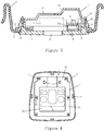
Figure 4 is a schematic top view of an operation panel of the vehicle roof console with various components assembled thereon; -
Figure 5 is a schematic top view of the operation panel of the vehicle roof console with an electric circuit board assembled thereon; -
Figure 6 is a schematic top view of the operation panel of the vehicle roof console; -
Figure 7 is a schematic top view of a cover plate of the vehicle roof console; -
Figure 8 is a view of the cover plate in the direction of arrow "A" inFigure 7 ; -
Figure 9 is a schematic bottom view of the cover plate; -
Figure 10 is an schematic top view of the electric circuit board of the vehicle roof console; and -
Figure 11 is a view of the electric circuit board in the direction of arrow "B" inFigure 10 . - Now some possible embodiments of the vehicle roof console of the disclosure will be described with reference to the drawings. It is noted that the drawings presented here are only illustrative, not forming any restriction to the scope of the disclosure. For the purpose of highlighting some features, various portions of the drawings are not drawn in scale, and some structures are sketched by dotted dash lines, while some other structures are omitted without shown here.
-
Figures 1-3 schematically show a vehicle roof console according to a possible embodiment of the disclosure, the vehicle roof console comprising anoperation panel 1 and amounting cover 2, wherein themounting cover 2 is mounted into a mounting socket formed in a roof trim 3 (seeFigure 3 ) from a location above the vehicle roof and is then fixed to the trim 3. After that, theoperation panel 1 is assembled to themounting cover 2 from a location below the vehicle roof InFigures 1 and 2 , the trim 3 is omitted for illustrating the positional relation between theoperation panel 1 and themounting cover 2. A casing of the roof console is constituted by theoperation panel 1 and themounting cover 2. - The
mounting cover 2 is formed into a single piece of a plastic material. As shown inFigure 3 , and with reference toFigure 2 , themounting cover 2 comprises abottom wall 21, severalclamping slot portions 22 formed on the outer peripheral portion of thebottom wall 21, andtop wall sections 23 defining a top wall of themounting cover 2. Thebottom wall 21 is in the form of a ring of a substantially flat plat, defining an opening therein. Corresponding to thebottom wall 21, the mounting socket of the trim 3 has asocket bottom plate 31, with an opening formed in thesocket bottom plate 31, the opening having a shape substantially consistent with the opening in thebottom wall 21. When themounting cover 2 is being assembled to the mounting socket of the trim 3, thebottom wall 21 is pushed against thesocket bottom plate 31, with their openings aligned with each other. Themounting cover 2 may be fixed to the trim 3, in particular fixed to thesocket bottom plate 31, by fasteners, adhesive or a fitting structure. - The
top wall sections 23 of themounting cover 2 are joined together and extend downwards to thebottom wall 21. In the top wall of themounting cover 2, there areapertures 24 between thetop wall sections 23 to establish an access path between the internal space of themounting cover 2 and the outside via theseapertures 24, so that components inside themounting cover 2 can be manipulated (for example, to conduct wiring or the like for them). Thetop wall sections 23 may have different heights with respect to thebottom wall 21 and different shapes, the heights and shapes of them being adapted in accordance with various components to be mounted inside themounting cover 2. - The
operation panel 1 has a substantially plate shaped main body, with severalflexible hooks 11 formed on the outer peripheral portion of the upper surface of the main body, theflexible hooks 11 being corresponding to theclamping slot portions 22 of themounting cover 2. When theflexible hooks 11 are inserted through correspondingclamping slot portions 22 and elastically clamped onto the edges of theclamping slot portions 22, theoperation panel 1 is removably fixed to themounting cover 2, and thus an internal space of the casing is defined between theoperation panel 1 and themounting cover 2. - It is appreciated that other fastening structure and/or fasteners that can removably fix the
operation panel 1 to themounting cover 2 in a simple manner, for example, by only an inserting action, can also be used here. - A capacitive gesture recognition module is carried on the upper side of the
operation panel 1. The capacitive gesture recognition module is frame shaped and mainly comprises anelectric circuit board 4 and acover plate 5, thecover plate 5 being configured to sealingly fix theelectric circuit board 4 to theoperation panel 1. Theelectric circuit board 4 and thecover plate 5 are located in the internal space of the casing.Connectors 41 and an electric circuit portion 42 (sketched by dotted dash lines inFigure 3 ) are disposed at a longitudinal end of theelectric circuit board 4. For this purpose, a corresponding portion of thecover plate 5 is formed with a raisedportion 55, with aninner cavity 55a defined inside the raisedportion 55. Theelectric circuit portion 42 is accommodated in theinner cavity 55a, and theconnectors 41 extend upwards through thecover plate 5 to be exposed from thecover plate 5. As shown inFigure 2 , via acorresponding aperture 24 in the top wall of themounting cover 2, an operator can manipulate theconnectors 41 from upside, for example, to conduct wiring. - Further, a roof illumination module 6 (sketched by dotted dash lines) is mounted to the
operation panel 1, theroof illumination module 6 being mounted substantially to a middle portion of theoperation panel 1. Theelectric circuit board 4 and thecover plate 5 each have a hollow central portion, so that that they can be arranged to surround theroof illumination module 6. Theroof illumination module 6 comprisesroof lights 61 andlight switches 62, all of them passing through corresponding holes 16 (seeFigures 5 and 6 , etc.) in theoperation panel 1 to be exposed to a lower side of the operation panel 1 (i.e., exposed to the vehicle cabin). - The
roof illumination module 6 may be mounted to theoperation panel 1 quickly in a snap-on manner. Of course, other mounting manners, for example, by using fasteners or other fitting structures, are also feasible. - Other modules, for example, a sunroof control module for controlling the operation of a sunroof of the vehicle, or the like, may also be mounted to the
operation panel 1. Said other modules are also surrounded by theelectric circuit board 4 and thecover plate 5, and are mounted to theoperation panel 1 in a way similar to theroof illumination module 6. Of course, said other modules may alternatively not be surrounded by theelectric circuit board 4 and thecover plate 5, but be disposed on the outside of theelectric circuit board 4 and thecover plate 5. Like theroof lights 61 andlight switches 62, manipulation knobs for other modules (the sunroof control module, etc.) pass through corresponding holes in theoperation panel 1 to be exposed to the lower side of theoperation panel 1. Since the manner of mounting other modules (the sunroof control module, etc.) with respect to the casing and the operation manner of them are similar to that of theroof illumination module 6, only theroof illumination module 6 will be described in details here. It is appreciated that the description to theroof illumination module 6 is equally applicable to other modules (the sunroof control module, etc.). - The
cover plate 5 may be fixed to theoperation panel 1 by means ofscrews 7 as illustrated, or by means of other fasteners or fastening structures. By arranging theelectric circuit board 4 and thecover plate 5 around the roof illumination module 6 (and may also around the sunroof control module or other modules), the capacitive gesture recognition module is independent with respect to the roof illumination module 6 (and also the sunroof control module or other modules) without interference with each other. The roof illumination module 6 (and also the sunroof control module or other modules) is not affected during the mounting and removing of the capacitive gesture recognition module. Further, theroof illumination module 6 and other possibly presented modules (the sunroof control module, etc.) are also independent of each other. The capacitive gesture recognition module, theroof illumination module 6 and other possibly presented modules (the sunroof control module, etc.) may be manufactured individually, and then assembled to the casing of the roof console of the disclosure without interference with each other. After that, they can be repaired, removed and replaced independently. Thus, the assembly and maintenance of the roof console of the disclosure is convenient. -
Figure 6 shows theoperation panel 1 from upper side, theoperation panel 1 being a single piece made of plastic and having a substantially trapezoidal profile. Theoperation panel 1 comprises a ring of anoutermost rim portion 12, and a ring of a raisedportion 13 protruded upwards near therim portion 12. In the assembled state shown inFigure 3 , the raisedportion 13 is inserted though the opening in thesocket bottom plate 31 of the trim 3 into the mountingcover 2, the portion of thesocket bottom plate 31 at the opening is clamped between thebottom wall 21 of the mountingcover 2 and therim portion 12 of theoperation panel 1, so that the whole casing is fixed to the trim 3. - The
operation panel 1 further comprises a ring of a strip ofsupport portion 14 at the inner side of the raisedportion 13, the strip ofsupport portion 14 having an inner profile that is substantially consistent with the outer profile of theelectric circuit board 4. A mountingarea 15 is formed at the inner side of the strip ofsupport portion 14, the mountingarea 15 comprising an circuit board mounting area (not marked in the figures) at the outer periphery and a middle portion surrounded by the circuit board mounting area, theelectric circuit board 4 being supported by the circuit board mounting area, and the middle portion being configured for forming theholes 16 therein and for supporting the roof illumination module 6 (and other possibly presented modules, such as the sunroof control module). The strip ofsupport portion 14 may be slightly higher than the mountingarea 15, and screwholes 17 are formed in the strip ofsupport portion 14, the screws 7 (if they are used) being screwed into the screw holes 17 and tightened herein. -
Figures 10 and 11 show theelectric circuit board 4 in different directions, theelectric circuit board 4 having a shape that permits it to be mounted to theoperation panel 1 around the roof illumination module 6 (and/or other possibly presented modules), such as a frame shape in any one of various closed forms (for example, rectangular, trapezoidal, polygonal, etc.) or non-closed forms (for example, U-shape, V-shape, etc.). In the illustrated exemplary embodiments, theelectric circuit board 4 has a main body having a shape of a substantially rectangular frame, the frame defining a hollow portion therein. The frame comprises a widerfirst frame portion 43 and three narrowersecond frame portions 44. On thefirst frame portion 43, theconnector 41 and theelectric circuit portion 42 associated with theconnector 41 are mounted. For example, as shown in this figure, twoconnectors 41 and oneelectric circuit portion 42 between the twoconnectors 41 are mounted. Opposite corners of thefirst frame portion 43 are recessed laterally inwards to accommodate the substantially trapezoidal outer periphery of theoperation panel 1. Further, several capacitive field sensors, four capacitive field sensors as shown in the figure, are disposed on the frame. Each capacitive field sensor comprises a pair of strip shapedcapacitive electrodes 46 disposed on upper and lower sides of the frame respectively. In each pair of thecapacitive electrodes 46, one is an emitter electrode, and the other is a receiver electrode, with a capacitive field being generated between the emitter electrode and the receiver electrode. The capacitive field covers a zone located upper behind the central console of the vehicle. When a hand of the driver presents a certain action or gesture, the capacitive field is changed, and theelectric circuit portion 42 senses the change in the capacitive field. The change in the capacitive field is used to judge the gesture of the driver's hand and thus determine the intention of the driver. Judging the gesture of the driver's hand and determining the intention of the driver can be achieved by theelectric circuit portion 42, or by a control unit that is connected to theelectric circuit portion 42. The control unit can control the corresponding vehicle appliance based on the driver's intention. - In the above embodiments, the
second frame portions 44 only need to have a width that is enough for carrying thecapacitive electrodes 46, and thus can be formed to be narrow, which facilitates the arrangement on theoperation panel 1. - According to an alternative embodiment, the
connector 41 and theelectric circuit portion 42 can be arranged on a separate electric circuit board which is also mounted to theoperation panel 1, and the separate electric circuit board is connected with theelectric circuit board 4 via wiring. In this embodiment, thefirst frame portion 43 may be formed to be as narrow as thesecond frame portions 44, that is to say, thefirst frame portion 43 only need to have a width that is enough for carrying thecapacitive electrodes 46. -
Figures 7-9 show thecover plate 5 in different directions, thecover plate 5 being also a single piece made of plastic and having a shape suitable for surrounding the roof illumination module 6 (and/or other possibly presented modules), such as a frame shape in any one of various closed forms (for example, rectangular, polygonal, etc.) or non-closed forms (for example, U-shape, V-shape, etc.). In the illustrated exemplary embodiments, thecover plate 5 comprises a substantially rectangular frame, the inner side of which defines ahollow portion 51. The frame comprises a widerfirst frame portion 52 and three narrowersecond frame portions 53. Thefirst frame portion 52 is formed withconnector holes 54 to be inserted through by theconnectors 41 of theelectric circuit board 4, and is formed with the raisedportion 55 that is located between the connector holes 54 and defines theinner cavity 55a. Opposite corners of thefirst frame portion 52 are recessed laterally inwards to form recessedportions 56 so as to accommodate the substantially trapezoidal outer periphery of theoperation panel 1.Undercuts 57 are formed at suitable locations of thecover plate 5, defining a decreased thickness here, and throughholes 58 to be inserted through by thescrews 7 are formed in portions corresponding to theundercuts 57. - As shown in
Figure 9 , the bottom side of thecover plate 5 is formed with arecess 59 for accommodating theelectric circuit board 4. Theinner cavity 55a and the connector holes 54 are all opened into therecess 59. The inner periphery of the recess is defined by an innerperipheral ridge 510. As shown inFigure 8 , the innerperipheral ridge 510 protrudes downwards slightly with respect to the bottom surface of the main body of thecover plate 5, to match with the height difference between the strip ofsupport portion 14 and the mountingarea 15 of theoperation panel 1. - The
electric circuit board 4 is arranged on the circuit board mounting area of the mountingarea 15 of theoperation panel 1 in an orientation in which theconnector 41 and theelectric circuit portion 42 face upwards, as shown inFigure 5 . - After that, as shown in
Figure 4 , thecover plate 5 is covered onto theelectric circuit board 4, and theelectric circuit board 4 is sealed between thecover plate 5 and theoperation panel 1. Theconnectors 41 are inserted through the connector holes 54 of thecover plate 5 to be exposed, and the gap between theconnector 41 and thecover plate 5 can be sealed by means of a suitable sealing structure, sealing elements or a sealing material. Then, thecover plate 5 is fixed to theoperation panel 1, for example, by using thescrews 7. Since theelectric circuit board 4 and thecover plate 5 both have a hollow middle portion, the middle portion of the mountingarea 15 is not occupied and faces upwards after theelectric circuit board 4 and thecover plate 5 are mounted to theoperation panel 1. Now theroof illumination module 6 and other possibly presented modules (the sunroof control module, etc.) can be mounted on theoperation panel 1. - Next, the
operation panel 1, which carries the capacitive gesture recognition module, theroof illumination module 6 and other possibly presented modules (the sunroof control module, etc.), is assembled to the mountingcover 2 via the opening in thesocket bottom plate 31 of the trim 3, as shown inFigure 3 , so that a complete roof console is formed. - It shall be noted that, in the embodiments that are shown in the figures and described above, the
electric circuit board 4 and thecover plate 5 are each in the form of a substantially rectangular frame, and thus the capacitive gesture recognition module is generally in the form of a substantially rectangular frame. The expression "substantially rectangular" used here means that neighboring sides of it may not form an absolute right angle therebetween, but there may be a small deviation, for example, less than 10 degrees, from absolute right angle. For example, thefirst frame portion 52 and a neighboringsecond frame portions 53 may form an angle therebetween in the range of 90 degrees ±10 degrees, preferably 90 degrees ±5 degrees. - It is appreciated that the capacitive gesture recognition module (as well as the
electric circuit board 4 and thecover plate 5 of it) of the disclosure may be formed as a frame of other shapes, for example, a frame having a trapezoidal shape, a polygonal shape and so on. In this condition, the total number, the shapes and the positions of the frame portions of theelectric circuit board 4 and thecover plate 5 may be determined according to concrete structure. A key point of the disclosure is that the frame shaped capacitive gesture recognition module can be disposed independently around the roof illumination module and other possibly presented modules, and the frame shaped capacitive gesture recognition module is particularly suitable for arranging strip shaped capacitive electrodes on it. - It shall be noted that the recognition ability (recognizable hand gestures, recognition precision, etc.) of the capacitive gesture recognition module depends to a large extent on the total number, the size and the distribution of the capacitive electrodes. Thus, for increasing the recognition ability of the capacitive gesture recognition module, as many capacitive electrodes as possible, with as large effective area as possible, can be arranged in the roof console, and the capacitive electrodes shall be located as near the outer periphery of the roof console as possible.
- Further, in order to arrange as large
capacitive electrodes 46 as possible in the space on the frame of theelectric circuit board 4, eachcapacitive electrode 46 shall extend along the corresponding frame portion to a distance as long as possible. For example, the length of eachcapacitive electrode 46 is 80% or more of the length of the corresponding frame portion. - It is appreciated that the structure of the roof console that is shown in the figures and described above is only exemplary, and those skilled in the art can design various roof consoles integrated with the capacitive gesture recognition module based on the basic concept of the disclosure and according to concrete vehicle structure.
- For example, in the illustrated embodiments, the mounting cover is mounted to the roof trim from upper side; it is appreciated that, however, by making modifications to the structure, the mounting cover may be mounted to the roof trim from the lower side. This solution also falls within the scope of the disclosure.
- According to the disclosure, the capacitive gesture recognition module and the roof illumination module and other possibly presented modules (the sunroof control module, etc.) are integrated into the roof console. These modules are mounted independent of each other, so various components in the roof console are easy to be mounted and removed, without interference with each other.
- Further, the casing of the roof console comprises a mounting cover and an operation panel mounted from upper and lower sides of the roof trim respectively, and the operation panel can be assembled to the mounting cover by a simple insert-in action, so the assembling and dissembling of the whole roof console is convenient.
- Further, the capacitive gesture recognition module is integrated in the existing roof console of the vehicle, and the spare mounting space around the roof illumination module and other possibly presented modules (the sunroof control module, etc.) is particularly efficiently used. The capacitive gesture recognition module incorporates the frame shaped electric circuit board and the frame shaped cover plate which are arranged around the roof illumination module and other possibly presented modules (the sunroof control module, etc.), so no additional mounting space is needed for the capacitive gesture recognition module, and the front windshield or roof trim structure does not need to be modified.
- Although the disclosure has been described above with reference to some preferred embodiments, the disclosure is not limited to these embodiments. It is thus appreciated that those skilled in the art can make various modifications to the disclosure without departing from the spirit of the disclosure, and all these modifications and their equivalents are also covered by the scope of the disclosure.
Claims (10)
- A vehicle roof console comprising:a mounting cover (2) fixed to a roof trim (3) of a vehicle;an operation panel (1) assembled to the mounting cover (2);a roof illumination module (6) mounted to a middle portion of the operation panel (1); anda capacitive gesture recognition module having a frame type configuration, mounted on the operation panel (1) around the roof illumination module (6) and being independently of the roof illumination module (6).
- The vehicle roof console of claim 1, further comprising a sunroof control module mounted to a middle portion of the operation panel (1) independently of the roof illumination module (6); and
optionally, the capacitive gesture recognition module is independently mounted to the operation panel (1) around the roof illumination module (6) and the sunroof control module. - The vehicle roof console of claim 1 or 2, wherein the capacitive gesture recognition module comprises: an electric circuit board (4) comprising pairs of strip shaped capacitive electrodes disposed on opposite sides in a thickness direction of the electric circuit board, each pair of capacitive electrodes comprising an emitter electrode and a receiver electrode; and a cover plate (5) configured to sealingly fix the electric circuit board (4) to the operation panel (1).
- The vehicle roof console of claim 3, wherein the electric circuit board (4) is provided with or connected with an electric circuit portion (42), the electric circuit portion (42) being configured to at least sense the change in a capacitive field due to the gesture of a hand of the vehicle driver, the capacitive field being generated by the capacitive electrodes, and the cover plate (5) is formed with a raised portion (55) for accommodating the electric circuit portion (42).
- The vehicle roof console of claim 3 or 4, wherein the electric circuit board (4) is further provided with or connected with a connector (41) associated with the electric circuit portion (42), the cover plate (5) is formed with a connector hole (54) to be inserted through by the connector (41), and the connector (41) is inserted through the connector hole (54) to reach a location above the cover plate (5); and
optionally, the cover plate (5) is formed with a recess (59) for receiving the electric circuit board (4) therein. - The vehicle roof console of any one of claims 3 to 5, wherein the electric circuit board (4) is in the form of a frame composed of frame portions, each frame portion being provided with corresponding capacitive electrodes on opposite sides in its thickness direction;
optionally, the frame portions comprise a first frame portion (43) which is not only provided with corresponding capacitive electrodes but also carries the electric circuit portion (42) and the connector (41); and second frame portions (44) which are provided only with corresponding capacitive electrodes; and
optionally, each of the second frame portions (44) has a width smaller than that of the first frame portion (43). - The vehicle roof console of claim 6, wherein the electric circuit board (4) comprises one first frame portion (43) and three second frame portions (44), the three second frame portions (44) and the one first frame portion (43) together form a substantially rectangular or trapezoidal frame.
- The vehicle roof console of claim 7, wherein each capacitive electrode has a length that is at least 80% of the length of the corresponding frame portion.
- The vehicle roof console of any one of claims 1 to 8, wherein the mounting cover (2) is fixed from above to the roof trim (3), and the operation panel (1) is assembled from below to the mounting cover (2); and
optionally, the operation panel (1) is removably assembled to the mounting cover (2) by means of a spring type clip structure. - The vehicle roof console of claim 9, wherein the mounting cover (2) is formed with an aperture (24) through which at least the capacitive gesture recognition module and the roof illumination module can be manipulated from above.
Applications Claiming Priority (1)
| Application Number | Priority Date | Filing Date | Title |
|---|---|---|---|
| CN201610997121.7A CN108068731B (en) | 2016-11-10 | 2016-11-10 | Vehicle roof console integrated with capacitive type gesture recognition module |
Publications (2)
| Publication Number | Publication Date |
|---|---|
| EP3321134A1 true EP3321134A1 (en) | 2018-05-16 |
| EP3321134B1 EP3321134B1 (en) | 2019-08-07 |
Family
ID=60269692
Family Applications (1)
| Application Number | Title | Priority Date | Filing Date |
|---|---|---|---|
| EP17200326.1A Active EP3321134B1 (en) | 2016-11-10 | 2017-11-07 | Vehicle roof console integrated with capacitive gesture recognition module |
Country Status (2)
| Country | Link |
|---|---|
| EP (1) | EP3321134B1 (en) |
| CN (1) | CN108068731B (en) |
Families Citing this family (1)
| Publication number | Priority date | Publication date | Assignee | Title |
|---|---|---|---|---|
| CN110040079B (en) * | 2018-06-06 | 2023-10-17 | 重庆市大明汽车电器有限公司 | Automobile touch control device |
Citations (7)
| Publication number | Priority date | Publication date | Assignee | Title |
|---|---|---|---|---|
| US20040227625A1 (en) * | 2003-05-15 | 2004-11-18 | Webasto Ag | Motor vehicle roof with a control means for electrical motor vehicle components and process for operating electrical motor vehicle components |
| EP1550579A1 (en) * | 2003-12-19 | 2005-07-06 | Valeo Vision | Lighting assembly inside the passenger compartment of vehicles |
| US20120049870A1 (en) * | 2010-08-25 | 2012-03-01 | Salter Stuart C | Proximity Sensor with Enhanced Activation |
| WO2014110317A2 (en) * | 2013-01-11 | 2014-07-17 | Johnson Controls Technology Company | A thin overhead console for a vehicle |
| WO2014138063A1 (en) * | 2013-03-04 | 2014-09-12 | Johnson Controls Technology Company | Vehicle interior component having an integral and configurable control assembly |
| US20160274664A1 (en) * | 2015-03-18 | 2016-09-22 | Ford Global Technologies, Llc | Proximity switch assembly having haptic feedback and method |
| KR20160116822A (en) * | 2015-03-31 | 2016-10-10 | 한국알프스 주식회사 | Proximity sensor type room lamp control device |
Family Cites Families (2)
| Publication number | Priority date | Publication date | Assignee | Title |
|---|---|---|---|---|
| KR101843825B1 (en) * | 2010-10-22 | 2018-05-14 | 후프 휼스벡 운트 휘르스트 게엠베하 운트 콤파니 카게 | Capacitive sensor arrangement for switching a door opening on a motor vehicle |
| JP6497540B2 (en) * | 2014-11-19 | 2019-04-10 | アイシン精機株式会社 | Operation detection device for opening and closing body for vehicle |
-
2016
- 2016-11-10 CN CN201610997121.7A patent/CN108068731B/en active Active
-
2017
- 2017-11-07 EP EP17200326.1A patent/EP3321134B1/en active Active
Patent Citations (7)
| Publication number | Priority date | Publication date | Assignee | Title |
|---|---|---|---|---|
| US20040227625A1 (en) * | 2003-05-15 | 2004-11-18 | Webasto Ag | Motor vehicle roof with a control means for electrical motor vehicle components and process for operating electrical motor vehicle components |
| EP1550579A1 (en) * | 2003-12-19 | 2005-07-06 | Valeo Vision | Lighting assembly inside the passenger compartment of vehicles |
| US20120049870A1 (en) * | 2010-08-25 | 2012-03-01 | Salter Stuart C | Proximity Sensor with Enhanced Activation |
| WO2014110317A2 (en) * | 2013-01-11 | 2014-07-17 | Johnson Controls Technology Company | A thin overhead console for a vehicle |
| WO2014138063A1 (en) * | 2013-03-04 | 2014-09-12 | Johnson Controls Technology Company | Vehicle interior component having an integral and configurable control assembly |
| US20160274664A1 (en) * | 2015-03-18 | 2016-09-22 | Ford Global Technologies, Llc | Proximity switch assembly having haptic feedback and method |
| KR20160116822A (en) * | 2015-03-31 | 2016-10-10 | 한국알프스 주식회사 | Proximity sensor type room lamp control device |
Also Published As
| Publication number | Publication date |
|---|---|
| EP3321134B1 (en) | 2019-08-07 |
| CN108068731B (en) | 2022-10-21 |
| CN108068731A (en) | 2018-05-25 |
Similar Documents
| Publication | Publication Date | Title |
|---|---|---|
| CN110182140A (en) | Sensor module | |
| CN108140288B (en) | Detector lens | |
| EP2060886A1 (en) | Combined sensor | |
| KR101760149B1 (en) | Internal frame for vapor extraction hood and vapor extraction hood | |
| US9992882B2 (en) | Electronic control unit | |
| EP3495211B1 (en) | Sensor mount structure | |
| US11059430B2 (en) | Sensor mount structure | |
| KR20090124995A (en) | Camera device | |
| JPH1029475A (en) | Instrument panel device | |
| CN112470457B (en) | Vehicle-mounted camera | |
| EP3321134B1 (en) | Vehicle roof console integrated with capacitive gesture recognition module | |
| US5971553A (en) | Mirror housing with electrical connector | |
| CN104228702A (en) | Peripheral structure of electrical component installing unit for installing electrical component to roof panel | |
| CN211335860U (en) | Novel car lamp switch panel | |
| JP7401172B2 (en) | Vehicle camera module | |
| CN209955874U (en) | Vehicle and be used for installing in side rear-view mirror of vehicle | |
| JP6767186B2 (en) | In-vehicle camera device | |
| EP3923262B1 (en) | Electronic apparatus | |
| JP2675279B2 (en) | Charge meter | |
| CN212766068U (en) | Waterproof structure of housing for housing electronic control unit for vehicle control | |
| EP3080979B1 (en) | Electronic apparatus with an improved bearing for a connecting unit, camera system for a motor vehicle and motor vehicle | |
| KR20190059600A (en) | Air conditioning system for automotive vehicles | |
| CN220190962U (en) | Vehicle-mounted camera device and vehicle | |
| KR101941749B1 (en) | Panel gauge and display device | |
| CN213119233U (en) | Display control module and electric appliance |
Legal Events
| Date | Code | Title | Description |
|---|---|---|---|
| PUAI | Public reference made under article 153(3) epc to a published international application that has entered the european phase |
Free format text: ORIGINAL CODE: 0009012 |
|
| STAA | Information on the status of an ep patent application or granted ep patent |
Free format text: STATUS: THE APPLICATION HAS BEEN PUBLISHED |
|
| AK | Designated contracting states |
Kind code of ref document: A1 Designated state(s): AL AT BE BG CH CY CZ DE DK EE ES FI FR GB GR HR HU IE IS IT LI LT LU LV MC MK MT NL NO PL PT RO RS SE SI SK SM TR |
|
| AX | Request for extension of the european patent |
Extension state: BA ME |
|
| STAA | Information on the status of an ep patent application or granted ep patent |
Free format text: STATUS: REQUEST FOR EXAMINATION WAS MADE |
|
| 17P | Request for examination filed |
Effective date: 20181116 |
|
| RBV | Designated contracting states (corrected) |
Designated state(s): AL AT BE BG CH CY CZ DE DK EE ES FI FR GB GR HR HU IE IS IT LI LT LU LV MC MK MT NL NO PL PT RO RS SE SI SK SM TR |
|
| GRAP | Despatch of communication of intention to grant a patent |
Free format text: ORIGINAL CODE: EPIDOSNIGR1 |
|
| RIC1 | Information provided on ipc code assigned before grant |
Ipc: B60Q 3/80 20170101ALI20190124BHEP Ipc: G06F 3/044 20060101ALI20190124BHEP Ipc: B60Q 3/208 20170101ALI20190124BHEP Ipc: B60R 13/02 20060101AFI20190124BHEP Ipc: G06F 3/01 20060101ALI20190124BHEP Ipc: H03K 17/96 20060101ALI20190124BHEP Ipc: B60Q 3/82 20170101ALI20190124BHEP Ipc: H03K 17/955 20060101ALI20190124BHEP |
|
| STAA | Information on the status of an ep patent application or granted ep patent |
Free format text: STATUS: GRANT OF PATENT IS INTENDED |
|
| INTG | Intention to grant announced |
Effective date: 20190228 |
|
| GRAS | Grant fee paid |
Free format text: ORIGINAL CODE: EPIDOSNIGR3 |
|
| GRAA | (expected) grant |
Free format text: ORIGINAL CODE: 0009210 |
|
| STAA | Information on the status of an ep patent application or granted ep patent |
Free format text: STATUS: THE PATENT HAS BEEN GRANTED |
|
| AK | Designated contracting states |
Kind code of ref document: B1 Designated state(s): AL AT BE BG CH CY CZ DE DK EE ES FI FR GB GR HR HU IE IS IT LI LT LU LV MC MK MT NL NO PL PT RO RS SE SI SK SM TR |
|
| REG | Reference to a national code |
Ref country code: GB Ref legal event code: FG4D |
|
| REG | Reference to a national code |
Ref country code: CH Ref legal event code: EP Ref country code: AT Ref legal event code: REF Ref document number: 1163341 Country of ref document: AT Kind code of ref document: T Effective date: 20190815 |
|
| REG | Reference to a national code |
Ref country code: DE Ref legal event code: R096 Ref document number: 602017005921 Country of ref document: DE |
|
| REG | Reference to a national code |
Ref country code: IE Ref legal event code: FG4D |
|
| REG | Reference to a national code |
Ref country code: NL Ref legal event code: MP Effective date: 20190807 |
|
| REG | Reference to a national code |
Ref country code: LT Ref legal event code: MG4D |
|
| PG25 | Lapsed in a contracting state [announced via postgrant information from national office to epo] |
Ref country code: FI Free format text: LAPSE BECAUSE OF FAILURE TO SUBMIT A TRANSLATION OF THE DESCRIPTION OR TO PAY THE FEE WITHIN THE PRESCRIBED TIME-LIMIT Effective date: 20190807 Ref country code: HR Free format text: LAPSE BECAUSE OF FAILURE TO SUBMIT A TRANSLATION OF THE DESCRIPTION OR TO PAY THE FEE WITHIN THE PRESCRIBED TIME-LIMIT Effective date: 20190807 Ref country code: SE Free format text: LAPSE BECAUSE OF FAILURE TO SUBMIT A TRANSLATION OF THE DESCRIPTION OR TO PAY THE FEE WITHIN THE PRESCRIBED TIME-LIMIT Effective date: 20190807 Ref country code: PT Free format text: LAPSE BECAUSE OF FAILURE TO SUBMIT A TRANSLATION OF THE DESCRIPTION OR TO PAY THE FEE WITHIN THE PRESCRIBED TIME-LIMIT Effective date: 20191209 Ref country code: NO Free format text: LAPSE BECAUSE OF FAILURE TO SUBMIT A TRANSLATION OF THE DESCRIPTION OR TO PAY THE FEE WITHIN THE PRESCRIBED TIME-LIMIT Effective date: 20191107 Ref country code: LT Free format text: LAPSE BECAUSE OF FAILURE TO SUBMIT A TRANSLATION OF THE DESCRIPTION OR TO PAY THE FEE WITHIN THE PRESCRIBED TIME-LIMIT Effective date: 20190807 Ref country code: NL Free format text: LAPSE BECAUSE OF FAILURE TO SUBMIT A TRANSLATION OF THE DESCRIPTION OR TO PAY THE FEE WITHIN THE PRESCRIBED TIME-LIMIT Effective date: 20190807 Ref country code: BG Free format text: LAPSE BECAUSE OF FAILURE TO SUBMIT A TRANSLATION OF THE DESCRIPTION OR TO PAY THE FEE WITHIN THE PRESCRIBED TIME-LIMIT Effective date: 20191107 |
|
| REG | Reference to a national code |
Ref country code: AT Ref legal event code: MK05 Ref document number: 1163341 Country of ref document: AT Kind code of ref document: T Effective date: 20190807 |
|
| PG25 | Lapsed in a contracting state [announced via postgrant information from national office to epo] |
Ref country code: GR Free format text: LAPSE BECAUSE OF FAILURE TO SUBMIT A TRANSLATION OF THE DESCRIPTION OR TO PAY THE FEE WITHIN THE PRESCRIBED TIME-LIMIT Effective date: 20191108 Ref country code: LV Free format text: LAPSE BECAUSE OF FAILURE TO SUBMIT A TRANSLATION OF THE DESCRIPTION OR TO PAY THE FEE WITHIN THE PRESCRIBED TIME-LIMIT Effective date: 20190807 Ref country code: AL Free format text: LAPSE BECAUSE OF FAILURE TO SUBMIT A TRANSLATION OF THE DESCRIPTION OR TO PAY THE FEE WITHIN THE PRESCRIBED TIME-LIMIT Effective date: 20190807 Ref country code: RS Free format text: LAPSE BECAUSE OF FAILURE TO SUBMIT A TRANSLATION OF THE DESCRIPTION OR TO PAY THE FEE WITHIN THE PRESCRIBED TIME-LIMIT Effective date: 20190807 Ref country code: IS Free format text: LAPSE BECAUSE OF FAILURE TO SUBMIT A TRANSLATION OF THE DESCRIPTION OR TO PAY THE FEE WITHIN THE PRESCRIBED TIME-LIMIT Effective date: 20191207 |
|
| PG25 | Lapsed in a contracting state [announced via postgrant information from national office to epo] |
Ref country code: TR Free format text: LAPSE BECAUSE OF FAILURE TO SUBMIT A TRANSLATION OF THE DESCRIPTION OR TO PAY THE FEE WITHIN THE PRESCRIBED TIME-LIMIT Effective date: 20190807 |
|
| RAP2 | Party data changed (patent owner data changed or rights of a patent transferred) |
Owner name: ROBERT BOSCH GMBH |
|
| PG25 | Lapsed in a contracting state [announced via postgrant information from national office to epo] |
Ref country code: EE Free format text: LAPSE BECAUSE OF FAILURE TO SUBMIT A TRANSLATION OF THE DESCRIPTION OR TO PAY THE FEE WITHIN THE PRESCRIBED TIME-LIMIT Effective date: 20190807 Ref country code: RO Free format text: LAPSE BECAUSE OF FAILURE TO SUBMIT A TRANSLATION OF THE DESCRIPTION OR TO PAY THE FEE WITHIN THE PRESCRIBED TIME-LIMIT Effective date: 20190807 Ref country code: PL Free format text: LAPSE BECAUSE OF FAILURE TO SUBMIT A TRANSLATION OF THE DESCRIPTION OR TO PAY THE FEE WITHIN THE PRESCRIBED TIME-LIMIT Effective date: 20190807 Ref country code: AT Free format text: LAPSE BECAUSE OF FAILURE TO SUBMIT A TRANSLATION OF THE DESCRIPTION OR TO PAY THE FEE WITHIN THE PRESCRIBED TIME-LIMIT Effective date: 20190807 Ref country code: DK Free format text: LAPSE BECAUSE OF FAILURE TO SUBMIT A TRANSLATION OF THE DESCRIPTION OR TO PAY THE FEE WITHIN THE PRESCRIBED TIME-LIMIT Effective date: 20190807 |
|
| PG25 | Lapsed in a contracting state [announced via postgrant information from national office to epo] |
Ref country code: SK Free format text: LAPSE BECAUSE OF FAILURE TO SUBMIT A TRANSLATION OF THE DESCRIPTION OR TO PAY THE FEE WITHIN THE PRESCRIBED TIME-LIMIT Effective date: 20190807 Ref country code: CZ Free format text: LAPSE BECAUSE OF FAILURE TO SUBMIT A TRANSLATION OF THE DESCRIPTION OR TO PAY THE FEE WITHIN THE PRESCRIBED TIME-LIMIT Effective date: 20190807 Ref country code: IS Free format text: LAPSE BECAUSE OF FAILURE TO SUBMIT A TRANSLATION OF THE DESCRIPTION OR TO PAY THE FEE WITHIN THE PRESCRIBED TIME-LIMIT Effective date: 20200224 Ref country code: SM Free format text: LAPSE BECAUSE OF FAILURE TO SUBMIT A TRANSLATION OF THE DESCRIPTION OR TO PAY THE FEE WITHIN THE PRESCRIBED TIME-LIMIT Effective date: 20190807 |
|
| REG | Reference to a national code |
Ref country code: DE Ref legal event code: R097 Ref document number: 602017005921 Country of ref document: DE |
|
| PLBE | No opposition filed within time limit |
Free format text: ORIGINAL CODE: 0009261 |
|
| STAA | Information on the status of an ep patent application or granted ep patent |
Free format text: STATUS: NO OPPOSITION FILED WITHIN TIME LIMIT |
|
| PG2D | Information on lapse in contracting state deleted |
Ref country code: IS |
|
| PG25 | Lapsed in a contracting state [announced via postgrant information from national office to epo] |
Ref country code: MC Free format text: LAPSE BECAUSE OF FAILURE TO SUBMIT A TRANSLATION OF THE DESCRIPTION OR TO PAY THE FEE WITHIN THE PRESCRIBED TIME-LIMIT Effective date: 20190807 Ref country code: LU Free format text: LAPSE BECAUSE OF NON-PAYMENT OF DUE FEES Effective date: 20191107 |
|
| 26N | No opposition filed |
Effective date: 20200603 |
|
| REG | Reference to a national code |
Ref country code: BE Ref legal event code: MM Effective date: 20191130 |
|
| PG25 | Lapsed in a contracting state [announced via postgrant information from national office to epo] |
Ref country code: SI Free format text: LAPSE BECAUSE OF FAILURE TO SUBMIT A TRANSLATION OF THE DESCRIPTION OR TO PAY THE FEE WITHIN THE PRESCRIBED TIME-LIMIT Effective date: 20190807 |
|
| PG25 | Lapsed in a contracting state [announced via postgrant information from national office to epo] |
Ref country code: ES Free format text: LAPSE BECAUSE OF FAILURE TO SUBMIT A TRANSLATION OF THE DESCRIPTION OR TO PAY THE FEE WITHIN THE PRESCRIBED TIME-LIMIT Effective date: 20190807 Ref country code: IE Free format text: LAPSE BECAUSE OF NON-PAYMENT OF DUE FEES Effective date: 20191107 |
|
| PG25 | Lapsed in a contracting state [announced via postgrant information from national office to epo] |
Ref country code: BE Free format text: LAPSE BECAUSE OF NON-PAYMENT OF DUE FEES Effective date: 20191130 |
|
| PG25 | Lapsed in a contracting state [announced via postgrant information from national office to epo] |
Ref country code: CY Free format text: LAPSE BECAUSE OF FAILURE TO SUBMIT A TRANSLATION OF THE DESCRIPTION OR TO PAY THE FEE WITHIN THE PRESCRIBED TIME-LIMIT Effective date: 20190807 |
|
| PG25 | Lapsed in a contracting state [announced via postgrant information from national office to epo] |
Ref country code: LI Free format text: LAPSE BECAUSE OF FAILURE TO SUBMIT A TRANSLATION OF THE DESCRIPTION OR TO PAY THE FEE WITHIN THE PRESCRIBED TIME-LIMIT Effective date: 20201130 Ref country code: CH Free format text: LAPSE BECAUSE OF FAILURE TO SUBMIT A TRANSLATION OF THE DESCRIPTION OR TO PAY THE FEE WITHIN THE PRESCRIBED TIME-LIMIT Effective date: 20201130 |
|
| REG | Reference to a national code |
Ref country code: CH Ref legal event code: PL |
|
| PG25 | Lapsed in a contracting state [announced via postgrant information from national office to epo] |
Ref country code: HU Free format text: LAPSE BECAUSE OF FAILURE TO SUBMIT A TRANSLATION OF THE DESCRIPTION OR TO PAY THE FEE WITHIN THE PRESCRIBED TIME-LIMIT; INVALID AB INITIO Effective date: 20171107 Ref country code: MT Free format text: LAPSE BECAUSE OF FAILURE TO SUBMIT A TRANSLATION OF THE DESCRIPTION OR TO PAY THE FEE WITHIN THE PRESCRIBED TIME-LIMIT Effective date: 20190807 |
|
| PG25 | Lapsed in a contracting state [announced via postgrant information from national office to epo] |
Ref country code: MK Free format text: LAPSE BECAUSE OF FAILURE TO SUBMIT A TRANSLATION OF THE DESCRIPTION OR TO PAY THE FEE WITHIN THE PRESCRIBED TIME-LIMIT Effective date: 20190807 |
|
| GBPC | Gb: european patent ceased through non-payment of renewal fee |
Effective date: 20211107 |
|
| PG25 | Lapsed in a contracting state [announced via postgrant information from national office to epo] |
Ref country code: GB Free format text: LAPSE BECAUSE OF NON-PAYMENT OF DUE FEES Effective date: 20211107 |
|
| PGFP | Annual fee paid to national office [announced via postgrant information from national office to epo] |
Ref country code: IT Payment date: 20231130 Year of fee payment: 7 Ref country code: FR Payment date: 20231124 Year of fee payment: 7 |
|
| PGFP | Annual fee paid to national office [announced via postgrant information from national office to epo] |
Ref country code: DE Payment date: 20240123 Year of fee payment: 7 |