EP3316929B1 - Medicament delivery device - Google Patents
Medicament delivery device Download PDFInfo
- Publication number
- EP3316929B1 EP3316929B1 EP16732299.9A EP16732299A EP3316929B1 EP 3316929 B1 EP3316929 B1 EP 3316929B1 EP 16732299 A EP16732299 A EP 16732299A EP 3316929 B1 EP3316929 B1 EP 3316929B1
- Authority
- EP
- European Patent Office
- Prior art keywords
- medicament delivery
- actuator
- delivery device
- plunger rod
- delivery member
- Prior art date
- Legal status (The legal status is an assumption and is not a legal conclusion. Google has not performed a legal analysis and makes no representation as to the accuracy of the status listed.)
- Active
Links
- 239000003814 drug Substances 0.000 title claims description 143
- 210000002105 tongue Anatomy 0.000 claims description 39
- 230000004913 activation Effects 0.000 claims description 23
- 230000007246 mechanism Effects 0.000 claims description 19
- 239000012190 activator Substances 0.000 claims description 15
- 239000000243 solution Substances 0.000 description 8
- 230000007704 transition Effects 0.000 description 4
- 230000008901 benefit Effects 0.000 description 3
- 230000006835 compression Effects 0.000 description 3
- 238000007906 compression Methods 0.000 description 3
- 230000002349 favourable effect Effects 0.000 description 3
- 230000003213 activating effect Effects 0.000 description 2
- 238000002347 injection Methods 0.000 description 2
- 239000007924 injection Substances 0.000 description 2
- 230000035515 penetration Effects 0.000 description 2
- 230000000284 resting effect Effects 0.000 description 2
- 208000012260 Accidental injury Diseases 0.000 description 1
- 238000010168 coupling process Methods 0.000 description 1
- 238000005859 coupling reaction Methods 0.000 description 1
- 230000001419 dependent effect Effects 0.000 description 1
- 230000003993 interaction Effects 0.000 description 1
- 238000004519 manufacturing process Methods 0.000 description 1
- 238000007391 self-medication Methods 0.000 description 1
Images


Classifications
-
- A—HUMAN NECESSITIES
- A61—MEDICAL OR VETERINARY SCIENCE; HYGIENE
- A61M—DEVICES FOR INTRODUCING MEDIA INTO, OR ONTO, THE BODY; DEVICES FOR TRANSDUCING BODY MEDIA OR FOR TAKING MEDIA FROM THE BODY; DEVICES FOR PRODUCING OR ENDING SLEEP OR STUPOR
- A61M5/00—Devices for bringing media into the body in a subcutaneous, intra-vascular or intramuscular way; Accessories therefor, e.g. filling or cleaning devices, arm-rests
- A61M5/178—Syringes
- A61M5/20—Automatic syringes, e.g. with automatically actuated piston rod, with automatic needle injection, filling automatically
- A61M5/2033—Spring-loaded one-shot injectors with or without automatic needle insertion
-
- A—HUMAN NECESSITIES
- A61—MEDICAL OR VETERINARY SCIENCE; HYGIENE
- A61M—DEVICES FOR INTRODUCING MEDIA INTO, OR ONTO, THE BODY; DEVICES FOR TRANSDUCING BODY MEDIA OR FOR TAKING MEDIA FROM THE BODY; DEVICES FOR PRODUCING OR ENDING SLEEP OR STUPOR
- A61M5/00—Devices for bringing media into the body in a subcutaneous, intra-vascular or intramuscular way; Accessories therefor, e.g. filling or cleaning devices, arm-rests
- A61M5/178—Syringes
- A61M5/31—Details
- A61M5/315—Pistons; Piston-rods; Guiding, blocking or restricting the movement of the rod or piston; Appliances on the rod for facilitating dosing ; Dosing mechanisms
- A61M5/31565—Administration mechanisms, i.e. constructional features, modes of administering a dose
- A61M5/31566—Means improving security or handling thereof
- A61M5/3157—Means providing feedback signals when administration is completed
-
- A—HUMAN NECESSITIES
- A61—MEDICAL OR VETERINARY SCIENCE; HYGIENE
- A61M—DEVICES FOR INTRODUCING MEDIA INTO, OR ONTO, THE BODY; DEVICES FOR TRANSDUCING BODY MEDIA OR FOR TAKING MEDIA FROM THE BODY; DEVICES FOR PRODUCING OR ENDING SLEEP OR STUPOR
- A61M5/00—Devices for bringing media into the body in a subcutaneous, intra-vascular or intramuscular way; Accessories therefor, e.g. filling or cleaning devices, arm-rests
- A61M5/178—Syringes
- A61M5/31—Details
- A61M5/315—Pistons; Piston-rods; Guiding, blocking or restricting the movement of the rod or piston; Appliances on the rod for facilitating dosing ; Dosing mechanisms
- A61M5/31565—Administration mechanisms, i.e. constructional features, modes of administering a dose
- A61M5/31576—Constructional features or modes of drive mechanisms for piston rods
-
- A—HUMAN NECESSITIES
- A61—MEDICAL OR VETERINARY SCIENCE; HYGIENE
- A61M—DEVICES FOR INTRODUCING MEDIA INTO, OR ONTO, THE BODY; DEVICES FOR TRANSDUCING BODY MEDIA OR FOR TAKING MEDIA FROM THE BODY; DEVICES FOR PRODUCING OR ENDING SLEEP OR STUPOR
- A61M5/00—Devices for bringing media into the body in a subcutaneous, intra-vascular or intramuscular way; Accessories therefor, e.g. filling or cleaning devices, arm-rests
- A61M5/178—Syringes
- A61M5/31—Details
- A61M5/32—Needles; Details of needles pertaining to their connection with syringe or hub; Accessories for bringing the needle into, or holding the needle on, the body; Devices for protection of needles
- A61M5/3205—Apparatus for removing or disposing of used needles or syringes, e.g. containers; Means for protection against accidental injuries from used needles
- A61M5/321—Means for protection against accidental injuries by used needles
- A61M5/3243—Means for protection against accidental injuries by used needles being axially-extensible, e.g. protective sleeves coaxially slidable on the syringe barrel
- A61M5/326—Fully automatic sleeve extension, i.e. in which triggering of the sleeve does not require a deliberate action by the user
-
- A—HUMAN NECESSITIES
- A61—MEDICAL OR VETERINARY SCIENCE; HYGIENE
- A61M—DEVICES FOR INTRODUCING MEDIA INTO, OR ONTO, THE BODY; DEVICES FOR TRANSDUCING BODY MEDIA OR FOR TAKING MEDIA FROM THE BODY; DEVICES FOR PRODUCING OR ENDING SLEEP OR STUPOR
- A61M5/00—Devices for bringing media into the body in a subcutaneous, intra-vascular or intramuscular way; Accessories therefor, e.g. filling or cleaning devices, arm-rests
- A61M5/178—Syringes
- A61M5/20—Automatic syringes, e.g. with automatically actuated piston rod, with automatic needle injection, filling automatically
- A61M2005/2006—Having specific accessories
- A61M2005/2013—Having specific accessories triggering of discharging means by contact of injector with patient body
-
- A—HUMAN NECESSITIES
- A61—MEDICAL OR VETERINARY SCIENCE; HYGIENE
- A61M—DEVICES FOR INTRODUCING MEDIA INTO, OR ONTO, THE BODY; DEVICES FOR TRANSDUCING BODY MEDIA OR FOR TAKING MEDIA FROM THE BODY; DEVICES FOR PRODUCING OR ENDING SLEEP OR STUPOR
- A61M5/00—Devices for bringing media into the body in a subcutaneous, intra-vascular or intramuscular way; Accessories therefor, e.g. filling or cleaning devices, arm-rests
- A61M5/178—Syringes
- A61M5/20—Automatic syringes, e.g. with automatically actuated piston rod, with automatic needle injection, filling automatically
- A61M2005/206—With automatic needle insertion
-
- A—HUMAN NECESSITIES
- A61—MEDICAL OR VETERINARY SCIENCE; HYGIENE
- A61M—DEVICES FOR INTRODUCING MEDIA INTO, OR ONTO, THE BODY; DEVICES FOR TRANSDUCING BODY MEDIA OR FOR TAKING MEDIA FROM THE BODY; DEVICES FOR PRODUCING OR ENDING SLEEP OR STUPOR
- A61M5/00—Devices for bringing media into the body in a subcutaneous, intra-vascular or intramuscular way; Accessories therefor, e.g. filling or cleaning devices, arm-rests
- A61M5/178—Syringes
- A61M5/20—Automatic syringes, e.g. with automatically actuated piston rod, with automatic needle injection, filling automatically
- A61M2005/2073—Automatic syringes, e.g. with automatically actuated piston rod, with automatic needle injection, filling automatically preventing premature release, e.g. by making use of a safety lock
- A61M2005/208—Release is possible only when device is pushed against the skin, e.g. using a trigger which is blocked or inactive when the device is not pushed against the skin
-
- A—HUMAN NECESSITIES
- A61—MEDICAL OR VETERINARY SCIENCE; HYGIENE
- A61M—DEVICES FOR INTRODUCING MEDIA INTO, OR ONTO, THE BODY; DEVICES FOR TRANSDUCING BODY MEDIA OR FOR TAKING MEDIA FROM THE BODY; DEVICES FOR PRODUCING OR ENDING SLEEP OR STUPOR
- A61M2205/00—General characteristics of the apparatus
- A61M2205/58—Means for facilitating use, e.g. by people with impaired vision
- A61M2205/581—Means for facilitating use, e.g. by people with impaired vision by audible feedback
Definitions
- the present invention relates to a medicament delivery device comprising a power unit with a specific activation mechanism.
- the device disclose therein has a number of automatic features like auto-penetration, auto-injection and automatic covering of the injection needle after removal of the medicament delivery device from the dose delivery site.
- the medicament delivery device according to WO 2011/005177 A1 comprises quite a lot of components that on the one hand provides an increased complexity regarding interaction between the components as well as increased assembly complexity and on the other hand increased manufacturing costs due to the number of components.
- CH 707 216 A2 discloses the closest prior art medicament delivery device, however lacking the audible indication of the needle sleeve being locked in an extended state.
- the aim of the present invention is to remedy the drawbacks of the state of the art medicament delivery devices and to provide a solution with a good functionality.
- a medicament delivery device comprising the features of the independent patent claim.
- Preferable embodiments of the invention form the subject of the dependent patent claims.
- the medicament delivery device may comprise a housing arranged to accommodate a medicament container.
- the housing may include a power unit arranged inside said housing.
- the power unit comprises a plunger rod, a drive spring, an actuator, and an actuator sleeve.
- the drive spring is operably arranged to act on the plunger rod, and which is, upon activation, operably arranged to act on the medicament container.
- the actuator may be arranged with holding elements, capable of releasibly holding the plunger rod with the drive spring in a tensioned state.
- the actuator cooperates with the actuator sleeve operably connected to the actuator for releasibly locking the holding elements in a holding state.
- the medicament delivery device may further comprise a medicament delivery member guard slidably movable in said housing and arranged to act on the actuator sleeve for setting the holding elements in a first activation state and an activator unit arranged to be manually operated, operably connected to said plunger rod for setting the holding elements in a second activation state, wherein the plunger rod is released when both activation states are set.
- a medicament delivery member guard slidably movable in said housing and arranged to act on the actuator sleeve for setting the holding elements in a first activation state
- an activator unit arranged to be manually operated, operably connected to said plunger rod for setting the holding elements in a second activation state, wherein the plunger rod is released when both activation states are set.
- both conditions have to be fulfilled in order to activate and release the plunger rod from the tensioned state.
- There is no sequence dependency i.e. there is no need to follow a sequence by first setting the first activation state followed by setting the second activation state.
- An advantage is that a user will not be confused how to activate the device.
- a further advantage with the solution is that the manually operated activation mechanism is operably connected to the plunger rod, thereby reducing the number of components that are used for activating the medicament delivery device.
- the holding elements may comprise a number of arms arranged with ledges arranged to engage recesses in plunger rod, thereby providing a positive mechanical locking function.
- the actuator sleeve may be arranged slidable in relation to the actuator, wherein movement of the medicament delivery member guard in a distal direction causes the actuator sleeve to move distally to the first activation state.
- the actuator sleeve connected to the medicament delivery member guard will cooperate with the actuator for setting the device in the first activation state.
- the activator unit may preferably be slidably movable, wherein movement of the activator unit in a proximal direction causes said plunger rod to move to the second activation state.
- the activator unit may preferably comprise push elements arranged to act on an end surface of the plunger rod. This enables a design of the activator unit as for example a push button or the like manually operated mechanism.
- the medicament delivery device may further comprise an end-of-dose signal mechanism. With such a mechanism, the user is alerted that the dose has been delivered and that it is safe to remove the medicament delivery device from the dose delivery site.
- the end-of-dose signal mechanism may according to one solution comprise the drive spring operably arranged between the plunger rod and the actuator. It may further comprise lock/release elements arranged to releasibly locking the actuator until the plunger rod has reached a proximal end position, wherein the lock/release elements releases the actuator, whereby the actuator is urged in the distal direction by the drive spring so that the actuator hits a fixed surface, producing said end-of-dose signal. This will thus produce an audible as well as a tactile signal to the user.
- the lock/release elements may comprise the holding elements and wherein said holding elements are arranged in the locking position by the plunger rod.
- the same components can have multiple functions.
- the medicament delivery device may further comprise a medicament delivery member guard spring arranged to force the medicament delivery member guard in a proximal direction after removal of the medicament delivery device and in that respect, the medicament delivery device may further comprises a medicament delivery member guard locking mechanism. This ensures that the medicament delivery member guard cannot be pushed distally after removal from the dose delivery site, preventing accidental injuries.
- the medicament delivery device may further comprise a medicament delivery member guard locking signal mechanism.
- the medicament delivery member guard locking signal mechanism may comprises the tongues of the holding elements interacting with a ledge on an inner surface of the actuator sleeve such that movement of the medicament delivery member guard in the proximal direction will cause the tongues to pass the ledge and flex in a generally radial direction, thereby causing a medicament delivery member guard locking signal.
- the user will then be presented with a second signal indicating that the medicament delivery member guard is safely locked and that the medicament delivery device now may be discarded.
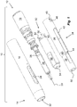
- Fig. 1 shows an example of an embodiment of a generally elongated medicament delivery device 10 comprising the present invention and having a distal end 12 and a proximal end 14.
- the medicament delivery device is provided with an elongated housing, comprising a proximal housing part 16 and a distal housing part 18.
- the distal end of the proximal housing part 16 is arranged with engagement means (not shown) such as annular recesses e.g. on its inner surface adapted to interface with corresponding engagement means 20, Fig. 3a , on e.g. the proximal outer surface of the distal housing part 18.
- the distal housing part 18 is further arranged with a central wall 22, Fig. 3b , which wall 22 is provided with a central passage 23.
- the proximal housing part 16 is arranged with elongated openings 24 for viewing a medicament container 26.
- the medicament container 26 is arranged with a movable stopper 28 and a medicament delivery member 30.
- the medicament delivery member 30 is integrated in the medicament container 26, but it is to be understood that the medicament delivery member 30 may be an attachable member wherein the attachment elements may be threads, bayonet fittings or luer-couplings, just to mention a few.
- the proximal housing part 16 is further arranged with a central passage 32 through which a medicament delivery member guard 34 can extend.
- the medicament delivery member guard 34 comprises a first proximal part 36 having a certain diameter and a second distal part 38 having a diameter larger than the proximal part, where these parts are joined by an intermediate conical part 40, Fig. 1 .
- Two elongated slits 42 are arranged along the medicament delivery member guard 34, on opposite sides thereof, for viewing the medicament container 26.
- On an inner surface of the conical part 40 a ledge 44 is arranged.
- each opening 46 is arranged with somewhat inwardly projecting, flexible, tongues 48, Fig. 1 .
- the medicament delivery member guard 34 is further arranged with a central opening 50 at its proximal end, through which the medicament delivery member 30 may protrude as will be described.
- a generally tubular medicament container holder 52 is slidably and coaxially arranged inside the medicament delivery member guard 34.
- the proximal part of the medicament container holder 52 is arranged with a neck portion 54 of lesser diameter. Adjacent the neck portion 54 cut-outs have been made on either side to form guide surfaces 56. These surfaces 56 cooperate with corresponding shapes of the inner surface of the medicament delivery member guard 34 in order to obtain a stop mechanism against rotation of the medicament container holder 52 relative the medicament delivery member guard 34.
- the distal end of the medicament container holder 52 is arranged with two distally extending tongues 58, where each tongue is arranged with an opening 60 and an inwardly directed ledge 62 on the distal edge of each opening, Fig. 1 .
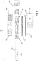
- the present invention relates to a power unit 64, Figs. 2-5 , that may be comprised in the medicament delivery device described above.
- the power pack comprises a holding element 66. It comprises a ring-shaped body 68, Fig. 4 , having an annular ledge 70 arranged around its circumference and a number of flexible tongues 72 directed towards the distal end of the device and wherein each tongue 72 is arranged with radial inwardly directed ledges 74.
- the holding element 66 is intended to interact with the container holder 52 as will be described below.
- the power unit 64 further comprises an actuator sleeve 76 which is slidably and coaxially arranged to the housing and connected to the medicament delivery member guard 34 as will be described below.
- the actuator sleeve 76 has a tubular shape and comprises a proximal end with a conical part 78 ending in a ledge 80 on its outer surface. At a distance from the ledge 80, a first annular ring 82 is arranged on the outer surface. A second annular ring 84 is also arranged a further distance from the ledge 80.
- the distal end of the actuator sleeve 76 is arranged with at least two oppositely arranged first cut-outs 86 of a generally rectangular shape.
- the distal end of the actuator sleeve 76 is further arranged with two oppositely arranged second cut-outs 88.
- An annular, proximally directed, ledge 89, Fig. 4 is arranged on the inner surface of the actuator sleeve 76.
- the actuator sleeve is further arranged with a distally directed, annular, ledge 91, Fig. 5 .
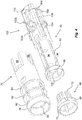
- a generally tubular actuator 90 is slidaby and coaxially arranged to the actuator sleeve 76.
- the actuator comprises a number of longitudinally directed cut-outs 92 that are arranged at the proximal end of the actuator 90 so as to form flexible tongues 94.
- the proximal end of each flexible tongue 94 has an inclined transition surface 96 which meets with a band-shaped part 98 with enlarged diameter.
- On the inner surface adjacent the transition surface 96 an annular inwardly directed ledge 100 is arranged.
- the tongues 94 with the ledges 100 form holding elements as will be described.
- the actuator 90 is also provided with two oppositely arranged stop elements 102 directed radially outwards from the outer surface on either side and having a proximally directed ledge 102a, where the widths of said proximally directed ledge 102a correspond to the width of the second cut-outs 88 of the actuator sleeve 76, Fig. 4 .
- the stop elements 102 further has a distally directed ledge 102b, the function of which will be described below.
- the stop elements 102 are arranged to fit into the second cut-outs 88.
- the actuator 90 is further provided with at least two oppositely ledges 104 directed radially outwards from the outer surface on either side arranged to mate the first cut-outs 86 of the of the actuator sleeve 76.
- the ledges 104 extend in the distal direction and are transformed into generally radially flexible arms 106, where the free ends of the arms are arrange with outwardly directed ledges 108. Further, the distal end of the actuator 90 is arranged with cut-outs 109, which form proximally directed support surfaces 110, the function of which will be described below.
- the power unit 64 further comprises a plunger rod 112 arranged to act on the stopper 28 of the medicament container 26.
- a drive spring that in the embodiment shown is a compression spring 114 is arranged inside the plunger rod 112 between a proximal wall 116 of the plunger rod 112, Fig. 3b , and a proximally directed support surface of generally radially directed ledges 118 arranged in a distal area of an elongated guide rod 120, which is extending through the drive spring 114.
- the ledges 118 of the guide rod 120 are arranged to fit inside the cut-outs 109 and engage with the support surfaces 110 of the actuator 90.
- the plunger rod 112 is arranged with a number of recesses that in the embodiment shown is a circumferential groove 122 with a certain width, wherein the annular inwardly directed ledge 100 of the actuator 90 and the radial inwardly directed ledges 74 of the holding element 66 fit into, Figs 4 and 5 . It is to be understood that the groove 122 may be replaced with a number of discrete recesses or cut-outs.
- a manually operated activator unit 124 e.g. a push button, has a distal portion protruding distally from the distal housing part 18.
- the activator unit 124 is arranged with two parts.
- An outer tubular first part 126, Fig. 6a is arranged slidable in a central passage 128, Fig. 2 , of the distal housing part 18.
- the first part 126 is arranged with a number of cut-outs 130 on opposite sides as well as longitudinally extending ridges 132 on the inner surface that terminate a distance before the end surface of the first part 126.
- the activator unit 124 further comprises a second part 134 having a generally disk-shaped body 136 having a diameter that corresponds to the inner diameter of first part 126 and arranged to fit such that a proximal surface of the disk-shaped body 136 is in contact with a distal end surface of the longitudinal ridges 132.
- the disk-shaped body 136 is further arranged with proximally directed tongues 138, which tongues have a first section 140 generally parallel with the longitudinal direction of the medicament delivery device.
- the first section 140 is interconnected with an outwardly inclined second section 142.
- the second section 142 is then interconnected with a third section 144 that is generally parallel with the longitudinal direction.
- the second section 142 is arranged with a distally directed ledge 146 that will engage a proximally directed end surface 148 of the cut-out 130 of the first part 126, Fig. 6b , when the two parts are interconnected. Further, the third section 144 will then be placed in the cut-out 130 when interconnected.
- the free end of the tongue 138 is further arranged with an inwardly directed ledge 150.
- the disk-shaped body 136 is arranged with two proximally directed arms 152.
- the device further comprises a medicament delivery member guard spring 154, coaxially arranged on the actuator sleeve 76.
- the annular proximal end of the medicament delivery member guard spring 154 is arranged resting on the second annular ring 84 of the actuator sleeve 76, Figs. 1 and 2
- the annular distal end of the medicament delivery member guard spring 154 is arranged resting on the proximal surface of the stop ledges 102 and 104 of the actuator 90, Fig. 2 .
- the invention is intended to function as follows.
- the guide rod 120 is pushed into the actuator 90 from the distal end until the ledges 118 of the guide rod 120 are snapped into the cut-outs 109 of the actuator 90.
- the actuator sleeve 76 with the medicament delivery member guard spring 154 is pushed onto the actuator 90 until the ledges 102, 104 of the actuator enter the cut-outs 86, 88 of the actuator sleeve 76, preventing further movement.
- the medicament delivery member guard spring 154 is tensioned and the tongues 94 of the actuator 90 may flex in the generally radial direction.
- the drive spring 114 is then entered into the plunger rod 112 and the drive spring 114 and plunger rod 112 are pushed into the actuator from the proximal direction, flexing the tongues 94 in the radial direction until the ledges 100 of the tongues 94 enter the annular groove 122, at the same time tensioning the drive spring 114.
- the holding element 66 is pushed onto the plunger rod 112 from the proximal direction until the ledges 74 of the holding element 66 also engage with the annular groove 122 of the plunger rod 112 and are positioned radially inwards of the tongues 94 of the actuator 90. Then the actuator sleeve 76 is pushed in the proximal direction onto the actuator 90, thereby preventing the ledges 100 of the tongues 94 of the actuator 90 as well as the ledges 74 of the holding element 66 from escaping the annular groove 122 of the plunger rod 112.
- This assembly is then pushed into the distal housing part 18 from the proximal direction and stop when the distally directed stop ledge 102b contacts the central wall 22 as seen in Fig. 3b .
- the two parts of the activator unit 124 are interconnected and pushed inside the distal housing part from the distal direction. When pushed inside, the ledge 150 of the second part of the activator unit 124 will engage the ledge 108 of the actuator 90 and interconnect the actuator 90 with the activator unit 124, thereby preventing movement of the actuator 90 in the proximal direction.
- the actuator sleeve 76 is pushed in the proximal direction, but is prevented from movement in the proximal direction due to the ledge 89 on the inner surface of the actuator sleeve 76 abutting the inclined transition surface 96 of the actuator 90 as seen in fig. 3a .
- a medicament container 26 is placed in the container holder 52 and the assembly is placed in the proximal housing part 16.
- the distal housing part 18 with the power unit 64 is then interconnected and locked to the proximal housing part by the attachment elements 20.
- the inwardly directed ledges 62 at the distal end of the medicament container holder 52 engage with the annular ledge 70 of the holding element 66, interconnecting them.
- the device is now ready to use.
- the distal part of the medicament delivery member guard 34 will surround the actuator sleeve 76 wherein the inclined tongues 48 will pass the ledge 80 providing a lock in the longitudinal direction of between the medicament delivery member guard 34 and the actuator sleeve 76.
- the proximal end of the medicament delivery device and thus the medicament delivery member guard 34 is pressed against a dose delivery site.
- the medicament delivery device apart from the stationary medicament delivery member guard and the inter-connected actuator sleeve 76, is moved in the proximal direction until the distal end of the actuator sleeve 76 comes in contact with the central wall 22 of the distal housing part 18, Fig. 7 , wherein the movement is stopped.
- the movement of the actuator 90 in relation to the actuator sleeve 76 has caused the band-shaped part 98 to protrude to some extent out of the proximal end of the actuator sleeve, Fig. 7 , setting the power unit in a first activation state.
- the proximally directed arms 152 will act on the distal end of the plunger rod 112 and push it in the proximal direction, setting the power unit in the second activation state. Because of the engagement of the actuator 90 with its ledges 100 in the annular groove 122 of the plunger rod 112, also the actuator 90 will move in the proximal direction, Fig. 8b .
- the first activation state is removed. If for instance the medicament delivery device would be removed from the dose delivery site, than the first activation state is removed. If now the activator unit 124 is pressed, the plunger rod 112 together with the actuator 90 will move proximally in relation to the actuator sleeve 76 to the second activation state, but because the actuator sleeve 76 has not been pushed distally by the medicament delivery member guard 34, the first activation state is not set and the plunger rod 112 will not be released.
- the plunger rod 112 is urged in the proximal direction. Since the ledges 74 of the holding element 66 is still in the annular groove 122 and the holding element 66 is connected to the medicament container holder 52, the medicament container holder 52 and the medicament container 26 with its medicament delivery member 30 will be moved in the proximal direction, when the plunger rod 112 is moved in the proximal direction, causing a penetration of the medicament delivery member 30 into the tissue of the patient. The movement of the medicament container holder 52 and the medicament container 26 is stopped when the proximally directed surfaces surrounding the neck portion 54 abut the ledge 44 on the inner surface of the medicament delivery member guard 34.
- the force of the compression spring 114 will urge the plunger rod in the proximal direction with such a force that the ledges of the holding element are forced out of the annular groove 122.
- the plunger rod 112 is acting on the stopper 28 and due to the incompressibility of the medicament inside the medicament container 26 as well as the small passage in the medicament delivery member 30, the medicament container 26 with its container holder 52 will be moved in the proximal direction causing a penetration of the medicament delivery member 30 into the tissue of the patient.
- the plunger rod 112 is urged further in the proximal direction wherein the ledges 74 of the holding element 66 will be forced out of engagement with the annular groove 122 due to the flexing properties of the tongues 72 of the holding element 66.
- the plunger rod 112 will now act on the stopper 28 inside the medicament container 26, whereby a dose of medicament will be expelled through the medicament delivery member 30.
- an end-of-dose signal mechanism will be activated in that the distal end of the plunger rod 112 has passed the ledges 100 of the actuator 90, Fig.
- the user may now remove the medicament delivery device from the dose delivery site. This will cause actuator sleeve 76 and the medicament delivery member guard 34 to be moved in the proximal direction due to the force from the medicament delivery member guard spring 154 acting on the actuator sleeve and because of the connection between the actuator sleeve 76 and the medicament delivery member guard 34, which movement will cause the medicament delivery member 30 to be shielded.
- the medicament delivery member guard 34 is locked because when the actuator sleeve 76 is moved in the proximal direction by the medicament delivery member guard spring 154, the band-shaped part 98 of the tongues 94 of the actuator 90 will pass the distally directed annular ledge 91 and flex in the radial direction, Fig.
- the tongues 94 will have the additional function of comprising a medicament delivery member guard locking mechanism. This will cause an audible as well as tactile signal that the medicament delivery member guard 34 is locked.
- the arms will also have the additional function of acting as a medicament delivery member guard locking signal mechanism. The lock will prevent any attempt to push it in the distal direction due to the band-shaped part 98 abutting the ledge 89. The device is now safe to discard.
Landscapes
- Health & Medical Sciences (AREA)
- Engineering & Computer Science (AREA)
- Heart & Thoracic Surgery (AREA)
- Vascular Medicine (AREA)
- Anesthesiology (AREA)
- Biomedical Technology (AREA)
- Hematology (AREA)
- Life Sciences & Earth Sciences (AREA)
- Animal Behavior & Ethology (AREA)
- General Health & Medical Sciences (AREA)
- Public Health (AREA)
- Veterinary Medicine (AREA)
- Environmental & Geological Engineering (AREA)
- Infusion, Injection, And Reservoir Apparatuses (AREA)
Description
- The present invention relates to a medicament delivery device comprising a power unit with a specific activation mechanism.
- A large number of medicament delivery devices for self-medication have been developed during the years, where many have a high degree of automatic functions and features in order to facilitate the use of the medicament delivery device, especially for unexperienced users.
- One device that has gained a lot of attention on the market for its functionality is disclosed in the document
WO 2011/005177 A1 . The device disclose therein has a number of automatic features like auto-penetration, auto-injection and automatic covering of the injection needle after removal of the medicament delivery device from the dose delivery site. - Even though working very well, the medicament delivery device according to
WO 2011/005177 A1 comprises quite a lot of components that on the one hand provides an increased complexity regarding interaction between the components as well as increased assembly complexity and on the other hand increased manufacturing costs due to the number of components. - In view of this, there is room for further development of the functionality of medicament delivery devices in line with the medicament delivery device disclosed in
WO 2011/005177 A1 .CH 707 216 A2 - The aim of the present invention is to remedy the drawbacks of the state of the art medicament delivery devices and to provide a solution with a good functionality.
- The aim is solved by a medicament delivery device comprising the features of the independent patent claim. Preferable embodiments of the invention form the subject of the dependent patent claims.
- The medicament delivery device may comprise a housing arranged to accommodate a medicament container. The housing may include a power unit arranged inside said housing. The power unit comprises a plunger rod, a drive spring, an actuator, and an actuator sleeve. The drive spring is operably arranged to act on the plunger rod, and which is, upon activation, operably arranged to act on the medicament container.
- Further, the actuator may be arranged with holding elements, capable of releasibly holding the plunger rod with the drive spring in a tensioned state. The actuator cooperates with the actuator sleeve operably connected to the actuator for releasibly locking the holding elements in a holding state.
- According to a favourable solution, the medicament delivery device may further comprise a medicament delivery member guard slidably movable in said housing and arranged to act on the actuator sleeve for setting the holding elements in a first activation state and an activator unit arranged to be manually operated, operably connected to said plunger rod for setting the holding elements in a second activation state, wherein the plunger rod is released when both activation states are set.
- Thus both conditions have to be fulfilled in order to activate and release the plunger rod from the tensioned state. There is no sequence dependency, i.e. there is no need to follow a sequence by first setting the first activation state followed by setting the second activation state. An advantage is that a user will not be confused how to activate the device. A further advantage with the solution is that the manually operated activation mechanism is operably connected to the plunger rod, thereby reducing the number of components that are used for activating the medicament delivery device.
- According to one favourable solution, the holding elements may comprise a number of arms arranged with ledges arranged to engage recesses in plunger rod, thereby providing a positive mechanical locking function.in this respect, the actuator sleeve may be arranged slidable in relation to the actuator, wherein movement of the medicament delivery member guard in a distal direction causes the actuator sleeve to move distally to the first activation state. Thus the actuator sleeve connected to the medicament delivery member guard will cooperate with the actuator for setting the device in the first activation state.
- The activator unit may preferably be slidably movable, wherein movement of the activator unit in a proximal direction causes said plunger rod to move to the second activation state. Thus, there are movements in opposite directions for activating the medicament delivery device by setting the medicament delivery device in the two activation states. The activator unit may preferably comprise push elements arranged to act on an end surface of the plunger rod. This enables a design of the activator unit as for example a push button or the like manually operated mechanism.
- According to a further preferable solution, the medicament delivery device may further comprise an end-of-dose signal mechanism. With such a mechanism, the user is alerted that the dose has been delivered and that it is safe to remove the medicament delivery device from the dose delivery site.
- The end-of-dose signal mechanism may according to one solution comprise the drive spring operably arranged between the plunger rod and the actuator. It may further comprise lock/release elements arranged to releasibly locking the actuator until the plunger rod has reached a proximal end position, wherein the lock/release elements releases the actuator, whereby the actuator is urged in the distal direction by the drive spring so that the actuator hits a fixed surface, producing said end-of-dose signal. This will thus produce an audible as well as a tactile signal to the user.
- According to a feasible solution, the lock/release elements may comprise the holding elements and wherein said holding elements are arranged in the locking position by the plunger rod. Thus the same components can have multiple functions.
- In order to increase the safety of the medicament delivery device, it may further comprise a medicament delivery member guard spring arranged to force the medicament delivery member guard in a proximal direction after removal of the medicament delivery device and in that respect, the medicament delivery device may further comprises a medicament delivery member guard locking mechanism. This ensures that the medicament delivery member guard cannot be pushed distally after removal from the dose delivery site, preventing accidental injuries.
- In this respect, the medicament delivery device may further comprise a medicament delivery member guard locking signal mechanism. According to one favourable solution, the medicament delivery member guard locking signal mechanism may comprises the tongues of the holding elements interacting with a ledge on an inner surface of the actuator sleeve such that movement of the medicament delivery member guard in the proximal direction will cause the tongues to pass the ledge and flex in a generally radial direction, thereby causing a medicament delivery member guard locking signal. Thus, the user will then be presented with a second signal indicating that the medicament delivery member guard is safely locked and that the medicament delivery device now may be discarded.
- These and other aspects of, and advantages with, the present invention will become apparent from the following detailed description of the invention and from the accompanying drawings.
- In the following detailed description of the invention, reference will be made to the accompanying drawings, of which
-
Fig. 1 shows an exploded view of an example of a medicament delivery device, -
Fig. 2 shows an exploded view of a power unit comprised in the medicament delivery device ofFig. 1 , -
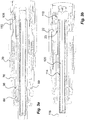
Fig. 3 is a c ross-sectional view of the power unit ofFig. 2 , -
Figs. 4-6 are detailed views of components comprised in the power unit ofFig. 2 , and -
Figs. 7-10 are cross-sectional view showing different functional states of the power unit ofFig. 2 . -
Fig. 1 shows an example of an embodiment of a generally elongatedmedicament delivery device 10 comprising the present invention and having adistal end 12 and aproximal end 14. The medicament delivery device is provided with an elongated housing, comprising aproximal housing part 16 and adistal housing part 18. The distal end of theproximal housing part 16 is arranged with engagement means (not shown) such as annular recesses e.g. on its inner surface adapted to interface with corresponding engagement means 20,Fig. 3a , on e.g. the proximal outer surface of thedistal housing part 18. Thedistal housing part 18 is further arranged with acentral wall 22,Fig. 3b , whichwall 22 is provided with acentral passage 23. - The
proximal housing part 16 is arranged withelongated openings 24 for viewing amedicament container 26. Themedicament container 26 is arranged with amovable stopper 28 and amedicament delivery member 30. In the embodiment shown, themedicament delivery member 30 is integrated in themedicament container 26, but it is to be understood that themedicament delivery member 30 may be an attachable member wherein the attachment elements may be threads, bayonet fittings or luer-couplings, just to mention a few. - The
proximal housing part 16 is further arranged with acentral passage 32 through which a medicamentdelivery member guard 34 can extend. The medicamentdelivery member guard 34 comprises a firstproximal part 36 having a certain diameter and a seconddistal part 38 having a diameter larger than the proximal part, where these parts are joined by an intermediateconical part 40,Fig. 1 . Twoelongated slits 42 are arranged along the medicamentdelivery member guard 34, on opposite sides thereof, for viewing themedicament container 26. On an inner surface of the conical part 40 aledge 44 is arranged. - Further, at the distal end of the medicament
delivery member guard 34 twoopenings 46 are arranged opposite each other, where eachopening 46 is arranged with somewhat inwardly projecting, flexible,tongues 48,Fig. 1 . The medicamentdelivery member guard 34 is further arranged with acentral opening 50 at its proximal end, through which themedicament delivery member 30 may protrude as will be described. - A generally tubular
medicament container holder 52 is slidably and coaxially arranged inside the medicamentdelivery member guard 34. The proximal part of themedicament container holder 52 is arranged with aneck portion 54 of lesser diameter. Adjacent theneck portion 54 cut-outs have been made on either side to form guide surfaces 56. Thesesurfaces 56 cooperate with corresponding shapes of the inner surface of the medicamentdelivery member guard 34 in order to obtain a stop mechanism against rotation of themedicament container holder 52 relative the medicamentdelivery member guard 34. The distal end of themedicament container holder 52 is arranged with two distally extendingtongues 58, where each tongue is arranged with anopening 60 and an inwardly directedledge 62 on the distal edge of each opening,Fig. 1 . - The present invention relates to a
power unit 64,Figs. 2-5 , that may be comprised in the medicament delivery device described above. The power pack comprises a holdingelement 66. It comprises a ring-shapedbody 68,Fig. 4 , having anannular ledge 70 arranged around its circumference and a number offlexible tongues 72 directed towards the distal end of the device and wherein eachtongue 72 is arranged with radial inwardly directedledges 74. The holdingelement 66 is intended to interact with thecontainer holder 52 as will be described below. Thepower unit 64 further comprises anactuator sleeve 76 which is slidably and coaxially arranged to the housing and connected to the medicamentdelivery member guard 34 as will be described below. - The
actuator sleeve 76 has a tubular shape and comprises a proximal end with aconical part 78 ending in aledge 80 on its outer surface. At a distance from theledge 80, a firstannular ring 82 is arranged on the outer surface. A secondannular ring 84 is also arranged a further distance from theledge 80. The distal end of theactuator sleeve 76 is arranged with at least two oppositely arranged first cut-outs 86 of a generally rectangular shape. The distal end of theactuator sleeve 76 is further arranged with two oppositely arranged second cut-outs 88. An annular, proximally directed,ledge 89,Fig. 4 , is arranged on the inner surface of theactuator sleeve 76. The actuator sleeve is further arranged with a distally directed, annular,ledge 91,Fig. 5 . - A generally
tubular actuator 90 is slidaby and coaxially arranged to theactuator sleeve 76. The actuator comprises a number of longitudinally directed cut-outs 92 that are arranged at the proximal end of theactuator 90 so as to formflexible tongues 94. The proximal end of eachflexible tongue 94 has aninclined transition surface 96 which meets with a band-shapedpart 98 with enlarged diameter. On the inner surface adjacent thetransition surface 96 an annular inwardly directedledge 100 is arranged. Thetongues 94 with theledges 100 form holding elements as will be described. - The
actuator 90 is also provided with two oppositely arrangedstop elements 102 directed radially outwards from the outer surface on either side and having a proximally directedledge 102a, where the widths of said proximally directedledge 102a correspond to the width of the second cut-outs 88 of theactuator sleeve 76,Fig. 4 . Thestop elements 102 further has a distally directedledge 102b, the function of which will be described below. Thestop elements 102 are arranged to fit into the second cut-outs 88. Theactuator 90 is further provided with at least twooppositely ledges 104 directed radially outwards from the outer surface on either side arranged to mate the first cut-outs 86 of the of theactuator sleeve 76. - Further, the
ledges 104 extend in the distal direction and are transformed into generally radiallyflexible arms 106, where the free ends of the arms are arrange with outwardly directedledges 108. Further, the distal end of theactuator 90 is arranged with cut-outs 109, which form proximally directed support surfaces 110, the function of which will be described below. - The
power unit 64 further comprises aplunger rod 112 arranged to act on thestopper 28 of themedicament container 26. A drive spring that in the embodiment shown is acompression spring 114 is arranged inside theplunger rod 112 between aproximal wall 116 of theplunger rod 112,Fig. 3b , and a proximally directed support surface of generally radially directedledges 118 arranged in a distal area of anelongated guide rod 120, which is extending through thedrive spring 114. Theledges 118 of theguide rod 120 are arranged to fit inside the cut-outs 109 and engage with the support surfaces 110 of theactuator 90. Theplunger rod 112 is arranged with a number of recesses that in the embodiment shown is acircumferential groove 122 with a certain width, wherein the annular inwardly directedledge 100 of theactuator 90 and the radial inwardly directedledges 74 of the holdingelement 66 fit into,Figs 4 and5 . It is to be understood that thegroove 122 may be replaced with a number of discrete recesses or cut-outs. - A manually operated
activator unit 124, e.g. a push button, has a distal portion protruding distally from thedistal housing part 18. Theactivator unit 124 is arranged with two parts. An outer tubularfirst part 126,Fig. 6a , is arranged slidable in acentral passage 128,Fig. 2 , of thedistal housing part 18. Thefirst part 126 is arranged with a number of cut-outs 130 on opposite sides as well as longitudinally extendingridges 132 on the inner surface that terminate a distance before the end surface of thefirst part 126. - The
activator unit 124 further comprises asecond part 134 having a generally disk-shapedbody 136 having a diameter that corresponds to the inner diameter offirst part 126 and arranged to fit such that a proximal surface of the disk-shapedbody 136 is in contact with a distal end surface of thelongitudinal ridges 132. The disk-shapedbody 136 is further arranged with proximally directedtongues 138, which tongues have afirst section 140 generally parallel with the longitudinal direction of the medicament delivery device. Thefirst section 140 is interconnected with an outwardly inclinedsecond section 142. Thesecond section 142 is then interconnected with athird section 144 that is generally parallel with the longitudinal direction. - The
second section 142 is arranged with a distally directedledge 146 that will engage a proximally directedend surface 148 of the cut-out 130 of thefirst part 126,Fig. 6b , when the two parts are interconnected. Further, thethird section 144 will then be placed in the cut-out 130 when interconnected. The free end of thetongue 138 is further arranged with an inwardly directedledge 150. The disk-shapedbody 136 is arranged with two proximally directedarms 152. - The device further comprises a medicament delivery
member guard spring 154, coaxially arranged on theactuator sleeve 76. The annular proximal end of the medicament deliverymember guard spring 154 is arranged resting on the secondannular ring 84 of theactuator sleeve 76,Figs. 1 and2 , and the annular distal end of the medicament deliverymember guard spring 154 is arranged resting on the proximal surface of thestop ledges actuator 90,Fig. 2 . - The invention is intended to function as follows. When the
power unit 64 is to be assembled, theguide rod 120 is pushed into the actuator 90 from the distal end until theledges 118 of theguide rod 120 are snapped into the cut-outs 109 of theactuator 90. Theactuator sleeve 76 with the medicament deliverymember guard spring 154 is pushed onto theactuator 90 until theledges outs actuator sleeve 76, preventing further movement. In this position the medicament deliverymember guard spring 154 is tensioned and thetongues 94 of theactuator 90 may flex in the generally radial direction. Thedrive spring 114 is then entered into theplunger rod 112 and thedrive spring 114 andplunger rod 112 are pushed into the actuator from the proximal direction, flexing thetongues 94 in the radial direction until theledges 100 of thetongues 94 enter theannular groove 122, at the same time tensioning thedrive spring 114. - The holding
element 66 is pushed onto theplunger rod 112 from the proximal direction until theledges 74 of the holdingelement 66 also engage with theannular groove 122 of theplunger rod 112 and are positioned radially inwards of thetongues 94 of theactuator 90. Then theactuator sleeve 76 is pushed in the proximal direction onto theactuator 90, thereby preventing theledges 100 of thetongues 94 of theactuator 90 as well as theledges 74 of the holdingelement 66 from escaping theannular groove 122 of theplunger rod 112. - This assembly is then pushed into the
distal housing part 18 from the proximal direction and stop when the distally directedstop ledge 102b contacts thecentral wall 22 as seen inFig. 3b . The two parts of theactivator unit 124 are interconnected and pushed inside the distal housing part from the distal direction. When pushed inside, theledge 150 of the second part of theactivator unit 124 will engage theledge 108 of theactuator 90 and interconnect theactuator 90 with theactivator unit 124, thereby preventing movement of theactuator 90 in the proximal direction. Further, theactuator sleeve 76 is pushed in the proximal direction, but is prevented from movement in the proximal direction due to theledge 89 on the inner surface of theactuator sleeve 76 abutting theinclined transition surface 96 of theactuator 90 as seen infig. 3a . - When the device is to be used, a
medicament container 26 is placed in thecontainer holder 52 and the assembly is placed in theproximal housing part 16. Thedistal housing part 18 with thepower unit 64 is then interconnected and locked to the proximal housing part by theattachment elements 20. Further, the inwardly directedledges 62 at the distal end of themedicament container holder 52 engage with theannular ledge 70 of the holdingelement 66, interconnecting them. The device is now ready to use. Also the distal part of the medicamentdelivery member guard 34 will surround theactuator sleeve 76 wherein theinclined tongues 48 will pass theledge 80 providing a lock in the longitudinal direction of between the medicamentdelivery member guard 34 and theactuator sleeve 76. - When the medicament delivery device is to be used, the proximal end of the medicament delivery device and thus the medicament
delivery member guard 34 is pressed against a dose delivery site. Now the medicament delivery device, apart from the stationary medicament delivery member guard and theinter-connected actuator sleeve 76, is moved in the proximal direction until the distal end of theactuator sleeve 76 comes in contact with thecentral wall 22 of thedistal housing part 18,Fig. 7 , wherein the movement is stopped. - The movement of the
actuator 90 in relation to theactuator sleeve 76 has caused the band-shapedpart 98 to protrude to some extent out of the proximal end of the actuator sleeve,Fig. 7 , setting the power unit in a first activation state. When the user now presses on theactivator unit 124 in the proximal direction the proximally directedarms 152 will act on the distal end of theplunger rod 112 and push it in the proximal direction, setting the power unit in the second activation state. Because of the engagement of theactuator 90 with itsledges 100 in theannular groove 122 of theplunger rod 112, also theactuator 90 will move in the proximal direction,Fig. 8b . This movement will cause the band-shapedpart 98 to be moved completely out of theactuator sleeve 76,Fig. 8a , and because of the resilient properties of thetongues 94 of theactuator 90, theledges 100 will move out of theannular groove 122 of theplunger rod 112, thereby releasing theplunger rod 112, which is due to that both activation states have been set. - If for instance the medicament delivery device would be removed from the dose delivery site, than the first activation state is removed. If now the
activator unit 124 is pressed, theplunger rod 112 together with theactuator 90 will move proximally in relation to theactuator sleeve 76 to the second activation state, but because theactuator sleeve 76 has not been pushed distally by the medicamentdelivery member guard 34, the first activation state is not set and theplunger rod 112 will not be released. - Due to the force of the
compression spring 114, theplunger rod 112 is urged in the proximal direction. Since theledges 74 of the holdingelement 66 is still in theannular groove 122 and the holdingelement 66 is connected to themedicament container holder 52, themedicament container holder 52 and themedicament container 26 with itsmedicament delivery member 30 will be moved in the proximal direction, when theplunger rod 112 is moved in the proximal direction, causing a penetration of themedicament delivery member 30 into the tissue of the patient. The movement of themedicament container holder 52 and themedicament container 26 is stopped when the proximally directed surfaces surrounding theneck portion 54 abut theledge 44 on the inner surface of the medicamentdelivery member guard 34. It may also be that the force of thecompression spring 114 will urge the plunger rod in the proximal direction with such a force that the ledges of the holding element are forced out of theannular groove 122. However, since theplunger rod 112 is acting on thestopper 28 and due to the incompressibility of the medicament inside themedicament container 26 as well as the small passage in themedicament delivery member 30, themedicament container 26 with itscontainer holder 52 will be moved in the proximal direction causing a penetration of themedicament delivery member 30 into the tissue of the patient. - The
plunger rod 112 is urged further in the proximal direction wherein theledges 74 of the holdingelement 66 will be forced out of engagement with theannular groove 122 due to the flexing properties of thetongues 72 of the holdingelement 66. Theplunger rod 112 will now act on thestopper 28 inside themedicament container 26, whereby a dose of medicament will be expelled through themedicament delivery member 30. When theplunger rod 112 has come to its most proximal position with thestopper 28 at the proximal end of themedicament container 26, an end-of-dose signal mechanism will be activated in that the distal end of theplunger rod 112 has passed theledges 100 of theactuator 90,Fig. 9 , whereby thetongues 94 of theactuator 90 can flex back radially inwards, which tongues 93 previously have had the additional function of acting as lock/release elements for theactuator 90. Due to the residual force of thedrive spring 114, with its distal end acting on theledges 118 of theguide rod 120, and since theledges 118 of theguide rod 120 are engaging theactuator 90, theactuator 90 will move suddenly in the distal direction. This will cause the distally directedledge 102b of theactuator 90 to hit thecentral wall 22 of thedistal housing part 18, producing an audible and tactile signal that the dose delivery sequence is completed. - The user may now remove the medicament delivery device from the dose delivery site. This will cause
actuator sleeve 76 and the medicamentdelivery member guard 34 to be moved in the proximal direction due to the force from the medicament deliverymember guard spring 154 acting on the actuator sleeve and because of the connection between theactuator sleeve 76 and the medicamentdelivery member guard 34, which movement will cause themedicament delivery member 30 to be shielded. In the extended position, the medicamentdelivery member guard 34 is locked because when theactuator sleeve 76 is moved in the proximal direction by the medicament deliverymember guard spring 154, the band-shapedpart 98 of thetongues 94 of theactuator 90 will pass the distally directedannular ledge 91 and flex in the radial direction,Fig. 10 , whereby thetongues 94 will have the additional function of comprising a medicament delivery member guard locking mechanism. This will cause an audible as well as tactile signal that the medicamentdelivery member guard 34 is locked. Thus, the arms will also have the additional function of acting as a medicament delivery member guard locking signal mechanism. The lock will prevent any attempt to push it in the distal direction due to the band-shapedpart 98 abutting theledge 89. The device is now safe to discard. - It is to be understood that the embodiment described above and shown in the drawings is to be regarded as a non-limiting example of the invention and that it may be modified in many ways within the scope of the patent claims.
-
- 10
- medicament delivery device
- 12
- distal end
- 14
- proximal end
- 16
- proximal housing part
- 18
- distal housing part
- 20
- engagement means
- 22
- central wall
- 23
- central passage
- 24
- opening
- 26
- medicament container
- 28
- stopper
- 30
- medicament delivery member
- 32
- central passage
- 34
- medicament delivery member guard
- 36
- proximal part
- 38
- distal part
- 40
- conical part
- 42
- slits
- 44
- ledge
- 46
- opening
- 48
- tongue
- 50
- central opening
- 52
- medicament container holder
- 54
- neck portion
- 56
- guide surface
- 58
- tongue
- 60
- opening
- 62
- ledge
- 64
- power unit
- 66
- holding element
- 68
- body
- 70
- annular ledge
- 72
- tongue
- 74
- ledge
- 76
- actuator sleeve
- 78
- conical part
- 80
- ledge
- 82
- first annular ring
- 84
- second annular ring
- 86
- first cut-out
- 88
- second cut-out
- 89
- ledge
- 90
- actuator
- 91
- ledge
- 92
- cut-out
- 94
- tongue
- 96
- transition surface
- 98
- band-shaped part
- 100
- ledge
- 102
- stop element
- 104
- ledge
- 106
- arm
- 108
- ledge
- 109
- cut-out
- 110
- support surface
- 112
- plunger rod
- 114
- drive spring
- 116
- proximal wall
- 118
- ledge
- 120
- guide rod
- 122
- groove
- 124
- activator unit
- 126
- first part
- 128
- central passage
- 130
- cut-out
- 132
- ridge
- 134
- second part
- 136
- body
- 138
- tongue
- 140
- first section
- 142
- second section
- 144
- third section
- 146
- ledge
- 148
- end surface
- 150
- ledge
- 152
- arm
- 154
- medicament delivery member guard spring
Claims (10)
- Medicament delivery device comprising:- a housing (16, 18), arranged to accommodate a medicament container (26);- a power unit (64) arranged inside said housing, said power unit comprising a plunger rod (112), a drive spring (114) operably arranged to act on the plunger rod (112) and, which is, upon activation, operably arranged to act on said medicament container (26), an actuator (90) comprising holding elements (94, 100), capable of releasibly holding said plunger rod (112) with said drive spring (114) in a tensioned state, and an actuator sleeve (76) operably connected to said actuator (90) for releasibly locking said holding elements (94, 100) in a holding state, wherein said holding elements (94, 100) comprise a number of tongues (94) arranged with ledges (100) arranged to engage recesses (122) in said plunger rod (112); said medicament delivery device further comprising:- a medicament delivery member guard (34) slidably movable in a distal direction in said housing (16, 18) and arranged to act on said actuator sleeve (76) for moving said actuator sleeve (76) distally in relation to the actuator (90) and for setting said holding elements (94, 100) with said actuator sleeve (76) in a first activation state; and- an activator unit (124) comprising push elements arranged to act on an end surface of said plunger rod, wherein said activation unit (124) is slidably movable and arranged to be manually operated in a proximal direction to move said plunger rod and thereby said holding elements (94, 100) proximally for setting said holding elements (94, 100) with said actuator sleeve (76) in a second activation state,wherein said plunger rod (112) is released when both activation states are set; and
wherein the drive spring (114) is operably arranged between the plunger rod (112) and the actuator (90),
the medicament delivery device further comprising a medicament delivery member guard spring (154) arranged to force said medicament delivery member guard (34) in a proximal direction after removal of said medicament delivery device,
the medicament delivery device further comprising a medicament delivery member guard locking mechanism, wherein said medicament delivery member guard locking mechanism comprises said tongues (100) of said holding elements (94, 100) interacting with a distally directed ledge (91) on an inner surface of said actuator sleeve (76) such that movement of said medicament delivery member guard (34) in the proximal direction will cause said tongues (94) to pass said ledge (91) and flex in a generally radial direction, whereby the engagement of the tongues (94) with the ledge (91) will lock any movement of medicament delivery member guard in the distal direction, and
the medicament delivery device further comprising a medicament delivery member guard locking signal mechanism, wherein said medicament delivery member guard locking mechanism comprises said tongues (100) of said holding elements (94, 100) interacting with a distally directed ledge (91) on an inner surface of said actuator sleeve (76) such that movement of said medicament delivery member guard (34) in the proximal direction will cause said tongues (94) to pass said ledge (91) and flex in a generally radial direction, generating a medicament delivery member guard locking signal. - Medicament delivery device according to claim 1, further comprising an end-of-dose signal mechanism, wherein said end-of-dose signal mechanism comprises said drive spring (114), lock/release elements (94, 100) arranged to releasibly locking said actuator (90) until said plunger rod (112) has reached a proximal end position, wherein said lock/release elements (94, 100) releases said actuator (90), whereby said actuator (90) is urged in the distal direction by said drive spring (114) so that said actuator (90) hits a fixed surface, producing said end-of-dose signal.
- Medicament delivery device according to claim 2, wherein said lock/release elements comprise said holding elements (94, 100) and wherein said holding elements (94, 100) are arranged in a locking position by said plunger rod (112).
- Medicament delivery device according to claim 1, wherein the push elements comprise a first part (126) and a second part (134).
- Medicament delivery device according to claim 4, wherein the first part (126) is slidably arranged in a central passage (128) of a distal part (128) of the housing, and wherein the first part comprises a number of cut-outs (130) on opposite sides and longitudinally extending ridges (132) on an inner surface of the first part (126), where the longitudinally extending ridges (132) extend a distance before the end surface of the first part (126).
- Medicament delivery device according to claim 4 or 5, wherein the second part (134) has a generally disk-shaped body (136) having a diameter that corresponds to the inner diameter of the first part (126) and arranged to fit such that a proximal surface of the disk-shaped body (136) is in contact with a distal end surface of the longitudinally extending ridges (132).
- Medicament delivery device according to claim 6, wherein the disk-shaped body (136) is arranged with proximally directed tongues (138), which tongues have a first section (140) generally parallel with the longitudinal direction of the medicament delivery device, wherein the first section (140) is interconnected with an outwardly inclined second section (142) and the second section (142) is then interconnected with a third section (144) that is generally parallel with the longitudinal direction.
- Medicament delivery device according to claim 7, wherein the second section (142) is arranged with a distally directed ledge (146) that engages a proximally directed end surface of the cut-out (130) of the first part (126), wherein the third section (144) is arranged in the cut-out (130), wherein the free end of the tongue (138) is arranged with an inwardly directed ledge (150), and wherein the disk-shaped body (136) is arranged with two proximally directed arms (152).
- Medicament delivery device according to claim 1, wherein the actuator (90) comprises two oppositely arranged stop elements (102) directed radially outwards from the outer surface on either side and having a proximally directed ledge (102a), and two oppositely directed ledges 104 directed radially outwards from the outer surface.
- Medicament delivery device according to claim 1 or 9, wherein the actuator sleeve comprises at least two oppositely arranged cut-outs (86) and two oppositely arranged second cut-outs (88).
Applications Claiming Priority (2)
| Application Number | Priority Date | Filing Date | Title |
|---|---|---|---|
| SE1550966 | 2015-07-03 | ||
| PCT/EP2016/064840 WO2017005518A1 (en) | 2015-07-03 | 2016-06-27 | Medicament delivery device |
Publications (2)
| Publication Number | Publication Date |
|---|---|
| EP3316929A1 EP3316929A1 (en) | 2018-05-09 |
| EP3316929B1 true EP3316929B1 (en) | 2021-05-05 |
Family
ID=56235834
Family Applications (1)
| Application Number | Title | Priority Date | Filing Date |
|---|---|---|---|
| EP16732299.9A Active EP3316929B1 (en) | 2015-07-03 | 2016-06-27 | Medicament delivery device |
Country Status (7)
| Country | Link |
|---|---|
| US (2) | US11077250B2 (en) |
| EP (1) | EP3316929B1 (en) |
| JP (2) | JP6662916B2 (en) |
| KR (1) | KR102105750B1 (en) |
| DK (1) | DK3316929T3 (en) |
| TW (1) | TWI615164B (en) |
| WO (1) | WO2017005518A1 (en) |
Families Citing this family (5)
| Publication number | Priority date | Publication date | Assignee | Title |
|---|---|---|---|---|
| JP7194756B2 (en) | 2018-06-08 | 2022-12-22 | アンタレス・ファーマ・インコーポレーテッド | auto-insertion syringe |
| EP4121143A1 (en) * | 2020-03-17 | 2023-01-25 | SHL Medical AG | Medicament delivery device with a locking mechanism |
| WO2023066677A1 (en) * | 2021-10-19 | 2023-04-27 | Shl Medical Ag | Automatic feedback mechanism for a medicament delivery device |
| WO2023180068A1 (en) * | 2022-03-22 | 2023-09-28 | Shl Medical Ag | Sub-assemblies for medicament delivery devices and corresponding methods of assembly |
| EP4249017A1 (en) * | 2022-03-25 | 2023-09-27 | Becton Dickinson France | Automatic injection device |
Family Cites Families (13)
| Publication number | Priority date | Publication date | Assignee | Title |
|---|---|---|---|---|
| DE10229138B4 (en) | 2002-06-28 | 2008-01-31 | Tecpharma Licensing Ag | Product diverter with piston rod emergency reset |
| US20050101919A1 (en) * | 2003-11-07 | 2005-05-12 | Lennart Brunnberg | Device for an injector |
| CN102099069B (en) | 2008-05-20 | 2013-11-27 | Shl集团有限责任公司 | Device for medicament delivery device |
| TWI393578B (en) | 2009-07-07 | 2013-04-21 | Shl Group Ab | Injection device |
| US20140058333A1 (en) * | 2011-04-21 | 2014-02-27 | Sanofi-Aventis Deutschland Gmbh | Medicated module with automatic reservoir engagement and lock mechanism |
| WO2014005808A1 (en) | 2012-07-06 | 2014-01-09 | Carebay Europe Ltd | Medicament delivery device |
| KR101716593B1 (en) | 2012-10-05 | 2017-03-27 | 케어베이 유럽 리미티드 | Medicament delivery device |
| TWI653069B (en) | 2013-03-11 | 2019-03-11 | 德商賽諾菲阿凡提斯德意志有限公司 | "piston rod and drug delivery device comprising the piston rod" |
| WO2014166890A1 (en) | 2013-04-10 | 2014-10-16 | Sanofi | Injection device |
| JP2016518903A (en) | 2013-04-10 | 2016-06-30 | サノフイ | Injection device |
| JP6092040B2 (en) | 2013-08-02 | 2017-03-08 | 東京エレクトロン株式会社 | Silicon film forming method and apparatus therefor |
| CN105592874B (en) * | 2013-08-29 | 2019-06-04 | 卡贝欧洲有限公司 | Medicament delivery device |
| CH707216A2 (en) | 2014-03-06 | 2014-04-30 | Tecpharma Licensing Ag | Injection device i.e. auto injector, for injecting e.g. insulin to patient, has piston rod and drive spring distally displaced, and holding device distally driven by rod and spring by distal movement of release button |
-
2016
- 2016-06-27 KR KR1020177037841A patent/KR102105750B1/en active IP Right Grant
- 2016-06-27 EP EP16732299.9A patent/EP3316929B1/en active Active
- 2016-06-27 WO PCT/EP2016/064840 patent/WO2017005518A1/en active Application Filing
- 2016-06-27 JP JP2017567423A patent/JP6662916B2/en active Active
- 2016-06-27 DK DK16732299.9T patent/DK3316929T3/en active
- 2016-06-27 US US15/739,967 patent/US11077250B2/en active Active
- 2016-06-29 TW TW105120602A patent/TWI615164B/en active
-
2019
- 2019-12-05 JP JP2019220494A patent/JP6944508B2/en active Active
-
2021
- 2021-06-29 US US17/361,546 patent/US11596742B2/en active Active
Also Published As
| Publication number | Publication date |
|---|---|
| JP2020049241A (en) | 2020-04-02 |
| KR20180015188A (en) | 2018-02-12 |
| EP3316929A1 (en) | 2018-05-09 |
| DK3316929T3 (en) | 2021-07-26 |
| JP6662916B2 (en) | 2020-03-11 |
| JP2018519086A (en) | 2018-07-19 |
| WO2017005518A1 (en) | 2017-01-12 |
| US20180185583A1 (en) | 2018-07-05 |
| US11077250B2 (en) | 2021-08-03 |
| TWI615164B (en) | 2018-02-21 |
| US20210386934A1 (en) | 2021-12-16 |
| US11596742B2 (en) | 2023-03-07 |
| TW201711711A (en) | 2017-04-01 |
| KR102105750B1 (en) | 2020-04-29 |
| JP6944508B2 (en) | 2021-10-06 |
Similar Documents
| Publication | Publication Date | Title |
|---|---|---|
| US11596742B2 (en) | Medicament delivery device | |
| EP2485786B1 (en) | Medicament delivery device | |
| AU2013326601B2 (en) | Medicament delivery device | |
| US20170252518A1 (en) | Medicament Delivery Device Comprising a Locking Mechanism Having a Lever | |
| US20050101919A1 (en) | Device for an injector | |
| EP3204072B1 (en) | A power pack assembly for a medicament delivery device | |
| WO2011005177A1 (en) | Injection device | |
| EP3452146B1 (en) | Drive assembly for a medicament delivery device | |
| EP3380156B1 (en) | Medicament delivery device | |
| US20230082704A1 (en) | Medicament delivery device with a locking mechanism | |
| WO2021185478A1 (en) | Medicament delivery device with a locking mechanism |
Legal Events
| Date | Code | Title | Description |
|---|---|---|---|
| STAA | Information on the status of an ep patent application or granted ep patent |
Free format text: STATUS: THE INTERNATIONAL PUBLICATION HAS BEEN MADE |
|
| PUAI | Public reference made under article 153(3) epc to a published international application that has entered the european phase |
Free format text: ORIGINAL CODE: 0009012 |
|
| STAA | Information on the status of an ep patent application or granted ep patent |
Free format text: STATUS: REQUEST FOR EXAMINATION WAS MADE |
|
| 17P | Request for examination filed |
Effective date: 20171128 |
|
| AK | Designated contracting states |
Kind code of ref document: A1 Designated state(s): AL AT BE BG CH CY CZ DE DK EE ES FI FR GB GR HR HU IE IS IT LI LT LU LV MC MK MT NL NO PL PT RO RS SE SI SK SM TR |
|
| AX | Request for extension of the european patent |
Extension state: BA ME |
|
| DAV | Request for validation of the european patent (deleted) | ||
| DAX | Request for extension of the european patent (deleted) | ||
| RAP1 | Party data changed (applicant data changed or rights of an application transferred) |
Owner name: SHL MEDICAL AG |
|
| STAA | Information on the status of an ep patent application or granted ep patent |
Free format text: STATUS: EXAMINATION IS IN PROGRESS |
|
| 17Q | First examination report despatched |
Effective date: 20190327 |
|
| STAA | Information on the status of an ep patent application or granted ep patent |
Free format text: STATUS: EXAMINATION IS IN PROGRESS |
|
| GRAP | Despatch of communication of intention to grant a patent |
Free format text: ORIGINAL CODE: EPIDOSNIGR1 |
|
| STAA | Information on the status of an ep patent application or granted ep patent |
Free format text: STATUS: GRANT OF PATENT IS INTENDED |
|
| INTG | Intention to grant announced |
Effective date: 20210205 |
|
| GRAS | Grant fee paid |
Free format text: ORIGINAL CODE: EPIDOSNIGR3 |
|
| GRAA | (expected) grant |
Free format text: ORIGINAL CODE: 0009210 |
|
| STAA | Information on the status of an ep patent application or granted ep patent |
Free format text: STATUS: THE PATENT HAS BEEN GRANTED |
|
| AK | Designated contracting states |
Kind code of ref document: B1 Designated state(s): AL AT BE BG CH CY CZ DE DK EE ES FI FR GB GR HR HU IE IS IT LI LT LU LV MC MK MT NL NO PL PT RO RS SE SI SK SM TR |
|
| REG | Reference to a national code |
Ref country code: GB Ref legal event code: FG4D |
|
| REG | Reference to a national code |
Ref country code: CH Ref legal event code: EP |
|
| REG | Reference to a national code |
Ref country code: AT Ref legal event code: REF Ref document number: 1389004 Country of ref document: AT Kind code of ref document: T Effective date: 20210515 |
|
| REG | Reference to a national code |
Ref country code: IE Ref legal event code: FG4D |
|
| REG | Reference to a national code |
Ref country code: DE Ref legal event code: R096 Ref document number: 602016057355 Country of ref document: DE |
|
| REG | Reference to a national code |
Ref country code: DK Ref legal event code: T3 Effective date: 20210721 |
|
| REG | Reference to a national code |
Ref country code: LT Ref legal event code: MG9D |
|
| REG | Reference to a national code |
Ref country code: AT Ref legal event code: MK05 Ref document number: 1389004 Country of ref document: AT Kind code of ref document: T Effective date: 20210505 |
|
| PG25 | Lapsed in a contracting state [announced via postgrant information from national office to epo] |
Ref country code: HR Free format text: LAPSE BECAUSE OF FAILURE TO SUBMIT A TRANSLATION OF THE DESCRIPTION OR TO PAY THE FEE WITHIN THE PRESCRIBED TIME-LIMIT Effective date: 20210505 Ref country code: AT Free format text: LAPSE BECAUSE OF FAILURE TO SUBMIT A TRANSLATION OF THE DESCRIPTION OR TO PAY THE FEE WITHIN THE PRESCRIBED TIME-LIMIT Effective date: 20210505 Ref country code: BG Free format text: LAPSE BECAUSE OF FAILURE TO SUBMIT A TRANSLATION OF THE DESCRIPTION OR TO PAY THE FEE WITHIN THE PRESCRIBED TIME-LIMIT Effective date: 20210805 Ref country code: LT Free format text: LAPSE BECAUSE OF FAILURE TO SUBMIT A TRANSLATION OF THE DESCRIPTION OR TO PAY THE FEE WITHIN THE PRESCRIBED TIME-LIMIT Effective date: 20210505 Ref country code: FI Free format text: LAPSE BECAUSE OF FAILURE TO SUBMIT A TRANSLATION OF THE DESCRIPTION OR TO PAY THE FEE WITHIN THE PRESCRIBED TIME-LIMIT Effective date: 20210505 |
|
| PG25 | Lapsed in a contracting state [announced via postgrant information from national office to epo] |
Ref country code: GR Free format text: LAPSE BECAUSE OF FAILURE TO SUBMIT A TRANSLATION OF THE DESCRIPTION OR TO PAY THE FEE WITHIN THE PRESCRIBED TIME-LIMIT Effective date: 20210806 Ref country code: IS Free format text: LAPSE BECAUSE OF FAILURE TO SUBMIT A TRANSLATION OF THE DESCRIPTION OR TO PAY THE FEE WITHIN THE PRESCRIBED TIME-LIMIT Effective date: 20210905 Ref country code: LV Free format text: LAPSE BECAUSE OF FAILURE TO SUBMIT A TRANSLATION OF THE DESCRIPTION OR TO PAY THE FEE WITHIN THE PRESCRIBED TIME-LIMIT Effective date: 20210505 Ref country code: NO Free format text: LAPSE BECAUSE OF FAILURE TO SUBMIT A TRANSLATION OF THE DESCRIPTION OR TO PAY THE FEE WITHIN THE PRESCRIBED TIME-LIMIT Effective date: 20210805 Ref country code: PT Free format text: LAPSE BECAUSE OF FAILURE TO SUBMIT A TRANSLATION OF THE DESCRIPTION OR TO PAY THE FEE WITHIN THE PRESCRIBED TIME-LIMIT Effective date: 20210906 Ref country code: PL Free format text: LAPSE BECAUSE OF FAILURE TO SUBMIT A TRANSLATION OF THE DESCRIPTION OR TO PAY THE FEE WITHIN THE PRESCRIBED TIME-LIMIT Effective date: 20210505 Ref country code: RS Free format text: LAPSE BECAUSE OF FAILURE TO SUBMIT A TRANSLATION OF THE DESCRIPTION OR TO PAY THE FEE WITHIN THE PRESCRIBED TIME-LIMIT Effective date: 20210505 Ref country code: SE Free format text: LAPSE BECAUSE OF FAILURE TO SUBMIT A TRANSLATION OF THE DESCRIPTION OR TO PAY THE FEE WITHIN THE PRESCRIBED TIME-LIMIT Effective date: 20210505 |
|
| REG | Reference to a national code |
Ref country code: NL Ref legal event code: MP Effective date: 20210505 |
|
| PG25 | Lapsed in a contracting state [announced via postgrant information from national office to epo] |
Ref country code: NL Free format text: LAPSE BECAUSE OF FAILURE TO SUBMIT A TRANSLATION OF THE DESCRIPTION OR TO PAY THE FEE WITHIN THE PRESCRIBED TIME-LIMIT Effective date: 20210505 |
|
| PG25 | Lapsed in a contracting state [announced via postgrant information from national office to epo] |
Ref country code: RO Free format text: LAPSE BECAUSE OF FAILURE TO SUBMIT A TRANSLATION OF THE DESCRIPTION OR TO PAY THE FEE WITHIN THE PRESCRIBED TIME-LIMIT Effective date: 20210505 Ref country code: ES Free format text: LAPSE BECAUSE OF FAILURE TO SUBMIT A TRANSLATION OF THE DESCRIPTION OR TO PAY THE FEE WITHIN THE PRESCRIBED TIME-LIMIT Effective date: 20210505 Ref country code: CZ Free format text: LAPSE BECAUSE OF FAILURE TO SUBMIT A TRANSLATION OF THE DESCRIPTION OR TO PAY THE FEE WITHIN THE PRESCRIBED TIME-LIMIT Effective date: 20210505 Ref country code: EE Free format text: LAPSE BECAUSE OF FAILURE TO SUBMIT A TRANSLATION OF THE DESCRIPTION OR TO PAY THE FEE WITHIN THE PRESCRIBED TIME-LIMIT Effective date: 20210505 Ref country code: SK Free format text: LAPSE BECAUSE OF FAILURE TO SUBMIT A TRANSLATION OF THE DESCRIPTION OR TO PAY THE FEE WITHIN THE PRESCRIBED TIME-LIMIT Effective date: 20210505 Ref country code: SM Free format text: LAPSE BECAUSE OF FAILURE TO SUBMIT A TRANSLATION OF THE DESCRIPTION OR TO PAY THE FEE WITHIN THE PRESCRIBED TIME-LIMIT Effective date: 20210505 |
|
| REG | Reference to a national code |
Ref country code: DE Ref legal event code: R097 Ref document number: 602016057355 Country of ref document: DE |
|
| REG | Reference to a national code |
Ref country code: BE Ref legal event code: MM Effective date: 20210630 |
|
| PLBE | No opposition filed within time limit |
Free format text: ORIGINAL CODE: 0009261 |
|
| STAA | Information on the status of an ep patent application or granted ep patent |
Free format text: STATUS: NO OPPOSITION FILED WITHIN TIME LIMIT |
|
| PG25 | Lapsed in a contracting state [announced via postgrant information from national office to epo] |
Ref country code: MC Free format text: LAPSE BECAUSE OF FAILURE TO SUBMIT A TRANSLATION OF THE DESCRIPTION OR TO PAY THE FEE WITHIN THE PRESCRIBED TIME-LIMIT Effective date: 20210505 Ref country code: LU Free format text: LAPSE BECAUSE OF NON-PAYMENT OF DUE FEES Effective date: 20210627 |
|
| 26N | No opposition filed |
Effective date: 20220208 |
|
| PG25 | Lapsed in a contracting state [announced via postgrant information from national office to epo] |
Ref country code: IE Free format text: LAPSE BECAUSE OF NON-PAYMENT OF DUE FEES Effective date: 20210627 |
|
| PG25 | Lapsed in a contracting state [announced via postgrant information from national office to epo] |
Ref country code: IS Free format text: LAPSE BECAUSE OF FAILURE TO SUBMIT A TRANSLATION OF THE DESCRIPTION OR TO PAY THE FEE WITHIN THE PRESCRIBED TIME-LIMIT Effective date: 20210905 Ref country code: AL Free format text: LAPSE BECAUSE OF FAILURE TO SUBMIT A TRANSLATION OF THE DESCRIPTION OR TO PAY THE FEE WITHIN THE PRESCRIBED TIME-LIMIT Effective date: 20210505 |
|
| PG25 | Lapsed in a contracting state [announced via postgrant information from national office to epo] |
Ref country code: IT Free format text: LAPSE BECAUSE OF FAILURE TO SUBMIT A TRANSLATION OF THE DESCRIPTION OR TO PAY THE FEE WITHIN THE PRESCRIBED TIME-LIMIT Effective date: 20210505 Ref country code: BE Free format text: LAPSE BECAUSE OF NON-PAYMENT OF DUE FEES Effective date: 20210630 |
|
| P01 | Opt-out of the competence of the unified patent court (upc) registered |
Effective date: 20230425 |
|
| PG25 | Lapsed in a contracting state [announced via postgrant information from national office to epo] |
Ref country code: CY Free format text: LAPSE BECAUSE OF FAILURE TO SUBMIT A TRANSLATION OF THE DESCRIPTION OR TO PAY THE FEE WITHIN THE PRESCRIBED TIME-LIMIT Effective date: 20210505 |
|
| PG25 | Lapsed in a contracting state [announced via postgrant information from national office to epo] |
Ref country code: HU Free format text: LAPSE BECAUSE OF FAILURE TO SUBMIT A TRANSLATION OF THE DESCRIPTION OR TO PAY THE FEE WITHIN THE PRESCRIBED TIME-LIMIT; INVALID AB INITIO Effective date: 20160627 |
|
| PGFP | Annual fee paid to national office [announced via postgrant information from national office to epo] |
Ref country code: FR Payment date: 20230523 Year of fee payment: 8 Ref country code: DK Payment date: 20230613 Year of fee payment: 8 Ref country code: DE Payment date: 20230502 Year of fee payment: 8 |
|
| PGFP | Annual fee paid to national office [announced via postgrant information from national office to epo] |
Ref country code: GB Payment date: 20230504 Year of fee payment: 8 Ref country code: CH Payment date: 20230702 Year of fee payment: 8 |
|
| PG25 | Lapsed in a contracting state [announced via postgrant information from national office to epo] |
Ref country code: MK Free format text: LAPSE BECAUSE OF FAILURE TO SUBMIT A TRANSLATION OF THE DESCRIPTION OR TO PAY THE FEE WITHIN THE PRESCRIBED TIME-LIMIT Effective date: 20210505 |