EP3315037B1 - Protective glove, especially for firefighters - Google Patents
Protective glove, especially for firefighters Download PDFInfo
- Publication number
- EP3315037B1 EP3315037B1 EP16195711.3A EP16195711A EP3315037B1 EP 3315037 B1 EP3315037 B1 EP 3315037B1 EP 16195711 A EP16195711 A EP 16195711A EP 3315037 B1 EP3315037 B1 EP 3315037B1
- Authority
- EP
- European Patent Office
- Prior art keywords
- glove
- protective
- temperature
- back side
- optical
- Prior art date
- Legal status (The legal status is an assumption and is not a legal conclusion. Google has not performed a legal analysis and makes no representation as to the accuracy of the status listed.)
- Active
Links
- 230000001681 protective effect Effects 0.000 title claims description 37
- 230000003287 optical effect Effects 0.000 claims description 42
- 238000004891 communication Methods 0.000 claims description 19
- 239000012080 ambient air Substances 0.000 claims description 2
- 239000000835 fiber Substances 0.000 claims description 2
- 230000009471 action Effects 0.000 description 7
- 230000008901 benefit Effects 0.000 description 6
- 239000000463 material Substances 0.000 description 6
- 230000005540 biological transmission Effects 0.000 description 5
- 239000004753 textile Substances 0.000 description 4
- 239000003086 colorant Substances 0.000 description 3
- 238000011156 evaluation Methods 0.000 description 3
- 230000006870 function Effects 0.000 description 3
- 238000005259 measurement Methods 0.000 description 3
- 230000011664 signaling Effects 0.000 description 3
- 230000001133 acceleration Effects 0.000 description 2
- 230000008859 change Effects 0.000 description 2
- 238000013461 design Methods 0.000 description 2
- 229920001296 polysiloxane Polymers 0.000 description 2
- WPPDXAHGCGPUPK-UHFFFAOYSA-N red 2 Chemical compound C1=CC=CC=C1C(C1=CC=CC=C11)=C(C=2C=3C4=CC=C5C6=CC=C7C8=C(C=9C=CC=CC=9)C9=CC=CC=C9C(C=9C=CC=CC=9)=C8C8=CC=C(C6=C87)C(C=35)=CC=2)C4=C1C1=CC=CC=C1 WPPDXAHGCGPUPK-UHFFFAOYSA-N 0.000 description 2
- 239000000126 substance Substances 0.000 description 2
- 230000002195 synergetic effect Effects 0.000 description 2
- 230000000007 visual effect Effects 0.000 description 2
- 238000005406 washing Methods 0.000 description 2
- 229920000784 Nomex Polymers 0.000 description 1
- DGOBMKYRQHEFGQ-UHFFFAOYSA-L acid green 5 Chemical compound [Na+].[Na+].C=1C=C(C(=C2C=CC(C=C2)=[N+](CC)CC=2C=C(C=CC=2)S([O-])(=O)=O)C=2C=CC(=CC=2)S([O-])(=O)=O)C=CC=1N(CC)CC1=CC=CC(S([O-])(=O)=O)=C1 DGOBMKYRQHEFGQ-UHFFFAOYSA-L 0.000 description 1
- 230000015572 biosynthetic process Effects 0.000 description 1
- 239000003599 detergent Substances 0.000 description 1
- 238000011161 development Methods 0.000 description 1
- 238000010586 diagram Methods 0.000 description 1
- 230000000694 effects Effects 0.000 description 1
- 238000005516 engineering process Methods 0.000 description 1
- 230000001747 exhibiting effect Effects 0.000 description 1
- 230000036541 health Effects 0.000 description 1
- 229910001416 lithium ion Inorganic materials 0.000 description 1
- 230000007774 longterm Effects 0.000 description 1
- 238000000034 method Methods 0.000 description 1
- 238000012544 monitoring process Methods 0.000 description 1
- 239000004763 nomex Substances 0.000 description 1
- 230000035515 penetration Effects 0.000 description 1
- 230000001766 physiological effect Effects 0.000 description 1
- 230000009993 protective function Effects 0.000 description 1
- 230000000241 respiratory effect Effects 0.000 description 1
- 210000000707 wrist Anatomy 0.000 description 1
Images


Classifications
-
- A—HUMAN NECESSITIES
- A41—WEARING APPAREL
- A41D—OUTERWEAR; PROTECTIVE GARMENTS; ACCESSORIES
- A41D1/00—Garments
- A41D1/002—Garments adapted to accommodate electronic equipment
- A41D1/005—Garments adapted to accommodate electronic equipment with embedded cable or connector
-
- A—HUMAN NECESSITIES
- A41—WEARING APPAREL
- A41D—OUTERWEAR; PROTECTIVE GARMENTS; ACCESSORIES
- A41D19/00—Gloves
- A41D19/0024—Gloves with accessories
- A41D19/0027—Measuring instruments, e.g. watch, thermometer
-
- A—HUMAN NECESSITIES
- A41—WEARING APPAREL
- A41D—OUTERWEAR; PROTECTIVE GARMENTS; ACCESSORIES
- A41D19/00—Gloves
- A41D19/015—Protective gloves
- A41D19/01529—Protective gloves with thermal or fire protection
-
- A—HUMAN NECESSITIES
- A41—WEARING APPAREL
- A41D—OUTERWEAR; PROTECTIVE GARMENTS; ACCESSORIES
- A41D19/00—Gloves
- A41D19/015—Protective gloves
- A41D19/01594—Protective gloves with accessories, e.g. tools, receptacles
Definitions
- the invention relates to a protective glove, especially for firefighters, which comprises an electronic part with a system of temperature sensing devices, which are connected to a power module and a control unit, which is coupled to a communication unit, whereby the control unit is located on the back side of the glove.
- EP 2407039 A2 discloses an article to be worn on the body, particularly a garment, equipped with a sensor device which can be used to monitor at least one physical and/or chemical and/or physiological property of the person wearing the object and/or to monitor the surroundings of the person and with evaluation electronics, which converts the signals of the sensor device into radio signals.
- This article to be worn is preferably designed as a protective glove with a sensor device, with which at least one physical and/ or chemical and/or physiological characteristic of the person wearing the protective glove and/or the person's surroundings can be detected.
- the evaluation electronics converts the signals of the sensor device into radio signals, which are then transmitted by means of a transmission device to a receiver for the radio signals of the protective gloves worn on the bodies of other persons, and/or to the control center.
- the sensor device comprises at least a temperature sensor, which measures the temperature of the surface of the person's body or which measures the temperature of the person's environment.
- the sensor device may also comprise an acceleration sensor, a positioning system, a barometer and/or an altitude meter, etc.
- the glove can give an acoustic, optical and/or haptic signal.
- On the back side of the protective glove is integrated a temperature sensor to detect the temperature of the skin, a temperature sensor to detect the temperature of the environment, at least one sensor of acceleration and the evaluation electronics.
- the radio network created by the gloves is created as an "ad hoc" wireless network, through which is transmitted the data of the sensor devices of the protective gloves and/or of the control center, whereby the individual protective gloves constitute nodes of the communication network.
- the disadvantage of the solution according to EP 2 407 039 A2 is over-automation in the functioning of the glove and its electronic elements, which limit the possibilities of the firefighter in action on the scene to use at least some sensors of the glove on the basis of their personal decision while maintaining the functions of automatic monitoring the status, data transmission, etc.
- Another drawback is the formation of an ad-hoc wireless network, which can be affected by radio interference around the area of the emergency action, where everyone communicates with everyone else. What is more, such ad-hoc networks are not, as a rule, secured against attacks, etc.
- the disadvantage of the described solution is the fact that only the temperature in the immediate vicinity of the glove is measured and the solution in no way allows the measurement of the temperature of the distant objects. The method of displaying the measured temperatures is not described in the invention, nor is described the specific technical solution of displaying the data.
- FR2882433 discloses an infrared laser pointer sensing device that is attached to a fireman helmet to measure the temperature of distant objects.
- WO9314472 discloses an infrared laser pointer sensing device that is attached to a glove to scan patterns.
- the goal of the invention is to remove or at least to minimize the disadvantages of the background art.
- a protective glove especially for firefighters, whose principle consists in that one temperature sensing device is a temperature sensor of the glove surface, located on the back side of one of the fingers of the glove, and a second temperature sensing device is an infrared sensor, arranged on the back side of the glove along with an optical pointer which is assigned to it, whereby on the back side of the glove is further disposed a switch of operation modes of the glove electronics and a color optical indicator showing the temperature, the glove status or the operation mode of the electronics of the glove, wherein both the switch of modes and the color optical indicator are connected to a control unit.
- one temperature sensing device is a temperature sensor of the glove surface, located on the back side of one of the fingers of the glove
- a second temperature sensing device is an infrared sensor, arranged on the back side of the glove along with an optical pointer which is assigned to it, whereby on the back side of the glove is further disposed a switch of operation modes of the glove electronics and a color optical indicator showing the temperature, the glove status or the
- the advantage of the protective glove according to the invention is a high degree of protection it provides despite the incorporated electronic elements, which are, however, universally and easily exploitable and whose information is displayed directly on the glove in a very simple and clear manner.
- the glove is capable of providing information about temperatures directly to the user on the scene without the need for another display device, as well as to a remote observer, e.g., the commander of the emergency action, etc. Simultaneously, the data showing the temperature development is automatically stored.
- Another advantage of this solution is the fact that the glove enables to measure the temperature of distant areas. This solution also enables to create a glove which is easily washable by ordinary washing means (a common washing machine and an ordinary detergent).
- Another advantage is the fact that by integrating all the electronic and mechanical parts directly into the design of the glove, the glove is safe because the incorporated electronics and other elements do not protrude through anywhere and do not get caught. The electronics and other elements do not interfere with the use of gloves even in challenging conditions.
- Another advantage of this solution is the fact that the glove can be used either alone or in combination with a superior system, e.g. a smart firefighter suit, etc.
- Another indisputable benefit is easy data transmission to common communication means, such as smart phones, and then through them on to the internet (cloud solutions and the like), which allows to record and analyze data, etc.
- Another advantage is the fact that the glove user can set the limits of signaling (e.g. changing signaling colors, etc.) according to their own preferences and needs.
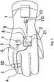
- Fig. 1 shows a top view of the arrangement of the protective glove
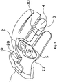
- Fig. 2 shows a view of the upper side of the protective glove
- Fig. 3 shows a detail of the interior space of the glove to accommodate a battery
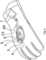
- Fig. 4 shows an exemplary embodiment of the glove according to the invention with advanced visual displaying the status
- Fig. 5 illustrates an embodiment of the glove according to the invention with a control unit, an infrared sensor, an optical pointer and an optical indicator arranged entirely under the outer layer of the glove, i.e. without a silicone protective cover.
- the invention will be described on an embodiment of a whole-textile protective glove for firefighters, which is composed of an outer layer and a system of inner layers. All the layers together ensure a synergistic effect both in terms of mechanical resistance of the glove and in terms of its thermal and heat resistance.
- the protective glove especially for firefighters, is further equipped with an electronic part, which ensures the sensing and communication functions of the glove.
- the electronic part of the glove comprises a system of sensing devices of physical quantities.
- the sensing devices are connected to a power module 1 and to a control unit 2.
- the control unit 2 is provided with a communication unit 21 of paired radio data transmission in unlicensed waveband, which is most conveniently formed by a wireless communication module with a standardized pairing and communication protocol, e.g. Bluetooth.
- the power module 1 is composed of an accumulator of electrical energy, which is provided with a connector 10, with which is aligned a connector 20 of the control unit 2, whereby the connectors 10, 20 can be repeatedly disconnected and reconnected.
- the accumulator is mounted in the inner pocket 11 of the glove, in which it is enclosed, e.g. by means of a zipper or Velcro. Most preferably, the accumulator is located on the side of the wrist of the wearer's hand in the cuff of the glove, as is apparent from Fig. 3 .
- the accumulator can be repeatedly charged by disconnecting the connectors 10 and 20, and by connecting the connector 10 to a suitable external charger, whereby the accumulator can be charged directly in the glove or after being removed from the glove.
- the accumulator is preferably of the Li-Ion type, which is a kind of technology enabling to produce tailored and thin-profile accumulators of a required capacity and output voltage, particularly accumulators capable of being charged by chargers that are readily available, e.g., by chargers for mobile phones.
- the control unit 2 is arranged in the glove in a suitable place, most suitably on the back side of the glove under at least one, but preferably by at least two layers of the glove, i.e. in the case of a whole-textile glove under at least two textile layers of the glove.
- the control unit 2 is designed as a flat plate comprising the desired electronic and electric elements to ensure the operation, including the wireless communication with pairing and communication protocol, e.g. Bluetooth, operating in unlicensed waveband from 2.4 GHz to 2.5 GHz.
- the control unit 2 is coupled to a temperature sensor 3 of the surface of the glove, which is located on the back side of one of the fingers of the glove, preferably on the back side of the ring-finger 4 of the glove, where it is relatively well protected from excessive mechanical load when this finger, i.e. the ring-finger, is being used by the user.
- the temperature sensor 3 is composed of a K type thermocouple, which is overlaid with a cap 30, made, e.g., of textile material Nomex® and is in contact with the ambient air.
- the temperatures measured by the K type thermocouple are typically in the range from -200 °C to +1250 °C.
- an infrared sensor 5 On the back side of the glove is further arranged an infrared sensor 5, which is in the illustrated example of embodiment placed in a common holder 7 with an optical pointer 6, formed, for example, by a laser diode.
- the infrared sensor 5 is able to measure remotely the temperature of a distant area, whereby it is the optical pointer 6 that enables the infrared sensor 5 to direct towards the required distant surface (potentially dangerous hot spots).
- the optical indicator 9 comprises at least one light-emitting diode (LED), most preferably an RGB LED chip with at least three colors of light - green, yellow (orange) and red.
- the optical indicator 9 at one moment signals a status detected only by one sensor.
- the optical indicator 9 also serves to indicate wireless connection to a superior unit, which may be composed of, e.g., the control unit of a smart firefighter suit or of a smart phone of the user (or of some other portable devices). It also serves to indicate the necessity to recharge the accumulator of the power module 1, etc.
- the optical indicator 9 is able to change automatically the color of its light on the basis of the instruction of the control unit 2, e.g. according to the temperature measured by the temperature sensor 3 on the glove surface, or according to the temperature of a distant surface measured by the infrared sensor 5, etc.
- the optical indicator 9 is capable of changing the color also when one of the set threshold temperatures is exceeded. The threshold temperatures are set by the user himself.
- the optical indicator 9 consisting of three color light emitting diodes - green, yellow (orange) and red, enables to signal different temperatures of the temperature being currently measured, e.g., if the measured temperature is below 100 °C, the green LED is flashing, if the measured temperature is in the range between 100 °C and 200 °C, the yellow (orange) LED blinks continuously, and if the measured temperature is above 200 °C, the red LED blinks continuously.
- the setting of the displayed threshold values can be performed independently for the measurement of the temperature TC of the surroundings of the glove by the temperature sensor 3 (thermocouple) and for the measurement of the temperature IR of a distant area by the infrared sensor 5.
- the temperatures that have been measured are transmitted through a wireless communication unit 21 by means of a standardized pairing and communication protocol to a paired common communication means (a phone, a tablet, a superior unit in a smart firefighter suit, etc.), where they are recorded and/or transmitted on-line to the incident commander of an emergency action.
- a paired common communication means a phone, a tablet, a superior unit in a smart firefighter suit, etc.
- the wireless communication unit 21 has a sufficient performance or if during the emergency action each wearer of the glove has a phone, a tablet, a computer or another communication unit paired with his gloves on him, the communication unit being set for online data transmission to the incident commander, then this data is available also to the incident commander. A more detailed analysis of the recorded data can be also performed after the emergency action.
- Figs. 4 and 5 show an exemplary embodiment of the glove according to the invention with advanced visual status display, wherein the glove comprises on its back side an optical indicator 9 created in the form of a display strip (column), which is arranged besides, or, more specifically, along a common holder 7 of the infrared sensor 5 and the optical pointer 6.
- the optical indicator 9 comprises three to ten light-emitting diodes, which are either monochromatic, or multicolored for clearer optical signaling.
- the display strip comprises five color LEDs, one of which is green, two are yellow and two are red, with the aid of which the temperatures measured by the sensors 3 and 5 are displayed more accurately and the user receives better and more accurate information.
- the control unit 2 is preferably set in such a manner that only one green diode lights at the lowest temperatures measured, at an elevated temperature always two diodes light. Due to this, the wearer can recognize more temperature stages. Thus, in the illustrated embodiment with five LEDs six temperature stages are recognized in comparison to three temperature stages in an embodiment with three LEDs having the colors of the traffic lights (green, yellow (orange), red).
- the following table shows an exemplary diagram of temperatures measured and indicated by means of five LEDs: LED TC IR from °C to °C from °C to °C green 100 100 green orange 1 100 125 100 150 orange 1 orange 2 125 150 150 200 orange 2 red 1 150 175 200 250 red 1 red 2 175 200 250 300 red 1 flashes red 2 flashes 200 300
- the glove is on its back side in the area by the switch 8 of modes provided with a separate status LED 80, which is independent of the optical indicator 9 and which by means of different types of lighting and flashing displays the accumulator charge status (charged, insufficiently charged, discharged), the status of pairing the glove with a superior electronic means (paired, unpaired, connected, unconnected), e.g., with a smart firefighter suit, a mobile phone, etc.
- the individual elements of the electronic equipment of the glove located on the back side of the glove are overlaid with a protective cover 23, which is attached to the outer layer of the glove.
- the protective cover is preferably made of a flexible material exhibiting long-term temperature resistance (to temperatures above 150 °C).
- the control unit 2, the infrared sensor 5, the optical pointer 6 and the optical indicator 9 are arranged entirely under the outer layer of the glove, i.e. are without a silicone protective cover 23.
- the glove has a longer service life and can be used at temperatures higher than those which are allowed by the protective cover 23.
- the integrated electronics is less restrictive in terms of mobility or annoying to the user, since the design of the glove closely resembles a glove without electronics.
- the entire electronic equipment i.e. the control unit 2 with the optical pointer 6 and the infrared sensor 5, is designed as one anatomically shaped unit 24, which corresponds in shape to the back side of the user's hand.
- This anatomically shaped unit 24 is directly integrated into the backside layers of the glove and is entirely overlaid with a material of the outer layer of the back side of the glove and only on the front side of this anatomically shaped unit 24 and the optical pointer 6 and the infrared sensor 5 are directed out of the glove towards the space in front of the glove.
- the material of the outer layer of the back side of the glove in the illustrated example of embodiment only comprises windows for the optical indicator 9 in the form of the above-described display strip (column) and a window for the separate status LED 80.
- the electronic equipment of the glove works in such a manner that it is put into operation by pressing the button of the switch of modes 8 disposed on the back side of the glove. With a proper connection, a charged accumulator and ambient temperatures below 100 °C, the status LED indicator lamp 80 flashes green. If the accumulator of the glove is not sufficiently charged, the status LED 8 starts to flash red.
- the electronics is switched off by a long touch of the button of the switch of modes 8. During the operation, it is possible to change the current operation mode of the electronics by a short touch on the button of the switch of modes 8.
- the electronics is set to measure the temperature by means of the temperature sensor 3 on the surface of the glove. The level of the temperature measured is indicated by the system of LEDs of the optical indicator 9.
- the electronics After pressing the button of the switch of modes 8, the electronics switches to another mode in which the temperature of distant surfaces is measured by means of the infrared sensor 5 and, at the same time, the associated optical pointer 6 is actuated.
- the level of the temperature measured is again indicated by the system of the LEDs of the optical indicator 9.
- Pairing the electronics of the glove by means of wireless communication with the control unit of a smart firefighter suit or with a smart phone of the user is carried out in such a manner that after switching on the electronics of the glove, there is an automatic attempt to pair the glove with the superior means which have been already paired before. If the glove has not been paired and at the same time the temperature being measured is below 100 °C and the accumulator is charged, the green light of the status LED 8 is flashing fast. If the glove electronic circuit has been paired and at the same time the temperature being measured is below 100 °C and the accumulator is charged, the status LED 8 is slowly flashing green.
- the electronic circuit of the glove is protected from moisture, so the glove can be routinely washed and dried.
Landscapes
- Engineering & Computer Science (AREA)
- Textile Engineering (AREA)
- Physics & Mathematics (AREA)
- Thermal Sciences (AREA)
- Life Sciences & Earth Sciences (AREA)
- Biophysics (AREA)
- Professional, Industrial, Or Sporting Protective Garments (AREA)
- Gloves (AREA)
Description
- The invention relates to a protective glove, especially for firefighters, which comprises an electronic part with a system of temperature sensing devices, which are connected to a power module and a control unit, which is coupled to a communication unit, whereby the control unit is located on the back side of the glove.
- Members of rescue services and emergency services, especially firefighters, often work in dangerous conditions that threaten their health or even lives. Beside other protective equipment, such as helmets, respiratory masks, special footwear, shields, etc., they also use special protective clothing, which is resistant not only to mechanical damage, but it is particularly resistant to heat and heat penetration to the wearer's body (the firefighter's body). This is convection heat and radiant heat. Protective clothing or garments are made of different materials and consist of different layers of materials that perform various protective functions and which result in a synergistic effect of complex protection of the wearer (the firefighter). On the other hand, the protective clothing or a garment must provide the wearer with sufficient opportunity for mobility and, if possible, give the wearer some comfort to be able to carry out their activities for the required time.
- One of the essential elements of protection, especially for firefighters, are gloves, which must provide the wearer with a sufficient level of protection and at the same time must ensure sufficient mobility of the hand and particularly the fingers.
-
EP 2407039 A2 discloses an article to be worn on the body, particularly a garment, equipped with a sensor device which can be used to monitor at least one physical and/or chemical and/or physiological property of the person wearing the object and/or to monitor the surroundings of the person and with evaluation electronics, which converts the signals of the sensor device into radio signals. This article to be worn is preferably designed as a protective glove with a sensor device, with which at least one physical and/ or chemical and/or physiological characteristic of the person wearing the protective glove and/or the person's surroundings can be detected. The evaluation electronics converts the signals of the sensor device into radio signals, which are then transmitted by means of a transmission device to a receiver for the radio signals of the protective gloves worn on the bodies of other persons, and/or to the control center. The sensor device comprises at least a temperature sensor, which measures the temperature of the surface of the person's body or which measures the temperature of the person's environment. The sensor device may also comprise an acceleration sensor, a positioning system, a barometer and/or an altitude meter, etc. Also, the glove can give an acoustic, optical and/or haptic signal. On the back side of the protective glove is integrated a temperature sensor to detect the temperature of the skin, a temperature sensor to detect the temperature of the environment, at least one sensor of acceleration and the evaluation electronics. The radio network created by the gloves is created as an "ad hoc" wireless network, through which is transmitted the data of the sensor devices of the protective gloves and/or of the control center, whereby the individual protective gloves constitute nodes of the communication network. - Other protective equipment, especially for firefighters, is known, for example, from
DE 20 2005 021140 U1 ,US 2006/022882 ,DE 100 47 533 A1 andDE 103 50 869 . - However, the disadvantage of the solution according to
EP 2 407 039 A2 is over-automation in the functioning of the glove and its electronic elements, which limit the possibilities of the firefighter in action on the scene to use at least some sensors of the glove on the basis of their personal decision while maintaining the functions of automatic monitoring the status, data transmission, etc. Another drawback is the formation of an ad-hoc wireless network, which can be affected by radio interference around the area of the emergency action, where everyone communicates with everyone else. What is more, such ad-hoc networks are not, as a rule, secured against attacks, etc. Moreover, the disadvantage of the described solution is the fact that only the temperature in the immediate vicinity of the glove is measured and the solution in no way allows the measurement of the temperature of the distant objects. The method of displaying the measured temperatures is not described in the invention, nor is described the specific technical solution of displaying the data. -
FR2882433 WO9314472 - The goal of the invention is to remove or at least to minimize the disadvantages of the background art.
- The goal of the invention is achieved by a protective glove, especially for firefighters, whose principle consists in that one temperature sensing device is a temperature sensor of the glove surface, located on the back side of one of the fingers of the glove, and a second temperature sensing device is an infrared sensor, arranged on the back side of the glove along with an optical pointer which is assigned to it, whereby on the back side of the glove is further disposed a switch of operation modes of the glove electronics and a color optical indicator showing the temperature, the glove status or the operation mode of the electronics of the glove, wherein both the switch of modes and the color optical indicator are connected to a control unit.
- The advantage of the protective glove according to the invention is a high degree of protection it provides despite the incorporated electronic elements, which are, however, universally and easily exploitable and whose information is displayed directly on the glove in a very simple and clear manner. At the same time, the glove is capable of providing information about temperatures directly to the user on the scene without the need for another display device, as well as to a remote observer, e.g., the commander of the emergency action, etc. Simultaneously, the data showing the temperature development is automatically stored. Another advantage of this solution is the fact that the glove enables to measure the temperature of distant areas. This solution also enables to create a glove which is easily washable by ordinary washing means (a common washing machine and an ordinary detergent). Another advantage is the fact that by integrating all the electronic and mechanical parts directly into the design of the glove, the glove is safe because the incorporated electronics and other elements do not protrude through anywhere and do not get caught. The electronics and other elements do not interfere with the use of gloves even in challenging conditions. Another advantage of this solution is the fact that the glove can be used either alone or in combination with a superior system, e.g. a smart firefighter suit, etc. Another indisputable benefit is easy data transmission to common communication means, such as smart phones, and then through them on to the internet (cloud solutions and the like), which allows to record and analyze data, etc. Another advantage is the fact that the glove user can set the limits of signaling (e.g. changing signaling colors, etc.) according to their own preferences and needs.
- The invention is schematically represented in the drawing, where
Fig. 1 shows a top view of the arrangement of the protective glove,Fig. 2 shows a view of the upper side of the protective glove,Fig. 3 shows a detail of the interior space of the glove to accommodate a battery,Fig. 4 shows an exemplary embodiment of the glove according to the invention with advanced visual displaying the status andFig. 5 illustrates an embodiment of the glove according to the invention with a control unit, an infrared sensor, an optical pointer and an optical indicator arranged entirely under the outer layer of the glove, i.e. without a silicone protective cover. - The invention will be described on an embodiment of a whole-textile protective glove for firefighters, which is composed of an outer layer and a system of inner layers. All the layers together ensure a synergistic effect both in terms of mechanical resistance of the glove and in terms of its thermal and heat resistance.
- The protective glove, especially for firefighters, is further equipped with an electronic part, which ensures the sensing and communication functions of the glove. The electronic part of the glove comprises a system of sensing devices of physical quantities. The sensing devices are connected to a power module 1 and to a
control unit 2. Thecontrol unit 2 is provided with acommunication unit 21 of paired radio data transmission in unlicensed waveband, which is most conveniently formed by a wireless communication module with a standardized pairing and communication protocol, e.g. Bluetooth. - The power module 1 is composed of an accumulator of electrical energy, which is provided with a
connector 10, with which is aligned aconnector 20 of thecontrol unit 2, whereby theconnectors inner pocket 11 of the glove, in which it is enclosed, e.g. by means of a zipper or Velcro. Most preferably, the accumulator is located on the side of the wrist of the wearer's hand in the cuff of the glove, as is apparent fromFig. 3 . The accumulator can be repeatedly charged by disconnecting theconnectors connector 10 to a suitable external charger, whereby the accumulator can be charged directly in the glove or after being removed from the glove. The accumulator is preferably of the Li-Ion type, which is a kind of technology enabling to produce tailored and thin-profile accumulators of a required capacity and output voltage, particularly accumulators capable of being charged by chargers that are readily available, e.g., by chargers for mobile phones. - The
control unit 2 is arranged in the glove in a suitable place, most suitably on the back side of the glove under at least one, but preferably by at least two layers of the glove, i.e. in the case of a whole-textile glove under at least two textile layers of the glove. Thecontrol unit 2 is designed as a flat plate comprising the desired electronic and electric elements to ensure the operation, including the wireless communication with pairing and communication protocol, e.g. Bluetooth, operating in unlicensed waveband from 2.4 GHz to 2.5 GHz. - The
control unit 2 is coupled to atemperature sensor 3 of the surface of the glove, which is located on the back side of one of the fingers of the glove, preferably on the back side of the ring-finger 4 of the glove, where it is relatively well protected from excessive mechanical load when this finger, i.e. the ring-finger, is being used by the user. Thetemperature sensor 3 is composed of a K type thermocouple, which is overlaid with acap 30, made, e.g., of textile material Nomex® and is in contact with the ambient air. The temperatures measured by the K type thermocouple are typically in the range from -200 °C to +1250 °C. - On the back side of the glove is further arranged an
infrared sensor 5, which is in the illustrated example of embodiment placed in acommon holder 7 with anoptical pointer 6, formed, for example, by a laser diode. Theinfrared sensor 5 is able to measure remotely the temperature of a distant area, whereby it is theoptical pointer 6 that enables theinfrared sensor 5 to direct towards the required distant surface (potentially dangerous hot spots). - On the back side of the glove is further arranged a
switch 8 of operation modes of the electronics of the glove and anoptical indicator 9 of the temperature, the status of the glove or the mode of operation of the electronics of the glove. Both theswitch 8 of modes and theoptical indicator 9 are connected to thecontrol unit 2, which ensures their power supply and function. For example, theoptical indicator 9 comprises at least one light-emitting diode (LED), most preferably an RGB LED chip with at least three colors of light - green, yellow (orange) and red. In a preferred embodiment, theoptical indicator 9 at one moment signals a status detected only by one sensor. Theoptical indicator 9 also serves to indicate wireless connection to a superior unit, which may be composed of, e.g., the control unit of a smart firefighter suit or of a smart phone of the user (or of some other portable devices). It also serves to indicate the necessity to recharge the accumulator of the power module 1, etc. Thus, theoptical indicator 9 is able to change automatically the color of its light on the basis of the instruction of thecontrol unit 2, e.g. according to the temperature measured by thetemperature sensor 3 on the glove surface, or according to the temperature of a distant surface measured by theinfrared sensor 5, etc. Optionally, theoptical indicator 9 is capable of changing the color also when one of the set threshold temperatures is exceeded. The threshold temperatures are set by the user himself. - The
optical indicator 9, consisting of three color light emitting diodes - green, yellow (orange) and red, enables to signal different temperatures of the temperature being currently measured, e.g., if the measured temperature is below 100 °C, the green LED is flashing, if the measured temperature is in the range between 100 °C and 200 °C, the yellow (orange) LED blinks continuously, and if the measured temperature is above 200 °C, the red LED blinks continuously. The setting of the displayed threshold values can be performed independently for the measurement of the temperature TC of the surroundings of the glove by the temperature sensor 3 (thermocouple) and for the measurement of the temperature IR of a distant area by theinfrared sensor 5. - The temperatures that have been measured, whether these are the temperatures of a distant area measured by the
infrared sensor 5, or the temperatures in the surroundings of the glove measured by thetemperature sensor 3 on the glove surface, are transmitted through awireless communication unit 21 by means of a standardized pairing and communication protocol to a paired common communication means (a phone, a tablet, a superior unit in a smart firefighter suit, etc.), where they are recorded and/or transmitted on-line to the incident commander of an emergency action. These recorded and transmitted temperatures are temperatures that have been actually measured, which means that this is not just a record of the occurrence of limit values, but a record of the course of temperatures throughout the emergency action. If thewireless communication unit 21, has a sufficient performance or if during the emergency action each wearer of the glove has a phone, a tablet, a computer or another communication unit paired with his gloves on him, the communication unit being set for online data transmission to the incident commander, then this data is available also to the incident commander. A more detailed analysis of the recorded data can be also performed after the emergency action. -
Figs. 4 and5 show an exemplary embodiment of the glove according to the invention with advanced visual status display, wherein the glove comprises on its back side anoptical indicator 9 created in the form of a display strip (column), which is arranged besides, or, more specifically, along acommon holder 7 of theinfrared sensor 5 and theoptical pointer 6. Theoptical indicator 9 comprises three to ten light-emitting diodes, which are either monochromatic, or multicolored for clearer optical signaling. In the illustrated example of embodiment, the display strip comprises five color LEDs, one of which is green, two are yellow and two are red, with the aid of which the temperatures measured by thesensors control unit 2 is preferably set in such a manner that only one green diode lights at the lowest temperatures measured, at an elevated temperature always two diodes light. Due to this, the wearer can recognize more temperature stages. Thus, in the illustrated embodiment with five LEDs six temperature stages are recognized in comparison to three temperature stages in an embodiment with three LEDs having the colors of the traffic lights (green, yellow (orange), red). The following table shows an exemplary diagram of temperatures measured and indicated by means of five LEDs:LED TC IR from °C to °C from °C to °C green 100 100 green orange 1 100 125 100 150 orange 1 orange 2125 150 150 200 orange 2red 1 150 175 200 250 red 1 red 2 175 200 250 300 red 1 flashes red 2 flashes 200 300 - In the embodiment in
Fig. 4 , the glove is on its back side in the area by theswitch 8 of modes provided with aseparate status LED 80, which is independent of theoptical indicator 9 and which by means of different types of lighting and flashing displays the accumulator charge status (charged, insufficiently charged, discharged), the status of pairing the glove with a superior electronic means (paired, unpaired, connected, unconnected), e.g., with a smart firefighter suit, a mobile phone, etc. - In the examples of embodiment in
Figs. 1 to 4 , the individual elements of the electronic equipment of the glove located on the back side of the glove are overlaid with aprotective cover 23, which is attached to the outer layer of the glove. The protective cover is preferably made of a flexible material exhibiting long-term temperature resistance (to temperatures above 150 °C). - In the embodiment in
Fig. 5 , thecontrol unit 2, theinfrared sensor 5, theoptical pointer 6 and theoptical indicator 9 are arranged entirely under the outer layer of the glove, i.e. are without a siliconeprotective cover 23. As a result, the glove has a longer service life and can be used at temperatures higher than those which are allowed by theprotective cover 23. In addition, the integrated electronics is less restrictive in terms of mobility or annoying to the user, since the design of the glove closely resembles a glove without electronics. In this exemplary embodiment, the entire electronic equipment, i.e. thecontrol unit 2 with theoptical pointer 6 and theinfrared sensor 5, is designed as one anatomicallyshaped unit 24, which corresponds in shape to the back side of the user's hand. This anatomicallyshaped unit 24 is directly integrated into the backside layers of the glove and is entirely overlaid with a material of the outer layer of the back side of the glove and only on the front side of this anatomically shapedunit 24 and theoptical pointer 6 and theinfrared sensor 5 are directed out of the glove towards the space in front of the glove. The material of the outer layer of the back side of the glove in the illustrated example of embodiment only comprises windows for theoptical indicator 9 in the form of the above-described display strip (column) and a window for theseparate status LED 80. In an unillustrated example of embodiment, in the seam of the index finger edge (or in another seam) of the glove are led out at least three side-emitting fiber optic links (green, yellow (orange), red), which bring the light of the LED of theoptical indicator 9 from the inside of the glove to the surface of the glove. - The electronic equipment of the glove works in such a manner that it is put into operation by pressing the button of the switch of
modes 8 disposed on the back side of the glove. With a proper connection, a charged accumulator and ambient temperatures below 100 °C, the statusLED indicator lamp 80 flashes green. If the accumulator of the glove is not sufficiently charged, thestatus LED 8 starts to flash red. The electronics is switched off by a long touch of the button of the switch ofmodes 8. During the operation, it is possible to change the current operation mode of the electronics by a short touch on the button of the switch ofmodes 8. In the basic operation mode, the electronics is set to measure the temperature by means of thetemperature sensor 3 on the surface of the glove. The level of the temperature measured is indicated by the system of LEDs of theoptical indicator 9. After pressing the button of the switch ofmodes 8, the electronics switches to another mode in which the temperature of distant surfaces is measured by means of theinfrared sensor 5 and, at the same time, the associatedoptical pointer 6 is actuated. The level of the temperature measured is again indicated by the system of the LEDs of theoptical indicator 9. Pairing the electronics of the glove by means of wireless communication with the control unit of a smart firefighter suit or with a smart phone of the user is carried out in such a manner that after switching on the electronics of the glove, there is an automatic attempt to pair the glove with the superior means which have been already paired before. If the glove has not been paired and at the same time the temperature being measured is below 100 °C and the accumulator is charged, the green light of thestatus LED 8 is flashing fast. If the glove electronic circuit has been paired and at the same time the temperature being measured is below 100 °C and the accumulator is charged, thestatus LED 8 is slowly flashing green. - The electronic circuit of the glove is protected from moisture, so the glove can be routinely washed and dried.
Claims (10)
- A protective glove, especially for firefighters, which comprises an electronic part with a system of temperature sensor devices (3, 5), which are connected to a power module (1) and to a control unit (2), which is coupled to a communication unit (21), whereby the control unit (2) is located on the back side of the glove, wherein one sensor device of the temperature is a temperature sensor (3) of the glove surface, which is located on the back side of one of the fingers of the glove, whereby on the back side of the glove is further arranged a switch (8) of operation modes of the glove electronics and an optical indicator (9) of the temperature, status of the glove or operation mode of the glove electronics, wherein both the switch (8) of modes and the optical indicator (9) are connected to the control unit (2), the protective glove is characterized in that a second sensor device of the temperature is an infrared sensor (5), which is along with an optical pointer (6) arranged on the back side of the glove.
- The protective glove according to claim 1, characterized in that the infrared sensor (5) and the optical pointer (6) are arranged in a common case (7).
- The protective glove according to claim 1, characterized in that the optical indicator (9) comprises at least one light-emitting diode.
- The protective glove according to claim 3, characterized in that the optical indicator (9) comprises a display strip with two to ten light-emitting diodes.
- The protective glove according to claim 1, characterized in that the temperature sensor (3) is composed of a thermocouple, which is overlaid with a protective cap (30) and is in contact with the ambient air.
- The protective glove according to claim 1, characterized in that the control unit (2) is coupled to a wireless communication unit (21) with a pairing and communication protocol for transmitting and recording the measured values on the paired device.
- The protective glove according to claim 1, characterized in that on the back side of the glove is disposed a separate status light-emitting diode (80), which is independent of the optical indicator (9) and is used for displaying the status of the glove electronics.
- The protective glove according to any of claims 1 to 7, characterized in that the infrared sensor (5), the optical pointer (6), the switch (8) of modes, the optical indicator (9) of the temperature and the status light-emitting diode on the back side of the glove are overlaid with a protective cover (23), which is attached to the outer layer of the glove.
- The protective glove according to any of claims 1 to 8, characterized in that the infrared sensor (5), the optical pointer (6), the switch (8) of modes, the optical indicator (9) of the temperature and the status light-emitting diode on the back side of the glove are arranged completely under the outer layer of the glove.
- The protective glove according to claim 9, characterized in that optical indication is performed by fiber optic links, which are arranged on the surface of the glove.
Priority Applications (1)
| Application Number | Priority Date | Filing Date | Title |
|---|---|---|---|
| EP16195711.3A EP3315037B1 (en) | 2016-10-26 | 2016-10-26 | Protective glove, especially for firefighters |
Applications Claiming Priority (1)
| Application Number | Priority Date | Filing Date | Title |
|---|---|---|---|
| EP16195711.3A EP3315037B1 (en) | 2016-10-26 | 2016-10-26 | Protective glove, especially for firefighters |
Publications (2)
| Publication Number | Publication Date |
|---|---|
| EP3315037A1 EP3315037A1 (en) | 2018-05-02 |
| EP3315037B1 true EP3315037B1 (en) | 2019-08-14 |
Family
ID=57569864
Family Applications (1)
| Application Number | Title | Priority Date | Filing Date |
|---|---|---|---|
| EP16195711.3A Active EP3315037B1 (en) | 2016-10-26 | 2016-10-26 | Protective glove, especially for firefighters |
Country Status (1)
| Country | Link |
|---|---|
| EP (1) | EP3315037B1 (en) |
Cited By (1)
| Publication number | Priority date | Publication date | Assignee | Title |
|---|---|---|---|---|
| WO2023044202A1 (en) | 2021-09-20 | 2023-03-23 | Dupont Safety & Construction, Inc. | Protective glove |
Families Citing this family (3)
| Publication number | Priority date | Publication date | Assignee | Title |
|---|---|---|---|---|
| US11326960B2 (en) * | 2017-08-09 | 2022-05-10 | Honeywell International Inc. | Standoff temperature measurement for first responders |
| KR102475353B1 (en) * | 2020-10-08 | 2022-12-07 | 서울특별시 | Glove for fire fighting with temperature sensor |
| US20220125139A1 (en) * | 2020-10-26 | 2022-04-28 | Jahmal Averyhart | Customizable Oven Mitt with a Temperature Sensor and Speaker |
Citations (2)
| Publication number | Priority date | Publication date | Assignee | Title |
|---|---|---|---|---|
| WO1993014472A1 (en) * | 1992-01-16 | 1993-07-22 | Metrologic Instruments, Inc. | Hands-free body mounted laser scanner and method of use |
| FR2882433A1 (en) * | 2005-02-22 | 2006-08-25 | Bernard Jacquinot | Temperature detection device for use with firemen helmet, has luminous type warning unit disposed laterally of device and triggered automatically when predetermined temperature threshold is attained |
Family Cites Families (11)
| Publication number | Priority date | Publication date | Assignee | Title |
|---|---|---|---|---|
| DE9401951U1 (en) * | 1994-02-05 | 1994-03-24 | Schmidberger Wolfgang | Outer garment, such as glove or shoe |
| NL1011804C2 (en) * | 1999-04-15 | 2000-10-17 | Skf Engineering & Res Services | Detection system and use thereof. |
| DE10047533A1 (en) | 2000-09-21 | 2002-04-11 | Deutsche Telekom Ag | Intelligent clothing item provided with sensor e.g. for monitoring vital functions of wearer, has sensor electrical line acting as antenna |
| DE10350869A1 (en) | 2003-10-31 | 2005-06-09 | Infineon Technologies Ag | Garment e.g. sport trouser, for use by athlete, has sensor, actuator and indicator, coupled by thin conductor threads, inserted in canvas of garment, where indicator and/or actuator convey message to athlete for correcting body posture |
| DE102004036878B4 (en) | 2004-07-29 | 2008-04-10 | Dräger Safety AG & Co. KGaA | Method and device for radio transmission of signals generated close to the body |
| DE202005021140U1 (en) | 2005-11-14 | 2007-08-09 | Sächsisches Textilforschungsinstitut e.V. | Multifunctional sensor integrated clothing system |
| WO2009111397A2 (en) * | 2008-03-04 | 2009-09-11 | Denise Lynn Merkle | Temperature sensing glove for automotive applications |
| GB2460430B (en) * | 2008-05-29 | 2012-02-15 | Gary Russell Howes | Wearable temperature sensor |
| DE202010004348U1 (en) * | 2010-03-30 | 2010-06-24 | Corsten, Eva | Temperature monitoring device and children's clothing equipped therewith |
| DE102010027405A1 (en) | 2010-07-15 | 2012-01-19 | W + R Gmbh | An article to be worn on the body, in particular a garment |
| KR20150001872U (en) * | 2013-11-08 | 2015-05-18 | 대우조선해양 주식회사 | Gloves with burns prevention module |
-
2016
- 2016-10-26 EP EP16195711.3A patent/EP3315037B1/en active Active
Patent Citations (2)
| Publication number | Priority date | Publication date | Assignee | Title |
|---|---|---|---|---|
| WO1993014472A1 (en) * | 1992-01-16 | 1993-07-22 | Metrologic Instruments, Inc. | Hands-free body mounted laser scanner and method of use |
| FR2882433A1 (en) * | 2005-02-22 | 2006-08-25 | Bernard Jacquinot | Temperature detection device for use with firemen helmet, has luminous type warning unit disposed laterally of device and triggered automatically when predetermined temperature threshold is attained |
Cited By (1)
| Publication number | Priority date | Publication date | Assignee | Title |
|---|---|---|---|---|
| WO2023044202A1 (en) | 2021-09-20 | 2023-03-23 | Dupont Safety & Construction, Inc. | Protective glove |
Also Published As
| Publication number | Publication date |
|---|---|
| EP3315037A1 (en) | 2018-05-02 |
Similar Documents
| Publication | Publication Date | Title |
|---|---|---|
| EP3315037B1 (en) | Protective glove, especially for firefighters | |
| KR102517353B1 (en) | Wearable article with detachable module | |
| CN109196356A (en) | Ke Laizidaier detector | |
| JP6874279B2 (en) | Radio wave shielding device in wearable devices | |
| KR200475404Y1 (en) | Smart Clothing | |
| GB2591820A (en) | Wearable article | |
| KR102511038B1 (en) | Clip-type body temperature indicating device for checking fever | |
| CZ30242U1 (en) | Protective gloves, especially for firefighters | |
| KR102045935B1 (en) | Clothes with monitoring and protecting function | |
| GB2593434A (en) | Electronics arrangement for a wearable article | |
| GB2590986A (en) | Electronics arrangement for a wearable article | |
| GB2590985A (en) | Electronics arrangement for a wearable article | |
| GB2593433A (en) | Electronics arrangement for a wearable article | |
| GB2591819A (en) | Electronics arrangement for a wearable article | |
| KR20170080774A (en) | A Helmet Cap | |
| CN206019873U (en) | A kind of fire-entry suit with temperature alarming function | |
| TWM466639U (en) | Heat stroke detector | |
| CN109922282B (en) | Thermal imaging camera and thermal imaging camera system | |
| CN112220126A (en) | Novel but gauze mask of real-time detection body temperature | |
| GB2591821A (en) | Wearable article | |
| US9982880B2 (en) | Table lamp with emergency escape function | |
| CN215075726U (en) | Clothes capable of monitoring body temperature in real time | |
| CN216309272U (en) | Wearable body temperature measuring device and body temperature measuring system | |
| CN213041382U (en) | Body temperature monitoring device fixed on edge of helmet or hat | |
| CN215737096U (en) | Fire control temperature measurement gloves |
Legal Events
| Date | Code | Title | Description |
|---|---|---|---|
| PUAI | Public reference made under article 153(3) epc to a published international application that has entered the european phase |
Free format text: ORIGINAL CODE: 0009012 |
|
| STAA | Information on the status of an ep patent application or granted ep patent |
Free format text: STATUS: THE APPLICATION HAS BEEN PUBLISHED |
|
| AK | Designated contracting states |
Kind code of ref document: A1 Designated state(s): AL AT BE BG CH CY CZ DE DK EE ES FI FR GB GR HR HU IE IS IT LI LT LU LV MC MK MT NL NO PL PT RO RS SE SI SK SM TR |
|
| AX | Request for extension of the european patent |
Extension state: BA ME |
|
| STAA | Information on the status of an ep patent application or granted ep patent |
Free format text: STATUS: REQUEST FOR EXAMINATION WAS MADE |
|
| 17P | Request for examination filed |
Effective date: 20181030 |
|
| RBV | Designated contracting states (corrected) |
Designated state(s): AL AT BE BG CH CY CZ DE DK EE ES FI FR GB GR HR HU IE IS IT LI LT LU LV MC MK MT NL NO PL PT RO RS SE SI SK SM TR |
|
| REG | Reference to a national code |
Ref country code: DE Ref legal event code: R079 Ref document number: 602016018504 Country of ref document: DE Free format text: PREVIOUS MAIN CLASS: A41D0001000000 Ipc: G01S0017080000 |
|
| GRAP | Despatch of communication of intention to grant a patent |
Free format text: ORIGINAL CODE: EPIDOSNIGR1 |
|
| STAA | Information on the status of an ep patent application or granted ep patent |
Free format text: STATUS: GRANT OF PATENT IS INTENDED |
|
| RIC1 | Information provided on ipc code assigned before grant |
Ipc: G01S 17/08 20060101AFI20190327BHEP Ipc: A41D 19/015 20060101ALI20190327BHEP |
|
| INTG | Intention to grant announced |
Effective date: 20190415 |
|
| GRAS | Grant fee paid |
Free format text: ORIGINAL CODE: EPIDOSNIGR3 |
|
| GRAA | (expected) grant |
Free format text: ORIGINAL CODE: 0009210 |
|
| STAA | Information on the status of an ep patent application or granted ep patent |
Free format text: STATUS: THE PATENT HAS BEEN GRANTED |
|
| AK | Designated contracting states |
Kind code of ref document: B1 Designated state(s): AL AT BE BG CH CY CZ DE DK EE ES FI FR GB GR HR HU IE IS IT LI LT LU LV MC MK MT NL NO PL PT RO RS SE SI SK SM TR |
|
| REG | Reference to a national code |
Ref country code: GB Ref legal event code: FG4D |
|
| REG | Reference to a national code |
Ref country code: CH Ref legal event code: EP Ref country code: AT Ref legal event code: REF Ref document number: 1167691 Country of ref document: AT Kind code of ref document: T Effective date: 20190815 |
|
| REG | Reference to a national code |
Ref country code: IE Ref legal event code: FG4D |
|
| REG | Reference to a national code |
Ref country code: DE Ref legal event code: R096 Ref document number: 602016018504 Country of ref document: DE |
|
| REG | Reference to a national code |
Ref country code: NL Ref legal event code: MP Effective date: 20190814 |
|
| REG | Reference to a national code |
Ref country code: LT Ref legal event code: MG4D |
|
| PG25 | Lapsed in a contracting state [announced via postgrant information from national office to epo] |
Ref country code: HR Free format text: LAPSE BECAUSE OF FAILURE TO SUBMIT A TRANSLATION OF THE DESCRIPTION OR TO PAY THE FEE WITHIN THE PRESCRIBED TIME-LIMIT Effective date: 20190814 Ref country code: LT Free format text: LAPSE BECAUSE OF FAILURE TO SUBMIT A TRANSLATION OF THE DESCRIPTION OR TO PAY THE FEE WITHIN THE PRESCRIBED TIME-LIMIT Effective date: 20190814 Ref country code: NO Free format text: LAPSE BECAUSE OF FAILURE TO SUBMIT A TRANSLATION OF THE DESCRIPTION OR TO PAY THE FEE WITHIN THE PRESCRIBED TIME-LIMIT Effective date: 20191114 Ref country code: FI Free format text: LAPSE BECAUSE OF FAILURE TO SUBMIT A TRANSLATION OF THE DESCRIPTION OR TO PAY THE FEE WITHIN THE PRESCRIBED TIME-LIMIT Effective date: 20190814 Ref country code: SE Free format text: LAPSE BECAUSE OF FAILURE TO SUBMIT A TRANSLATION OF THE DESCRIPTION OR TO PAY THE FEE WITHIN THE PRESCRIBED TIME-LIMIT Effective date: 20190814 Ref country code: PT Free format text: LAPSE BECAUSE OF FAILURE TO SUBMIT A TRANSLATION OF THE DESCRIPTION OR TO PAY THE FEE WITHIN THE PRESCRIBED TIME-LIMIT Effective date: 20191216 Ref country code: BG Free format text: LAPSE BECAUSE OF FAILURE TO SUBMIT A TRANSLATION OF THE DESCRIPTION OR TO PAY THE FEE WITHIN THE PRESCRIBED TIME-LIMIT Effective date: 20191114 Ref country code: NL Free format text: LAPSE BECAUSE OF FAILURE TO SUBMIT A TRANSLATION OF THE DESCRIPTION OR TO PAY THE FEE WITHIN THE PRESCRIBED TIME-LIMIT Effective date: 20190814 |
|
| PG25 | Lapsed in a contracting state [announced via postgrant information from national office to epo] |
Ref country code: RS Free format text: LAPSE BECAUSE OF FAILURE TO SUBMIT A TRANSLATION OF THE DESCRIPTION OR TO PAY THE FEE WITHIN THE PRESCRIBED TIME-LIMIT Effective date: 20190814 Ref country code: IS Free format text: LAPSE BECAUSE OF FAILURE TO SUBMIT A TRANSLATION OF THE DESCRIPTION OR TO PAY THE FEE WITHIN THE PRESCRIBED TIME-LIMIT Effective date: 20191214 Ref country code: LV Free format text: LAPSE BECAUSE OF FAILURE TO SUBMIT A TRANSLATION OF THE DESCRIPTION OR TO PAY THE FEE WITHIN THE PRESCRIBED TIME-LIMIT Effective date: 20190814 Ref country code: GR Free format text: LAPSE BECAUSE OF FAILURE TO SUBMIT A TRANSLATION OF THE DESCRIPTION OR TO PAY THE FEE WITHIN THE PRESCRIBED TIME-LIMIT Effective date: 20191115 Ref country code: ES Free format text: LAPSE BECAUSE OF FAILURE TO SUBMIT A TRANSLATION OF THE DESCRIPTION OR TO PAY THE FEE WITHIN THE PRESCRIBED TIME-LIMIT Effective date: 20190814 Ref country code: AL Free format text: LAPSE BECAUSE OF FAILURE TO SUBMIT A TRANSLATION OF THE DESCRIPTION OR TO PAY THE FEE WITHIN THE PRESCRIBED TIME-LIMIT Effective date: 20190814 |
|
| PG25 | Lapsed in a contracting state [announced via postgrant information from national office to epo] |
Ref country code: TR Free format text: LAPSE BECAUSE OF FAILURE TO SUBMIT A TRANSLATION OF THE DESCRIPTION OR TO PAY THE FEE WITHIN THE PRESCRIBED TIME-LIMIT Effective date: 20190814 |
|
| PG25 | Lapsed in a contracting state [announced via postgrant information from national office to epo] |
Ref country code: PL Free format text: LAPSE BECAUSE OF FAILURE TO SUBMIT A TRANSLATION OF THE DESCRIPTION OR TO PAY THE FEE WITHIN THE PRESCRIBED TIME-LIMIT Effective date: 20190814 Ref country code: RO Free format text: LAPSE BECAUSE OF FAILURE TO SUBMIT A TRANSLATION OF THE DESCRIPTION OR TO PAY THE FEE WITHIN THE PRESCRIBED TIME-LIMIT Effective date: 20190814 Ref country code: EE Free format text: LAPSE BECAUSE OF FAILURE TO SUBMIT A TRANSLATION OF THE DESCRIPTION OR TO PAY THE FEE WITHIN THE PRESCRIBED TIME-LIMIT Effective date: 20190814 Ref country code: DK Free format text: LAPSE BECAUSE OF FAILURE TO SUBMIT A TRANSLATION OF THE DESCRIPTION OR TO PAY THE FEE WITHIN THE PRESCRIBED TIME-LIMIT Effective date: 20190814 Ref country code: IT Free format text: LAPSE BECAUSE OF FAILURE TO SUBMIT A TRANSLATION OF THE DESCRIPTION OR TO PAY THE FEE WITHIN THE PRESCRIBED TIME-LIMIT Effective date: 20190814 |
|
| PG25 | Lapsed in a contracting state [announced via postgrant information from national office to epo] |
Ref country code: IS Free format text: LAPSE BECAUSE OF FAILURE TO SUBMIT A TRANSLATION OF THE DESCRIPTION OR TO PAY THE FEE WITHIN THE PRESCRIBED TIME-LIMIT Effective date: 20200224 Ref country code: SM Free format text: LAPSE BECAUSE OF FAILURE TO SUBMIT A TRANSLATION OF THE DESCRIPTION OR TO PAY THE FEE WITHIN THE PRESCRIBED TIME-LIMIT Effective date: 20190814 Ref country code: CZ Free format text: LAPSE BECAUSE OF FAILURE TO SUBMIT A TRANSLATION OF THE DESCRIPTION OR TO PAY THE FEE WITHIN THE PRESCRIBED TIME-LIMIT Effective date: 20190814 Ref country code: MC Free format text: LAPSE BECAUSE OF FAILURE TO SUBMIT A TRANSLATION OF THE DESCRIPTION OR TO PAY THE FEE WITHIN THE PRESCRIBED TIME-LIMIT Effective date: 20190814 Ref country code: SK Free format text: LAPSE BECAUSE OF FAILURE TO SUBMIT A TRANSLATION OF THE DESCRIPTION OR TO PAY THE FEE WITHIN THE PRESCRIBED TIME-LIMIT Effective date: 20190814 |
|
| REG | Reference to a national code |
Ref country code: CH Ref legal event code: PL |
|
| REG | Reference to a national code |
Ref country code: DE Ref legal event code: R097 Ref document number: 602016018504 Country of ref document: DE |
|
| PLBE | No opposition filed within time limit |
Free format text: ORIGINAL CODE: 0009261 |
|
| STAA | Information on the status of an ep patent application or granted ep patent |
Free format text: STATUS: NO OPPOSITION FILED WITHIN TIME LIMIT |
|
| PG2D | Information on lapse in contracting state deleted |
Ref country code: IS |
|
| PG25 | Lapsed in a contracting state [announced via postgrant information from national office to epo] |
Ref country code: LU Free format text: LAPSE BECAUSE OF NON-PAYMENT OF DUE FEES Effective date: 20191026 Ref country code: CH Free format text: LAPSE BECAUSE OF NON-PAYMENT OF DUE FEES Effective date: 20191031 Ref country code: LI Free format text: LAPSE BECAUSE OF NON-PAYMENT OF DUE FEES Effective date: 20191031 |
|
| 26N | No opposition filed |
Effective date: 20200603 |
|
| REG | Reference to a national code |
Ref country code: BE Ref legal event code: MM Effective date: 20191031 |
|
| PG25 | Lapsed in a contracting state [announced via postgrant information from national office to epo] |
Ref country code: BE Free format text: LAPSE BECAUSE OF NON-PAYMENT OF DUE FEES Effective date: 20191031 Ref country code: SI Free format text: LAPSE BECAUSE OF FAILURE TO SUBMIT A TRANSLATION OF THE DESCRIPTION OR TO PAY THE FEE WITHIN THE PRESCRIBED TIME-LIMIT Effective date: 20190814 |
|
| REG | Reference to a national code |
Ref country code: AT Ref legal event code: UEP Ref document number: 1167691 Country of ref document: AT Kind code of ref document: T Effective date: 20190814 |
|
| PG25 | Lapsed in a contracting state [announced via postgrant information from national office to epo] |
Ref country code: IE Free format text: LAPSE BECAUSE OF NON-PAYMENT OF DUE FEES Effective date: 20191026 |
|
| PG25 | Lapsed in a contracting state [announced via postgrant information from national office to epo] |
Ref country code: CY Free format text: LAPSE BECAUSE OF FAILURE TO SUBMIT A TRANSLATION OF THE DESCRIPTION OR TO PAY THE FEE WITHIN THE PRESCRIBED TIME-LIMIT Effective date: 20190814 |
|
| GBPC | Gb: european patent ceased through non-payment of renewal fee |
Effective date: 20201026 |
|
| PG25 | Lapsed in a contracting state [announced via postgrant information from national office to epo] |
Ref country code: MT Free format text: LAPSE BECAUSE OF FAILURE TO SUBMIT A TRANSLATION OF THE DESCRIPTION OR TO PAY THE FEE WITHIN THE PRESCRIBED TIME-LIMIT Effective date: 20190814 Ref country code: HU Free format text: LAPSE BECAUSE OF FAILURE TO SUBMIT A TRANSLATION OF THE DESCRIPTION OR TO PAY THE FEE WITHIN THE PRESCRIBED TIME-LIMIT; INVALID AB INITIO Effective date: 20161026 |
|
| PG25 | Lapsed in a contracting state [announced via postgrant information from national office to epo] |
Ref country code: GB Free format text: LAPSE BECAUSE OF NON-PAYMENT OF DUE FEES Effective date: 20201026 |
|
| PGFP | Annual fee paid to national office [announced via postgrant information from national office to epo] |
Ref country code: AT Payment date: 20210929 Year of fee payment: 6 |
|
| PG25 | Lapsed in a contracting state [announced via postgrant information from national office to epo] |
Ref country code: MK Free format text: LAPSE BECAUSE OF FAILURE TO SUBMIT A TRANSLATION OF THE DESCRIPTION OR TO PAY THE FEE WITHIN THE PRESCRIBED TIME-LIMIT Effective date: 20190814 |
|
| PGFP | Annual fee paid to national office [announced via postgrant information from national office to epo] |
Ref country code: FR Payment date: 20221020 Year of fee payment: 7 |
|
| PGFP | Annual fee paid to national office [announced via postgrant information from national office to epo] |
Ref country code: DE Payment date: 20221027 Year of fee payment: 7 |
|
| REG | Reference to a national code |
Ref country code: AT Ref legal event code: MM01 Ref document number: 1167691 Country of ref document: AT Kind code of ref document: T Effective date: 20221026 |
|
| PG25 | Lapsed in a contracting state [announced via postgrant information from national office to epo] |
Ref country code: AT Free format text: LAPSE BECAUSE OF NON-PAYMENT OF DUE FEES Effective date: 20221026 |
|
| P01 | Opt-out of the competence of the unified patent court (upc) registered |
Effective date: 20230821 |