EP3312762A1 - Method and system for tracking an object in a defined area - Google Patents
Method and system for tracking an object in a defined area Download PDFInfo
- Publication number
- EP3312762A1 EP3312762A1 EP16194411.1A EP16194411A EP3312762A1 EP 3312762 A1 EP3312762 A1 EP 3312762A1 EP 16194411 A EP16194411 A EP 16194411A EP 3312762 A1 EP3312762 A1 EP 3312762A1
- Authority
- EP
- European Patent Office
- Prior art keywords
- identification
- person
- persons
- area
- detected object
- Prior art date
- Legal status (The legal status is an assumption and is not a legal conclusion. Google has not performed a legal analysis and makes no representation as to the accuracy of the status listed.)
- Granted
Links
- 238000000034 method Methods 0.000 title claims abstract description 50
- 230000000694 effects Effects 0.000 claims description 15
- 230000005021 gait Effects 0.000 claims description 5
- 238000003860 storage Methods 0.000 claims description 5
- 238000004590 computer program Methods 0.000 claims description 3
- 230000001815 facial effect Effects 0.000 claims description 3
- 230000014509 gene expression Effects 0.000 claims description 3
- 238000001228 spectrum Methods 0.000 claims description 3
- 238000012545 processing Methods 0.000 abstract description 30
- 238000012544 monitoring process Methods 0.000 description 72
- 238000001514 detection method Methods 0.000 description 12
- 230000008901 benefit Effects 0.000 description 11
- 238000004891 communication Methods 0.000 description 6
- 230000000007 visual effect Effects 0.000 description 6
- 238000004458 analytical method Methods 0.000 description 5
- 238000013459 approach Methods 0.000 description 5
- 230000004044 response Effects 0.000 description 5
- 238000013528 artificial neural network Methods 0.000 description 4
- 238000003909 pattern recognition Methods 0.000 description 4
- 230000008859 change Effects 0.000 description 3
- 239000011521 glass Substances 0.000 description 3
- 238000007726 management method Methods 0.000 description 3
- 230000008569 process Effects 0.000 description 3
- 230000003247 decreasing effect Effects 0.000 description 2
- 238000010586 diagram Methods 0.000 description 2
- 210000000887 face Anatomy 0.000 description 2
- 230000003287 optical effect Effects 0.000 description 2
- 241000405217 Viola <butterfly> Species 0.000 description 1
- 230000000903 blocking effect Effects 0.000 description 1
- 239000003086 colorant Substances 0.000 description 1
- 230000007423 decrease Effects 0.000 description 1
- 238000005286 illumination Methods 0.000 description 1
- 230000008676 import Effects 0.000 description 1
- 210000000554 iris Anatomy 0.000 description 1
- 238000004519 manufacturing process Methods 0.000 description 1
- 239000000463 material Substances 0.000 description 1
- 230000007246 mechanism Effects 0.000 description 1
- 238000012986 modification Methods 0.000 description 1
- 230000004048 modification Effects 0.000 description 1
- 210000001525 retina Anatomy 0.000 description 1
- 238000012549 training Methods 0.000 description 1
- 230000001131 transforming effect Effects 0.000 description 1
Images


Classifications
-
- G—PHYSICS
- G06—COMPUTING; CALCULATING OR COUNTING
- G06V—IMAGE OR VIDEO RECOGNITION OR UNDERSTANDING
- G06V20/00—Scenes; Scene-specific elements
- G06V20/30—Scenes; Scene-specific elements in albums, collections or shared content, e.g. social network photos or video
-
- G—PHYSICS
- G06—COMPUTING; CALCULATING OR COUNTING
- G06F—ELECTRIC DIGITAL DATA PROCESSING
- G06F18/00—Pattern recognition
- G06F18/20—Analysing
- G06F18/22—Matching criteria, e.g. proximity measures
-
- G—PHYSICS
- G06—COMPUTING; CALCULATING OR COUNTING
- G06F—ELECTRIC DIGITAL DATA PROCESSING
- G06F16/00—Information retrieval; Database structures therefor; File system structures therefor
- G06F16/50—Information retrieval; Database structures therefor; File system structures therefor of still image data
- G06F16/51—Indexing; Data structures therefor; Storage structures
-
- G—PHYSICS
- G06—COMPUTING; CALCULATING OR COUNTING
- G06F—ELECTRIC DIGITAL DATA PROCESSING
- G06F16/00—Information retrieval; Database structures therefor; File system structures therefor
- G06F16/50—Information retrieval; Database structures therefor; File system structures therefor of still image data
- G06F16/58—Retrieval characterised by using metadata, e.g. metadata not derived from the content or metadata generated manually
- G06F16/583—Retrieval characterised by using metadata, e.g. metadata not derived from the content or metadata generated manually using metadata automatically derived from the content
-
- G—PHYSICS
- G06—COMPUTING; CALCULATING OR COUNTING
- G06F—ELECTRIC DIGITAL DATA PROCESSING
- G06F16/00—Information retrieval; Database structures therefor; File system structures therefor
- G06F16/70—Information retrieval; Database structures therefor; File system structures therefor of video data
- G06F16/78—Retrieval characterised by using metadata, e.g. metadata not derived from the content or metadata generated manually
- G06F16/783—Retrieval characterised by using metadata, e.g. metadata not derived from the content or metadata generated manually using metadata automatically derived from the content
- G06F16/7837—Retrieval characterised by using metadata, e.g. metadata not derived from the content or metadata generated manually using metadata automatically derived from the content using objects detected or recognised in the video content
- G06F16/784—Retrieval characterised by using metadata, e.g. metadata not derived from the content or metadata generated manually using metadata automatically derived from the content using objects detected or recognised in the video content the detected or recognised objects being people
-
- G—PHYSICS
- G06—COMPUTING; CALCULATING OR COUNTING
- G06F—ELECTRIC DIGITAL DATA PROCESSING
- G06F18/00—Pattern recognition
- G06F18/20—Analysing
- G06F18/21—Design or setup of recognition systems or techniques; Extraction of features in feature space; Blind source separation
- G06F18/214—Generating training patterns; Bootstrap methods, e.g. bagging or boosting
-
- G—PHYSICS
- G06—COMPUTING; CALCULATING OR COUNTING
- G06T—IMAGE DATA PROCESSING OR GENERATION, IN GENERAL
- G06T7/00—Image analysis
- G06T7/20—Analysis of motion
-
- G—PHYSICS
- G06—COMPUTING; CALCULATING OR COUNTING
- G06T—IMAGE DATA PROCESSING OR GENERATION, IN GENERAL
- G06T7/00—Image analysis
- G06T7/20—Analysis of motion
- G06T7/292—Multi-camera tracking
-
- G—PHYSICS
- G06—COMPUTING; CALCULATING OR COUNTING
- G06T—IMAGE DATA PROCESSING OR GENERATION, IN GENERAL
- G06T7/00—Image analysis
- G06T7/40—Analysis of texture
-
- G—PHYSICS
- G06—COMPUTING; CALCULATING OR COUNTING
- G06T—IMAGE DATA PROCESSING OR GENERATION, IN GENERAL
- G06T7/00—Image analysis
- G06T7/70—Determining position or orientation of objects or cameras
-
- G—PHYSICS
- G06—COMPUTING; CALCULATING OR COUNTING
- G06T—IMAGE DATA PROCESSING OR GENERATION, IN GENERAL
- G06T7/00—Image analysis
- G06T7/90—Determination of colour characteristics
-
- G—PHYSICS
- G06—COMPUTING; CALCULATING OR COUNTING
- G06V—IMAGE OR VIDEO RECOGNITION OR UNDERSTANDING
- G06V20/00—Scenes; Scene-specific elements
- G06V20/50—Context or environment of the image
- G06V20/52—Surveillance or monitoring of activities, e.g. for recognising suspicious objects
-
- G—PHYSICS
- G06—COMPUTING; CALCULATING OR COUNTING
- G06V—IMAGE OR VIDEO RECOGNITION OR UNDERSTANDING
- G06V40/00—Recognition of biometric, human-related or animal-related patterns in image or video data
- G06V40/10—Human or animal bodies, e.g. vehicle occupants or pedestrians; Body parts, e.g. hands
- G06V40/16—Human faces, e.g. facial parts, sketches or expressions
- G06V40/161—Detection; Localisation; Normalisation
- G06V40/165—Detection; Localisation; Normalisation using facial parts and geometric relationships
-
- G—PHYSICS
- G06—COMPUTING; CALCULATING OR COUNTING
- G06V—IMAGE OR VIDEO RECOGNITION OR UNDERSTANDING
- G06V40/00—Recognition of biometric, human-related or animal-related patterns in image or video data
- G06V40/10—Human or animal bodies, e.g. vehicle occupants or pedestrians; Body parts, e.g. hands
- G06V40/16—Human faces, e.g. facial parts, sketches or expressions
- G06V40/168—Feature extraction; Face representation
-
- G—PHYSICS
- G06—COMPUTING; CALCULATING OR COUNTING
- G06V—IMAGE OR VIDEO RECOGNITION OR UNDERSTANDING
- G06V40/00—Recognition of biometric, human-related or animal-related patterns in image or video data
- G06V40/10—Human or animal bodies, e.g. vehicle occupants or pedestrians; Body parts, e.g. hands
- G06V40/16—Human faces, e.g. facial parts, sketches or expressions
- G06V40/172—Classification, e.g. identification
-
- G—PHYSICS
- G06—COMPUTING; CALCULATING OR COUNTING
- G06V—IMAGE OR VIDEO RECOGNITION OR UNDERSTANDING
- G06V40/00—Recognition of biometric, human-related or animal-related patterns in image or video data
- G06V40/20—Movements or behaviour, e.g. gesture recognition
- G06V40/23—Recognition of whole body movements, e.g. for sport training
- G06V40/25—Recognition of walking or running movements, e.g. gait recognition
-
- G—PHYSICS
- G07—CHECKING-DEVICES
- G07C—TIME OR ATTENDANCE REGISTERS; REGISTERING OR INDICATING THE WORKING OF MACHINES; GENERATING RANDOM NUMBERS; VOTING OR LOTTERY APPARATUS; ARRANGEMENTS, SYSTEMS OR APPARATUS FOR CHECKING NOT PROVIDED FOR ELSEWHERE
- G07C9/00—Individual registration on entry or exit
-
- G—PHYSICS
- G08—SIGNALLING
- G08B—SIGNALLING OR CALLING SYSTEMS; ORDER TELEGRAPHS; ALARM SYSTEMS
- G08B13/00—Burglar, theft or intruder alarms
- G08B13/18—Actuation by interference with heat, light, or radiation of shorter wavelength; Actuation by intruding sources of heat, light, or radiation of shorter wavelength
- G08B13/189—Actuation by interference with heat, light, or radiation of shorter wavelength; Actuation by intruding sources of heat, light, or radiation of shorter wavelength using passive radiation detection systems
- G08B13/194—Actuation by interference with heat, light, or radiation of shorter wavelength; Actuation by intruding sources of heat, light, or radiation of shorter wavelength using passive radiation detection systems using image scanning and comparing systems
- G08B13/196—Actuation by interference with heat, light, or radiation of shorter wavelength; Actuation by intruding sources of heat, light, or radiation of shorter wavelength using passive radiation detection systems using image scanning and comparing systems using television cameras
- G08B13/19602—Image analysis to detect motion of the intruder, e.g. by frame subtraction
- G08B13/19608—Tracking movement of a target, e.g. by detecting an object predefined as a target, using target direction and or velocity to predict its new position
-
- G—PHYSICS
- G08—SIGNALLING
- G08B—SIGNALLING OR CALLING SYSTEMS; ORDER TELEGRAPHS; ALARM SYSTEMS
- G08B21/00—Alarms responsive to a single specified undesired or abnormal condition and not otherwise provided for
- G08B21/18—Status alarms
- G08B21/182—Level alarms, e.g. alarms responsive to variables exceeding a threshold
-
- H—ELECTRICITY
- H04—ELECTRIC COMMUNICATION TECHNIQUE
- H04N—PICTORIAL COMMUNICATION, e.g. TELEVISION
- H04N7/00—Television systems
- H04N7/18—Closed-circuit television [CCTV] systems, i.e. systems in which the video signal is not broadcast
- H04N7/181—Closed-circuit television [CCTV] systems, i.e. systems in which the video signal is not broadcast for receiving images from a plurality of remote sources
-
- G—PHYSICS
- G06—COMPUTING; CALCULATING OR COUNTING
- G06T—IMAGE DATA PROCESSING OR GENERATION, IN GENERAL
- G06T2207/00—Indexing scheme for image analysis or image enhancement
- G06T2207/10—Image acquisition modality
- G06T2207/10016—Video; Image sequence
-
- G—PHYSICS
- G06—COMPUTING; CALCULATING OR COUNTING
- G06T—IMAGE DATA PROCESSING OR GENERATION, IN GENERAL
- G06T2207/00—Indexing scheme for image analysis or image enhancement
- G06T2207/30—Subject of image; Context of image processing
- G06T2207/30196—Human being; Person
- G06T2207/30201—Face
-
- G—PHYSICS
- G06—COMPUTING; CALCULATING OR COUNTING
- G06T—IMAGE DATA PROCESSING OR GENERATION, IN GENERAL
- G06T2207/00—Indexing scheme for image analysis or image enhancement
- G06T2207/30—Subject of image; Context of image processing
- G06T2207/30232—Surveillance
Definitions
- the present invention relates to the field of monitoring.
- it relates to a method and system for tracking an object in a defined area monitored by cameras.
- Systems for object tracking have interesting applications within the field of camera monitoring.
- Object tracking systems aid in various safety related situations where a person's activities needs to be investigated in connection to e.g. criminal activities.
- the object tracking systems could however also be useful for non-security related applications such as collecting statistics for surveys.
- Many object tracking systems are applied to camera systems monitoring a defined area such as an office complex, a factory, a hotel, a gated community, a campus, or a premises where persons preregister to get access credentials.
- the different monitoring cameras may have different optical configurations comprising different lenses, apertures, image sensors etc. and different image processing settings this might influence the appearance of objects in image data from the different cameras in the system.
- the cameras may be mounted at different physical locations e.g. having different illumination schemes which also affects the appearance of objects in the image data acquired and processed by the cameras.
- US 7,529,411 B2 teaches a system for recognition analysis of multiple streams of video where identifying information extracted from images captured by the video surveillance system are compared to one or more stored profiles.
- the comparison is made with each stored profile, although it is possible that comparisons will only be made with a selected subset of the stored profiles.
- an object of the present invention to provide an improved method and system for tracking objects in a defined area.
- the above object is achieved by a method for tracking a person.
- the method for tracking a person comprising the steps of: identifying a person entering a defined area by matching credentials presented by the person to credentials in a database including credentials of preregistered persons, registering an identification profile of the identified person in a list of persons that are tracked in the area, the identification profile comprising information for identifying the person from image data, receiving image data from a scene within the area, creating a set of identification characteristics for an object detected in the received image data, comparing the created set of identification characteristics of the detected object to the registered identification profiles in the list of persons that are tracked in the area, determining the identification profile in the list of persons that are tracked in the area that best match the set of identification characteristics of the detected object, and connecting the detected object to the determined identification profile that best match the identification profile of the detected object.
- An advantage of the method for tracking a person is that the processing time needed to track an object in a defined area is reduced and the reliability of correctly identifying a person from image data is increased as the identification characteristics of an object detected in image data are compared to the identification profiles of the persons presently tracked in the area.
- One reason for the reduced processing time is that fewer identification profiles need to be compared to the identification characteristics of the detected object.
- the increase in reliability is a result of that the likelihood of the identification characteristics being similarly matched to a plurality of identification profiles is decreased.
- An effect of this is also that with fewer identification profiles to compare with the reliability of the matching will increase as the probability of having candidates with similar features is decreasing, i.e.
- the registration of an identification profile is performed in connection to the person entering the defined area which gives the advantage of having the list of tracked persons assembled before an object, which might correspond to the person entering the area, is detected in received images. This will reduce the processing time and performance needed for each detected object in received images.
- the step of comparing the created set of identification characteristics to the registered identification profiles is performed by calculating confidence scores based on the correlation between the created identification profile and the registered identification profiles, and the step of determining the identification profile that best match the created set of identification characteristics is performed by selecting the identification profile corresponding to the confidence score representing the highest correlation with the created set of identification characteristics.
- the act of connecting is not performed if the calculated confidence score corresponding to the identification profile with the highest correlation to the set of identification characteristics of the detected object is smaller than a first predetermined threshold. This makes it possible to sort out the cases where a poor correlation is the best correlation and preventing the poor correlation from affecting the tracking.
- this is further developed generating an alert if the calculated confidence score corresponding to the identification profile with the highest correlation to the set of identification characteristics of the detected object is smaller than the first predetermined threshold.
- the poor match may be due to a detected intruder, that has entered the defined area without proper identification using valid credentials and hence is not part of the list of persons tracked in the area, generating an alert will improve the security of the defined area.
- additional steps of identifying a person leaving the defined area by matching credentials presented by the person to credentials in a database including credentials of preregistered persons, and removing the identification profile of the identified person leaving the defined area from the list of persons that are tracked in the area are introduced.
- These embodiments will add to keeping the list of persons tracked in the area updated and removing persons leaving the defined area will reduce the list of candidates and hence reduce the processing time and at the same time increase the reliability of the tracking.
- the identification profile of a person is removed from the list of persons tracked in the area if a predetermined activity time period has passed since the last point in time a detected object was connected to the identification profile.
- a step of registering the identification profile of the identified person in a list of persons that have entered the area is added to the method.
- the addition of another list including persons that have entered the area is advantageous in that the processing time and resources may be reduced in the majority of cases when the tracking method is used, as only the most likely candidates are on the list of persons tracked in the area, but in the rare cases that one of the most likely candidates does not generate a match with good enough correlation the list of persons that has entered the area will offer the possibility to also compare the identification characteristics with the identification profiles of persons that has entered the area but has not been connected to a detected object in recent time.
- the comparison of the created set of identification characteristics of the detected object in the received image data to the registered identification profiles in list of persons that have entered the area is performed by calculating confidence scores based on the correlation between the created set of identification characteristics of the detected object in the received image data and the identification profile of the persons in the list of persons that have entered the area, and the determination of the identification profile in the list of persons that have entered the area that best match the created set of identification characteristics is performed by selecting the identification profile corresponding to the confidence score representing the highest correlation with the created set of identification characteristics of the detected object in the received image data.
- the identification profile comprises one or more sets of identification characteristics for describing the appearance of a person, selected from the group consisting of: characteristic geometrical parameters of the body or the face of a person, mathematical expressions representing facial features or features of the body of a person, texture parameters of a person's clothing, skin or face, color spectrum from the image of a person or part of a person, gait of a person, a movement pattern of a person.
- the identification characteristics for describing the appearance of a person further adds to the processing efficiency and reliability of the method for tracking as it offers ways to calculate and process appearance features.
- the information in the identification profile that best match the set of identification characteristics of the detected object is updated with information from the created set of identification characteristics.
- This offers the advantage of continuously updating the identification characteristics, being important for the reliability of the tracking as the visual appearance of person may be easily modified in a short period of time. For example, clothing might change if a person takes off a coat, wears glasses or not, has shaved off the beard etc.
- the act of updating the information in the identification profile is performed by calculating a statistical measure based on the present information in the identification profile and information from the created set of identification characteristics. This further adds a processing efficient way of updating the identification profile.
- the step of connecting the detected object to the determined identification profile that best match the set of identification characteristics of the detected object further is comprising registering information related to the image data selected from the group of an identifier of the image acquisition device that acquired the image data, the point in time in which the image data was acquired by the image acquisition device and the position of the image acquisition device that acquired the image data.
- a second aspect of the invention relates to a computer program product comprising a computer-readable storage medium with instructions adapted to carry out the method described in connection to the first aspect of the invention when executed by a processor.
- Advantages corresponding to the first aspect of the invention are also applicable for this second aspect of the invention.
- the present invention relates to a system for tracking a person, comprising; an identification module arranged to identify a person entering a defined area by matching credentials presented by the person to credentials in an database including credentials of preregistered persons, a registration module arranged to register an identification profile of a person in a list of persons that are tracked in the area, the identification profile comprising information for identifying the person, an image acquisition device arranged to acquire image data from a scene within the area, an identification characteristics creation module arranged to create a set of identification characteristics for an object detected in image data acquired by the image acquisition device, a matching module arranged to compare a created set of identification characteristics of a detected object to the registered identification profiles in the list of persons that are tracked in the area and determine the identification profile in the list of persons that are tracked in the area that best match the set of identification characteristics of the detected object, and a tracking module arranged to connect the detected object to the determined identification profile that best match the identification profile of the detected object.
- the system is further comprising an entrance registration module arranged to register an identification profile of a person in a list of persons that have entered the area, the identification profile comprising information for identifying the person from image data, a deregistration module arranged to deregister the identification profile of a person from the list of persons tracked in the area if a predetermined activity time period has passed since the last point in time a detected object was connected to the identification profile, a matching module arranged to compare a created set of identification characteristics of a detected object in image data to the registered identification profiles in the list of persons tracked in the area and determine the identification profile in the list of persons tracked in the area that best match the set of identification characteristics of the detected object in image data.
- a tracking method and system may be applied to a camera system monitoring a defined area such as an office complex, a factory, a hotel, a gated community, a campus, or a premises where persons preregister to get access credentials.
- a defined area is an area to which entrance is controlled by a physical access control system.
- the number of candidate objects to a defined area may be large.
- a defined area being a factory it is of course the people working in the factory, there may for example be different teams working in shift, persons delivering goods to the factory and transportation personnel for delivering products from the factory, temporary visitors, various service personnel, security personnel etc.
- the number of concurrent target objects in the area may also be high, in particular during specific time periods.
- An example of where and when there are a larger number of concurrent objects is in a factory when one team of workers are finishing a shift and another team of workers is starting their shift.
- a tracking system connected to the cameras monitoring a defined area hence needs to be able to manage both a large number of candidate objects and a large number of concurrent target objects.
- the large number of candidate objects implying that a lot of processing will be needed for each detected target object and a large number of detected target objects meaning that this processing will be needed to be performed frequently.
- FIG. 1 An example of a system according to one embodiment of the invention is depicted in figure 1 .
- the defined area 101 is accessed through entrance(s) 102a, 102b which are controlled by physical access controllers 103a, 103b.
- the physical access controllers 103a, 103b are part of a physical access control system adapted to control physical access to the defined area by matching credentials presented by a person requesting access to the defined area 101 to credentials in a database including credentials of preregistered persons.
- Such physical access control systems may be used at factories, offices, schools, laboratories, hotels etc. where access to certain areas are restricted to a specified group of persons that have been preregistered.
- the matching of the credentials as well as the storage of the credential database may be handled locally on the access controller 103a, 103b or at a server 109a connected to the access controllers 103a, 103b.
- the server 109a is placed in box with dashed lines outside, but connected to, the defined area 101.
- the purpose of this representation of the server 109a is to show that the server may be physically located within the defined area 101 or outside the defined area, in case the server 109a is located outside the defined area 101 it would be connected to the access controllers 103a, 103b through a network.
- the access controllers 103a, 103b are connected to a credential input device 104a, 104b, for example a keypad, a biometric scanner, or a reader device for optical, magnetic or radio-frequency protocols, or similar device for a person, requesting access to the defined area, to present credentials.
- the biometric scanner may for example scan fingerprints, irises, retinas or faces.
- the physical access controllers 103a, 103b are connected to a locking mechanism governing entry to the defined area 101, e.g. via a door, an elevator, a gate, a turnstile, a sliding door, or another movable blocking device that may be put in a passage to prevent people from entering the defined area 101 without presenting their credentials.
- An access rule may for example regulate time periods during which access will be granted to preregistered persons.
- An entrance 102b may be located in connection to a registration area 105 where a person about to request access to the defined area 101 may preregister in order to get credentials for accessing the defined area 101.
- a camera 106 may be used for capturing images of the person for the preregistration.
- the captured images may be used for compiling an identification profile comprising information for identifying the person from image data.
- the identification profile comprises one or more sets of identification characteristics for describing the appearance of a person. Examples of identification characteristics are characteristic geometrical parameters of the body or the face of a person, mathematical expressions representing facial features or features of the body of a person, texture parameters of a person's clothing, skin or face, colour spectrum from the image of a person or part of a person, gait of a person, a movement pattern of a person.
- the identification profile could also comprise other descriptors of the person, e.g.
- an identification profile may or may not be a part of the preregistration process.
- the identification profile may be compiled using image data from cameras 107 a-f monitoring the defined area 101, after the person has entered the defined area 101.
- Image data used in the identification profile may also be collected partly during the preregistration and partly in a defined area 101.
- Yet another alternative is to import identification profiles or data that could be used to compile an identification profile from another source, such as another monitoring system.
- the identification profile may also be continuously updated with image data from cameras 107 a-f monitoring a defined area 101. Continuously updating the identification profile may be useful as at least some of the data relating to the appearance of a person might change over time, like for example clothing, glasses, haircuts etc.
- Preregistration may be performed in other locations than in the above discussed registration area 105.
- the preregistration may for example be performed in other registration areas located remote from the defined area 101.
- a designated registration area may not even be needed as long as the credentials to be used when requesting access to the defined area may be transmitted and inserted into the credential database of the physical access control system controlling access to the defined area 101.
- a second defined area 108 may also be located inside the defined area 101, so that a person first needs to request access to the defined area 101 before entering the second defined area 108.
- Access rules may be defined in the physical access control system so that all persons having access to the first part of the defined area 101 may also access the second defined area 108, access rules may alternatively be configured so that a subgroup of the persons that may enter the first part of the defined area 101 also can enter the second defined area 108.
- the second defined area 108 is accessed through entrance 102c which are controlled by physical access controller 103c.
- the physical access controller 103c is part of the physical access control system adapted to control physical access to the defined area by matching credentials presented by a person requesting access to the defined area to credentials in a database including credentials of preregistered persons.
- the matching of the credentials as well as the storage of the credential database may be handled locally on the access controller 103c or at a server connected to the access controllers, as for access controllers 103a-b.
- the access controller 103c is also connected to a credential input device 104c, similar to what has been previously explained for credential input devices 104 a-b.
- a plurality of monitoring cameras 107a-f are monitoring the defined area 101.
- the monitoring cameras 107 a-f may monitor the entrances 102 a-b to the first part of the defined area 101 as well as the entrances to a second defined area 108 located inside defined area 101 and also other areas within the defined areas.
- the monitoring cameras 107a-f are connected to a monitoring system that may also include a server 109b for storing, processing and managing image data.
- the monitoring system may also include local computational devices serving nearby monitoring cameras 107a-f.
- the devices connected to the monitoring system are communicating via a network, the network may be any kind of communication network, such as a wire line or wireless data communication network, e.g.
- the monitoring cameras 107a-f may be any digital video cameras capable of generating image sequences and/or any analog video cameras capable of generating image sequences.
- a monitoring camera being an analog video camera the analog video camera is connected to a converter transforming the analog image information to digital image data and providing the digital image data to the network 20.
- a converter might be a video encoder or a video server.
- the server 109b is placed in box with dashed lines outside, but connected to, the defined area 101.
- the purpose of this representation of the server 109b is, as mentioned previously, to show that the server may be physically located within the defined area 101 or outside the defined area, in case the server 109b is located outside the defined area 101 it would be connected to the monitoring cameras 107a-f through the network.
- the monitoring cameras 107 a-f may be equipped to handle storage, processing and management of image data locally or by using a local computational device serving nearby monitoring cameras 107 a-f.
- the monitoring system handles the stored identification profiles and manages object tracking of objects in image data acquired by the monitoring cameras.
- the monitoring system is connected to the physical access control system.
- the servers 109a and 109b are in figure 1 drawn as separate units but the functionality of server 109a and 109b may of course be combined on one physical server unit.
- a method for tracking a person in a defined area 101 is described.
- the method starts by identifying a person entering a defined area, step 202.
- the identification is performed by matching credentials presented to the system by the person to credentials in a database including credentials of preregistered persons.
- Step 202 may be performed by the physical access control system described in connection to figure 1 , for example comprising a credential input device 104 for reading the credential presented by the person and an access controller 103 matching the presented credentials to credentials in a database including credentials of preregistered persons.
- the access controller 103 could however as an alternative transmit the presented credentials to a central server 109a, performing the matching of the presented credentials with credentials of preregistered persons.
- an identification profile of the identified person is registered in a list of persons that are tracked in the area 405 (step 204).
- the identification profile may be labelled as "tracked" or similar.
- a pointer to the identification profile in question may alternatively be generated from a list of persons that are tracked in the area 405, of course the identification profile may also by copied to designated memory for the list of persons that are tracked in the area 405. If an identification profile of the identified person is not available for the monitoring system a new identification profile may be generated from image data captured by monitoring cameras 107 monitoring the defined area 101.
- a monitoring camera 107c monitoring the entrance 102a to the defined area 101 may be used to capture image data from which identification characteristics for describing the appearance of the identified person may be extracted and registered in an identification profile.
- Image data captured by monitoring cameras 107c monitoring the entrance 102a to the defined area 101 may also be useful for updating available identification profiles with identification characteristics describing the current appearance of the identified person.
- the advantage of using image data captured by a monitoring camera 107c monitoring the entrance 102a to the defined area 101 for updating the identification profile is that it is performed when, or shortly after, the person has been identified by presenting and matching credentials, implying that a positive identification of the person has been made with enough confidence to let the person in to the defined area. If the person for example has a new haircut, new pair of glasses, or simply a new outfit changing the appearance of the person the identification profile may be adapted for this at a point in the system where the identification of the person is known from the presented credentials.
- the tracking method then continues with receiving image data (step 206) from a scene within the area.
- the received image data is captured by any of the monitoring cameras 107 monitoring the defined area 101.
- An object may be detected in the received image data by any object detection algorithm known in the art.
- Moving objects may for example be detected by means of motion detection algorithms.
- Some examples of motion detection algorithms are change detection algorithms comparing video frames and detecting changes between the video frames, algorithms using background models of the monitored scene to extract moving foreground objects, spatiotemporal algorithms such as described in US 8,121,424 by Almbladh or any combination of these.
- An example of an alternative to detecting objects by their motion is to detect the objects by their visual features, using shape detection.
- the object detection may be performed at the monitoring cameras 107, either by the monitoring camera that captured the image data or another monitoring camera that received the imaged data from a monitoring camera that captured the image data.
- the object detection may be performed at a server 109b connected to the monitoring cameras 107 in the monitoring system or at a local computational device serving nearby monitoring cameras 107.
- a set of identification characteristics is created to describe the visual appearance of the detected object, step 208.
- Image data from a single image frame or a video sequence captured by one or more monitoring cameras 107 monitoring the defined area 101 may be used to create the identification characteristics for the detected object.
- Various image and/or video analysis algorithms may be used to extract and create the identification characteristics from the image data. Examples of such image or video analysis algorithms are various algorithms e.g. for extracting features in a face such in Turk, Matthew A., and Alex P. Pentland. "Face recognition using eigenfaces.” Computer Vision and Pattern Recognition, 1991. Proceedings CVPR'91., IEEE Computer Society Conference on. IEEE, 1991 ., gait features such in Lee, Lily, and W. Eric L. Grimson. "Gait analysis for recognition and classification.” Automatic Face and Gesture Recognition, 2002. Proceedings. Fifth IEEE International Conference on. IEEE, 2002 ., or colors such in US 8,472,714 by Brogren et al.
- the identification characteristics may be created at the monitoring camera that captured the image data, another monitoring camera in the monitoring system, at a local computational unit serving nearby cameras or at a server 109b connected to the monitoring cameras.
- the creation of the identification characteristics is made in response to an object being detected in the received image data. If the object is detected in one part of the system and the creation of the identification characteristics is to be performed in another part of the system, data describing the detected object in the image data may be transmitted from the part detecting the object to the part that is to create identification characteristics. Examples of such data describing the detected component in the image data may be image coordinates, time stamp, object label, colour identifiers, image of the object etc. This will enable the receiving part to continue the method of tracking the object with creating identification characteristics of the detected object.
- the created identification characteristics are then stored for the detected object and compared to the identification characteristics in the registered identification profiles in the list of persons that are tracked in the area 405 (step 210).
- step 210 By keeping a list of persons that are tracked in the area 405 there is no need to compare the created identification characteristics of the detected person to the complete list of persons that have the possibility to be in the defined area, e.g. all employees at a manufacturing facility, all persons working at an office, all persons living at a gated community etc. This results in that the accuracy in of the identification is improved, that a lot of processing power and processing time is saved and that the actual processing may be performed at a component of the system with limited processing power and time.
- step 210 Due to the fact that the persons on the list of persons that are tracked in the area 405 are registered and there by entered to the list in response to entering the defined area no time or processing power is needed to assemble the list as a part of step 210 where the comparison is made. It is likely to assume that the comparison step 210 is made more frequently by the system than the identification and registration steps 202 and 204 as persons that have entered the defined area 101 are likely to move around the defined area 101 and may be detected in image data captured by monitoring cameras 107 at many locations within the defined area. The processing associated with assembling the list will hence also be reduced by registering the identified persons entering the defined area 101 in response to identification, step 202.
- the identification profile in the list of persons that are tracked in the area 405 that best match the set of identification characteristics of the detected object is determined. This may be performed by calculating confidences scores describing how well the identification characteristics in the identification profile match the created identification characteristics of the detected object.
- the confidence score may for example be defined as a percentage where 100%, or 1, denotes an identical match of identification characteristics and 0%, or 0, denotes two completely different identification characteristics.
- the matching of identification characteristics may be difficult to perform as the image data being used as a basis for the match is susceptible to lighting conditions, image processing artifacts, performance of the monitoring cameras etc. In order to increase the reliability of the match several different identification characteristics may be used in parallel and a combined result may be used.
- a neural network approach may be used to determine the identification profile that best match the created identification characteristics of the detected object.
- a neural network would then be trained to find the best match with the highest correlation between identification profiles and identification characteristics of a detected object, and be implemented on a server 109a-b or distributed over the monitoring cameras 107 or over local computational units connected to the monitoring cameras. Based on the experiences of the training, the neural network would then use the combination of identification characteristic(s) that would be most efficient in reaching the best match. Some identification characteristics may hence not be used in such a scenario, if they would not be efficient in finding the best match.
- the efficiency in finding a match may for example refer to the success of actually finding the best match, the resources needed to find the best match, the time it would take to find the best match or the processing power needed to find the best match.
- a neural network may be implemented to use one, or a combination, of possible approaches for performing the matching.
- There are different matching approaches known in the art e.g. the Euclidean distance between the identification characteristics of a detected object and the identification characteristics of an identification profile may be used in the matching as by Schroff et al in "Facenet: A unified embedding for face recognition and clustering.” Proceedings of the IEEE Conference on Computer Vision and Pattern Recognition. 2015 .
- the detected object is connected to the determined identification profile that best match the identification profile of the detected object.
- the connection may be implemented as reference, tag or pointer saved as metadata connected to the image frame in which the object was detected.
- a reference, tag or pointer to the video frame or sequence of video frames or alternatively the point in time, or time interval, and location of the scene or camera which captured the images of the detected object may be stored in the identification profile that was determined to best match the identification characteristics of the detected object.
- the confidence scores for finding the best match of the identification characteristics may also be used as indication of that the best match is in fact a poor match. If the calculated confidence score corresponding to the identification profile with the highest correlation to the set of identification characteristics of the detected object is smaller than a first predetermined threshold the act of connecting the detected object to the identification profile that generates the best match may not be performed. This will prevent the system from storing results that may be misleading. An alert may also be generated and transmitted to an operator of the system in such cases. It may be critical that these cases of matches with poor correlation are highlighted as a poor match as it may be an indication that a person not being permitted to access to the defined area 101 has gained access to the defined area 101 anyway.
- Persons may be identified as leaving the defined area 101 by presenting credentials in order to open e.g. a door enabling them to leave the defined area 101.
- the presented credentials can then be matched to the credentials in a database including credentials of preregistered persons to find their identity, and removing their identification profile from the list of persons that are tracked in the area 405.
- Identification profiles that has not been connected to a detected object during a predetermined activity time period may also be removed from the list of persons that are tracked in the area 405. So if a person that has entered the defined area 101 stays at a location with no monitoring within the defined area 101 or leaves the defined area 101 without being identified as leaving the defined area 101, that person would be removed from the list of persons that are tracked in the area 405 after the predetermined activity time period has passed since the identification profile of the person was last connected to a detected object. This feature may be implemented to keep the list of persons that are tracked in the area 405 accurate and not including more persons than necessary, to reduce the processing time of the tracking and increase the identification accuracy.
- the range of the predetermined activity time period may vary from system to system.
- this predetermined activity time period would typically be set to a longer time period.
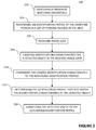
- FIG 3 an alternative method for tracking a person is displayed. This method is based on the method described with reference to figure 2 and have some of the steps in common with that method, the common steps are denoted with the same reference numbers for simplicity.
- the tracking method of figure 3 starts with identifying a person by matching credentials, step 202, and registering an identification profile of the identified person in a list of persons tracked in the area 405, step 204. Both step 202 and step 204 have been discussed earlier with reference to figure 2 .
- the identification profile is however also registered in a list of persons that has entered the area 505, step 304.
- the list of persons that has entered the area 505 comprises identification profiles of all persons that has been identified as entered the area. To keep the list accurate, persons that are identified as leaving the area may be removed from the list. Similar to the tracking method displayed in figure 2 image data is received in step 206 and identification characteristics for a detected object in the received image data is created in step 208.
- step 310 the created identification characteristics are then compared to the identification profiles in the list of persons tracked in the area 405 by calculating confidence scores of the correlation between the created identification characteristics and the corresponding identification characteristics of the identification profiles. Confidence scores have been discussed earlier and that discussion also applies to the confidence scores calculated in step 310.
- the identification profile that has the highest correlation with the created identification characteristics of the detected object and thereby generates the highest confidence scores is selected in step 213.
- the confidence score associated highest correlation is compared with a threshold in step 316. If the confidence score is larger than this threshold the match between the created identification characteristics and the identification profile has a good enough quality to continue to step 214 where the detected object is connected to the identification profile.
- the created identification characteristics are then compared to the identification profiles in the list of persons that has entered the area 505 by calculating confidence scores of the correlation between the created identification characteristics and the corresponding identification characteristics of the identification profiles, see step 318. Similar to step 312, the identification profile corresponding to the highest correlation is then selected in step 320 and connected to the detected object in step 214. If the calculated confidence score corresponding to the identification profile with the highest correlation to the set of identification characteristics of the detected object is smaller than a second predetermined threshold the act of connecting the detected object to the identification profile that generates the best match may not be performed. This will prevent the system from storing results that may be misleading. An alert may also be generated and transmitted to an operator of the system in such cases. It may be critical that these cases of matches with poor correlation are highlighted as a poor match as it may be an indication that a person not being permitted to access to the defined area 101 has gained access to the defined area 101 anyway.
- the list of persons tracked in the area 405 comprises a subset of the list of persons that has entered the area 505.
- the list of persons tracked in the area 405 are hence a list of persons that has entered the area and that are also presently being tracked or at least was connected to a detected object in recent time. This may be realized by using the earlier mentioned predetermined activity time period to remove identification profiles from the list of person tracked in the area which have not been connected to a detected object for a specific time period.
- the list of persons tracked in the area 405 will hence comprise the most likely candidates for a match with high correlation when an object is detected in image data.
- a second comparison step 318 will offer the possibility to also compare the identification characteristics with the identification profiles of persons that has entered the area but has not been connected to a detected object in recent time.
- the identification profile of that person may be removed from the list of persons that are tracked in the area 405 but as the person still will be on the list of persons that entered the area 505 the identification profile of that person may be selected when the person left the unmonitored room and was detected by a monitoring camera.
- the identification profile could also be registered on the list of persons tracked in the area 405 again in response to the step 214 of connecting a detected object to the identification profile in question.
- confidence scores may not need to be recalculated for the identification profiles in the list of persons tracked in the area 405 in step 318.
- the confidence scores calculated for these identification profiles in step 310 may be reused in step 318 or it may be decided that these identification profiles are not included in the comparison performed in step 318.
- Identification profiles of persons that have entered the area may also be removed from that list if a predetermined presence time period has passed since the point in time when the person was identified to enter the area. This would be useful in keeping the list of persons that have entered the area 505 up to date and accurate as there may be a possibility for persons to leave the defined area without being identified as leaving the area.
- the predetermined presence time period would typically be set to a time period that is longer than the expected presence time within the defined area. For example, if the defined area was an office complex this time period could set to the expected working time with some safety margin.
- the selected identification profile may be updated with the data from the created identification characteristics of the detected object.
- the updating of the identification profile may only be made if the correlation of the match is high enough, by for example comparing the confidence score to a predetermined threshold for updating.
- One way of performing the update may be to calculate a statistical measure based on the present information in the identification profile and information from the created set of identification characteristics.
- the system 400 for tracking a person comprises an identification module 402 arranged to identify a person entering a defined area by matching credentials presented by the person to credentials in an database including credentials of preregistered persons, a registration module 404 arranged to register an identification profile of a person in a list of persons that are tracked in the area 405, the identification profile comprising information for identifying the person, an image acquisition device 406 arranged to acquire image data from a scene within the area, an identification characteristics creation module 408 arranged to create a set of identification characteristics for an object detected in image data acquired by the image acquisition device, a matching module 410 arranged to compare a created set of identification characteristics of a detected object to the registered identification profiles in the list of persons that are tracked in the area 405 and determine the identification profile in the list of persons that are tracked in the area 405 that best match the set of identification characteristics of the detected object, and a tracking module 412 arranged to connect the detected object to the determined identification profile that best match the identification profile
- the identification module 402 of figure 4 may be implemented on a physical access controller 103a, 103b or on a server connected to the physical access control system, such as server 109a.
- a central server such as the 109a or 109b will typically include the functionality of the registration module 404, however the functionality of the registration module could alternatively be distributed on the monitoring cameras 107 or the physical access controllers 103 using peer to peer protocols known in the art.
- the registration module 404 could also, as yet another alternative, be implemented on local computation unit(s) serving one or more nearby monitoring camera(s) 107.
- the identification module 402 is connected to the registration module 404 and transmits an identifier of the identified person to the registration module 404 so that the identification profile of the identified person can be registered in the list of persons tracked in the area 405.
- the registration module 404 stores and handles the communication with regards to the entries of the list of persons tracked in the area 405 in connection to the other modules of system 400 and 500.
- the registration module 404 may comprise submodules, e.g. one submodule handling the communication with the other modules of the system 400 and 500, and one submodule storing the actual list of persons tracked in the area 405.
- Monitoring cameras 107 are examples of an image acquisition device 406 capturing image data from a scene within the defined area 101.
- the monitoring cameras 107 may also include the identification characteristics creation module or alternatively this module may be located on a central server 109b connected to the monitoring cameras 107.
- the monitoring cameras will in the latter case transmit image data of the monitored scene or specifically, if object detection is performed at the camera, image data of the detected object, to the central server 109b.
- the matching module 410 receives information about the registered identification profiles from the registration module 404 and the created identification characteristics from the identification characteristics creation module 408 in order to make a comparison to find the best match. As what has earlier been described this comparison may be made by calculating and comparing confidence scores. Data identifying the identification profile resulting in the best match will then be transmitted to the tracking module 412 which connects the detected object with this identification profile.
- the matching module 410 and the tracking module 412 may be implemented on a central server 109, a local computation unit(s) serving the nearby cameras, as distributed functionality on a plurality of monitoring cameras 107 or on physical access control servers 103.
- Figure 5 shows another example of a system 500 for tracking a person.
- the entrance registration module 514 registering identification profiles on a list of persons that have entered the area 505 of system 500 can be implemented as part of the physical access control system, e.g. included in a physical access controller 103 or on a central server connected to physical access controllers 103.
- the entrance registration module 514 stores information, and handles the communication, with regards to the entries of the list of persons that have entered the area 505 in connection to the other modules of system 500.
- the entrance registration module 514 may comprise submodules, e.g. one submodule handling the communication with the other modules of the system 500, and one submodule storing the actual list of persons that have entered the area 505.
- a second matching module 512 is included in system 500, matching identification profiles on the list of persons that has entered the area 505.
- the matching module 512 hence receives information about the registered identification profiles from the entrance registration module 514 and the created identification characteristics from the identification characteristics creation module 408 in order to make a comparison to find the best match.
- a deregistration module 516 is connected to the registration module 404 in system 500.
- the deregistration module 516 is arranged to deregister the identification profile of a person from the list of persons tracked in the area 405 if a predetermined activity time period has passed since the last point in time a detected object was connected to the identification profile and is hence connected to the registration module 404.
- the deregistration module 516 may be implemented on a central server, such as the 109a or 109b.
- the functionality of the deregistration module 516 could alternatively be distributed on the monitoring cameras 107 or on the physical access controllers 103 using peer to peer protocols known in the art.
- Another alternative is to implement the deregistration module 516 on local computation unit(s) serving one or more nearby monitoring camera(s) 107.
- the present invention may take the form of a non-transitory computer program product embodied in one or more computer readable medium(s) having computer readable program code embodied thereon.
- the physical access control system and monitoring system according to the invention may be further connected to a video management system, a so called VMS.
- a video management system manages monitoring cameras and video generated by the monitoring cameras but could also be extended to further manage a physical access control system.
- An operator interfacing with the VMS could hence also configure the system for tracking an object according to the invention.
- the mentioned thresholds for confidence scores could for example be configured by the operator using the VMS interface.
- the presence and activity time periods could similarly be configured using the VMS.
- connections made between the detected objects and the identification profiles could also be used by the VMS to gather for example image data and physical coordinates of an object specified by the operator. From the gathered image data and physical coordinates visual illustrations as well as statistics may be extracted for the use of the operator. This type of object tracking searches could be performed both using recorded material in a so called forensic video search as well as using live data.
Landscapes
- Engineering & Computer Science (AREA)
- Physics & Mathematics (AREA)
- Theoretical Computer Science (AREA)
- General Physics & Mathematics (AREA)
- Multimedia (AREA)
- Computer Vision & Pattern Recognition (AREA)
- Data Mining & Analysis (AREA)
- Health & Medical Sciences (AREA)
- Library & Information Science (AREA)
- General Engineering & Computer Science (AREA)
- Human Computer Interaction (AREA)
- Oral & Maxillofacial Surgery (AREA)
- General Health & Medical Sciences (AREA)
- Databases & Information Systems (AREA)
- Evolutionary Biology (AREA)
- Bioinformatics & Computational Biology (AREA)
- Bioinformatics & Cheminformatics (AREA)
- Life Sciences & Earth Sciences (AREA)
- Evolutionary Computation (AREA)
- Artificial Intelligence (AREA)
- Emergency Management (AREA)
- Signal Processing (AREA)
- Business, Economics & Management (AREA)
- Social Psychology (AREA)
- Geometry (AREA)
- Psychiatry (AREA)
- Software Systems (AREA)
- Image Analysis (AREA)
- Alarm Systems (AREA)
- Closed-Circuit Television Systems (AREA)
- Collating Specific Patterns (AREA)
Abstract
Description
- The present invention relates to the field of monitoring. In particular it relates to a method and system for tracking an object in a defined area monitored by cameras.
- Systems for object tracking have interesting applications within the field of camera monitoring. In many monitoring systems it is desired to be able to track objects, or more particularly persons, both in live video material and in recorded video material for forensic video searches.
- Object tracking systems aid in various safety related situations where a person's activities needs to be investigated in connection to e.g. criminal activities. The object tracking systems could however also be useful for non-security related applications such as collecting statistics for surveys. Many object tracking systems are applied to camera systems monitoring a defined area such as an office complex, a factory, a hotel, a gated community, a campus, or a premises where persons preregister to get access credentials.
- In order to track an object in a system of monitoring cameras (which may or may not have overlapping views) it is essential to be able to recognize the object, or at least a feature of the object, in image data from the different monitoring cameras. As the different monitoring cameras may have different optical configurations comprising different lenses, apertures, image sensors etc. and different image processing settings this might influence the appearance of objects in image data from the different cameras in the system. Further, the cameras may be mounted at different physical locations e.g. having different illumination schemes which also affects the appearance of objects in the image data acquired and processed by the cameras. These problems are discussed in
US 7,529,411 B2 . -
US 7,529,411 B2 teaches a system for recognition analysis of multiple streams of video where identifying information extracted from images captured by the video surveillance system are compared to one or more stored profiles. In a preferred embodiment of the system disclosed inUS 7,529,411 B2 the comparison is made with each stored profile, although it is possible that comparisons will only be made with a selected subset of the stored profiles. - A problem with the system discussed in
US 7,529,411 B2 is however that the recognition analysis will require a lot of processing power and processing time. - In view of the above, it is thus an object of the present invention to provide an improved method and system for tracking objects in a defined area. In particular, it is an object to provide a method and a system which decreases the processing time and performance needed to track an object in a defined area.
- According to a first aspect of the invention, the above object is achieved by a method for tracking a person. The method for tracking a person comprising the steps of: identifying a person entering a defined area by matching credentials presented by the person to credentials in a database including credentials of preregistered persons, registering an identification profile of the identified person in a list of persons that are tracked in the area, the identification profile comprising information for identifying the person from image data, receiving image data from a scene within the area, creating a set of identification characteristics for an object detected in the received image data, comparing the created set of identification characteristics of the detected object to the registered identification profiles in the list of persons that are tracked in the area, determining the identification profile in the list of persons that are tracked in the area that best match the set of identification characteristics of the detected object, and connecting the detected object to the determined identification profile that best match the identification profile of the detected object. An advantage of the method for tracking a person is that the processing time needed to track an object in a defined area is reduced and the reliability of correctly identifying a person from image data is increased as the identification characteristics of an object detected in image data are compared to the identification profiles of the persons presently tracked in the area. One reason for the reduced processing time is that fewer identification profiles need to be compared to the identification characteristics of the detected object. The increase in reliability is a result of that the likelihood of the identification characteristics being similarly matched to a plurality of identification profiles is decreased. An effect of this is also that with fewer identification profiles to compare with the reliability of the matching will increase as the probability of having candidates with similar features is decreasing, i.e. you may say that it probably will be easier for the process to correctly identify the person in the image due to greater difference between the identification profiles in the reduced list of persons to compare with as a result of the list includes fewer entries. This way the matching, and hence one of the most processing demanding steps of a tracking method, will be focused on the most likely candidates and not necessarily all theoretically possible candidates. It is a further advantage that the identification profile of the persons that have been identified as entering the defined area is registered on the list of persons tracked in the area and that the identification profile is connected to the credentials used for identification when entering the area. This way the reliability of the physical access system is increasing the possibilities of achieving a high reliability in the registration of the identification profiles on the list of persons tracked in the area. The registration of an identification profile is performed in connection to the person entering the defined area which gives the advantage of having the list of tracked persons assembled before an object, which might correspond to the person entering the area, is detected in received images. This will reduce the processing time and performance needed for each detected object in received images.
- In further embodiments of the invention the step of comparing the created set of identification characteristics to the registered identification profiles is performed by calculating confidence scores based on the correlation between the created identification profile and the registered identification profiles, and the step of determining the identification profile that best match the created set of identification characteristics is performed by selecting the identification profile corresponding to the confidence score representing the highest correlation with the created set of identification characteristics. An advantage with using confidence scores to determine the highest correlation is that it quantifies the correlation in a processing efficient way.
- In yet further embodiments of the invention the act of connecting is not performed if the calculated confidence score corresponding to the identification profile with the highest correlation to the set of identification characteristics of the detected object is smaller than a first predetermined threshold. This makes it possible to sort out the cases where a poor correlation is the best correlation and preventing the poor correlation from affecting the tracking.
- In other embodiments this is further developed generating an alert if the calculated confidence score corresponding to the identification profile with the highest correlation to the set of identification characteristics of the detected object is smaller than the first predetermined threshold. As the poor match may be due to a detected intruder, that has entered the defined area without proper identification using valid credentials and hence is not part of the list of persons tracked in the area, generating an alert will improve the security of the defined area.
- In further embodiments additional steps of identifying a person leaving the defined area by matching credentials presented by the person to credentials in a database including credentials of preregistered persons, and removing the identification profile of the identified person leaving the defined area from the list of persons that are tracked in the area are introduced. These embodiments will add to keeping the list of persons tracked in the area updated and removing persons leaving the defined area will reduce the list of candidates and hence reduce the processing time and at the same time increase the reliability of the tracking.
- In yet further embodiments the identification profile of a person is removed from the list of persons tracked in the area if a predetermined activity time period has passed since the last point in time a detected object was connected to the identification profile. These embodiments alternatively or in combination with what has previously been described add to keeping the list of persons tracked in the area updated. These embodiments will reduce the list of candidates and hence reduce the processing time.
- In further embodiments a step of registering the identification profile of the identified person in a list of persons that have entered the area is added to the method. The addition of another list including persons that have entered the area is advantageous in that the processing time and resources may be reduced in the majority of cases when the tracking method is used, as only the most likely candidates are on the list of persons tracked in the area, but in the rare cases that one of the most likely candidates does not generate a match with good enough correlation the list of persons that has entered the area will offer the possibility to also compare the identification characteristics with the identification profiles of persons that has entered the area but has not been connected to a detected object in recent time.
- This is further developed in yet other embodiments of the invention wherein if the calculated confidence score corresponding to the identification profile with the highest correlation to the set of identification characteristics of the detected object in the received image data is smaller than a second predetermined threshold, the act of connecting is not performed,
and the method is further comprising, comparing the created set of identification characteristics of the detected object in the received image data to the registered identification profiles in the list of persons that have entered the area, determining the identification profile in the list of persons that have entered the area that best match the set of identification characteristics of the detected object in the received image data, and connecting the detected object in the received image data to the determined identification profile that best match the set of identification characteristics of the detected object in the received image data. - This offers the possibility of matching candidates in a list of persons that has entered the area if the confidence score of the match with the highest correlation is not good enough with a candidate from the list of persons tracked in the area. This further adds to the reliability of the system.
- In further embodiments the comparison of the created set of identification characteristics of the detected object in the received image data to the registered identification profiles in list of persons that have entered the area is performed by calculating confidence scores based on the correlation between the created set of identification characteristics of the detected object in the received image data and the identification profile of the persons in the list of persons that have entered the area, and the determination of the identification profile in the list of persons that have entered the area that best match the created set of identification characteristics is performed by selecting the identification profile corresponding to the confidence score representing the highest correlation with the created set of identification characteristics of the detected object in the received image data. An advantage with using confidence scores to determine the highest correlation is that it quantifies the correlation in a processing efficient way.
- In yet other embodiments of the invention the identification profile comprises one or more sets of identification characteristics for describing the appearance of a person, selected from the group consisting of: characteristic geometrical parameters of the body or the face of a person, mathematical expressions representing facial features or features of the body of a person, texture parameters of a person's clothing, skin or face, color spectrum from the image of a person or part of a person, gait of a person, a movement pattern of a person. The identification characteristics for describing the appearance of a person further adds to the processing efficiency and reliability of the method for tracking as it offers ways to calculate and process appearance features.
- In another embodiment the information in the identification profile that best match the set of identification characteristics of the detected object is updated with information from the created set of identification characteristics. This offers the advantage of continuously updating the identification characteristics, being important for the reliability of the tracking as the visual appearance of person may be easily modified in a short period of time. For example, clothing might change if a person takes off a coat, wears glasses or not, has shaved off the beard etc.
- In yet other embodiments the act of updating the information in the identification profile is performed by calculating a statistical measure based on the present information in the identification profile and information from the created set of identification characteristics. This further adds a processing efficient way of updating the identification profile.
- In yet further embodiments of the invention the step of connecting the detected object to the determined identification profile that best match the set of identification characteristics of the detected object further is comprising registering information related to the image data selected from the group of an identifier of the image acquisition device that acquired the image data, the point in time in which the image data was acquired by the image acquisition device and the position of the image acquisition device that acquired the image data. This adds the advantage of having additional information concerning the location, image acquisition device and/or point in time of the object detection, which improves the confidence of making the correct identification and hence the object tracking ability in the defined area.
- According to a second aspect of the invention relates to a computer program product comprising a computer-readable storage medium with instructions adapted to carry out the method described in connection to the first aspect of the invention when executed by a processor. Advantages corresponding to the first aspect of the invention are also applicable for this second aspect of the invention.
- According to a third aspect the present invention relates to a system for tracking a person, comprising; an identification module arranged to identify a person entering a defined area by matching credentials presented by the person to credentials in an database including credentials of preregistered persons, a registration module arranged to register an identification profile of a person in a list of persons that are tracked in the area, the identification profile comprising information for identifying the person, an image acquisition device arranged to acquire image data from a scene within the area, an identification characteristics creation module arranged to create a set of identification characteristics for an object detected in image data acquired by the image acquisition device, a matching module arranged to compare a created set of identification characteristics of a detected object to the registered identification profiles in the list of persons that are tracked in the area and determine the identification profile in the list of persons that are tracked in the area that best match the set of identification characteristics of the detected object, and a tracking module arranged to connect the detected object to the determined identification profile that best match the identification profile of the detected object. Advantages corresponding to the first aspect of the invention are also applicable for this third aspect of the invention.
- According to further embodiments of the third aspect the system is further comprising an entrance registration module arranged to register an identification profile of a person in a list of persons that have entered the area, the identification profile comprising information for identifying the person from image data, a deregistration module arranged to deregister the identification profile of a person from the list of persons tracked in the area if a predetermined activity time period has passed since the last point in time a detected object was connected to the identification profile, a matching module arranged to compare a created set of identification characteristics of a detected object in image data to the registered identification profiles in the list of persons tracked in the area and determine the identification profile in the list of persons tracked in the area that best match the set of identification characteristics of the detected object in image data.
- A further scope of applicability of the present invention will become apparent from the detailed description given below. However, it should be understood that the detailed description and specific examples, while indicating preferred embodiments of the invention, are given by way of illustration only, since various changes and modifications within the scope of the invention will become apparent to those skilled in the art from this detailed description. Hence, it is to be understood that this invention is not limited to the particular component parts of the device described or steps of the methods described as such device and method may vary. It is also to be understood that the terminology used herein is for purpose of describing particular embodiments only, and is not intended to be limiting. It must be noted that, as used in the specification and the appended claim, the articles "a", "an," "the", and "said" are intended to mean that there are one or more of the elements unless the context clearly dictates otherwise. Thus, for example, reference to "a sensor" or "the sensor" may include several sensors, and the like. Furthermore, the word "comprising" does not exclude other elements or steps.
- Other features and advantages of the present invention will become apparent from the following detailed description of a presently preferred embodiment, with reference to the accompanying drawings, in which
-
Fig. 1 illustrates an example of a definedarea 101. -
Fig. 2 is a block scheme of a method for tracking an object according to the invention. -
Fig. 3 is a block scheme of an alternative method for tracking an object according to the invention. -
Fig. 4 is a block diagram of a system for tracking an object according to the invention. -
Fig. 5 is a block diagram of an alternative system for tracking an object according to the invention. - Further, in the figures like reference characters designate like or corresponding parts throughout the several figures.
- A tracking method and system according to one embodiment of the present invention may be applied to a camera system monitoring a defined area such as an office complex, a factory, a hotel, a gated community, a campus, or a premises where persons preregister to get access credentials. In this detailed description a defined area is an area to which entrance is controlled by a physical access control system.
- There are different approaches for tracking an object known in the art, one of which is based on detecting a target object and matching features of the target object with features of stored candidate objects to find the best match are essential steps of a tracking method. The number of candidate objects to a defined area may be large. In the example of a defined area being a factory it is of course the people working in the factory, there may for example be different teams working in shift, persons delivering goods to the factory and transportation personnel for delivering products from the factory, temporary visitors, various service personnel, security personnel etc. In addition to the fact that the number of candidate objects in a defined area such in the example above is large, the number of concurrent target objects in the area may also be high, in particular during specific time periods. An example of where and when there are a larger number of concurrent objects is in a factory when one team of workers are finishing a shift and another team of workers is starting their shift. A tracking system connected to the cameras monitoring a defined area hence needs to be able to manage both a large number of candidate objects and a large number of concurrent target objects. The large number of candidate objects implying that a lot of processing will be needed for each detected target object and a large number of detected target objects meaning that this processing will be needed to be performed frequently.
- An example of a system according to one embodiment of the invention is depicted in
figure 1 . The definedarea 101 is accessed through entrance(s) 102a, 102b which are controlled byphysical access controllers physical access controllers area 101 to credentials in a database including credentials of preregistered persons. Such physical access control systems may be used at factories, offices, schools, laboratories, hotels etc. where access to certain areas are restricted to a specified group of persons that have been preregistered. The matching of the credentials as well as the storage of the credential database may be handled locally on theaccess controller server 109a connected to theaccess controllers figure 1 theserver 109a is placed in box with dashed lines outside, but connected to, the definedarea 101. The purpose of this representation of theserver 109a is to show that the server may be physically located within the definedarea 101 or outside the defined area, in case theserver 109a is located outside the definedarea 101 it would be connected to theaccess controllers access controllers credential input device physical access controllers area 101, e.g. via a door, an elevator, a gate, a turnstile, a sliding door, or another movable blocking device that may be put in a passage to prevent people from entering the definedarea 101 without presenting their credentials. Depending on the success of matching presented credentials with the credentials in the credential database, and various access rules, a person may be given access to the defined area. An access rule may for example regulate time periods during which access will be granted to preregistered persons. - An
entrance 102b may be located in connection to aregistration area 105 where a person about to request access to the definedarea 101 may preregister in order to get credentials for accessing the definedarea 101. - A
camera 106 may be used for capturing images of the person for the preregistration. The captured images may be used for compiling an identification profile comprising information for identifying the person from image data. The identification profile comprises one or more sets of identification characteristics for describing the appearance of a person. Examples of identification characteristics are characteristic geometrical parameters of the body or the face of a person, mathematical expressions representing facial features or features of the body of a person, texture parameters of a person's clothing, skin or face, colour spectrum from the image of a person or part of a person, gait of a person, a movement pattern of a person. In addition to identification characteristics for describing the appearance of a person the identification profile could also comprise other descriptors of the person, e.g. earlier determined positions of a person within the defined area, or identifiers transmitted from various mobile devices carried by the person. The compilation of an identification profile may or may not be a part of the preregistration process. Alternatively, the identification profile may be compiled using image data from cameras 107 a-f monitoring the definedarea 101, after the person has entered the definedarea 101. Image data used in the identification profile may also be collected partly during the preregistration and partly in a definedarea 101. Yet another alternative is to import identification profiles or data that could be used to compile an identification profile from another source, such as another monitoring system. - The identification profile may also be continuously updated with image data from cameras 107 a-f monitoring a defined
area 101. Continuously updating the identification profile may be useful as at least some of the data relating to the appearance of a person might change over time, like for example clothing, glasses, haircuts etc. - Preregistration may be performed in other locations than in the above discussed
registration area 105. The preregistration may for example be performed in other registration areas located remote from the definedarea 101. A designated registration area may not even be needed as long as the credentials to be used when requesting access to the defined area may be transmitted and inserted into the credential database of the physical access control system controlling access to the definedarea 101. - A second defined
area 108 may also be located inside the definedarea 101, so that a person first needs to request access to the definedarea 101 before entering the second definedarea 108. Access rules may be defined in the physical access control system so that all persons having access to the first part of the definedarea 101 may also access the second definedarea 108, access rules may alternatively be configured so that a subgroup of the persons that may enter the first part of the definedarea 101 also can enter the second definedarea 108. The second definedarea 108 is accessed throughentrance 102c which are controlled byphysical access controller 103c. Thephysical access controller 103c is part of the physical access control system adapted to control physical access to the defined area by matching credentials presented by a person requesting access to the defined area to credentials in a database including credentials of preregistered persons. The matching of the credentials as well as the storage of the credential database may be handled locally on theaccess controller 103c or at a server connected to the access controllers, as foraccess controllers 103a-b. Theaccess controller 103c is also connected to acredential input device 104c, similar to what has been previously explained for credential input devices 104 a-b. - A plurality of
monitoring cameras 107a-f are monitoring the definedarea 101. The monitoring cameras 107 a-f may monitor the entrances 102 a-b to the first part of the definedarea 101 as well as the entrances to a second definedarea 108 located inside definedarea 101 and also other areas within the defined areas. Themonitoring cameras 107a-f are connected to a monitoring system that may also include aserver 109b for storing, processing and managing image data. The monitoring system may also include local computational devices servingnearby monitoring cameras 107a-f. The devices connected to the monitoring system are communicating via a network, the network may be any kind of communication network, such as a wire line or wireless data communication network, e.g. a local area network (LAN) or a wireless local area network (W-LAN) or a Wide Area Network (WAN).Themonitoring cameras 107a-f may be any digital video cameras capable of generating image sequences and/or any analog video cameras capable of generating image sequences. In the case of a monitoring camera being an analog video camera the analog video camera is connected to a converter transforming the analog image information to digital image data and providing the digital image data to the network 20. Such a converter might be a video encoder or a video server. Infigure 1 theserver 109b is placed in box with dashed lines outside, but connected to, the definedarea 101. The purpose of this representation of theserver 109b is, as mentioned previously, to show that the server may be physically located within the definedarea 101 or outside the defined area, in case theserver 109b is located outside the definedarea 101 it would be connected to themonitoring cameras 107a-f through the network. Alternatively the monitoring cameras 107 a-f may be equipped to handle storage, processing and management of image data locally or by using a local computational device serving nearby monitoring cameras 107 a-f. The monitoring system handles the stored identification profiles and manages object tracking of objects in image data acquired by the monitoring cameras. The monitoring system is connected to the physical access control system. Theservers figure 1 drawn as separate units but the functionality ofserver - Now referring to
figure 2 , a method for tracking a person in a definedarea 101, such as the one depicted infigure 1 , is described. The method starts by identifying a person entering a defined area,step 202. The identification is performed by matching credentials presented to the system by the person to credentials in a database including credentials of preregistered persons. Step 202 may be performed by the physical access control system described in connection tofigure 1 , for example comprising a credential input device 104 for reading the credential presented by the person and an access controller 103 matching the presented credentials to credentials in a database including credentials of preregistered persons. The access controller 103 could however as an alternative transmit the presented credentials to acentral server 109a, performing the matching of the presented credentials with credentials of preregistered persons. - After the
step 202, of identifying a person entering the definedarea 101, an identification profile of the identified person is registered in a list of persons that are tracked in the area 405 (step 204). There are various alternatives for performingstep 204, if an identification profile for the identified person is available for the monitoring system the identification profile may be labelled as "tracked" or similar. A pointer to the identification profile in question may alternatively be generated from a list of persons that are tracked in thearea 405, of course the identification profile may also by copied to designated memory for the list of persons that are tracked in thearea 405. If an identification profile of the identified person is not available for the monitoring system a new identification profile may be generated from image data captured by monitoring cameras 107 monitoring the definedarea 101. As an example amonitoring camera 107c monitoring theentrance 102a to the definedarea 101 may be used to capture image data from which identification characteristics for describing the appearance of the identified person may be extracted and registered in an identification profile. Image data captured by monitoringcameras 107c monitoring theentrance 102a to the definedarea 101 may also be useful for updating available identification profiles with identification characteristics describing the current appearance of the identified person. The advantage of using image data captured by amonitoring camera 107c monitoring theentrance 102a to the definedarea 101 for updating the identification profile is that it is performed when, or shortly after, the person has been identified by presenting and matching credentials, implying that a positive identification of the person has been made with enough confidence to let the person in to the defined area. If the person for example has a new haircut, new pair of glasses, or simply a new outfit changing the appearance of the person the identification profile may be adapted for this at a point in the system where the identification of the person is known from the presented credentials. - The tracking method then continues with receiving image data (step 206) from a scene within the area. The received image data is captured by any of the monitoring cameras 107 monitoring the defined
area 101. An object may be detected in the received image data by any object detection algorithm known in the art. Moving objects may for example be detected by means of motion detection algorithms. Some examples of motion detection algorithms are change detection algorithms comparing video frames and detecting changes between the video frames, algorithms using background models of the monitored scene to extract moving foreground objects, spatiotemporal algorithms such as described inUS 8,121,424 by Almbladh or any combination of these. An example of an alternative to detecting objects by their motion is to detect the objects by their visual features, using shape detection. There are various types of such object detection methods known in the art where cascades of identifiers are used to detect objects, e.g. as described in Viola, Paul, and Michael Jones. "Rapid object detection using a boosted cascade of simple features." Computer Vision and Pattern Recognition, 2001. CVPR 2001. Proceedings of the 2001 IEEE Computer Society Conference on. Vol. 1. IEEE, 2001. Since it is the visual features that are important for these algorithms groups of objects that share similar visual features may be detected, examples of such groups are faces, vehicles, humans etc. Any of these methods may be used separately or in combination to detect an object in image data. Several objects may also be detected in the same set of image data. The object detection may be performed at the monitoring cameras 107, either by the monitoring camera that captured the image data or another monitoring camera that received the imaged data from a monitoring camera that captured the image data. Alternatively, the object detection may be performed at aserver 109b connected to the monitoring cameras 107 in the monitoring system or at a local computational device serving nearby monitoring cameras 107. - When an object has been detected in the image data a set of identification characteristics is created to describe the visual appearance of the detected object,
step 208. Image data from a single image frame or a video sequence captured by one or more monitoring cameras 107 monitoring the definedarea 101 may be used to create the identification characteristics for the detected object. Various image and/or video analysis algorithms may be used to extract and create the identification characteristics from the image data. Examples of such image or video analysis algorithms are various algorithms e.g. for extracting features in a face such in Turk, Matthew A., and Alex P. Pentland. "Face recognition using eigenfaces." Computer Vision and Pattern Recognition, 1991. Proceedings CVPR'91., IEEE Computer Society Conference on. IEEE, 1991., gait features such in Lee, Lily, and W. Eric L. Grimson. "Gait analysis for recognition and classification." Automatic Face and Gesture Recognition, 2002. Proceedings. Fifth IEEE International Conference on. IEEE, 2002., or colors such inUS 8,472,714 by Brogren et al. - The identification characteristics may be created at the monitoring camera that captured the image data, another monitoring camera in the monitoring system, at a local computational unit serving nearby cameras or at a
server 109b connected to the monitoring cameras. The creation of the identification characteristics is made in response to an object being detected in the received image data. If the object is detected in one part of the system and the creation of the identification characteristics is to be performed in another part of the system, data describing the detected object in the image data may be transmitted from the part detecting the object to the part that is to create identification characteristics. Examples of such data describing the detected component in the image data may be image coordinates, time stamp, object label, colour identifiers, image of the object etc. This will enable the receiving part to continue the method of tracking the object with creating identification characteristics of the detected object. - The created identification characteristics are then stored for the detected object and compared to the identification characteristics in the registered identification profiles in the list of persons that are tracked in the area 405 (step 210). By keeping a list of persons that are tracked in the
area 405 there is no need to compare the created identification characteristics of the detected person to the complete list of persons that have the possibility to be in the defined area, e.g. all employees at a manufacturing facility, all persons working at an office, all persons living at a gated community etc. This results in that the accuracy in of the identification is improved, that a lot of processing power and processing time is saved and that the actual processing may be performed at a component of the system with limited processing power and time. Due to the fact that the persons on the list of persons that are tracked in thearea 405 are registered and there by entered to the list in response to entering the defined area no time or processing power is needed to assemble the list as a part ofstep 210 where the comparison is made. It is likely to assume that thecomparison step 210 is made more frequently by the system than the identification andregistration steps area 101 are likely to move around the definedarea 101 and may be detected in image data captured by monitoring cameras 107 at many locations within the defined area. The processing associated with assembling the list will hence also be reduced by registering the identified persons entering the definedarea 101 in response to identification,step 202. - In
step 212 the identification profile in the list of persons that are tracked in thearea 405 that best match the set of identification characteristics of the detected object is determined. This may be performed by calculating confidences scores describing how well the identification characteristics in the identification profile match the created identification characteristics of the detected object. The confidence score may for example be defined as a percentage where 100%, or 1, denotes an identical match of identification characteristics and 0%, or 0, denotes two completely different identification characteristics. The matching of identification characteristics may be difficult to perform as the image data being used as a basis for the match is susceptible to lighting conditions, image processing artifacts, performance of the monitoring cameras etc. In order to increase the reliability of the match several different identification characteristics may be used in parallel and a combined result may be used. A neural network approach may be used to determine the identification profile that best match the created identification characteristics of the detected object. A neural network would then be trained to find the best match with the highest correlation between identification profiles and identification characteristics of a detected object, and be implemented on aserver 109a-b or distributed over the monitoring cameras 107 or over local computational units connected to the monitoring cameras. Based on the experiences of the training, the neural network would then use the combination of identification characteristic(s) that would be most efficient in reaching the best match. Some identification characteristics may hence not be used in such a scenario, if they would not be efficient in finding the best match. The efficiency in finding a match may for example refer to the success of actually finding the best match, the resources needed to find the best match, the time it would take to find the best match or the processing power needed to find the best match. A neural network may be implemented to use one, or a combination, of possible approaches for performing the matching. There are different matching approaches known in the art, e.g. the Euclidean distance between the identification characteristics of a detected object and the identification characteristics of an identification profile may be used in the matching as by Schroff et al in "Facenet: A unified embedding for face recognition and clustering." Proceedings of the IEEE Conference on Computer Vision and Pattern Recognition. 2015. An alternative is to apply algorithms based on feature cascades such as the one disclosed by Viola and Jones in "Rapid object detection using a boosted cascade of simple features." Computer Vision and Pattern Recognition, 2001. CVPR 2001. Proceedings of the 2001 IEEE Computer Society Conference on. Vol. 1. IEEE, 2001. In the case of using the Euclidean distance approach a short Euclidean distance would represent a high correlation while a large Euclidean distance would represent a low correlation between the identification characteristics. - In
step 214 the detected object is connected to the determined identification profile that best match the identification profile of the detected object. The connection may be implemented as reference, tag or pointer saved as metadata connected to the image frame in which the object was detected. Alternatively, or in combination a reference, tag or pointer to the video frame or sequence of video frames or alternatively the point in time, or time interval, and location of the scene or camera which captured the images of the detected object may be stored in the identification profile that was determined to best match the identification characteristics of the detected object. - In addition to using the confidence scores for finding the best match of the identification characteristics they may also be used as indication of that the best match is in fact a poor match. If the calculated confidence score corresponding to the identification profile with the highest correlation to the set of identification characteristics of the detected object is smaller than a first predetermined threshold the act of connecting the detected object to the identification profile that generates the best match may not be performed. This will prevent the system from storing results that may be misleading. An alert may also be generated and transmitted to an operator of the system in such cases. It may be critical that these cases of matches with poor correlation are highlighted as a poor match as it may be an indication that a person not being permitted to access to the defined
area 101 has gained access to the definedarea 101 anyway. - In order to keep the list of persons that are tracked in the
area 405 up to date and accurate persons that are identified as leaving the definedarea 101 may be removed from this list. Persons may be identified as leaving the definedarea 101 by presenting credentials in order to open e.g. a door enabling them to leave the definedarea 101. The presented credentials can then be matched to the credentials in a database including credentials of preregistered persons to find their identity, and removing their identification profile from the list of persons that are tracked in thearea 405. - Identification profiles that has not been connected to a detected object during a predetermined activity time period may also be removed from the list of persons that are tracked in the
area 405. So if a person that has entered the definedarea 101 stays at a location with no monitoring within the definedarea 101 or leaves the definedarea 101 without being identified as leaving the definedarea 101, that person would be removed from the list of persons that are tracked in thearea 405 after the predetermined activity time period has passed since the identification profile of the person was last connected to a detected object. This feature may be implemented to keep the list of persons that are tracked in thearea 405 accurate and not including more persons than necessary, to reduce the processing time of the tracking and increase the identification accuracy. The range of the predetermined activity time period may vary from system to system. In a definedarea 101 where a lot of people are moving around frequently and it is difficult to identify persons leaving the area it may be wise to set this time period to be quite short. In a system where only a few people are expected to move around and maybe stay at places not being monitored within the definedarea 101 for a longer period of time, like for example in a hotel, this predetermined activity time period would typically be set to a longer time period. - In
figure 3 , an alternative method for tracking a person is displayed. This method is based on the method described with reference tofigure 2 and have some of the steps in common with that method, the common steps are denoted with the same reference numbers for simplicity. - The tracking method of
figure 3 starts with identifying a person by matching credentials,step 202, and registering an identification profile of the identified person in a list of persons tracked in thearea 405,step 204. Bothstep 202 and step 204 have been discussed earlier with reference tofigure 2 . The identification profile is however also registered in a list of persons that has entered thearea 505,step 304. The list of persons that has entered thearea 505 comprises identification profiles of all persons that has been identified as entered the area. To keep the list accurate, persons that are identified as leaving the area may be removed from the list. Similar to the tracking method displayed infigure 2 image data is received instep 206 and identification characteristics for a detected object in the received image data is created instep 208. Instep 310 the created identification characteristics are then compared to the identification profiles in the list of persons tracked in thearea 405 by calculating confidence scores of the correlation between the created identification characteristics and the corresponding identification characteristics of the identification profiles. Confidence scores have been discussed earlier and that discussion also applies to the confidence scores calculated instep 310. The identification profile that has the highest correlation with the created identification characteristics of the detected object and thereby generates the highest confidence scores is selected in step 213. In order to examine the quality of the match between the created identification characteristics and the identification profile with the highest correlation the confidence score associated highest correlation is compared with a threshold instep 316. If the confidence score is larger than this threshold the match between the created identification characteristics and the identification profile has a good enough quality to continue to step 214 where the detected object is connected to the identification profile. - But if the confidence score is not larger than the threshold, this indicates that the match between the created identification characteristics and the identification profile has poor correlation. This could typically be the case when a person that has been removed from the list of persons that are tracked in the
area 405 has started to move in the monitored part of the area again. Poor correlation could also indicate that a person has entered the area without presenting credentials. - The created identification characteristics are then compared to the identification profiles in the list of persons that has entered the
area 505 by calculating confidence scores of the correlation between the created identification characteristics and the corresponding identification characteristics of the identification profiles, seestep 318. Similar to step 312, the identification profile corresponding to the highest correlation is then selected instep 320 and connected to the detected object instep 214. If the calculated confidence score corresponding to the identification profile with the highest correlation to the set of identification characteristics of the detected object is smaller than a second predetermined threshold the act of connecting the detected object to the identification profile that generates the best match may not be performed. This will prevent the system from storing results that may be misleading. An alert may also be generated and transmitted to an operator of the system in such cases. It may be critical that these cases of matches with poor correlation are highlighted as a poor match as it may be an indication that a person not being permitted to access to the definedarea 101 has gained access to the definedarea 101 anyway. - The list of persons tracked in the
area 405 comprises a subset of the list of persons that has entered thearea 505. The list of persons tracked in thearea 405 are hence a list of persons that has entered the area and that are also presently being tracked or at least was connected to a detected object in recent time. This may be realized by using the earlier mentioned predetermined activity time period to remove identification profiles from the list of person tracked in the area which have not been connected to a detected object for a specific time period. The list of persons tracked in thearea 405 will hence comprise the most likely candidates for a match with high correlation when an object is detected in image data. Processing time and resources will hence be reduced in the majority of cases when the tracking method is used as only the most likely candidates are used in thecomparison step 310 and in the rare cases that one of the most likely candidates does not generate a match with good enough correlation asecond comparison step 318 will offer the possibility to also compare the identification characteristics with the identification profiles of persons that has entered the area but has not been connected to a detected object in recent time. So if a person enters a definedarea 101 but then for example stays in a room not monitored by any of the monitoring cameras 107 for a time period longer than the predetermined activity time period the identification profile of that person may be removed from the list of persons that are tracked in thearea 405 but as the person still will be on the list of persons that entered thearea 505 the identification profile of that person may be selected when the person left the unmonitored room and was detected by a monitoring camera. - In such a case when an identification profile has been removed from the list of persons tracked in the
area 405 the identification profile could also be registered on the list of persons tracked in thearea 405 again in response to thestep 214 of connecting a detected object to the identification profile in question. - Due to the fact that the list of persons tracked in the
area 405 comprises a subset of the list of persons that has entered thearea 505, confidence scores may not need to be recalculated for the identification profiles in the list of persons tracked in thearea 405 instep 318. The confidence scores calculated for these identification profiles instep 310 may be reused instep 318 or it may be decided that these identification profiles are not included in the comparison performed instep 318. - Identification profiles of persons that have entered the area may also be removed from that list if a predetermined presence time period has passed since the point in time when the person was identified to enter the area. This would be useful in keeping the list of persons that have entered the
area 505 up to date and accurate as there may be a possibility for persons to leave the defined area without being identified as leaving the area. The predetermined presence time period would typically be set to a time period that is longer than the expected presence time within the defined area. For example, if the defined area was an office complex this time period could set to the expected working time with some safety margin. - In response to step 214 of connecting the detected object to the selected identification profile the selected identification profile may be updated with the data from the created identification characteristics of the detected object. As an alternative the updating of the identification profile may only be made if the correlation of the match is high enough, by for example comparing the confidence score to a predetermined threshold for updating. One way of performing the update may be to calculate a statistical measure based on the present information in the identification profile and information from the created set of identification characteristics.
- In connection to
figure 4 asystem 400 for tracking a person will be discussed. Thesystem 400 for tracking a person comprises anidentification module 402 arranged to identify a person entering a defined area by matching credentials presented by the person to credentials in an database including credentials of preregistered persons, aregistration module 404 arranged to register an identification profile of a person in a list of persons that are tracked in thearea 405, the identification profile comprising information for identifying the person, animage acquisition device 406 arranged to acquire image data from a scene within the area, an identificationcharacteristics creation module 408 arranged to create a set of identification characteristics for an object detected in image data acquired by the image acquisition device, amatching module 410 arranged to compare a created set of identification characteristics of a detected object to the registered identification profiles in the list of persons that are tracked in thearea 405 and determine the identification profile in the list of persons that are tracked in thearea 405 that best match the set of identification characteristics of the detected object, and atracking module 412 arranged to connect the detected object to the determined identification profile that best match the identification profile of the detected object. - The
identification module 402 offigure 4 may be implemented on aphysical access controller server 109a. A central server, such as the 109a or 109b will typically include the functionality of theregistration module 404, however the functionality of the registration module could alternatively be distributed on the monitoring cameras 107 or the physical access controllers 103 using peer to peer protocols known in the art. Theregistration module 404 could also, as yet another alternative, be implemented on local computation unit(s) serving one or more nearby monitoring camera(s) 107. Theidentification module 402 is connected to theregistration module 404 and transmits an identifier of the identified person to theregistration module 404 so that the identification profile of the identified person can be registered in the list of persons tracked in thearea 405. Theregistration module 404 stores and handles the communication with regards to the entries of the list of persons tracked in thearea 405 in connection to the other modules ofsystem registration module 404 may comprise submodules, e.g. one submodule handling the communication with the other modules of thesystem area 405. - Monitoring cameras 107 are examples of an
image acquisition device 406 capturing image data from a scene within the definedarea 101. The monitoring cameras 107 may also include the identification characteristics creation module or alternatively this module may be located on acentral server 109b connected to the monitoring cameras 107. The monitoring cameras will in the latter case transmit image data of the monitored scene or specifically, if object detection is performed at the camera, image data of the detected object, to thecentral server 109b. - The
matching module 410 receives information about the registered identification profiles from theregistration module 404 and the created identification characteristics from the identificationcharacteristics creation module 408 in order to make a comparison to find the best match. As what has earlier been described this comparison may be made by calculating and comparing confidence scores. Data identifying the identification profile resulting in the best match will then be transmitted to thetracking module 412 which connects the detected object with this identification profile. Thematching module 410 and thetracking module 412 may be implemented on a central server 109, a local computation unit(s) serving the nearby cameras, as distributed functionality on a plurality of monitoring cameras 107 or on physical access control servers 103. -
Figure 5 shows another example of asystem 500 for tracking a person. Some of the modules discussed earlier, in connection tosystem 400, are present insystem 500. The description of those modules also apply tosystem 500. - The
entrance registration module 514 registering identification profiles on a list of persons that have entered thearea 505 ofsystem 500 can be implemented as part of the physical access control system, e.g. included in a physical access controller 103 or on a central server connected to physical access controllers 103. Theentrance registration module 514 stores information, and handles the communication, with regards to the entries of the list of persons that have entered thearea 505 in connection to the other modules ofsystem 500. Theentrance registration module 514 may comprise submodules, e.g. one submodule handling the communication with the other modules of thesystem 500, and one submodule storing the actual list of persons that have entered thearea 505. In addition to thematching module 410 working with the list of persons tracked in the area 405 asecond matching module 512 is included insystem 500, matching identification profiles on the list of persons that has entered thearea 505. Thematching module 512 hence receives information about the registered identification profiles from theentrance registration module 514 and the created identification characteristics from the identificationcharacteristics creation module 408 in order to make a comparison to find the best match. - A
deregistration module 516 is connected to theregistration module 404 insystem 500. Thederegistration module 516 is arranged to deregister the identification profile of a person from the list of persons tracked in thearea 405 if a predetermined activity time period has passed since the last point in time a detected object was connected to the identification profile and is hence connected to theregistration module 404. Similar to theregistration module 404 thederegistration module 516 may be implemented on a central server, such as the 109a or 109b. However, the functionality of thederegistration module 516 could alternatively be distributed on the monitoring cameras 107 or on the physical access controllers 103 using peer to peer protocols known in the art. Another alternative is to implement thederegistration module 516 on local computation unit(s) serving one or more nearby monitoring camera(s) 107. - Furthermore, the present invention may take the form of a non-transitory computer program product embodied in one or more computer readable medium(s) having computer readable program code embodied thereon.
- The physical access control system and monitoring system according to the invention may be further connected to a video management system, a so called VMS. In general a video management system manages monitoring cameras and video generated by the monitoring cameras but could also be extended to further manage a physical access control system. An operator interfacing with the VMS could hence also configure the system for tracking an object according to the invention. The mentioned thresholds for confidence scores could for example be configured by the operator using the VMS interface. The presence and activity time periods could similarly be configured using the VMS.
- The connections made between the detected objects and the identification profiles could also be used by the VMS to gather for example image data and physical coordinates of an object specified by the operator. From the gathered image data and physical coordinates visual illustrations as well as statistics may be extracted for the use of the operator. This type of object tracking searches could be performed both using recorded material in a so called forensic video search as well as using live data.
Claims (16)
- A method for tracking a person, comprising:identifying a person entering a defined area by matching credentials presented by the person to credentials in a database including credentials of preregistered persons,registering an identification profile of the identified person in a list of persons that are tracked in the area, the identification profile comprising information for identifying the person from image data,receiving image data from a scene within the area,creating a set of identification characteristics for an object detected in the received image data,comparing the created set of identification characteristics of the detected object to the registered identification profiles in the list of persons that are tracked in the area,determining the identification profile in the list of persons that are tracked in the area that best match the set of identification characteristics of the detected object, andconnecting the detected object to the determined identification profile that best match the identification profile of the detected object.
- The method according to claim 1, wherein the comparison of the created set of identification characteristics to the registered identification profiles is performed by calculating confidence scores based on the correlation between the created identification profile and the registered identification profiles, and
wherein the determination of the identification profile that best match the created set of identification characteristics is performed by selecting the identification profile corresponding to the confidence score representing the highest correlation with the created set of identification characteristics. - The method according to claim 2, wherein the act of connecting is not performed if the calculated confidence score corresponding to the identification profile with the highest correlation to the set of identification characteristics of the detected object is smaller than a first predetermined threshold.
- The method according to claim 3, wherein an alert is generated if the calculated confidence score corresponding to the identification profile with the highest correlation to the set of identification characteristics of the detected object is smaller than the first predetermined threshold.
- The method according to any one of claims 1-4, further comprising identifying a person leaving the defined area by matching credentials presented by the person to credentials in a database including credentials of preregistered persons, and
removing the identification profile of the identified person leaving the defined area from the list of persons that are tracked in the area. - The method according to claim 1-5, further comprising,
removing the identification profile of a person from the list of persons tracked in the area if a predetermined activity time period has passed since the last point in time a detected object was connected to the identification profile. - The method according to any one of claims 1-6, further comprising registering the identification profile of the identified person in a list of persons that has entered the area.
- The method according to claim 7, wherein if the calculated confidence score corresponding to the identification profile with the highest correlation to the set of identification characteristics of the detected object in the received image data is smaller than a second predetermined threshold,
the act of connecting is not performed,
and the method is further comprising,
comparing the created set of identification characteristics of the detected object in the received image data to the registered identification profiles in the list of persons that have entered the area,
determining the identification profile in the list of persons that have entered the area that best match the set of identification characteristics of the detected object in the received image data, and
connecting the detected object in the received image data to the determined identification profile that best match the set of identification characteristics of the detected object in the received image data. - The method according to claim 8, wherein the comparison of the created set of identification characteristics of the detected object in the received image data to the registered identification profiles in list of persons that have entered the area is performed by calculating confidence scores based on the correlation between the created set of identification characteristics of the detected object in the received image data and the identification profile of the persons in the list of persons that have entered the area, and
wherein the determination of the identification profile in the list of persons that have entered the area that best match the created set of identification characteristics is performed by selecting the identification profile corresponding to the confidence score representing the highest correlation with the created set of identification characteristics of the detected object in the received image data. - The method according to any one of claim 1-9 wherein the identification profile comprises one or more sets of identification characteristics for describing the appearance of a person, selected from the group consisting of: characteristic geometrical parameters of the body or the face of a person, mathematical expressions representing facial features or features of the body of a person, texture parameters of a person's clothing, skin or face, color spectrum from the image of a person or part of a person, gait of a person, a movement pattern of a person.
- The method according to claim 10 wherein the information in the identification profile that best match the set of identification characteristics of the detected object is updated with information from the created set of identification characteristics.
- The method according to claim 11 wherein the act of updating the information in the identification profile is performed by calculating a statistical measure based on the present information in the identification profile and
- The method according to any one of claim 1-12 wherein the step of connecting the detected object to the determined identification profile that best match the set of identification characteristics of the detected object further is comprising registering information related to the image data selected from the group of an identifier of the image acquisition device that acquired the image data, the point in time in which the image data was acquired by the image acquisition device and the position of the image acquisition device that acquired the image data.
- A computer program product comprising a computer-readable storage medium with instructions adapted to carry out the method according to any one of claims 1-13 when executed by a processor.
- A system for tracking a person, comprising;
an identification module arranged to identify a person entering a defined area by matching credentials presented by the person to credentials in a database including credentials of preregistered persons,
a registration module arranged to register an identification profile of a person in a list of persons that are tracked in the area, the identification profile comprising information for identifying the person,
an image acquisition device arranged to acquire image data from a scene within the area,
an identification characteristics creation module arranged to create a set of identification characteristics for an object detected in image data acquired by the image acquisition device,
a matching module arranged to compare a created set of identification characteristics of a detected object to the registered identification profiles in the list of persons that are tracked in the area and determine the identification profile in the list of persons that are tracked in the area that best match the set of identification characteristics of the detected object, and
a tracking module arranged to connect the detected object to the determined identification profile that best match the identification profile of the detected object. - The system according to claim 15 further comprising;
an entrance registration module arranged to register an identification profile of a person in a list of persons that have entered the area, the identification profile comprising information for identifying the person from image data,
a deregistration module arranged to deregister the identification profile of a person from the list of persons tracked in the area if a predetermined activity time period has passed since the last point in time a detected object was connected to the identification profile,
a matching module arranged to compare a created set of identification characteristics of a detected object in image data to the registered identification profiles in the list of persons tracked in the area and determine the identification profile in the list of persons tracked in the area that best match the set of identification characteristics of the detected object in image data.
Priority Applications (6)
| Application Number | Priority Date | Filing Date | Title |
|---|---|---|---|
| EP16194411.1A EP3312762B1 (en) | 2016-10-18 | 2016-10-18 | Method and system for tracking an object in a defined area |
| TW106132041A TWI746641B (en) | 2016-10-18 | 2017-09-19 | Method and system for tracking an object in a defined area |
| JP2017193998A JP6929751B2 (en) | 2016-10-18 | 2017-10-04 | Methods and systems for tracking objects within a defined area |
| KR1020170133437A KR102215041B1 (en) | 2016-10-18 | 2017-10-13 | Method and system for tracking an object in a defined area |
| CN201710959156.6A CN107958258B (en) | 2016-10-18 | 2017-10-16 | Method and system for tracking objects in a defined area |
| US15/787,249 US10839228B2 (en) | 2016-10-18 | 2017-10-18 | Method and system for tracking an object in a defined area |
Applications Claiming Priority (1)
| Application Number | Priority Date | Filing Date | Title |
|---|---|---|---|
| EP16194411.1A EP3312762B1 (en) | 2016-10-18 | 2016-10-18 | Method and system for tracking an object in a defined area |
Publications (2)
| Publication Number | Publication Date |
|---|---|
| EP3312762A1 true EP3312762A1 (en) | 2018-04-25 |
| EP3312762B1 EP3312762B1 (en) | 2023-03-01 |
Family
ID=57184313
Family Applications (1)
| Application Number | Title | Priority Date | Filing Date |
|---|---|---|---|
| EP16194411.1A Active EP3312762B1 (en) | 2016-10-18 | 2016-10-18 | Method and system for tracking an object in a defined area |
Country Status (6)
| Country | Link |
|---|---|
| US (1) | US10839228B2 (en) |
| EP (1) | EP3312762B1 (en) |
| JP (1) | JP6929751B2 (en) |
| KR (1) | KR102215041B1 (en) |
| CN (1) | CN107958258B (en) |
| TW (1) | TWI746641B (en) |
Cited By (7)
| Publication number | Priority date | Publication date | Assignee | Title |
|---|---|---|---|---|
| EP3401839A1 (en) * | 2017-05-08 | 2018-11-14 | Bundesdruckerei GmbH | Identifying potential users of pyrotechnic articles |
| GB2580492A (en) * | 2018-11-09 | 2020-07-22 | Avigilon Corp | Alias capture to support searching for an object-of-interest |
| CN111439642A (en) * | 2020-03-04 | 2020-07-24 | 深圳云天励飞技术有限公司 | Elevator control method, device, computer readable storage medium and terminal equipment |
| EP3617946A4 (en) * | 2018-07-02 | 2020-12-30 | Beijing Baidu Netcom Science Technology Co., Ltd. | Context acquisition method and device based on voice interaction |
| TWI715376B (en) * | 2019-12-26 | 2021-01-01 | 台灣新光保全股份有限公司 | Security method and security system based on image analysis |
| EP3885934A4 (en) * | 2018-11-21 | 2022-08-24 | Baidu Online Network Technology (Beijing) Co., Ltd. | Video search method and apparatus, computer device, and storage medium |
| WO2023172796A1 (en) * | 2022-03-09 | 2023-09-14 | Motorola Solutions, Inc. | Monitoring system and method for identifying a changed object of interest using an access control system |
Families Citing this family (39)
| Publication number | Priority date | Publication date | Assignee | Title |
|---|---|---|---|---|
| US20150288604A1 (en) * | 2014-04-02 | 2015-10-08 | Tyco Fire & Security Gmbh | Sensor Network Gateway |
| US10878323B2 (en) | 2014-02-28 | 2020-12-29 | Tyco Fire & Security Gmbh | Rules engine combined with message routing |
| US10032042B1 (en) * | 2014-12-10 | 2018-07-24 | Morphotrust Usa, Llc | Digital identification enrollment |
| US10757011B2 (en) * | 2017-05-25 | 2020-08-25 | Zycada Networks, Inc. | Context-aware path computation and selection |
| JP6805996B2 (en) * | 2017-07-28 | 2020-12-23 | トヨタ自動車株式会社 | Information processing equipment, information processing methods and information processing systems |
| US10776467B2 (en) | 2017-09-27 | 2020-09-15 | International Business Machines Corporation | Establishing personal identity using real time contextual data |
| US10839003B2 (en) | 2017-09-27 | 2020-11-17 | International Business Machines Corporation | Passively managed loyalty program using customer images and behaviors |
| US10795979B2 (en) * | 2017-09-27 | 2020-10-06 | International Business Machines Corporation | Establishing personal identity and user behavior based on identity patterns |
| US10803297B2 (en) | 2017-09-27 | 2020-10-13 | International Business Machines Corporation | Determining quality of images for user identification |
| US10565432B2 (en) | 2017-11-29 | 2020-02-18 | International Business Machines Corporation | Establishing personal identity based on multiple sub-optimal images |
| JP2019101783A (en) * | 2017-12-04 | 2019-06-24 | キヤノン株式会社 | Information processing device and method |
| US11062004B2 (en) * | 2018-04-30 | 2021-07-13 | International Business Machines Corporation | Emotion-based database security |
| US10795933B1 (en) * | 2018-05-01 | 2020-10-06 | Flock Group Inc. | System and method for object based query of video content captured by a dynamic surveillance network |
| US10963703B2 (en) * | 2018-06-27 | 2021-03-30 | Smart Information Flow Technologies LLC | Methods and systems for adaptable targeting of an object or event |
| JP7039409B2 (en) * | 2018-07-18 | 2022-03-22 | 株式会社日立製作所 | Video analysis device, person search system and person search method |
| EP3853750A1 (en) * | 2018-09-18 | 2021-07-28 | Assa Abloy Ab | Determining a matching list for biometric matching |
| TWI692750B (en) * | 2018-09-27 | 2020-05-01 | 知洋科技股份有限公司 | Marine mammal tracking system, method and carrier thereof |
| JP7393724B2 (en) * | 2018-10-31 | 2023-12-07 | 日本電気株式会社 | Information processing device, information processing method, program and information processing system |
| US10872424B2 (en) * | 2018-11-19 | 2020-12-22 | Accenture Global Solutions Limited | Object tracking using object attributes |
| US11487823B2 (en) * | 2018-11-28 | 2022-11-01 | Sap Se | Relevance of search results |
| TWI684956B (en) * | 2018-12-04 | 2020-02-11 | 中華電信股份有限公司 | Object recognition and tracking system and method thereof |
| EP3667557B1 (en) * | 2018-12-13 | 2021-06-16 | Axis AB | Method and device for tracking an object |
| US11386306B1 (en) | 2018-12-13 | 2022-07-12 | Amazon Technologies, Inc. | Re-identification of agents using image analysis and machine learning |
| EP3895058A1 (en) * | 2018-12-14 | 2021-10-20 | Xovis AG | Method and arrangement for determining a group of persons to be considered |
| CN109639700A (en) * | 2018-12-25 | 2019-04-16 | 深圳市天彦通信股份有限公司 | Personal identification method, device, equipment, cloud server and storage medium |
| CN113454634A (en) * | 2018-12-27 | 2021-09-28 | 日本电气株式会社 | Information processing system, information processing apparatus, information processing method, and program |
| CN111385834B (en) * | 2018-12-27 | 2023-08-18 | 深圳市大数据研究院 | Object recognition method, device, electronic equipment and computer readable storage medium |
| US10657584B1 (en) * | 2019-01-31 | 2020-05-19 | StradVision, Inc. | Method and device for generating safe clothing patterns for rider of bike |
| US20200294339A1 (en) * | 2019-03-11 | 2020-09-17 | Nec Laboratories America, Inc. | Multi-factor authentication for physical access control |
| US11698440B2 (en) | 2019-04-02 | 2023-07-11 | Universal City Studios Llc | Tracking aggregation and alignment |
| CN111079577B (en) * | 2019-12-02 | 2021-02-26 | 重庆紫光华山智安科技有限公司 | Calculation method and system for dynamic area aggregation early warning real-time recommendation |
| US20230007130A1 (en) * | 2019-12-25 | 2023-01-05 | Nec Corporation | Management system, management method, and recording medium |
| US11538135B2 (en) * | 2020-02-25 | 2022-12-27 | Raytheon Company | Automatic multi-image 3D ground control point extraction |
| US20230267727A1 (en) * | 2020-07-20 | 2023-08-24 | Nec Corporation | Image analysis apparatus, image analysis method, and storage medium |
| CN112258363B (en) * | 2020-10-16 | 2023-03-24 | 浙江大华技术股份有限公司 | Identity information confirmation method and device, storage medium and electronic device |
| CN112417977B (en) * | 2020-10-26 | 2023-01-17 | 青岛聚好联科技有限公司 | Target object searching method and terminal |
| RU2765439C1 (en) * | 2021-01-14 | 2022-01-31 | Общество с ограниченной ответственностью "Спутник" | Method for detecting a face in access monitoring and control systems |
| US20220237838A1 (en) * | 2021-01-27 | 2022-07-28 | Nvidia Corporation | Image synthesis using one or more neural networks |
| US11777754B1 (en) * | 2022-10-24 | 2023-10-03 | Plantronics, Inc. | Multi-person tracking and identification for robust framing experience |
Citations (4)
| Publication number | Priority date | Publication date | Assignee | Title |
|---|---|---|---|---|
| US7529411B2 (en) | 2004-03-16 | 2009-05-05 | 3Vr Security, Inc. | Interactive system for recognition analysis of multiple streams of video |
| US20120169880A1 (en) * | 2010-12-31 | 2012-07-05 | Schneider Electric Buildings Llc | Method and system for video-based gesture recognition to assist in access control |
| US8472714B2 (en) | 2006-05-22 | 2013-06-25 | Axis Ab | Identification apparatus and method for identifying properties of an object detected by a video surveillance camera |
| WO2015153865A1 (en) * | 2014-04-02 | 2015-10-08 | Hall Stewart E | Personnel authentication and tracking system |
Family Cites Families (47)
| Publication number | Priority date | Publication date | Assignee | Title |
|---|---|---|---|---|
| JP2000200357A (en) * | 1998-10-27 | 2000-07-18 | Toshiba Tec Corp | Method and device for collecting human movement line information |
| US20050146605A1 (en) | 2000-10-24 | 2005-07-07 | Lipton Alan J. | Video surveillance system employing video primitives |
| TWI278782B (en) * | 2001-08-24 | 2007-04-11 | Toshiba Corp | Personal recognition apparatus |
| US7137553B2 (en) * | 2001-12-31 | 2006-11-21 | Digital Data Research Company | Security clearance card, system and method of reading a security clearance card |
| WO2003088157A1 (en) * | 2002-04-08 | 2003-10-23 | Newton Security Inc. | Tailgating and reverse entry detection, alarm, recording and prevention using machine vision |
| US20090127328A1 (en) * | 2002-04-17 | 2009-05-21 | Nebil Ben Aissa | Biometric multi-purpose biometric terminal, payroll and work management system and related methods |
| EP1656639A4 (en) * | 2003-06-16 | 2007-10-31 | Uru Technology Inc | Method and system for creating and operating biometrically enabled multi-purpose credential management devices |
| KR20060119968A (en) * | 2003-09-10 | 2006-11-24 | 코닌클리즈케 필립스 일렉트로닉스 엔.브이. | Apparatus and method for feature recognition |
| US7466223B2 (en) | 2004-05-21 | 2008-12-16 | Pips Technology, Inc. | Automated site security, monitoring and access control system |
| JP2006099615A (en) * | 2004-09-30 | 2006-04-13 | Toshiba Corp | Face authentication device and entrance/exit management device |
| US7801330B2 (en) * | 2005-06-24 | 2010-09-21 | Objectvideo, Inc. | Target detection and tracking from video streams |
| US20070268145A1 (en) * | 2006-05-19 | 2007-11-22 | Bazakos Michael E | Automated tailgating detection via fusion of video and access control |
| US20080114633A1 (en) | 2006-11-10 | 2008-05-15 | Wayne Wolf | Method and Apparatus for Analyzing Activity in a Space |
| JP4396708B2 (en) | 2007-01-29 | 2010-01-13 | ソニー株式会社 | Network equipment and surveillance camera system |
| US8693738B2 (en) * | 2008-01-29 | 2014-04-08 | Canon Kabushiki Kaisha | Imaging processing system and method and management apparatus |
| CN102037676B (en) * | 2008-03-20 | 2015-02-25 | 日内瓦大学 | Secure item identification and authentication system and method based on unclonable features |
| JP5326527B2 (en) * | 2008-11-28 | 2013-10-30 | 富士通株式会社 | Authentication apparatus and authentication method |
| CN101778260B (en) | 2009-12-29 | 2012-01-04 | 公安部第三研究所 | Method and system for monitoring and managing videos on basis of structured description |
| KR101434768B1 (en) * | 2010-02-19 | 2014-08-27 | 가부시끼가이샤 도시바 | Moving object tracking system and moving object tracking method |
| US8705813B2 (en) * | 2010-06-21 | 2014-04-22 | Canon Kabushiki Kaisha | Identification device, identification method, and storage medium |
| JP2012034353A (en) * | 2010-06-28 | 2012-02-16 | Panasonic Corp | Network communication apparatus, communication method, and integrated circuit |
| CN102339391B (en) * | 2010-07-27 | 2013-12-04 | 株式会社理光 | Multiobject identification method and device |
| JP5649862B2 (en) * | 2010-08-02 | 2015-01-07 | セコム株式会社 | Image monitoring device |
| US20120233076A1 (en) * | 2011-03-08 | 2012-09-13 | Microsoft Corporation | Redeeming offers of digital content items |
| CN102201061B (en) * | 2011-06-24 | 2012-10-31 | 常州锐驰电子科技有限公司 | Intelligent safety monitoring system and method based on multilevel filtering face recognition |
| JP5925468B2 (en) * | 2011-11-25 | 2016-05-25 | セコム株式会社 | Moving object monitoring system |
| WO2013086492A1 (en) * | 2011-12-09 | 2013-06-13 | Viewdle, Inc. | Faceprint generation for image recognition |
| US9338409B2 (en) | 2012-01-17 | 2016-05-10 | Avigilon Fortress Corporation | System and method for home health care monitoring |
| JP5477399B2 (en) * | 2012-01-30 | 2014-04-23 | カシオ計算機株式会社 | Information processing apparatus, information processing method and program, and information processing system |
| CN104244812B (en) * | 2012-02-07 | 2018-05-11 | 远端临场医疗公司 | Medical kiosk and application method |
| US20140003681A1 (en) * | 2012-06-29 | 2014-01-02 | Apple Inc. | Zero Enrollment |
| US10567376B2 (en) * | 2012-08-24 | 2020-02-18 | Sensible Vision, Inc. | System and method for providing secure access to an electronic device using multifactor authentication |
| US9210385B2 (en) | 2012-11-20 | 2015-12-08 | Pelco, Inc. | Method and system for metadata extraction from master-slave cameras tracking system |
| CN103208185B (en) * | 2013-03-19 | 2016-07-20 | 东南大学 | A kind of vehicle detection at night method and system based on car light identification |
| GB2512501A (en) * | 2014-02-25 | 2014-10-01 | Cambridge Silicon Radio Ltd | Packet identification |
| US20150288928A1 (en) | 2014-04-08 | 2015-10-08 | Sony Corporation | Security camera system use of object location tracking data |
| JP6448223B2 (en) * | 2014-06-12 | 2019-01-09 | キヤノン株式会社 | Image recognition system, image recognition apparatus, image recognition method, and computer program |
| WO2015198323A2 (en) * | 2014-06-24 | 2015-12-30 | Pic2Go Ltd | Photo tagging system and method |
| WO2016044442A1 (en) * | 2014-09-16 | 2016-03-24 | Jiwen Liu | Identification of individuals in images and associated content delivery |
| JP6500500B2 (en) * | 2015-02-27 | 2019-04-17 | 富士通株式会社 | Image determination apparatus, image determination method, and program |
| CN112932416A (en) * | 2015-06-04 | 2021-06-11 | 松下知识产权经营株式会社 | Biological information detection device and biological information detection method |
| US10878249B2 (en) * | 2015-10-07 | 2020-12-29 | Accenture Global Solutions Limited | Border inspection with aerial cameras |
| JP6744736B2 (en) * | 2016-03-23 | 2020-08-19 | 株式会社ユニバーサルエンターテインメント | Shooting system |
| JP6393360B2 (en) * | 2016-05-11 | 2018-09-19 | パナソニック インテレクチュアル プロパティ コーポレーション オブ アメリカPanasonic Intellectual Property Corporation of America | Imaging control method, imaging control system, and imaging control server |
| JP6815784B2 (en) * | 2016-08-01 | 2021-01-20 | 東芝テック株式会社 | Control device, payment device and control program |
| US11257095B2 (en) * | 2016-10-20 | 2022-02-22 | Toshiba Global Commerce Solutions Holdings Corporation | Visual sensor-based management of a return transaction |
| US10223553B2 (en) * | 2017-05-30 | 2019-03-05 | Apple Inc. | Wireless device security system |
-
2016
- 2016-10-18 EP EP16194411.1A patent/EP3312762B1/en active Active
-
2017
- 2017-09-19 TW TW106132041A patent/TWI746641B/en active
- 2017-10-04 JP JP2017193998A patent/JP6929751B2/en active Active
- 2017-10-13 KR KR1020170133437A patent/KR102215041B1/en active IP Right Grant
- 2017-10-16 CN CN201710959156.6A patent/CN107958258B/en active Active
- 2017-10-18 US US15/787,249 patent/US10839228B2/en active Active
Patent Citations (4)
| Publication number | Priority date | Publication date | Assignee | Title |
|---|---|---|---|---|
| US7529411B2 (en) | 2004-03-16 | 2009-05-05 | 3Vr Security, Inc. | Interactive system for recognition analysis of multiple streams of video |
| US8472714B2 (en) | 2006-05-22 | 2013-06-25 | Axis Ab | Identification apparatus and method for identifying properties of an object detected by a video surveillance camera |
| US20120169880A1 (en) * | 2010-12-31 | 2012-07-05 | Schneider Electric Buildings Llc | Method and system for video-based gesture recognition to assist in access control |
| WO2015153865A1 (en) * | 2014-04-02 | 2015-10-08 | Hall Stewart E | Personnel authentication and tracking system |
Non-Patent Citations (6)
Cited By (10)
| Publication number | Priority date | Publication date | Assignee | Title |
|---|---|---|---|---|
| EP3401839A1 (en) * | 2017-05-08 | 2018-11-14 | Bundesdruckerei GmbH | Identifying potential users of pyrotechnic articles |
| EP3617946A4 (en) * | 2018-07-02 | 2020-12-30 | Beijing Baidu Netcom Science Technology Co., Ltd. | Context acquisition method and device based on voice interaction |
| GB2580492A (en) * | 2018-11-09 | 2020-07-22 | Avigilon Corp | Alias capture to support searching for an object-of-interest |
| US11048930B2 (en) | 2018-11-09 | 2021-06-29 | Avigilon Corporation | Alias capture to support searching for an object-of-interest |
| GB2580492B (en) * | 2018-11-09 | 2022-11-30 | Avigilon Corp | Alias capture to support searching for an object-of-interest |
| EP3885934A4 (en) * | 2018-11-21 | 2022-08-24 | Baidu Online Network Technology (Beijing) Co., Ltd. | Video search method and apparatus, computer device, and storage medium |
| TWI715376B (en) * | 2019-12-26 | 2021-01-01 | 台灣新光保全股份有限公司 | Security method and security system based on image analysis |
| CN111439642A (en) * | 2020-03-04 | 2020-07-24 | 深圳云天励飞技术有限公司 | Elevator control method, device, computer readable storage medium and terminal equipment |
| CN111439642B (en) * | 2020-03-04 | 2022-06-24 | 深圳云天励飞技术有限公司 | Elevator control method, device, computer readable storage medium and terminal equipment |
| WO2023172796A1 (en) * | 2022-03-09 | 2023-09-14 | Motorola Solutions, Inc. | Monitoring system and method for identifying a changed object of interest using an access control system |
Also Published As
| Publication number | Publication date |
|---|---|
| KR20180042802A (en) | 2018-04-26 |
| JP6929751B2 (en) | 2021-09-01 |
| KR102215041B1 (en) | 2021-02-10 |
| TW201816662A (en) | 2018-05-01 |
| JP2018116681A (en) | 2018-07-26 |
| EP3312762B1 (en) | 2023-03-01 |
| CN107958258B (en) | 2023-04-07 |
| US20180107880A1 (en) | 2018-04-19 |
| TWI746641B (en) | 2021-11-21 |
| CN107958258A (en) | 2018-04-24 |
| US10839228B2 (en) | 2020-11-17 |
Similar Documents
| Publication | Publication Date | Title |
|---|---|---|
| US10839228B2 (en) | Method and system for tracking an object in a defined area | |
| US7693310B2 (en) | Moving object recognition apparatus for tracking a moving object based on photographed image | |
| US10579785B2 (en) | Automatic authentification for MES system using facial recognition | |
| US8320617B2 (en) | System, method and program product for camera-based discovery of social networks | |
| US7646895B2 (en) | Grouping items in video stream images into events | |
| Yu et al. | Monitoring, recognizing and discovering social networks | |
| US20170032182A1 (en) | System for adaptive real-time facial recognition using fixed video and still cameras | |
| US20090092283A1 (en) | Surveillance and monitoring system | |
| WO2018180588A1 (en) | Facial image matching system and facial image search system | |
| US8130285B2 (en) | Automated searching for probable matches in a video surveillance system | |
| CN109635146A (en) | A kind of target query method and system based on characteristics of image | |
| KR20190093799A (en) | Real-time missing person recognition system using cctv and method thereof | |
| CN112183162A (en) | Face automatic registration and recognition system and method in monitoring scene | |
| WO2020115890A1 (en) | Information processing system, information processing device, information processing method, and program | |
| KR101957677B1 (en) | System for learning based real time guidance through face recognition and the method thereof | |
| JP2019020777A (en) | Information processing device, control method of information processing device, computer program, and storage medium | |
| JP2007249298A (en) | Face authentication apparatus and face authentication method | |
| Sathya et al. | Intelligent Home Surveillance System using Convolution Neural Network Algorithms | |
| US11586682B2 (en) | Method and system for enhancing a VMS by intelligently employing access control information therein | |
| JP2010067008A (en) | Imaging management system, imaging management method, authentication system, and authentication method | |
| See et al. | An integrated vision-based architecture for home security system | |
| El Gemayel et al. | Automated face detection and control system using computer vision based video analytics to avoid the spreading of Covid-19 | |
| Menon et al. | Biometrics driven smart environments: Abstract framework and evaluation | |
| KR20140060081A (en) | Apparatus and method for speed gate based on face recognition at a distance | |
| Nowosielski | Three stage face recognition algorithm for visitor identification system |
Legal Events
| Date | Code | Title | Description |
|---|---|---|---|
| PUAI | Public reference made under article 153(3) epc to a published international application that has entered the european phase |
Free format text: ORIGINAL CODE: 0009012 |
|
| STAA | Information on the status of an ep patent application or granted ep patent |
Free format text: STATUS: REQUEST FOR EXAMINATION WAS MADE |
|
| 17P | Request for examination filed |
Effective date: 20170907 |
|
| AK | Designated contracting states |
Kind code of ref document: A1 Designated state(s): AL AT BE BG CH CY CZ DE DK EE ES FI FR GB GR HR HU IE IS IT LI LT LU LV MC MK MT NL NO PL PT RO RS SE SI SK SM TR |
|
| AX | Request for extension of the european patent |
Extension state: BA ME |
|
| STAA | Information on the status of an ep patent application or granted ep patent |
Free format text: STATUS: EXAMINATION IS IN PROGRESS |
|
| 17Q | First examination report despatched |
Effective date: 20180907 |
|
| RIN1 | Information on inventor provided before grant (corrected) |
Inventor name: HANSSON, ANDERS Inventor name: DANIELSSON, NICLAS |
|
| RIN1 | Information on inventor provided before grant (corrected) |
Inventor name: DANIELSSON, NICLAS Inventor name: HANSSON, ANDERS |
|
| STAA | Information on the status of an ep patent application or granted ep patent |
Free format text: STATUS: EXAMINATION IS IN PROGRESS |
|
| RAP1 | Party data changed (applicant data changed or rights of an application transferred) |
Owner name: AXIS AB |
|
| GRAP | Despatch of communication of intention to grant a patent |
Free format text: ORIGINAL CODE: EPIDOSNIGR1 |
|
| STAA | Information on the status of an ep patent application or granted ep patent |
Free format text: STATUS: GRANT OF PATENT IS INTENDED |
|
| RIC1 | Information provided on ipc code assigned before grant |
Ipc: G06F 16/783 20190101ALI20221107BHEP Ipc: G06V 20/52 20220101ALI20221107BHEP Ipc: G08B 13/194 20060101ALI20221107BHEP Ipc: G06K 9/00 20060101AFI20221107BHEP |
|
| INTG | Intention to grant announced |
Effective date: 20221209 |
|
| GRAS | Grant fee paid |
Free format text: ORIGINAL CODE: EPIDOSNIGR3 |
|
| GRAA | (expected) grant |
Free format text: ORIGINAL CODE: 0009210 |
|
| STAA | Information on the status of an ep patent application or granted ep patent |
Free format text: STATUS: THE PATENT HAS BEEN GRANTED |
|
| AK | Designated contracting states |
Kind code of ref document: B1 Designated state(s): AL AT BE BG CH CY CZ DE DK EE ES FI FR GB GR HR HU IE IS IT LI LT LU LV MC MK MT NL NO PL PT RO RS SE SI SK SM TR |
|
| REG | Reference to a national code |
Ref country code: GB Ref legal event code: FG4D |
|
| REG | Reference to a national code |
Ref country code: SE Ref legal event code: TRGR |
|
| REG | Reference to a national code |
Ref country code: CH Ref legal event code: EP Ref country code: AT Ref legal event code: REF Ref document number: 1551510 Country of ref document: AT Kind code of ref document: T Effective date: 20230315 |
|
| REG | Reference to a national code |
Ref country code: DE Ref legal event code: R096 Ref document number: 602016078035 Country of ref document: DE |
|
| REG | Reference to a national code |
Ref country code: IE Ref legal event code: FG4D |
|
| P01 | Opt-out of the competence of the unified patent court (upc) registered |
Effective date: 20230505 |
|
| REG | Reference to a national code |
Ref country code: LT Ref legal event code: MG9D |
|
| REG | Reference to a national code |
Ref country code: NL Ref legal event code: MP Effective date: 20230301 |
|
| PG25 | Lapsed in a contracting state [announced via postgrant information from national office to epo] |
Ref country code: RS Free format text: LAPSE BECAUSE OF FAILURE TO SUBMIT A TRANSLATION OF THE DESCRIPTION OR TO PAY THE FEE WITHIN THE PRESCRIBED TIME-LIMIT Effective date: 20230301 Ref country code: NO Free format text: LAPSE BECAUSE OF FAILURE TO SUBMIT A TRANSLATION OF THE DESCRIPTION OR TO PAY THE FEE WITHIN THE PRESCRIBED TIME-LIMIT Effective date: 20230601 Ref country code: LV Free format text: LAPSE BECAUSE OF FAILURE TO SUBMIT A TRANSLATION OF THE DESCRIPTION OR TO PAY THE FEE WITHIN THE PRESCRIBED TIME-LIMIT Effective date: 20230301 Ref country code: LT Free format text: LAPSE BECAUSE OF FAILURE TO SUBMIT A TRANSLATION OF THE DESCRIPTION OR TO PAY THE FEE WITHIN THE PRESCRIBED TIME-LIMIT Effective date: 20230301 Ref country code: HR Free format text: LAPSE BECAUSE OF FAILURE TO SUBMIT A TRANSLATION OF THE DESCRIPTION OR TO PAY THE FEE WITHIN THE PRESCRIBED TIME-LIMIT Effective date: 20230301 Ref country code: ES Free format text: LAPSE BECAUSE OF FAILURE TO SUBMIT A TRANSLATION OF THE DESCRIPTION OR TO PAY THE FEE WITHIN THE PRESCRIBED TIME-LIMIT Effective date: 20230301 |
|
| REG | Reference to a national code |
Ref country code: AT Ref legal event code: MK05 Ref document number: 1551510 Country of ref document: AT Kind code of ref document: T Effective date: 20230301 |
|
| PG25 | Lapsed in a contracting state [announced via postgrant information from national office to epo] |
Ref country code: PL Free format text: LAPSE BECAUSE OF FAILURE TO SUBMIT A TRANSLATION OF THE DESCRIPTION OR TO PAY THE FEE WITHIN THE PRESCRIBED TIME-LIMIT Effective date: 20230301 Ref country code: NL Free format text: LAPSE BECAUSE OF FAILURE TO SUBMIT A TRANSLATION OF THE DESCRIPTION OR TO PAY THE FEE WITHIN THE PRESCRIBED TIME-LIMIT Effective date: 20230301 Ref country code: GR Free format text: LAPSE BECAUSE OF FAILURE TO SUBMIT A TRANSLATION OF THE DESCRIPTION OR TO PAY THE FEE WITHIN THE PRESCRIBED TIME-LIMIT Effective date: 20230602 Ref country code: FI Free format text: LAPSE BECAUSE OF FAILURE TO SUBMIT A TRANSLATION OF THE DESCRIPTION OR TO PAY THE FEE WITHIN THE PRESCRIBED TIME-LIMIT Effective date: 20230301 |
|
| PG25 | Lapsed in a contracting state [announced via postgrant information from national office to epo] |
Ref country code: SM Free format text: LAPSE BECAUSE OF FAILURE TO SUBMIT A TRANSLATION OF THE DESCRIPTION OR TO PAY THE FEE WITHIN THE PRESCRIBED TIME-LIMIT Effective date: 20230301 Ref country code: RO Free format text: LAPSE BECAUSE OF FAILURE TO SUBMIT A TRANSLATION OF THE DESCRIPTION OR TO PAY THE FEE WITHIN THE PRESCRIBED TIME-LIMIT Effective date: 20230301 Ref country code: PT Free format text: LAPSE BECAUSE OF FAILURE TO SUBMIT A TRANSLATION OF THE DESCRIPTION OR TO PAY THE FEE WITHIN THE PRESCRIBED TIME-LIMIT Effective date: 20230703 Ref country code: EE Free format text: LAPSE BECAUSE OF FAILURE TO SUBMIT A TRANSLATION OF THE DESCRIPTION OR TO PAY THE FEE WITHIN THE PRESCRIBED TIME-LIMIT Effective date: 20230301 Ref country code: CZ Free format text: LAPSE BECAUSE OF FAILURE TO SUBMIT A TRANSLATION OF THE DESCRIPTION OR TO PAY THE FEE WITHIN THE PRESCRIBED TIME-LIMIT Effective date: 20230301 Ref country code: AT Free format text: LAPSE BECAUSE OF FAILURE TO SUBMIT A TRANSLATION OF THE DESCRIPTION OR TO PAY THE FEE WITHIN THE PRESCRIBED TIME-LIMIT Effective date: 20230301 |
|
| PGFP | Annual fee paid to national office [announced via postgrant information from national office to epo] |
Ref country code: GB Payment date: 20230920 Year of fee payment: 8 |
|
| PG25 | Lapsed in a contracting state [announced via postgrant information from national office to epo] |
Ref country code: SK Free format text: LAPSE BECAUSE OF FAILURE TO SUBMIT A TRANSLATION OF THE DESCRIPTION OR TO PAY THE FEE WITHIN THE PRESCRIBED TIME-LIMIT Effective date: 20230301 Ref country code: IS Free format text: LAPSE BECAUSE OF FAILURE TO SUBMIT A TRANSLATION OF THE DESCRIPTION OR TO PAY THE FEE WITHIN THE PRESCRIBED TIME-LIMIT Effective date: 20230701 |
|
| PGFP | Annual fee paid to national office [announced via postgrant information from national office to epo] |
Ref country code: SE Payment date: 20230922 Year of fee payment: 8 Ref country code: FR Payment date: 20230920 Year of fee payment: 8 |
|
| REG | Reference to a national code |
Ref country code: DE Ref legal event code: R097 Ref document number: 602016078035 Country of ref document: DE |
|
| PLBE | No opposition filed within time limit |
Free format text: ORIGINAL CODE: 0009261 |
|
| STAA | Information on the status of an ep patent application or granted ep patent |
Free format text: STATUS: NO OPPOSITION FILED WITHIN TIME LIMIT |
|
| PG25 | Lapsed in a contracting state [announced via postgrant information from national office to epo] |
Ref country code: SI Free format text: LAPSE BECAUSE OF FAILURE TO SUBMIT A TRANSLATION OF THE DESCRIPTION OR TO PAY THE FEE WITHIN THE PRESCRIBED TIME-LIMIT Effective date: 20230301 Ref country code: DK Free format text: LAPSE BECAUSE OF FAILURE TO SUBMIT A TRANSLATION OF THE DESCRIPTION OR TO PAY THE FEE WITHIN THE PRESCRIBED TIME-LIMIT Effective date: 20230301 |
|
| PGFP | Annual fee paid to national office [announced via postgrant information from national office to epo] |
Ref country code: DE Payment date: 20230920 Year of fee payment: 8 |
|
| 26N | No opposition filed |
Effective date: 20231204 |