EP3304793B1 - Pilot reconfiguration and retransmission in wireless networks - Google Patents
Pilot reconfiguration and retransmission in wireless networks Download PDFInfo
- Publication number
- EP3304793B1 EP3304793B1 EP16728786.1A EP16728786A EP3304793B1 EP 3304793 B1 EP3304793 B1 EP 3304793B1 EP 16728786 A EP16728786 A EP 16728786A EP 3304793 B1 EP3304793 B1 EP 3304793B1
- Authority
- EP
- European Patent Office
- Prior art keywords
- symbol
- data
- tti
- pilot
- symbol period
- Prior art date
- Legal status (The legal status is an assumption and is not a legal conclusion. Google has not performed a legal analysis and makes no representation as to the accuracy of the status listed.)
- Active
Links
- 238000000034 method Methods 0.000 claims description 58
- 230000005540 biological transmission Effects 0.000 claims description 39
- 238000004891 communication Methods 0.000 claims description 23
- 230000003111 delayed effect Effects 0.000 claims 2
- 230000006870 function Effects 0.000 description 11
- 230000011664 signaling Effects 0.000 description 7
- 238000005516 engineering process Methods 0.000 description 6
- 230000008569 process Effects 0.000 description 6
- 230000002441 reversible effect Effects 0.000 description 6
- 238000010586 diagram Methods 0.000 description 5
- 230000003044 adaptive effect Effects 0.000 description 4
- 230000001143 conditioned effect Effects 0.000 description 3
- 230000002730 additional effect Effects 0.000 description 2
- 230000007774 longterm Effects 0.000 description 2
- 230000003287 optical effect Effects 0.000 description 2
- 230000008520 organization Effects 0.000 description 2
- 239000002245 particle Substances 0.000 description 2
- 230000009286 beneficial effect Effects 0.000 description 1
- 230000001413 cellular effect Effects 0.000 description 1
- 230000001427 coherent effect Effects 0.000 description 1
- 230000000295 complement effect Effects 0.000 description 1
- 239000002131 composite material Substances 0.000 description 1
- 230000003247 decreasing effect Effects 0.000 description 1
- 230000000694 effects Effects 0.000 description 1
- 238000010295 mobile communication Methods 0.000 description 1
- 238000005192 partition Methods 0.000 description 1
- 230000002085 persistent effect Effects 0.000 description 1
- 238000013468 resource allocation Methods 0.000 description 1
- 230000004044 response Effects 0.000 description 1
- 230000002459 sustained effect Effects 0.000 description 1
- NMEHNETUFHBYEG-IHKSMFQHSA-N tttn Chemical compound C([C@@H](C(=O)N[C@@H]([C@@H](C)CC)C(=O)N[C@@H](CC=1C=CC(O)=CC=1)C(=O)N[C@@H](CO)C(=O)N[C@@H](CC=1NC=NC=1)C(=O)N[C@@H](CC=1C=CC=CC=1)C(=O)N[C@@H](CCCCN)C(=O)N[C@@H](CCC(N)=O)C(=O)N[C@@H](C)C(=O)N[C@@H]([C@@H](C)O)C(=O)N[C@@H](C(C)C)C(=O)NCC(=O)N[C@@H](CC(O)=O)C(=O)N[C@@H](C(C)C)C(=O)N[C@@H](CC(N)=O)C(=O)N[C@@H]([C@@H](C)O)C(=O)N[C@@H](CC(O)=O)C(=O)N[C@@H](CCCNC(N)=N)C(=O)N1[C@@H](CCC1)C(=O)NCC(=O)N[C@@H](CC(C)C)C(=O)N[C@@H](CC(C)C)C(=O)N[C@@H](CC(O)=O)C(=O)N[C@@H](CC(C)C)C(=O)N[C@@H](CCCCN)C(O)=O)NC(=O)[C@H](CC(C)C)NC(=O)[C@H](CCSC)NC(=O)[C@H](CCC(O)=O)NC(=O)[C@H](CCC(O)=O)NC(=O)[C@H](CC(O)=O)NC(=O)[C@@H](NC(=O)[C@H]1N(CCC1)C(=O)[C@H](CCC(N)=O)NC(=O)[C@@H](N)[C@@H](C)O)[C@@H](C)O)C1=CC=CC=C1 NMEHNETUFHBYEG-IHKSMFQHSA-N 0.000 description 1
- 239000002699 waste material Substances 0.000 description 1
Images


Classifications
-
- H—ELECTRICITY
- H04—ELECTRIC COMMUNICATION TECHNIQUE
- H04L—TRANSMISSION OF DIGITAL INFORMATION, e.g. TELEGRAPHIC COMMUNICATION
- H04L5/00—Arrangements affording multiple use of the transmission path
- H04L5/003—Arrangements for allocating sub-channels of the transmission path
- H04L5/0048—Allocation of pilot signals, i.e. of signals known to the receiver
-
- H—ELECTRICITY
- H04—ELECTRIC COMMUNICATION TECHNIQUE
- H04L—TRANSMISSION OF DIGITAL INFORMATION, e.g. TELEGRAPHIC COMMUNICATION
- H04L5/00—Arrangements affording multiple use of the transmission path
- H04L5/0001—Arrangements for dividing the transmission path
- H04L5/0003—Two-dimensional division
- H04L5/0005—Time-frequency
- H04L5/0007—Time-frequency the frequencies being orthogonal, e.g. OFDM(A), DMT
-
- H—ELECTRICITY
- H04—ELECTRIC COMMUNICATION TECHNIQUE
- H04L—TRANSMISSION OF DIGITAL INFORMATION, e.g. TELEGRAPHIC COMMUNICATION
- H04L5/00—Arrangements affording multiple use of the transmission path
- H04L5/003—Arrangements for allocating sub-channels of the transmission path
- H04L5/0044—Arrangements for allocating sub-channels of the transmission path allocation of payload
-
- H—ELECTRICITY
- H04—ELECTRIC COMMUNICATION TECHNIQUE
- H04L—TRANSMISSION OF DIGITAL INFORMATION, e.g. TELEGRAPHIC COMMUNICATION
- H04L5/00—Arrangements affording multiple use of the transmission path
- H04L5/003—Arrangements for allocating sub-channels of the transmission path
- H04L5/0053—Allocation of signaling, i.e. of overhead other than pilot signals
-
- H—ELECTRICITY
- H04—ELECTRIC COMMUNICATION TECHNIQUE
- H04W—WIRELESS COMMUNICATION NETWORKS
- H04W72/00—Local resource management
- H04W72/04—Wireless resource allocation
- H04W72/044—Wireless resource allocation based on the type of the allocated resource
- H04W72/0446—Resources in time domain, e.g. slots or frames
-
- H—ELECTRICITY
- H04—ELECTRIC COMMUNICATION TECHNIQUE
- H04L—TRANSMISSION OF DIGITAL INFORMATION, e.g. TELEGRAPHIC COMMUNICATION
- H04L5/00—Arrangements affording multiple use of the transmission path
- H04L5/0091—Signaling for the administration of the divided path
-
- H—ELECTRICITY
- H04—ELECTRIC COMMUNICATION TECHNIQUE
- H04W—WIRELESS COMMUNICATION NETWORKS
- H04W72/00—Local resource management
- H04W72/12—Wireless traffic scheduling
- H04W72/1263—Mapping of traffic onto schedule, e.g. scheduled allocation or multiplexing of flows
- H04W72/1268—Mapping of traffic onto schedule, e.g. scheduled allocation or multiplexing of flows of uplink data flows
Definitions
- This application relates to wireless communication systems, and more particularly to adaptive signaling and flexible frame formats and network protocols for accommodating changes in signal structure and/or scheduling of transmissions.
- a transmitting entity may need an estimate of one or more channel parameters to perform spatial processing, precoding, or adaptive modulation and coding in order to transmit data to a receiving entity.
- the receiving entity may need an estimate of one or more channel parameters to properly demodulate transmitted signals in order to recover transmitted data.
- Pilots may be inserted in a transmitted data stream to assist a receiving entity with various functions, including not only channel estimation but also timing and frequency offset acquisition as examples.
- a pilot typically includes one or more modulation symbols known to both the transmitting entity and the receiving entity that are transmitted in a known manner.
- pilot structures may be inadequate for challenging channel conditions, and the pilot structures may waste system resources during more benign channel conditions. Thus, there is a need for techniques to better match pilot structures to channel conditions.
- US 2009/029624 A1 describes a method for generating a pilot pattern for data to be transmitted in an orthogonal frequency-division multiplexing (OFDM) based communication system including allocating pilot symbols for a plurality of data streams to form a plurality of pilot clusters in a pilot pattern.
- OFDM orthogonal frequency-division multiplexing
- a CDMA network may implement a radio technology such as Universal Terrestrial Radio Access (UTRA), cdma2000, etc.
- UTRA includes Wideband CDMA (WCDMA) and other variants of CDMA.
- cdma2000 covers IS-2000, IS-95 and IS-856 standards.
- a TDMA network may implement a radio technology such as Global System for Mobile Communications (GSM).
- GSM Global System for Mobile Communications
- An OFDMA network may implement a radio technology such as Evolved UTRA (E-UTRA), Ultra Mobile Broadband (UMB), IEEE 802.11 (Wi-Fi), IEEE 802.16 (WiMAX), IEEE 802.20, Flash-OFDMA, etc.
- E-UTRA and E-UTRA are part of Universal Mobile Telecommunication System (UMTS).
- 3GPP Long Term Evolution (LTE) and LTE-Advanced (LTE-A) are new releases of UMTS that use E-UTRA.
- UTRA, E-UTRA, UMTS, LTE, LTE-A and GSM are described in documents from an organization named "3rd Generation Partnership Project" (3GPP).
- CDMA2000 and UMB are described in documents from an organization named "3rd Generation Partnership Project 2" (3GPP2).
- the techniques described herein may be used for the wireless networks and radio technologies mentioned above as well as other wireless networks and radio technologies, such as a next generation (e.g., 5 th Generation (5G)) network.
- This disclosure relates generally to adaptive signaling (e.g., pilot signaling, control signaling or data signaling) and flexible frame formats and network protocols for accommodating changes in signal structure and/or scheduling.
- Adaptive techniques are disclosed herein that attempt to tune a number of pilot symbols and the distribution thereof over time and frequency resources to channel conditions in an effort to minimize system overhead while at the same time providing enough pilot symbols for receivers to function sufficiently.
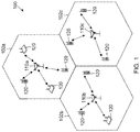
- Fig. 1 illustrates a wireless communication network 100, in accordance with various aspects of the disclosure.
- the wireless network 100 may include a number of base stations 110.
- a base station 110 may include an evolved Node B (eNodeB) in the LTE context, for example.
- eNodeB evolved Node B
- a base station may also be referred to as a base transceiver station or an access point.
- the base stations 110 communicate with user equipments (UEs) 120 as shown.
- a UE 120 may communicate with a base station 110 via an uplink and a downlink.
- the downlink (or forward link) refers to the communication link from a base station 110 to a UE 120.
- the uplink (or reverse link) refers to the communication link from a UE 120 to a base station 110.
- the UEs 120 may be dispersed throughout the wireless network 100, and each UE 120 may be stationary or mobile.
- a UE may also be referred to as a terminal, a mobile station, a subscriber unit, etc.
- a UE 120 may be a cellular phone, a smartphone, a personal digital assistant, a wireless modem, a laptop computer, a tablet computer, etc.
- the wireless communication network 100 is one example of a network to which various aspects of the disclosure apply.
- OFDM orthogonal frequency division multiplexing
- K multiple orthogonal frequency subbands.
- K orthogonal frequency subbands
- each subband is associated with a respective subcarrier that may be modulated with data. Up to K modulation symbols may be sent on the K subbands in each OFDM symbol period.
- a pilot, control, or data symbol may be a symbol known to both the transmitter and receiver and transmitted in a subband.
- any number and configuration of subbands may be used for pilot symbols, control symbols, and/or data symbols.
- half of the subbands may be used for pilot symbols, and the remaining subbands may be used for other purposes, such as to transmit data symbols or control symbols or the remaining subbands may not be used at all.
- the transmission and signaling techniques described herein may be used for a single-input single-output (SISO) system, a single-input multiple-output (SIMO) system, a multiple-input single-output (MISO) system, and a multiple-input multiple-output (MIMO) system. These techniques may be used for an OFDM-based system and for other multi-carrier communication systems. These techniques may also be used with various OFDM subband structures.
- SISO single-input single-output
- SIMO single-input multiple-output
- MISO multiple-input single-output
- MIMO multiple-input multiple-output
- FIG. 2 is a block diagram illustrating an exemplary transmitter system 210 (e.g., a base station 110) and a receiver system 250 (e.g., a UE 120) in a MIMO system 200, according to certain aspects of the present disclosure.
- a transmitter system 210 e.g., a base station 110
- a receiver system 250 e.g., a UE 120
- traffic data for a number of data streams is provided from a data source 212 to a transmit (TX) data processor 214.
- TX transmit
- each data stream is transmitted over a respective transmit antenna.
- TX data processor 214 formats, codes, and interleaves the traffic data for each data stream based on a particular coding scheme selected for that data stream to provide coded data.
- the coded data for each data stream may be multiplexed with pilot data and control data using OFDM techniques.
- the pilot and control data are typically a known data pattern that is processed in a known manner and may be used at the receiver system to estimate the channel response or other channel parameters. Pilot data may be formatted into pilot symbols. The number of pilot symbols and placement of pilot symbols within an OFDM symbol may be determined by instructions performed by processor 230. Similarly, control data may be formatted into control symbols. The number of control symbols and placement of control symbols within an OFDM symbol may be determined by instructions performed by processor 230.
- the multiplexed pilot and coded data for each data stream is then modulated (i.e., symbol mapped) based on a particular modulation scheme (e.g., BPSK, QSPK, M-PSK, or M-QAM) selected for that data stream to provide modulation symbols.
- a particular modulation scheme e.g., BPSK, QSPK, M-PSK, or M-QAM
- the data rate, coding, and modulation for each data stream may be determined by instructions performed by processor 230.
- the number of pilot symbols and placement of the pilot symbols in each frame may also be determined by instructions performed by processor 230.
- the number of control symbols and placement of the control symbols in each frame may also be determined by instructions performed by processor 230.
- the number of data symbols and placement of the data symbols in each frame may also be determined by instructions performed by processor 230.
- the processor 230 may be implemented using a general-purpose processor, a digital signal processor (DSP), an application specific integrated circuit (ASIC), a field programmable gate array (FPGA) or other programmable logic device, discrete gate or transistor logic, discrete hardware components, or any combination thereof designed to perform the functions described herein.
- the processor 230 may also be implemented as a combination of computing devices, e.g., a combination of a DSP and a microprocessor, a plurality of microprocessors, one or more microprocessors in conjunction with a DSP core, or any other such configuration.
- the transmitter system 210 further includes a memory 232.
- the memory 232 may be any electronic component capable of storing information and/or instructions.
- the memory 250 may include random access memory (RAM), read-only memory (ROM), flash memory devices in RAM, optical storage media, erasable programmable read-only memory (EPROM), registers, or combinations thereof.
- the memory 232 includes a non-transitory computer-readable medium.
- Instructions or code may be stored in the memory 232 that are executable by the processor 230.
- the terms "instructions” and “code” should be interpreted broadly to include any type of computer-readable statement(s).
- the terms “instructions” and “code” may refer to one or more programs, routines, sub-routines, functions, procedures, etc.
- “Instructions” and “code” may include a single computer-readable statement or many computer-readable statements.
- the modulation symbols for all data streams are then provided to a TX MIMO processor 220, that may further process the modulation symbols (e.g., for OFDM).
- TX MIMO processor 220 then provides N T modulation symbol streams to N T transmitters (TMTR) 222 a through 222 t .
- TMTR N T transmitters
- TX MIMO processor 220 applies beamforming weights to the symbols of the data streams and to the antenna from which the symbol is being transmitted.
- the transmitter system 210 includes only one antenna or multiple antennas.
- Each transmitter 222 receives and processes a respective symbol stream to provide one or more analog signals, and further conditions (e.g., amplifies, filters, and upconverts) the analog signals to provide a modulated signal suitable for transmission over the MIMO channel.
- N T modulated signals from transmitters 222 a through 222 t are then transmitted from N T antennas 224 a through 224 t , respectively.
- the techniques described herein apply also to systems with only one transmit antenna. Transmission using one antenna is simpler than the multi-antenna scenario. For example, there may be no need for TX MIMO processor 220 in a single antenna scenario.
- the transmitted modulated signals are received by N R antennas 252 a through 252 r and the received signal from each antenna 252 is provided to a respective receiver (RCVR) 254 a through 254 r .
- Each receiver 254 conditions (e.g., filters, amplifies, and downconverts) a respective received signal, digitizes the conditioned signal to provide samples, and further processes the samples to provide a corresponding "received" symbol stream.
- the techniques described herein also apply to embodiments of receiver system 250 having only one antenna 252.
- An RX data processor 260 then receives and processes the N R received symbol streams from NR receivers 254 based on a particular receiver processing technique to provide N T detected symbol streams.
- the RX data processor 260 then demodulates, deinterleaves, and decodes as necessary each detected symbol stream to recover the traffic data for the data stream.
- the processing by RX data processor 260 is complementary to that performed by TX MIMO processor 220 and TX data processor 214 at transmitter system 210.
- RX data processor 260 allows the processor 270 to generate reports such as channel state information (CSI) and/or a pilot request to provide to the TX Data Processor 238.
- Processor 270 formulates a reverse link message including the CSI and/or pilot request to transmit to the transmitter system.
- CSI channel state information
- pilot request to provide to the TX Data Processor 238.
- Processor 270 formulates a reverse link message including the CSI and/or pilot request to transmit to the transmitter system.
- the processor 270 may be implemented using a general-purpose processor, a digital signal processor (DSP), an application specific integrated circuit (ASIC), a field programmable gate array (FPGA) or other programmable logic device, discrete gate or transistor logic, discrete hardware components, or any combination thereof designed to perform the functions described herein.
- the processor 270 may also be implemented as a combination of computing devices, e.g., a combination of a DSP and a microprocessor, a plurality of microprocessors, one or more microprocessors in conjunction with a DSP core, or any other such configuration.
- the reverse link message may include various types of information regarding the communication link and/or the received data stream.
- the reverse link message is then processed by a TX data processor 238, which also receives traffic data for a number of data streams from a data source 236, modulated by a TX MIMO processor 280, conditioned by transmitters 254 a through 254 r , and transmitted back to transmitter system 210.
- the modulated signals from receiver system 250 are received by antennas 224, conditioned by receivers 222, demodulated by a demodulator 240, and processed by a RX data processor 242 to extract the reverse link message transmitted by the receiver system 250.
- Processor 230 determines a symbol density and placement based on information in the reverse link message.
- the symbol may be a pilot symbol, control symbol, or data symbol. Although the following examples may describe the symbol as a pilot symbol, this is not intended to be limiting and it should be understood that the symbol may be a control symbol or data symbol.
- An example of pilot symbol density is the number of pilot symbols per unit time or per unit frequency as discussed more fully below.
- An example pilot structure is a combination of pilot density and placement.
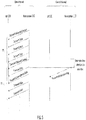
- Figs. 3A-3C illustrate downlink frame structures used in a wireless communication network (e.g., the wireless communication network shown in Fig. 1 ), in accordance with various aspects of the present disclosure.
- the transmission timeline for the downlink may be partitioned into units of transmission time intervals (TTIs).
- TTI may be related to the size of the data blocks passed from the higher network layers to the radio link layer.
- the duration of symbols, such as OFDM symbols is fixed, and there are a predetermined number of symbol periods during each TTI.
- each TTI may be any number of symbol periods, such as 8, 10, or 12 symbol periods, as examples.
- each TTI includes eight OFDM symbol periods, and the symbol periods are assigned indices 0 through 7 as shown.
- a transmission during a TTI may be referred to as a frame, a subframe, or a data block.
- An OFDM symbol period is an example time slot.
- Each resource element may cover one subcarrier in one symbol period and may be used to send one modulation symbol, which may be a real or complex value.
- Figs. 3A-3C illustrate three examples of signals transmitted using the illustrated frame structures.
- the examples in Figs. 3A-3C illustrate various pilot structures.
- there are 11 resource elements per OFDM symbol as an illustrative example.
- the resource elements are assigned indices 0 through 11 as shown. Pilot symbols are transmitted in the designated resource elements and are denoted by "P.”
- the remaining resource elements are available for other types of symbols, such as data symbols, or control symbols, or are simply unused or muted.
- the pilot structures in Figs. 3A-3C may represent a signal format transmitted from an antenna.
- the pilot structures may apply regardless of the number of antennas employed in the transmitting entity or the receiving entity.
- the signal is transmitted from the transmitting antenna and received at the receive antenna.
- the illustrated frame structures are transmitted from at least one antenna. Each antenna from among a plurality of antennas may transmit the same or a different pilot structure.
- the illustrated pilot structure will be received by a receive antenna, and may be part of a composite signal that is a sum of signals from a plurality of antennas.
- Fig. 3A illustrates a baseline pilot structure. Pilot symbols are transmitted in OFDM symbol periods 0 and 1 in each TTI. Within periods 0 and 1, pilot symbols are transmitted in resource elements 0, 4 and 8. The pilot symbols may be transmitted to a specific UE. The pilot symbols may be transmitted to a group of UEs The pilot symbols may be cell-specific reference signals. The pilot symbols may be used for channel estimation for coherent demodulation of the physical channel.
- Fig. 3B illustrates one technique to double the pilot density as compared to Fig. 3A .
- the pilot density is doubled by doubling the number of OFDM symbols within a TTI that contains pilot symbols. More specifically, pilot symbols are transmitted in the 4 th and 5 th periods within a TTI, in addition to the 0 th and 1 st periods. In essence, the number of pilot symbols is doubled by increasing the duty cycle or time density of pilot symbols.
- Fig. 3B represents but one example of many ways to double the duty cycle. For example, pilot symbols could be transmitted instead in the 1 st through 4 th symbol positions or any other combination of four symbol positions.
- Fig. 3C illustrates another technique to double the pilot density as compared to Fig. 3A .
- the pilot density is doubled by doubling the frequency occupancy as compared to Fig. 3A .
- pilot symbols there are pilot symbols in resource elements 0, 2, 4. 6, 8, and 10 in the 0 th and 1 st OFDM symbol periods in each TTI.
- the number of pilot symbols is doubled by increasing the density versus frequency within the symbol positions.
- Fig. 3C represents but one example of many ways to double the frequency density as compared to Fig. 3A .
- pilot symbols could be transmitted in the 1 st through 6 th resource elements or any other combination of six resource elements.
- Fig. 3A represents a pilot structure that is advantageous for channels with relatively low Doppler spread and relatively low channel delay-spread.
- Time variation of a channel is related to Doppler spread of the channel. Doppler spread may be caused, for example, by the differences in Doppler shifts of different components of a signal, if either the transmitter or receiver is in motion.
- Doppler spread increases, it is advantageous to increase the time density of pilot symbols.
- the higher the Doppler spread the faster a channel estimate becomes outdated.
- Increasing time density or duty cycle of pilot symbols allows a channel estimate to be updated more frequently, which is beneficial for higher delay spreads.
- Frequency variation of a channel is related to delay spread of the channel. As delay spread increases, it is advantageous to increase the frequency density of pilot symbols. This is because increases in delay spread result in increases in frequency selectivity of a channel. Increasing frequency density of pilot symbols allows channel estimates to better capture frequency selectivity caused by increased delay spread.
- pilot density may also be advantageous to vary pilot density on the basis of other parameters, such as signal-to-noise ratio (SNR) estimates, signal-to-interference-plus-noise (SINR) estimates, or interference estimates.
- SNR signal-to-noise ratio
- SINR signal-to-interference-plus-noise
- interference estimates For example, for increasing noise or interference values (or decreasing SNR or SINR), increasing numbers of pilot symbols are useful.
- Techniques can be used to estimate Doppler spread, delay spread, SNR, SINR, and interference in UEs. Any one of these techniques can be used to estimate these channel parameters, and these channel parameters are examples of CSI. One or more of these parameters can be used to select a downlink pilot structure. The selection of pilot structure can be made either in the UE or the base station. If the decision is to be made in the base station, channel parameter estimates can be fed back to the base station to allow the base station to make the decision on pilot structure. If the decision on pilot structure is to be made in the UE, a request for the determined pilot structure can be transmitted to the base station.
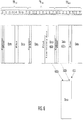
- Figs. 4A-4D illustrate example frame structures to accommodate as needed transmission of low-latency data.
- a frame may be transmitted in a TTI.
- the structure illustrated in TTI n represents an example baseline frame structure.
- the frames in Figs. 4A-4D may be transmitted from a base station, such as base station 110, to a UE, such as UE 120 or vice versa.
- the symbols in Figs. 4A-4D marked "data" may represent symbols transmitted as part of an on-going data session between a UE and a base station.
- the baseline frame structure in this example is one in which an OFDM symbol containing pilot and/or control symbols is transmitted in an alternating manner with data symbols.
- an OFDM symbol containing pilot and control symbols (labeled as "pilot” and "control”) is transmitted at symbol index 0
- an OFDM symbol containing a pilot symbol is transmitted at symbol index 4.
- low-latency data is available.
- low-latency data "trumps" or supersedes any data scheduled to be transmitted as part of the on-going data session.
- the data in the on-going session is relatively delay tolerant compared to the "low-latency" data.
- the punctured data includes pilot and control symbols
- the base station e.g., base station 110a determines that low-latency data is available to transmit during a TTI (e.g., TTI n+1 ).
- the base station informs a mobile station (e.g., UE 120) that the low-latency data will be transmitted during a time slot (e.g., OFDM symbol period 4 in TTI n+1 ) reserved for one or more symbols (e.g., pilot symbol) in TTI n+1 .
- the one or more symbols may be "pierced" or "punctured," and the base station may transmit the low-latency data during the time slot that was originally reserved for the one or more symbols and transmit the one or more symbols during a subsequent time slot. For example, as shown in Fig.
- the low latency data punctures the control symbol (in TTI n+1 )
- the punctured portion of the control symbol is transmitted during a subsequent time slot by puncturing the payload data.
- the low-latency data may "puncture" the one or more symbols (pilot or control or data) over the entire frequency range, as showed in Fig. 4A , or over a sub-band within the entire frequency band, as shown in Fig. 4B .
- the subsequent time slot may be in the same TTI or a subsequent TTI.
- the base station may transmit information through an indicator channel (I-Channel) to inform one or more receiving UEs that low-latency is available for transmission.
- the indicator channel may be transmitted over the entire frequency range or over a sub-band within the entire frequency band, as shown in Figs. 4C-D .
- the transmitted information may include details regarding a concurrent or later symbol or time slot during which the low-latency is being or will be transmitted.
- the indicator channel (I-Channel) may be transmitted over a sub-band of the frequency during the 0 th symbol of TTI n+1 along with the control channel.
- the indicator channel may include information that the low-latency data will later be transmitted during the 4 th symbol of TTI n+1 .
- the indicator channel (I-Channel) may be transmitted over a sub-band of the frequency during the 4 th symbol of TTI n+1 .
- the indicator channel may include information that the low-latency data is concurrently being transmitted during the 4 th symbol of TTI n+1 .
- the transmitted information may include details regarding the symbol or time slot during which the data punctured by the low-latency data will be transmitted.
- the indicator channel may include information that the punctured control data will later be transmitted during the 1 st symbol of TTI n+1 .
- the control data will be sent by puncturing the payload data as discussed with respect to Fig. 4B .
- the symbol Before determining that the low-latency data is available to transmit during a first time slot, the symbol is initially scheduled for transmission during the first time slot. Based on determining that low-latency data is available to transmit during the first time slot, the symbol that is originally scheduled (in the absence of low-latency data) for transmission during the first time slot may be "punctured" and transmitted during a subsequent time slot. It should be also understood that low-latency traffic puncturing data/control in the figures are for illustration purposes. In general, puncturing may happen at any symbol such as, for example, at a data symbol.
- the pilot may be moved any number of symbol periods later (e.g., two, three, etc. symbol periods later), as long as the UE is aware of the number of symbols that the pilot is moved.
- the UE may be made aware of the number of symbol periods for which the pilot (or control or data) is moved via a notification message communicated over the control channel. Alternatively, the UE may be made aware of the symbol period during which the pilot (or control or data) will be transmitted via the notification message.
- OFDM symbol period 5 in TTI n+1 is subsequent to OFDM symbol period 4 in TTI n+1 .
- Fig. 5 is a protocol diagram that illustrates example transmissions during the first two TTIs of Fig. 4 between a base station 110 and a UE 120.
- Fig. 5 illustrates a data channel that contains the transmissions of the first two TTIs of Fig. 4 as well as an associated control channel.
- a transmit notification message is transmitted over the control channel from the base station 110 to UE 120 as shown. The notification message is transmitted shortly after the base station 110 becomes aware of the low-latency data, due at least in part to the delay intolerance of the low-latency data.
- TTI n+2 there is no data to transmit during TTI n+2 , so there is no transmission.
- the base station becomes aware that more low-latency data is available.
- the UE is informed of the low-latency data via a control channel as discussed earlier.
- the low-latency data supersedes the pilot and control for the following TTI, TTI n+3 , so the pilot and control are moved from OFDM symbol period 0 to OFDM period 1 to make room for the low-latency data.
- the process of transmitting frames during TTIs and inserting low-latency data as needed may continue indefinitely.
- bursty interference occurs during a downlink transmission.
- Bursty interference can include interference that occurs in short spurts or time intervals over a short period of time. Bursty interference may appear for only a brief period of time to affect some signals but may not appear over such a sustained period of time that the system should adapt to the level of interference as a long-term statistic.
- bursty interference is a non-persistent burst data transmission that may occur nearby in another cell that becomes co-channel interference in the cell of interest. There may be a small amount of data (e.g., an email or small data file) to convey in a bursty data transmission.
- a data symbol may be punctured and accordingly shifted to a set of subsequent time slots in the current short TTI and/or to a set of time slots in the next short TTI.
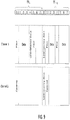
- Fig. 6 illustrates an example frame structure to accommodate as needed transmission of low-latency data in association with a punctured data symbol.
- the structure illustrated in TTI n+4 may be the TTI after TTI n+3 illustrated in FIG. 4 .
- an OFDM symbol containing pilot and control symbols (labeled as "pilot” and “control”) is transmitted at symbol index 0
- an OFDM symbol containing data symbols (labeled as "data”) is transmitted at symbol indexes 1-3 and 5-7
- an OFDM symbol containing a pilot symbol is transmitted at symbol index 4.
- low-latency data is available.
- the base station e.g., base station 110a
- TTI e.g., TTI n+5
- data symbols are punctured.
- the base station informs a mobile station (e.g., UE 120) that the low-latency data will be transmitted during a time slot (e.g., OFDM symbol period 5 in TTI n+5 ) originally reserved for a data symbol 602 in TTI n+5 .
- a time slot e.g., OFDM symbol period 5 in TTI n+5
- Data or a data symbol may include a set of one or more code blocks.
- data symbol 602 includes a first subset of code blocks 602a and a second subset of code blocks 602b.
- the base station may shift the data symbol (and subsequent data symbols of the data to be transmitted during that TTI (e.g., TTI n+5 ) such that the low-latency data is transmitted in one or more of the time slots reserved for the data symbol, and accordingly the data symbol is transmitted after the low-latency data.
- TTI e.g., TTI n+5
- the base station may transmit at least one code block included in data symbol 602 during a set of time slots in TTI n+5 .
- set of code blocks 602 may be transmitted in one or more of the remaining available time slots in TTI n+5 .
- set of code blocks 602 "fits" within time slots 6 and 7 in TTI n+5 , and may be transmitted during time slots 6 and 7 in TTI n+5 .
- the base station may transmit all code blocks included in data symbol 602 during time slots 6 and 7 in TTI n+5 .
- set of code blocks 602 does not "fit" within time slots 6 and 7 in TTI n+5 , and in particular may be too large to be transmitted within these two remaining time slots.
- set of code blocks 602 may need to be transmitted during more than two time slots in order for the base station to transmit all of the code blocks included in data symbol 602.
- the base station determines that the quantity of time slots to transmit data symbol 602 is greater than a remaining quantity of available time slots in current TTI n+5 .
- the base station may determine that two available time slots remain in current TTI n+5 and that transmission of code blocks 602a and 602b consumes three time slots.
- First set of code blocks 602a and second set of code blocks 602b are transmitted over different sub-bands (e.g., in a multiplexing context). Accordingly, only one set of the code blocks 602a/b may be punctured by the low-latency data being on the same sub-band. In an example, both sets of code blocks 602a and 602b may be transmitted during the next time slot. In another example, only the set of code blocks that was punctured is transmitted during the next time slot. In this example, the base station may send signaling/instructions to the UE to indicate that the set of code blocks received in the later time slot should be combined with the previously received set of code blocks to complete the data set.
- the base station may inform the mobile station that a first subset of code blocks 602a included in data symbol 602 will be transmitted during a first set of time slots in current TTI n+5 and that a second subset of code blocks 602b included in data symbol 602 will be transmitted during a second set of time slots in a subsequent TTI (e.g., TTI n+6 ).
- the beginning time slot of a frame may include pilot and control data.
- the base station may transmit one or more symbols (e.g., pilot and control symbols) during time slot 0 in TTI n+6 and transmit second subset of code blocks 602b at the beginning of the time slot reserved for data symbols (e.g., during time slot 1 in TTI n+6 ).
- the base station may transmit the pilot and control symbols before the data symbol so that the UE knows when and how the data symbols will be transmitted and how to decode the data symbol once received.
- the time slot including the pilot and control symbols precede the one or more time slots including second subset of code blocks 602b.
- first subset of code blocks 602a and second subset of code blocks 602b are transmitted during different TTIs. Additionally, second subset of code blocks 602b expands the entire data portion of TTI n+6 in time slots 1-3. If code blocks included in a data symbol are shifted to the next TTI, the shifted code blocks may be aligned at the TTI level. The length of the code blocks may be longer to fit the entire data portion of the TTI with smaller resource allocation. Second subset of code blocks 602b may expand the entire data portion of the TTI along with new data. In an example, if no more data is to be transmitted during the TTI, padding may be applied.
- UE may combine set of code blocks 602A received during slots 6 and 7 of TTI n+5 with set of code blocks 602B received during slots 1-3 of TTI n+6 to process data symbol 602.
- the UE may receive the indication that first subset of code blocks 602a included in data symbol 602 will be transmitted during a first set of time slots in a first TTI and an indication that second subset of code blocks 602b included in data symbol 602 will be transmitted during a second TTI.
- the second TTI may be the next TTI after the first TTI.
- the UE may receive first subset of code blocks 602a during the first set of time slots in the first TTI, receive one or more symbols (e.g., pilot and control symbols) during a first time slot in the second TTI, and receive second subset of code blocks 602b during the second set of time slots in the second TTI.
- the first time slot including the one or more symbols (e.g., pilot and control symbols) in the second TTI precedes the second set of time slots in the second TTI.
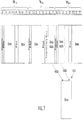
- Fig. 7 illustrates another example frame structure to accommodate as needed transmission of low-latency data in association with a punctured data symbol.
- data symbol 602 is punctured. If no more data is to be transmitted during slot 3 of TTI n+5 , the amount of data transmitted may be reduced by not transmitting data during this time slot.
- time slot 3 in TTI n+6 may be empty (or filled with only pilot symbols) because all of the code blocks of data symbol 602 may have been transmitted to the UE.
- Fig. 8 illustrates an example frame structure to accommodate as needed transmission of low-latency data in association with a punctured control symbol.
- TTI n an OFDM symbol containing a control symbol is transmitted at symbol index 0
- an OFDM symbol containing a pilot (for data) symbol is transmitted at symbol index 1
- data symbols are transmitted at OFDM symbol indexes 2 and 3
- an OFDM symbol containing a pilot symbol is transmitted at symbol index 4
- an OFDM symbol containing a data symbol is transmitted at symbol indexes 5-7.
- the punctured data includes a control symbol.
- the low-latency data supersedes the control data for TTI n+1 in Fig. 8 and is transmitted in slot 0 in TTI n+1 , at the slot originally intended for the control symbol.
- the control symbol can be moved from OFDM symbol period 0 to OFDM period 1 to make room for the low-latency data
- the pilot symbol can be moved from OFDM symbol period 1 to OFDM period 2 to make room for the punctured control symbol.
- the data symbol can be transmitted in slot 3 in TTI n+1 .
- the control symbol and pilot symbol are transmitted during the same symbol period such that both the control symbol and pilot symbol are moved from a scheduled OFDM symbol period (e.g., OFDM symbol period 0) to a subsequent OFDM symbol period (e.g., OFDM symbol period 1) following transmission of the low-latency data.
- Fig. 9 illustrates an example frame structure to accommodate as needed transmission of low-latency data in association with a punctured pilot or control symbol. Pilot (for data) and control symbols may be transmitted during the same period but using different channels (e.g., different frequency bands). For example, as illustrated in Fig. 9 , pilot symbols may be transmitted on channel 1 and control symbols may be transmitted on channel 2.
- low-latency data may be transmitted over only one of the channels such that the low-latency data punctures one of the symbols but not the other.
- low-latency data may puncture only the pilot symbol on channel 1 but not the control symbol on channel 2.
- low-latency data may puncture only the control symbol on channel 2 but not the pilot symbol on channel 1.
- the low-latency data may be transmitted over both channels such that the pilot symbol and control symbol are punctured.
- an OFDM symbol containing a control symbol is transmitted at symbol index 0 on channel 2
- an OFDM symbol containing a pilot symbol is transmitted at symbol index 0 on channel 1
- an OFDM symbol containing a data symbol is transmitted at symbol indexes 1-3 on channel 2.
- the next pilot symbol scheduled for symbol index 4 on channel 1 may be punctured by low-latency data.
- a pilot symbol may be punctured and moved over from its original symbol index 4 on channel 1 to symbol index 5 on channel 1 to make room for the low-latency data.
- the low-latency data is transmitted at symbol index 4 on channel 1, and the pilot symbol is transmitted at symbol index 5 on channel 1.
- low-latency data is available for transmission in TTI n+1 .
- the pilot and control symbols that are scheduled to be transmitted at symbol index 0 on channels 1 and 2 are punctured. Accordingly, the low-latency data is transmitted at symbol index 0 over both channels 1 and 2.
- the pilot and control symbols can be moved from symbol period 0 to symbol period 1 to make room for the low-latency data.
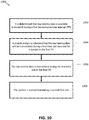
- Fig. 10 is a flowchart illustrating an exemplary method 1000 for adapting structures (e.g., pilot structures, control structures, and/or data structures).
- the method 1000 may be implemented in a base station, such as base station 110.
- the base station communicates with a UE, such as UE 120, according to method 1000.
- the method may be implemented in transmitter system 210. Instructions or code may be stored in the memory 232 that are executable by the processor 230 in transmitter system 210 to implement the method 1000. It should be understood that method 1000 is not meant to be limiting and may be used in other applications.
- the method begins in a block 1002.
- block 1002 it is determined that low-latency data is available to transmit during a first TTI.
- a mobile station is informed that the low-latency data will be transmitted during a first time slot reserved for a symbol in the first TTI.
- the symbol may be, for example, a pilot symbol, control symbol, or data symbol.
- the low-latency data is transmitted during the first time slot in the first TTI.
- the symbol is transmitted during a second time slot.
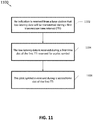
- Fig. 11 is a flowchart illustrating an exemplary method 1100 for adapting structures (e.g., pilot structures, control structures, and/or data structures).
- the method 1100 may be implemented in a UE, such as UE 120.
- a UE communicates with a base station, such as base station 110, according to the method 1100.
- the method may be implemented in the receiver system 250. Instructions or code may be stored in the memory 272 that are executable by the processor 270 in the receiver system 250 to implement the method 1100. It should be understood that method 1100 is not meant to be limiting and may be used in other applications.
- the method 1100 begins in a block 1102.
- an indication is received from a base station that low-latency data will be transmitted during a first TTI.
- the low-latency data is received during a first time slot of the first TTI reserved for a symbol.
- the symbol may be, for example, a pilot symbol, control symbol, or data symbol.
- the symbol is received during a second time slot of the first TTI.
- Information and signals may be represented using any of a variety of different technologies and techniques.
- data, instructions, commands, information, signals, bits, symbols, and chips that may be referenced throughout the above description may be represented by voltages, currents, electromagnetic waves, magnetic fields or particles, optical fields or particles, or any combination thereof.
- a general-purpose processor may be a microprocessor, but in the alternative, the processor may be any conventional processor, controller, microcontroller, or state machine.
- a processor may also be implemented as a combination of computing devices (e.g., a combination of a DSP and a microprocessor, multiple microprocessors, one or more microprocessors in conjunction with a DSP core, or any other such configuration).
- the functions described herein may be implemented in hardware, software executed by a processor, firmware, or any combination thereof. If implemented in software executed by a processor, the functions may be stored on or transmitted over as one or more instructions or code on a computer-readable medium. Other examples and implementations are within the scope of the disclosure and appended claims. For example, due to the nature of software, functions described above can be implemented using software executed by a processor, hardware, firmware, hardwiring, or combinations of any of these. Features implementing functions may also be physically located at various positions, including being distributed such that portions of functions are implemented at different physical locations.
Landscapes
- Engineering & Computer Science (AREA)
- Signal Processing (AREA)
- Computer Networks & Wireless Communication (AREA)
- Mobile Radio Communication Systems (AREA)
Description
- This application relates to wireless communication systems, and more particularly to adaptive signaling and flexible frame formats and network protocols for accommodating changes in signal structure and/or scheduling of transmissions.
- To achieve sufficient performance in wireless communication systems, it is sometimes useful to characterize the wireless channel. For example, a transmitting entity may need an estimate of one or more channel parameters to perform spatial processing, precoding, or adaptive modulation and coding in order to transmit data to a receiving entity. The receiving entity may need an estimate of one or more channel parameters to properly demodulate transmitted signals in order to recover transmitted data.
- Pilots may be inserted in a transmitted data stream to assist a receiving entity with various functions, including not only channel estimation but also timing and frequency offset acquisition as examples. A pilot typically includes one or more modulation symbols known to both the transmitting entity and the receiving entity that are transmitted in a known manner.
- Conventional systems employ a fixed pilot structure that provides an adequate number and distribution of pilot symbols for most receiving entities under most channel conditions. However, the pilot structures may be inadequate for challenging channel conditions, and the pilot structures may waste system resources during more benign channel conditions. Thus, there is a need for techniques to better match pilot structures to channel conditions.
-
US 2009/029624 A1 describes a method for generating a pilot pattern for data to be transmitted in an orthogonal frequency-division multiplexing (OFDM) based communication system including allocating pilot symbols for a plurality of data streams to form a plurality of pilot clusters in a pilot pattern.WO 2016/069208 A1 discusses pilot reconfiguration and retransmission in wireless networks. - The invention is defined by the appended independent claims.
A method is defined by theindependent claim 1 while the corresponding apparatus is defined by the independent claim 13. -
-
Fig. 1 illustrates a wireless communication network in accordance with various aspects of the present disclosure. -
Fig. 2 is a block diagram illustrating an exemplary transmitter system in accordance with various aspects of the present disclosure. -
Figs. 3A-3C illustrate downlink frame structures used in a wireless communication network in accordance with various aspects of the present disclosure. -
Figs. 4A-4D illustrate frame structures to accommodate as needed transmission of low-latency data in accordance with various aspects of the present disclosure. -
Fig. 5 is a protocol diagram that illustrates example transmissions during the first two TTIs ofFigs. 4A-4D between a base station and a UE in accordance with various aspects of the present disclosure. -
Fig. 6 illustrates an example frame structure to accommodate as needed transmission of low-latency data in association with a punctured data symbol in accordance with various aspects of the present disclosure. -
Fig. 7 illustrates another example frame structure to accommodate as needed transmission of low-latency data in association with a punctured data symbol in accordance with various aspects of the present disclosure. -
Fig. 8 illustrates an example frame structure to accommodate as needed transmission of low-latency data in association with a punctured control symbol in accordance with various aspects of the present disclosure. -
Fig. 9 illustrates an example frame structure to accommodate as needed transmission of low-latency data in association with a punctured pilot or control symbol. -
Fig. 10 is a flowchart illustrating an exemplary method for adapting structures in accordance with various aspects of the present disclosure. -
Fig. 11 is a flowchart illustrating an exemplary method for adapting structures in accordance with various aspects of the present disclosure. - The detailed description set forth below, in connection with the appended drawings, is intended as a description of various configurations and is not intended to represent the only configurations in which the concepts described herein may be practiced. The detailed description includes specific details for the purpose of providing a thorough understanding of the various concepts. However, it will be apparent to those skilled in the art that these concepts may be practiced without these specific details. In some instances, well-known structures and components are shown in block diagram form in order to avoid obscuring such concepts.
- The techniques described herein may be used for various wireless communication networks such as CDMA, TDMA, FDMA, OFDMA, SC-FDMA and other networks. The terms "network" and "system" are often used interchangeably. A CDMA network may implement a radio technology such as Universal Terrestrial Radio Access (UTRA), cdma2000, etc. UTRA includes Wideband CDMA (WCDMA) and other variants of CDMA. cdma2000 covers IS-2000, IS-95 and IS-856 standards. A TDMA network may implement a radio technology such as Global System for Mobile Communications (GSM). An OFDMA network may implement a radio technology such as Evolved UTRA (E-UTRA), Ultra Mobile Broadband (UMB), IEEE 802.11 (Wi-Fi), IEEE 802.16 (WiMAX), IEEE 802.20, Flash-OFDMA, etc. UTRA and E-UTRA are part of Universal Mobile Telecommunication System (UMTS). 3GPP Long Term Evolution (LTE) and LTE-Advanced (LTE-A) are new releases of UMTS that use E-UTRA. UTRA, E-UTRA, UMTS, LTE, LTE-A and GSM are described in documents from an organization named "3rd Generation Partnership Project" (3GPP). CDMA2000 and UMB are described in documents from an organization named "3rd Generation Partnership Project 2" (3GPP2). The techniques described herein may be used for the wireless networks and radio technologies mentioned above as well as other wireless networks and radio technologies, such as a next generation (e.g., 5th Generation (5G)) network.
- This disclosure relates generally to adaptive signaling (e.g., pilot signaling, control signaling or data signaling) and flexible frame formats and network protocols for accommodating changes in signal structure and/or scheduling. Adaptive techniques are disclosed herein that attempt to tune a number of pilot symbols and the distribution thereof over time and frequency resources to channel conditions in an effort to minimize system overhead while at the same time providing enough pilot symbols for receivers to function sufficiently.
-
Fig. 1 illustrates awireless communication network 100, in accordance with various aspects of the disclosure. Thewireless network 100 may include a number ofbase stations 110. Abase station 110 may include an evolved Node B (eNodeB) in the LTE context, for example. A base station may also be referred to as a base transceiver station or an access point. - The
base stations 110 communicate with user equipments (UEs) 120 as shown. A UE 120 may communicate with abase station 110 via an uplink and a downlink. The downlink (or forward link) refers to the communication link from abase station 110 to a UE 120. The uplink (or reverse link) refers to the communication link from a UE 120 to abase station 110. - The UEs 120 may be dispersed throughout the
wireless network 100, and each UE 120 may be stationary or mobile. A UE may also be referred to as a terminal, a mobile station, a subscriber unit, etc. A UE 120 may be a cellular phone, a smartphone, a personal digital assistant, a wireless modem, a laptop computer, a tablet computer, etc. Thewireless communication network 100 is one example of a network to which various aspects of the disclosure apply. - This disclosure is directed to any type of modulation scheme, but orthogonal frequency division multiplexing (OFDM) is used as a representative modulation. OFDM is a multi-carrier modulation technique that effectively partitions the overall system bandwidth into multiple (K) orthogonal frequency subbands. These subbands may also be referred to as tones, subcarriers, bins, and frequency channels. With OFDM, each subband is associated with a respective subcarrier that may be modulated with data. Up to K modulation symbols may be sent on the K subbands in each OFDM symbol period.
- A pilot, control, or data symbol may be a symbol known to both the transmitter and receiver and transmitted in a subband. For an OFDM symbol with K subbands, any number and configuration of subbands may be used for pilot symbols, control symbols, and/or data symbols. For example, half of the subbands may be used for pilot symbols, and the remaining subbands may be used for other purposes, such as to transmit data symbols or control symbols or the remaining subbands may not be used at all.
- The transmission and signaling techniques described herein may be used for a single-input single-output (SISO) system, a single-input multiple-output (SIMO) system, a multiple-input single-output (MISO) system, and a multiple-input multiple-output (MIMO) system. These techniques may be used for an OFDM-based system and for other multi-carrier communication systems. These techniques may also be used with various OFDM subband structures.
-
FIG. 2 is a block diagram illustrating an exemplary transmitter system 210 (e.g., a base station 110) and a receiver system 250 (e.g., a UE 120) in aMIMO system 200, according to certain aspects of the present disclosure. At the transmitter system 210, traffic data for a number of data streams is provided from adata source 212 to a transmit (TX) data processor 214. - In a downlink transmission, for example, each data stream is transmitted over a respective transmit antenna. TX data processor 214 formats, codes, and interleaves the traffic data for each data stream based on a particular coding scheme selected for that data stream to provide coded data.
- The coded data for each data stream may be multiplexed with pilot data and control data using OFDM techniques. The pilot and control data are typically a known data pattern that is processed in a known manner and may be used at the receiver system to estimate the channel response or other channel parameters. Pilot data may be formatted into pilot symbols. The number of pilot symbols and placement of pilot symbols within an OFDM symbol may be determined by instructions performed by
processor 230. Similarly, control data may be formatted into control symbols. The number of control symbols and placement of control symbols within an OFDM symbol may be determined by instructions performed byprocessor 230. - The multiplexed pilot and coded data for each data stream is then modulated (i.e., symbol mapped) based on a particular modulation scheme (e.g., BPSK, QSPK, M-PSK, or M-QAM) selected for that data stream to provide modulation symbols. The data rate, coding, and modulation for each data stream may be determined by instructions performed by
processor 230. The number of pilot symbols and placement of the pilot symbols in each frame may also be determined by instructions performed byprocessor 230. Similarly, the number of control symbols and placement of the control symbols in each frame may also be determined by instructions performed byprocessor 230. Similarly, the number of data symbols and placement of the data symbols in each frame may also be determined by instructions performed byprocessor 230. - The
processor 230 may be implemented using a general-purpose processor, a digital signal processor (DSP), an application specific integrated circuit (ASIC), a field programmable gate array (FPGA) or other programmable logic device, discrete gate or transistor logic, discrete hardware components, or any combination thereof designed to perform the functions described herein. Theprocessor 230 may also be implemented as a combination of computing devices, e.g., a combination of a DSP and a microprocessor, a plurality of microprocessors, one or more microprocessors in conjunction with a DSP core, or any other such configuration. - The transmitter system 210 further includes a
memory 232. Thememory 232 may be any electronic component capable of storing information and/or instructions. For example, thememory 250 may include random access memory (RAM), read-only memory (ROM), flash memory devices in RAM, optical storage media, erasable programmable read-only memory (EPROM), registers, or combinations thereof. Thememory 232 includes a non-transitory computer-readable medium. - Instructions or code may be stored in the
memory 232 that are executable by theprocessor 230. The terms "instructions" and "code" should be interpreted broadly to include any type of computer-readable statement(s). For example, the terms "instructions" and "code" may refer to one or more programs, routines, sub-routines, functions, procedures, etc. "Instructions" and "code" may include a single computer-readable statement or many computer-readable statements. - The modulation symbols for all data streams are then provided to a
TX MIMO processor 220, that may further process the modulation symbols (e.g., for OFDM).TX MIMO processor 220 then provides NT modulation symbol streams to NT transmitters (TMTR) 222 a through 222 t .TX MIMO processor 220 applies beamforming weights to the symbols of the data streams and to the antenna from which the symbol is being transmitted. The transmitter system 210 includes only one antenna or multiple antennas. - Each transmitter 222 receives and processes a respective symbol stream to provide one or more analog signals, and further conditions (e.g., amplifies, filters, and upconverts) the analog signals to provide a modulated signal suitable for transmission over the MIMO channel. NT modulated signals from transmitters 222a through 222t are then transmitted from NT antennas 224 a through 224 t, respectively. The techniques described herein apply also to systems with only one transmit antenna. Transmission using one antenna is simpler than the multi-antenna scenario. For example, there may be no need for
TX MIMO processor 220 in a single antenna scenario. - At
receiver system 250, the transmitted modulated signals are received by NR antennas 252 a through 252 r and the received signal from each antenna 252 is provided to a respective receiver (RCVR) 254 a through 254 r. Each receiver 254 conditions (e.g., filters, amplifies, and downconverts) a respective received signal, digitizes the conditioned signal to provide samples, and further processes the samples to provide a corresponding "received" symbol stream. The techniques described herein also apply to embodiments ofreceiver system 250 having only one antenna 252. - An
RX data processor 260 then receives and processes the NR received symbol streams from NR receivers 254 based on a particular receiver processing technique to provide NT detected symbol streams. TheRX data processor 260 then demodulates, deinterleaves, and decodes as necessary each detected symbol stream to recover the traffic data for the data stream. The processing byRX data processor 260 is complementary to that performed byTX MIMO processor 220 and TX data processor 214 at transmitter system 210. - Information provided by the
RX data processor 260 allows theprocessor 270 to generate reports such as channel state information (CSI) and/or a pilot request to provide to the TX Data Processor 238.Processor 270 formulates a reverse link message including the CSI and/or pilot request to transmit to the transmitter system. - The
processor 270 may be implemented using a general-purpose processor, a digital signal processor (DSP), an application specific integrated circuit (ASIC), a field programmable gate array (FPGA) or other programmable logic device, discrete gate or transistor logic, discrete hardware components, or any combination thereof designed to perform the functions described herein. Theprocessor 270 may also be implemented as a combination of computing devices, e.g., a combination of a DSP and a microprocessor, a plurality of microprocessors, one or more microprocessors in conjunction with a DSP core, or any other such configuration. - The reverse link message may include various types of information regarding the communication link and/or the received data stream. The reverse link message is then processed by a TX data processor 238, which also receives traffic data for a number of data streams from a data source 236, modulated by a TX MIMO processor 280, conditioned by transmitters 254 a through 254 r , and transmitted back to transmitter system 210.
- At transmitter system 210, the modulated signals from
receiver system 250 are received by antennas 224, conditioned by receivers 222, demodulated by a demodulator 240, and processed by a RX data processor 242 to extract the reverse link message transmitted by thereceiver system 250.Processor 230 then determines a symbol density and placement based on information in the reverse link message. The symbol may be a pilot symbol, control symbol, or data symbol. Although the following examples may describe the symbol as a pilot symbol, this is not intended to be limiting and it should be understood that the symbol may be a control symbol or data symbol. An example of pilot symbol density is the number of pilot symbols per unit time or per unit frequency as discussed more fully below. An example pilot structure is a combination of pilot density and placement. -
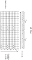
Figs. 3A-3C illustrate downlink frame structures used in a wireless communication network (e.g., the wireless communication network shown inFig. 1 ), in accordance with various aspects of the present disclosure. The transmission timeline for the downlink may be partitioned into units of transmission time intervals (TTIs). A TTI may be related to the size of the data blocks passed from the higher network layers to the radio link layer. The duration of symbols, such as OFDM symbols, is fixed, and there are a predetermined number of symbol periods during each TTI. For example, each TTI may be any number of symbol periods, such as 8, 10, or 12 symbol periods, as examples. InFigs. 3A-3C , each TTI includes eight OFDM symbol periods, and the symbol periods are assignedindices 0 through 7 as shown. A transmission during a TTI may be referred to as a frame, a subframe, or a data block. An OFDM symbol period is an example time slot. - A number of resource elements may be available in each OFDM symbol period. Each resource element may cover one subcarrier in one symbol period and may be used to send one modulation symbol, which may be a real or complex value.
-
Figs. 3A-3C illustrate three examples of signals transmitted using the illustrated frame structures. In particular, the examples inFigs. 3A-3C illustrate various pilot structures. In each ofFigs. 3A-3C , there are 11 resource elements per OFDM symbol as an illustrative example. The resource elements are assignedindices 0 through 11 as shown. Pilot symbols are transmitted in the designated resource elements and are denoted by "P." The remaining resource elements are available for other types of symbols, such as data symbols, or control symbols, or are simply unused or muted. - The pilot structures in
Figs. 3A-3C may represent a signal format transmitted from an antenna. The pilot structures may apply regardless of the number of antennas employed in the transmitting entity or the receiving entity. For example, in a SISO system, the signal is transmitted from the transmitting antenna and received at the receive antenna. As another example, in a MIMO system, the illustrated frame structures are transmitted from at least one antenna. Each antenna from among a plurality of antennas may transmit the same or a different pilot structure. The illustrated pilot structure will be received by a receive antenna, and may be part of a composite signal that is a sum of signals from a plurality of antennas. -
Fig. 3A illustrates a baseline pilot structure. Pilot symbols are transmitted inOFDM symbol periods periods resource elements -
Fig. 3B illustrates one technique to double the pilot density as compared toFig. 3A . InFig. 3B , the pilot density is doubled by doubling the number of OFDM symbols within a TTI that contains pilot symbols. More specifically, pilot symbols are transmitted in the 4th and 5th periods within a TTI, in addition to the 0th and 1st periods. In essence, the number of pilot symbols is doubled by increasing the duty cycle or time density of pilot symbols.Fig. 3B represents but one example of many ways to double the duty cycle. For example, pilot symbols could be transmitted instead in the 1st through 4th symbol positions or any other combination of four symbol positions. -
Fig. 3C illustrates another technique to double the pilot density as compared toFig. 3A . InFig. 3C , the pilot density is doubled by doubling the frequency occupancy as compared toFig. 3A . More specifically, there are pilot symbols inresource elements Fig. 3C represents but one example of many ways to double the frequency density as compared toFig. 3A . For example, pilot symbols could be transmitted in the 1st through 6th resource elements or any other combination of six resource elements. - There are situations in which it would be advantageous to vary the frequency density of pilots as opposed to time density of pilots and vice versa.
Fig. 3A represents a pilot structure that is advantageous for channels with relatively low Doppler spread and relatively low channel delay-spread. Time variation of a channel is related to Doppler spread of the channel. Doppler spread may be caused, for example, by the differences in Doppler shifts of different components of a signal, if either the transmitter or receiver is in motion. As Doppler spread increases, it is advantageous to increase the time density of pilot symbols. One reason is because the higher the Doppler spread, the faster a channel estimate becomes outdated. Increasing time density or duty cycle of pilot symbols allows a channel estimate to be updated more frequently, which is beneficial for higher delay spreads. - Frequency variation of a channel is related to delay spread of the channel. As delay spread increases, it is advantageous to increase the frequency density of pilot symbols. This is because increases in delay spread result in increases in frequency selectivity of a channel. Increasing frequency density of pilot symbols allows channel estimates to better capture frequency selectivity caused by increased delay spread.
- It may also be advantageous to vary pilot density on the basis of other parameters, such as signal-to-noise ratio (SNR) estimates, signal-to-interference-plus-noise (SINR) estimates, or interference estimates. For example, for increasing noise or interference values (or decreasing SNR or SINR), increasing numbers of pilot symbols are useful.
- Techniques can be used to estimate Doppler spread, delay spread, SNR, SINR, and interference in UEs. Any one of these techniques can be used to estimate these channel parameters, and these channel parameters are examples of CSI. One or more of these parameters can be used to select a downlink pilot structure. The selection of pilot structure can be made either in the UE or the base station. If the decision is to be made in the base station, channel parameter estimates can be fed back to the base station to allow the base station to make the decision on pilot structure. If the decision on pilot structure is to be made in the UE, a request for the determined pilot structure can be transmitted to the base station.
-
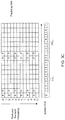
Figs. 4A-4D illustrate example frame structures to accommodate as needed transmission of low-latency data. A frame may be transmitted in a TTI. The structure illustrated in TTIn represents an example baseline frame structure. The frames inFigs. 4A-4D may be transmitted from a base station, such asbase station 110, to a UE, such asUE 120 or vice versa. The symbols inFigs. 4A-4D marked "data" may represent symbols transmitted as part of an on-going data session between a UE and a base station. The baseline frame structure in this example is one in which an OFDM symbol containing pilot and/or control symbols is transmitted in an alternating manner with data symbols. In TTIn, an OFDM symbol containing pilot and control symbols (labeled as "pilot" and "control") is transmitted atsymbol index 0, and an OFDM symbol containing a pilot symbol is transmitted atsymbol index 4. - In TTIn+1, low-latency data is available. In effect, low-latency data "trumps" or supersedes any data scheduled to be transmitted as part of the on-going data session. The data in the on-going session is relatively delay tolerant compared to the "low-latency" data. In the example illustrated in
Fig. 4A , the punctured data includes pilot and control symbols The base station (e.g.,base station 110a) determines that low-latency data is available to transmit during a TTI (e.g., TTIn+1). In some examples, based on the determination that low-latency data is available to transmit during TTIn+1, the base station informs a mobile station (e.g., UE 120) that the low-latency data will be transmitted during a time slot (e.g.,OFDM symbol period 4 in TTIn+1) reserved for one or more symbols (e.g., pilot symbol) in TTIn+1. The one or more symbols may be "pierced" or "punctured," and the base station may transmit the low-latency data during the time slot that was originally reserved for the one or more symbols and transmit the one or more symbols during a subsequent time slot. For example, as shown inFig. 4B , when the low latency data punctures the control symbol (in TTIn+1), the punctured portion of the control symbol is transmitted during a subsequent time slot by puncturing the payload data. In various embodiments, the low-latency data may "puncture" the one or more symbols (pilot or control or data) over the entire frequency range, as showed inFig. 4A , or over a sub-band within the entire frequency band, as shown inFig. 4B . The subsequent time slot may be in the same TTI or a subsequent TTI. - Upon determination that low-latency data is available for transmission, the base station may transmit information through an indicator channel (I-Channel) to inform one or more receiving UEs that low-latency is available for transmission. The indicator channel may be transmitted over the entire frequency range or over a sub-band within the entire frequency band, as shown in
Figs. 4C-D . The transmitted information may include details regarding a concurrent or later symbol or time slot during which the low-latency is being or will be transmitted. For example, as shown inFig. 4C , the indicator channel (I-Channel) may be transmitted over a sub-band of the frequency during the 0th symbol of TTIn+1 along with the control channel. As discussed above, the indicator channel may include information that the low-latency data will later be transmitted during the 4th symbol of TTIn+1. Similarly, as shown inFig. 4D , the indicator channel (I-Channel) may be transmitted over a sub-band of the frequency during the 4th symbol of TTIn+1. As discussed above, the indicator channel may include information that the low-latency data is concurrently being transmitted during the 4th symbol of TTIn+1. - In addition, the transmitted information may include details regarding the symbol or time slot during which the data punctured by the low-latency data will be transmitted. For example, as shown in
Fig. 4C , the indicator channel may include information that the punctured control data will later be transmitted during the 1st symbol of TTIn+1. In this case, the control data will be sent by puncturing the payload data as discussed with respect toFig. 4B . Although it is critical to indicate the transmission of low-latency data in the current or later symbol because low-latency data is more delay sensitive, it is also critical to inform the UE of the symbol period or time slot during which the punctured portion of the pilot or control data will be transmitted. - Before determining that the low-latency data is available to transmit during a first time slot, the symbol is initially scheduled for transmission during the first time slot. Based on determining that low-latency data is available to transmit during the first time slot, the symbol that is originally scheduled (in the absence of low-latency data) for transmission during the first time slot may be "punctured" and transmitted during a subsequent time slot. It should be also understood that low-latency traffic puncturing data/control in the figures are for illustration purposes. In general, puncturing may happen at any symbol such as, for example, at a data symbol.
- As part of an example network protocol, there may be a separate control channel (illustrated in
Fig. 5 ) that indicates to the UE that low-latency data is available. It is understood or implied that the next OFDM pilot will be punctured or moved from its standard position (in this case,OFDM symbol period 4 in TTIn+1) to another OFDM symbol period (in this case,OFDM symbol period 5 in TTIn+1), In general, the pilot may be moved any number of symbol periods later (e.g., two, three, etc. symbol periods later), as long as the UE is aware of the number of symbols that the pilot is moved. The UE may be made aware of the number of symbol periods for which the pilot (or control or data) is moved via a notification message communicated over the control channel. Alternatively, the UE may be made aware of the symbol period during which the pilot (or control or data) will be transmitted via the notification message.OFDM symbol period 5 in TTIn+1 is subsequent toOFDM symbol period 4 in TTIn+1. -
Fig. 5 is a protocol diagram that illustrates example transmissions during the first two TTIs ofFig. 4 between abase station 110 and aUE 120.Fig. 5 illustrates a data channel that contains the transmissions of the first two TTIs ofFig. 4 as well as an associated control channel. When low-latency data is available, a transmit notification message is transmitted over the control channel from thebase station 110 toUE 120 as shown. The notification message is transmitted shortly after thebase station 110 becomes aware of the low-latency data, due at least in part to the delay intolerance of the low-latency data. - Returning to
Fig. 4 , in this example there is no data to transmit during TTIn+2, so there is no transmission. During TTIn+2, the base station becomes aware that more low-latency data is available. The UE is informed of the low-latency data via a control channel as discussed earlier. The low-latency data supersedes the pilot and control for the following TTI, TTIn+3, so the pilot and control are moved fromOFDM symbol period 0 toOFDM period 1 to make room for the low-latency data. The process of transmitting frames during TTIs and inserting low-latency data as needed may continue indefinitely. - In some instances, severe bursty interference occurs during a downlink transmission. Bursty interference can include interference that occurs in short spurts or time intervals over a short period of time. Bursty interference may appear for only a brief period of time to affect some signals but may not appear over such a sustained period of time that the system should adapt to the level of interference as a long-term statistic. One example of bursty interference is a non-persistent burst data transmission that may occur nearby in another cell that becomes co-channel interference in the cell of interest. There may be a small amount of data (e.g., an email or small data file) to convey in a bursty data transmission.
- Although the above example describes the puncturing of pilot and/or control symbols, it should also be understood that a data symbol may be punctured and accordingly shifted to a set of subsequent time slots in the current short TTI and/or to a set of time slots in the next short TTI.
Fig. 6 illustrates an example frame structure to accommodate as needed transmission of low-latency data in association with a punctured data symbol. The structure illustrated in TTIn+4 may be the TTI after TTIn+3 illustrated inFIG. 4 . In TTIn+4, an OFDM symbol containing pilot and control symbols (labeled as "pilot" and "control") is transmitted atsymbol index 0, an OFDM symbol containing data symbols (labeled as "data") is transmitted at symbol indexes 1-3 and 5-7, and an OFDM symbol containing a pilot symbol is transmitted atsymbol index 4. - In TTIn+5, low-latency data is available. The base station (e.g.,
base station 110a) may determine that low-latency data is available to transmit during a TTI (e.g., TTIn+5). In the example illustrated inFig. 6 , data symbols are punctured. In some examples, based on the determination that low-latency data is available to transmit during TTIn+5, the base station informs a mobile station (e.g., UE 120) that the low-latency data will be transmitted during a time slot (e.g.,OFDM symbol period 5 in TTIn+5) originally reserved for adata symbol 602 in TTIn+5. Data or a data symbol may include a set of one or more code blocks. For example,data symbol 602 includes a first subset ofcode blocks 602a and a second subset ofcode blocks 602b. The base station may shift the data symbol (and subsequent data symbols of the data to be transmitted during that TTI (e.g., TTIn+5) such that the low-latency data is transmitted in one or more of the time slots reserved for the data symbol, and accordingly the data symbol is transmitted after the low-latency data. - The base station may transmit at least one code block included in
data symbol 602 during a set of time slots in TTIn+5. For example, set of code blocks 602 may be transmitted in one or more of the remaining available time slots in TTIn+5. In an example, set of code blocks 602 "fits" withintime slots time slots data symbol 602 duringtime slots - In another example, set of code blocks 602 does not "fit" within
time slots data symbol 602. The base station determines that the quantity of time slots to transmitdata symbol 602 is greater than a remaining quantity of available time slots in current TTIn+5. For example, the base station may determine that two available time slots remain in current TTIn+5 and that transmission ofcode blocks - First set of
code blocks 602a and second set ofcode blocks 602b are transmitted over different sub-bands (e.g., in a multiplexing context). Accordingly, only one set of thecode blocks 602a/b may be punctured by the low-latency data being on the same sub-band. In an example, both sets ofcode blocks - if the base station determines that the quantity of time slots to transmit
data symbol 602 is greater than a remaining quantity of available time slots in current TTIn+5, the base station may inform the mobile station that a first subset ofcode blocks 602a included indata symbol 602 will be transmitted during a first set of time slots in current TTIn+5 and that a second subset of code blocks 602b included indata symbol 602 will be transmitted during a second set of time slots in a subsequent TTI (e.g., TTIn+6). InFig. 6 , the beginning time slot of a frame may include pilot and control data. For example, the base station may transmit one or more symbols (e.g., pilot and control symbols) duringtime slot 0 in TTIn+6 and transmit second subset ofcode blocks 602b at the beginning of the time slot reserved for data symbols (e.g., duringtime slot 1 in TTIn+6). The base station may transmit the pilot and control symbols before the data symbol so that the UE knows when and how the data symbols will be transmitted and how to decode the data symbol once received. The time slot including the pilot and control symbols precede the one or more time slots including second subset ofcode blocks 602b. - In the example illustrated in
Fig. 6 , first subset ofcode blocks 602a and second subset ofcode blocks 602b are transmitted during different TTIs. Additionally, second subset ofcode blocks 602b expands the entire data portion of TTIn+6 in time slots 1-3. If code blocks included in a data symbol are shifted to the next TTI, the shifted code blocks may be aligned at the TTI level. The length of the code blocks may be longer to fit the entire data portion of the TTI with smaller resource allocation. Second subset ofcode blocks 602b may expand the entire data portion of the TTI along with new data. In an example, if no more data is to be transmitted during the TTI, padding may be applied. UE may combine set of code blocks 602A received duringslots data symbol 602. - The UE may receive the indication that first subset of
code blocks 602a included indata symbol 602 will be transmitted during a first set of time slots in a first TTI and an indication that second subset of code blocks 602b included indata symbol 602 will be transmitted during a second TTI. The second TTI may be the next TTI after the first TTI. In this example, the UE may receive first subset ofcode blocks 602a during the first set of time slots in the first TTI, receive one or more symbols (e.g., pilot and control symbols) during a first time slot in the second TTI, and receive second subset of code blocks 602b during the second set of time slots in the second TTI. The first time slot including the one or more symbols (e.g., pilot and control symbols) in the second TTI precedes the second set of time slots in the second TTI. -
Fig. 7 illustrates another example frame structure to accommodate as needed transmission of low-latency data in association with a punctured data symbol. In the example illustrated inFig. 7 ,data symbol 602 is punctured. If no more data is to be transmitted duringslot 3 of TTIn+5, the amount of data transmitted may be reduced by not transmitting data during this time slot. For example, inFig. 7 ,time slot 3 in TTIn+6 may be empty (or filled with only pilot symbols) because all of the code blocks ofdata symbol 602 may have been transmitted to the UE. -
Fig. 8 illustrates an example frame structure to accommodate as needed transmission of low-latency data in association with a punctured control symbol. InFig. 8 , in TTIn, an OFDM symbol containing a control symbol is transmitted atsymbol index 0, an OFDM symbol containing a pilot (for data) symbol is transmitted atsymbol index 1, data symbols are transmitted atOFDM symbol indexes symbol index 4, and an OFDM symbol containing a data symbol is transmitted at symbol indexes 5-7. In TTIn+1, low-latency data is available. In the example illustrated inFig. 8 , the punctured data includes a control symbol. The low-latency data supersedes the control data for TTIn+1 inFig. 8 and is transmitted inslot 0 in TTIn+1, at the slot originally intended for the control symbol. The control symbol can be moved fromOFDM symbol period 0 toOFDM period 1 to make room for the low-latency data, and the pilot symbol can be moved fromOFDM symbol period 1 toOFDM period 2 to make room for the punctured control symbol. The data symbol can be transmitted inslot 3 in TTIn+1. - In other instances, the control symbol and pilot symbol are transmitted during the same symbol period such that both the control symbol and pilot symbol are moved from a scheduled OFDM symbol period (e.g., OFDM symbol period 0) to a subsequent OFDM symbol period (e.g., OFDM symbol period 1) following transmission of the low-latency data.
Fig. 9 illustrates an example frame structure to accommodate as needed transmission of low-latency data in association with a punctured pilot or control symbol. Pilot (for data) and control symbols may be transmitted during the same period but using different channels (e.g., different frequency bands). For example, as illustrated inFig. 9 , pilot symbols may be transmitted onchannel 1 and control symbols may be transmitted onchannel 2. In some examples, low-latency data may be transmitted over only one of the channels such that the low-latency data punctures one of the symbols but not the other. For example, low-latency data may puncture only the pilot symbol onchannel 1 but not the control symbol onchannel 2. Alternatively, low-latency data may puncture only the control symbol onchannel 2 but not the pilot symbol onchannel 1. In other instances, the low-latency data may be transmitted over both channels such that the pilot symbol and control symbol are punctured. - In
Fig. 9 , in TTTn, an OFDM symbol containing a control symbol is transmitted atsymbol index 0 onchannel 2, an OFDM symbol containing a pilot symbol is transmitted atsymbol index 0 onchannel 1, and an OFDM symbol containing a data symbol is transmitted at symbol indexes 1-3 onchannel 2. The next pilot symbol scheduled forsymbol index 4 onchannel 1 may be punctured by low-latency data. A pilot symbol may be punctured and moved over from itsoriginal symbol index 4 onchannel 1 tosymbol index 5 onchannel 1 to make room for the low-latency data. The low-latency data is transmitted atsymbol index 4 onchannel 1, and the pilot symbol is transmitted atsymbol index 5 onchannel 1. - In
Fig. 9 , low-latency data is available for transmission in TTIn+1. In the example illustrated inFig. 9 , the pilot and control symbols that are scheduled to be transmitted atsymbol index 0 onchannels symbol index 0 over bothchannels symbol period 0 tosymbol period 1 to make room for the low-latency data. -
Fig. 10 is a flowchart illustrating anexemplary method 1000 for adapting structures (e.g., pilot structures, control structures, and/or data structures). Themethod 1000 may be implemented in a base station, such asbase station 110. The base station communicates with a UE, such asUE 120, according tomethod 1000. The method may be implemented in transmitter system 210. Instructions or code may be stored in thememory 232 that are executable by theprocessor 230 in transmitter system 210 to implement themethod 1000. It should be understood thatmethod 1000 is not meant to be limiting and may be used in other applications. - The method begins in a
block 1002. Inblock 1002, it is determined that low-latency data is available to transmit during a first TTI. In ablock 1004, a mobile station is informed that the low-latency data will be transmitted during a first time slot reserved for a symbol in the first TTI. The symbol may be, for example, a pilot symbol, control symbol, or data symbol. In ablock 1006, the low-latency data is transmitted during the first time slot in the first TTI. In ablock 1008, the symbol is transmitted during a second time slot. - It is understood that additional actions may be performed before, during, or after
blocks method 1000 described herein may be omitted, combined, or performed in a different sequence as desired. -
Fig. 11 is a flowchart illustrating anexemplary method 1100 for adapting structures (e.g., pilot structures, control structures, and/or data structures). Themethod 1100 may be implemented in a UE, such asUE 120. A UE communicates with a base station, such asbase station 110, according to themethod 1100. The method may be implemented in thereceiver system 250. Instructions or code may be stored in thememory 272 that are executable by theprocessor 270 in thereceiver system 250 to implement themethod 1100. It should be understood thatmethod 1100 is not meant to be limiting and may be used in other applications. - The
method 1100 begins in ablock 1102. Inblock 1102, an indication is received from a base station that low-latency data will be transmitted during a first TTI. In ablock 1104, the low-latency data is received during a first time slot of the first TTI reserved for a symbol. The symbol may be, for example, a pilot symbol, control symbol, or data symbol. In ablock 1106, the symbol is received during a second time slot of the first TTI. - It is understood that additional actions may be performed before, during, or after
blocks method 1100 described herein may be omitted, combined, or performed in a different sequence as desired. - Information and signals may be represented using any of a variety of different technologies and techniques. For example, data, instructions, commands, information, signals, bits, symbols, and chips that may be referenced throughout the above description may be represented by voltages, currents, electromagnetic waves, magnetic fields or particles, optical fields or particles, or any combination thereof.
- The various illustrative blocks and modules described in connection with the disclosure herein may be implemented or performed with a general-purpose processor, a DSP, an ASIC, an FPGA or other programmable logic device, discrete gate or transistor logic, discrete hardware components, or any combination thereof designed to perform the functions described herein. A general-purpose processor may be a microprocessor, but in the alternative, the processor may be any conventional processor, controller, microcontroller, or state machine. A processor may also be implemented as a combination of computing devices (e.g., a combination of a DSP and a microprocessor, multiple microprocessors, one or more microprocessors in conjunction with a DSP core, or any other such configuration).
- The functions described herein may be implemented in hardware, software executed by a processor, firmware, or any combination thereof. If implemented in software executed by a processor, the functions may be stored on or transmitted over as one or more instructions or code on a computer-readable medium. Other examples and implementations are within the scope of the disclosure and appended claims. For example, due to the nature of software, functions described above can be implemented using software executed by a processor, hardware, firmware, hardwiring, or combinations of any of these. Features implementing functions may also be physically located at various positions, including being distributed such that portions of functions are implemented at different physical locations. Also, as used herein, including in the claims, " or " as used in a list of items (for example, a list of items prefaced by a phrase such as "at least one of" or "one or more of") indicates an inclusive list such that, for example, a list of [at least one of A, B, or C] means A or B or C or AB or AC or BC or ABC (i.e., A and B and C).
Claims (15)
- A method for wireless communication, the method comprising:determining (1002), at a first wireless communication device (110), that low-latency data more delay intolerant than data of an on-going data session is available;transmitting (1006), from the first wireless communication device, the low-latency data during a first symbol period of a first transmission time interval, TTI, instead of at least one of a pilot symbol or a control symbol that is scheduled to be transmitted during the first symbol period;transmitting (1008), from the first wireless communication device, the at least one pilot symbol or control symbol during a second symbol period of the first TTI instead of a data symbol of the on-going data session that is scheduled to be transmitted during the second symbol period, wherein the second symbol is transmitted after the first symbol; andtransmitting a first subset of one or more code blocks of the data symbol during the second symbol period of the first TTI.
- The method of claim 1, further comprising:
transmitting information that the at least one pilot symbol or control symbol will be transmitted during the second symbol period. - The method of claim 1, further comprising:
determining that the low-latency data is to be transmitted during the first symbol period instead of the at least one control symbol or a pilot symbol. - The method of claim 1, further comprising:
transmitting, from the first wireless communication device, a second subset of the one or more code blocks of the data symbol during a symbol period subsequent to the second symbol period of the first TTI. - The method of claim 4, further comprising:transmitting a first notification message that the first subset of the one or more code blocks will be transmitted during the second symbol period of the first TTI; andtransmitting a second notification message that the second subset of the one or more code blocks will be transmitted during the symbol period subsequent to the second symbol period.
- The method of claim 5, wherein transmitting the first notification message includes transmitting the notification message including a number of symbol periods, between the first symbol period and the second symbol period, for which transmission of the first subset of the one or more code blocks is delayed.
- The method of claim 6, further comprising:
transmitting a control symbol and/or a pilot symbol during a first symbol period in the second TTI, the first symbol period in the second TTI preceding the subsequent symbol period in the second TTI. - The method of claim 1, further comprising:identifying, at the first wireless communication device, the second symbol period for transmission of the at least one pilot symbol or control symbol; andtransmitting, from the first wireless communication device, a notification message that the at least one pilot symbol or control symbol will be transmitted during the second symbol period.
- The method of claim 6, wherein transmitting the notification message includes transmitting the notification message over a control channel.
- The method of claim 8, wherein transmitting the notification message includes transmitting the notification message including a number of symbol periods, between the first symbol period and the second symbol period, for which transmission of the at least one pilot symbol or control symbol is delayed.
- The method of claim 8, whereintransmitting the low-latency data includes transmitting the low-latency data over a data channel; andtransmitting the notification message includes transmitting the notification message over a control channel.
- The method of claim 11, further comprising:
determining that the low-latency data is to be transmitted during the first symbol period instead of the at least one control symbol or a pilot symbol that is scheduled to be transmitted during the first symbol period. - A wireless communication device, comprising:a transmitter;an electronic memory; anda processor coupled to the transmitter and to the electronic memory, wherein the processor is configured to:determine (1002) that low-latency data more delay intolerant than data of an on-going data session is available for transmission;transmit (1006) the low-latency data during a first symbol period of a first transmission time interval, TTI instead of a pilot symbol and/or a control symbol that is scheduled to be transmitted during the first symbol period; transmit (1008) the pilot symbol and/or control symbol during a second symbol period of the first TTI instead of a data symbol of the on-going data session that is scheduled to be transmitted during the second symbol period, wherein the second symbol is transmitted after the first symbol; andtransmit a first subset of one or more code blocks of the data symbol during the second symbol period of the first TTI.
- The wireless communication device of claim 13, wherein the processor is configured to:
transmit a second subset of the one or more code blocks of the data symbol during a symbol period subsequent to the second symbol period of the first TTI. - The method of claim 14, wherein the processor is configured to:transmit a first notification message that the first subset of the one or more code blocks will be transmitted during the second symbol period of the first TTI; andtransmit a second notification message that the second subset of the one or more code blocks will be transmitted during the symbol period subsequent to the second symbol period.
Applications Claiming Priority (3)
| Application Number | Priority Date | Filing Date | Title |
|---|---|---|---|
| US201562167011P | 2015-05-27 | 2015-05-27 | |
| US15/161,596 US10868650B2 (en) | 2015-05-27 | 2016-05-23 | Pilot reconfiguration and retransmission in wireless networks |
| PCT/US2016/033947 WO2016191431A2 (en) | 2015-05-27 | 2016-05-24 | Pilot reconfiguration and retransmission in wireless networks |
Publications (2)
| Publication Number | Publication Date |
|---|---|
| EP3304793A2 EP3304793A2 (en) | 2018-04-11 |
| EP3304793B1 true EP3304793B1 (en) | 2021-09-01 |
Family
ID=56119765
Family Applications (1)
| Application Number | Title | Priority Date | Filing Date |
|---|---|---|---|
| EP16728786.1A Active EP3304793B1 (en) | 2015-05-27 | 2016-05-24 | Pilot reconfiguration and retransmission in wireless networks |
Country Status (6)
| Country | Link |
|---|---|
| US (1) | US10868650B2 (en) |
| EP (1) | EP3304793B1 (en) |
| JP (1) | JP6679623B2 (en) |
| KR (1) | KR20180013912A (en) |
| CN (1) | CN107646183B (en) |
| WO (1) | WO2016191431A2 (en) |
Families Citing this family (11)
| Publication number | Priority date | Publication date | Assignee | Title |
|---|---|---|---|---|
| US10420138B2 (en) * | 2015-07-24 | 2019-09-17 | Lg Electronics Inc. | Method and apparatus for performing communication in wireless communication system |
| WO2017135026A1 (en) * | 2016-02-03 | 2017-08-10 | ソニー株式会社 | Wireless communication device, communication method, computer program, and wireless communication system |
| US20170289985A1 (en) | 2016-04-01 | 2017-10-05 | Mediatek Inc. | Wireless Communication System Design |
| US10484972B2 (en) * | 2016-10-21 | 2019-11-19 | Qualcomm Incorporated | Puncture recovery and resource reclaiming for multi-priority scheduling |
| US10616914B2 (en) * | 2017-01-06 | 2020-04-07 | Qualcomm Incorporated | Unicast data transmission on a downlink common burst of a slot using mini-slots |
| WO2018143891A1 (en) * | 2017-02-06 | 2018-08-09 | Telefonaktiebolaget Lm Ericsson (Publ) | Code block segmentation by ofdm symbol |
| CN108737052B (en) | 2017-04-25 | 2020-08-28 | 大唐移动通信设备有限公司 | Pilot frequency sending and receiving method and device |
| WO2019097339A1 (en) * | 2017-11-17 | 2019-05-23 | Telefonaktiebolaget Lm Ericsson (Publ) | Improving decoding by using known puncturing information |
| US11411779B2 (en) | 2020-03-31 | 2022-08-09 | XCOM Labs, Inc. | Reference signal channel estimation |
| CA3195885A1 (en) | 2020-10-19 | 2022-04-28 | XCOM Labs, Inc. | Reference signal for wireless communication systems |
| WO2022093988A1 (en) | 2020-10-30 | 2022-05-05 | XCOM Labs, Inc. | Clustering and/or rate selection in multiple-input multiple-output communication systems |
Family Cites Families (41)
| Publication number | Priority date | Publication date | Assignee | Title |
|---|---|---|---|---|
| GB9929794D0 (en) * | 1999-12-16 | 2000-02-09 | Nokia Networks Oy | Data transmission apparatus |
| AU2002952566A0 (en) * | 2002-11-07 | 2002-11-21 | Dspace Pty Ltd | Pilot symbol patterns in communication systems |
| US7295622B2 (en) * | 2003-05-09 | 2007-11-13 | Texas Instruments Incorporated | System and method for information decoding using batched processing of independent parameters |
| EP1766789B1 (en) * | 2004-06-22 | 2019-02-27 | Apple Inc. | Methods and systems for enabling feedback in wireless communication networks |
| PL2288100T3 (en) * | 2005-04-29 | 2013-09-30 | Sony Deutschland Gmbh | Transmitting device, receiving device and communication method for an OFDM communication system with new preamble structure |
| KR100724949B1 (en) * | 2005-05-03 | 2007-06-04 | 삼성전자주식회사 | Method and Apparatus for multiplexing data and control information in wireless communication systems based on frequency division multiple access |
| US8126066B2 (en) * | 2005-06-09 | 2012-02-28 | Telefonaktiebolaget Lm Ericsson (Publ) | Time and frequency channel estimation |
| JP4567628B2 (en) * | 2005-06-14 | 2010-10-20 | 株式会社エヌ・ティ・ティ・ドコモ | Mobile station, transmission method and communication system |
| US8169994B2 (en) * | 2005-07-27 | 2012-05-01 | Rockstar Bidco Lp | System and method for frequency division multiple access communications |
| WO2007022631A1 (en) * | 2005-08-23 | 2007-03-01 | Nortel Networks Limited | Methods and systems to mitigate inter-cell interference |
| EP1929684A4 (en) * | 2005-08-23 | 2010-05-19 | Nortel Networks Ltd | Adaptive two-dimensional channel interpolation |
| EP2566089A3 (en) | 2005-08-26 | 2013-04-03 | NEC Corporation | Adaptive pilot structure to assist channel estimation in spread spectrum systems |
| JP2009510820A (en) * | 2005-09-27 | 2009-03-12 | ノキア コーポレイション | Pilot structure for multi-carrier transmission |
| KR100946901B1 (en) * | 2006-02-07 | 2010-03-09 | 삼성전자주식회사 | Method and system for allocating resource in a communication system |
| JP4932432B2 (en) * | 2006-11-01 | 2012-05-16 | 株式会社エヌ・ティ・ティ・ドコモ | Base stations used in mobile communication systems |
| WO2008060203A1 (en) * | 2006-11-13 | 2008-05-22 | Telefonaktiebolaget Lm Ericsson (Publ) | Method and arrangement for pilot pattern based control signalling in mimo systems |
| CN101193054B (en) | 2006-11-28 | 2011-03-30 | 华为技术有限公司 | A method and system for data transmission and node devices and coordination device |
| US8130867B2 (en) * | 2007-01-05 | 2012-03-06 | Qualcomm Incorporated | Pilot design for improved channel and interference estimation |
| US7720164B2 (en) * | 2007-02-26 | 2010-05-18 | Telefonaktiebolaget L M Ericsson (Publ) | Transmission scheme for uplink access in a FDMA system |
| US8553594B2 (en) * | 2007-03-20 | 2013-10-08 | Motorola Mobility Llc | Method and apparatus for resource allocation within a multi-carrier communication system |
| KR101387495B1 (en) * | 2007-07-30 | 2014-04-21 | 엘지전자 주식회사 | Method of emergency service request using control channel in wireless communication system |
| KR101542378B1 (en) * | 2007-09-10 | 2015-08-07 | 엘지전자 주식회사 | Allocation method of pilot subcarriers in mimo system |
| US8406279B2 (en) * | 2008-04-09 | 2013-03-26 | Industrial Technology Research Institute | System and method for pilot design for data transmitted in wireless networks |
| US8488694B2 (en) * | 2008-05-06 | 2013-07-16 | Industrial Technology Research Institute | System and method for pilot design |
| US8194529B2 (en) * | 2008-09-08 | 2012-06-05 | Sony Corporation | Frame and data pattern structure for multi-carrier systems |
| US8335204B2 (en) * | 2009-01-30 | 2012-12-18 | Wi-Lan, Inc. | Wireless local area network using TV white space spectrum and long term evolution system architecture |
| JP5285769B2 (en) * | 2009-05-26 | 2013-09-11 | 京セラ株式会社 | Wireless communication terminal, base station, wireless communication method, and wireless communication system |
| US9444589B2 (en) * | 2009-10-05 | 2016-09-13 | Qualcomm Incorporated | Method and apparatus for puncturing data regions for signals to minimize data loss |
| WO2011098427A2 (en) | 2010-02-11 | 2011-08-18 | Sony Corporation | Mapping apparatus and method for transmission of data in a multi-carrier broadcast system |
| WO2011132896A2 (en) * | 2010-04-21 | 2011-10-27 | Lg Electronics Inc. | Method for transmitting pilot signal for machine to machine communication in wireless communication system and apparatus thereof |
| ES2729264T3 (en) * | 2010-06-16 | 2019-10-31 | Ericsson Telefon Ab L M | Methods and arrangements for transmitting and decoding reference signals |
| CN102685890B (en) * | 2011-03-08 | 2017-11-14 | 中兴通讯股份有限公司 | The sending method and system of a kind of pilot tone |
| WO2013046375A1 (en) | 2011-09-28 | 2013-04-04 | 富士通株式会社 | Wireless signal transmission method, wireless signal transmission device, wireless signal reception device, wireless base station device, and wireless terminal device |
| EP2876956B1 (en) * | 2012-08-17 | 2019-11-06 | Huawei Technologies Co., Ltd. | Data transmission method and device |
| US9131498B2 (en) * | 2012-09-12 | 2015-09-08 | Futurewei Technologies, Inc. | System and method for adaptive transmission time interval (TTI) structure |
| CN103533655A (en) | 2013-10-16 | 2014-01-22 | 海能达通信股份有限公司 | Method, device and system for allocating communication time slots in time division multiple access system |
| US10084515B2 (en) | 2013-10-16 | 2018-09-25 | Interdigital Patent Holdings, Inc. | Method and system for millimeter wave hotspot (mmH) backhaul and physical (PHY) layer transmissions |
| US9967070B2 (en) * | 2014-10-31 | 2018-05-08 | Qualcomm Incorporated | Pilot reconfiguration and retransmission in wireless networks |
| US10104683B2 (en) * | 2015-02-06 | 2018-10-16 | Qualcomm Incorporated | Parallel low latency awareness |
| WO2016128852A1 (en) * | 2015-02-11 | 2016-08-18 | Marvell World Trade Ltd. | Interference measurement pilot tones |
| US10149255B2 (en) * | 2015-05-01 | 2018-12-04 | Qualcomm Incorporated | Low latency uplink power control |
-
2016
- 2016-05-23 US US15/161,596 patent/US10868650B2/en active Active
- 2016-05-24 WO PCT/US2016/033947 patent/WO2016191431A2/en active Application Filing
- 2016-05-24 KR KR1020177034008A patent/KR20180013912A/en active IP Right Grant
- 2016-05-24 JP JP2017560710A patent/JP6679623B2/en active Active
- 2016-05-24 CN CN201680030424.XA patent/CN107646183B/en active Active
- 2016-05-24 EP EP16728786.1A patent/EP3304793B1/en active Active
Also Published As
| Publication number | Publication date |
|---|---|
| WO2016191431A2 (en) | 2016-12-01 |
| EP3304793A2 (en) | 2018-04-11 |
| CN107646183B (en) | 2021-03-12 |
| WO2016191431A3 (en) | 2017-01-19 |
| US10868650B2 (en) | 2020-12-15 |
| JP6679623B2 (en) | 2020-04-15 |
| CN107646183A (en) | 2018-01-30 |
| JP2018520573A (en) | 2018-07-26 |
| KR20180013912A (en) | 2018-02-07 |
| US20160352481A1 (en) | 2016-12-01 |
Similar Documents
| Publication | Publication Date | Title |
|---|---|---|
| US10237037B2 (en) | Pilot reconfiguration and retransmission in wireless networks | |
| EP3304793B1 (en) | Pilot reconfiguration and retransmission in wireless networks | |
| KR102196362B1 (en) | Ultra-low latency lte control data communication | |
| US11743894B2 (en) | Subframe structure with embedded control signaling | |
| CN110234170B (en) | Method and device used in user equipment and base station for wireless communication | |
| EP2677827A1 (en) | Mobile terminal device, base station device, and communication control method | |
| KR20200058558A (en) | Method for transmitting and receiving data in wireless communication system and apparatus therefor | |
| CN111065164B (en) | User equipment, method and device in base station for wireless communication | |
| CN114450906B (en) | Network access node and client device for adaptive DMRS patterns | |
| US20210273758A1 (en) | Channel state information reference signal transmission | |
| CN114124320B (en) | Method and apparatus in a node for wireless communication | |
| WO2022205407A1 (en) | Configuration of sounding reference signals based on user equipment reporting |
Legal Events
| Date | Code | Title | Description |
|---|---|---|---|
| STAA | Information on the status of an ep patent application or granted ep patent |
Free format text: STATUS: THE INTERNATIONAL PUBLICATION HAS BEEN MADE |
|
| PUAI | Public reference made under article 153(3) epc to a published international application that has entered the european phase |
Free format text: ORIGINAL CODE: 0009012 |
|
| STAA | Information on the status of an ep patent application or granted ep patent |
Free format text: STATUS: REQUEST FOR EXAMINATION WAS MADE |
|
| 17P | Request for examination filed |
Effective date: 20171011 |
|
| AK | Designated contracting states |
Kind code of ref document: A2 Designated state(s): AL AT BE BG CH CY CZ DE DK EE ES FI FR GB GR HR HU IE IS IT LI LT LU LV MC MK MT NL NO PL PT RO RS SE SI SK SM TR |
|
| AX | Request for extension of the european patent |
Extension state: BA ME |
|
| DAV | Request for validation of the european patent (deleted) | ||
| DAX | Request for extension of the european patent (deleted) | ||
| STAA | Information on the status of an ep patent application or granted ep patent |
Free format text: STATUS: EXAMINATION IS IN PROGRESS |
|
| 17Q | First examination report despatched |
Effective date: 20200702 |
|
| STAA | Information on the status of an ep patent application or granted ep patent |
Free format text: STATUS: EXAMINATION IS IN PROGRESS |
|
| GRAP | Despatch of communication of intention to grant a patent |
Free format text: ORIGINAL CODE: EPIDOSNIGR1 |
|
| STAA | Information on the status of an ep patent application or granted ep patent |
Free format text: STATUS: GRANT OF PATENT IS INTENDED |
|
| INTG | Intention to grant announced |
Effective date: 20210315 |
|
| GRAS | Grant fee paid |
Free format text: ORIGINAL CODE: EPIDOSNIGR3 |
|
| GRAA | (expected) grant |
Free format text: ORIGINAL CODE: 0009210 |
|
| STAA | Information on the status of an ep patent application or granted ep patent |
Free format text: STATUS: THE PATENT HAS BEEN GRANTED |
|
| AK | Designated contracting states |
Kind code of ref document: B1 Designated state(s): AL AT BE BG CH CY CZ DE DK EE ES FI FR GB GR HR HU IE IS IT LI LT LU LV MC MK MT NL NO PL PT RO RS SE SI SK SM TR |
|
| REG | Reference to a national code |
Ref country code: GB Ref legal event code: FG4D |
|
| REG | Reference to a national code |
Ref country code: CH Ref legal event code: EP Ref country code: AT Ref legal event code: REF Ref document number: 1427357 Country of ref document: AT Kind code of ref document: T Effective date: 20210915 |
|
| REG | Reference to a national code |
Ref country code: DE Ref legal event code: R096 Ref document number: 602016063055 Country of ref document: DE |
|
| REG | Reference to a national code |
Ref country code: IE Ref legal event code: FG4D |
|
| REG | Reference to a national code |
Ref country code: LT Ref legal event code: MG9D |
|
| REG | Reference to a national code |
Ref country code: NL Ref legal event code: MP Effective date: 20210901 |
|
| PG25 | Lapsed in a contracting state [announced via postgrant information from national office to epo] |
Ref country code: SE Free format text: LAPSE BECAUSE OF FAILURE TO SUBMIT A TRANSLATION OF THE DESCRIPTION OR TO PAY THE FEE WITHIN THE PRESCRIBED TIME-LIMIT Effective date: 20210901 Ref country code: RS Free format text: LAPSE BECAUSE OF FAILURE TO SUBMIT A TRANSLATION OF THE DESCRIPTION OR TO PAY THE FEE WITHIN THE PRESCRIBED TIME-LIMIT Effective date: 20210901 Ref country code: NO Free format text: LAPSE BECAUSE OF FAILURE TO SUBMIT A TRANSLATION OF THE DESCRIPTION OR TO PAY THE FEE WITHIN THE PRESCRIBED TIME-LIMIT Effective date: 20211201 Ref country code: HR Free format text: LAPSE BECAUSE OF FAILURE TO SUBMIT A TRANSLATION OF THE DESCRIPTION OR TO PAY THE FEE WITHIN THE PRESCRIBED TIME-LIMIT Effective date: 20210901 Ref country code: ES Free format text: LAPSE BECAUSE OF FAILURE TO SUBMIT A TRANSLATION OF THE DESCRIPTION OR TO PAY THE FEE WITHIN THE PRESCRIBED TIME-LIMIT Effective date: 20210901 Ref country code: FI Free format text: LAPSE BECAUSE OF FAILURE TO SUBMIT A TRANSLATION OF THE DESCRIPTION OR TO PAY THE FEE WITHIN THE PRESCRIBED TIME-LIMIT Effective date: 20210901 Ref country code: BG Free format text: LAPSE BECAUSE OF FAILURE TO SUBMIT A TRANSLATION OF THE DESCRIPTION OR TO PAY THE FEE WITHIN THE PRESCRIBED TIME-LIMIT Effective date: 20211201 Ref country code: LT Free format text: LAPSE BECAUSE OF FAILURE TO SUBMIT A TRANSLATION OF THE DESCRIPTION OR TO PAY THE FEE WITHIN THE PRESCRIBED TIME-LIMIT Effective date: 20210901 |
|
| REG | Reference to a national code |
Ref country code: AT Ref legal event code: MK05 Ref document number: 1427357 Country of ref document: AT Kind code of ref document: T Effective date: 20210901 |
|
| PG25 | Lapsed in a contracting state [announced via postgrant information from national office to epo] |
Ref country code: PL Free format text: LAPSE BECAUSE OF FAILURE TO SUBMIT A TRANSLATION OF THE DESCRIPTION OR TO PAY THE FEE WITHIN THE PRESCRIBED TIME-LIMIT Effective date: 20210901 Ref country code: LV Free format text: LAPSE BECAUSE OF FAILURE TO SUBMIT A TRANSLATION OF THE DESCRIPTION OR TO PAY THE FEE WITHIN THE PRESCRIBED TIME-LIMIT Effective date: 20210901 Ref country code: GR Free format text: LAPSE BECAUSE OF FAILURE TO SUBMIT A TRANSLATION OF THE DESCRIPTION OR TO PAY THE FEE WITHIN THE PRESCRIBED TIME-LIMIT Effective date: 20211202 |
|
| PG25 | Lapsed in a contracting state [announced via postgrant information from national office to epo] |
Ref country code: AT Free format text: LAPSE BECAUSE OF FAILURE TO SUBMIT A TRANSLATION OF THE DESCRIPTION OR TO PAY THE FEE WITHIN THE PRESCRIBED TIME-LIMIT Effective date: 20210901 |
|
| PG25 | Lapsed in a contracting state [announced via postgrant information from national office to epo] |
Ref country code: IS Free format text: LAPSE BECAUSE OF FAILURE TO SUBMIT A TRANSLATION OF THE DESCRIPTION OR TO PAY THE FEE WITHIN THE PRESCRIBED TIME-LIMIT Effective date: 20220101 Ref country code: SM Free format text: LAPSE BECAUSE OF FAILURE TO SUBMIT A TRANSLATION OF THE DESCRIPTION OR TO PAY THE FEE WITHIN THE PRESCRIBED TIME-LIMIT Effective date: 20210901 Ref country code: SK Free format text: LAPSE BECAUSE OF FAILURE TO SUBMIT A TRANSLATION OF THE DESCRIPTION OR TO PAY THE FEE WITHIN THE PRESCRIBED TIME-LIMIT Effective date: 20210901 Ref country code: RO Free format text: LAPSE BECAUSE OF FAILURE TO SUBMIT A TRANSLATION OF THE DESCRIPTION OR TO PAY THE FEE WITHIN THE PRESCRIBED TIME-LIMIT Effective date: 20210901 Ref country code: PT Free format text: LAPSE BECAUSE OF FAILURE TO SUBMIT A TRANSLATION OF THE DESCRIPTION OR TO PAY THE FEE WITHIN THE PRESCRIBED TIME-LIMIT Effective date: 20220103 Ref country code: NL Free format text: LAPSE BECAUSE OF FAILURE TO SUBMIT A TRANSLATION OF THE DESCRIPTION OR TO PAY THE FEE WITHIN THE PRESCRIBED TIME-LIMIT Effective date: 20210901 Ref country code: EE Free format text: LAPSE BECAUSE OF FAILURE TO SUBMIT A TRANSLATION OF THE DESCRIPTION OR TO PAY THE FEE WITHIN THE PRESCRIBED TIME-LIMIT Effective date: 20210901 Ref country code: CZ Free format text: LAPSE BECAUSE OF FAILURE TO SUBMIT A TRANSLATION OF THE DESCRIPTION OR TO PAY THE FEE WITHIN THE PRESCRIBED TIME-LIMIT Effective date: 20210901 Ref country code: AL Free format text: LAPSE BECAUSE OF FAILURE TO SUBMIT A TRANSLATION OF THE DESCRIPTION OR TO PAY THE FEE WITHIN THE PRESCRIBED TIME-LIMIT Effective date: 20210901 |
|
| REG | Reference to a national code |
Ref country code: DE Ref legal event code: R097 Ref document number: 602016063055 Country of ref document: DE |
|
| PLBE | No opposition filed within time limit |
Free format text: ORIGINAL CODE: 0009261 |
|
| STAA | Information on the status of an ep patent application or granted ep patent |
Free format text: STATUS: NO OPPOSITION FILED WITHIN TIME LIMIT |
|
| PG25 | Lapsed in a contracting state [announced via postgrant information from national office to epo] |
Ref country code: IT Free format text: LAPSE BECAUSE OF FAILURE TO SUBMIT A TRANSLATION OF THE DESCRIPTION OR TO PAY THE FEE WITHIN THE PRESCRIBED TIME-LIMIT Effective date: 20210901 Ref country code: DK Free format text: LAPSE BECAUSE OF FAILURE TO SUBMIT A TRANSLATION OF THE DESCRIPTION OR TO PAY THE FEE WITHIN THE PRESCRIBED TIME-LIMIT Effective date: 20210901 |
|
| 26N | No opposition filed |
Effective date: 20220602 |
|
| PG25 | Lapsed in a contracting state [announced via postgrant information from national office to epo] |
Ref country code: SI Free format text: LAPSE BECAUSE OF FAILURE TO SUBMIT A TRANSLATION OF THE DESCRIPTION OR TO PAY THE FEE WITHIN THE PRESCRIBED TIME-LIMIT Effective date: 20210901 |
|
| REG | Reference to a national code |
Ref country code: CH Ref legal event code: PL |
|
| REG | Reference to a national code |
Ref country code: BE Ref legal event code: MM Effective date: 20220531 |
|
| PG25 | Lapsed in a contracting state [announced via postgrant information from national office to epo] |
Ref country code: MC Free format text: LAPSE BECAUSE OF FAILURE TO SUBMIT A TRANSLATION OF THE DESCRIPTION OR TO PAY THE FEE WITHIN THE PRESCRIBED TIME-LIMIT Effective date: 20210901 Ref country code: LU Free format text: LAPSE BECAUSE OF NON-PAYMENT OF DUE FEES Effective date: 20220524 Ref country code: LI Free format text: LAPSE BECAUSE OF NON-PAYMENT OF DUE FEES Effective date: 20220531 Ref country code: CH Free format text: LAPSE BECAUSE OF NON-PAYMENT OF DUE FEES Effective date: 20220531 |
|
| PG25 | Lapsed in a contracting state [announced via postgrant information from national office to epo] |
Ref country code: IE Free format text: LAPSE BECAUSE OF NON-PAYMENT OF DUE FEES Effective date: 20220524 |
|
| PGFP | Annual fee paid to national office [announced via postgrant information from national office to epo] |
Ref country code: FR Payment date: 20230223 Year of fee payment: 8 |
|
| PG25 | Lapsed in a contracting state [announced via postgrant information from national office to epo] |
Ref country code: BE Free format text: LAPSE BECAUSE OF NON-PAYMENT OF DUE FEES Effective date: 20220531 |
|
| PGFP | Annual fee paid to national office [announced via postgrant information from national office to epo] |
Ref country code: DE Payment date: 20230223 Year of fee payment: 8 |
|
| PGFP | Annual fee paid to national office [announced via postgrant information from national office to epo] |
Ref country code: GB Payment date: 20230412 Year of fee payment: 8 |
|
| PG25 | Lapsed in a contracting state [announced via postgrant information from national office to epo] |
Ref country code: HU Free format text: LAPSE BECAUSE OF FAILURE TO SUBMIT A TRANSLATION OF THE DESCRIPTION OR TO PAY THE FEE WITHIN THE PRESCRIBED TIME-LIMIT; INVALID AB INITIO Effective date: 20160524 |
|
| PG25 | Lapsed in a contracting state [announced via postgrant information from national office to epo] |
Ref country code: MK Free format text: LAPSE BECAUSE OF FAILURE TO SUBMIT A TRANSLATION OF THE DESCRIPTION OR TO PAY THE FEE WITHIN THE PRESCRIBED TIME-LIMIT Effective date: 20210901 Ref country code: CY Free format text: LAPSE BECAUSE OF FAILURE TO SUBMIT A TRANSLATION OF THE DESCRIPTION OR TO PAY THE FEE WITHIN THE PRESCRIBED TIME-LIMIT Effective date: 20210901 |