EP3300675A1 - Component for a medical instrument and medical instrument - Google Patents
Component for a medical instrument and medical instrument Download PDFInfo
- Publication number
- EP3300675A1 EP3300675A1 EP17192042.4A EP17192042A EP3300675A1 EP 3300675 A1 EP3300675 A1 EP 3300675A1 EP 17192042 A EP17192042 A EP 17192042A EP 3300675 A1 EP3300675 A1 EP 3300675A1
- Authority
- EP
- European Patent Office
- Prior art keywords
- shaft
- component
- transmission device
- abutment surface
- transfer device
- Prior art date
- Legal status (The legal status is an assumption and is not a legal conclusion. Google has not performed a legal analysis and makes no representation as to the accuracy of the status listed.)
- Pending
Links
- 230000005540 biological transmission Effects 0.000 claims abstract description 172
- 238000012546 transfer Methods 0.000 claims abstract description 96
- 230000033001 locomotion Effects 0.000 claims abstract description 38
- 230000006378 damage Effects 0.000 claims description 22
- 230000008878 coupling Effects 0.000 claims description 16
- 238000010168 coupling process Methods 0.000 claims description 16
- 238000005859 coupling reaction Methods 0.000 claims description 16
- 238000004519 manufacturing process Methods 0.000 claims description 11
- 230000005489 elastic deformation Effects 0.000 claims description 9
- 238000000034 method Methods 0.000 claims description 9
- 238000005520 cutting process Methods 0.000 description 31
- 230000001066 destructive effect Effects 0.000 description 8
- 238000004080 punching Methods 0.000 description 6
- 239000000463 material Substances 0.000 description 5
- 238000011010 flushing procedure Methods 0.000 description 3
- 238000010926 purge Methods 0.000 description 3
- 230000006835 compression Effects 0.000 description 2
- 238000007906 compression Methods 0.000 description 2
- 238000010586 diagram Methods 0.000 description 2
- 239000012530 fluid Substances 0.000 description 2
- 238000005304 joining Methods 0.000 description 2
- 238000013519 translation Methods 0.000 description 2
- 229910000639 Spring steel Inorganic materials 0.000 description 1
- 238000004026 adhesive bonding Methods 0.000 description 1
- 238000004140 cleaning Methods 0.000 description 1
- 230000001419 dependent effect Effects 0.000 description 1
- 238000013461 design Methods 0.000 description 1
- 238000011161 development Methods 0.000 description 1
- 230000018109 developmental process Effects 0.000 description 1
- 230000000694 effects Effects 0.000 description 1
- 230000007717 exclusion Effects 0.000 description 1
- 238000003780 insertion Methods 0.000 description 1
- 230000037431 insertion Effects 0.000 description 1
- 239000002184 metal Substances 0.000 description 1
- 238000005476 soldering Methods 0.000 description 1
- 238000003892 spreading Methods 0.000 description 1
- 229910000811 surgical stainless steel Inorganic materials 0.000 description 1
- 238000003466 welding Methods 0.000 description 1
Images


Classifications
-
- A—HUMAN NECESSITIES
- A61—MEDICAL OR VETERINARY SCIENCE; HYGIENE
- A61B—DIAGNOSIS; SURGERY; IDENTIFICATION
- A61B90/00—Instruments, implements or accessories specially adapted for surgery or diagnosis and not covered by any of the groups A61B1/00 - A61B50/00, e.g. for luxation treatment or for protecting wound edges
- A61B90/03—Automatic limiting or abutting means, e.g. for safety
-
- A—HUMAN NECESSITIES
- A61—MEDICAL OR VETERINARY SCIENCE; HYGIENE
- A61B—DIAGNOSIS; SURGERY; IDENTIFICATION
- A61B17/00—Surgical instruments, devices or methods, e.g. tourniquets
- A61B17/28—Surgical forceps
- A61B17/29—Forceps for use in minimally invasive surgery
-
- A—HUMAN NECESSITIES
- A61—MEDICAL OR VETERINARY SCIENCE; HYGIENE
- A61B—DIAGNOSIS; SURGERY; IDENTIFICATION
- A61B17/00—Surgical instruments, devices or methods, e.g. tourniquets
- A61B17/00234—Surgical instruments, devices or methods, e.g. tourniquets for minimally invasive surgery
- A61B2017/00292—Surgical instruments, devices or methods, e.g. tourniquets for minimally invasive surgery mounted on or guided by flexible, e.g. catheter-like, means
- A61B2017/0034—Surgical instruments, devices or methods, e.g. tourniquets for minimally invasive surgery mounted on or guided by flexible, e.g. catheter-like, means adapted to be inserted through a working channel of an endoscope
-
- A—HUMAN NECESSITIES
- A61—MEDICAL OR VETERINARY SCIENCE; HYGIENE
- A61B—DIAGNOSIS; SURGERY; IDENTIFICATION
- A61B17/00—Surgical instruments, devices or methods, e.g. tourniquets
- A61B2017/0046—Surgical instruments, devices or methods, e.g. tourniquets with a releasable handle; with handle and operating part separable
-
- A—HUMAN NECESSITIES
- A61—MEDICAL OR VETERINARY SCIENCE; HYGIENE
- A61B—DIAGNOSIS; SURGERY; IDENTIFICATION
- A61B17/00—Surgical instruments, devices or methods, e.g. tourniquets
- A61B2017/00526—Methods of manufacturing
-
- A—HUMAN NECESSITIES
- A61—MEDICAL OR VETERINARY SCIENCE; HYGIENE
- A61B—DIAGNOSIS; SURGERY; IDENTIFICATION
- A61B17/00—Surgical instruments, devices or methods, e.g. tourniquets
- A61B17/28—Surgical forceps
- A61B17/29—Forceps for use in minimally invasive surgery
- A61B2017/2901—Details of shaft
- A61B2017/2902—Details of shaft characterized by features of the actuating rod
-
- A—HUMAN NECESSITIES
- A61—MEDICAL OR VETERINARY SCIENCE; HYGIENE
- A61B—DIAGNOSIS; SURGERY; IDENTIFICATION
- A61B17/00—Surgical instruments, devices or methods, e.g. tourniquets
- A61B17/28—Surgical forceps
- A61B17/29—Forceps for use in minimally invasive surgery
- A61B2017/2901—Details of shaft
- A61B2017/2905—Details of shaft flexible
-
- A—HUMAN NECESSITIES
- A61—MEDICAL OR VETERINARY SCIENCE; HYGIENE
- A61B—DIAGNOSIS; SURGERY; IDENTIFICATION
- A61B90/00—Instruments, implements or accessories specially adapted for surgery or diagnosis and not covered by any of the groups A61B1/00 - A61B50/00, e.g. for luxation treatment or for protecting wound edges
- A61B90/03—Automatic limiting or abutting means, e.g. for safety
- A61B2090/033—Abutting means, stops, e.g. abutting on tissue or skin
- A61B2090/034—Abutting means, stops, e.g. abutting on tissue or skin abutting on parts of the device itself
-
- A—HUMAN NECESSITIES
- A61—MEDICAL OR VETERINARY SCIENCE; HYGIENE
- A61B—DIAGNOSIS; SURGERY; IDENTIFICATION
- A61B2217/00—General characteristics of surgical instruments
- A61B2217/002—Auxiliary appliance
- A61B2217/007—Auxiliary appliance with irrigation system
-
- A—HUMAN NECESSITIES
- A61—MEDICAL OR VETERINARY SCIENCE; HYGIENE
- A61B—DIAGNOSIS; SURGERY; IDENTIFICATION
- A61B34/00—Computer-aided surgery; Manipulators or robots specially adapted for use in surgery
- A61B34/70—Manipulators specially adapted for use in surgery
Definitions
- the present invention relates to a component for a medical instrument and to a medical instrument.
- the present invention is particularly related to measures that, under certain circumstances, may prevent destruction of a medical instrument due to improper use or handling.
- a surgical instrument 10 is described with a device 30 for limiting the transmission (column 7, lines 39 to 41).
- This device 30 connects a first section 32 and a second section 54 of an otherwise rod-shaped actuating element 26 (FIG. FIGS. 1, 2 ).
- the device 30 comprises an approximately hollow cylindrical housing 38, which is connected to the first portion 32 of the rod-shaped actuating element 26 is rigidly connected and axially extending grooves (column 7, lines 45 to 55) and an inner cone (column 8, lines 14 to 16; FIG. 4 ) having.
- the device 30 further comprises a cone 56, which is connected to the second portion 54 of the rod-shaped actuating element 26, has a conical wedge surface 57 and is arranged in the hollow cylindrical housing 38 so that the cone 56 abuts against the inner cone 64 (column 8, FIG. Lines 7 to 23).
- a predetermined force is exceeded, the hollow cylindrical housing 38 is deformed and the cone 56 pulled out of this partially (column 8, lines 33 to 53).
- a handling device for a micro-invasive-surgical instrument is described.
- a prestressed compression spring 564 in a cup-shaped component 562 delimits a tensile force to be transmitted from a rod 561 to a transmission rod 40 (paragraph [0083] of FIG EP 2 510 888 A1 ; FIG. 3 ).
- An object of the present invention is to provide an improved medical instrument component, an improved medical instrument, and an improved method of manufacturing a medical instrument component.
- a component for a medical instrument comprises a shaft, a transmission device that is movable in the shaft, for transmitting a force from a handling device coupled to the proximal end of the component to a tool at the distal end of the component, a stop surface on the shaft and an abutment surface on the transfer device, the abutment surface of the shaft and the abutment surface of the transfer device being arranged such that mechanical contact between the abutment surface and the transfer device and the abutment surface of the shaft limit proximal movement of the transfer device relative to the shaft.
- the component is provided and adapted to be mechanically connected and / or coupled to one or more other components to form a medical instrument.
- the component is in particular a component for a micro-invasive medical instrument, wherein the shaft has a diameter of a few millimeters or less and a length of a few centimeters or a few or a few decimeters.
- the shaft may be provided and configured to be inserted into a working channel of an endoscope.
- the proximal end of the shaft is provided and designed in particular for non-destructively detachable or permanent or non-destructive releasable mechanical connection with a handling device.
- the proximal end of the transmission device is provided and designed in particular for non-destructively detachable or permanent or non-destructive releasable mechanical coupling with a manually movable part of a handling device.
- the component may have at its distal end a tool which is in particular rigidly connected to the distal end of the shaft and which has a movable part (for example a pivoting branch or a pivotable jaw part).
- the movable part of the tool is mechanically or indirectly coupled directly or indirectly to the distal end of the transmission device in such a way that a movement of the transmission device relative to the shaft is accompanied by a movement of the movable part of the tool relative to another part of the tool.
- the tool can with the distal end of the shaft and with the distal end of the transmission device non-destructive releasably or permanently or not destructive releasably mechanically connected and coupled.
- the component may have no tool, but may be provided and designed for non-destructively releasable or permanent or nondestructive releasable mechanical connection and coupling of a tool to the distal end of the shaft and to the distal end of the transmission.
- the transmission device is movable in particular in the direction parallel to the longitudinal axis of the shaft relative to the shaft.
- the transmission device is provided and designed in particular for transmitting a tensile force from a movable part of a handling device coupled to the proximal end of the transmission device to a movable part of a tool coupled to the distal end of the transmission device.
- the transmission device may be provided and configured to transmit a thrust force from a movable part of a handling device coupled to the proximal end of the transmission device to a movable part of a tool coupled to the distal end of the transmission device.
- the distal end of the transmission device is in particular coupled or coupled to a movable part of a tool in such a way that a movement of the transmission device is associated proximally with the intended operative movement of the movable part of the tool.
- the force required for the effective movement of the movable part of the tool is transmitted by a tensile force in the transmission device.
- the active movement of the movable part of a tool is the movement in which the tool unfolds the intended effect. With a pair of pliers or other gripping, holding, squeezing, punching or cutting tools, this is typically the closing motion where two (in some cases more) jaws or branches are moved towards each other.
- the active movement may be a movement in which jaws or industries Move away from each other, for example, in a tool for spreading or widening a vessel or other cavity.
- the abutment surface of the shaft and the abutment surface of the transmission device may be arranged such that a mechanical contact between the abutment surface of the transmission device and the abutment surface of the shaft delimits a movement of the transmission device distally relative to the shaft.
- the abutment surface of the shaft is oriented distally and the abutment surface of the transmission device is oriented proximally.
- the movement of the distal end of the transfer device relative to the distal end of the shaft is proximally limited and the abutment surface of the shaft and abutment surface of the transfer device are arranged to provide mechanical contact between the abutment surface the transmission means and the abutment surface of the shaft delimits an elastic deformation of the transmission means by a force transmitted from the transmission means to a predetermined maximum value, wherein the predetermined maximum value of the elastic deformation and elastic properties of the transmission means are selected such that at the force corresponding to the predetermined Maximum value of the elastic deformation of the transmission device is present, a destruction or damage to the shaft, the transmission device and one connected to the distal end of the shaft and with the dis talen end of the transfer device coupled tool is excluded.
- the movement of the distal end of the transfer device relative to the distal end of the shaft is in particular by a tool which is connected to the distal end of the shaft mechanically connected and mechanically coupled to the distal end of the transmission direction limited. If the component does not comprise a tool at the distal end, but is provided and designed for mechanical connection and coupling with a tool, the movement of the distal end of the transmission relative to the distal end of the shaft is limited to proximal only or only in the
- the manner required for the limitation of the transmitted force to the predetermined maximum value described herein is limited when the distal end of the shaft is connected to the tool provided for the component or to one of a plurality of tools provided for the component in the intended manner or a plurality of movable parts of the tool are mechanically coupled in the intended manner with the distal end of the transmission device.
- the abutment surface of the shaft and the abutment surface of the transmission device are arranged in particular such that a mechanical contact between the abutment surface of the transmission device and the abutment surface of the shaft in the intended use elastic deformation of the transmission device by one of the force transmitted to the transmission means is limited to a predetermined maximum value, wherein the predetermined maximum value of the elastic deformation and elastic properties of the transmission means are chosen such that at the force which exists at the predetermined maximum value of the elastic deformation of the transmission means, destruction or damage of the shaft, the transfer device and a tool connected to the distal end of the shaft and coupled to the distal end of the transfer device is excluded.
- plastic deformation of the transfer device, the shaft or a tool coupled to the distal end of the shaft and the distal end of the transfer device is damage to the transfer device, the shaft or the tool. Exclusion of destruction or damage to the shaft, the transfer device and a tool coupled to the distal end of the shaft and the distal end of the transfer device thus also means that the transfer device, the shank and the tool are deformed only elastically and not plastically.
- a cutting, grasping, holding, squeezing or punching tool connected to the distal end of the shaft and coupled to the distal end of the transfer device may be blocked, for example, by a hard or non-yielding force in its fully open configuration. If the transmission device is coupled to the movable part of the tool in such a way that a tensile force to be transmitted by the transmission device is required to close the tool, the transmission device is then deformed to a maximum, namely stretched when the tool is blocked in the fully open state and the stop surface the transmission device bears against the abutment surface of the shaft.
- the abutment surface of the transfer device and the abutment surface of the shaft are positioned in this way and the elastic properties of the transfer device are selected so that in this case the shaft, the transfer device and a tool coupled to the distal end of the shaft are not damaged or destroyed.
- the abutment surface of the shaft near the proximal end of the shaft and the abutment surface of the transmission device are arranged near the proximal end of the transmission device.
- the distance of the abutment surface of the shaft from the proximal end of the shaft is in particular not more than one fifth or not more than one tenth of the length of the shaft.
- the distance of the stop surface of the transmission device from the proximal end of the transmission device is in particular not more than one fifth or not more than one tenth of the length of the transmission device.
- the abutment surface of the shaft and the abutment surface of the transmission device are arranged in particular in a proximal region of the shaft, in which the shaft has an enlarged diameter or an enlarged cross section.
- the abutment surface of the shaft and the abutment surface of the transmission device are arranged in particular in a region of the shaft which is intended to be received in a handling device.
- the stem has a long and thin tubular portion and a much thicker proximal portion than the tubular portion.
- the long and thin tubular portion of the shaft typically extends over at least two thirds, or at least four fifths or at least nine tenths of the length of the shaft, and has a diameter of a few millimeters or less.
- Diameter and cross-section of the proximal portion of the shaft are typically significantly larger than the diameter and cross-section of the long and thin tubular portion. In the proximal portion more space is available for the abutment surface of the shaft and for the abutment surface of the transmission device.
- the transfer device has its minimum cross-sectional area, in particular in a section distal to the abutment surface of the transfer device, wherein all cross-sectional areas of the transfer device proximal to the abutment surface of the transfer device are greater than the minimum cross-sectional area of the transfer device.
- the cross-sectional area of the transmission device is, in particular, substantially greater than the stop surface of the transmission device, in particular, proximally of the stop surface of the transmission device.
- the cross-sectional area of the transmission device is, for example, continuously greater than the stop surface of the transmission device, at least by a factor of 5 or at least a factor of 10 or at least a factor of 20, proximally of the stop surface of the transmission device.
- the transmission device has in particular distally the stop surface of the Transfer device largely a constant circular cross-section with a diameter of less than 1 mm. Proximal of the abutment surface of the transmission device, the transmission device in particular has a continuous circular or other cross-section with a cross-sectional area of several square millimeters.
- An embodiment of the transfer device such that its cross-sectional area proximal to the abutment surface of the transfer device is significantly larger than distally allows a great robustness of the transfer device proximal to the abutment surface of the transfer device and therefore a low risk of destruction or damage due to excessive force.
- the transmission device has its minimum tensile strength, in particular in a section distal to the abutment surface of the transmission device, wherein the tensile strength of the transmission device proximal to the abutment surface of the transmission device is continuously greater than the minimum tensile strength of the transmission device.
- the tensile strength of the transmission device is, in particular, substantially greater than the minimum tensile strength of the transmission device proximal to the stop surface of the transmission device.
- the tensile strength of the transfer device is proximal to the abutment surface of the transfer device, for example at least a factor of 5 or by a factor of 10 or by a factor of 20 greater than the minimum tensile strength of the transmission device.
- the transmission device is elastically deformable in particular distally of the abutment surface of the transmission device up to a first maximum force, wherein the transmission device is elastically deformable proximally of the abutment surface of the transmission device up to a second maximum force, and wherein the second maximum force is greater is considered the first maximum force.
- the maximum force to which the transfer device is elastically deformable at a certain point is the greatest force at which the transfer device is not yet plastically deformed at the particular point.
- the second maximum force is in particular significantly greater than the first maximum force.
- the second maximum force is in particular at least a factor of 2 or at least a factor of 5 or at least a factor of 10 or at least a factor of 20 or at least a factor of 50 greater than the first maximum force.
- a substantially greater mechanical robustness of the transmission device proximal to the stop surface of the transmission device can also significantly reduce the risk of destruction or damage to the transmission device proximal to the stop surface of the transmission device.
- the transmission device can in particular be removed from the shaft neither proximally nor distally without disassembling the shaft.
- a component as described here further comprises a further stop surface on the shaft and a further stop surface on the transmission device, the further stop surface of the shaft and the further stop surface of the transmission device being arranged such that a mechanical contact between the further stop surface the transmission device and the further stop surface of the shaft, a movement of the transmission device relative to the shaft distally limited.
- the further abutment surface of the shaft is arranged in particular near the proximal end of the shaft and in particular near the abutment surface of the shaft.
- the further stop surface of the transmission device is in particular near the proximal end the transmission device and in particular arranged near the stop surface of the transmission device.
- the further abutment surface of the shaft are oriented proximally and the further abutment surface of the transmission device is distally oriented.
- Limiting the movement of the transfer device relative to the shaft distally may prevent overload, damage or destruction of the transfer device, shaft or tool at the distal end of the component by excessive thrust transmitted by the transfer device.
- a compression of the transmission device distal to the further stop surface of the transmission device can be prevented.
- the transmission device has in particular an outwardly projecting collar, wherein the shaft has a groove which widens a channel in which the transmission device is arranged, the collar of the transmission device being in the groove the shaft is disposed, wherein the abutment surface of the shaft is part of the inner surface of the groove, and wherein the abutment surface of the transmission device is part of the surface of the collar.
- a proximally oriented surface of the collar may form the abutment surface of the transfer device, a distally oriented surface of the groove may form the abutment surface of the shaft.
- a distally-oriented surface on the collar may define the further abutment surface of the transfer device, a proximally-oriented surface in the groove may form the further abutment surface of the shaft to distally limit movement of the transfer device relative to the shaft.
- the collar is in particular annular or circular.
- an annular or annular region of the surface of the collar forms the abutment surface of the transmission device.
- the groove is in particular annular or annular and widens the channel in which the transmission device is arranged, annular. In this case forms in particular an annular or annular portion of the inner surface of the groove the abutment surface of the shaft.
- the transmission device has in particular a projection, a nose, a web, a journal or another convex region, wherein the shaft has a groove or another recess in the form of a channel, in which the transmission means is arranged, emanates, wherein the projection or the nose or the web or the pin or the other convex portion of the transmission means in the groove or the other niche-shaped recess of the shaft is arranged, wherein the abutment surface of the shaft part of the inner surface the groove or the other niche-shaped recess of the shaft, and wherein the abutment surface of the transmission device is part of the surface of the projection or the nose or the web or the pin or the other convex portion.
- another proximal-oriented portion of the inner surface of the groove or other recess of the shaft may be another abutment surface of the stem and another distally oriented portion of the surface of the projection or nose or ridge or peg or other convex portion form a further abutment surface of the transfer device to limit a movement of the transfer device relative to the shaft to the distal.
- a component as described herein further includes a tool at the distal end of the shaft, the tool having a movable member coupled to the distal end of the transmission.
- the tool may be non-destructively releasably or permanently or non-destructively releasably connected to the distal end of the shaft.
- the tool is designed in particular for gripping, grasping, holding, squeezing, cutting or punching.
- the movable component is in particular an industry or a jaw part of the tool.
- the movable component is in particular so coupled to the transmission device that a linear Translational movement of the transmission device in the direction parallel to its longitudinal axis is accompanied by a pivoting movement of the movable member.
- a medical instrument includes a component as described herein and a handling device that is coupled or coupleable to the proximal end of the shaft.
- a method of manufacturing a medical instrument component comprises a step of passing a proximal end of a first component of a transfer device distally through a first component of a shaft to a mounting position proximal to the position provided for the completed component relative to the first component of the shaft, a step of mechanically connecting the proximal end of the first component of the transfer device to a second component of the transfer device and a step of moving the proximal end of the first component of the transfer device distally to a position provided for the completed component relative to the first first component of the shaft.
- the method is particularly suitable for producing a component as described herein or for another component having features, properties and functions described herein.
- the steps of passing, connecting and moving are executed in particular in this order.
- the proximal end of the first component of the transmission device is in particular permanently or non-destructively releasably connected to the second component of the transmission device.
- the second component of the transmission device, to which the proximal end of the first component of the transmission device is connected, and the first component of the shaft are in particular designed such that a movement of the second component of the transmission device relative to the first component of the shaft by mechanical contact corresponding stop surfaces is distally limited.
- a method as described herein further includes a step of inserting a proximal end of a shaft tube into the first component of the shaft 1 to 3 to a mounting position that is proximal to the position provided for the completed component relative to the first component of the shaft, prior to connecting the proximal end of the first component of the transfer device to the second component of the transfer device, a step of moving the proximal end of the shaft tube relative to the first component of the shaft distally to the position of the shaft tube relative to the first component of the shaft intended for use of the component after connecting the proximal end of the first component of the transmission device to the second component of the transmission device, and a step of mechanical Connecting the proximal end of the shaft tube with the first component of the shaft at the position provided for the finished component relative to the first component of the shaft.
- the proximal end of the shaft tube is in particular permanently or non-destructively releasably connected to the first component of the shaft.
- a method as described herein comprises a step of coupling a distal end of the transfer device to a movable part of a tool and a step of mechanically connecting the tool to a distal end of the shaft.
- At least one of the steps of coupling the distal end of the transfer device to a movable part of the tool, or mechanically connecting the tool to the distal end of the shaft at least either prior to the step of inserting of the proximal end of the shaft tube into the first component of the shaft or before the step of passing the proximal end of the first component of the transmission device from distally through the first component of the shaft.
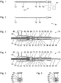
- FIG. 1 shows a schematic representation of a medical instrument 10 with a tool 13 at the distal end of a component 14.
- the tool 13 is in FIG. 1 exemplified as a tool for gripping, holding, squeezing, cutting or punching tissue between a fixed branch and a pivoting branch.
- the component 14 comprises a shaft 15 which may be straight or curved, rigid or elastic.
- the shaft 15 is particularly flexible and has a circular cross section with a diameter of 2 mm or less.
- the component 14 further comprises a transmission device 16 for transmitting a force.
- the transfer device 16 is disposed inside the shaft 15 and therefore actually not visible and in FIG. 1 indicated only by a dashed line.
- the proximal end of the shaft 15 has a significantly enlarged cross-section and is mechanically connected to a handling device 18.
- the handling device 18 has a manually movable part 19.
- the movable part 19 is coupled to the proximal end of the transmission device 16 such that a pivoting movement of the movable part 19 (in particular about a pivot axis orthogonal to the plane of the drawing FIG. 1 ) is associated with a movement, in particular a translation of the transfer device 16 relative to the shaft 15 relative to the other handling device 18.
- the distal end of the transmission device 16 is coupled to the movable part of the tool 13 such that movement of the transmission device 16 relative to the shaft 15 is associated with a pivoting movement of the movable part of the tool 13 relative to the rest of the tool 13.
- the component 14 can be separated non-destructively by the handling device 18, at the same time terminating the mechanical coupling of the proximal end of the transmission device 16 with the movable part 19 of the handling device 18.
- the component 14 is thus designed to form the medical instrument 10 together with the handling device 18.
- FIG. 2 shows a schematic representation of another component 14 for a medical instrument.
- Component 14 is similar in some features, properties, and functions to those of the FIG. 1 represented component.
- the proximal end of the shaft 15 can be detachably mechanically or non-destructively detachably mechanically connected to a handling device and the proximal end of the transfer device 16 can be detachably or permanently or non-destructively releasably coupled to a movable part of the handling device.
- FIG. 2 illustrated component 14 differs from the basis of the FIG. 1 represented component in particular by the fact that it has no tool at the distal end, but can only be connected to a tool 13 and coupled.
- the tool 13 is therefore indicated in dashed lines.
- the distal end of the shaft 15 of the component 14 can be provided and designed for permanent or non-destructively releasable or non-destructive releasable mechanical connection with a fixed part of the tool 13.
- the distal end of the transmission device 16 can be provided and designed for permanent or non-destructive releasable or destructive releasable mechanical coupling with a movable part of the tool 13.
- FIG. 3 shows a schematic representation of a section through a proximal end of a component 14 for forming a medical instrument.
- component 14 is similar in some - especially in the non-based FIGS. 3 to 5 - Characteristics, properties and functions according to the FIGS. 1 and 2 illustrated components.
- Component 14 shown comprises a transmission device (see reference 16 from the Figures 1 and 2 ) from distal (in FIG. 3 : left) to proximal (in FIG. 3 : Right) a wire 20 as a long thin portion of the transfer device, a first rod member 30 and a second rod member 40.
- component 14 comprises the shaft (see reference numeral 15 from the Figures 1 and 2 distal distal to proximal, a long thin shaft tube 50, a first sleeve member 60, a second sleeve member 70, and a third sleeve member 80.
- the proximal end of the shaft tube 50, the first sleeve member 60, and the distal end of the second sleeve member 70 are also of a terminal member 90 surrounded.
- the wire 20 has the shape of a long thin cylinder, in particular a circular cylinder.
- the wire 20 is provided and configured to transmit a force to a tool at the distal end of the component 14.
- the wire 20 is in particular made of surgical steel, spring steel or another metal.
- the wire may be made of plastic or contain a plastic.
- the proximal end 23 of the wire 20 is disposed in a first longitudinal bore 32 at the distal end of the first rod member 30 and mechanically rigidly connected thereto, for example, by welding, soldering, gluing or other material, force and / or positive manner.
- the first rod component 30 has at its proximal end a second longitudinal bore 34, in which a pin 43 is arranged at the distal end of the second rod component.
- the pin 43 at the distal end of the second rod component is mechanically rigidly connected to the second longitudinal bore 34 at the proximal end of the first rod component 30, for example by a screw connection between corresponding internal and external threads and / or in other ways.
- the second rod member 40 has at its proximal end a coupling ball 49 for releasable mechanical coupling with a movable part 19 of a handling device 18 (see. FIG. 1 ) on.
- the first rod component 30 also has a collar 35.
- the collar is at the in FIG. 3 shown at or near the proximal end of the first rod member 30.
- the collar 35 projects radially outward and surrounds the rest of the first rod member 30 annularly.
- a proximally oriented, flat and annular stop surface 36 and a distally oriented, flat and annular stop surface 37 are provided.
- the shaft tube 50 has a channel 52.
- the cross section of the channel 52 in the shaft tube 50 and the cross section of the wire 20 are chosen so that the wire 20 play and especially low friction in the channel 52 in the shaft tube 50 is guided.
- the shaft tube 50 has, for example, an annular cross-section and an outer diameter of 2 mm or less.
- the wire 20 has, for example, a circular cross-section and an outer diameter of a few tenths of a millimeter.
- the first sleeve component 60 has a substantially circular-cylindrical channel in which the proximal end 56 of the shaft tube 50 is arranged, and which is narrowed by a radially inwardly projecting collar 66 at the proximal end of the first sleeve component 60.
- the proximal end 56 of the shaft tube 50 abuts the collar 66 on a distally oriented, annular surface.
- the collar 66 narrows the channel enclosed by the first sleeve member 60 to a cross-section approximately equal to or greater than the cross-section of the channel 52 in the shaft tube 50.
- the wire 20 can also be moved relative to the first sleeve member 60 friction.
- the second sleeve member 70 encloses a channel 73 extending from the distal end to the proximal end of the second sleeve member 70.
- the cross section of the channel 73 in the second sleeve component 70 and the cross section of the first rod component 30 are selected such that the first rod component 30 is guided play and friction in the channel 73 in the second sleeve component 70.
- the channel 73 in the second sleeve member 70 is expanded in place by a radially outwardly extending groove in which an O-ring 74 is disposed.
- the groove, the O-ring 74 and the outer contour of the cross section of the first rod member 30 are selected the O-ring 74 bears against the outer lateral surface of the first rod component 30 at all times.
- the O-ring 74 may thus prevent or at least hinder passage of a fluid from distal to proximal. Further, the O-ring 74 may brake movement of the transmission 20, 30, 40 relative to the shaft 50, 60, 70, 80.
- the cross-section of the channel 73 in the second sleeve member 70 distal of the groove is greater than proximal of the groove.
- the cross-section of the channel 73 in the second sleeve member 70 is stepped near the distal end of the second sleeve member 70 to receive the first sleeve member 60 and to positively define the position of the first sleeve member 60 relative to the second sleeve member 70.
- the first sleeve component 60 is joined in the distal end of the channel 73 in the second sleeve component 70, in particular by means of a screw connection and / or in another form-fitting, force-fitting and / or material-locking manner.
- the third sleeve component 80 has a channel 83, in which above all the second rod component 40 is arranged.
- the cross section of the channel 83 in the third sleeve member 80 and the outer contour of the cross section of the second rod member 40 are selected so that the second rod member 40 is play and especially low friction in the channel 83 in the third sleeve member 80 out.
- the proximal end of the second sleeve member 70 and the distal end of the third sleeve member 80 are rigidly connected together.
- both the proximal end of the second sleeve member 70 and the distal end of the third sleeve member 80 are each tubular but of different diameters.
- the tubular proximal end of the second sleeve component 70 is inserted in the tubular distal end of the third sleeve component 80 and is connected to it in a positive, force and / or material fit.
- a distally stepped extension of the channel 83 in the third sleeve member 80 forms an annular recess 85 in the form of a projecting from the channel 83 in the third sleeve member 80 radially outwardly flat groove.
- the collar 35 is arranged on the first rod component 30.
- the cross section of the recess 85 and the outer contour of the collar 35 on the first rod member are chosen so that the collar 35 can be moved in the recess 85 friction.
- the distally oriented, annular and planar portion of the surface of the recess 85 forms a distally oriented abutment surface 86.
- Mechanical contact between the proximally oriented abutment surface 36 on the collar 35 on the first rod member 30 and the distally oriented abutment surface 86 in the recess 85 limits movement of the transfer device 20, 30, 40 relative to the shaft 50, 60, 70, 80 proximally.
- the proximally oriented annular and planar edge surface of the second sleeve member 70 forms the distal edge of the recess 85 and a proximally oriented abutment surface of the shaft 50, 60, 70, 80.
- connection component 90 has a flushing connection 95, which corresponds in particular to the Luer-Lock system.
- the purge port 95 is aligned with a purge port 59 in the stem tube 50 and allows for supply of a purge fluid into the gap between the wire 20 and the stem tube 50 for cleaning the component.
- FIG. 4 shows a further schematic representation of a section through the proximal end of the basis of the FIG. 3 represented component.
- the cutting plane of the FIG. 4 corresponds to the cutting plane of FIG. 3 ,
- FIG. 3 illustrates a situation or configuration in which the proximally-oriented abutment surface 36 abuts the collar 35 on the transfer device 20, 30, 40 on the distally-oriented abutment surface 86 on the shaft 50, 60, 70, 80.
- the FIG. 4 illustrated position of the transfer device 20, 30, 40 relative to the shaft 50, 60, 70, 80 is therefore the extremely proximal reachable position.
- a in the FIGS. 3 and 4 not shown tool at the distal end of the component 14 has one or two movable branches or jaw parts and is provided for gripping, holding, squeezing, cutting or punching, the jaw parts of the tool lie in the in FIG. 4 shown situation against each other and are pressed against each other.
- the component 14, in particular the positions of the proximally oriented abutment surface 36 on the collar 35 on the transfer device 20, 30, 40 and the distally oriented abutment surface 86 on the shaft 50, 60, 70, 80 and the elastic properties of the wire 20 are chosen so that at the in FIG. 4 shown situation, the wire 20 is only elastic, but not plastically deformed and also the shaft tube 50 and the tool are not destroyed or damaged by the forces acting thereby. This is especially true even if the tool is blocked in the fully open state, for example, by a hard or non-yielding object between the jaws.
- FIG. 5 shows a representation of another section through the basis of the FIGS. 3 and 4 illustrated component.
- the cutting plane of the FIG. 5 is orthogonal to the section plane of the FIGS. 3 and 4 and to the longitudinal and symmetry axis of the transmission device 20, 30, 40.
- the sectional plane of the FIG. 5 cuts the recess 85 and lies proximal of the collar 35 on the transmission device 20, 30, 40th FIG. 5 therefore shows a situation similar to that in FIG. 3 shown.
- FIG. 6 shows a schematic representation of a section through another component, the basis of the FIGS. 3 to 5 represented component 14 in some features, properties and functions similar.
- the cutting plane of the FIG. 6 corresponds to the cutting plane of FIG. 5 .
- Particular features, properties and functions are described below, in which the in FIG. 6 shown component is different from the component shown with reference to the figures 3 to 5.
- a longitudinal section through the in FIG. 6 shown component, as in the FIGS. 3 and 4 shown would be different from those in the FIGS. 3 and 4 shown sections do not differ. Therefore, below on the FIGS. 3 and 4 Referenced.
- the channel 30, 40 in the shaft 50, 60, 70, 80 widening recess, but one or more niche-shaped recesses 85.
- two recesses 85 are symmetrical to each other.
- the recesses 85 niche extend the channel 73, 83 in the shaft 50, 60, 70, 80, in which the transmission device 20, 30, 40 is arranged.
- the third sleeve component 80 has in the in FIG. 6 shown component in particular the same shape as in the reference to the FIGS. 3 to 5 represented component.
- the second sleeve component 70 has no annular proximal edge surface 78, but a stepped edge surface.
- the proximal edge of the second sleeve component 70 abuts in particular on the distally oriented annular abutment surface 86 on the third sleeve component 80, but is interrupted by two opposing slots which form the recesses 85.
- the distal ends of these slots form proximally oriented abutment surfaces 78 (see FIG. FIG. 3 ).
- the transmission device 20, 30, 40 no annular collar, but two opposing projections or lugs or pins 35.
- the lugs 35 are arranged in the recesses 85.
- FIG. 7 shows a schematic representation of a section through another component 14, which in some features, properties and functions based on the FIGS. 3 to 6 represented components corresponds.
- cutting plane corresponds the cutting plane of the FIGS. 3 and 4 .
- particular features, properties and functions of the component 14 are described, in which they differ from those on the basis of FIG FIGS. 3 to 6 distinguished components.
- component 14 may have an annular collar 35 on the transmission means 20, 30, 40 in an annular recess 85 in the shaft 50, 60, 70, 80, similar to those with reference to FIGS. 3 to 5 illustrated component.
- the in FIG. 7 shown component 14 one or more lugs on the transmission device 20, 30, 40, which are arranged in each case an associated recess 85 in the shaft 50, 60, 70, 80, similar to the component shown with reference to FIG 6
- component 14 differs from the basis of the FIGS. 3 to 6 in particular, characterized in that the first sleeve member 60 has no inwardly projecting collar at the proximal end.
- the channel 65 in the first sleeve member 60 is rather cylindrical throughout, in particular circular cylindrical. This allows production of the component 14, as determined by the FIGS. 8 to 13 is shown.
- FIG. 8 shows a schematic representation of a section through parts of the component 14 shown with reference to FIG. 7 during its production.
- the cutting plane of the FIG. 8 corresponds to the cutting planes of the FIGS. 3, 4 and 7 ,
- FIG. 12 shows a situation during the fabrication of the component where the wire 20 is already disposed in the channel 52 in the steerer tube 50.
- the proximal end 56 of the shaft tube 50 is inserted into the channel 65 in the first sleeve member 60.
- the shaft tube 50 is not yet rigidly connected to the first sleeve member 60, but may, as in the following with reference to FIGS. 10 to 12 described relative to the first sleeve member 60 are moved.
- the first sleeve component 60 has an external thread 67, which is provided and designed for positive and non-positive joining with a corresponding internal thread 76 at the distal end of the second sleeve component 70.
- FIG. 9 shows a further schematic representation of a section through the in FIG. 8 shown parts.
- the cutting plane of the FIG. 9 corresponds to the cutting planes of the FIGS. 3, 4 . 7 and 8 ,
- first sleeve member 60 by a screw connection between its external thread 67 (see. FIG. 8 ) is connected to the internal thread 76 on the second sleeve component 70 with the distal end of the second sleeve component 70.
- first sleeve component 60 and the second sleeve component 70 may be connected to one another in a different manner in terms of form, force and / or material fit.
- FIG. 10 shows a further schematic representation of a section through the in the FIGS. 8 and 9 shown parts.
- the cutting plane of the FIG. 10 corresponds to the cutting planes of the FIGS. 3, 4 and 7 to 9 ,
- the unit of the first sleeve member 60 and the second sleeve member 70 is displaced distally relative to the wire 20 and the shaft tube 50 such that the proximal end 23 of the wire 20 and optionally also as in FIG FIG. 10 indicated proximal end 56 of shaft tube 50 project proximally out of channel 73 in second sleeve component 70.
- FIG. 11 shows a further schematic representation of a section through parts of the basis of the FIG. 7 illustrated component 14 during their production.
- the cutting plane of the FIG. 11 corresponds to the cutting planes of the FIGS. 3, 4 and 7 to 10 ,
- the proximal end 23 of the wire 20 protruding from the second sleeve member 70 is inserted into the first longitudinal bore 32 at the distal end of the first rod member 30.
- a transverse bore 33 is provided in the first rod component 30 in the region of the first longitudinal bore 32 in order to enable or simplify a materially joining of the proximal end 23 of the wire 20 to the distal end of the first rod component 30.
- the proximal end 23 of the wire 20 is laser welded in the region of the transverse bore 33 joined to the first rod member 30 cohesively.
- the proximal end 23 of the wire 20 and the first rod component 30 can be connected to each other in a form-fitting, force-fitting and / or material-locking manner in a different manner.
- a transverse bore 33 in the first rod member 30, as in the FIGS. 7 and 11 can also be seen in the basis of the FIGS. 3 to 6 be provided components shown.
- FIG. 12 shows a further schematic representation of a section through the in FIG. 11 shown parts.
- the cutting plane of the FIG. 12 corresponds to the cutting planes of the FIGS. 3, 4 and 7 to 11 ,
- position of the unit of the first sleeve member 60 and the second sleeve member 70 relative to the proximal end 56 of the shaft tube 50 corresponds to the final or provided for the finished component position.
- the proximal end 56 of the shaft tube 50 is mechanically rigidly connected to the first sleeve member 60, for example by a circumferential laser weld or other form, force and / or material-locking manner.
- FIG. 13 shows a further schematic representation of a section through parts of the basis of the FIG. 7 illustrated component 14 during their production.
- the cutting plane of the FIG. 13 corresponds to the cutting planes of the FIGS. 3, 4 and 7 to 12 ,
- the third sleeve member 80 is attached in the intended manner to the second sleeve member 70 and may be connected to this form, force and / or material fit or be.
- connection member 90 must be slipped over the shaft tube 50, the first sleeve member 60 and the distal end of the second sleeve member 70 and joined with this form, force and / or material fit.
- FIG. 14 shows a schematic representation of a section through the proximal end of another component 14, which in some features, properties and functions based on the FIGS. 3 to 13 resembles shown components.
- the cutting plane of the FIG. 14 corresponds to the cutting planes of the FIGS. 3, 4 and 7 to 13 ,
- particular features and properties of the component 14 are described, in which they differ from those on the basis of FIG FIGS. 3 to 13 distinguished components.
- shown component 14 differs from the basis of the FIGS. 3 to 13 represented components in particular by the fact that only one rod member 30 is provided, the functions of both rod members 30, 40 of the basis of FIGS. 3 to 13 united components.
- the rod component 30 comprises in particular at its distal end a longitudinal bore 32, in which the proximal end 23 of the wire 20 is arranged and fixed, and at its proximal end a coupling ball 49 for releasable mechanical coupling with a movable part 19 of a handling device 18 (see. FIG. 1 ).
- a single rod member 30 may be provided instead of two interconnected rod components, which, as in the in FIG. 14 shown component 14 combines all the functions of the rod components in it.
- FIG. 14 shown component 14 differs from the basis of the FIGS. 3 to 13 shown components further characterized in that neither an annular collar nor one or more lugs are provided on the rod member 30. Rather, a pin 38 is provided in a corresponding transverse bore in the rod member 30. Both ends of the pin 38 are opposite to the outer contour of the rod member 30 and project into each an elongated recess 85 in the shaft 50, 60, 70, 80 into it. Proximally-oriented abutment surfaces 36 and distally-oriented abutment surfaces 37 of the transfer device 20, 30, 40 are formed by corresponding portions of the surfaces of the ends of the pin 38.
- the recesses 85 are formed by slots in the second sleeve member 70 which terminate outwardly through a tubular portion of the third sleeve member 80 become. Edge regions of the slots 85 forming the recesses in the second sleeve component 70 form the proximally oriented abutment surface 78 and the distally oriented abutment surface 86.
- FIG. 15 shows a schematic representation of a section through parts of the component shown with reference to FIG. 14.
- the cutting plane of the FIG. 15 corresponds to the cutting planes of the FIGS. 3, 4 and 7 to 14 ,
- FIG. 15 a situation is shown in which the first sleeve member 60 may already be mechanically rigidly connected to the proximal end 56 of the shaft tube 50. Further, the proximal end 23 of the wire 20 is already mechanically rigidly connected to the distal end of the rod member 30, namely, joined into the longitudinal bore 32 at the distal end of the rod member 30. The proximal end of the rod member 30 is already partially inserted into the channel 73 in the second sleeve member 70. In the second sleeve component 70 are opposing slots which form the recesses 85, and the proximal and distal ends of which form the distally oriented abutment surfaces 86 and the proximally oriented abutment surfaces 78, recognizable.
- the second sleeve member 70 may be displaced distally relative to the other illustrated components and connected to the first sleeve member 60, for example by screwing between an external thread 67 on the first sleeve member 60 and an internal thread 76 on the second sleeve member 70.
- FIG. 16 shows a further schematic representation of a section through parts of the basis of the FIG. 14 illustrated component 14 during their production.
- the cutting plane of the FIG. 16 corresponds to the cutting planes of the FIGS. 3, 4 and 7 to 15 ,
- FIG. 16 The situation shown differs from that in FIG. 15 shown situation in that the first sleeve member 60 is rigidly and in particular permanently mechanically rigidly connected to the second sleeve member 70.
- the pin 38 is already partially inserted through one of the two slots on the second sleeve component 70, which form the two recesses 85, into a corresponding transverse bore 39 in the rod component 30.
- the pin 38 relative to the rod member 30 its intended and in FIG. 14 has reached the position shown in FIG. 16 already shown slipped over the proximal end of the rod member 30 shown third sleeve member 80 attached to the proximal end of the second sleeve member 70 and mechanically rigidly and in particular permanently connected thereto.
- connection component 90 can be slipped over the first sleeve component 60 and the distal end of the second sleeve component 70 from the distal side before or after it.
- a mechanically rigid connection between the connecting member 90 and the second sleeve member 70 is in the reference to the FIGS. 3 to 16 represented by engagement of an inwardly projecting collar at the proximal end of the connection member 90 in a corresponding circumferential groove on the second sleeve member 70 each formed.
- the connection component 90 in all with reference to the FIGS. 3 to 16 shown components 14 are positively, positively and / or materially joined to the shaft tube 50 and / or with the second sleeve member 70.
- FIG. 17 shows a schematic flow diagram of a method for producing a component for a medical instrument, in particular one of the basis of the FIGS. 3 to 16 illustrated components.
- the method is also suitable for producing a component with features, properties and functions that are based on the FIGS. 1 to 16 differ. Nevertheless, reference numerals from the FIGS. 1 to 16 used as an example to facilitate understanding.
- a distal end of a transmission device 16, 20, 30, 40 is coupled to a movable part of a tool 13.
- the tool 13 is intended in particular for gripping, holding, squeezing, cutting or punching and has, for example, a stationary sector or a stationary jaw part and a sector which can be pivoted relative to the stationary industry.
- the pivoting branch can be coupled directly by a hinge or indirectly via a connecting rod to the distal end of the transfer device 16, 20, 30, 40.
- the pivotable industry may otherwise be coupled to the distal end of the transfer direction 16, 20, 30, 40 such that translation of the transfer device 16, 20, 30, 40 is associated with pivotal movement of the pivotable industry.
- a second step 102 the tool 13 is connected to the distal end of the shaft 15, 50, 60, 70, 80.
- the tool is in particular permanently or non-destructively detachably connected to the distal end of the shaft 15, 50, 60, 70, 80.
- a proximal end 56 of a shaft tube 50 is moved to a mounting position (see FIG. Figures 10 . 11 ) is inserted into the first component 60, 70 of the shaft 15, 50, 60, 70, 80 relative to a first component 60, 70 of a shaft 15, 50, 60, 70, 80 to be manufactured as part of the component to be manufactured.
- the mounting position of the proximal end 56 of the shaft tube 50 (see. Figures 10 . 11 ) is located proximally of the intended position for the finished component (see. FIG. 7 ) of the proximal end 56 of the shaft tube 50 relative to the first member 60, 70 of the shaft 15, 50, 60, 70, 80.
- the mounting position of the proximal end 56 of the shaft tube 50 may be proximal (see Figures 10, 11) or distal the proximal end of the first member 60, 70 of the shaft 15, 50, 60, 70, 80 are located.
- a proximal end 23 of a first component 20 of a transmission device 16, 20, 30, 40 is moved from distally to a mounting position (cf. Figures 10 . 11 ) passed through the first member 60, 70 of the shaft 15, 50, 60, 70, 80.
- the mounting position of the proximal end 23 of the first member 20 relative to the first member 60, 70 of the shaft 15, 50, 60, 70, 80 is proximal to its finished one Component 14 provided position (see FIG. FIG. 7 ).
- the mounting position of the proximal end 23 of the first component 20 of the transmission device 160, 20, 30, 40 lies in particular proximally of the proximal end of the first component 60, 70 of the shaft 15, 50, 60, 70, 80.
- the first step 101, the second step 102, the third step 103 and the fourth step 104 are executed in particular in the stated order. Alternatively, these steps may be performed in a different order, wherein the first step 101 and the second step 102 are executed in particular before the third step 103 and / or before the fourth step 104.
- the third step 103 and the fourth step 104 may be executed simultaneously.
- the first step 101, the second step 102 and the third step 103 are each optional and may be omitted.
- a fifth step 105 the proximal end 23 of the first component 20 of the transmission device 16, 20, 30, 40 is mechanically connected to a second component 30, 40 of the transmission device 16, 20, 30, 40.
- the mechanical connection produced at the fifth step 105 is in particular a permanent or non-destructive releasable connection.
- the second component 30, 40 of the transmission device 16, 20, 30, 40 and the first component 50, 60, 70 of the shaft 15, 50, 60, 70, 80 are in particular designed such that a movement of the second component 30, 40 of the Transmission means 16, 20, 30, 40 relative to the first member 50, 60, 70 of the shaft 15, 50, 60, 70, 80 by mechanical contact corresponding stop surfaces 37, 78 is limited distally.
- proximal end 23 of the first component 20 of the transfer device 16, 20, 30, 40 starting from the mounting position of the proximal end 23 of the first member 20 is distal to a position provided for the finished component relative to the first Component 60, 70 of the shaft 15, 50, 60, 70, 80 moves.
- a seventh step 107 the proximal end 56 of the shaft tube 50 is moved distally relative to the first component of the shaft 15, 50, 60, 70, 80, to the position provided for use of the component 14.
- the sixth step 106 and the seventh step 107 are executed in particular simultaneously or in any order, but both after the fourth step 104 and the fifth step 105.
- the proximal end 56 of the shaft tube 50 is connected to the first component 60, 70 of the shaft 15, 50, 60, 70, 80.
- the eighth step 108 is carried out in particular after the seventh step 107, ie at the position of the proximal end 56 of the shaft tube 50 provided for the finished component 14 relative to the first component 60, 70 of the shaft 15, 50, 60, 70, 80.
Landscapes
- Health & Medical Sciences (AREA)
- Surgery (AREA)
- Life Sciences & Earth Sciences (AREA)
- Medical Informatics (AREA)
- Animal Behavior & Ethology (AREA)
- Engineering & Computer Science (AREA)
- Biomedical Technology (AREA)
- Heart & Thoracic Surgery (AREA)
- Veterinary Medicine (AREA)
- Molecular Biology (AREA)
- Nuclear Medicine, Radiotherapy & Molecular Imaging (AREA)
- General Health & Medical Sciences (AREA)
- Public Health (AREA)
- Oral & Maxillofacial Surgery (AREA)
- Pathology (AREA)
- Ophthalmology & Optometry (AREA)
- Surgical Instruments (AREA)
Abstract
Eine Komponente (14) für ein medizinisches Instrument umfasst einen Schaft (15), eine Übertragungseinrichtung (16), die in dem Schaft (15) bewegbar ist, zum Übertragen einer Kraft von einer mit dem proximalen Ende der Komponente (14) gekoppelten Handhabungseinrichtung (18) zu einem Werkzeug (14) an dem distalen Ende der Komponente (14), eine Anschlagfläche (86) an dem Schaft (15) und eine Anschlagfläche (36) an der Übertragungseinrichtung (16). Die Anschlagfläche (86) des Schafts (15) und die Anschlagfläche (36) der Übertragungseinrichtung (16) sind so angeordnet, dass ein mechanischer Kontakt zwischen der Anschlagfläche (36) der Übertragungseinrichtung (16) und der Anschlagfläche (86) des Schafts (15) eine Bewegung der Übertragungseinrichtung (16) relativ zu dem Schaft (15) nach proximal begrenzt ist.A component (14) for a medical instrument comprises a shaft (15), a transmission device (16) which is movable in the shaft (15), for transmitting a force from a handling device (14) coupled to the proximal end of the component (14). 18) to a tool (14) at the distal end of the component (14), a stop surface (86) on the shaft (15) and a stop surface (36) on the transfer device (16). The stop surface (86) of the shaft (15) and the abutment surface (36) of the transmission device (16) are arranged such that a mechanical contact between the abutment surface (36) of the transmission device (16) and the abutment surface (86) of the shaft (15 ) a movement of the transfer device (16) relative to the shaft (15) is limited proximally.
Description
Die vorliegende Erfindung ist auf eine Komponente für ein medizinisches Instrument und auf ein medizinisches Instrument bezogen. Die vorliegende Erfindung ist insbesondere auf Maßnahmen bezogen, die unter bestimmten Umständen eine Zerstörung eines medizinischen Instruments durch unsachgemäße Verwendung oder Handhabung verhindern können.The present invention relates to a component for a medical instrument and to a medical instrument. The present invention is particularly related to measures that, under certain circumstances, may prevent destruction of a medical instrument due to improper use or handling.
In
In
In
In
Eine Aufgabe der vorliegenden Erfindung besteht darin, eine verbesserte Komponente für ein medizinisches Instrument, ein verbessertes medizinisches Instrument und ein verbessertes Verfahren zum Herstellen einer Komponente für ein medizinisches Instrument zu schaffen.An object of the present invention is to provide an improved medical instrument component, an improved medical instrument, and an improved method of manufacturing a medical instrument component.
Diese Aufgabe wird durch die Gegenstände der unabhängigen Ansprüche gelöst.This object is solved by the subject matters of the independent claims.
Weiterbildungen sind in den abhängigen Ansprüchen angegeben.Further developments are specified in the dependent claims.
Eine Komponente für ein medizinisches Instrument umfasst einen Schaft, eine Übertragungseinrichtung, die in dem Schaft bewegbar ist, zum Übertragen einer Kraft von einer mit dem proximalen Ende der Komponente gekoppelten Handhabungseinrichtung zu einem Werkzeug an dem distalen Ende der Komponente, eine Anschlagfläche an dem Schaft und eine Anschlagfläche an der Übertragungseinrichtung, wobei die Anschlagfläche des Schafts und die Anschlagfläche der Übertragungseinrichtung so angeordnet sind, dass ein mechanischer Kontakt zwischen der Anschlagfläche und der Übertragungseinrichtung und der Anschlagfläche des Schafts eine Bewegung der Übertragungseinrichtung relativ zu dem Schaft nach proximal begrenzt.A component for a medical instrument comprises a shaft, a transmission device that is movable in the shaft, for transmitting a force from a handling device coupled to the proximal end of the component to a tool at the distal end of the component, a stop surface on the shaft and an abutment surface on the transfer device, the abutment surface of the shaft and the abutment surface of the transfer device being arranged such that mechanical contact between the abutment surface and the transfer device and the abutment surface of the shaft limit proximal movement of the transfer device relative to the shaft.
Die Komponente ist vorgesehen und ausgebildet, um mit einer oder mehreren weiteren Komponenten so mechanisch verbunden und / oder gekoppelt zu werden, dass ein medizinisches Instrument gebildet wird. Die Komponente ist insbesondere eine Komponente für ein mikroinvasives medizinisches Instrument, wobei der Schaft einen Durchmesser von wenigen Millimetern oder weniger und eine Länge von einigen Zentimetern oder wenigen oder einigen Dezimetern aufweist. Der Schaft kann beispielsweise dafür vorgesehen und ausgebildet sein, um in einen Arbeitskanal eines Endoskops eingeführt zu werden.The component is provided and adapted to be mechanically connected and / or coupled to one or more other components to form a medical instrument. The component is in particular a component for a micro-invasive medical instrument, wherein the shaft has a diameter of a few millimeters or less and a length of a few centimeters or a few or a few decimeters. For example, the shaft may be provided and configured to be inserted into a working channel of an endoscope.
Das proximale Ende des Schafts ist insbesondere zur zerstörungsfrei lösbaren oder zur dauerhaften bzw. nicht zerstörungsfrei lösbaren mechanischen Verbindung mit einer Handhabungseinrichtung vorgesehen und ausgebildet. Das proximale Ende der Übertragungseinrichtung ist insbesondere zur zerstörungsfrei lösbaren oder dauerhaften bzw. nicht zerstörungsfrei lösbaren mechanischen Kopplung mit einem manuell bewegbaren Teil einer Handhabungseinrichtung vorgesehen und ausgebildet.The proximal end of the shaft is provided and designed in particular for non-destructively detachable or permanent or non-destructive releasable mechanical connection with a handling device. The proximal end of the transmission device is provided and designed in particular for non-destructively detachable or permanent or non-destructive releasable mechanical coupling with a manually movable part of a handling device.
Die Komponente kann an ihrem distalen Ende ein Werkzeug aufweisen, das mit dem distalen Ende des Schafts insbesondere starr verbunden ist, und das einen bewegbaren Teil (beispielsweise eine schwenkbare Branche oder ein schwenkbares Maulteil) aufweist. Dabei ist der bewegbare Teil des Werkzeugs derart unmittelbar oder mittelbar mit dem distalen Ende der Übertragungseinrichtung mechanisch gekoppelt, dass eine Bewegung der Übertragungseinrichtung relativ zu dem Schaft mit einer Bewegung des bewegbaren Teils des Werkzeugs relativ zu einem anderen Teil des Werkzeugs einhergeht. Das Werkzeug kann mit dem distalen Ende des Schafts und mit dem distalen Ende der Übertragungseinrichtung zerstörungsfrei lösbar oder dauerhaft bzw. nicht zerstörungsfrei lösbar mechanisch verbunden und gekoppelt sein.The component may have at its distal end a tool which is in particular rigidly connected to the distal end of the shaft and which has a movable part (for example a pivoting branch or a pivotable jaw part). In this case, the movable part of the tool is mechanically or indirectly coupled directly or indirectly to the distal end of the transmission device in such a way that a movement of the transmission device relative to the shaft is accompanied by a movement of the movable part of the tool relative to another part of the tool. The tool can with the distal end of the shaft and with the distal end of the transmission device non-destructive releasably or permanently or not destructive releasably mechanically connected and coupled.
Alternativ kann die Komponente kein Werkzeug aufweisen, jedoch zur zerstörungsfrei lösbaren oder zur dauerhaften bzw. nicht zerstörungsfrei lösbaren mechanischen Verbindung und Kopplung eines Werkzeugs mit dem distalen Ende des Schafts und mit dem distalen Ende der Übertragungseinrichtung vorgesehen und ausgebildet sein.Alternatively, the component may have no tool, but may be provided and designed for non-destructively releasable or permanent or nondestructive releasable mechanical connection and coupling of a tool to the distal end of the shaft and to the distal end of the transmission.
Die Übertragungseinrichtung ist insbesondere in Richtung parallel zur Längsachse des Schafts relativ zu dem Schaft bewegbar. Die Übertragungseinrichtung ist insbesondere zum Übertragen einer Zugkraft von einem mit dem proximalen Ende der Übertragungseinrichtung gekoppelten bewegbaren Teil einer Handhabungseinrichtung zu einem mit dem distalen Ende der Übertragungseinrichtung gekoppelten bewegbaren Teil eines Werkzeugs vorgesehen und ausgebildet. Alternativ oder zusätzlich kann die Übertragungseinrichtung zum Übertragen einer Schubkraft von einem mit dem proximalen Ende der Übertragungseinrichtung gekoppelten bewegbaren Teil einer Handhabungseinrichtung zu einem mit dem distalen Ende der Übertragungseinrichtung gekoppelten bewegbaren Teil eines Werkzeugs vorgesehen und ausgebildet sein.The transmission device is movable in particular in the direction parallel to the longitudinal axis of the shaft relative to the shaft. The transmission device is provided and designed in particular for transmitting a tensile force from a movable part of a handling device coupled to the proximal end of the transmission device to a movable part of a tool coupled to the distal end of the transmission device. Alternatively or additionally, the transmission device may be provided and configured to transmit a thrust force from a movable part of a handling device coupled to the proximal end of the transmission device to a movable part of a tool coupled to the distal end of the transmission device.
Das distale Ende der Übertragungseinrichtung ist insbesondere mit einem bewegbaren Teil eines Werkzeugs derart koppelbar oder derart gekoppelt, dass eine Bewegung der Übertragungseinrichtung nach proximal mit der vorgesehenen Wirkbewegung des bewegbaren Teils des Werkzeugs einhergeht. In diesem Fall wird die für die Wirkbewegung des bewegbaren Teils des Werkzeugs erforderliche Kraft durch eine Zugkraft bzw. Zugspannung in der Übertragungseinrichtung übertragen. Die Wirkbewegung des bewegbaren Teils eines Werkzeugs ist die Bewegung, bei der das Werkzeug die vorgesehene Wirkung entfaltet. Bei einer Zange oder einem anderen Werkzeug zum Greifen, Halten, Quetschen, Stanzen oder Schneiden ist dies in der Regel die schließende Bewegung, bei der zwei (in manchen Fällen mehr) Maulteile bzw. Branchen aufeinander zu bewegt werden. In anderen Fällen kann die Wirkbewegung eine Bewegung sein, bei der Maulteile bzw. Branchen voneinander wegbewegt werden, beispielsweise bei einem Werkzeug zum Spreizen oder Weiten eines Gefäßes oder eines anderen Hohlraums.The distal end of the transmission device is in particular coupled or coupled to a movable part of a tool in such a way that a movement of the transmission device is associated proximally with the intended operative movement of the movable part of the tool. In this case, the force required for the effective movement of the movable part of the tool is transmitted by a tensile force in the transmission device. The active movement of the movable part of a tool is the movement in which the tool unfolds the intended effect. With a pair of pliers or other gripping, holding, squeezing, punching or cutting tools, this is typically the closing motion where two (in some cases more) jaws or branches are moved towards each other. In other cases, the active movement may be a movement in which jaws or industries Move away from each other, for example, in a tool for spreading or widening a vessel or other cavity.
Alternativ zu einer Anordnung der Anschlagfläche des Schafts und der Anschlagfläche der Übertragungseinrichtung derart, dass ein mechanischer Kontakt zwischen der Anschlagfläche der Übertragungseinrichtung und der Anschlagfläche des Schafts eine Bewegung der Übertragungseinrichtung relativ zu dem Schaft nach proximal begrenzt, können die Anschlagfläche des Schafts und die Anschlagfläche der Übertragungseinrichtung derart angeordnet sein, dass ein mechanischer Kontakt zwischen der Anschlagfläche der Übertragungseinrichtung und der Anschlagfläche des Schafts eine Bewegung der Übertragungseinrichtung relativ zu dem Schaft nach distal begrenzt.Alternatively to an arrangement of the abutment surface of the shaft and the abutment surface of the transmission device such that a mechanical contact between the abutment surface of the transmission device and the abutment surface of the shaft limits movement of the transmission device proximally relative to the shaft, the abutment surface of the shaft and the abutment surface of the Transmission means may be arranged such that a mechanical contact between the abutment surface of the transmission device and the abutment surface of the shaft delimits a movement of the transmission device distally relative to the shaft.
Bei einer Komponente, wie sie hier beschrieben ist, sind insbesondere die Anschlagfläche des Schafts nach distal und die Anschlagfläche der Übertragungseinrichtung nach proximal orientiert.In the case of a component as described here, in particular the abutment surface of the shaft is oriented distally and the abutment surface of the transmission device is oriented proximally.
Bei einer Komponente, wie sie hier beschrieben ist, sind insbesondere die Bewegung des distalen Endes der Übertragungseinrichtung relativ zu dem distalen Ende des Schafts nach proximal so begrenzt und die Anschlagfläche des Schafts und die Anschlagfläche der Übertragungseinrichtung so angeordnet, dass ein mechanischer Kontakt zwischen der Anschlagfläche der Übertragungseinrichtung und der Anschlagfläche des Schafts eine elastische Verformung der Übertragungseinrichtung durch eine von der Übertragungseinrichtung übertragene Kraft auf einen vorbestimmten Maximalwert begrenzt, wobei der vorbestimmte Maximalwert der elastischen Verformung und elastische Eigenschaften der Übertragungseinrichtung so gewählt sind, dass bei der Kraft, die bei dem vorbestimmten Maximalwert der elastischen Verformung der Übertragungseinrichtung vorliegt, eine Zerstörung oder Schädigung des Schafts, der Übertragungseinrichtung und eines mit dem distalen Ende des Schafts verbundenen und mit dem distalen Ende der Übertragungseinrichtung gekoppelten Werkzeugs ausgeschlossen ist.In particular, in a component as described herein, the movement of the distal end of the transfer device relative to the distal end of the shaft is proximally limited and the abutment surface of the shaft and abutment surface of the transfer device are arranged to provide mechanical contact between the abutment surface the transmission means and the abutment surface of the shaft delimits an elastic deformation of the transmission means by a force transmitted from the transmission means to a predetermined maximum value, wherein the predetermined maximum value of the elastic deformation and elastic properties of the transmission means are selected such that at the force corresponding to the predetermined Maximum value of the elastic deformation of the transmission device is present, a destruction or damage to the shaft, the transmission device and one connected to the distal end of the shaft and with the dis talen end of the transfer device coupled tool is excluded.
Die Bewegung des distalen Endes der Übertragungseinrichtung relativ zu dem distalen Ende des Schafts ist insbesondere durch ein Werkzeug, das mit dem distalen Ende des Schafts mechanisch verbunden und mit dem distalen Ende der Übertragungsrichtung mechanisch gekoppelt ist, begrenzt. Wenn die Komponente kein Werkzeug am distalen Ende umfasst, sondern zur mechanischen Verbindung und Kopplung mit einem Werkzeug vorgesehen und ausgebildet ist, ist die Bewegung des distalen Endes der Übertragungseinrichtung relativ zu dem distalen Ende des Schafts insbesondere nur dann nach proximal begrenzt oder nur dann in der Weise, die für die hier beschriebene Begrenzung der übertragenen Kraft auf den vorbestimmten Maximalwert erforderlich ist, begrenzt, wenn das distale Ende des Schafts mit dem für die Komponente vorgesehenen Werkzeug oder mit einem von mehreren für die Komponente vorgesehenen Werkzeugen in der vorgesehenen Weise verbunden und ein oder mehrere bewegbare Teile des Werkzeugs in der vorgesehenen Weise mit dem distalen Ende der Übertragungseinrichtung mechanisch gekoppelt sind.The movement of the distal end of the transfer device relative to the distal end of the shaft is in particular by a tool which is connected to the distal end of the shaft mechanically connected and mechanically coupled to the distal end of the transmission direction limited. If the component does not comprise a tool at the distal end, but is provided and designed for mechanical connection and coupling with a tool, the movement of the distal end of the transmission relative to the distal end of the shaft is limited to proximal only or only in the The manner required for the limitation of the transmitted force to the predetermined maximum value described herein is limited when the distal end of the shaft is connected to the tool provided for the component or to one of a plurality of tools provided for the component in the intended manner or a plurality of movable parts of the tool are mechanically coupled in the intended manner with the distal end of the transmission device.
Bei einer Komponente, wie sie hier beschrieben ist, sind die Anschlagfläche des Schafts und die Anschlagfläche der Übertragungseinrichtung insbesondere so angeordnet, dass ein mechanischer Kontakt zwischen der Anschlagfläche der Übertragungseinrichtung und der Anschlagfläche des Schafts bei der vorgesehenen Verwendung eine elastische Verformung der Übertragungseinrichtung durch eine von der Übertragungseinrichtung übertragene Kraft auf einen vorbestimmten Maximalwert begrenzt, wobei der vorbestimmte Maximalwert der elastischen Verformung und elastische Eigenschaften der Übertragungseinrichtung so gewählt sind, dass bei der Kraft, die bei dem vorbestimmten Maximalwert der elastischen Verformung der Übertragungseinrichtung vorliegt, eine Zerstörung oder Schädigung des Schafts, der Übertragungseinrichtung und eines mit dem distalen Ende des Schafts verbundenen und mit dem distalen Ende der Übertragungseinrichtung gekoppelten Werkzeugs ausgeschlossen ist.In a component as described here, the abutment surface of the shaft and the abutment surface of the transmission device are arranged in particular such that a mechanical contact between the abutment surface of the transmission device and the abutment surface of the shaft in the intended use elastic deformation of the transmission device by one of the force transmitted to the transmission means is limited to a predetermined maximum value, wherein the predetermined maximum value of the elastic deformation and elastic properties of the transmission means are chosen such that at the force which exists at the predetermined maximum value of the elastic deformation of the transmission means, destruction or damage of the shaft, the transfer device and a tool connected to the distal end of the shaft and coupled to the distal end of the transfer device is excluded.
Auch eine plastische Verformung der Übertragungseinrichtung, des Schafts oder eines mit dem distalen Ende des Schafts und dem distalen Ende der Übertragungseinrichtung gekoppelten Werkzeugs ist eine Schädigung der Übertragungseinrichtung, des Schafts bzw. des Werkzeugs. Ein Ausschluss einer Zerstörung oder Schädigung des Schafts, der Übertragungseinrichtung und eines mit dem distalen Ende des Schafts und dem distalen Ende der Übertragungseinrichtung gekoppelten Werkzeugs bedeutet somit auch, dass die Übertragungseinrichtung, der Schaft und das Werkzeug jeweils lediglich elastisch und nicht plastisch verformt werden.Also, plastic deformation of the transfer device, the shaft or a tool coupled to the distal end of the shaft and the distal end of the transfer device is damage to the transfer device, the shaft or the tool. Exclusion of destruction or damage to the shaft, the transfer device and a tool coupled to the distal end of the shaft and the distal end of the transfer device thus also means that the transfer device, the shank and the tool are deformed only elastically and not plastically.
Bei einer Komponente, wie sie hier beschrieben ist, ist eine Zerstörung oder Schädigung des Schafts, der Übertragungseinrichtung und eines mit dem distalen Ende des Schafts gekoppelten Werkzeugs insbesondere auch dann ausgeschlossen, wenn das Werkzeug in einem ganz geöffneten oder in einem ganz geschlossenen oder in einem beliebigen Zustand blockiert ist.In the case of a component as described here, destruction or damage to the shaft, the transmission device and a tool coupled to the distal end of the shaft are also excluded, in particular when the tool is in a fully opened or in a completely closed position or in one any state is blocked.
Ein mit dem distalen Ende des Schafts verbundenes und mit dem distalen Ende der Übertragungseinrichtung gekoppeltes Werkzeug zum Schneiden, Greifen, Halten, Quetschen oder Stanzen kann beispielsweise durch einen harten oder bei der erzeugbaren Kraft nicht nachgebenden Gegenstand in seiner ganz geöffneten Konfiguration blockiert werden. Wenn die Übertragungseinrichtung mit dem bewegbaren Teil des Werkzeugs derart gekoppelt ist, dass zum Schließen des Werkzeugs eine durch die Übertragungseinrichtung zu übertragende Zugkraft erforderlich ist, ist die Übertragungseinrichtung dann maximal verformt, nämlich gedehnt, wenn das Werkzeug im ganz geöffneten Zustand blockiert ist und die Anschlagfläche der Übertragungseinrichtung an der Anschlagfläche des Schafts anliegt. Die Anschlagfläche der Übertragungseinrichtung und die Anschlagfläche des Schafts sind so positioniert und die elastischen Eigenschaften der Übertragungseinrichtung sind so gewählt, dass auch in diesem Fall der Schaft, die Übertragungseinrichtung und ein mit dem distalen Ende des Schafts gekoppeltes Werkzeug nicht geschädigt oder zerstört werden.A cutting, grasping, holding, squeezing or punching tool connected to the distal end of the shaft and coupled to the distal end of the transfer device may be blocked, for example, by a hard or non-yielding force in its fully open configuration. If the transmission device is coupled to the movable part of the tool in such a way that a tensile force to be transmitted by the transmission device is required to close the tool, the transmission device is then deformed to a maximum, namely stretched when the tool is blocked in the fully open state and the stop surface the transmission device bears against the abutment surface of the shaft. The abutment surface of the transfer device and the abutment surface of the shaft are positioned in this way and the elastic properties of the transfer device are selected so that in this case the shaft, the transfer device and a tool coupled to the distal end of the shaft are not damaged or destroyed.
Bei einer Komponente, wie sie hier beschrieben ist, sind insbesondere die Anschlagfläche des Schafts nahe dem proximalen Ende des Schafts und die Anschlagfläche der Übertragungseinrichtung nahe dem proximalen Ende der Übertragungseinrichtung angeordnet.In a component as described here, in particular the abutment surface of the shaft near the proximal end of the shaft and the abutment surface of the transmission device are arranged near the proximal end of the transmission device.
Der Abstand der Anschlagfläche des Schafts von dem proximalen Ende des Schafts beträgt insbesondere nicht mehr als ein Fünftel oder nicht mehr als ein Zehntel der Länge des Schafts. Der Abstand der Anschlagfläche der Übertragungseinrichtung von dem proximalen Ende der Übertragungseinrichtung beträgt insbesondere nicht mehr als ein Fünftel oder nicht mehr als ein Zehntel der Länge der Übertragungseinrichtung.The distance of the abutment surface of the shaft from the proximal end of the shaft is in particular not more than one fifth or not more than one tenth of the length of the shaft. The distance of the stop surface of the transmission device from the proximal end of the transmission device is in particular not more than one fifth or not more than one tenth of the length of the transmission device.
Bei einer Komponente, wie sie hier beschrieben ist, sind die Anschlagfläche des Schafts und die Anschlagfläche der Übertragungseinrichtung insbesondere in einem proximalen Bereich des Schafts, in dem der Schaft einen vergrößerten Durchmesser oder einen vergrößerten Querschnitt aufweist, angeordnet.In a component as described here, the abutment surface of the shaft and the abutment surface of the transmission device are arranged in particular in a proximal region of the shaft, in which the shaft has an enlarged diameter or an enlarged cross section.
Bei einer Komponente, wie sie hier beschrieben ist, sind die Anschlagfläche des Schafts und die Anschlagfläche der Übertragungseinrichtung insbesondere in einem Bereich des Schafts, der zur Aufnahme in einer Handhabungseinrichtung vorgesehen ist, angeordnet.In a component as described here, the abutment surface of the shaft and the abutment surface of the transmission device are arranged in particular in a region of the shaft which is intended to be received in a handling device.
Der Schaft weist insbesondere einen langen und dünnen rohrförmigen Abschnitt und einen im Vergleich zu dem rohrförmigen Abschnitt wesentlich dickeren proximalen Abschnitt auf. Der lange und dünne rohrförmige Abschnitt des Schafts erstreckt sich in der Regel über mindestens zwei Drittel oder mindestens vier Fünftel oder mindestens neun Zehntel der Länge des Schafts und hat einen Durchmesser von wenigen Millimetern oder weniger. Durchmesser und Querschnitt des proximalen Abschnitts des Schafts sind in der Regel deutlich größer als Durchmesser und Querschnitt des langen und dünnen rohrförmigen Abschnitts. In dem proximalen Abschnitt steht mehr Bauraum für die Anschlagfläche des Schafts und für die Anschlagfläche der Übertragungseinrichtung zur Verfügung.In particular, the stem has a long and thin tubular portion and a much thicker proximal portion than the tubular portion. The long and thin tubular portion of the shaft typically extends over at least two thirds, or at least four fifths or at least nine tenths of the length of the shaft, and has a diameter of a few millimeters or less. Diameter and cross-section of the proximal portion of the shaft are typically significantly larger than the diameter and cross-section of the long and thin tubular portion. In the proximal portion more space is available for the abutment surface of the shaft and for the abutment surface of the transmission device.
Bei einer Komponente, wie sie hier beschrieben ist, weist die Übertragungseinrichtung insbesondere in einem Abschnitt distal der Anschlagfläche der Übertragungseinrichtung ihre minimale Querschnittsfläche auf, wobei alle Querschnittsflächen der Übertragungseinrichtung proximal der Anschlagfläche der Übertragungseinrichtung größer sind als die minimale Querschnittsfläche der Übertragungseinrichtung.In a component as described here, the transfer device has its minimum cross-sectional area, in particular in a section distal to the abutment surface of the transfer device, wherein all cross-sectional areas of the transfer device proximal to the abutment surface of the transfer device are greater than the minimum cross-sectional area of the transfer device.
Die Querschnittsfläche der Übertragungseinrichtung ist insbesondere proximal der Anschlagfläche der Übertragungseinrichtung durchgehend wesentlich größer als distal der Anschlagfläche der Übertragungseinrichtung. Die Querschnittsfläche der Übertragungseinrichtung ist beispielsweise proximal der Anschlagfläche der Übertragungseinrichtung durchgehend mindestens um einen Faktor 5 oder mindestens um einen Faktor 10 oder mindestens um einen Faktor 20 größer als distal der Anschlagfläche der Übertragungseinrichtung. Die Übertragungseinrichtung weist insbesondere distal der Anschlagfläche der Übertragungseinrichtung weitgehend einen konstanten kreisförmigen Querschnitt mit einem Durchmesser von weniger als 1 mm auf. Proximal der Anschlagfläche der Übertragungseinrichtung weist die Übertragungseinrichtung insbesondere durchgehend einen kreisförmigen oder anderen Querschnitt mit einer Querschnittsfläche von mehreren Quadratmillimetern auf.The cross-sectional area of the transmission device is, in particular, substantially greater than the stop surface of the transmission device, in particular, proximally of the stop surface of the transmission device. The cross-sectional area of the transmission device is, for example, continuously greater than the stop surface of the transmission device, at least by a factor of 5 or at least a factor of 10 or at least a factor of 20, proximally of the stop surface of the transmission device. The transmission device has in particular distally the stop surface of the Transfer device largely a constant circular cross-section with a diameter of less than 1 mm. Proximal of the abutment surface of the transmission device, the transmission device in particular has a continuous circular or other cross-section with a cross-sectional area of several square millimeters.
Eine Ausgestaltung der Übertragungseinrichtung derart, dass ihre Querschnittsfläche proximal der Anschlagfläche der Übertragungseinrichtung deutlich größer ist als distal, ermöglicht eine große Robustheit der Übertragungseinrichtung proximal der Anschlagfläche der Übertragungseinrichtung und deshalb ein geringes Risiko einer Zerstörung oder Schädigung durch eine zu große Kraft.An embodiment of the transfer device such that its cross-sectional area proximal to the abutment surface of the transfer device is significantly larger than distally allows a great robustness of the transfer device proximal to the abutment surface of the transfer device and therefore a low risk of destruction or damage due to excessive force.
Bei einer Komponente, wie sie hier beschrieben ist, weist die Übertragungseinrichtung insbesondere in einem Abschnitt distal der Anschlagfläche der Übertragungseinrichtung ihre minimale Zugfestigkeit auf, wobei die Zugfestigkeit der Übertragungseinrichtung proximal der Anschlagfläche der Übertragungseinrichtung durchgehend größer ist als die minimale Zugfestigkeit der Übertragungseinrichtung.In a component as described here, the transmission device has its minimum tensile strength, in particular in a section distal to the abutment surface of the transmission device, wherein the tensile strength of the transmission device proximal to the abutment surface of the transmission device is continuously greater than the minimum tensile strength of the transmission device.
Die Zugfestigkeit der Übertragungseinrichtung ist proximal der Anschlagfläche der Übertragungseinrichtung insbesondere wesentlich größer als die minimale Zugfestigkeit der Übertragungseinrichtung. Die Zugfestigkeit der Übertragungseinrichtung ist proximal der Anschlagfläche der Übertragungseinrichtung beispielsweise mindestens um einen Faktor 5 oder um einen Faktor 10 oder um einen Faktor 20 größer als die minimale Zugfestigkeit der Übertragungseinrichtung.The tensile strength of the transmission device is, in particular, substantially greater than the minimum tensile strength of the transmission device proximal to the stop surface of the transmission device. The tensile strength of the transfer device is proximal to the abutment surface of the transfer device, for example at least a factor of 5 or by a factor of 10 or by a factor of 20 greater than the minimum tensile strength of the transmission device.
Bei einer Komponente, wie sie hier beschrieben ist, ist die Übertragungseinrichtung insbesondere distal der Anschlagfläche der Übertragungseinrichtung bis zu einer ersten Maximalkraft elastisch verformbar, wobei die Übertragungseinrichtung proximal der Anschlagfläche der Übertragungseinrichtung bis zu einer zweiten Maximalkraft elastisch verformbar ist, und wobei die zweite Maximalkraft größer ist als die erste Maximalkraft. Die Maximalkraft, bis zu der die Übertragungseinrichtung an einem bestimmten Punkt elastisch verformbar ist, ist die größte Kraft, bei der die Übertragungseinrichtung an dem bestimmten Punkt noch nicht plastisch verformt wird. Die zweite Maximalkraft ist insbesondere deutlich größer als die erste Maximalkraft. Die zweite Maximalkraft ist insbesondere mindestens um einen Faktor 2 oder mindestens um einen Faktor 5 oder mindestens um einen Faktor 10 oder mindestens um einen Faktor 20 oder mindestens um einen Faktor 50 größer als die erste Maximalkraft.In the case of a component as described here, the transmission device is elastically deformable in particular distally of the abutment surface of the transmission device up to a first maximum force, wherein the transmission device is elastically deformable proximally of the abutment surface of the transmission device up to a second maximum force, and wherein the second maximum force is greater is considered the first maximum force. The maximum force to which the transfer device is elastically deformable at a certain point is the greatest force at which the transfer device is not yet plastically deformed at the particular point. The second maximum force is in particular significantly greater than the first maximum force. The second maximum force is in particular at least a factor of 2 or at least a factor of 5 or at least a factor of 10 or at least a factor of 20 or at least a factor of 50 greater than the first maximum force.
Durch Ausgestaltung und Anordnung der Anschlagfläche der Übertragungseinrichtung und der Anschlagfläche des Schafts und Wahl elastischer Eigenschaften der Übertragungseinrichtung kann eine Zerstörung oder Schädigung der Übertragungseinrichtung sowie des Schafts und eines Werkzeugs am distalen Ende der Komponente verhindert werden. Eine proximal der Anschlagfläche der Übertragungseinrichtung wesentlich größere mechanische Robustheit der Übertragungseinrichtung kann auch das Risiko einer Zerstörung oder Schädigung der Übertragungseinrichtung proximal der Anschlagfläche der Übertragungseinrichtung deutlich reduzieren.By design and arrangement of the abutment surface of the transmission device and the abutment surface of the shaft and the choice of elastic properties of the transmission device destruction or damage to the transmission device and the shaft and a tool at the distal end of the component can be prevented. A substantially greater mechanical robustness of the transmission device proximal to the stop surface of the transmission device can also significantly reduce the risk of destruction or damage to the transmission device proximal to the stop surface of the transmission device.
Bei einer Komponente, wie sie hier beschrieben ist, kann die Übertragungseinrichtung insbesondere weder nach proximal noch nach distal aus dem Schaft entnommen werden ohne den Schaft zu zerlegen.In the case of a component as described here, the transmission device can in particular be removed from the shaft neither proximally nor distally without disassembling the shaft.
Eine Komponente, wie sie hier beschrieben ist, umfasst insbesondere ferner eine weitere Anschlagfläche an dem Schaft und eine weitere Anschlagfläche an der Übertragungseinrichtung, wobei die weitere Anschlagfläche des Schafts und die weitere Anschlagfläche der Übertragungseinrichtung so angeordnet sind, dass ein mechanischer Kontakt zwischen der weiteren Anschlagfläche der Übertragungseinrichtung und der weiteren Anschlagfläche des Schafts eine Bewegung der Übertragungseinrichtung relativ zu dem Schaft nach distal begrenzt.In particular, a component as described here further comprises a further stop surface on the shaft and a further stop surface on the transmission device, the further stop surface of the shaft and the further stop surface of the transmission device being arranged such that a mechanical contact between the further stop surface the transmission device and the further stop surface of the shaft, a movement of the transmission device relative to the shaft distally limited.
Die weitere Anschlagfläche des Schafts ist insbesondere nahe dem proximalen Ende des Schafts und insbesondere nahe der Anschlagfläche des Schafts angeordnet. Die weitere Anschlagfläche der Übertragungseinrichtung ist insbesondere nahe dem proximalen Ende der Übertragungseinrichtung und insbesondere nahe der Anschlagfläche der Übertragungseinrichtung angeordnet. Insbesondere sind die weitere Anschlagfläche des Schafts nach proximal und die weitere Anschlagfläche der Übertragungseinrichtung nach distal orientiert.The further abutment surface of the shaft is arranged in particular near the proximal end of the shaft and in particular near the abutment surface of the shaft. The further stop surface of the transmission device is in particular near the proximal end the transmission device and in particular arranged near the stop surface of the transmission device. In particular, the further abutment surface of the shaft are oriented proximally and the further abutment surface of the transmission device is distally oriented.
Die Begrenzung der Bewegung der Übertragungseinrichtung relativ zu dem Schaft nach distal kann eine Überlastung, Schädigung oder Zerstörung der Übertragungseinrichtung, des Schafts oder eines Werkzeugs am distalen Ende der Komponente durch eine zu hohe durch die Übertragungseinrichtung übertragene Schubkraft verhindern. Insbesondere kann eine Stauchung der Übertragungseinrichtung distal der weiteren Anschlagfläche der Übertragungseinrichtung verhindert werden.Limiting the movement of the transfer device relative to the shaft distally may prevent overload, damage or destruction of the transfer device, shaft or tool at the distal end of the component by excessive thrust transmitted by the transfer device. In particular, a compression of the transmission device distal to the further stop surface of the transmission device can be prevented.
Bei einer Komponente, wie sie hier beschrieben ist, weist die Übertragungseinrichtung insbesondere einen nach außen ragenden Kragen auf, wobei der Schaft eine Nut, die einen Kanal, in dem die Übertragungseinrichtung angeordnet ist, erweitert, aufweist, wobei der Kragen der Übertragungseinrichtung in der Nut des Schafts angeordnet ist, wobei die Anschlagfläche des Schafts Teil der inneren Oberfläche der Nut ist, und wobei die Anschlagfläche der Übertragungseinrichtung Teil der Oberfläche des Kragens ist.In a component as described here, the transmission device has in particular an outwardly projecting collar, wherein the shaft has a groove which widens a channel in which the transmission device is arranged, the collar of the transmission device being in the groove the shaft is disposed, wherein the abutment surface of the shaft is part of the inner surface of the groove, and wherein the abutment surface of the transmission device is part of the surface of the collar.
Eine nach proximal orientierte Oberfläche des Kragens kann die Anschlagfläche der Übertragungseinrichtung, eine nach distal orientierte Oberfläche der Nut kann die Anschlagfläche des Schafts bilden. Eine nach distal orientierte Oberfläche an dem Kragen kann die weitere Anschlagfläche der Übertragungseinrichtung, eine nach proximal orientierte Fläche in der Nut kann die weitere Anschlagfläche des Schafts bilden, um eine Bewegung der Übertragungseinrichtung relativ zu dem Schaft nach distal zu begrenzen.A proximally oriented surface of the collar may form the abutment surface of the transfer device, a distally oriented surface of the groove may form the abutment surface of the shaft. A distally-oriented surface on the collar may define the further abutment surface of the transfer device, a proximally-oriented surface in the groove may form the further abutment surface of the shaft to distally limit movement of the transfer device relative to the shaft.
Der Kragen ist insbesondere ringförmig oder kreisringförmig. In diesem Fall bildet insbesondere ein ringförmiger oder kreisringförmiger Bereich der Oberfläche des Kragens die Anschlagfläche der Übertragungseinrichtung.The collar is in particular annular or circular. In this case, in particular an annular or annular region of the surface of the collar forms the abutment surface of the transmission device.
Die Nut ist insbesondere ringförmig oder kreisringförmig und erweitert den Kanal, in dem die Übertragungseinrichtung angeordnet ist, ringförmig. In diesem Fall bildet insbesondere ein ringförmiger oder kreisringförmiger Bereich der inneren Oberfläche der Nut die Anschlagfläche des Schafts.The groove is in particular annular or annular and widens the channel in which the transmission device is arranged, annular. In this case forms in particular an annular or annular portion of the inner surface of the groove the abutment surface of the shaft.
Bei einer Komponente, wie sie hier beschrieben ist, weist die Übertragungseinrichtung insbesondere einen Vorsprung, eine Nase, einen Steg, einen Zapfen oder einen anderen konvexen Bereich auf, wobei der Schaft eine Nut oder eine andere nischenförmige Ausnehmung, die von einem Kanal, in dem die Übertragungseinrichtung angeordnet ist, ausgeht, aufweist, wobei der Vorsprung oder die Nase oder der Steg oder der Zapfen oder der andere konvexe Bereich der Übertragungseinrichtung in der Nut oder der anderen nischenförmigen Ausnehmung des Schafts angeordnet ist, wobei die Anschlagfläche des Schafts Teil der inneren Oberfläche der Nut oder der anderen nischenförmigen Ausnehmung des Schafts ist, und wobei die Anschlagfläche der Übertragungseinrichtung Teil der Oberfläche des Vorsprungs oder der Nase oder des Stegs oder des Zapfens oder des anderen konvexen Bereichs ist.In a component as described here, the transmission device has in particular a projection, a nose, a web, a journal or another convex region, wherein the shaft has a groove or another recess in the form of a channel, in which the transmission means is arranged, emanates, wherein the projection or the nose or the web or the pin or the other convex portion of the transmission means in the groove or the other niche-shaped recess of the shaft is arranged, wherein the abutment surface of the shaft part of the inner surface the groove or the other niche-shaped recess of the shaft, and wherein the abutment surface of the transmission device is part of the surface of the projection or the nose or the web or the pin or the other convex portion.
Ferner können ein weiterer, nach proximal orientierter Teil der inneren Oberfläche der Nut oder der anderen nischenförmigen Ausnehmung des Schafts eine weitere Anschlagfläche des Schafts und ein weiterer, nach distal orientierter Teil der Oberfläche des Vorsprungs oder der Nase oder des Stegs oder des Zapfens oder des anderen konvexen Bereichs eine weitere Anschlagfläche der Übertragungseinrichtung bilden, um eine Bewegung der Übertragungseinrichtung relativ zu dem Schaft nach distal zu begrenzen.Further, another proximal-oriented portion of the inner surface of the groove or other recess of the shaft may be another abutment surface of the stem and another distally oriented portion of the surface of the projection or nose or ridge or peg or other convex portion form a further abutment surface of the transfer device to limit a movement of the transfer device relative to the shaft to the distal.
Eine Komponente, wie sie hier beschrieben ist, umfasst insbesondere ferner ein Werkzeug an dem distalen Ende des Schafts, wobei das Werkzeug ein bewegbares Bauteil, das mit dem distalen Ende der Übertragungseinrichtung gekoppelt ist, aufweist.In particular, a component as described herein further includes a tool at the distal end of the shaft, the tool having a movable member coupled to the distal end of the transmission.
Das Werkzeug kann mit dem distalen Ende des Schafts zerstörungsfrei lösbar oder dauerhaft bzw. nicht zerstörungsfrei lösbar verbunden sein. Das Werkzeug ist insbesondere zum Greifen, Fassen, Halten, Quetschen, Schneiden oder Stanzen ausgebildet. Das bewegbare Bauteil ist insbesondere eine Branche oder ein Maulteil des Werkzeugs. Das bewegbare Bauteil ist insbesondere derart mit der Übertragungseinrichtung gekoppelt, dass eine lineare Translationsbewegung der Übertragungseinrichtung in Richtung parallel zu ihrer Längsachse mit einer Schwenkbewegung des bewegbaren Bauteils einhergeht.The tool may be non-destructively releasably or permanently or non-destructively releasably connected to the distal end of the shaft. The tool is designed in particular for gripping, grasping, holding, squeezing, cutting or punching. The movable component is in particular an industry or a jaw part of the tool. The movable component is in particular so coupled to the transmission device that a linear Translational movement of the transmission device in the direction parallel to its longitudinal axis is accompanied by a pivoting movement of the movable member.
Ein medizinisches Instrument umfasst eine Komponente, wie sie hier beschrieben ist, und eine Handhabungseinrichtung, die mit dem proximalen Ende des Schafts gekoppelt oder koppelbar ist.A medical instrument includes a component as described herein and a handling device that is coupled or coupleable to the proximal end of the shaft.
Ein Verfahren zum Herstellen einer Komponente für ein medizinisches Instrument umfasst einen Schritt des Hindurchführens eines proximalen Endes eines ersten Bauteils einer Übertragungseinrichtung von distal durch ein erstes Bauteil eines Schafts bis zu einer Montageposition, die proximal der für die fertiggestellte Komponente vorgesehenen Position relativ zu dem ersten Bauteil des Schafts liegt, einen Schritt des mechanischen Verbindens des proximalen Endes des ersten Bauteils der Übertragungseinrichtung mit einem zweiten Bauteil der Übertragungseinrichtung und einen Schritt des Bewegens des proximalen Endes des ersten Bauteils der Übertragungseinrichtung nach distal bis zu einer für die fertiggestellte Komponente vorgesehenen Position relativ zu dem ersten Bauteil des Schafts.A method of manufacturing a medical instrument component comprises a step of passing a proximal end of a first component of a transfer device distally through a first component of a shaft to a mounting position proximal to the position provided for the completed component relative to the first component of the shaft, a step of mechanically connecting the proximal end of the first component of the transfer device to a second component of the transfer device and a step of moving the proximal end of the first component of the transfer device distally to a position provided for the completed component relative to the first first component of the shaft.
Das Verfahren ist insbesondere zum Herstellen einer Komponente, wie sie hier beschrieben ist oder für eine andere Komponente mit hier beschriebenen Merkmalen, Eigenschaften und Funktionen geeignet. Die Schritte des Hindurchführens, des Verbindens und des Bewegens werden insbesondere in dieser Reihenfolge ausgeführt. Das proximale Ende des ersten Bauteils der Übertragungseinrichtung wird mit dem zweiten Bauteil der Übertragungseinrichtung insbesondere dauerhaft bzw. nicht zerstörungsfrei lösbar verbunden. Das zweite Bauteil der Übertragungseinrichtung, mit dem das proximale Ende des ersten Bauteils der Übertragungseinrichtung verbunden ist, und das erste Bauteil des Schafts sind insbesondere so ausgeführt, dass eine Bewegung des zweiten Bauteils der Übertragungseinrichtung relativ zu dem ersten Bauteil des Schafts durch mechanischen Kontakt korrespondierender Anschlagflächen nach distal begrenzt ist.The method is particularly suitable for producing a component as described herein or for another component having features, properties and functions described herein. The steps of passing, connecting and moving are executed in particular in this order. The proximal end of the first component of the transmission device is in particular permanently or non-destructively releasably connected to the second component of the transmission device. The second component of the transmission device, to which the proximal end of the first component of the transmission device is connected, and the first component of the shaft are in particular designed such that a movement of the second component of the transmission device relative to the first component of the shaft by mechanical contact corresponding stop surfaces is distally limited.
Ein Verfahren, wie es hier beschrieben ist, umfasst insbesondere ferner einen Schritt des Einführens eines proximalen Endes eines Schaftrohrs in das erste Bauteil des Schafts bis zu einer Montageposition, die proximal der für die fertiggestellte Komponente vorgesehenen Position relativ zu dem ersten Bauteil des Schafts liegt, vor dem Verbinden des proximalen Endes des ersten Bauteils der Übertragungseinrichtung mit dem zweiten Bauteil der Übertragungseinrichtung, einen Schritt des Bewegens des proximalen Endes des Schaftrohrs relativ zu dem ersten Bauteil des Schafts nach distal bis zu der für die Verwendung der Komponente vorgesehenen Position des Schaftrohrs relativ zu dem ersten Bauteil des Schafts nach dem Verbinden des proximalen Endes des ersten Bauteils der Übertragungseinrichtung mit dem zweiten Bauteil der Übertragungseinrichtung, und einen Schritt des mechanischen Verbindens des proximalen Endes des Schaftrohrs mit dem ersten Bauteil des Schafts an der für die fertiggestellte Komponente vorgesehenen Position relativ zu dem ersten Bauteil des Schafts.In particular, a method as described herein further includes a step of inserting a proximal end of a shaft tube into the first component of the shaft 1 to 3 to a mounting position that is proximal to the position provided for the completed component relative to the first component of the shaft, prior to connecting the proximal end of the first component of the transfer device to the second component of the transfer device, a step of moving the proximal end of the shaft tube relative to the first component of the shaft distally to the position of the shaft tube relative to the first component of the shaft intended for use of the component after connecting the proximal end of the first component of the transmission device to the second component of the transmission device, and a step of mechanical Connecting the proximal end of the shaft tube with the first component of the shaft at the position provided for the finished component relative to the first component of the shaft.
Das proximale Ende des Schaftrohrs wird mit dem ersten Bauteil des Schafts insbesondere dauerhaft bzw. nicht zerstörungsfrei lösbar verbunden.The proximal end of the shaft tube is in particular permanently or non-destructively releasably connected to the first component of the shaft.
Ein Verfahren, wie es hier beschrieben ist, umfasst insbesondere einen Schritt des Koppelns eines distalen Endes der Übertragungseinrichtung mit einem bewegbaren Teil eines Werkzeugs und einen Schritt des mechanischen Verbindens des Werkzeugs mit einem distalen Ende des Schafts.In particular, a method as described herein comprises a step of coupling a distal end of the transfer device to a movable part of a tool and a step of mechanically connecting the tool to a distal end of the shaft.
Bei einem Verfahren, wie es hier beschrieben ist, werden insbesondere zumindest entweder der Schritt des Koppelns des distalen Endes der Übertragungseinrichtung mit einem bewegbaren Teil des Werkzeugs oder der Schritt des mechanischen Verbindens des Werkzeugs mit dem distalen Ende des Schafts zumindest entweder vor dem Schritt des Einführens des proximalen Endes des Schaftrohrs in das erste Bauteil des Schafts oder vor dem Schritt des Hindurchführens des proximalen Endes des ersten Bauteils der Übertragungseinrichtung von distal durch das erste Bauteil des Schafts ausgeführt.In particular, in one method as described herein, at least one of the steps of coupling the distal end of the transfer device to a movable part of the tool, or mechanically connecting the tool to the distal end of the shaft, at least either prior to the step of inserting of the proximal end of the shaft tube into the first component of the shaft or before the step of passing the proximal end of the first component of the transmission device from distally through the first component of the shaft.
Nachfolgend werden Ausführungsformen anhand der beigefügten Figuren näher erläutert. Es zeigen:
- Figur 1
- eine schematische Darstellung eines medizinischen Instruments;
- Figur 2
- eine schematische Darstellung einer Komponente eines medizinischen Instruments;
- Figur 3
- eine schematische Darstellung eines Schnitts durch das proximale Ende einer Komponente eines medizinischen Instruments;
- Figur 4
- eine weitere schematische Darstellung eines Schnitts durch das proximale Ende der Komponente aus
Figur 3 ; - Figur 5
- eine schematische Darstellung eines weiteren Schnitts durch das proximale Ende der Komponente aus den
Figuren 3 und 4 ; - Figur 6
- eine schematische Darstellung eines Schnitts durch eine weitere Komponente eines medizinischen Instruments;
Figur 7- eine schematische Darstellung eines Schnitts durch das proximale Ende einer weiteren Komponente eines medizinischen Instruments;
- Figur 8
- eine schematische Darstellung eines Schnitts durch Teile der Komponente aus Figur 7;
- Figur 9
- eine weitere schematische Darstellung eines Schnitts durch die Teile aus
Figur 8 ; Figur 10- eine weitere schematische Darstellung eines Schnitts durch die Teile aus den Figuren 8 und 9;
- Figur 11
- eine schematische Darstellung eines Schnitts durch Teile der Komponente aus
den Figuren 7 ;bis 10 - Figur 12
- eine weitere schematische Darstellung eines Schnitts durch die Teile aus
Figur 11 ; Figur 13- eine weitere schematische Darstellung eines Schnitts durch Teile der Komponente aus
Figur 7 ; Figur 14- eine schematische Darstellung eines Schnitts durch das proximale Ende einer weiteren Komponente eines medizinischen Instruments;
Figur 15- eine weitere schematische Darstellung eines Schnitts durch Teile der Komponente aus
Figur 14 ; Figur 16- eine weitere schematische Darstellung eines Schnitts durch Teile der Komponente aus
Figur 14 ; - Figur 17
- ein schematisches Flussdiagramm eines Verfahrens zum Herstellen einer Komponente für ein medizinisches Instrument.
- FIG. 1
- a schematic representation of a medical instrument;
- FIG. 2
- a schematic representation of a component of a medical instrument;
- FIG. 3
- a schematic representation of a section through the proximal end of a component of a medical instrument;
- FIG. 4
- a further schematic representation of a section through the proximal end of the component
FIG. 3 ; - FIG. 5
- a schematic representation of a further section through the proximal end of the component of the
FIGS. 3 and 4 ; - FIG. 6
- a schematic representation of a section through another component of a medical instrument;
- FIG. 7
- a schematic representation of a section through the proximal end of another component of a medical instrument;
- FIG. 8
- a schematic representation of a section through parts of the component of Figure 7;
- FIG. 9
- a further schematic representation of a section through the parts
FIG. 8 ; - FIG. 10
- a further schematic representation of a section through the parts of Figures 8 and 9;
- FIG. 11
- a schematic representation of a section through parts of the component of the
FIGS. 7 to 10 ; - FIG. 12
- a further schematic representation of a section through the parts
FIG. 11 ; - FIG. 13
- a further schematic representation of a section through parts of the component
FIG. 7 ; - FIG. 14
- a schematic representation of a section through the proximal end of another component of a medical instrument;
- FIG. 15
- a further schematic representation of a section through parts of the component
FIG. 14 ; - FIG. 16
- a further schematic representation of a section through parts of the component
FIG. 14 ; - FIG. 17
- a schematic flow diagram of a method for manufacturing a component for a medical instrument.
Die Komponente 14 umfasst einen Schaft 15, der gerade oder gekrümmt, starr oder elastisch sein kann. Der Schaft 15 ist insbesondere flexibel und weist einen kreisförmigen Querschnitt mit einem Durchmesser von 2 mm oder weniger auf. Die Komponente 14 umfasst ferner eine Übertragungseinrichtung 16 zum Übertragen einer Kraft. Die Übertragungseinrichtung 16 ist im Inneren des Schafts 15 angeordnet und deshalb tatsächlich nicht sichtbar und in
Das proximale Ende des Schafts 15 weist einen deutlich vergrößerten Querschnitt auf und ist mit einer Handhabungseinrichtung 18 mechanisch verbunden. Die Handhabungseinrichtung 18 weist ein manuell bewegbares Teil 19 auf. Das bewegbare Teil 19 ist mit dem proximalen Ende der Übertragungseinrichtung 16 derart gekoppelt, dass eine Schwenkbewegung des bewegbaren Teils 19 (insbesondere um eine Schwenkachse orthogonal zur Zeichenebene der
Die Komponente 14 ist von der Handhabungseinrichtung 18 zerstörungsfrei trennbar, wobei gleichzeitig die mechanische Kopplung des proximalen Endes der Übertragungseinrichtung 16 mit dem bewegbaren Teil 19 der Handhabungseinrichtung 18 beendet wird. Die Komponente 14 ist also dazu ausgebildet, um zusammen mit der Handhabungseinrichtung 18 das medizinische Instrument 10 zu bilden.The
Die in
Bei der in
Der Draht 20 weist die Gestalt eines langen dünnen Zylinders, insbesondere eines Kreiszylinders auf. Der Draht 20 ist zur Übertragung einer Kraft zu einem Werkzeug am distalen Ende der Komponente 14 vorgesehen und ausgebildet. Der Draht 20 ist insbesondere aus chirurgischem Stahl, Federstahl oder einem anderen Metall gebildet. Alternativ kann der Draht aus Kunststoff gefertigt sein oder einen Kunststoff enthalten.The
Das proximale Ende 23 des Drahts 20 ist in einer ersten Längsbohrung 32 am distalen Ende des ersten Stabbauteils 30 angeordnet und mit diesem beispielsweise durch Schweißen, Löten, eine Klebung oder auf andere stoff-, kraft- und / oder formschlüssige Weise mechanisch starr verbunden. Das erste Stabbauteil 30 weist an seinem proximalen Ende eine zweite Längsbohrung 34 auf, in der ein Zapfen 43 am distalen Ende des zweiten Stabbauteils angeordnet ist. Der Zapfen 43 am distalen Ende des zweiten Stabbauteils ist mit der zweiten Längsbohrung 34 am proximalen Ende des ersten Stabbauteils 30 beispielsweise durch eine Schraubverbindung zwischen korrespondierenden Innen- und Außengewinden und / oder auf andere Weise mechanisch starr verbunden. Das zweite Stabbauteil 40 weist an seinem proximalen Ende eine Kopplungskugel 49 zur lösbaren mechanischen Kopplung mit einem bewegbaren Teil 19 einer Handhabungseinrichtung 18 (vgl.
Das erste Stabbauteil 30 weist ferner einen Kragen 35 auf. Der Kragen ist bei dem in
Das Schaftrohr 50 weist einen Kanal 52 auf. Der Querschnitt des Kanals 52 in dem Schaftrohr 50 und der Querschnitt des Drahts 20 sind so gewählt, dass der Draht 20 spiel- und vor allem reibungsarm in dem Kanal 52 in dem Schaftrohr 50 geführt ist. Das Schaftrohr 50 weist beispielsweise einen kreisringförmigen Querschnitt und einen Außendurchmesser von 2 mm oder weniger auf. Der Draht 20 weist beispielsweise einen kreisförmigen Querschnitt und einen Außendurchmesser von wenigen Zehntelmillimetern auf.The
Das erste Hülsenbauteil 60 weist einen im Wesentlichen kreiszylindrischen Kanal auf, in dem das proximale Ende 56 des Schaftrohrs 50 angeordnet ist, und der durch einen nach radial innen ragenden Kragen 66 am proximalen Ende des ersten Hülsenbauteils 60 verengt wird. Das proximale Ende 56 des Schaftrohrs 50 liegt an einer nach distal orientierten, kreisringförmigen Fläche an dem Kragen 66 an. Der Kragen 66 verengt den durch das erste Hülsenbauteil 60 umschlossenen Kanal auf einem Querschnitt, der näherungsweise dem Querschnitt des Kanals 52 in dem Schaftrohr 50 entspricht oder größer ist. Somit kann der Draht 20 auch relativ zu dem ersten Hülsenbauteil 60 reibungsarm bewegt werden.The
Das zweite Hülsenbauteil 70 umschließt einen Kanal 73, der sich vom distalen Ende bis zum proximalen Ende des zweiten Hülsenbauteils 70 erstreckt. Der Querschnitt des Kanals 73 in dem zweiten Hülsenbauteil 70 und der Querschnitt des ersten Stabbauteils 30 sind so gewählt, dass das erste Stabbauteil 30 in dem Kanal 73 in dem zweiten Hülsenbauteil 70 spiel- und reibungsarm geführt ist.The
Der Kanal 73 in dem zweiten Hülsenbauteil 70 ist an einem Ort durch eine nach radial außen sich erstreckende Nut, in der ein O-Ring 74 angeordnet ist, erweitert. Die Nut, der O-Ring 74 und die äußere Kontur des Querschnitts des ersten Stabbauteils 30 sind so gewählt, dass der O-Ring 74 an der äußeren Mantelfläche des ersten Stabbauteils 30 jederzeit anliegt. Der O-Ring 74 kann auf diese Weise einen Übertritt eines Fluids von distal nach proximal unterbinden oder zumindest behindern. Ferner kann der O-Ring 74 eine Bewegung der Übertragungseinrichtung 20, 30, 40 relativ zu dem Schaft 50, 60, 70, 80 bremsen. Um die Erzeugung der Nut für den O-Ring 74 zu vereinfachen, ist der Querschnitt des Kanals 73 in dem zweiten Hülsenbauteil 70 distal der Nut größer als proximal der Nut.The
Der Querschnitt des Kanals 73 in dem zweiten Hülsenbauteil 70 ist nahe dem distalen Ende des zweiten Hülsenbauteils 70 stufenförmig erweitert, um das erste Hülsenbauteil 60 aufzunehmen, und die Position des ersten Hülsenbauteils 60 relativ zu dem zweiten Hülsenbauteil 70 formschlüssig zu definieren. Das erste Hülsenbauteil 60 ist im distalen Ende des Kanals 73 in dem zweiten Hülsenbauteil 70 insbesondere mittels einer Schraubverbindung und / oder auf andere form-, kraft- und / oder stoffschlüssige Weise gefügt.The cross-section of the
Das dritte Hülsenbauteil 80 weist einen Kanal 83 auf, in dem vor allem das zweite Stabbauteil 40 angeordnet ist. Der Querschnitt des Kanals 83 in dem dritten Hülsenbauteil 80 und die äußere Kontur des Querschnitts des zweiten Stabbauteils 40 sind so gewählt, dass das zweite Stabbauteil 40 spiel- und vor allem reibungsarm in dem Kanal 83 in dem dritten Hülsenbauteil 80 geführt ist.The
Das proximale Ende des zweiten Hülsenbauteils 70 und das distale Ende des dritten Hülsenbauteils 80 sind starr miteinander verbunden. Bei dem dargestellten Beispiel sind sowohl das proximale Ende des zweiten Hülsenbauteils 70 als auch das distale Ende des dritten Hülsenbauteils 80 jeweils rohrförmig, jedoch mit unterschiedlichen Durchmessern ausgebildet. Das rohrförmige proximale Ende des zweiten Hülsenbauteils 70 steckt in dem rohrförmigen distalen Ende des dritten Hülsenbauteils 80 und ist mit diesem form-, kraft- und / oder stoffschlüssig gefügt.The proximal end of the
Eine nach distal stufenförmige Erweiterung des Kanals 83 in dem dritten Hülsenbauteil 80 bildet eine ringförmige Ausnehmung 85 in Gestalt einer von dem Kanal 83 in dem dritten Hülsenbauteil 80 aus nach radial außen ragenden, flachen Nut. In der Ausnehmung 85 ist der Kragen 35 an dem ersten Stabbauteil 30 angeordnet. Der Querschnitt der Ausnehmung 85 und die äußere Kontur des Kragens 35 an dem ersten Stabbauteil sind so gewählt, dass der Kragen 35 in der Ausnehmung 85 reibungsarm bewegt werden kann.A distally stepped extension of the
Der nach distal orientierte, ringförmige und ebene Bereich der Oberfläche der Ausnehmung 85 bildet eine nach distal orientierte Anschlagfläche 86. Mechanischer Kontakt zwischen der nach proximal orientierten Anschlagfläche 36 an dem Kragen 35 an dem ersten Stabbauteil 30 und der nach distal orientierten Anschlagfläche 86 in der Ausnehmung 85 begrenzt eine Bewegung der Übertragungseinrichtung 20, 30, 40 relativ zu dem Schaft 50, 60, 70, 80 nach proximal.The distally oriented, annular and planar portion of the surface of the
Die nach proximal orientierte ringförmige und ebene Randfläche des zweiten Hülsenbauteils 70 bildet den distalen Rand der Ausnehmung 85 und eine nach proximal orientierte Anschlagfläche des Schafts 50, 60, 70, 80. Mechanischer Kontakt zwischen der nach distal orientierten Anschlagfläche 37 an dem Kragen 35 an dem ersten Stabbauteil 30 und der nach proximal orientierten Anschlagfläche 78 an dem Schaft 50, 60, 70, 80 begrenzt eine Bewegung der Übertragungseinrichtung 20, 30, 40 relativ zu dem Schaft 50, 60, 70, 80 nach distal.The proximally oriented annular and planar edge surface of the
Das Anschlussbauteil 90 weist einen Spülanschluss 95 auf, der insbesondere dem Luer-Lock-System entspricht. Der Spülanschluss 95 fluchtet mit einer Spülöffnung 59 in dem Schaftrohr 50 und ermöglicht eine Zufuhr eines Spülfluids in den Zwischenraum zwischen dem Draht 20 und dem Schaftrohr 50 zur Reinigung der Komponente.The
In
Die Komponente 14, insbesondere die Positionen der nach proximal orientierten Anschlagfläche 36 an dem Kragen 35 an der Übertragungseinrichtung 20, 30, 40 und der nach distal orientierten Anschlagfläche 86 an dem Schaft 50, 60, 70, 80 sowie die elastischen Eigenschaften des Drahts 20 sind so gewählt, dass bei der in
In
Die in
Bei der in
Ähnlich wie bei der anhand der
Die in
Die in
In
Bei der in
Bei der in
Bei der in
Eine Querbohrung 33 in dem ersten Stabbauteil 30, wie sie in den
Bei der in
Bei der in
Auch bei den anhand der
Die in
Die Ausnehmungen 85 werden durch Schlitze in dem zweiten Hülsenbauteil 70 gebildet, die nach außen durch einen rohrförmigen Abschnitt des dritten Hülsenbauteils 80 abgeschlossen werden. Randbereiche der die Ausnehmungen 85 bildenden Schlitze in dem zweiten Hülsenbauteil 70 bilden die nach proximal orientierte Anschlagfläche 78 und die nach distal orientierte Anschlagfläche 86.The
Mechanischer Kontakt zwischen den nach proximal orientierten Anschlagflächen 36 an dem Stift 38 und den nach distal orientierten Anschlagflächen 86 an den proximalen Enden der Ausnehmungen 85 begrenzt die Bewegung der Übertragungseinrichtung 20, 30 relativ zu dem Schaft 50, 60, 70, 80 nach proximal. Mechanischer Kontakt zwischen den nach distal orientierten Anschlagflächen 37 an den Enden des Stifts 38 und den nach proximal orientierten Anschlagflächen 78 an den distalen Enden der Ausnehmungen 85 begrenzen die Bewegung der Übertragungseinrichtung 20, 30 relativ zu dem Schaft 50, 60, 70, 80 nach distal.Mechanical contact between the proximally oriented abutment surfaces 36 on the
In
Ausgehend von der in
Die in
Ferner kann bereits davor oder danach das Anschlussbauteil 90 von distal her über das erste Hülsenbauteil 60 und das distale Ende des zweiten Hülsenbauteils 70 gestülpt werden. Eine mechanisch starre Verbindung zwischen dem Anschlussbauteil 90 und dem zweiten Hülsenbauteil 70 wird bei den anhand der
Bei einem ersten Schritt 101 wird ein distales Ende einer Übertragungseinrichtung 16, 20, 30, 40 mit einem bewegbaren Teil eines Werkzeugs 13 gekoppelt. Das Werkzeug 13 ist insbesondere zum Greifen, Halten, Quetschen, Schneider oder Stanzen vorgesehen und weist beispielsweise eine feststehende Branche bzw. ein feststehendes Maulteil und eine relativ zu der feststehenden Branche schwenkbare Branche auf. Die schwenkbare Branche kann unmittelbar durch ein Gelenk oder mittelbar über einen Pleuel mit dem distalen Ende der Übertragungseinrichtung 16, 20, 30, 40 gekoppelt werden. Alternativ kann die schwenkbare Branche auf andere Weise derart mit dem distalen Ende der Übertragungsrichtung 16, 20, 30, 40 gekoppelt werden, dass eine Translation der Übertragungseinrichtung 16, 20, 30, 40 mit einer Schwenkbewegung der schwenkbaren Branche einhergeht.In a
Bei einem zweiten Schritt 102 wird das Werkzeug 13 mit dem distalen Ende des Schafts 15, 50, 60, 70, 80 verbunden. Bei dem zweiten Schritt 102 wird das Werkzeug insbesondere dauerhaft bzw. nicht zerstörungsfrei lösbar mit dem distalen Ende des Schafts 15, 50, 60, 70, 80 verbunden.In a
Bei einem dritten Schritt 103 wird ein proximales Ende 56 eines Schaftrohrs 50 bis zu einer Montageposition (vgl.
Bei einem vierten Schritt 104 wird ein proximales Ende 23 eines ersten Bauteils 20 einer Übertragungseinrichtung 16, 20, 30, 40 von distal her bis zu einer Montageposition (vgl.
Der erste Schritt 101, der zweite Schritt 102, der dritte Schritt 103 und der vierte Schritt 104 werden insbesondere in der angegebenen Reihenfolge ausgeführt. Alternativ können diese Schritte in einer anderen Reihenfolge ausgeführt werden, wobei der erste Schritt 101 und der zweite Schritt 102 insbesondere vor dem dritten Schritt 103 und / oder vor dem vierten Schritt 104 ausgeführt werden. Wenn der erste Schritt 101 und der zweite Schritt 102 vor dem dritten Schritt 103 und dem vierten Schritt 104 ausgeführt werden, können der dritte Schritt 103 und der vierte Schritt 104 gleichzeitig ausgeführt werden. Der erste Schritt 101, der zweite Schritt 102 und der dritte Schritt 103 sind jeweils optional und können entfallen.The
Bei einem fünften Schritt 105 wird das proximale Ende 23 des ersten Bauteils 20 der Übertragungseinrichtung 16, 20, 30, 40 mit einem zweiten Bauteil 30, 40 der Übertragungseinrichtung 16, 20, 30, 40 mechanisch verbunden. Die bei dem fünften Schritt 105 hergestellte mechanische Verbindung ist insbesondere eine dauerhafte bzw. nicht zerstörungsfrei lösbare Verbindung. Das zweite Bauteil 30, 40 der Übertragungseinrichtung 16, 20, 30, 40 und das erste Bauteil 50, 60, 70 des Schafts 15, 50, 60, 70, 80 sind insbesondere so ausgebildet, dass eine Bewegung des zweiten Bauteils 30, 40 der Übertragungseinrichtung 16, 20, 30, 40 relativ zu dem ersten Bauteil 50, 60, 70 des Schafts 15, 50, 60, 70, 80 durch mechanischen Kontakt korrespondierender Anschlagflächen 37, 78 nach distal begrenzt ist.In a
Bei einem sechsten Schritt 106 wird das proximale Ende 23 des ersten Bauteils 20 der Übertragungseinrichtung 16, 20, 30, 40 ausgehend von der Montageposition des proximalen Endes 23 des ersten Bauteils 20 nach distal bis zu einer für die fertiggestellte Komponente vorgesehenen Position relativ zu dem ersten Bauteil 60, 70 des Schafts 15, 50, 60, 70, 80 bewegt.In a
Bei einem siebten Schritt 107 wird das proximale Ende 56 des Schaftrohrs 50 relativ zu dem ersten Bauteil des Schafts 15, 50, 60, 70, 80 nach distal bis zu der für die Verwendung der Komponente 14 vorgesehenen Position bewegt.In a
Der sechste Schritt 106 und der siebte Schritt 107 werden insbesondere gleichzeitig oder in beliebiger Reihenfolge, jedoch beide nach dem vierten Schritt 104 und dem fünften Schritt 105 ausgeführt.The
Bei einem achten Schritt 108 wird das proximale Ende 56 des Schaftrohrs 50 mit dem ersten Bauteil 60, 70 des Schafts 15, 50, 60, 70, 80 verbunden. Der achte Schritt 108 wird insbesondere nach dem siebten Schritt 107, also bei der für die fertiggestellte Komponente 14 vorgesehenen Position des proximalen Endes 56 des Schaftrohrs 50 relativ zu dem ersten Bauteil 60, 70 des Schafts 15, 50, 60, 70, 80 ausgeführt.In an
- 1010
- medizinisches Instrumentmedical instrument
- 1313
- Werkzeug an dem distalen Ende des medizinischen Instruments 10Tool at the distal end of the medical instrument 10th
- 1414
-
Komponente des medizinischen Werkzeugs 10Component of the
medical tool 10 - 1515
-
Schaft des medizinischen Instruments 10 als Teil der Komponente 14Shaft of the
medical instrument 10 as part of thecomponent 14 - 1616
-
Übertragungseinrichtung des medizinischen Instruments 10 als Teil der Komponente 14Transmission device of the
medical instrument 10 as part of thecomponent 14 - 1818
- Handhabungseinrichtung an dem proximalen Ende des medizinischen Instruments 10Handling device at the proximal end of the medical instrument 10th
- 1919
-
manuell bewegbarer Teil der Handhabungseinrichtung 18manually movable part of the handling
device 18 - 2020
-
Draht, einen langen dünnen Abschnitt der Übertragungseinrichtung 16 bildend, zur Anordnung in dem Schaftrohr 50 vorgesehenWire, forming a long thin section of the
transfer device 16, is provided for placement in theshaft tube 50 - 2323
-
proximales Ende des Drahts 20proximal end of the
wire 20 - 3030
-
erstes Stabbauteil der Übertragungseinrichtung 16first rod component of the
transmission device 16 - 3232
-
erste Längsbohrung an dem distalen Ende des ersten Stabbauteils 30 zur Aufnahme des proximalen Endes 23 des Drahts 20first longitudinal bore at the distal end of the
first rod member 30 for receiving theproximal end 23 of thewire 20 - 3333
-
Querbohrung zur Herstellung einer Schweißverbindung des proximalen Endes 23 des Drahts 20 mit dem ersten Stabbauteil 30Transverse bore for producing a welded connection of the
proximal end 23 of thewire 20 with thefirst rod component 30 - 3434
-
zweite Längsbohrung an dem proximalen Ende des ersten Stabbauteils 30 zur Aufnahme des Zapfens 43 an dem distalen Endes des zweiten Stabbauteils 40second longitudinal bore at the proximal end of the
first rod member 30 for receiving thepin 43 at the distal end of thesecond rod member 40 - 3535
- Kragen oder Nase an dem ersten Stabbauteil 30Collar or nose on the first rod member 30th
- 3636
-
nach proximal orientierte Anschlagfläche der Übertragungseinrichtung 16, insb. Fläche an Kragen oder Nase 35 oder Stift 38proximally oriented abutment surface of the
transfer device 16, esp. Surface on collar ornose 35 or pin 38th - 3737
-
nach distal orientierte Anschlagfläche der Übertragungseinrichtung 16, insb. Fläche an Kragen oder Nase 35 oder Stift 38Distally oriented stop surface of the
transfer device 16, esp. Surface on collar ornose 35 or pin 38th - 3838
- Stiftpen
- 3939
-
Querbohrung in dem ersten Stabbauteil 30, zur Aufnahme des Stifts 38Transverse bore in the
first rod member 30, for receiving the pin 38th - 4040
-
zweites Stabbauteil der Übertragungseinrichtung 16second rod component of the
transmission device 16 - 4343
-
Zapfen an dem distalen Ende des zweiten Stabbauteils 40 zur mechanischen Verbindung mit dem ersten Stabbauteil 30Stud at the distal end of the
second rod member 40 for mechanical connection to the first rod member 30th - 4949
-
Kopplungskugel an dem proximalen Ende des zweiten Stabbauteils 40 zur Kopplung mit dem manuell bewegbaren Teil 19 der Handhabungseinrichtung 18Coupling ball at the proximal end of the
second rod member 40 for coupling with the manuallymovable part 19 of the handling device 18th - 5050
-
Schaftrohr des Schafts 15Shaft of the
shaft 15 - 5252
-
Kanal in dem Schaftrohr 50 zur Aufnahme des Drahts 20Channel in the
shaft tube 50 for receiving the wire 20th - 5656
-
proximales Ende des Schaftrohrs 50proximal end of the
shaft tube 50 - 5959
-
Spülöffnung in dem Schaftrohr 50Flushing opening in the
shaft tube 50 - 6060
-
erstes Hülsenbauteil des Schafts 15, das proximale Ende 56 des Schaftrohrs 50 mit dem zweiten Hülsenbauteil 70 verbindendfirst sleeve member of the
shaft 15, theproximal end 56 of theshaft tube 50 with thesecond sleeve member 70 connecting - 6565
-
Kanal in dem ersten Hülsenbauteil 60, zur Aufnahme des proximalen Endes 56 des Schaftrohrs 50Channel in the
first sleeve member 60, for receiving theproximal end 56 of the shaft tube 50th - 6666
- nach radial innen ragender Kragen an dem proximalen Ende des ersten Hülsenbauteils 60radially inwardly projecting collar at the proximal end of the first sleeve member 60th
- 6767
-
Außengewinde an dem ersten Hülsenbauteil 60 zur mechanischen Verbindung mit dem zweiten Hülsenbauteil 70External thread on the
first sleeve member 60 for mechanical connection with the second sleeve member 70th - 7070
- zweites Hülsenbauteil des Schafts 15second sleeve member of the shaft 15th
- 7373
-
Kanal in dem zweiten Hülsenbauteil 70, zur Aufnahme der Übertragungseinrichtung 16Channel in the
second sleeve member 70, for receiving the transfer device 16th - 7474
-
O-Ring in dem zweiten Hülsenbauteil 70O-ring in the
second sleeve member 70 - 7676
-
Innengewinde an dem distalen Ende des zweiten Hülsenbauteil 70 zur mechanischen Verbindung mit dem Außengewinde 67 an dem ersten Hülsenbauteil 60Internal thread at the distal end of the
second sleeve member 70 for mechanical connection with theexternal thread 67 on the first sleeve member 60th - 7878
-
nach proximal orientierte Anschlagfläche des Schafts 15, insb. proximale Randfläche des zweiten Hülsenbauteils 70Proximal oriented abutment surface of the
shaft 15, esp. Proximal edge surface of the second sleeve member 70th - 8080
-
drittes Hülsenbauteil des Schafts 15third sleeve component of the
shaft 15 - 8383
-
Kanal in dem dritten Hülsenbauteil 80, zur Aufnahme der Übertragungseinrichtung 16Channel in the
third sleeve member 80, for receiving the transfer device 16th - 8585
-
Ausnehmung in dem Schaft 15, zur Aufnahme des Kragens oder der Nase 35 oder eines Endes des Stifts 38 an dem ersten Stabbauteil 30Recess in the
shaft 15, for receiving the collar or thenose 35 or one end of thepin 38 on the first rod member 30th - 8686
-
nach distal orientierte Anschlagfläche an dem Schaft 15, insb. nach distal orientierter Bereich der inneren Oberfläche der Ausnehmung 85distally oriented abutment surface on the
shaft 15, esp. Distally oriented region of the inner surface of the recess 85th - 9090
-
Anschlussbauteil des Schafts 15Connection component of the
shaft 15 - 9595
-
Spülanschluss des Anschlussbauteils 90Flushing connection of the
connection component 90 - 101101
- erster Schritt (Koppeln eines distalen Endes einer Übertragungseinrichtung mit einem Werkzeug)first step (coupling a distal end of a transfer device with a tool)
- 102102
- zweiter Schritt (Verbinden des Werkzeugs mit einem distalen Ende eines Schaftrohrs)second step (connecting the tool to a distal end of a shaft tube)
- 103103
- dritter Schritt (Einführen eines proximalen Endes eines Schaftrohrs in ein erstes Bauteil eines Schafts)third step (insertion of a proximal end of a shaft tube into a first component of a shaft)
- 104104
- vierter Schritt (Hindurchführen eines proximalen Endes eines ersten Bauteils einer Übertragungseinrichtung)fourth step (passing a proximal end of a first component of a transmission device)
- 105105
- fünfter Schritt (Verbinden des proximalen Endesdes ersten Bauteils mit einem zweiten Bauteil der Übertragungseinrichtung)fifth step (connecting the proximal end of the first component to a second component of the transmission device)
- 106106
- sechster Schritt (Bewegen des proximalen Endes des ersten Bauteils der Übertragungseinrichtung nach distal bis zu der vorgesehenen Position)sixth step (moving the proximal end of the first component of the transfer device distally to the intended position)
- 107107
- siebter Schritt (Bewegen des proximalen Endes des Schaftrohrs nach distal bis zu der vorgesehenen Position)Seventh step (moving the proximal end of the shaft tube distally to the intended position)
- 108108
- achter Schritt (Verbinden des proximalen Endes des Schaftrohrs mit dem ersten Bauteil des Schafts)eighth step (connecting the proximal end of the shaft tube to the first component of the shaft)
Claims (15)
die Anschlagfläche (86) des Schafts (15) und die Anschlagfläche (36) der Übertragungseinrichtung (16) so angeordnet sind, dass ein mechanischer Kontakt zwischen der Anschlagfläche (36) der Übertragungseinrichtung (16) und der Anschlagfläche (86) des Schafts (15) bei der vorgesehenen Verwendung eine elastische Verformung der Übertragungseinrichtung (16) durch eine von der Übertragungseinrichtung (16) übertragene Kraft auf einen vorbestimmten Maximalwert begrenzt, der vorbestimmte Maximalwert der elastischen Verformung und elastische Eigenschaften der Übertragungseinrichtung (16) so gewählt sind, dass bei der Kraft, die bei dem vorbestimmten Maximalwert der elastischen Verformung der Übertragungseinrichtung (16) vorliegt, eine Zerstörung oder Schädigung des Schafts (15), der Übertragungseinrichtung (16) und eines mit dem distalen Ende des Schafts (15) verbundenen und mit dem distalen Ende der Übertragungseinrichtung (16) gekoppelten Werkzeugs (13) ausgeschlossen ist.Component (14) according to the preceding claim, in which
the abutment surface (86) of the shaft (15) and the abutment surface (36) of the transmission device (16) are arranged such that mechanical contact between the abutment surface (36) of the transmission device (16) and the abutment surface (86) of the shaft (15 ) limits, in the intended use, an elastic deformation of the transmission device (16) to a predetermined maximum value by a force transmitted by the transmission device (16), the predetermined maximum value of the elastic deformation and elastic properties of the transfer device (16) are selected such that at the force present at the predetermined maximum value of the elastic deformation of the transfer device (16), destruction or damage to the shaft (15), the transfer device coupled (16) tool (16) and one with the distal end of the shaft (15) associated with the distal end of the transmission means (13) is excluded.
die Übertragungseinrichtung (16) in einem Abschnitt (20) distal der Anschlagfläche (36) der Übertragungseinrichtung (16) ihre minimale Querschnittsfläche aufweist,
alle Querschnittsflächen der Übertragungseinrichtung (16) proximal der Anschlagfläche (36) der Übertragungseinrichtung (16) größer ist als die minimale Querschnittsftäche der Übertragungseinrichtung (16).Component (14) according to one of the preceding claims, in which
the transmission device (16) has its minimum cross-sectional area in a section (20) distal to the abutment surface (36) of the transmission device (16),
all cross-sectional areas of the transfer device (16) proximal to the abutment surface (36) of the transfer device (16) are greater than the minimum cross-sectional area of the transfer device (16).
die Übertragungseinrichtung (16) distal der Anschlagfläche (36) der Übertragungseinrichtung (16) bis zu einer ersten Maximalkraft elastisch verformbar ist,
die Übertragungseinrichtung (16) proximal der Anschlagfläche (36) der Übertragungseinrichtung (16) bis zu einer zweiten Maximalkraft elastisch verformbar ist,
die zweite Maximalkraft größer ist als die erste Maximalkraft.Component (14) according to one of the preceding claims, in which
the transfer device (16) is elastically deformable distally of the abutment surface (36) of the transfer device (16) up to a first maximum force ,
the transmission device (16) is elastically deformable proximally of the abutment surface (36) of the transmission device (16) up to a second maximum force ,
the second maximum force is greater than the first maximum force.
die Übertragungseinrichtung (16) einen nach außen ragenden Kragen (35) aufweist,
der Schaft (15) eine Nut (85), die einen Kanal (83), in dem die Übertragungseinrichtung (16) angeordnet ist, erweitert, aufweist,
der Kragen (35) der Übertragungseinrichtung (16) in der Nut (85) des Schafts (15) angeordnet ist,
die Anschlagfläche (86) des Schafts (15) Teil der inneren Oberfläche der Nut (85) ist,
die Anschlagfläche (36) der Übertragungseinrichtung (16) Teil der Oberfläche des Kragens (35) ist.Component (14) according to one of the preceding claims, in which
the transmission device (16) has an outwardly projecting collar (35),
the shaft (15) has a groove (85) which widens a channel (83) in which the transmission device (16) is arranged,
the collar (35) of the transmission device (16) is arranged in the groove (85) of the shaft (15),
the abutment surface (86) of the shaft (15) is part of the inner surface of the groove (85),
the abutment surface (36) of the transfer device (16) is part of the surface of the collar (35).
die Übertragungseinrichtung (16) einen Vorsprung, eine Nase, einen Steg, einen Zapfen oder einen anderen konvexen Bereich (38) aufweist,
der Schaft (15) eine Nut oder eine andere nischenförmige Ausnehmung (85), die von einem Kanal (83), in dem die Übertragungseinrichtung (16) angeordnet ist, ausgeht, aufweist
der Vorsprung oder die Nase oder der Steg oder der Zapfen oder der andere konvexe Bereich (38) der Übertragungseinrichtung (16) in der Nut oder der anderen nischenförmigen Ausnehmung (85) des Schafts (15) angeordnet ist,
die Anschlagfläche (86) des Schafts (15) Teil der inneren Oberfläche der Nut oder der anderen nischenförmigen Ausnehmung (85) des Schafts (15) ist,
die Anschlagfläche (36) der Übertragungseinrichtung (16) Teil der Oberfläche des Vorsprungs oder der Nase oder des Stegs oder des Zapfens oder des anderen konvexen Bereichs (38) ist.Component (14) according to one of the preceding claims, in which
the transmission device (16) has a projection, a nose, a web, a journal or another convex region (38),
the shaft (15) has a groove or other niche-shaped recess (85) emanating from a channel (83) in which the transmission device (16) is arranged
the projection or the nose or the web or the journal or the other convex region (38) of the transmission device (16) is arranged in the groove or the other niche-shaped recess (85) of the shaft (15),
the stop surface (86) of the shaft (15) is part of the inner surface of the groove or of the other niche-shaped recess (85) of the shaft (15),
the abutment surface (36) of the transfer device (16) is part of the surface of the projection or of the nose or of the web or of the journal or of the other convex region (38).
Applications Claiming Priority (1)
| Application Number | Priority Date | Filing Date | Title |
|---|---|---|---|
| DE102016118304.0A DE102016118304A1 (en) | 2016-09-28 | 2016-09-28 | Component for a medical instrument and medical instrument |
Publications (1)
| Publication Number | Publication Date |
|---|---|
| EP3300675A1 true EP3300675A1 (en) | 2018-04-04 |
Family
ID=59923295
Family Applications (1)
| Application Number | Title | Priority Date | Filing Date |
|---|---|---|---|
| EP17192042.4A Pending EP3300675A1 (en) | 2016-09-28 | 2017-09-20 | Component for a medical instrument and medical instrument |
Country Status (3)
| Country | Link |
|---|---|
| US (1) | US10842584B2 (en) |
| EP (1) | EP3300675A1 (en) |
| DE (1) | DE102016118304A1 (en) |
Families Citing this family (1)
| Publication number | Priority date | Publication date | Assignee | Title |
|---|---|---|---|---|
| EP3827731A1 (en) * | 2019-11-26 | 2021-06-02 | Karl Storz SE & Co. KG | Endoscope device for flexible endoscope and method of manufacture thereof |
Citations (6)
| Publication number | Priority date | Publication date | Assignee | Title |
|---|---|---|---|---|
| WO1999004703A1 (en) | 1997-07-22 | 1999-02-04 | Karl Storz Gmbh & Co. | Device for limiting the force transmitted to surgical instruments |
| EP2269522A1 (en) | 2009-06-30 | 2011-01-05 | Karl Storz GmbH & Co. KG | Medical instrument |
| DE102011007121A1 (en) | 2011-04-11 | 2012-10-11 | Karl Storz Gmbh & Co. Kg | Handling device for a micro-invasive-surgical instrument |
| DE102011007119A1 (en) | 2011-04-11 | 2012-10-11 | Karl Storz Gmbh & Co. Kg | Handling device for a micro-invasive-surgical instrument |
| EP2561816A1 (en) * | 2011-08-24 | 2013-02-27 | Karl Storz GmbH & Co. KG | Tool for a micro-invasive surgical instrument |
| EP2626018A2 (en) | 2012-02-11 | 2013-08-14 | Karl Storz GmbH & Co. KG | Medical instrument |
Family Cites Families (7)
| Publication number | Priority date | Publication date | Assignee | Title |
|---|---|---|---|---|
| DE8316034U1 (en) * | 1983-06-01 | 1983-09-29 | Richard Wolf Gmbh, 7134 Knittlingen | Scissor handle for exchangeable pliers bits |
| EP0694289B1 (en) * | 1994-07-29 | 2003-05-07 | Olympus Optical Co., Ltd. | Medical instrument for use in combination with endoscopes |
| JP4480978B2 (en) * | 2003-10-08 | 2010-06-16 | オリンパス株式会社 | Medical treatment tool |
| US8025621B2 (en) | 2005-07-26 | 2011-09-27 | Microline Surgical, Inc. | Medical device with adjustable inner shaft movement |
| US8043301B2 (en) * | 2007-10-12 | 2011-10-25 | Spiration, Inc. | Valve loader method, system, and apparatus |
| EP2591737B1 (en) * | 2011-11-11 | 2016-11-02 | Karl Storz GmbH & Co. KG | Surgical instrument |
| US10702278B2 (en) * | 2014-12-02 | 2020-07-07 | Covidien Lp | Laparoscopic surgical ligation clip applier |
-
2016
- 2016-09-28 DE DE102016118304.0A patent/DE102016118304A1/en active Pending
-
2017
- 2017-09-20 EP EP17192042.4A patent/EP3300675A1/en active Pending
- 2017-09-27 US US15/717,068 patent/US10842584B2/en active Active
Patent Citations (12)
| Publication number | Priority date | Publication date | Assignee | Title |
|---|---|---|---|---|
| WO1999004703A1 (en) | 1997-07-22 | 1999-02-04 | Karl Storz Gmbh & Co. | Device for limiting the force transmitted to surgical instruments |
| DE19731453A1 (en) | 1997-07-22 | 1999-02-11 | Hartmut Boche | Device for limiting the transmission of force on surgical instruments |
| EP0925037B1 (en) | 1997-07-22 | 2003-12-17 | Karl Storz GmbH & Co. KG | Device for limiting the force transmitted to surgical instruments |
| EP2269522A1 (en) | 2009-06-30 | 2011-01-05 | Karl Storz GmbH & Co. KG | Medical instrument |
| DE102009031262A1 (en) | 2009-06-30 | 2011-01-05 | Karl Storz Gmbh & Co. Kg | Medical instrument |
| DE102011007121A1 (en) | 2011-04-11 | 2012-10-11 | Karl Storz Gmbh & Co. Kg | Handling device for a micro-invasive-surgical instrument |
| DE102011007119A1 (en) | 2011-04-11 | 2012-10-11 | Karl Storz Gmbh & Co. Kg | Handling device for a micro-invasive-surgical instrument |
| EP2510888A1 (en) | 2011-04-11 | 2012-10-17 | Karl Storz GmbH & Co. KG | Handling device for a micro-invasive surgical instrument |
| EP2510889A1 (en) | 2011-04-11 | 2012-10-17 | Karl Storz GmbH & Co. KG | Handling device for a micro-invasive surgical instrument |
| EP2561816A1 (en) * | 2011-08-24 | 2013-02-27 | Karl Storz GmbH & Co. KG | Tool for a micro-invasive surgical instrument |
| EP2626018A2 (en) | 2012-02-11 | 2013-08-14 | Karl Storz GmbH & Co. KG | Medical instrument |
| DE102012002770A1 (en) | 2012-02-11 | 2013-08-14 | Karl Storz Gmbh & Co. Kg | Medical instrument |
Also Published As
| Publication number | Publication date |
|---|---|
| DE102016118304A1 (en) | 2018-03-29 |
| US20180085181A1 (en) | 2018-03-29 |
| US10842584B2 (en) | 2020-11-24 |
Similar Documents
| Publication | Publication Date | Title |
|---|---|---|
| EP2612609B1 (en) | Medical instrument | |
| DE112016005391T5 (en) | CONNECTION STRUCTURE AND CONNECTION METHOD | |
| EP2696741B1 (en) | Control apparatus | |
| EP3000404B1 (en) | Medical instrument and coupling device for connecting two components of a medical instrument | |
| EP1055397A1 (en) | Medical instrument for preparing tissue | |
| DE10110929A1 (en) | Endoscopic treatment tool | |
| EP0818974A1 (en) | Scissors-like tool for a surgical instrument and process for producing it | |
| EP2674117B1 (en) | Transmission device for transmitting force and torque in a medical instrument | |
| EP3097873B1 (en) | Tool for a dismountable medical instrument | |
| EP2732778B1 (en) | Medical instrument | |
| EP2653117B1 (en) | Coupling between two parts of a medical instrument | |
| EP2233086B1 (en) | Tick removing device | |
| DE102014113634A1 (en) | Modular surgical instrument of the one-way design | |
| EP3300675A1 (en) | Component for a medical instrument and medical instrument | |
| DE102009001278A1 (en) | Medical instrument, for surgery with minimal invasion or endoscopy, has a swing shaft or instrument housing at the distal end of a shaft in a two-part structure | |
| DE10051652B4 (en) | An element for holding an output mechanism for an endoscopic treatment instrument | |
| DE102008064424B4 (en) | Plug-in coupling device | |
| EP2129311B1 (en) | Manipulator for round material, particularly for a kirschner wire | |
| DE102015204486A1 (en) | Surgical instrument | |
| DE102013003316B4 (en) | Surgical jaw instrument | |
| DE19908593C2 (en) | Surgical instrument | |
| WO2016124318A1 (en) | Surgical forceps comprising a jaw part configured in two parts | |
| DE202016008660U1 (en) | Tongspoon assembly for a biopsy forceps and biopsy forceps for the removal of brain tissue samples | |
| DE102022116372A1 (en) | SURGICAL INSTRUMENT AND METHOD FOR DISASSEMBLY THEREOF | |
| DE102013217614B3 (en) | Stent folding and loading device and bronchoscope system |
Legal Events
| Date | Code | Title | Description |
|---|---|---|---|
| PUAI | Public reference made under article 153(3) epc to a published international application that has entered the european phase |
Free format text: ORIGINAL CODE: 0009012 |
|
| STAA | Information on the status of an ep patent application or granted ep patent |
Free format text: STATUS: THE APPLICATION HAS BEEN PUBLISHED |
|
| AK | Designated contracting states |
Kind code of ref document: A1 Designated state(s): AL AT BE BG CH CY CZ DE DK EE ES FI FR GB GR HR HU IE IS IT LI LT LU LV MC MK MT NL NO PL PT RO RS SE SI SK SM TR |
|
| AX | Request for extension of the european patent |
Extension state: BA ME |
|
| STAA | Information on the status of an ep patent application or granted ep patent |
Free format text: STATUS: REQUEST FOR EXAMINATION WAS MADE |
|
| 17P | Request for examination filed |
Effective date: 20181002 |
|
| RBV | Designated contracting states (corrected) |
Designated state(s): AL AT BE BG CH CY CZ DE DK EE ES FI FR GB GR HR HU IE IS IT LI LT LU LV MC MK MT NL NO PL PT RO RS SE SI SK SM TR |
|
| STAA | Information on the status of an ep patent application or granted ep patent |
Free format text: STATUS: REQUEST FOR EXAMINATION WAS MADE |
|
| STAA | Information on the status of an ep patent application or granted ep patent |
Free format text: STATUS: EXAMINATION IS IN PROGRESS |
|
| 17Q | First examination report despatched |
Effective date: 20210315 |
|
| STAA | Information on the status of an ep patent application or granted ep patent |
Free format text: STATUS: EXAMINATION IS IN PROGRESS |
|
| P01 | Opt-out of the competence of the unified patent court (upc) registered |
Effective date: 20230527 |
|
| GRAP | Despatch of communication of intention to grant a patent |
Free format text: ORIGINAL CODE: EPIDOSNIGR1 |
|
| STAA | Information on the status of an ep patent application or granted ep patent |
Free format text: STATUS: GRANT OF PATENT IS INTENDED |
|
| INTG | Intention to grant announced |
Effective date: 20240405 |
|
| RIN1 | Information on inventor provided before grant (corrected) |
Inventor name: KAERCHER, DANIEL Inventor name: STEFAN, JOCHEN |