EP3291999B1 - Security feature and method for producing the same - Google Patents
Security feature and method for producing the same Download PDFInfo
- Publication number
- EP3291999B1 EP3291999B1 EP16716165.2A EP16716165A EP3291999B1 EP 3291999 B1 EP3291999 B1 EP 3291999B1 EP 16716165 A EP16716165 A EP 16716165A EP 3291999 B1 EP3291999 B1 EP 3291999B1
- Authority
- EP
- European Patent Office
- Prior art keywords
- holes
- substrate
- area
- security
- rim
- Prior art date
- Legal status (The legal status is an assumption and is not a legal conclusion. Google has not performed a legal analysis and makes no representation as to the accuracy of the status listed.)
- Active
Links
- 238000004519 manufacturing process Methods 0.000 title claims description 14
- 230000005855 radiation Effects 0.000 claims description 47
- 239000000126 substance Substances 0.000 claims description 27
- 239000000758 substrate Substances 0.000 claims description 24
- 238000000034 method Methods 0.000 claims description 16
- 230000009471 action Effects 0.000 claims description 15
- 238000009826 distribution Methods 0.000 claims description 15
- 239000011159 matrix material Substances 0.000 claims description 12
- 230000005540 biological transmission Effects 0.000 claims 2
- 230000000694 effects Effects 0.000 description 34
- 239000003550 marker Substances 0.000 description 27
- 239000000049 pigment Substances 0.000 description 16
- 238000005520 cutting process Methods 0.000 description 15
- 230000008859 change Effects 0.000 description 11
- 238000012986 modification Methods 0.000 description 9
- 230000004048 modification Effects 0.000 description 9
- UQSXHKLRYXJYBZ-UHFFFAOYSA-N Iron oxide Chemical compound [Fe]=O UQSXHKLRYXJYBZ-UHFFFAOYSA-N 0.000 description 6
- 239000000975 dye Substances 0.000 description 6
- 238000000576 coating method Methods 0.000 description 5
- 239000010408 film Substances 0.000 description 5
- 238000003698 laser cutting Methods 0.000 description 5
- 241000406668 Loxodonta cyclotis Species 0.000 description 4
- 239000011248 coating agent Substances 0.000 description 4
- 238000013461 design Methods 0.000 description 4
- 239000000463 material Substances 0.000 description 4
- 230000008569 process Effects 0.000 description 4
- 230000007423 decrease Effects 0.000 description 3
- 238000011161 development Methods 0.000 description 3
- 229920001131 Pulp (paper) Polymers 0.000 description 2
- IRERQBUNZFJFGC-UHFFFAOYSA-L azure blue Chemical compound [Na+].[Na+].[Na+].[Na+].[Na+].[Na+].[Na+].[Na+].[Al+3].[Al+3].[Al+3].[Al+3].[Al+3].[Al+3].[S-]S[S-].[O-][Si]([O-])([O-])[O-].[O-][Si]([O-])([O-])[O-].[O-][Si]([O-])([O-])[O-].[O-][Si]([O-])([O-])[O-].[O-][Si]([O-])([O-])[O-].[O-][Si]([O-])([O-])[O-] IRERQBUNZFJFGC-UHFFFAOYSA-L 0.000 description 2
- 230000008901 benefit Effects 0.000 description 2
- 230000015572 biosynthetic process Effects 0.000 description 2
- 238000005470 impregnation Methods 0.000 description 2
- 230000003595 spectral effect Effects 0.000 description 2
- 235000013799 ultramarine blue Nutrition 0.000 description 2
- PWHULOQIROXLJO-UHFFFAOYSA-N Manganese Chemical compound [Mn] PWHULOQIROXLJO-UHFFFAOYSA-N 0.000 description 1
- 239000000969 carrier Substances 0.000 description 1
- 239000012876 carrier material Substances 0.000 description 1
- QYCVHILLJSYYBD-UHFFFAOYSA-L copper;oxalate Chemical compound [Cu+2].[O-]C(=O)C([O-])=O QYCVHILLJSYYBD-UHFFFAOYSA-L 0.000 description 1
- 239000013039 cover film Substances 0.000 description 1
- 230000006378 damage Effects 0.000 description 1
- 230000003247 decreasing effect Effects 0.000 description 1
- 238000007598 dipping method Methods 0.000 description 1
- 238000004043 dyeing Methods 0.000 description 1
- 230000003628 erosive effect Effects 0.000 description 1
- 238000007654 immersion Methods 0.000 description 1
- 229910052748 manganese Inorganic materials 0.000 description 1
- 239000011572 manganese Substances 0.000 description 1
- 239000002985 plastic film Substances 0.000 description 1
- 229920006255 plastic film Polymers 0.000 description 1
- 239000000700 radioactive tracer Substances 0.000 description 1
- 230000000717 retained effect Effects 0.000 description 1
- 238000012360 testing method Methods 0.000 description 1
- 238000012546 transfer Methods 0.000 description 1
- 239000010981 turquoise Substances 0.000 description 1
- 230000000007 visual effect Effects 0.000 description 1
- 229910000859 α-Fe Inorganic materials 0.000 description 1
Images


Classifications
-
- B—PERFORMING OPERATIONS; TRANSPORTING
- B42—BOOKBINDING; ALBUMS; FILES; SPECIAL PRINTED MATTER
- B42D—BOOKS; BOOK COVERS; LOOSE LEAVES; PRINTED MATTER CHARACTERISED BY IDENTIFICATION OR SECURITY FEATURES; PRINTED MATTER OF SPECIAL FORMAT OR STYLE NOT OTHERWISE PROVIDED FOR; DEVICES FOR USE THEREWITH AND NOT OTHERWISE PROVIDED FOR; MOVABLE-STRIP WRITING OR READING APPARATUS
- B42D25/00—Information-bearing cards or sheet-like structures characterised by identification or security features; Manufacture thereof
- B42D25/40—Manufacture
- B42D25/405—Marking
- B42D25/41—Marking using electromagnetic radiation
-
- B—PERFORMING OPERATIONS; TRANSPORTING
- B42—BOOKBINDING; ALBUMS; FILES; SPECIAL PRINTED MATTER
- B42D—BOOKS; BOOK COVERS; LOOSE LEAVES; PRINTED MATTER CHARACTERISED BY IDENTIFICATION OR SECURITY FEATURES; PRINTED MATTER OF SPECIAL FORMAT OR STYLE NOT OTHERWISE PROVIDED FOR; DEVICES FOR USE THEREWITH AND NOT OTHERWISE PROVIDED FOR; MOVABLE-STRIP WRITING OR READING APPARATUS
- B42D25/00—Information-bearing cards or sheet-like structures characterised by identification or security features; Manufacture thereof
- B42D25/40—Manufacture
- B42D25/405—Marking
- B42D25/43—Marking by removal of material
- B42D25/435—Marking by removal of material using electromagnetic radiation, e.g. laser
Definitions
- the invention relates to a method for producing a security feature for a security element, a security paper or a data carrier having a carrier, wherein the carrier is modifiable by laser radiation in terms of its color, introduced by the action of laser beam in the beam cross-section intensity laser holes of certain hole diameter in the carrier be having an edge, wherein at the same time due to the intensity distribution over the beam cross section in a zone surrounding the edge of certain zone width of the carrier is modified by the laser radiation, so that the edge is colored.
- the invention further relates to a security feature for a security element, a security paper or a data carrier, which has a carrier that is modifiable in color, in the carrier holes of certain hole diameter are introduced, which have an edge, and in a surrounding zone of the edge certain zone width of the carrier is modified so that the edge is colored, as well as a security element, a security paper and a document of value or a data carrier with such a security feature.
- Identity cards such as credit cards or identity cards
- the production of continuous openings in value documents, eg banknote papers, by laser cutting has also been known for some time.
- document DE 43 34 848 C1 describes a security with a closed by a transparent cover film window-like opening, which can be generated by a laser cutting process.
- the WO 2009/003587 A1 describes a manufacturing method and a corresponding security feature of the type mentioned, which is produced by a laser cutting process.
- the support of the security feature is provided with a marker that changes its color by the action of laser beams.
- a cutting laser beam is used whose intensity is not uniformly distributed in the radiation cross section, for example Gaussian.
- Such radiation is referred to herein as laser radiation which is intensity-distributed across the beam cross-section, the radiation intensity decreasing towards the edge of the laser beam. This drop in intensity produces an edge at which the support is no longer cut, but a modification of the marking substance takes place with regard to its color effect. In this way, the edge region of the hole produced by laser radiation appears colored.
- a colored border of holes is also from the WO 2009 / 003588A1
- several laser beams of different intensities are required in order to achieve a particularly large and thus well-recognizable color effect.
- Laser radiation-sensitive marking substances are known, for example, from the following publications: EP 1657072 B1 . EP 000002332012 B1 . US 7270919 . US 7485403 . US 7998900 . US 8021820 . US8048608 . US8048605 . US 8083973 . US 8101544 . US 8101545 . US 8105506 . US 8173253 . US 8178277 . US 8278243 . US 8278244 and US 842028 ,
- the invention is therefore based on the object, a security element, security paper and data carriers of the type mentioned above To further improve the imitation security and to simplify the manufacturability.
- a method for producing a security feature for a security element, a security paper or a data carrier wherein a carrier is provided, which is modifiable by laser radiation in terms of its color, by the action of laser beam in the beam cross-section laser radiation holes of certain hole diameter in the carrier are introduced, which have an edge, wherein at the same time due to the intensity distribution over the beam cross section in a zone surrounding the edge zone width of the carrier is modified by the laser radiation, so that the edge is colored, the holes are arranged covering a surface and within the Area adjacent holes are arranged in a relation to the hole center hole spacing from each other, which is not greater than 2.5 times the sum of maximum hole diameter and double zone width.
- the object is further achieved by a method for producing a security feature for a security element, a security paper or a data carrier, wherein a carrier is provided, which is modifiable by laser radiation in terms of its color, by the action of laser beam in the beam cross-section intensity-distributed laser holes of certain hole diameter in the Carrier are introduced, which have an edge, wherein at the same time due to the intensity distribution over the beam cross section in a zone surrounding the edge zone width of the carrier is modified by the laser radiation, so that the edge is colored, the holes are arranged covering a surface and within the area the holes make up at least 50% of the size of the area.
- a security feature for a security element, a security paper or a data carrier having a carrier wherein the carrier is modifiable in terms of its color by laser radiation, in the carrier holes of a certain hole diameter are introduced, which have an edge, and in a zone of certain zone width surrounding the edge, the support is modified so that the edge is colored, the holes being arranged overlapping one surface and within the surface all adjacent holes are arranged in a hole center distance spaced from each other which is not larger as 2.5 times the sum of maximum hole diameter and double zone width.
- a security feature for a security element, a security paper or a data carrier having a carrier wherein the carrier is modifiable in terms of its color by laser radiation, in the carrier holes of certain hole diameter are introduced, which have an edge, and in a zone of certain zone width surrounding the edge, the carrier is modified such that the edge is colored, the holes covering one surface and within the surface the holes make up at least 50% of the size of the surface.
- the principle of the invention thus provides to perforate the surface, wherein said geometric specifications are met.
- the perforation makes it possible to structure the surface with respect to an outer or inner boundary.
- the outer boundary of the surface can then be a motif encode.
- recesses can be provided within the surface, in which no perforations are provided, so that an inner boundary is given, which can contribute to the motif.
- the perforated surface is thus at least path-coherent, without inner boundary also simply connected.
- a plurality of surfaces can be provided which, among other things, can also be identical, for example in the form of a plurality of lines, each forming a surface, which lie next to one another.
- adjacent holes refers to the shape of the surface. If the surface has an inner boundary, as it is called by way of example, i. at least one recess, and an outer boundary, the holes lying at the respective boundary are adjacent to the holes lying within the surface, of course not to the area outside the boundary, at which the surface ends inside or outside.
- An area outside the boundary of the area may preferably be provided with a coloration which is similar to that of the hole edges. Then, in plan view, the effect that the boundary of the surface is at least partially not visible, in view when the holes are visible, but clearly emerges.
- the holes can be arranged in particular in a dot matrix.
- Various raster structures are possible, such as hexagonal rasters, rectangular rasters etc.
- holes For surfaces with an inner boundary, it is preferable not to form holes at individual points of the dot matrix, and thus to create the recess and the inner boundary.
- These sites may in a further preferred embodiment be colored in the color of the hole edges, e.g. correspondingly arranged points, and most preferably a motif, encode sign or symbol, which is not or poorly in plan view, but clearly visible in the see through.
- the invention uses a special arrangement of the holes in the perforated surface to those in the WO 2009/003587 A1 to reinforce and emphasize the color effect described.
- the term "color” is not limited to a colorful impression, but may also include black.
- the inventive perforation of the surface creates a colorful impression without a viewer would have to search for a colored hole edge first, which could well be the case with a single hole or a single opening.
- a transparent impression is conveyed.
- the arrangement of the holes such that adjacent holes have a hole spacing that does not exceed a certain level, the colored impression is particularly well perceived in plan view of the surface.
- several holes interact with regard to the colored impression.
- the color effect is achieved in some embodiments by using a support that is directly modifiable with the laser radiation.
- the support is previously provided with a suitable marker, e.g. coated, which is modifiable.
- the indication of the hole spacing as the distance between the hole centers of adjacent holes achieved the feature that the hole spacing related to the hole center is not greater than 2.5 times the sum of hole diameter and double zone width, that the colored zones have a comparatively large proportion of the perforated area. This ensures a particularly good color impression. It increases naturally, the higher the proportion of the color-coded zones on the remaining support surface. Therefore, it is alternatively provided that this proportion is at least 50%, preferably even 75% or 90%.
- the minimum gap exists on the connecting line between the hole centers.
- the perforated surface according to the invention appears colored in plan view due to the color effect, e.g. by the marker modified in the zones around the holes. At the same time, there is also a motive in transmitted light due to the perforation of the surface and the thus changed translucency.
- These two motifs are in perfect register with each other, since they were created by one and the same process, namely the perforation of the surface.
- the perforated surface is larger in the x and y direction than a hole. It is therefore a two-dimensional area in which holes are juxtaposed in both coordinate directions.
- a marker is not relevant to the passport of these two motifs.
- the application or provision of the marking substance and the structure of the perforated surface are combined in such a way that no marking substance is present in individual parts of the surface. In these parts, the holes then have no colored border. In the remaining parts, however, the marker is present and the edges of the holes are colored. This gives another appearance of the security feature that is difficult to imitate. If the marking dye is only provided or printed in certain areas, the colored structure of the motif can only be seen in the reflected light and not in others. This encourages viewing in transmitted light.
- the surface can convey a certain design impression. It is therefore preferred in a development that the surface has a first and at least one second pattern, which differ with respect to the grid structure in which the holes are arranged, and / or the hole diameter and / or the hole spacing.
- the laser-radiation-modifiable carrier or its marking substance is modified by the laser beam when the holes are introduced into the carrier.
- use is made of the fact that the laser beam energy in an outer region of the beam cross-section is sufficient to modify the marking substance in the zone around the edge of the holes. In this way, a perfect registration of openings and laser radiation-modified zone is automatically ensured.
- the carrier If you want to provide the carrier with the marker, it is coated in an advantageous variant of the invention on its surface with the marker, for example by a printing process.
- the marking substance is introduced into the volume of the carrier. Depending on the carrier material, different methods are available.
- the marker can advantageously be mixed with the sheet formation of the paper pulp.
- a further advantageous possibility is to introduce the marking substance into the volume of the paper substrate in a dipping bath or to mix the paper substrate, e.g. in a size press, to impregnate with the marker.
- a carrier may also be laser-irradiated without additional tagging material.
- a blackening by a thermal effect is just one example of this.
- the carrier is formed from a plastic film, e.g. the film may be formed thermoreactive or the marker may already be introduced into the volume of the film during the production of the film or subsequently by an impregnation step.
- thermoreactive colored pigments such as ultramarine blue can be used for this purpose.
- marking substances whose infrared-absorbing properties or their magnetic, electrical or luminescent properties are changed by the action of the laser radiation. Security features with such laser radiation modified hole edges can be particularly for the machine Authenticity test be used. It is also possible to use a combination of different marking substances, for example in order to enable both a visual and a machine authenticity check of the security feature. When using several markers, these can come to lie next to each other as well as in different layers one above the other.
- the modification of the carrier / marker may be erosion or destruction.
- the marker is preferably a metallic coating in this case.
- holes are produced with an oblique cutting edge by the laser cut in the carrier.
- An oblique cutting edge can be ensured, for example, by guiding the laser beam at a predetermined angle to the surface normal of the carrier when producing the openings.
- the size of the edge zone can be set, as will be explained in more detail below.
- laser radiation-modifiable effect pigments are used as the laser-radiation-modifiable marker.
- Such effect pigments are available to the person skilled in the art with different properties, in particular with respect to their body color, the color change under laser radiation, the threshold energy and the required laser radiation wavelength.
- effect pigments which change not only their visible color under laser radiation but their infrared-absorbing, magnetic, electrical or luminescent properties are known to the person skilled in the art.
- the modification of the effect pigments can be done with laser radiation in the ultraviolet, visible or infrared spectral range, for example with a CO 2 laser of a wavelength of 10600 nm.
- a pigment-free laser-radiation-modifiable marker is used.
- Pigment-free marking substances can also be applied to the carrier or introduced into the carrier volume, for example as intaglio or printing ink. With pigment-free marking materials, a coating of high transparency can be produced, into which a permanent and high-contrast marking can be introduced by laser action at high speed.
- Pigment-free marking substances can be modified by laser radiation in the ultraviolet, visible or infrared spectral range, for example with the 10600 nm radiation of a CO 2 laser.
- Specific, non-limiting examples of pigment-free laser-modifiable markers are in the references WO 02/101462 A1 . US 4343885 and EP 0290750 B1 specified, the disclosure of which is included in the present description in this regard.
- the invention also encompasses a security element for security papers, documents of value and the like with a security feature produced according to the method described, wherein the security element has a carrier into which a surface is perforated by the action of laser radiation and which is laser-radiation-modifiable.
- a security element may for example be in the form of a security thread, a label, a transfer element or a covering film for a window area or a hole in a value document, such as a banknote.
- the invention also includes a security paper for the production of documents of value or the like with a security feature produced by the described method, wherein the security paper has a carrier which has a surface which is perforated by the action of laser radiation and which is laser radiation modifiable. Instead of introducing the holes directly into the security paper, this can also be provided with a security element of the type described above.
- the invention further includes a data carrier with a security feature produced by the method described, in particular a value document such as a banknote, identity card or the like, wherein the data carrier has a carrier.
- Fig. 1 shows a schematic representation of a banknote 10 with a security feature 12.
- Fig. 2 in detail, the security feature 12 off Fig. 1 , which is provided with a variety of laser holes with a border effect.
- Fig. 2 is the security feature 12 used in Fig. 1 is shown only schematically, shown in more detail. It comprises a surface 14 which is perforated by the introduction of a plurality of holes 16 in accordance with a dot matrix R.
- the surface 14 is in the embodiment of Fig. 2 multi-part, so that the outline of an elephant and an elephant baby in front of a semi-circular background surface results.
- the arrangement of the holes 16 in the paper 18 covers the surface 14.
- Each hole 16 is generated by a laser beam.
- the laser radiation can be pulsed or continuously irradiated.
- the paper 18 was provided at least in the region of the surface 14 with a marking substance which is modifiable by the action of laser radiation with respect to a color effect.
- the marker substance has effect pigments which, when suitably irradiated, change from a transparent, non-colored state to a red state.
- Each hole 16 has an edge on which lies a zone in which the marker has been modified. This was done by the action of the laser radiation, i. the introduction of a hole and the modification of the marker at the edge happens for each hole 16 simultaneously.
- Fig. 3 (a) shows by way of example a substantially Gaussian spatial intensity distribution 30 of a laser beam. The fluence therefore decreases from the center to the edge.
- a cutting region 32 the laser beam intensity exceeds the minimum energy E1 required to cut the paper 18.
- E2 is in Fig. 3 (a) denotes a reaction energy of the effect pigments of the marking substance, when said color change occurs beyond said.
- a marking region 34 the fluence between the reaction energy E2 required for the color change and the minimum energy E1 required for cutting is present, so that a color change of the effect pigments is induced in this region 34 but paper 18 is not cut.
- the paper 18 is therefore discolored when laser cutting by the laser beam in a zone at the edge of each hole 16 in perfect registration to the hole 16.
- the width of the colored zone at the edge corresponds to the width of the marking region 34 and depends on the intensity distribution 30 over the beam cross section, in this case the reaction energy of the effect pigments used and the material properties of the paper 18.
- the laser beam intensity is below the reaction energy of the effect pigments, so that the paper 18 is not changed in color there.
- the laser-radiation-modifiable marking substance 19 can be applied to the paper 18, for example by printing it on (cf. Fig. 3 (c) ), or can be introduced into the volume. This can already be done during papermaking by admixture of the effect pigments to the paper pulp during sheet formation or else subsequently in an immersion bath or by impregnation, for example in a size press.
- thermoreactive color pigments which change their visible color by the action of the laser radiation
- thermoreactive color pigments such as ultramarine blue
- effect pigments with different threshold energies or a combination of visually and mechanically detectable effect pigments can also be used to produce a plurality of registered edge effects.
- Non-pigmented, laser-radiation-modifiable coatings can have a very high transparency in the unlabeled state.
- a CO 2 laser at 10600 nm can be produced at high speed permanent and high-contrast markers, such as a black lettering in the coating.
- the modified edge area of the opening may optionally be even larger than the beam extent, as in FIG Fig. 3 (b) clarified.
- Fig. 3 (b) schematically shows the spatial distribution 30 'of the heat energy when cutting an opening with the laser beam of Fig. 3 (a) is produced.
- the heated area may extend beyond the jet diameter due to heat conduction.
- the paper 18 is cut in the cutting region 32, since there exceeds the laser energy E required for cutting threshold energy E1. Reacts the paper 18 or the marker 19 now at least also on the heat energy generated during cutting, then results in the for Fig. 3 (b) assumed ratios a marking region 34 ', the extent of which can easily be greater than the cross section of the laser beam. With E2 'is the necessary here Called reaction energy, beyond which the desired color change occurs,
- the marker 19 is removed or destroyed immediately adjacent to the cutting edge, and is modified only from a certain small distance from the cutting edge.
- Fig. 3 (c) shows the effect of the laser beam with the intensity distribution 30 on the paper 18.
- the paper 18 is coated with the marking substance 19.
- a laser beam 44 intersects a hole 16 having a hole diameter C, the hole being cross-sectioned as in FIG Fig. 3 (d) to see, exemplary conical runs.
- hole diameter is in Fig. 3 (d) the minimum hole diameter C is recorded, which results at the exit side of the laser beam 44 from the paper 18.
- a maximum hole diameter which is greater by a two-fold removal width B than the minimum hole diameter C.
- the sum of C and 2B results in the maximum hole diameter, which should also be denoted below by (C + 2B).
- the marker 19 is modified to provide an annular zone 20 which surrounds the hole 16 at the entrance side of the laser beam 44 and which is color coded.
- the hole 16 thus shows a colored border in plan view.
- the holes 16 in the perforated surface 14 are relatively narrow staggered according to the dot matrix R, such as Fig. 4 shows.
- the holes 16 are exemplified in the dot grid R in a hexagonal arrangement in which the hole spacing D, which denotes the distance between the centers of individual holes 16, has been chosen so that the areas of edge effect are just touching.
- the hole spacing D thus corresponds to the dimension (C + 2B) + 2A of Fig. 3 (c) , This is a marginal effect diameter E of Fig. 4
- the holes 16 are in Fig. 4 arranged exactly at this distance E.
- the arrangement of the holes in a dot matrix is optional. It is also a quasi-statistical arrangement of the holes possible, which complies with the stated area proportions of hole and surface.
- the colored impression in the incident light which arises when viewing the surface 16 by the juxtaposition of zones 20, of course, is also retained in other hole arrangements and hole spacings. From a hole spacing of the order of 2.5 times the rim diameter E, ie 2.5 times the sum of the maximum hole diameter (C + 2B) plus 2 times the zone width A, the colored impression becomes insufficient.
- a green edge effect can be generated, for example, with the aid of the marking substance Manganese Ferrite F9900 M. Its color change goes from gray to green. Of course, other color changes are conceivable, for example, from red to gray with the dye Oxide Red PR222. Both dyes are from Cathay Industries. A color change from yellow to red is with the dye iron oxide yellow FeO (OH), available for example from Lanxess, possible. A color change from turquoise to black is with the dye copper (II) oxalate, available for example from Dr. med. Paul Lohmann GmbH, possible.
- the laser beam 44 has an intensity distribution which is not constant, ie has no top hat profile. Any intensity profile in which the intensity of the laser beam 44 decreases toward the edge of the beam cross-section versus the maximum value may be used to create a zone 20, the type of intensity profile naturally being the width of the zone 20 relative to the maximum hole diameter (C + 2B) of each hole 16.
- the edge effect can also be formed along the entire hole edge, as in FIG Fig. 5 it can be seen when the marker 19 is incorporated not only on the surface, but in the volume 42 of the paper 18, as shown in FIG Fig. 5 (a) is shown, or the paper 18 is modified directly.
- an oblique hole edge 46 is generated, as it Fig. 5 (b) and (c) demonstrate.
- the energy threshold value required for the reaction of the paper 18 / marking substance 19 is thereby exceeded in an edge region 48 along the oblique hole edge 46 and the paper / marking substance is modified.
- a narrower or wider modified edge region 48 is thus produced, as is the case with the laser beam 44 Fig. 5 (b) and (c) illustrate.
- Fig. 5 (a) to (c) show only the production of a hole 16 by way of example, and also the volume provided with the marking substance 19 is only for a hole drawn. This was done for the sake of simplicity of illustration only. In fact, of course, the holes are as in Fig. 4 shown closely spaced in the surface 19 provided.
- a specific design impression can be obtained by varying the hole spacing of the perforation, for example by lateral variation of the dot matrix R or by gridless arrangement of the holes.
- the hole spacing of the perforation for example by lateral variation of the dot matrix R or by gridless arrangement of the holes.
- the color impression decreases towards the top, since in the surface 14 surface components increase that do not carry a zone 20.
- a red coloration can be achieved by laser irradiation of a coating, for example containing Polyplast PY-383 or the already mentioned iron oxide yellow.
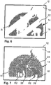
- Fig. 6 shows exemplary strip-shaped regions 22 in which the marker 19 is missing.
- Fig. 7 shows a development in which in the area 14 different motifs are represented by different patterns 24, 26 and 28, which differ in their geometry of the dot matrix.
- a pentagonal grid R1 is used for the background, a square grid R2 for the elephant and a hexagonal grid R3 for the baby elephant.
- a good recognition of the three patterns 24, 26 and 28 can also be achieved, in particular with comparatively large holes which are to be resolved with the eye, whereas no distinction appears in supervision.
- the geometry differences may also affect other parameters, as explained in the general part of the description.
- Fig. 8 shows a plan view of a further embodiment of the security feature 12. Elements which correspond to those of the previous embodiments are provided with the same reference numerals, so that their description need not be repeated.
- the security feature 12 includes edge-colored holes 16, which are arranged in a grid R. At individual positions in the grid R no hole 16, but only a colored dot 49 is formed.
- the thus formed surface of holes 16 thus has not only an outer boundary, the in Fig. 8 has the shape of an "L" but also has an inner boundary that effects encodings 50.
- the dots 49 are held in the same color as the marker 19 of the holes 16 is colored. As a result, the colored dots 49 can not be seen in plan view of the security feature 12. They appear in the same color as the rest of the area, which is colored by the colored edges of the holes 16. When viewed in transmitted light, the missing holes 16 of course fall immediately, so that the codes 50 are clearly visible.
- Fig. 9 shows a modification of the embodiment of the Fig. 8 in that a plurality of inner boundaries are present, by the security feature 12 alternates of line-lined holes 16 formed with line-shaped colored dots 49 is formed. Again, a motif is visible in plan view, for example in the form of a "P", which contains a line structure when viewed through the holes 16.
- the colored dots 49 are again colored in the color which the marker 19 has at the edges of the holes 16.
- the security element of Fig. 9 is thus made up of a plurality of surfaces, each of which is formed of line-shaped juxtaposed holes 16.
- the embodiment of the Fig. 9 thus makes a modification Fig. 8 not a surface having inner and outer boundaries, but a plurality of adjacent, here line-shaped surfaces, the optional feature being that these surfaces are arranged together with colored dots 49 in a common grid R with respect to the points and the holes ,
- Fig. 8 and 9 Due to the embodiments according to Fig. 8 and 9 for example, designs may be combined and / or hidden information, such as numbers, geometries, or specific encodings within the raster, that are visible only when viewed through the holes 16. This is possible for example by the colored dots 49 are hidden within a grid R (embodiment of the Fig. 8 ) or by the adjacent and colored holes 16 are visible only in transmitted light ( Fig. 9 ).
- the adjacent holes which are directly adjacent to one another, can also be arranged in the form of a line which, for example, represents a colored border of a motif, this border then clearly emerging when viewed through the holes 16.
- a paper 18 has been mentioned by way of example as substrate of the banknote.
- a film or the like may be used as the substrate be used, for example, in a window area of a banknote.
Landscapes
- Physics & Mathematics (AREA)
- Health & Medical Sciences (AREA)
- Electromagnetism (AREA)
- General Health & Medical Sciences (AREA)
- Toxicology (AREA)
- Engineering & Computer Science (AREA)
- Manufacturing & Machinery (AREA)
- Optics & Photonics (AREA)
- Laser Beam Processing (AREA)
- Credit Cards Or The Like (AREA)
- Thermal Transfer Or Thermal Recording In General (AREA)
Description
Die Erfindung betrifft ein Verfahren zur Herstellung eines Sicherheitsmerkmals für ein Sicherheitselement, ein Sicherheitspapier oder einen Datenträger, das einen Träger aufweist, wobei der Träger durch Laserstrahlung hinsichtlich seiner Farbe modifizierbar ist, durch Einwirkung von im Strahlquerschnitt intensitätsverteilter Laserstrahlung Löcher von bestimmtem Lochdurchmesser in den Träger eingebracht werden, die einen Rand haben, wobei zugleich aufgrund der Intensitätsverteilung über den Strahlquerschnitt in einer den Rand umgebenden Zone bestimmter Zonenbreite der Träger durch die Laserstrahlung modifiziert wird, so dass der Rand farbig ist. Die Erfindung betrifft weiter ein Sicherheitsmerkmal für ein Sicherheitselement, ein Sicherheitspapier oder einen Datenträger, das einen Träger aufweist, der hinsichtlich seiner Farbe modifizierbar ist, in den Träger Löcher von bestimmtem Lochdurchmesser eingebracht sind, die einen Rand haben, und in einer den Rand umgebenden Zone bestimmter Zonenbreite der Träger modifiziert ist, so dass der Rand farbig ist, sowie ein Sicherheitselement, ein Sicherheitspapier und ein Wertdokument oder einen Datenträger mit einem solchen Sicherheitsmerkmal.The invention relates to a method for producing a security feature for a security element, a security paper or a data carrier having a carrier, wherein the carrier is modifiable by laser radiation in terms of its color, introduced by the action of laser beam in the beam cross-section intensity laser holes of certain hole diameter in the carrier be having an edge, wherein at the same time due to the intensity distribution over the beam cross section in a zone surrounding the edge of certain zone width of the carrier is modified by the laser radiation, so that the edge is colored. The invention further relates to a security feature for a security element, a security paper or a data carrier, which has a carrier that is modifiable in color, in the carrier holes of certain hole diameter are introduced, which have an edge, and in a surrounding zone of the edge certain zone width of the carrier is modified so that the edge is colored, as well as a security element, a security paper and a document of value or a data carrier with such a security feature.
Ausweiskarten, wie beispielsweise Kreditkarten oder Personalausweise, werden oft mittels Lasergravur mit einer individuellen Kennzeichnung versehen. Auch das Erzeugen durchgehender Öffnungen in Wertdokumenten, z.B. Banknotenpapieren, durch Laserschneiden ist seit Längerem bekannt. So ist beispielsweise in der Druckschrift
Die
Eine farbige Umrandung von Löchern ist auch aus der
Auf Laserstrahlung empfindliche Markierungsstoffe sind beispielsweise aus folgenden Druckschriften bekannt:
Der Erfindung liegt deshalb die Aufgabe zugrunde, ein Sicherheitselement, Sicherheitspapier und Datenträger der eingangs genannten Art hinsichtlich der Nachahmungssicherheit weiter zu verbessern und die Herstellbarkeit zu vereinfachen.The invention is therefore based on the object, a security element, security paper and data carriers of the type mentioned above To further improve the imitation security and to simplify the manufacturability.
Diese Aufgabe wird gelöst durch ein Verfahren zur Herstellung eines Sicherheitsmerkmals für ein Sicherheitselement, ein Sicherheitspapier oder einen Datenträger, wobei ein Träger bereitgestellt wird, der durch Laserstrahlung hinsichtlich seiner Farbe modifizierbar ist, durch Einwirkung von im Strahlquerschnitt intensitätsverteilter Laserstrahlung Löcher von bestimmtem Lochdurchmesser in den Träger eingebracht werden, die einen Rand haben, wobei zugleich aufgrund der Intensitätsverteilung über den Strahlquerschnitt in einer den Rand umgebenden Zone bestimmter Zonenbreite der Träger durch die Laserstrahlung modifiziert wird, so dass der Rand farbig ist, wobei die Löcher eine Fläche überdeckend angeordnet werden und innerhalb der Fläche benachbarte Löcher in einem auf das Lochzentrum bezogenen Lochabstand voneinander angeordnet werden, der nicht größer ist als das 2,5-fache der Summe aus maximalem Lochdurchmesser und doppelter Zonenbreite.This object is achieved by a method for producing a security feature for a security element, a security paper or a data carrier, wherein a carrier is provided, which is modifiable by laser radiation in terms of its color, by the action of laser beam in the beam cross-section laser radiation holes of certain hole diameter in the carrier are introduced, which have an edge, wherein at the same time due to the intensity distribution over the beam cross section in a zone surrounding the edge zone width of the carrier is modified by the laser radiation, so that the edge is colored, the holes are arranged covering a surface and within the Area adjacent holes are arranged in a relation to the hole center hole spacing from each other, which is not greater than 2.5 times the sum of maximum hole diameter and double zone width.
Die Aufgabe wird weiter gelöst durch ein Verfahren zur Herstellung eines Sicherheitsmerkmals für ein Sicherheitselement, ein Sicherheitspapier oder einen Datenträger, wobei ein Träger bereitgestellt wird, der durch Laserstrahlung hinsichtlich seiner Farbe modifizierbar ist, durch Einwirkung von im Strahlquerschnitt intensitätsverteilter Laserstrahlung Löcher von bestimmtem Lochdurchmesser in den Träger eingebracht werden, die einen Rand haben, wobei zugleich aufgrund der Intensitätsverteilung über den Strahlquerschnitt in einer den Rand umgebenden Zone bestimmter Zonenbreite der Träger durch die Laserstrahlung modifiziert wird, so dass der Rand farbig ist, wobei die Löcher eine Fläche überdeckend angeordnet werden und innerhalb der Fläche die Löcher mindestens 50% der Größe der Fläche ausmachen.The object is further achieved by a method for producing a security feature for a security element, a security paper or a data carrier, wherein a carrier is provided, which is modifiable by laser radiation in terms of its color, by the action of laser beam in the beam cross-section intensity-distributed laser holes of certain hole diameter in the Carrier are introduced, which have an edge, wherein at the same time due to the intensity distribution over the beam cross section in a zone surrounding the edge zone width of the carrier is modified by the laser radiation, so that the edge is colored, the holes are arranged covering a surface and within the area the holes make up at least 50% of the size of the area.
Die Aufgabe wird ebenfalls gelöst durch ein Sicherheitsmerkmal für ein Sicherheitselement, ein Sicherheitspapier oder einen Datenträger, das einen Träger aufweist, wobei der Träger hinsichtlich seiner Farbe durch Laserstrahlung modifizierbar ist, in den Träger Löcher von bestimmtem Lochdurchmesser eingebracht sind, die einen Rand haben, und in einer den Rand umgebenden Zone bestimmter Zonenbreite der Träger modifiziert ist, so dass der Rand farbig ist, wobei die Löcher eine Fläche überdeckend angeordnet sind und innerhalb der Fläche alle benachbarten Löcher in einem auf das Lochzentrum bezogenen Lochabstand voneinander angeordnet sind, der nicht größer ist als das 2,5-fache der Summe aus maximalem Lochdurchmesser und doppelter Zonenbreite.The object is also achieved by a security feature for a security element, a security paper or a data carrier having a carrier, wherein the carrier is modifiable in terms of its color by laser radiation, in the carrier holes of a certain hole diameter are introduced, which have an edge, and in a zone of certain zone width surrounding the edge, the support is modified so that the edge is colored, the holes being arranged overlapping one surface and within the surface all adjacent holes are arranged in a hole center distance spaced from each other which is not larger as 2.5 times the sum of maximum hole diameter and double zone width.
Die Aufgabe wird auch gelöst durch ein Sicherheitsmerkmal für ein Sicherheitselement, ein Sicherheitspapier oder einen Datenträger, das einen Träger aufweist, wobei der Träger hinsichtlich seiner Farbe durch Laserstrahlung modifizierbar ist, in den Träger Löcher von bestimmtem Lochdurchmesser eingebracht sind, die einen Rand haben, und in einer den Rand umgebenden Zone bestimmter Zonenbreite der Träger modifiziert ist, so dass der Rand farbig ist, wobei die Löcher eine Fläche überdeckend angeordnet sind und innerhalb der Fläche die Löcher mindestens 50% der Größe der Fläche ausmachen.The object is also achieved by a security feature for a security element, a security paper or a data carrier having a carrier, wherein the carrier is modifiable in terms of its color by laser radiation, in the carrier holes of certain hole diameter are introduced, which have an edge, and in a zone of certain zone width surrounding the edge, the carrier is modified such that the edge is colored, the holes covering one surface and within the surface the holes make up at least 50% of the size of the surface.
Das Prinzip der Erfindung sieht somit vor, die Fläche zu perforieren, wobei die genannten geometrischen Vorgaben eingehalten werden. Die Perforation erlaubt es dabei, die Fläche hinsichtlich einer äußeren oder inneren Berandung zu strukturieren. Die äußere Berandung der Fläche kann dann ein Motiv codieren. Weiter können innerhalb der Fläche Aussparungen vorgesehen sein, in denen keine Perforationen vorgesehen sind, so dass auch eine innere Berandung gegeben ist, die zum Motiv beitragen kann.The principle of the invention thus provides to perforate the surface, wherein said geometric specifications are met. The perforation makes it possible to structure the surface with respect to an outer or inner boundary. The outer boundary of the surface can then be a motif encode. Further, recesses can be provided within the surface, in which no perforations are provided, so that an inner boundary is given, which can contribute to the motif.
Im mathematischen Sinne ist die perforierte Fläche damit mindestens wegzusammenhängend, ohne innere Berandung auch einfach zusammenhängend.In the mathematical sense, the perforated surface is thus at least path-coherent, without inner boundary also simply connected.
Natürlich können mehrere Flächen vorgesehen sein, die unter anderem auch identisch wiederholt sein können, beispielsweise in Form mehrerer, jeweils eine Fläche ausbildenden Linien, die nebeneinanderliegen.Of course, a plurality of surfaces can be provided which, among other things, can also be identical, for example in the form of a plurality of lines, each forming a surface, which lie next to one another.
Der Begriff der "benachbarten Löcher" bezieht sich auf die Form der Fläche. Hat die Fläche, wie beispielshalber genannt, eine innere Berandung, d.h. mindestens eine Aussparung, und eine äußere Berandung, sind die an der jeweiligen Berandung liegenden Löcher zu den innerhalb der Fläche liegenden Löchern benachbart, natürlich nicht zum Gebiet außerhalb der Berandung, an der die Fläche innen oder außen endet.The term "adjacent holes" refers to the shape of the surface. If the surface has an inner boundary, as it is called by way of example, i. at least one recess, and an outer boundary, the holes lying at the respective boundary are adjacent to the holes lying within the surface, of course not to the area outside the boundary, at which the surface ends inside or outside.
Ein Gebiet außerhalb der Berandung der Fläche kann bevorzugt mit einer Einfärbung versehen werden, die der der Lochränder gleicht. Dann ergibt sich in Draufsicht der Effekt, dass die Berandung der Fläche zumindest zum Teil nicht zu erkennen ist, in Durchsicht, wenn die Löcher sichtbar werden, jedoch klar hervortritt.An area outside the boundary of the area may preferably be provided with a coloration which is similar to that of the hole edges. Then, in plan view, the effect that the boundary of the surface is at least partially not visible, in view when the holes are visible, but clearly emerges.
Die Löcher können insbesondere in einem Punktraster angeordnet werden. Dabei sind verschiedene Rasterstrukturen möglich, wie hexagonale Raster, rechteckige Raster etc.The holes can be arranged in particular in a dot matrix. Various raster structures are possible, such as hexagonal rasters, rectangular rasters etc.
Für Flächen mit einer inneren Berandung ist es bevorzugt, an einzelnen Stellen des Punktrasters keine Löcher auszubilden, und damit die Aussparung und die innere Berandung zu schaffen. Diese Stellen können in einer weiter bevorzugten Ausgestaltung in der Farbe der Lochränder gefärbt sein, z.B. durch dem Lochraster entsprechend angeordnete Punkte, und ganz besonders bevorzugt ein Motiv, Zeichen oder Symbol codieren, das in Draufsicht nicht oder schlecht, in Durchsicht jedoch klar erkennbar ist.For surfaces with an inner boundary, it is preferable not to form holes at individual points of the dot matrix, and thus to create the recess and the inner boundary. These sites may in a further preferred embodiment be colored in the color of the hole edges, e.g. correspondingly arranged points, and most preferably a motif, encode sign or symbol, which is not or poorly in plan view, but clearly visible in the see through.
Die Erfindung verwendet eine spezielle Anordnung der Löcher in der perforierten Fläche, um den in der
Der Farbeffekt wird in einigen Ausführungsformen erreicht, indem ein Träger verwendet ist, der mit der Laserstrahlung direkt modifizierbar ist. In anderen Ausführungsformen wird der Träger zuvor mit einem geeigneten Markierungsstoff versehen, z.B. beschichtet, der modifizierbar ist.The color effect is achieved in some embodiments by using a support that is directly modifiable with the laser radiation. In other embodiments, the support is previously provided with a suitable marker, e.g. coated, which is modifiable.
Der Farbeffekt wird umso stärker, je geringer der Abstand zwischen den Lochrändern, also je dichter die Perforation der Fläche ist. Durch den Bezug des Lochabstandes auf das Lochzentrum, also die Angabe des Lochabstandes als Abstand zwischen den Lochzentren benachbarter Löcher, erreicht das Merkmal, dass der auf das Lochzentrum bezogene Lochabstand nicht größer ist als das 2,5-fache der Summe aus Lochdurchmesser und doppelter Zonenbreite, dass die farbig veränderten Zonen einen vergleichsweise großen Anteil an der durchlöcherten Fläche haben. Dies sichert einen besonders guten Farbeindruck. Er steigt natürlich, je höher der Anteil der farbig markierten Zonen an der verbleibenden Trägerfläche ist. Deshalb ist es alternativ vorgesehen, dass dieser Anteil mindestens 50%, bevorzugt sogar 75% oder 90% beträgt. Idealerweise besteht zwischen den benachbarten Löchern ein minimaler Spalt, der der 2-fachen Zonenbreite entspricht. Im Bereich dieses minimalen Spalts stoßen dann farbig markierte Zonen direkt aneinander. Aufgrund der Kreisgeometrie der mit dem Laserstrahl erzeugten Löcher gibt es natürlich Bereiche zwischen benachbarten Löchern, in denen nicht der minimale Spalt gegeben ist. Der minimale Spalt besteht auf der Verbindungsgeraden zwischen den Lochzentren.The color effect becomes stronger, the smaller the distance between the edges of the holes, ie the denser the perforation of the surface. By reference the hole spacing on the center of the hole, so the indication of the hole spacing as the distance between the hole centers of adjacent holes, achieved the feature that the hole spacing related to the hole center is not greater than 2.5 times the sum of hole diameter and double zone width, that the colored zones have a comparatively large proportion of the perforated area. This ensures a particularly good color impression. It increases naturally, the higher the proportion of the color-coded zones on the remaining support surface. Therefore, it is alternatively provided that this proportion is at least 50%, preferably even 75% or 90%. Ideally, there is a minimum gap between the adjacent holes that is twice the zone width. In the area of this minimum gap, color-coded zones then encounter each other directly. Of course, due to the circular geometry of the holes created by the laser beam, there are areas between adjacent holes where the minimum gap is not present. The minimum gap exists on the connecting line between the hole centers.
Die erfindungsgemäße perforierte Fläche erscheint in Draufsicht farbig aufgrund des Farbeffektes, z.B. durch den Markierungsstoff, der in den Zonen rund um die Löcher modifiziert ist. Gleichzeitig ergibt sich im Durchlicht aufgrund der Perforation der Fläche und der damit geänderten Transluzenz ebenfalls ein Motiv. Diese beiden Motive liegen im perfekten Passer zueinander, da sie durch ein- und denselben Vorgang, nämlich die Perforation der Fläche, erzeugt wurden.The perforated surface according to the invention appears colored in plan view due to the color effect, e.g. by the marker modified in the zones around the holes. At the same time, there is also a motive in transmitted light due to the perforation of the surface and the thus changed translucency. These two motifs are in perfect register with each other, since they were created by one and the same process, namely the perforation of the surface.
Die perforierte Fläche ist in x- und y-Richtung größer als ein Loch. Es handelt sich also um ein zweidimensionales Gebiet, in dem Löcher in beiden Koordinatenrichtungen nebeneinanderliegen.The perforated surface is larger in the x and y direction than a hole. It is therefore a two-dimensional area in which holes are juxtaposed in both coordinate directions.
Das Vorsehen eines Markierungsstoffs ist hingegen für den Passer dieser beiden Motive nicht weiter relevant. Prinzipiell ist es möglich, den Markierungsstoff vollflächig in einem sehr viel größeren Bereich vorzusehen, als die durchlöcherte Fläche einnimmt. In einer Weiterbildung wird die Aufbringung bzw. das Vorsehen des Markierungsstoffes und die Struktur der durchlöcherten Fläche so kombiniert, dass in einzelnen Teilen der Fläche kein Markierungsstoff vorhanden ist. In diesen Teilen haben die Löcher dann keinen farbigen Rand. In den verbleibenden Teilen ist der Markierungsstoff hingegen vorhanden und die Ränder der Löcher sind farbig. Dies gibt eine weitere, schwer nachzuahmende Erscheinung des Sicherheitsmerkmals. Wird der Markierungsfarbstoff nur bereichsweise vorgesehen oder aufgedruckt, sieht man im Auflicht nur in diesen Bereichen die farbige Struktur des Motives und in anderen nicht. Dies regt zu einer Betrachtung im Durchlicht an.The provision of a marker, however, is not relevant to the passport of these two motifs. In principle, it is possible to provide the marking substance over the entire area in a much larger area than the perforated area occupies. In a further development, the application or provision of the marking substance and the structure of the perforated surface are combined in such a way that no marking substance is present in individual parts of the surface. In these parts, the holes then have no colored border. In the remaining parts, however, the marker is present and the edges of the holes are colored. This gives another appearance of the security feature that is difficult to imitate. If the marking dye is only provided or printed in certain areas, the colored structure of the motif can only be seen in the reflected light and not in others. This encourages viewing in transmitted light.
Durch Variation des Lochabstandes kann die Fläche einen bestimmten Designeindruck vermitteln. Es ist deshalb in einer Weiterbildung bevorzugt, dass die Fläche ein erstes und mindestens ein zweites Muster aufweist, die sich hinsichtlich der Rasterstruktur, in der die Löcher angeordnet sind, und/ oder des Lochdurchmessers und/ oder des Lochabstandes unterscheiden.By varying the hole spacing, the surface can convey a certain design impression. It is therefore preferred in a development that the surface has a first and at least one second pattern, which differ with respect to the grid structure in which the holes are arranged, and / or the hole diameter and / or the hole spacing.
Der laserstrahlungsmodifizierbare Träger oder dessen Markierungsstoff wird beim Einbringen der Löcher in den Träger durch den Laserstrahl modifiziert. Dabei wird ausgenutzt, dass die Laserstrahlenergie in einem äußeren Bereich des Strahlquerschnitts ausreicht, um in der Zone um den Rand der Löcher den Markierungsstoff zu modifizieren. Auf diese Weise ist automatisch eine perfekte Passerung von Öffnungen und laserstrahlungsmodifizierte Zone gewährleistet.The laser-radiation-modifiable carrier or its marking substance is modified by the laser beam when the holes are introduced into the carrier. In this case, use is made of the fact that the laser beam energy in an outer region of the beam cross-section is sufficient to modify the marking substance in the zone around the edge of the holes. In this way, a perfect registration of openings and laser radiation-modified zone is automatically ensured.
Will man den Träger mit dem Markierungsstoff versehen, wird er in einer vorteilhaften Erfindungsvariante auf seiner Oberfläche mit dem Markierungsstoff beschichtet, beispielsweise durch ein Druckverfahren. Nach einer anderen ebenfalls vorteilhaften Variante der Erfindung wird der Markierungsstoff in das Volumen des Trägers eingebracht. Dafür stehen je nach Trägermaterial verschiedene Verfahren zur Verfügung.If you want to provide the carrier with the marker, it is coated in an advantageous variant of the invention on its surface with the marker, for example by a printing process. According to another likewise advantageous variant of the invention, the marking substance is introduced into the volume of the carrier. Depending on the carrier material, different methods are available.
Ist der Träger aus Papier gebildet, kann der Markierungsstoff mit Vorteil schon bei der Blattbildung der Papiermasse beigemischt werden. Eine weitere vorteilhafte Möglichkeit besteht darin, den Markierungsstoff in einem Tauchbad in das Volumen des Papiersubstrats einzubringen oder das Papiersubstrat, z.B. in einer Leimpresse, mit dem Markierungsstoff zu imprägnieren.If the carrier is formed from paper, the marker can advantageously be mixed with the sheet formation of the paper pulp. A further advantageous possibility is to introduce the marking substance into the volume of the paper substrate in a dipping bath or to mix the paper substrate, e.g. in a size press, to impregnate with the marker.
Natürlich kann ein Träger auch ohne zusätzlichen Markierungsstoff laserstrahlungsmarkierbar sein. Eine Schwärzung durch einen thermischen Effekt ist nur ein Beispiel hierfür. Ist der Träger aus einer Kunststofffolie gebildet, kann z.B. die Folie thermoreaktiv ausgebildet sein oder kann der Markierungsstoff bereits bei der Herstellung der Folie oder nachträglich durch einen Imprägnierungsschritt in das Volumen der Folie eingebracht werden.Of course, a carrier may also be laser-irradiated without additional tagging material. A blackening by a thermal effect is just one example of this. If the carrier is formed from a plastic film, e.g. the film may be formed thermoreactive or the marker may already be introduced into the volume of the film during the production of the film or subsequently by an impregnation step.
Als Markierungsstoff kommen mit Vorteil Stoffe infrage, deren sichtbare Farbe durch die Einwirkung der Laserstrahlung verändert wird. Hierzu können beispielsweise thermoreaktive Farbpigmente, wie etwa Ultramarinblau verwendet werden. Mit Vorteil können auch Markierungsstoffe eingesetzt werden, deren Infrarot-absorbierende Eigenschaften oder deren magnetische, elektrische oder lumineszierende Eigenschaften durch die Einwirkung der Laserstrahlung verändert werden. Sicherheitsmerkmale mit derartigen laserstrahlungsmodifizierten Lochrändern können insbesondere für die maschinelle Echtheitsprüfung eingesetzt werden. Auch der Einsatz einer Kombination verschiedener Markierungsstoffe kommt in Betracht, beispielsweise um sowohl eine visuelle als auch eine maschinelle Echtheitsprüfung des Sicherheitsmerkmals zu ermöglichen. Bei Verwendung mehrerer Markierungsstoffe können diese sowohl nebeneinander als auch in verschiedenen Schichten übereinander zu liegen kommen. Alternativ kann in einer erfindungsgemäßen Ausführungsform die Modifikation des Trägers/Markierungsstoffes in einer Abtragung oder Zerstörung bestehen. Beim Markierungsstoff handelt es sich in diesem Fall bevorzugt um eine metallische Beschichtung.As a marker material come into question with advantage whose visible color is changed by the action of the laser radiation. For example, thermoreactive colored pigments such as ultramarine blue can be used for this purpose. Advantageously, it is also possible to use marking substances whose infrared-absorbing properties or their magnetic, electrical or luminescent properties are changed by the action of the laser radiation. Security features with such laser radiation modified hole edges can be particularly for the machine Authenticity test be used. It is also possible to use a combination of different marking substances, for example in order to enable both a visual and a machine authenticity check of the security feature. When using several markers, these can come to lie next to each other as well as in different layers one above the other. Alternatively, in one embodiment of the invention, the modification of the carrier / marker may be erosion or destruction. The marker is preferably a metallic coating in this case.
Bei einer vorteilhaften Verfahrensführung werden durch den Laserschnitt im Träger Löcher mit schräger Schnittkante erzeugt. Eine schräge Schnittkante kann beispielsweise dadurch sichergestellt werden, dass der Laserstrahl beim Erzeugen der Öffnungen unter einem vorbestimmten Winkel zur Oberflächennormalen des Trägers geführt wird. Je nach gewähltem Schnittwinkel lässt sich dabei die Größe der Randzone einstellen, wie weiter unten genauer erläutert werden wird.In an advantageous procedure, holes are produced with an oblique cutting edge by the laser cut in the carrier. An oblique cutting edge can be ensured, for example, by guiding the laser beam at a predetermined angle to the surface normal of the carrier when producing the openings. Depending on the selected cutting angle, the size of the edge zone can be set, as will be explained in more detail below.
Gemäß einer vorteilhaften Erfindungsvariante werden als laserstrahlungsmodifizierbarer Markierungsstoff laserstrahlungsmodifizierbare Effektpigmente eingesetzt. Derartige Effektpigmente stehen dem Fachmann mit unterschiedlichen Eigenschaften, insbesondere bezüglich ihrer Körperfarbe, dem Farbumschlag unter Laserstrahlungseinwirkung, der Schwellenergie und der benötigten Laserstrahlungswellenlänge zur Verfügung. Auch Effektpigmente, die unter Laserstrahlung nicht (nur) ihre sichtbare Farbe, sondern ihre Infrarot-absorbierenden, magnetischen, elektrischen oder lumineszierenden Eigenschaften verändern, sind dem Fachmann bekannt. Die Modifikation der Effektpigmente kann mit Laserstrahlung im ultravioletten, sichtbaren oder infraroten Spektralbereich, beispielsweise mit einem CO2-Laser einer Wellenlänge von 10600 nm erfolgen.According to an advantageous variant of the invention, laser radiation-modifiable effect pigments are used as the laser-radiation-modifiable marker. Such effect pigments are available to the person skilled in the art with different properties, in particular with respect to their body color, the color change under laser radiation, the threshold energy and the required laser radiation wavelength. Also, effect pigments which change not only their visible color under laser radiation but their infrared-absorbing, magnetic, electrical or luminescent properties are known to the person skilled in the art. The modification of the effect pigments can be done with laser radiation in the ultraviolet, visible or infrared spectral range, for example with a CO 2 laser of a wavelength of 10600 nm.
Bei einer weiteren ebenfalls vorteilhaften Erfindungsvariante wird ein pigmentfreier laserstrahlungsmodifizierbarer Markierungsstoff eingesetzt. Auch pigmentfreie Markierungsstoffe können, beispielsweise als Stichtiefdruck-oder Druckfarbe, auf den Träger aufgebracht oder in das Trägervolumen eingebracht werden. Mit pigmentfreien Markierungsstoffen lässt sich eine Beschichtung hoher Transparenz erzeugen, in die durch Lasereinwirkung mit hoher Geschwindigkeit eine dauerhafte und kontrastreiche Markierung eingebracht werden kann. Pigmentfreie Markierungsstoffe können durch Laserstrahlung im ultravioletten, sichtbaren oder infraroten Spektralbereich, beispielsweise mit der 10600 nm-Strahlung eines CO2-Lasers modifiziert werden. Konkrete, nicht beschränkende Beispiele für pigmentfreie lasermodifizierbare Markierungsstoffe sind in den Druckschriften
Die Erfindung umfasst auch ein Sicherheitselement für Sicherheitspapiere, Wertdokumente und dergleichen mit einem nach dem beschriebenen Verfahren hergestellten Sicherheitsmerkmal, wobei das Sicherheitselement einen Träger aufweist, in den durch Einwirkung von Laserstrahlung eine Fläche durchlöchert wird und der laserstrahlungsmodifizierbar ist. Ein derartiges Sicherheitselement kann beispielsweise in Form eines Sicherheitsfadens, eines Etiketts, eines Transferelements oder einer Abdeckfolie für einen Fensterbereich oder ein Loch in einem Wertdokument, wie etwa einer Banknote, ausgebildet sein.The invention also encompasses a security element for security papers, documents of value and the like with a security feature produced according to the method described, wherein the security element has a carrier into which a surface is perforated by the action of laser radiation and which is laser-radiation-modifiable. Such a security element may for example be in the form of a security thread, a label, a transfer element or a covering film for a window area or a hole in a value document, such as a banknote.
Daneben umfasst die Erfindung auch ein Sicherheitspapier für die Herstellung von Wertdokumenten oder dergleichen mit einem nach dem beschriebenen Verfahren hergestellten Sicherheitsmerkmal, wobei das Sicherheitspapier einen Träger aufweist, der eine Fläche aufweist, die durch Einwirkung von Laserstrahlung durchlöchert ist und der laserstrahlungsmodifizierbar ist. Anstatt die Löcher direkt in das Sicherheitspapier einzubringen, kann dieses auch mit einem Sicherheitselement der oben beschriebenen Art versehen sein. Die Erfindung enthält weiter einen Datenträger mit einem nach dem beschriebenen Verfahren hergestellten Sicherheitsmerkmal, insbesondere ein Wertdokument wie eine Banknote, Ausweiskarte oder dergleichen, wobei der Datenträger einen Träger aufweist.In addition, the invention also includes a security paper for the production of documents of value or the like with a security feature produced by the described method, wherein the security paper has a carrier which has a surface which is perforated by the action of laser radiation and which is laser radiation modifiable. Instead of introducing the holes directly into the security paper, this can also be provided with a security element of the type described above. The invention further includes a data carrier with a security feature produced by the method described, in particular a value document such as a banknote, identity card or the like, wherein the data carrier has a carrier.
Weitere Ausführungsbeispiele sowie Vorteile der Erfindung werden nachfolgend anhand der Figuren erläutert, bei deren Darstellung auf eine maßstabs- und proportionsgetreue Wiedergabe verzichtet wurde, um die Anschaulichkeit zu erhöhen.Further exemplary embodiments and advantages of the invention are explained below with reference to the figures, in the representation of which a representation true to scale and proportion has been dispensed with in order to increase the clarity.
Es zeigen:
- Fig. 1
- eine schematische Darstellung einer Banknote mit einem Sicherheitsmerkmal,
- Fig. 2
- eine Detailaufsicht auf das Sicherheitsmerkmal der
Fig. 1 , - Fig. 3(a)-(c)
- die Erläuterung der Herstellung des Sicherheitsmerkmals, wobei
Fig. 3(a) schematisch eine räumliche Energieverteilung eines Laserstrahls,Fig. 3(b) eine räumliche Verteilung der beim Schneiden entstehenden Wärmeenergie, undFig. 3(c) detailliert die Abmessungen von durch den Laserstrahl erzeugten Löchern zeigt, - Fig. 4
- eine Detailansicht auf das Sicherheitsmerkmal,
- Fig. 5(a)-(c)
- Querschnittdarstellungen eines Lochs des Sicherheitsmerkmales, wobei
Fig. 5(a) die Situation vor der Einstrahlung der Laserstrahlung zeigt undFig. 5(b) und (c) zwei Löcher mit unterschiedlich breitem Randeffekt zeigen, und - Fig. 6 - 9
- Aufsichten auf ein Sicherheitsmerkmal nach weiteren Ausführungsformen.
- Fig. 1
- a schematic representation of a banknote with a security feature,
- Fig. 2
- a close attention to the security feature of
Fig. 1 . - Fig. 3 (a) - (c)
- the explanation of the production of the security feature, wherein
Fig. 3 (a) schematically a spatial energy distribution of a laser beam,Fig. 3 (b) a spatial distribution of the heat energy generated during cutting, andFig. 3 (c) detailed the Dimensions of holes created by the laser beam, - Fig. 4
- a detailed view of the security feature,
- Fig. 5 (a) - (c)
- Cross-sectional views of a hole of the security feature, wherein
Fig. 5 (a) the situation before the irradiation of the laser radiation shows andFig. 5 (b) and (c) show two holes with different width edge effect, and - Fig. 6-9
- Supervision of a security feature according to further embodiments.
Die Erfindung wird am Beispiel einer Banknote erläutert.
In
Vor der Einbringung der Löcher 16 wurde das Papier 18 mindestens im Bereich der Fläche 14 mit einem Markierungsstoff versehen, der durch Einwirkung von Laserstrahlung hinsichtlich eines Farbeffektes modifizierbar ist. Beispielsweise hat der Markierungsstoff Effektpigmente, die bei geeigneter Bestrahlung von einem transparenten, nicht farbigen Zustand in einen roten Zustand wechseln. Jedes Loch 16 hat einen Rand, an dem eine Zone liegt, in welcher der Markierungsstoff modifiziert wurde. Dies erfolgte durch die Einwirkung der Laserstrahlung, d.h. das Einbringen eines Loches und die Modifizierung des Markierungsstoffes am Rand geschieht für jedes Loch 16 gleichzeitig.Before the introduction of the
Das Prinzip der gleichzeitigen Erzeugung der Löcher 16 und deren Randgestaltung ist in
In einem inneren Bereich, einem Schnittbereich 32, überschreitet die Laserstrahlintensität die zum Schneiden des Papiers 18 benötigte Mindestenergie E1. Mit E2 ist in
Das Papier 18 wird daher beim Laserschneiden durch den Laserstrahl in einer Zone am Rand jedes Loches 16 in perfekter Passerung zum Loch 16 verfärbt. Die Breite der farbigen Zone am Rand entspricht dabei der Breite des Markierungsbereichs 34 und hängt von der Intensitätsverteilung 30 über den Strahlquerschnitt, hier also der Reaktionsenergie der verwendeten Effektpigmente und den Materialeigenschaften des Papiers 18 ab.The
Außerhalb des Schnittbereichs 32 und des Markierungsbereichs 34 liegt die Laserstrahlintensität unterhalb der Reaktionsenergie der Effektpigmente, so dass das Papier 18 dort nicht farblich verändert wird.Outside the cutting
Der laserstrahlungsmodifizierbare Markierungsstoff 19 kann auf das Papier 18 aufgebracht, beispielsweise aufgedruckt werden (vgl.
Als Effektpigmente, die ihre sichtbare Farbe durch die Einwirkung der Laserstrahlung verändern, kommen beispielsweise thermoreaktive Farbpigmente, wie etwa Ultramarinblau, infrage.As effect pigments, which change their visible color by the action of the laser radiation, for example, thermoreactive color pigments, such as ultramarine blue, come into question.
Es versteht sich, dass auch zwei oder mehr Effektpigmente mit unterschiedlichen Schwellenergien oder eine Kombination aus visuell und maschinell nachweisbaren Effektpigmenten eingesetzt werden kann, um mehrere gepasserte Randeffekte zu erzeugen.It is understood that two or more effect pigments with different threshold energies or a combination of visually and mechanically detectable effect pigments can also be used to produce a plurality of registered edge effects.
Anstelle der beispielhaft beschriebenen Effektpigmente kann auch ein pigmentfreier laserstrahlungsmodifizierbarer Markierungsstoff eingesetzt werden. Auch solche Markierungsstoffe können, beispielsweise als Stichtiefdruck- oder Druckfarbe, auf das Papier 18 aufgedruckt oder in dessen Volumen eingebracht werden. Nicht pigmentierte, laserstrahlungsmodifizierbare Beschichtungen können im unbeschrifteten Zustand eine sehr hohe Transparenz aufweisen. Durch Einwirkung von Laserstrahlung, beispielsweise eines CO2-Lasers bei 10600 nm, lassen sich mit hoher Geschwindigkeit dauerhafte und kontrastreiche Markierungen, beispielsweise eine schwarze Beschriftung in der Beschichtung erzeugen.Instead of the effect pigments described by way of example, it is also possible to use a pigment-free laser-radiation-modifiable marker. Also, such markers can, for example, as intaglio or printing ink, printed on the
Neben der Modifikation des Markierungsstoffs 19 durch die Laserstrahlung selbst kommt auch eine Modifikation des Papiers 18 selbst infrage.In addition to the modification of the marking
Auch ist es möglich, dass die beim Laserstrahlschneiden erzeugte Wärme die Modifikation bewirkt. Auf diese Weise kann der modifizierte Randbereich der Öffnung optional sogar größer als die Strahlausdehnung sein, wie in
Wie bereits bei
Es ist dabei optional auch möglich, dass der Markierungsstoff 19 unmittelbar neben der Schnittkante abgetragen oder zerstört wird, und erst ab einem bestimmten kleinen Abstand von der Schnittkante modifiziert wird.It is optionally also possible that the
Aufgrund der nicht gleichförmigen, zum Rand des Strahlquerschnittes abfallenden Intensitätsverteilung 30 schafft man eine Zone 20, in der die Fluenz des Laserstrahls 44 über der eingangs genannten Reaktionsenergie E2 oder E2' liegt, jedoch unter der Mindestenergie, die zum Perforieren des Papiers 18 nötig ist. In diesem Bereich wird der Markierungsstoff 19 modifiziert, so dass eine ringförmige Zone 20 geschaffen wird, die das Loch 16 an der Eintrittsseite des Laserstrahls 44 umgibt und die farbig markiert ist. Das Loch 16 zeigt damit in Draufsicht einen farbigen Rand.Due to the non-uniform, falling to the edge of the beam
Damit die Ränder mehrerer Löcher 16 zusammen einen gut wahrnehmbaren Farbeindruck ergeben, werden die Löcher 16 in der perforierten Fläche 14 gemäß dem Punktraster R vergleichsweise eng gestaffelt, wie
Die Anordnung der Löcher in einem Punktraster ist optional. Es ist auch eine quasistatistische Anordnung der Löcher möglich, die die genannten Flächenanteile von Loch und Fläche einhält.The arrangement of the holes in a dot matrix is optional. It is also a quasi-statistical arrangement of the holes possible, which complies with the stated area proportions of hole and surface.
Der farbige Eindruck im Auflicht, der sich bei der Betrachtung der Fläche 16 durch die Aneinanderreihung von Zonen 20 einstellt, bleibt natürlich auch bei anderen Lochanordnungen und Lochabständen erhalten. Ab einem Lochabstand in der Größenordnung des 2,5-fachen Randdurchmessers E, also des 2,5-fachen der Summe aus maximalem Lochdurchmesser (C+2B) plus 2-facher Zonenbreite A, wird der farbige Eindruck ungenügend.The colored impression in the incident light, which arises when viewing the
Ein grüner Randeffekt kann beispielsweise mit Hilfe des Markierungsstoffes Manganese Ferrite F9900 M erzeugt werden. Dessen Farbumschlag geht von Grau nach Grün. Natürlich sind auch andere Farbumschläge denkbar, z.B. auch von Rot nach Grau mit dem Farbstoff Oxide Red PR222. Beide Farbstoffe sind von der Firma Cathay Industries. Ein Farbumschlag von Gelb zu Rot ist mit dem Farbstoff Eisenoxidgelb FeO(OH), erhältlich z.B. von Lanxess, möglich. Ein Farbumschlag von Türkis zu Schwarz ist mit dem Farbstoff Kupfer (II)-oxalat, erhältlich z.B. von Dr. Paul Lohmann GmbH, möglich.A green edge effect can be generated, for example, with the aid of the marking substance Manganese Ferrite F9900 M. Its color change goes from gray to green. Of course, other color changes are conceivable, for example, from red to gray with the dye Oxide Red PR222. Both dyes are from Cathay Industries. A color change from yellow to red is with the dye iron oxide yellow FeO (OH), available for example from Lanxess, possible. A color change from turquoise to black is with the dye copper (II) oxalate, available for example from Dr. med. Paul Lohmann GmbH, possible.
Wesentlich für das Erzeugen der Zone 20 zum Rand hin ist es, dass der Laserstrahl 44 eine Intensitätsverteilung hat, die nicht konstant ist, also kein Top-Hat-Profil aufweist. Jedes Intensitätsprofil, bei dem die Intensität des Laserstrahls 44 zum Rand des Strahlquerschnitts hin gegenüber dem Maximalwert abnimmt, kann für das Erzeugen einer Zone 20 angewendet werden, wobei die Art des Intensitätsprofils sich natürlich auf die Breite der Zone 20 relativ zum maximalen Lochdurchmesser (C+2B) jedes Lochs 16 auswirkt.It is essential for the generation of the
Wird durch den Laserstrahl eine schräge Lochkante im Papier 18 erzeugt, so kann der Randeffekt auch entlang der gesamten Lochkante ausgebildet sein, wie in
Durch Beaufschlagung des Papiers 18 mit der Laserstrahlung 44 wird ein schräger Lochrand 46 erzeugt, wie es die
Die
Statt den Lochabstand konstant zu lassen, kann durch eine Variation des Lochabstandes der Performation, z.B. durch laterale Variation des Punktrasters R oder durch rasterlose Anordnung der Löcher, ein bestimmter Designeindruck erhalten werden. Beispielsweise ist es möglich, im Bereich des Hintergrundes der Fläche 14 der
Wird, wie in
Das Sicherheitsmerkmal 12 umfasst randgefärbte Löcher 16, die in einem Raster R angeordnet sind. An einzelnen Positionen ist im Raster R kein Loch 16, sondern nur ein gefärbter Punkt 49 ausgebildet. Die derart gebildete Fläche aus Löchern 16 hat damit nicht nur eine äußere Berandung, die in
Durch die Ausgestaltungen gemäß
In einer weiteren Ausführungsform können die benachbarten Löcher, welcher direkt aneinandergrenzen auch in Form einer Linie angeordnet werden, die beispielsweise eine farbige Umrandung eines Motives darstellt, wobei diese Umrandung in Durchsicht durch die Löcher 16 dann klar hervortritt.In a further embodiment, the adjacent holes, which are directly adjacent to one another, can also be arranged in the form of a line which, for example, represents a colored border of a motif, this border then clearly emerging when viewed through the
Vorliegend wurde als Substrat der Banknote exemplarisch ein Papier 18 erwähnt. Natürlich kann als Substrat auch eine Folie oder ähnliches verwendet werden, die beispielsweise in einem Fensterbereich einer Banknote eingesetzt werden kann.In the present case, a
- 1010
- Banknotebill
- 1212
- Sicherheitsmerkmalsafety feature
- 1414
- Flächesurface
- 1616
- Lochhole
- 1818
- Papierpaper
- 1919
- Markierungsstofftracer
- 2020
- ZoneZone
- 2222
- BereichArea
- 24, 26, 2824, 26, 28
- Mustertemplate
- 3030
- Intensitätsverteilungintensity distribution
- 30'30 '
- WärmeenergieverteilungThermal energy distribution
- 3232
- Schnittbereichcutting area
- 34, 34'34, 34 '
- Markierungsbereichmarking region
- 4242
- Volumenvolume
- 4444
- Laserstrahlunglaser radiation
- 4646
- Lochrandhole edge
- 4848
- Randbereichborder area
- 4949
- gefärbter Punktcolored dot
- 5050
- Codierungencoding
- AA
- FarbeffektbreiteColor effect Width
- BB
- AbtragsbreiteAbtragsbreite
- CC
- LochdurchmesserHole diameter
- DD
- Lochabstandhole spacing
- Ee
- RandeffektdurchmesserEdge effect diameter
- E1, E1'E1, E1 '
- Mindestenergieminimum energy
- E2, E2'E2, E2 '
- Reaktionsenergiereaction energy
- RR
- Rastergrid
Claims (21)
- Method for producing a security feature for a security element, a security paper or a data carrier, wherein a substrate (18) is provided, the colour of which can be modified by laser radiation (44), holes (16) that have a specific hole diameter (C) and have a rim are introduced into the substrate (18) by the action of laser radiation (44) of which the intensity is distributed in the beam cross section (30), wherein at the same time, because of the intensity distribution (30) over the beam cross section, the substrate (18) is modified by the laser radiation (44) in a zone (20) of specific zone width (A) surrounding the rim, so that the rim is coloured, characterized in that the holes (16) perforate an area (14), wherein, within the area (14), all the adjacent holes (16) are arranged with a centre-to-centre hole spacing (D) from one another that is no greater than 2.5 times the sum of the maximum hole diameter (C+2B) and twice the zone width (A).
- Method according to Claim 1, characterized in that the hole spacing (D) is no greater than twice the sum of the maximum hole diameter and twice the zone width (A).
- Method for producing a security feature for a security element, a security paper or a data carrier, wherein a substrate (18) is provided, the colour of which can be modified by laser radiation (44), holes (16) that have a specific hole diameter (C) and have a rim are introduced into the substrate (18) by the action of laser radiation (44) of which the intensity is distributed in the beam cross section (30), wherein at the same time, because of the intensity distribution (30) over the beam cross section, the substrate (18) is modified by the laser radiation (44) in a zone (20) of specific zone width (A) surrounding the rim, so that the rim is coloured, characterized in that the holes (16) perforate an area (14), wherein, within the area (14), the holes (16) make up at least 50% of the size of the area.
- Method according to one of the above claims, characterized in that there is a minimum gap between the adjacent holes (16) which corresponds to twice the zone width (A).
- Method according to one of Claims 1 to 4, characterized in that the area has a first pattern (24) and at least one second pattern (26, 28), which differ with regard to the grid in which the holes are arranged and/or the hole diameter (C) and/or the hole spacing (D).
- Method according to one of Claims 1 to 5, characterized in that the substrate (18) is provided in which by the substrate (18) is provided with a marking substance (19), the colour of which can be modified by the laser radiation (44).
- Method according to Claim 6, characterized in that the marking substance (19) is applied to the substrate (18), wherein it covers only part of the area (14), so that only some of the holes (16) of the area (14) have the coloured rim.
- Method according to one of the above claims, characterized in that the holes (16) are arranged in accordance with a dot matrix (R).
- Method according to Claim 8, characterized in that at a plurality of locations (49) of the dot matrix (R), no holes (16) are formed and, instead, the substrate (18) is coloured in the colour of the rims, wherein the locations (49) of the dot matrix (R) overall preferably encode a motif (50) or character or symbol that can be seen in transmission.
- Security feature for a security element, a security paper or a data carrier, which has a substrate (18), wherein the colour of the substrate (18) can be modified by laser radiation (44), holes (16) that have a specific hole diameter (C) and have a rim are introduced into the substrate (18), and the substrate (18) is modified in a zone (20) of specific zone width (A) surrounding the rim, so that the rim is coloured, characterized in that the holes (16) perforate an area (14) and, within the area (14), all the adjacent holes (16) are arranged with a centre-to-centre hole spacing (D) from one another that is no greater than 2.5 times the sum of the maximum hole diameter (C+2B) and twice the zone width (A).
- Security feature according to Claim 10, characterized in that the hole spacing (D) is no greater than twice the sum of the maximum hole diameter (C+2B) and twice the zone width (A).
- Security feature for a security element, a security paper or a data carrier, which has a substrate (18), wherein the colour of the substrate (18) can be modified by laser radiation (44), holes (16) that have a specific hole diameter (C) and have a rim are introduced into the substrate (18), and the substrate (18) is modified in a zone (20) of specific zone width (A) surrounding the rim, so that the rim is coloured, characterized in that the holes (16) perforate an area (14) and, within the area (14), the holes (16) make up at least 50% of the size of the area (14).
- Security feature according to one of Claims 10 to 12, characterized in that there is a minimum gap between the adjacent holes (16) which corresponds to twice the zone width (A).
- Security feature according to one of Claims 10 to 13, characterized in that the area (14) has a first pattern (24) and at least one second pattern (26, 28), which differ with regard to the grid in which the holes (16) are arranged and/or the hole diameter (C) and/or the hole spacing (D).
- Security feature according to one of Claims 10 to 14, characterized in that the substrate (18) is provided with a marking substance (19), the colour of which can be modified by laser radiation (44).
- Security feature according to Claim 15, characterized in that the marking substance (19) covers only part of the area (14), so that only some of the holes (16) have the coloured rim.
- Security feature according to one of Claims 10 to 16, characterized in that the holes (16) are arranged in accordance with a dot matrix (R).
- Security feature according to Claim 17, characterized in that at a plurality of locations (49) of the dot matrix (R), no holes (16) are formed and, instead, the substrate (18) is coloured in the colour of the rims, wherein the locations (49) preferably encode a motif (50) or character or symbol that can be seen in transmission.
- Security element for security papers, documents of value and the like having a security feature (10) according to one of Claims 10 to 18.
- Security paper having a security element according to Claim 19.
- Document of value or data carrier, in particular banknote (10) or identity card, having a security element according to Claim 19.
Priority Applications (1)
| Application Number | Priority Date | Filing Date | Title |
|---|---|---|---|
| PL16716165T PL3291999T3 (en) | 2015-05-04 | 2016-04-11 | Security feature and method for producing the same |
Applications Claiming Priority (2)
| Application Number | Priority Date | Filing Date | Title |
|---|---|---|---|
| DE102015005672.7A DE102015005672A1 (en) | 2015-05-04 | 2015-05-04 | Security feature and method for its manufacture |
| PCT/EP2016/000595 WO2016177447A1 (en) | 2015-05-04 | 2016-04-11 | Security feature and method for producing the same |
Publications (2)
| Publication Number | Publication Date |
|---|---|
| EP3291999A1 EP3291999A1 (en) | 2018-03-14 |
| EP3291999B1 true EP3291999B1 (en) | 2019-04-03 |
Family
ID=55752246
Family Applications (1)
| Application Number | Title | Priority Date | Filing Date |
|---|---|---|---|
| EP16716165.2A Active EP3291999B1 (en) | 2015-05-04 | 2016-04-11 | Security feature and method for producing the same |
Country Status (5)
| Country | Link |
|---|---|
| EP (1) | EP3291999B1 (en) |
| DE (1) | DE102015005672A1 (en) |
| ES (1) | ES2730450T3 (en) |
| PL (1) | PL3291999T3 (en) |
| WO (1) | WO2016177447A1 (en) |
Families Citing this family (2)
| Publication number | Priority date | Publication date | Assignee | Title |
|---|---|---|---|---|
| DE102016014845A1 (en) | 2016-12-13 | 2018-06-14 | Giesecke+Devrient Currency Technology Gmbh | Laser cutting and laser staining of security documents |
| GB2576573C (en) * | 2018-08-24 | 2024-02-21 | Hid Cid Ltd | A security sheet and a security booklet |
Family Cites Families (22)
| Publication number | Priority date | Publication date | Assignee | Title |
|---|---|---|---|---|
| US842028A (en) | 1905-09-18 | 1907-01-22 | Edward F Shue | Sound-recording and reproducing mechanism. |
| US4343885A (en) | 1978-05-09 | 1982-08-10 | Dynachem Corporation | Phototropic photosensitive compositions containing fluoran colorformer |
| AU612143B2 (en) | 1987-03-19 | 1991-07-04 | Xytronyx, Inc. | Systems for the visualization of exposure to ultraviolet radiation and for the utilization of ultraviolet radiation to effect color changes |
| DE4334848C1 (en) | 1993-10-13 | 1995-01-05 | Kurz Leonhard Fa | Security with window |
| JP3913680B2 (en) | 2001-03-16 | 2007-05-09 | データレイズ・リミテッド | Composition for laser marking |
| US8048605B2 (en) | 2001-03-16 | 2011-11-01 | Datalase Ltd | Laser-markable compositions |
| NL1018137C2 (en) * | 2001-05-23 | 2002-11-26 | Nl Bank Nv | Document comprising an authenticity characteristic. |
| GB0114266D0 (en) | 2001-06-12 | 2001-08-01 | Ciba Sc Holding Ag | Laser marking method |
| ATE517756T1 (en) | 2002-11-12 | 2011-08-15 | Datalase Ltd | USE OF TRANSITION METAL COMPOUNDS IN IMAGING-FORMING COATINGS |
| ATE406421T1 (en) | 2003-07-30 | 2008-09-15 | Datalase Ltd | LASER MARKABLE COMPOSITIONS |
| GB0400813D0 (en) | 2004-01-14 | 2004-02-18 | Sherwood Technology Ltd | Laser imaging |
| ATE492407T1 (en) | 2004-11-12 | 2011-01-15 | Datalase Ltd | PHOTOTHERMAL RECORDING MEDIUM |
| GB0428299D0 (en) | 2004-12-24 | 2005-01-26 | Ciba Sc Holding Ag | Coating compositions for marking substrates |
| MY143187A (en) | 2005-03-23 | 2011-03-31 | Ciba Holding Inc | Coating compositions for marking substrates |
| GB0521513D0 (en) | 2005-10-21 | 2005-11-30 | Sherwood Technology Ltd | Laser marking on substrates |
| GB0524673D0 (en) | 2005-12-02 | 2006-01-11 | Sherwood Technology Ltd | Laser-imageable marking composition |
| KR20080091285A (en) | 2006-01-31 | 2008-10-09 | 시바 홀딩 인크 | Coating composition for marking substrates |
| GB0611325D0 (en) | 2006-06-08 | 2006-07-19 | Datalase Ltd | Laser marking |
| KR20090101196A (en) | 2007-01-09 | 2009-09-24 | 시바 홀딩 인크 | Electromagnetic radiation or thermally sensitive composition |
| DE102007036622A1 (en) | 2007-07-03 | 2009-01-08 | Giesecke & Devrient Gmbh | Security feature and method for its manufacture |
| GB0801440D0 (en) | 2008-01-25 | 2008-03-05 | Datalase Ltd | Polychromic substances and their use |
| US8398760B2 (en) | 2008-09-10 | 2013-03-19 | Datalase Ltd. | Energy activated compositions |
-
2015
- 2015-05-04 DE DE102015005672.7A patent/DE102015005672A1/en not_active Withdrawn
-
2016
- 2016-04-11 ES ES16716165T patent/ES2730450T3/en active Active
- 2016-04-11 EP EP16716165.2A patent/EP3291999B1/en active Active
- 2016-04-11 PL PL16716165T patent/PL3291999T3/en unknown
- 2016-04-11 WO PCT/EP2016/000595 patent/WO2016177447A1/en unknown
Non-Patent Citations (1)
| Title |
|---|
| None * |
Also Published As
| Publication number | Publication date |
|---|---|
| ES2730450T3 (en) | 2019-11-11 |
| EP3291999A1 (en) | 2018-03-14 |
| WO2016177447A1 (en) | 2016-11-10 |
| DE102015005672A1 (en) | 2016-11-10 |
| PL3291999T3 (en) | 2019-10-31 |
Similar Documents
| Publication | Publication Date | Title |
|---|---|---|
| EP2164707B1 (en) | Security feature and method for producing the same | |
| EP1744899B1 (en) | Security document | |
| EP2379339B1 (en) | Data carrier with transparent area | |
| DE3634857C2 (en) | Identification card with a visually visible authenticity feature and method for producing the same | |
| EP1458577B1 (en) | Security element and method for producing the same | |
| EP0628431A1 (en) | Multilayer record carrier and process for marking a multilayer record carrier | |
| EP2580069B1 (en) | Data carrier comprising feature region and method | |
| EP2941355B1 (en) | Method for producing a security element having a laser-sensitive recording layer | |
| DE102008033693A1 (en) | Disk with a printed magnetic security feature | |
| EP3291999B1 (en) | Security feature and method for producing the same | |
| WO2012113546A2 (en) | Individualized see-through register | |
| EP3578379B1 (en) | Security element having a coloured image | |
| EP3243669B1 (en) | Production method of a security element | |
| DE102004027306A1 (en) | Security document, e.g. banknote or passport, uses security paper with coated sub-section(s) and are marked with laser so that mark extends over boundary between coating and paper | |
| DE102018005697A1 (en) | Security element with lenticular image | |
| EP1858605B1 (en) | Information secure | |
| EP3254865B1 (en) | Characteristic and method for its production | |
| EP3666542A2 (en) | Laminate and method for producing a laminate, and security or valuable document having an interior security feature | |
| EP3254864B1 (en) | Characteristic and method for its production | |
| EP3279004A1 (en) | Security element, method for producing a security element, and valuable document comprising such a security element | |
| EP3231625B1 (en) | Laser treatment method of a coating comprising effect pigments | |
| EP3286010B1 (en) | Method for producing a security element with register between printed element and watermark | |
| EP3072703A2 (en) | Method of producing a window in a paper substrate with a security element |
Legal Events
| Date | Code | Title | Description |
|---|---|---|---|
| STAA | Information on the status of an ep patent application or granted ep patent |
Free format text: STATUS: THE INTERNATIONAL PUBLICATION HAS BEEN MADE |
|
| PUAI | Public reference made under article 153(3) epc to a published international application that has entered the european phase |
Free format text: ORIGINAL CODE: 0009012 |
|
| STAA | Information on the status of an ep patent application or granted ep patent |
Free format text: STATUS: REQUEST FOR EXAMINATION WAS MADE |
|
| 17P | Request for examination filed |
Effective date: 20171204 |
|
| AK | Designated contracting states |
Kind code of ref document: A1 Designated state(s): AL AT BE BG CH CY CZ DE DK EE ES FI FR GB GR HR HU IE IS IT LI LT LU LV MC MK MT NL NO PL PT RO RS SE SI SK SM TR |
|
| AX | Request for extension of the european patent |
Extension state: BA ME |
|
| DAV | Request for validation of the european patent (deleted) | ||
| DAX | Request for extension of the european patent (deleted) | ||
| GRAP | Despatch of communication of intention to grant a patent |
Free format text: ORIGINAL CODE: EPIDOSNIGR1 |
|
| STAA | Information on the status of an ep patent application or granted ep patent |
Free format text: STATUS: GRANT OF PATENT IS INTENDED |
|
| INTG | Intention to grant announced |
Effective date: 20181119 |
|
| GRAS | Grant fee paid |
Free format text: ORIGINAL CODE: EPIDOSNIGR3 |
|
| GRAA | (expected) grant |
Free format text: ORIGINAL CODE: 0009210 |
|
| STAA | Information on the status of an ep patent application or granted ep patent |
Free format text: STATUS: THE PATENT HAS BEEN GRANTED |
|
| AK | Designated contracting states |
Kind code of ref document: B1 Designated state(s): AL AT BE BG CH CY CZ DE DK EE ES FI FR GB GR HR HU IE IS IT LI LT LU LV MC MK MT NL NO PL PT RO RS SE SI SK SM TR |
|
| REG | Reference to a national code |
Ref country code: GB Ref legal event code: FG4D Free format text: NOT ENGLISH |
|
| REG | Reference to a national code |
Ref country code: CH Ref legal event code: EP Ref country code: AT Ref legal event code: REF Ref document number: 1115237 Country of ref document: AT Kind code of ref document: T Effective date: 20190415 |
|
| REG | Reference to a national code |
Ref country code: DE Ref legal event code: R096 Ref document number: 502016004009 Country of ref document: DE |
|
| REG | Reference to a national code |
Ref country code: IE Ref legal event code: FG4D Free format text: LANGUAGE OF EP DOCUMENT: GERMAN |
|
| REG | Reference to a national code |
Ref country code: NL Ref legal event code: FP |
|
| REG | Reference to a national code |
Ref country code: LT Ref legal event code: MG4D |
|
| PG25 | Lapsed in a contracting state [announced via postgrant information from national office to epo] |
Ref country code: AL Free format text: LAPSE BECAUSE OF FAILURE TO SUBMIT A TRANSLATION OF THE DESCRIPTION OR TO PAY THE FEE WITHIN THE PRESCRIBED TIME-LIMIT Effective date: 20190403 Ref country code: PT Free format text: LAPSE BECAUSE OF FAILURE TO SUBMIT A TRANSLATION OF THE DESCRIPTION OR TO PAY THE FEE WITHIN THE PRESCRIBED TIME-LIMIT Effective date: 20190803 Ref country code: SE Free format text: LAPSE BECAUSE OF FAILURE TO SUBMIT A TRANSLATION OF THE DESCRIPTION OR TO PAY THE FEE WITHIN THE PRESCRIBED TIME-LIMIT Effective date: 20190403 Ref country code: FI Free format text: LAPSE BECAUSE OF FAILURE TO SUBMIT A TRANSLATION OF THE DESCRIPTION OR TO PAY THE FEE WITHIN THE PRESCRIBED TIME-LIMIT Effective date: 20190403 Ref country code: NO Free format text: LAPSE BECAUSE OF FAILURE TO SUBMIT A TRANSLATION OF THE DESCRIPTION OR TO PAY THE FEE WITHIN THE PRESCRIBED TIME-LIMIT Effective date: 20190703 Ref country code: HR Free format text: LAPSE BECAUSE OF FAILURE TO SUBMIT A TRANSLATION OF THE DESCRIPTION OR TO PAY THE FEE WITHIN THE PRESCRIBED TIME-LIMIT Effective date: 20190403 Ref country code: LT Free format text: LAPSE BECAUSE OF FAILURE TO SUBMIT A TRANSLATION OF THE DESCRIPTION OR TO PAY THE FEE WITHIN THE PRESCRIBED TIME-LIMIT Effective date: 20190403 Ref country code: CZ Free format text: LAPSE BECAUSE OF FAILURE TO SUBMIT A TRANSLATION OF THE DESCRIPTION OR TO PAY THE FEE WITHIN THE PRESCRIBED TIME-LIMIT Effective date: 20190403 |
|
| REG | Reference to a national code |
Ref country code: DE Ref legal event code: R119 Ref document number: 502016004009 Country of ref document: DE |
|
| REG | Reference to a national code |
Ref country code: ES Ref legal event code: FG2A Ref document number: 2730450 Country of ref document: ES Kind code of ref document: T3 Effective date: 20191111 |
|
| PG25 | Lapsed in a contracting state [announced via postgrant information from national office to epo] |
Ref country code: RS Free format text: LAPSE BECAUSE OF FAILURE TO SUBMIT A TRANSLATION OF THE DESCRIPTION OR TO PAY THE FEE WITHIN THE PRESCRIBED TIME-LIMIT Effective date: 20190403 Ref country code: BG Free format text: LAPSE BECAUSE OF FAILURE TO SUBMIT A TRANSLATION OF THE DESCRIPTION OR TO PAY THE FEE WITHIN THE PRESCRIBED TIME-LIMIT Effective date: 20190703 Ref country code: GR Free format text: LAPSE BECAUSE OF FAILURE TO SUBMIT A TRANSLATION OF THE DESCRIPTION OR TO PAY THE FEE WITHIN THE PRESCRIBED TIME-LIMIT Effective date: 20190704 Ref country code: LV Free format text: LAPSE BECAUSE OF FAILURE TO SUBMIT A TRANSLATION OF THE DESCRIPTION OR TO PAY THE FEE WITHIN THE PRESCRIBED TIME-LIMIT Effective date: 20190403 |
|
| REG | Reference to a national code |
Ref country code: CH Ref legal event code: PL |
|
| REG | Reference to a national code |
Ref country code: BE Ref legal event code: MM Effective date: 20190430 |
|
| PG25 | Lapsed in a contracting state [announced via postgrant information from national office to epo] |
Ref country code: IS Free format text: LAPSE BECAUSE OF FAILURE TO SUBMIT A TRANSLATION OF THE DESCRIPTION OR TO PAY THE FEE WITHIN THE PRESCRIBED TIME-LIMIT Effective date: 20190803 Ref country code: LU Free format text: LAPSE BECAUSE OF NON-PAYMENT OF DUE FEES Effective date: 20190411 |
|
| PG25 | Lapsed in a contracting state [announced via postgrant information from national office to epo] |
Ref country code: CH Free format text: LAPSE BECAUSE OF NON-PAYMENT OF DUE FEES Effective date: 20190430 Ref country code: MC Free format text: LAPSE BECAUSE OF FAILURE TO SUBMIT A TRANSLATION OF THE DESCRIPTION OR TO PAY THE FEE WITHIN THE PRESCRIBED TIME-LIMIT Effective date: 20190403 Ref country code: EE Free format text: LAPSE BECAUSE OF FAILURE TO SUBMIT A TRANSLATION OF THE DESCRIPTION OR TO PAY THE FEE WITHIN THE PRESCRIBED TIME-LIMIT Effective date: 20190403 Ref country code: DK Free format text: LAPSE BECAUSE OF FAILURE TO SUBMIT A TRANSLATION OF THE DESCRIPTION OR TO PAY THE FEE WITHIN THE PRESCRIBED TIME-LIMIT Effective date: 20190403 Ref country code: RO Free format text: LAPSE BECAUSE OF FAILURE TO SUBMIT A TRANSLATION OF THE DESCRIPTION OR TO PAY THE FEE WITHIN THE PRESCRIBED TIME-LIMIT Effective date: 20190403 Ref country code: SK Free format text: LAPSE BECAUSE OF FAILURE TO SUBMIT A TRANSLATION OF THE DESCRIPTION OR TO PAY THE FEE WITHIN THE PRESCRIBED TIME-LIMIT Effective date: 20190403 Ref country code: LI Free format text: LAPSE BECAUSE OF NON-PAYMENT OF DUE FEES Effective date: 20190430 Ref country code: DE Free format text: LAPSE BECAUSE OF NON-PAYMENT OF DUE FEES Effective date: 20191101 |
|
| PLBE | No opposition filed within time limit |
Free format text: ORIGINAL CODE: 0009261 |
|
| STAA | Information on the status of an ep patent application or granted ep patent |
Free format text: STATUS: NO OPPOSITION FILED WITHIN TIME LIMIT |
|
| PG25 | Lapsed in a contracting state [announced via postgrant information from national office to epo] |
Ref country code: BE Free format text: LAPSE BECAUSE OF NON-PAYMENT OF DUE FEES Effective date: 20190430 Ref country code: IT Free format text: LAPSE BECAUSE OF FAILURE TO SUBMIT A TRANSLATION OF THE DESCRIPTION OR TO PAY THE FEE WITHIN THE PRESCRIBED TIME-LIMIT Effective date: 20190403 Ref country code: SM Free format text: LAPSE BECAUSE OF FAILURE TO SUBMIT A TRANSLATION OF THE DESCRIPTION OR TO PAY THE FEE WITHIN THE PRESCRIBED TIME-LIMIT Effective date: 20190403 |
|
| 26N | No opposition filed |
Effective date: 20200106 |
|
| PG25 | Lapsed in a contracting state [announced via postgrant information from national office to epo] |
Ref country code: TR Free format text: LAPSE BECAUSE OF FAILURE TO SUBMIT A TRANSLATION OF THE DESCRIPTION OR TO PAY THE FEE WITHIN THE PRESCRIBED TIME-LIMIT Effective date: 20190403 |
|
| PG25 | Lapsed in a contracting state [announced via postgrant information from national office to epo] |
Ref country code: IE Free format text: LAPSE BECAUSE OF NON-PAYMENT OF DUE FEES Effective date: 20190411 |
|
| PG25 | Lapsed in a contracting state [announced via postgrant information from national office to epo] |
Ref country code: SI Free format text: LAPSE BECAUSE OF FAILURE TO SUBMIT A TRANSLATION OF THE DESCRIPTION OR TO PAY THE FEE WITHIN THE PRESCRIBED TIME-LIMIT Effective date: 20190403 |
|
| GBPC | Gb: european patent ceased through non-payment of renewal fee |
Effective date: 20200411 |
|
| PG25 | Lapsed in a contracting state [announced via postgrant information from national office to epo] |
Ref country code: GB Free format text: LAPSE BECAUSE OF NON-PAYMENT OF DUE FEES Effective date: 20200411 |
|
| PG25 | Lapsed in a contracting state [announced via postgrant information from national office to epo] |
Ref country code: CY Free format text: LAPSE BECAUSE OF FAILURE TO SUBMIT A TRANSLATION OF THE DESCRIPTION OR TO PAY THE FEE WITHIN THE PRESCRIBED TIME-LIMIT Effective date: 20190403 |
|
| PG25 | Lapsed in a contracting state [announced via postgrant information from national office to epo] |
Ref country code: MT Free format text: LAPSE BECAUSE OF FAILURE TO SUBMIT A TRANSLATION OF THE DESCRIPTION OR TO PAY THE FEE WITHIN THE PRESCRIBED TIME-LIMIT Effective date: 20190403 Ref country code: HU Free format text: LAPSE BECAUSE OF FAILURE TO SUBMIT A TRANSLATION OF THE DESCRIPTION OR TO PAY THE FEE WITHIN THE PRESCRIBED TIME-LIMIT; INVALID AB INITIO Effective date: 20160411 |
|
| PGFP | Annual fee paid to national office [announced via postgrant information from national office to epo] |
Ref country code: FR Payment date: 20210421 Year of fee payment: 6 |
|
| REG | Reference to a national code |
Ref country code: AT Ref legal event code: MM01 Ref document number: 1115237 Country of ref document: AT Kind code of ref document: T Effective date: 20210411 |
|
| PG25 | Lapsed in a contracting state [announced via postgrant information from national office to epo] |
Ref country code: MK Free format text: LAPSE BECAUSE OF FAILURE TO SUBMIT A TRANSLATION OF THE DESCRIPTION OR TO PAY THE FEE WITHIN THE PRESCRIBED TIME-LIMIT Effective date: 20190403 |
|
| PG25 | Lapsed in a contracting state [announced via postgrant information from national office to epo] |
Ref country code: AT Free format text: LAPSE BECAUSE OF NON-PAYMENT OF DUE FEES Effective date: 20210411 |
|
| PG25 | Lapsed in a contracting state [announced via postgrant information from national office to epo] |
Ref country code: FR Free format text: LAPSE BECAUSE OF NON-PAYMENT OF DUE FEES Effective date: 20220430 |
|
| PGFP | Annual fee paid to national office [announced via postgrant information from national office to epo] |
Ref country code: PL Payment date: 20230331 Year of fee payment: 8 |
|
| P01 | Opt-out of the competence of the unified patent court (upc) registered |
Effective date: 20230520 |
|
| PGFP | Annual fee paid to national office [announced via postgrant information from national office to epo] |
Ref country code: ES Payment date: 20230517 Year of fee payment: 8 |
|
| PGFP | Annual fee paid to national office [announced via postgrant information from national office to epo] |
Ref country code: NL Payment date: 20240422 Year of fee payment: 9 |