EP3291997B1 - Optically variable security element - Google Patents
Optically variable security element Download PDFInfo
- Publication number
- EP3291997B1 EP3291997B1 EP16723655.3A EP16723655A EP3291997B1 EP 3291997 B1 EP3291997 B1 EP 3291997B1 EP 16723655 A EP16723655 A EP 16723655A EP 3291997 B1 EP3291997 B1 EP 3291997B1
- Authority
- EP
- European Patent Office
- Prior art keywords
- segments
- curve
- security element
- initial curve
- element according
- Prior art date
- Legal status (The legal status is an assumption and is not a legal conclusion. Google has not performed a legal analysis and makes no representation as to the accuracy of the status listed.)
- Active
Links
- 230000033001 locomotion Effects 0.000 claims description 72
- 230000000694 effects Effects 0.000 claims description 27
- 230000005540 biological transmission Effects 0.000 claims description 8
- 239000011248 coating agent Substances 0.000 claims description 8
- 238000000576 coating method Methods 0.000 claims description 8
- 238000004049 embossing Methods 0.000 claims description 6
- 239000004922 lacquer Substances 0.000 claims description 4
- 239000006096 absorbing agent Substances 0.000 claims description 3
- 238000004519 manufacturing process Methods 0.000 claims description 3
- 239000010409 thin film Substances 0.000 claims description 3
- 238000000034 method Methods 0.000 claims description 2
- 230000002708 enhancing effect Effects 0.000 claims 2
- 230000000007 visual effect Effects 0.000 description 10
- 238000013461 design Methods 0.000 description 6
- 230000015556 catabolic process Effects 0.000 description 3
- 230000001419 dependent effect Effects 0.000 description 3
- 239000002184 metal Substances 0.000 description 3
- 230000003247 decreasing effect Effects 0.000 description 2
- 238000011161 development Methods 0.000 description 2
- 230000018109 developmental process Effects 0.000 description 2
- 239000010408 film Substances 0.000 description 2
- 238000001465 metallisation Methods 0.000 description 2
- 230000000737 periodic effect Effects 0.000 description 2
- 239000000049 pigment Substances 0.000 description 2
- 238000013475 authorization Methods 0.000 description 1
- 239000000969 carrier Substances 0.000 description 1
- 230000000739 chaotic effect Effects 0.000 description 1
- 230000001427 coherent effect Effects 0.000 description 1
- 239000002131 composite material Substances 0.000 description 1
- 230000007423 decrease Effects 0.000 description 1
- 238000009501 film coating Methods 0.000 description 1
- 239000000976 ink Substances 0.000 description 1
- 239000000463 material Substances 0.000 description 1
- 230000003287 optical effect Effects 0.000 description 1
- 238000004806 packaging method and process Methods 0.000 description 1
- 229920000642 polymer Polymers 0.000 description 1
- 238000005086 pumping Methods 0.000 description 1
- 238000000926 separation method Methods 0.000 description 1
- 125000006850 spacer group Chemical group 0.000 description 1
- 239000000758 substrate Substances 0.000 description 1
- 238000012546 transfer Methods 0.000 description 1
Images


Classifications
-
- B—PERFORMING OPERATIONS; TRANSPORTING
- B42—BOOKBINDING; ALBUMS; FILES; SPECIAL PRINTED MATTER
- B42D—BOOKS; BOOK COVERS; LOOSE LEAVES; PRINTED MATTER CHARACTERISED BY IDENTIFICATION OR SECURITY FEATURES; PRINTED MATTER OF SPECIAL FORMAT OR STYLE NOT OTHERWISE PROVIDED FOR; DEVICES FOR USE THEREWITH AND NOT OTHERWISE PROVIDED FOR; MOVABLE-STRIP WRITING OR READING APPARATUS
- B42D25/00—Information-bearing cards or sheet-like structures characterised by identification or security features; Manufacture thereof
- B42D25/30—Identification or security features, e.g. for preventing forgery
- B42D25/342—Moiré effects
-
- B—PERFORMING OPERATIONS; TRANSPORTING
- B42—BOOKBINDING; ALBUMS; FILES; SPECIAL PRINTED MATTER
- B42D—BOOKS; BOOK COVERS; LOOSE LEAVES; PRINTED MATTER CHARACTERISED BY IDENTIFICATION OR SECURITY FEATURES; PRINTED MATTER OF SPECIAL FORMAT OR STYLE NOT OTHERWISE PROVIDED FOR; DEVICES FOR USE THEREWITH AND NOT OTHERWISE PROVIDED FOR; MOVABLE-STRIP WRITING OR READING APPARATUS
- B42D25/00—Information-bearing cards or sheet-like structures characterised by identification or security features; Manufacture thereof
- B42D25/20—Information-bearing cards or sheet-like structures characterised by identification or security features; Manufacture thereof characterised by a particular use or purpose
- B42D25/21—Information-bearing cards or sheet-like structures characterised by identification or security features; Manufacture thereof characterised by a particular use or purpose for multiple purposes
-
- B—PERFORMING OPERATIONS; TRANSPORTING
- B42—BOOKBINDING; ALBUMS; FILES; SPECIAL PRINTED MATTER
- B42D—BOOKS; BOOK COVERS; LOOSE LEAVES; PRINTED MATTER CHARACTERISED BY IDENTIFICATION OR SECURITY FEATURES; PRINTED MATTER OF SPECIAL FORMAT OR STYLE NOT OTHERWISE PROVIDED FOR; DEVICES FOR USE THEREWITH AND NOT OTHERWISE PROVIDED FOR; MOVABLE-STRIP WRITING OR READING APPARATUS
- B42D25/00—Information-bearing cards or sheet-like structures characterised by identification or security features; Manufacture thereof
- B42D25/20—Information-bearing cards or sheet-like structures characterised by identification or security features; Manufacture thereof characterised by a particular use or purpose
- B42D25/23—Identity cards
-
- B—PERFORMING OPERATIONS; TRANSPORTING
- B42—BOOKBINDING; ALBUMS; FILES; SPECIAL PRINTED MATTER
- B42D—BOOKS; BOOK COVERS; LOOSE LEAVES; PRINTED MATTER CHARACTERISED BY IDENTIFICATION OR SECURITY FEATURES; PRINTED MATTER OF SPECIAL FORMAT OR STYLE NOT OTHERWISE PROVIDED FOR; DEVICES FOR USE THEREWITH AND NOT OTHERWISE PROVIDED FOR; MOVABLE-STRIP WRITING OR READING APPARATUS
- B42D25/00—Information-bearing cards or sheet-like structures characterised by identification or security features; Manufacture thereof
- B42D25/20—Information-bearing cards or sheet-like structures characterised by identification or security features; Manufacture thereof characterised by a particular use or purpose
- B42D25/29—Securities; Bank notes
-
- B—PERFORMING OPERATIONS; TRANSPORTING
- B42—BOOKBINDING; ALBUMS; FILES; SPECIAL PRINTED MATTER
- B42D—BOOKS; BOOK COVERS; LOOSE LEAVES; PRINTED MATTER CHARACTERISED BY IDENTIFICATION OR SECURITY FEATURES; PRINTED MATTER OF SPECIAL FORMAT OR STYLE NOT OTHERWISE PROVIDED FOR; DEVICES FOR USE THEREWITH AND NOT OTHERWISE PROVIDED FOR; MOVABLE-STRIP WRITING OR READING APPARATUS
- B42D25/00—Information-bearing cards or sheet-like structures characterised by identification or security features; Manufacture thereof
- B42D25/30—Identification or security features, e.g. for preventing forgery
- B42D25/324—Reliefs
-
- B—PERFORMING OPERATIONS; TRANSPORTING
- B42—BOOKBINDING; ALBUMS; FILES; SPECIAL PRINTED MATTER
- B42D—BOOKS; BOOK COVERS; LOOSE LEAVES; PRINTED MATTER CHARACTERISED BY IDENTIFICATION OR SECURITY FEATURES; PRINTED MATTER OF SPECIAL FORMAT OR STYLE NOT OTHERWISE PROVIDED FOR; DEVICES FOR USE THEREWITH AND NOT OTHERWISE PROVIDED FOR; MOVABLE-STRIP WRITING OR READING APPARATUS
- B42D25/00—Information-bearing cards or sheet-like structures characterised by identification or security features; Manufacture thereof
- B42D25/30—Identification or security features, e.g. for preventing forgery
- B42D25/328—Diffraction gratings; Holograms
-
- B—PERFORMING OPERATIONS; TRANSPORTING
- B42—BOOKBINDING; ALBUMS; FILES; SPECIAL PRINTED MATTER
- B42D—BOOKS; BOOK COVERS; LOOSE LEAVES; PRINTED MATTER CHARACTERISED BY IDENTIFICATION OR SECURITY FEATURES; PRINTED MATTER OF SPECIAL FORMAT OR STYLE NOT OTHERWISE PROVIDED FOR; DEVICES FOR USE THEREWITH AND NOT OTHERWISE PROVIDED FOR; MOVABLE-STRIP WRITING OR READING APPARATUS
- B42D25/00—Information-bearing cards or sheet-like structures characterised by identification or security features; Manufacture thereof
- B42D25/40—Manufacture
Definitions
- the invention relates to an optically variable security element for protecting objects of value, a method for producing such a security element and a correspondingly equipped data carrier.
- Data carriers such as value or identity documents, or other objects of value, such as branded items, are often provided with security elements for protection that allow the authenticity of the data carrier to be checked and at the same time serve as protection against unauthorized reproduction.
- Security elements with viewing angle-dependent effects play a special role in securing authenticity, since these cannot be reproduced even with the most modern copiers.
- the security elements are equipped with optically variable elements which give the viewer a different image impression from different viewing angles and, for example, show a different color or brightness impression and / or a different graphic motif depending on the viewing angle.
- optically variable security elements which, when the security element is tilted, show various movement or tilting effects, such as moving bars, moving pictorial representations, pumping effects or three-dimensional representations.
- movement or tilting effects such as moving bars, moving pictorial representations, pumping effects or three-dimensional representations.
- different techniques are used in the prior art, with which some of these movement effects can typically be implemented particularly well and others less well.
- Holograms can basically show any animation through nested representations that are visible at different tilt angles, but the quality and luminosity of the representations are heavily dependent on good lighting. The same applies to security elements with micromirror arrangements if the different views of an animation are to be nested in one another there, even if micromirror arrangements are generally more luminous than holograms.
- a safety device which includes at least two lenticular devices, each lenticular device having an array of elongated lenticular focusing elements each disposed over a set of image strips.
- the longitudinal directions in which the lens-shaped focusing elements of the two lenticular devices extend are different.
- the pamphlet EP 1 710 756 A1 describes a printed image which is in the form of an array of magnetically aligned platelets or flakes of uniform shape and size, the magnetic platelets being arranged to produce optically illusory images that can serve as security devices.
- optically variable effects mentioned are often difficult to individualize, that is to say, for example, they can be adapted to a specific currency or a specific value.
- a widespread possibility of individualization is demetallization in certain areas, in which an effect layer is left out in some areas, for example in the form of a number.
- Such negative texts are, however, comparatively inconspicuous, which increases the risk that a forger will, for example, misuse a genuine security element of a lower denomination banknote is used to counterfeit a higher denomination banknote without the untrained or casual observer noticing.
- the invention is based on the object of specifying a security element of the type mentioned at the outset which exhibits a novel, optically variable effect that clearly stands out from conventional effects.
- the optically variable effect also enables a conspicuous and easily memorable individualization of the security element or of the data carrier provided with it.
- a generic security element shows, depending on the viewing angle, a motif with at least one curve representation, which is visible from a first viewing direction as an output curve with two or more contiguous, non-collinear segments, and which breaks down into the individual segments when the security element is tilted about a predetermined axis, in that the segments of the exit curve move alternately in different directions away from the exit curve.
- the security element has a planar motif area with a plurality of optically effective elements which each direct incident light in a preferred direction, the segments of the output curve in the planar motif area being assigned a movement segment in the form of a sub-area of the planar motif area, in which the optically effective elements are arranged and aligned in such a way that they show the starting curve with the connected segments from the first viewing direction, and that they show curve representations from the viewing directions tilted about the predetermined axis in which the segments alternate in different directions and with increasing Tilt angle are increasingly further away from the starting curve.
- the connected segments of the output curve are not collinear, that is, they do not all lie on a straight line. At least two of the connected segments of the starting curve are not on a straight line. This also does not rule out that segments spaced apart from one another are parallel to one another, such as the two cover lines of the letter "Z" connected by the diagonal.
- At least one curve representation of the motif preferably breaks down into three or more, preferably four or more, or even six or more segments when the security element is tilted. Since the segments move alternately in different directions away from the starting curve when the security element is tilted, the moving segments are no longer contiguous but are initially still adjacent, so that the visual impression of a curve breaking up into the individual segments is created.
- the output curve of at least one curve display advantageously shows an alphanumeric character, a symbol, such as the euro symbol or another currency symbol, or another information-carrying character.
- two or more output curves can also be provided which together form a number, such as a banknote's value number, a sequence of letters or a sequence of symbols.
- the movement segments of the curve representations advantageously have a width that is between 10% and 100%, preferably between 20% and 50% of the extent of the initial curve of the curve representation.
- the extension of the movement segments perpendicular to the associated segment of the starting curve is referred to as the width of the movement segments.
- the movement segments advantageously all have the same width.
- the optically effective elements each direct incident light in a preferred direction, the mechanism of light deflection depending on the type of optically effective elements.
- the optically effective elements can be reflective facets that form small micromirrors that direct incident light in a preferred direction given by the condition “angle of incidence equals angle of reflection”.
- light refraction for example by lens elements or prism elements, or light diffraction, for example by hologram grating areas, can also be considered.
- the light deflection by the optically effective elements can take place in reflection, in transmission or both in reflection and in transmission.
- the optically effective elements are formed by radiation-optically acting facets, the orientation of which is characterized by an angle of inclination ⁇ relative to the plane of the flat motif area and an azimuth angle ⁇ in the plane of the flat motif area.
- the dimensions of the facets are preferably so large that no or hardly any diffraction effects occur, so that the facets essentially only have a radiation-optical effect.
- the facets advantageously have a smallest dimension of more than 2 ⁇ m, preferably of more than 5 ⁇ m, in particular of more than 10 ⁇ m.
- the facets preferably have a height of less than 100 ⁇ m, preferably less than 50 ⁇ m, in particular less than 10 ⁇ m.
- the facets can be arranged regularly, for example in the form of a 1- or 2-dimensional periodic grid, for example a sawtooth grid, or else aperiodically.
- the optically active elements can also advantageously be formed by diffraction-optically acting grating fields with a grating pattern made up of parallel grating lines.
- the preferred direction of the light deflection is given by the grating parameters of the grating pattern, in particular by the grating period p and the azimuth angle ⁇ , which specifies the angle that the grating lines of the grating pattern enclose with a reference direction.
- the optically effective elements are formed by channel-shaped and / or rib-shaped structural elements lying next to one another and extending along a longitudinal direction, as they are, for example, in the publication WO 2014/117938 A1 are described in more detail, the disclosure content of which is included in the present application.
- the flat motif area can be designed to be reflective, so that the output curve and the breakdown of the output curve into individual segments are visible in reflection.
- the optically effective elements are formed by reflection elements that are molded into an embossing lacquer and with a reflection-increasing coating are provided.
- the reflection-increasing coating can be formed by a metallization and / or can have a color shift effect, in which case the coating advantageously consists of a thin film interference layer system with reflector, dielectric spacer layer and absorber.
- the flat motif area can also be at least partially transmitting, so that the output curve and the breakdown of the output curve into individual segments are visible in transmission.
- the flat motif area can also be designed to be partially reflective as well as partially transmissive, so that the output curve and the breakdown of the output curve into individual segments are visible both in reflection and in transmission.
- the optically effective elements are formed by transmission elements in the form of transparent or semitransparent diffraction structures, transparent or semitransparent prismatic structures or transparent or semitransparent micro-relief structures.
- the transmission elements can at the same time have reflective properties and thus generate an additional movement effect in reflection.
- the motif of the security element contains at least one second curve representation, which is visible from a second viewing direction as a second output curve with two or more contiguous, non-collinear segments, and which is visible when the security element is tilted around the predetermined axis is broken down into the individual segments in that the segments of the second output curve alternate in different directions move away from the second output curve, the segments of the second output curve in the planar motif area each being assigned a second movement segment in the form of a sub-area of the planar motif area in which the optically effective elements are arranged and aligned so that they are the show second output curve with the connected segments, and that they show curve representations from viewing directions tilted about the predetermined axis, in which the segments are located alternately in different directions and increasingly further away from the second output curve as the tilt angle increases.
- the movement segments of the first and second curve display do not overlap.
- the first and second viewing directions advantageously enclose an angle of at least 5 °, preferably at least 10 ° and particularly preferably at least 20 °.
- At least one segment of the first curve display is also a segment of the second curve display, so that when the security element is tilted, the second curve display is composed at least partially of segments of the disintegrated first curve display.
- the motif of the security element can in the same way also contain more than two curve representations, which are visible from different viewing directions as coherent output curves.
- the security element advantageously represents a security thread, a tear-open thread, a security tape, a security strip, a patch or a label for application to a security paper, document of value or the like.
- the invention also contains a data carrier with a security element of the type described, wherein the security element can be arranged both in an opaque area of the data carrier and in or above a transparent window area or a continuous opening of the data carrier.
- the data carrier can in particular be a value document, such as a bank note, in particular a paper bank note, a polymer bank note or a film composite bank note, a share, a bond, a certificate, a voucher, a check, a high-quality admission ticket, but also an identity card such as a credit card, a bank card, a cash card, an authorization card, an identity card or a passport personalization page.
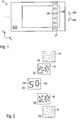
- FIG. 1 shows a schematic representation of a banknote 10 with an optically variable security element 12 according to the invention in the form of a wide security strip applied to the banknote substrate.
- the invention is not limited to security strips and bank notes, but can be used with all types of security elements, for example with labels on goods and Packaging or for securing documents, ID cards, passports, credit cards, health cards and the like.
- security threads or transfer elements can also be used, for example, in addition to security strips.
- the security strip 12 has a metallic appearance and, when viewed vertically, shows the number "50" spaced several times one above the other.
- Each representation of the value number “50” consists of two curve representations 14A, 14B, which are each formed from contiguous lines “5” and “0”, respectively.
- the curve representations 14A, 14B can be seen in a vertical plan view as light lines in front of the somewhat darker, but likewise shiny metallic background of the security strip 12. This visual impression when viewed vertically is in Fig. 2 (c) shown again in more detail.
- the security strip 12 shows an astonishing optical effect:
- Figures 2 (a) and (b) the appearance of the security element 12 with a tilt of 20 ° or 10 ° downwards (tilting direction 16A), while the Figures 2 (d) and (e) show the visual appearance with a tilt of 20 ° or 10 ° upwards (tilting direction 16B).
- Overall shows Fig. 2 for example five tilt positions with different visual impressions.
- Security elements often significantly more, for example 6 to 20 tilt positions with different visual impressions.
- Fig. 3 shows the curve representations 14A, 14B of the value number "50" with segments 18 somewhat separated from one another for illustration purposes
- Fig. 4 is a schematic plan view of a planar motif area 20, which is a section of the security element 12 of FIG Fig. 1 forms
- Fig. 5 two of the motion segments of Fig. 4 represents in detail and the Figures 6 and 7 each a cross-section through the flat motif area of Figures 4 and 5 along the lines VI-VI and VII-VII of the Fig. 5 demonstrate.
- each of the two output curves in the form of the digits “5” and “0” consists of several connected, non-collinear segments 18.
- Each of these segments 18 is a sub-area within the flat motif area 20 22, in which the segment 18 appears to move when the security element 12 is tilted and which is therefore referred to below as the movement segment 22.
- the movement segments 22 extend perpendicularly from the output curve essentially equally on both sides, the width of the segments advantageously being between 20% and 50% of the extension of the output curve.
- FIG. 12 also shows the output curves 14A and 14B, the connected segments of which lie in the center of the movement segments 22 in the exemplary embodiment.
- the planar motif area 20 contains a plurality of optically effective elements in the form of reflective facets 30, which in the exemplary embodiment have a base area of 15 ⁇ m ⁇ 15 ⁇ m and a maximum height of approximately 5 ⁇ m.
- the facets 30 are inclined at different angles in the y-direction, ie along the tilting directions 16A, 16B, and reflect incident light in a preferred direction which is given for each facet 30 by the condition "angle of incidence equals angle of reflection".
- angle of incidence equals angle of reflection
- the reverse is true for tilting a few degrees upwards in the tilting direction 16B.
- the segments 18 of the curve representation 14A visible in the movement segments 22A, 22B therefore run away from the initial curves in the opposite direction for the viewer when tilted and move away from one another.
- the occupation with optically variable elements described by way of example for the movement segments 22A, 22B is correspondingly also carried out for the other movement segments 22 of the surface region 20, so that the angles of inclination of the facets 30 in adjoining movement segments change in opposite ways.
- the segments 18 of the exit curves 14A, 14B run alternately in different directions for the viewer along the exit curves, so that the exit curves appear to disintegrate when the security element is tilted.
- orientation parameter k By using a general orientation parameter k , the shape of the movement segments and the movement behavior of the segments when tilted can be described independently of the actual implementation of the optically effective elements.
- the segments are separated from one another and show a representation of the disintegrated output curve.
- the orientation parameter k runs alternately either from -1 to +1 or from +1 to -1 within each of the movement segments 22.
- the orientation parameter in the movement segment 22A runs from the lower to the upper edge from -1 to +1, while in the adjacent movement segment 22B it runs from +1 to -1 from the lower to the upper edge. As in Fig. 8 shown this alternating course continues along the entire curve display.
- the facets of a planar motif area can be clearly described for a given size of the facets.
- a corresponding reflective surface area 20 can then be produced in a manner known per se, for example, by embossing the facets described in this way in an embossing lacquer layer and then metallizing.
- this angular range together with the angular spread of the movement range, defines a line width under which the initial curve and the disintegrating segments appear.
- the k values for a desired motif can be specified using suitable mathematical algorithms; the k value can, for example, increase proportionally to the distance between the segments and the starting curve. Alternatively, the values can also be generated manually by a designer, for example as a color gradient in a design sheet.
- the value of the orientation parameter preferably increases proportionally to the distance of a segment from the starting curve to the edge of the movement area to +1 or decreases to -1, as in the exemplary embodiment in FIG Fig. 8 shown.
- the relationship between the orientation parameter and the distance to the starting curve can of course also be non-linear.
- the line thickness or the dynamics of movement can be varied depending on the tilt angle.
- the k values can vary very widely around the k value of the output curve, so that a sharp representation of the output curve is achieved. To the edge The k value can then vary more slowly towards the movement segments, which increases the line width and increases the dynamics.
- the k value does not run through the entire range between -1 and +1 in all segments. If the k value in a segment only runs up to a k value of +0.5, for example, the segment appears to disappear when tilted into viewing angles that correspond to k values above 0.5, since then none are optically effective Elements are present that direct incident light towards the viewer at these viewing angles.
- microrelief structures with channel-shaped and / or rib-shaped structural elements can also be used as optically effective elements, as they are for example in the publication WO 2014/117938 A1 are described, the disclosure content of which is included in the present application.
- the orientation parameter k can be linked to the azimuth angle of the structural elements, for example.
- micro-lens or micro-concave mirror grids can also be used as optically effective elements which, together with line patterns, produce moiré magnification effects.
- the line patterns have approximately the same period as the microlens or micro-concave mirror rasters and are arranged approximately in the focal plane of the microlenses or micro-concave mirror.
- the microlenses or micro concave mirrors direct incident light in a direction depending on the viewing angle onto or next to the lines, so that they appear to a viewer either in the color of the lines or in the color of the spaces.
- the orientation parameter k indicates how far the line pattern is locally shifted with respect to the grid of the microlenses or micro-concave mirrors.
- the center point of the lines of the grid can be on a first edge of the individual microlenses or micro-concave mirrors and with a k value of +1 on a second edge of the microlenses or micro-concave mirrors opposite the first edge .
- the described movement effects can be generated not only when viewed from above, but also for viewing when viewed through. If, for example, the facets are not embedded in a material with the same or very similar refractive index, they act like small prisms when viewed through, so that differences in brightness result in the transmitted light and a movement effect according to the invention can be generated in transmitted light.
- a thin, semitransparent coating for example a thin metal layer
- the same embossed structures as reflective facets produce a movement effect according to the invention in plan view and at the same time with the effect of microprisms additionally a movement effect according to the invention in transparency.
- the above-mentioned microrelief structures and hologram grids can also be coated, for example, semitransparently, for example with a very thin metal layer, or with a highly refractive, transparent coating for viewing in transparency.
- the metallization is advantageously carried out with a thin metal film or a color-changing thin-film coating with the layer sequence reflector / dielectric / absorber.
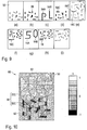
- FIGS. 9 and 10 illustrate a further embodiment of the invention, in which several curve representations are visible from different viewing directions as output curves with connected line segments.
- the security element in the exemplary embodiment has a metallic appearance in which the numerical value “50” is visible multiple times one above the other from a first viewing direction and the letter sequence “PL” from a second viewing direction.
- Figures 9 (a) to (i) illustrate the visual appearance of a section of a flat motif area 50, which shows as a motif on the one hand the disintegrating numerical value "50" and on the other hand the disintegrating letter sequence "PL", more precisely at different tilt angles.
- Figure 10 shows the values of the orientation parameter k for this exemplary embodiment in a gray level representation 60.
- the representation of the value number “50” contains the curve representations 14A, 14B already described in detail above in the form of the digits “5” and “0”, respectively.
- the representation of the letter sequence “PL” contains the curve representations 54A, 54B in the form of the letters “P” and “L”, respectively. Since the output curves in this embodiment cannot be seen from the same, but from different viewing directions should, the output curves are assigned to different values of the orientation parameter k . Specifically, the output curves for the number “50” correspond to a k value of +0.5 and the output curves for the lettering “PL” correspond to a k value of -0.5.
- movement segments 22 of the segments 18 of the value number "50” contain only k values between 0 and 1
- movement segments 52 of the segments 58 of the letter sequence "PL" only contain k values between -1 and 0, as in FIG Fig. 10 illustrated.
- the segments 18 of the value number "50" are only visible when tilted downwards, since the associated movement segments 22 do not contain any k values greater than 0.
- the segments 58 of the letter sequence “PL” are only visible when tilted upwards, since the associated movement segments 52 do not contain any k values less than 0.
- initially disordered segments 58 result in the letter sequence "PL”, which disintegrates again when tilting further, while other disordered segments 22 result in the value number "50”, which in turn disintegrates when tilting further upwards ( Figures 9 (a) to (i) ). When tilting back, the movement is reversed.
- the movement segments 22, 52 and the segments 18, 58 of the two partial representations are particularly advantageously coordinated with one another in such a way that individual segments run continuously from motion segments of the first representation into motion segments of the second representation.
- the overall representation then contains a common range of motion in which one or more segments move in such a way that they are part of the first representation from the first viewing directions and part of the second representation from the second viewing directions. In this way, the visual impression can be generated that segments of the disintegrating first representation are reassembled to form the new second representation.
Description
Die Erfindung betrifft ein optisch variables Sicherheitselement zur Absicherung von Wertgegenständen, ein Verfahren zur Herstellung eines solchen Sicherheitselements und einen entsprechend ausgestatteten Datenträger.The invention relates to an optically variable security element for protecting objects of value, a method for producing such a security element and a correspondingly equipped data carrier.
Datenträger, wie etwa Wert- oder Ausweisdokumente, oder andere Wertgegenstände, wie etwa Markenartikel, werden zur Absicherung oft mit Sicherheitselementen versehen, die eine Überprüfung der Echtheit der Datenträger gestatten und die zugleich als Schutz vor unerlaubter Reproduktion dienen. Eine besondere Rolle bei der Echtheitsabsicherung spielen Sicherheitselemente mit betrachtungswinkelabhängigen Effekten, da diese selbst mit modernsten Kopiergeräten nicht reproduziert werden können. Die Sicherheitselemente werden dabei mit optisch variablen Elementen ausgestattet, die dem Betrachter unter unterschiedlichen Betrachtungswinkeln einen unterschiedlichen Bildeindruck vermitteln und beispielsweise je nach Betrachtungswinkel einen anderen Farb- oder Helligkeitseindruck und/oder ein anderes graphisches Motiv zeigen.Data carriers, such as value or identity documents, or other objects of value, such as branded items, are often provided with security elements for protection that allow the authenticity of the data carrier to be checked and at the same time serve as protection against unauthorized reproduction. Security elements with viewing angle-dependent effects play a special role in securing authenticity, since these cannot be reproduced even with the most modern copiers. The security elements are equipped with optically variable elements which give the viewer a different image impression from different viewing angles and, for example, show a different color or brightness impression and / or a different graphic motif depending on the viewing angle.
In diesem Zusammenhang sind optisch variable Sicherheitselemente bekannt, die beim Kippen des Sicherheitselements verschiedene Bewegungs- oder Kippeffekte zeigen, wie etwa bewegte Balken, bewegte bildliche Darstellungen, Pumpeffekte oder dreidimensionale Darstellungen. Zur Umsetzung der optisch variablen Erscheinungsbilder werden im Stand der Technik unterschiedliche Techniken eingesetzt, mit denen sich typischerweise manche dieser Bewegungseffekte besonders gut und andere weniger gut realisieren lassen.In this context, optically variable security elements are known which, when the security element is tilted, show various movement or tilting effects, such as moving bars, moving pictorial representations, pumping effects or three-dimensional representations. To implement the optically variable appearances, different techniques are used in the prior art, with which some of these movement effects can typically be implemented particularly well and others less well.
Beispielsweise können mit Moiré-Vergrößerungsanordnungen auf der Basis von Mikrofokussierelementen und Mikrobildern vor allem bewegte periodische Motive gut dargestellt werden. Dagegen sind Kippbilder oder Darstellungen mit einer ausgezeichneten Mittelstellung, also einer Ansicht, die bei gleichem Betrachtungswinkel bei allen produzierten Sicherheitselementen immer gleich aussieht, wegen der erforderlichen hochgenauen Registrierung der Mikrofokussierelemente und Mikrobilder oft schwierig zu realisieren.For example, with moiré magnification arrangements based on microfocusing elements and microimages, especially moving periodic Motifs are well represented. On the other hand, tilt images or representations with an excellent center position, i.e. a view that always looks the same for all security elements produced at the same viewing angle, are often difficult to realize because of the high-precision registration of the microfocusing elements and microimages required.
Hologramme können durch ineinander verschachtelte Darstellungen, die unter verschiedenen Kippwinkeln sichtbar werden, grundsätzlich beliebige Animationen zeigen, allerdings ist die Qualität und Leuchtkraft der Darstellungen stark von einer guten Beleuchtung abhängig. Ähnliches gilt für Sicherheitselemente mit Mikrospiegelanordnungen, wenn die verschiedenen Ansichten einer Animation dort ineinander verschachtelt werden sollen, auch wenn Mikrospiegelanordnungen in der Regel lichtstärker sind als Hologramme.Holograms can basically show any animation through nested representations that are visible at different tilt angles, but the quality and luminosity of the representations are heavily dependent on good lighting. The same applies to security elements with micromirror arrangements if the different views of an animation are to be nested in one another there, even if micromirror arrangements are generally more luminous than holograms.
Aus der Druckschrift
Die Druckschrift
Bei optisch variablen Sicherheitsmerkmalen auf der Basis von Druckfarben mit magnetisch ausgerichteten reflektierenden Pigmenten sind die erzeugten Effekte sehr lichtstark, zur Realisierung eines bestimmten Bewegungseffekts werden allerdings immer auch entsprechende Magnete zur Ausrichtung der Pigmente benötigt, was die Effektvielfalt und die Auflösung in der Praxis stark einschränkt.In the case of optically variable security features based on printing inks with magnetically aligned reflective pigments, the effects generated are very bright, but to achieve a certain movement effect, appropriate magnets are always required to align the pigments, which in practice severely limits the variety of effects and resolution.
Die genannten optisch variablen Effekte lassen sich oft nur schwer individualisieren, das heißt, beispielsweise auf eine bestimmte Währung oder eine bestimmte Wertzahl abstimmen. Eine verbreitete Möglichkeit der Individualisierung besteht in einer bereichsweisen Demetallisierung, bei der eine Effektschicht bereichsweise etwa in Form einer Wertzahl ausgespart wird. Solche Negativtexte sind jedoch vergleichsweise unauffällig, wodurch die Gefahr steigt, dass ein Fälscher beispielsweise ein echtes Sicherheitselement aus einer Banknote mit niedrigem Wert zur Fälschung einer Banknote mit höherem Wert verwendet, ohne dass es dem ungeschulten oder flüchtigen Betrachter auffällt.The optically variable effects mentioned are often difficult to individualize, that is to say, for example, they can be adapted to a specific currency or a specific value. A widespread possibility of individualization is demetallization in certain areas, in which an effect layer is left out in some areas, for example in the form of a number. Such negative texts are, however, comparatively inconspicuous, which increases the risk that a forger will, for example, misuse a genuine security element of a lower denomination banknote is used to counterfeit a higher denomination banknote without the untrained or casual observer noticing.
Ausgehend davon liegt der Erfindung die Aufgabe zugrunde, ein Sicherheitselement der eingangs genannten Art anzugeben, das einen neuartigen und sich von herkömmlichen Effekten deutlich abhebenden optisch variablen Effekt zeigt. Idealerweise ermöglicht der optisch variable Effekt auch eine auffällige und gut einprägbare Individualisierung des Sicherheitselements bzw. des damit versehenen Datenträgers.Proceeding from this, the invention is based on the object of specifying a security element of the type mentioned at the outset which exhibits a novel, optically variable effect that clearly stands out from conventional effects. Ideally, the optically variable effect also enables a conspicuous and easily memorable individualization of the security element or of the data carrier provided with it.
Diese Aufgabe wird durch die Merkmale der unabhängigen Ansprüche gelöst. Weiterbildungen der Erfindung sind Gegenstand der abhängigen Ansprüche.This object is achieved by the features of the independent claims. Developments of the invention are the subject of the dependent claims.
Gemäß der Erfindung zeigt ein gattungsgemäßes Sicherheitselement betrachtungswinkelabhängig ein Motiv mit zumindest einer Kurvendarstellung, die aus einer ersten Betrachtungsrichtung als Ausgangskurve mit zwei oder mehr zusammenhängenden, nicht kollinearen Segmenten sichtbar ist, und die beim Kippen des Sicherheitselements um eine vorbestimmte Achse in die einzelnen Segmente zerfällt, indem sich die Segmente der Ausgangskurve abwechselnd in unterschiedliche Richtungen von der Ausgangskurve weg bewegen.According to the invention, a generic security element shows, depending on the viewing angle, a motif with at least one curve representation, which is visible from a first viewing direction as an output curve with two or more contiguous, non-collinear segments, and which breaks down into the individual segments when the security element is tilted about a predetermined axis, in that the segments of the exit curve move alternately in different directions away from the exit curve.
Erfindungsgemäß weist das Sicherheitselement dabei einen flächigen Motivbereich mit einer Mehrzahl optisch wirksamer Elemente auf, die einfallendes Licht jeweils in eine Vorzugsrichtung lenken, wobei den Segmenten der Ausgangskurve in dem flächigen Motivbereich jeweils ein Bewegungssegment in Form eines Teilbereichs des flächigen Motivbereichs zugeordnet ist, in dem die optisch wirksamen Elemente so angeordnet und ausgerichtet sind, dass sie aus der ersten Betrachtungsrichtung die Ausgangskurve mit den zusammenhängenden Segmenten zeigen, und dass sie aus um die vorbestimmte Achse gekippten Betrachtungsrichtungen Kurvendarstellungen zeigen, in denen die Segmente abwechselnd in unterschiedliche Richtungen und mit zunehmendem Kippwinkel zunehmend weiter von der Ausgangskurve entfernt liegen.According to the invention, the security element has a planar motif area with a plurality of optically effective elements which each direct incident light in a preferred direction, the segments of the output curve in the planar motif area being assigned a movement segment in the form of a sub-area of the planar motif area, in which the optically effective elements are arranged and aligned in such a way that they show the starting curve with the connected segments from the first viewing direction, and that they show curve representations from the viewing directions tilted about the predetermined axis in which the segments alternate in different directions and with increasing Tilt angle are increasingly further away from the starting curve.
Die zusammenhängenden Segmente der Ausgangskurve sind nicht kollinear, das heißt, sie liegen nicht alle auf einer Geraden. So liegen zumindest zwei der zusammenhängenden Segmente der Ausgangskurve nicht auf einer Geraden. Dies schließt auch nicht aus, dass voneinander beabstandete Segmente parallel zueinander sind, wie etwa die beiden durch die Diagonale verbundenen Deckstriche des Buchstabens "Z".The connected segments of the output curve are not collinear, that is, they do not all lie on a straight line. At least two of the connected segments of the starting curve are not on a straight line. This also does not rule out that segments spaced apart from one another are parallel to one another, such as the two cover lines of the letter "Z" connected by the diagonal.
Bevorzugt zerfällt zumindest eine Kurvendarstellung des Motivs beim Kippen des Sicherheitselements in drei oder mehr, vorzugsweise vier oder mehr, oder sogar sechs oder mehr Segmente. Da sich die Segmente beim Kippen des Sicherheitselements abwechselnd in unterschiedliche Richtungen von der Ausgangskurve weg bewegen, sind die bewegten Segmente nicht mehr zusammenhängend aber zunächst noch benachbart, so dass der visuelle Eindruck einer in die einzelnen Segmente zerfallenden Kurve entsteht.At least one curve representation of the motif preferably breaks down into three or more, preferably four or more, or even six or more segments when the security element is tilted. Since the segments move alternately in different directions away from the starting curve when the security element is tilted, the moving segments are no longer contiguous but are initially still adjacent, so that the visual impression of a curve breaking up into the individual segments is created.
Die Ausgangskurve zumindest einer Kurvendarstellung zeigt mit Vorteil ein alphanumerisches Zeichen, ein Symbol, wie etwa das Eurosymbol oder ein anderes Währungssymbol, oder ein anderes informationstragendes Zeichen. Insbesondere können auch zwei oder mehr Ausgangskurven vorgesehen sein, die zusammen eine Zahl, wie etwa Wertzahl einer Banknote, eine Buchstabenfolge oder eine Symbolfolge bilden.The output curve of at least one curve display advantageously shows an alphanumeric character, a symbol, such as the euro symbol or another currency symbol, or another information-carrying character. In particular, two or more output curves can also be provided which together form a number, such as a banknote's value number, a sequence of letters or a sequence of symbols.
Die Bewegungssegmente der Kurvendarstellungen weisen vorteilhaft eine Breite auf, die zwischen 10% und 100%, vorzugsweise zwischen 20% und 50% der Ausdehnung der Ausgangskurve der Kurvendarstellung liegt. Als Breite der Bewegungssegmente wird dabei die Ausdehnung der Bewegungssegmente senkrecht zu dem zugehörigen Segment der Ausgangskurve bezeichnet. Innerhalb einer Kurvendarstellung weisen die Bewegungssegmente mit Vorteil alle dieselbe Breite auf.The movement segments of the curve representations advantageously have a width that is between 10% and 100%, preferably between 20% and 50% of the extent of the initial curve of the curve representation. The extension of the movement segments perpendicular to the associated segment of the starting curve is referred to as the width of the movement segments. Within a curve display, the movement segments advantageously all have the same width.
Die optisch wirksamen Elemente lenken einfallendes Licht jeweils in eine Vorzugsrichtung, wobei der Mechanismus der Lichtablenkung von der Art der optisch wirksamen Elemente abhängt. Beispielsweise können die optisch wirksamen Elemente reflektierende Facetten sein, die kleine Mikrospiegel bilden, die einfallendes Licht in eine durch die Bedingung "Einfallswinkel gleich Ausfallswinkel" gegebene Vorzugsrichtung lenken. Neben Reflexion kommt insbesondere auch Lichtbrechung, beispielsweise durch Linsenelemente oder Prismenelemente, oder Lichtbeugung, beispielsweise durch Hologrammgitterbereiche in Betracht. Die Lichtablenkung durch die optisch wirksamen Elemente kann in Reflexion, in Transmission oder sowohl in Reflexion als auch in Transmission erfolgen.The optically effective elements each direct incident light in a preferred direction, the mechanism of light deflection depending on the type of optically effective elements. For example, the optically effective elements can be reflective facets that form small micromirrors that direct incident light in a preferred direction given by the condition “angle of incidence equals angle of reflection”. In addition to reflection, light refraction, for example by lens elements or prism elements, or light diffraction, for example by hologram grating areas, can also be considered. The light deflection by the optically effective elements can take place in reflection, in transmission or both in reflection and in transmission.
In einer vorteilhaften Erfindungsvariante sind die optisch wirksamen Elemente durch strahlungsoptisch wirkende Facetten gebildet, deren Orientierung jeweils durch einen Neigungswinkel α gegen die Ebene des flächigen Motivbereichs und durch einen Azimutwinkel θ in der Ebene des flächigen Motivbereichs charakterisiert ist. Die Abmessung der Facetten ist dabei vorzugweise so groß, dass keine oder kaum Beugungseffekte auftreten, so dass die Facetten im Wesentlichen nur strahlungsoptisch wirken. Insbesondere weisen die Facetten mit Vorteil eine kleinste Abmessung von mehr als 2 µm, vorzugsweise von mehr als 5 µm, insbesondere von mehr als 10 µm auf. Insbesondere für die Anwendung bei Banknoten und anderen Wertdokumenten weisen die Facetten bevorzugt eine Höhe unterhalb von 100 µm, bevorzugt unterhalb von 50 µm, insbesondere von weniger als 10 µm auf. Die Facetten können regelmäßig, beispielsweise in Form eines 1- oder 2-dimensionalen periodischen Rasters, etwa eines Sägezahngitters, oder auch aperiodisch angeordnet sein.In an advantageous variant of the invention, the optically effective elements are formed by radiation-optically acting facets, the orientation of which is characterized by an angle of inclination α relative to the plane of the flat motif area and an azimuth angle θ in the plane of the flat motif area. The dimensions of the facets are preferably so large that no or hardly any diffraction effects occur, so that the facets essentially only have a radiation-optical effect. In particular, the facets advantageously have a smallest dimension of more than 2 µm, preferably of more than 5 μm, in particular of more than 10 μm. In particular for use in bank notes and other documents of value, the facets preferably have a height of less than 100 μm, preferably less than 50 μm, in particular less than 10 μm. The facets can be arranged regularly, for example in the form of a 1- or 2-dimensional periodic grid, for example a sawtooth grid, or else aperiodically.
Die optisch wirksamen Elemente können auch mit Vorteil durch beugungsoptisch wirkende Gitterfelder mit einem Gittermuster aus parallelen Strichgitterlinien gebildet sein. Die Vorzugsrichtung der Lichtablenkung ist dabei durch die Gitterparameter des Gittermusters gegeben, insbesondere durch die Gitterperiode p und den Azimutwinkel ϕ, welcher den Winkel angibt, den die Strichgitterlinien des Gittermusters mit einer Referenzrichtung einschließen.The optically active elements can also advantageously be formed by diffraction-optically acting grating fields with a grating pattern made up of parallel grating lines. The preferred direction of the light deflection is given by the grating parameters of the grating pattern, in particular by the grating period p and the azimuth angle ϕ, which specifies the angle that the grating lines of the grating pattern enclose with a reference direction.
In einer weiteren vorteilhaften Erfindungsvariante sind die optisch wirksamen Elemente durch rinnen- und/oder rippenförmige, nebeneinander liegende und sich längs einer Längsrichtung erstreckende Strukturelemente gebildet, wie sie beispielsweise in der Druckschrift
Der flächige Motivbereich kann reflektierend ausgebildet sein, so dass die Ausgangskurve und der Zerfall der Ausgangskurve in einzelne Segmente in Reflexion sichtbar sind.The flat motif area can be designed to be reflective, so that the output curve and the breakdown of the output curve into individual segments are visible in reflection.
In vorteilhaften Gestaltungen sind die optisch wirksamen Elemente durch Reflexionselemente gebildet, die in einen Prägelack abgeformt und mit einer reflexionserhöhenden Beschichtung versehen sind. Die reflexionserhöhende Beschichtung kann durch eine Metallisierung gebildet sein und/oder kann einen Farbkippeffekt aufweisen, in welchem Fall die Beschichtung mit Vorteil aus einem Dünnfilminterferenzschichtsystem mit Reflektor, dielektrischer Abstandsschicht und Absorber besteht.In advantageous configurations, the optically effective elements are formed by reflection elements that are molded into an embossing lacquer and with a reflection-increasing coating are provided. The reflection-increasing coating can be formed by a metallization and / or can have a color shift effect, in which case the coating advantageously consists of a thin film interference layer system with reflector, dielectric spacer layer and absorber.
Der flächige Motivbereich kann auch zumindest teilweise transmittierend sein, so dass die Ausgangskurve und der Zerfall der Ausgangskurve in einzelne Segmente in Transmission sichtbar sind. Dabei kann der flächige Motivbereich auch sowohl teilweise reflektierend als auch teilweise transmittierend ausgebildet sein, so dass die Ausgangskurve und der Zerfall der Ausgangskurve in einzelne Segmente sowohl in Reflexion als auch in Transmission sichtbar sind.The flat motif area can also be at least partially transmitting, so that the output curve and the breakdown of the output curve into individual segments are visible in transmission. The flat motif area can also be designed to be partially reflective as well as partially transmissive, so that the output curve and the breakdown of the output curve into individual segments are visible both in reflection and in transmission.
In vorteilhaften Gestaltungen sind die optisch wirksamen Elemente durch Transmissionselemente in Form transparenter oder semitransparenter Beugungsstrukturen, transparenter oder semitransparenter Prismenstrukturen oder transparenter oder semitransparenter Mikroreliefstrukturen gebildet. Wie oben bereits erwähnt, können die Transmissionselemente zugleich reflektierende Eigenschaften haben und damit einen zusätzlichen Bewegungseffekt in Reflexion erzeugen.In advantageous designs, the optically effective elements are formed by transmission elements in the form of transparent or semitransparent diffraction structures, transparent or semitransparent prismatic structures or transparent or semitransparent micro-relief structures. As already mentioned above, the transmission elements can at the same time have reflective properties and thus generate an additional movement effect in reflection.
In einer vorteilhaften Weiterbildung der Erfindung ist vorgesehen, dass das Motiv des Sicherheitselements zumindest eine zweite Kurvendarstellung enthält, die aus einer zweiten Betrachtungsrichtung als zweite Ausgangskurve mit zwei oder mehr zusammenhängenden, nicht kollinearen Segmenten sichtbar ist, und die beim Kippen des Sicherheitselements um die vorbestimmte Achse in die einzelnen Segmente zerfällt, indem sich die Segmente der zweiten Ausgangskurve abwechselnd in unterschiedliche Richtungen von der zweiten Ausgangskurve weg bewegen, wobei den Segmenten der zweiten Ausgangskurve in dem flächigen Motivbereich jeweils ein zweites Bewegungssegment in Form eines Teilbereichs des flächigen Motivbereichs zugeordnet ist, in dem die optisch wirksamen Elemente so angeordnet und ausgerichtet sind, dass sie aus der zweiten Betrachtungsrichtung die zweite Ausgangskurve mit den zusammenhängenden Segmenten zeigen, und dass sie aus um die vorbestimmte Achse gekippten Betrachtungsrichtungen Kurvendarstellungen zeigen, in denen die Segmente abwechselnd in unterschiedliche Richtungen und mit zunehmendem Kippwinkel zunehmend weiter von der zweiten Ausgangskurve entfernt liegen.In an advantageous development of the invention it is provided that the motif of the security element contains at least one second curve representation, which is visible from a second viewing direction as a second output curve with two or more contiguous, non-collinear segments, and which is visible when the security element is tilted around the predetermined axis is broken down into the individual segments in that the segments of the second output curve alternate in different directions move away from the second output curve, the segments of the second output curve in the planar motif area each being assigned a second movement segment in the form of a sub-area of the planar motif area in which the optically effective elements are arranged and aligned so that they are the show second output curve with the connected segments, and that they show curve representations from viewing directions tilted about the predetermined axis, in which the segments are located alternately in different directions and increasingly further away from the second output curve as the tilt angle increases.
In einer vorteilhaften Erfindungsvariante überlappen die Bewegungssegmente der ersten und zweiten Kurvendarstellung dabei nicht.In an advantageous variant of the invention, the movement segments of the first and second curve display do not overlap.
Um eine große visuelle Trennung der beiden Kurvendarstellungen bei der Betrachtung zu erreichen, schließen die erste und zweite Betrachtungsrichtung mit Vorteil einen Winkel von mindestens 5°, bevorzugt mindestens 10° und besonders bevorzugt mindestens 20° ein.In order to achieve a large visual separation of the two curve representations when viewing, the first and second viewing directions advantageously enclose an angle of at least 5 °, preferably at least 10 ° and particularly preferably at least 20 °.
In einer vorteilhaften Erfindungsvariante ist mindestens ein Segment der ersten Kurvendarstellung auch ein Segment der zweiten Kurvendarstellung, so dass sich die zweite Kurvendarstellung beim Kippen des Sicherheitselements zumindest teilweise aus Segmenten der zerfallenen ersten Kurvendarstellung zusammensetzt.In an advantageous variant of the invention, at least one segment of the first curve display is also a segment of the second curve display, so that when the security element is tilted, the second curve display is composed at least partially of segments of the disintegrated first curve display.
Es versteht sich, dass das Motiv des Sicherheitselements in gleicher Weise auch mehr als zwei Kurvendarstellungen enthalten kann, die aus unterschiedlichen Betrachtungsrichtungen als zusammenhängende Ausgangskurven sichtbar sind.It goes without saying that the motif of the security element can in the same way also contain more than two curve representations, which are visible from different viewing directions as coherent output curves.
Das Sicherheitselement stellt mit Vorteil einen Sicherheitsfaden, einen Aufreißfaden, ein Sicherheitsband, einen Sicherheitsstreifen, einen Patch oder ein Etikett zum Aufbringen auf ein Sicherheitspapier, Wertdokument oder dergleichen dar.The security element advantageously represents a security thread, a tear-open thread, a security tape, a security strip, a patch or a label for application to a security paper, document of value or the like.
Die Erfindung enthält auch einen Datenträger mit einem Sicherheitselement der beschriebenen Art, wobei das Sicherheitselement sowohl in einem opaken Bereich des Datenträgers als auch in oder über einem transparenten Fensterbereich oder einer durchgehenden Öffnung des Datenträgers angeordnet sein kann. Bei dem Datenträger kann es sich insbesondere um ein Wertdokument, wie eine Banknote, insbesondere eine Papierbanknote, eine Polymerbanknote oder eine Folienverbundbanknote, um eine Aktie, eine Anleihe, eine Urkunde, einen Gutschein, einen Scheck, eine hochwertige Eintrittskarte, aber auch um eine Ausweiskarte, wie etwa eine Kreditkarte, eine Bankkarte, eine Barzahlungskarte, eine Berechtigungskarte, einen Personalausweis oder eine Passpersonalisierungsseite handeln.The invention also contains a data carrier with a security element of the type described, wherein the security element can be arranged both in an opaque area of the data carrier and in or above a transparent window area or a continuous opening of the data carrier. The data carrier can in particular be a value document, such as a bank note, in particular a paper bank note, a polymer bank note or a film composite bank note, a share, a bond, a certificate, a voucher, a check, a high-quality admission ticket, but also an identity card such as a credit card, a bank card, a cash card, an authorization card, an identity card or a passport personalization page.
Die Erfindung enthält weiter ein Verfahren zur Herstellung eines optisch variablen Sicherheitselements der oben beschriebenen Art, bei dem
- eine gewünschte Ausgangskurve mit zwei oder mehr zusammenhängenden, nicht kollinearen Segmenten festgelegt wird,
- für die Segmente der Ausgangskurve jeweils Bewegungssegmente festgelegt werden, in denen sich die Segmente der Ausgangskurve beim Kippen des Sicherheitselements bewegen, und
- in einem flächigen Motivbereich in den festgelegten Bewegungssegmenten optisch wirksame Elemente so angeordnet und ausgerichtet werden, dass sie aus der ersten Betrachtungsrichtung die Ausgangskurve mit den zusammenhängenden Segmenten zeigen, und dass sie aus um die vorbestimmte Achse gekippten Betrachtungsrichtungen Kurvendarstellungen zeigen, in denen die Segmente abwechselnd in unterschiedliche Richtungen und mit zunehmendem Kippwinkel zunehmend weiter von der Ausgangskurve entfernt liegen.
- a desired output curve with two or more connected, non-collinear segments is determined,
- Movement segments in which the segments of the output curve move when the safety element is tilted are defined for the segments of the exit curve, and
- optically effective elements are arranged and aligned in a flat motif area in the defined movement segments in such a way that they show the starting curve with the connected segments from the first viewing direction, and that they show curve representations from viewing directions tilted about the predetermined axis in which the segments alternate in different directions and with increasing tilt angle are increasingly further away from the starting curve.
Weitere Ausführungsbeispiele sowie Vorteile der Erfindung werden nachfolgend anhand der Figuren erläutert, bei deren Darstellung auf eine maßstabs- und proportionsgetreue Wiedergabe verzichtet wurde, um die Anschaulichkeit zu erhöhen.Further exemplary embodiments as well as advantages of the invention are explained below with reference to the figures, in the representation of which a reproduction true to scale and proportion was dispensed with in order to increase the clarity.
Es zeigen:
- Fig. 1
- eine schematische Darstellung einer Banknote mit einem erfindungsgemäßen optisch variablen Sicherheitselement,
- Fig. 2
- in (a) bis (e) das Erscheinungsbild des optisch variablen Sicherheitselements der
Fig. 1 bei verschiedenen Kippwinkeln zwischen -20° und +20°, - Fig. 3
- die Kurvendarstellungen der Ziffern "5" und "0" der Wertzahl "50" der
Fig. 1 mit zur Illustration voneinander abgesetzten Segmenten, - Fig. 4
- eine schematische Aufsicht auf einen flächigen Motivbereich, der als Ausschnitt des Sicherheitselements der
Fig. 1 eine Darstellung der Wertzahl "50" zeigt, - Fig. 5
- schematisch zwei der Bewegungssegmente der Ziffer "5" der
Fig. 4 im Detail, - Fig. 6 und 7
- jeweils einen schematischen Querschnitt durch den flächigen Motivbereich der
Figuren 4 bzw. 5 entlang der Linien VI-VI bzw. VII-VII, - Fig. 8
- die Werte des Orientierungsparameters k für das Ausführungsbeispiel der zerfallenden Wertzahl "50" in einer Graustufendarstellung,
- Fig. 9
- in (a) bis (i) das visuelle Erscheinungsbild eines Sicherheitselements nach einem weiteren Ausführungsbeispiel der Erfindung bei verschiedenen Kippwinkeln, und
- Fig. 10
- die Werte des Orientierungsparameters k für das Ausführungsbeispiel der
Fig. 9 in Graustufendarstellung.
- Fig. 1
- a schematic representation of a bank note with an optically variable security element according to the invention,
- Fig. 2
- in (a) to (e) the appearance of the optically variable security element of
Fig. 1 at different tilt angles between -20 ° and + 20 °, - Fig. 3
- the graphs of the digits "5" and "0" of the value number "50" of the
Fig. 1 with segments separated from one another for illustration purposes, - Fig. 4
- a schematic plan view of a flat motif area, which is used as a section of the security element of
Fig. 1 shows a representation of the value number "50", - Fig. 5
- schematically two of the movement segments of the number "5" of the
Fig. 4 in detail, - Figures 6 and 7
- each a schematic cross section through the planar motif area of
Figures 4 or 5 along the lines VI-VI or VII-VII, - Fig. 8
- the values of the orientation parameter k for the exemplary embodiment of the decaying value number "50" in a gray scale representation,
- Fig. 9
- in (a) to (i) the visual appearance of a security element according to a further exemplary embodiment of the invention at different tilt angles, and
- Fig. 10
- the values of the orientation parameter k for the embodiment of FIG
Fig. 9 in grayscale display.
Die Erfindung wird nun am Beispiel von Sicherheitselementen für Banknoten erläutert.
Der Sicherheitsstreifen 12 weist ein metallisches Erscheinungsbild auf und zeigt bei senkrechter Aufsicht die Wertzahl "50" beabstandet mehrfach übereinander. Jede Darstellung der Wertzahl "50" besteht aus zwei Kurvendarstellungen 14A, 14B, die jeweils aus zusammenhängenden Linienzügen "5" bzw. "0" gebildet sind. Die Kurvendarstellungen 14A, 14B sind in senkrechter Aufsicht als helle Linienzüge vor dem etwas dunkleren, aber ebenfalls metallisch glänzenden Hintergrund des Sicherheitsstreifens 12 erkennbar. Dieser visuelle Eindruck bei senkrechter Aufsicht ist in
Beim Kippen 16A, 16B der Banknote 10 um ihre Längsachse zeigt der Sicherheitsstreifen 12 einen verblüffenden optischen Effekt: Die ursprünglich zusammenhängenden Kurvendarstellungen 14A, 14B, nachfolgend auch oft als Ausgangskurven bezeichnet, zerfallen für den Betrachter in eine Mehrzahl einzelner Segmente 18, welche sich mit zunehmender Verkippung abwechselnd in unterschiedliche Richtungen von der jeweiligen Ausgangskurve weg bewegen.When the
Zur Illustration zeigen die
Ausgehend von der zusammenhängenden Darstellung der Ausgangskurven 14A, 14B in
Das Zustandekommen dieses verblüffenden Zerfallseffekts wird nun anhand der
Wie in den Kurvendarstellungen 14A, 14B der
Die Bewegungssegmente 22 erstrecken sich von der Ausgangskurve senkrecht im Wesentlichen gleich weit auf beide Seiten, wobei die Breite der Segmente mit Vorteil zwischen 20% und 50% der Ausdehnung der Ausgangskurve liegt.
Wie im Detailausschnitt der
Die jeweils in der Mitte der Bewegungssegmente 22A und 22B angeordneten Facetten 32 weisen dabei einen Neigungswinkel α = 0° gegen die Ebene des flächigen Motivbereichs 20 auf und reflektieren daher bei senkrechtem Lichteinfall im Wesentlichen senkrecht nach oben. Die im Bewegungssegment 22A von den Facetten 32 in +y-Richtung versetzten Facetten 34 weisen zunehmende Neigungswinkel α bis hin zu einem Neigungswinkel α = +20° am oberen Rand 24-O des Bewegungssegments auf, währen die in -y-Richtung versetzten Facetten 36 abnehmende Neigungswinkel α bis hin zu einem Neigungswinkel α = -20° am unteren Rand 24-U des Bewegungssegments aufweisen.The
Im unmittelbar angrenzenden Bewegungssegment 22B ändern sich die Neigungswinkel der Facetten in umgekehrter Weise, das heißt, ausgehend von den in der Mitte mit einem einen Kippwinkel α = 0° angeordneten Facetten weisen die in +y-Richtung versetzten Facetten 36 abnehmende Neigungswinkel α bis hin zu einem Neigungswinkel α = -20° am oberen Rand 26-O des Bewegungssegments 22B auf, während die in -y-Richtung versetzten Facetten 34 zunehmende Neigungswinkel α bis hin zu einem Neigungswinkel α = +20° am unteren Rand 26-U des Bewegungssegments 22B aufweisen.In the immediately
Wird nun das Sicherheitselement 12 mit dem Flächenbereich 20 ausgehend von senkrechter Aufsicht um einige Grad nach unten (Kipprichtung 16A) verkippt, so ist die Reflexionsbedingung "Einfallswinkel gleich Ausfallswinkel" im Bewegungssegment 22A für nach oben (in +y-Richtung) versetzte Facetten 34 und im Bewegungssegment 22B für nach unten (in -y-Richtung) versetzte Facetten 34 erfüllt. Umgekehrtes gilt für eine Verkippung um einige Grad nach oben in Kipprichtung 16B. Die in den Bewegungssegmenten 22A, 22B sichtbaren Segmente 18 der Kurvendarstellung 14A laufen für den Betrachter daher beim Kippen in entgegengesetzte Richtung von den Ausgangskurven weg und entfernen sich voneinander.If the security element 12 with the
Die für die Bewegungssegmente 22A, 22B beispielhafte beschriebene Belegung mit optisch variablen Elementen wird entsprechend auch für die anderen Bewegungssegmente 22 des Flächenbereichs 20 vorgenommen, so dass sich die Neigungswinkel der Facetten 30 in aneinandergrenzenden Bewegungssegmenten jeweils in entgegengesetzter Weise ändern. Auf diese Weise laufen die Segmente 18 der Ausgangskurven 14A, 14B für den Betrachter entlang der Ausgangskurven jeweils abwechselnd in unterschiedliche Richtungen, so dass die Ausgangskurven beim Kippen des Sicherheitselements zu zerfallen scheinen.The occupation with optically variable elements described by way of example for the
Im Ausführungsbeispiel der
Zur Illustration zeigt
Im Ausführungsbeispiel läuft der Orientierungsparameter k innerhalb jedes der Bewegungssegmente 22 alternierend entweder von -1 zu +1 oder von +1 zu -1. Beispielsweise läuft der Orientierungsparameter im Bewegungssegment 22A vom unteren zum oberen Rand von -1 zu +1, während er im angrenzenden Bewegungssegment 22B vom unteren zum oberen Rand von +1 zu -1 läuft. Wie in
Bei der Umsetzung der optisch wirksamen Elemente durch die Facetten 30 wurde der Neigungswinkel der Facetten in y-Richtung durch die Beziehung ![]()
![]()
Durch eine zweidimensionale Vorgabe des Orientierungsparameters k wie in
Zurückkommend auf die Darstellung der ![]()
![]()
Die Vorgabe der k-Werte für ein gewünschtes Motiv kann über geeignete mathematische Algorithmen erfolgen, der k-Wert kann beispielsweise proportional zum Abstand der Segmente von der Ausgangskurve anwachsen. Alternativ können die Werte auch per Hand von einem Designer etwa als Farbverlauf in einem Designblatt erzeugt werden. Bevorzugt steigt der Wert des Orientierungsparameters proportional zum Abstand eines Segmentes von der Ausgangskurve zum Rand des Bewegungsbereichs auf +1 an bzw. fällt auf -1 ab, wie etwa im Ausführungsbeispiel der
Grundsätzlich kann der Zusammenhang zwischen dem Orientierungsparameter und dem Abstand zur Ausgangskurve natürlich auch nicht-linear sein. Dadurch kann insbesondere die Strichstärke oder die Bewegungsdynamik abhängig vom Kippwinkel variiert werden. Beispielsweise können die k-Werte um den k-Wert der Ausgangskurve herum sehr stark variieren, so dass eine scharfe Darstellung der Ausgangskurve erreicht wird. Zum Rand der Bewegungssegmente hin kann der k-Wert dann langsamer variieren, wodurch die Strichstärke größer wird und die Dynamik zunimmt.In principle, the relationship between the orientation parameter and the distance to the starting curve can of course also be non-linear. As a result, the line thickness or the dynamics of movement can be varied depending on the tilt angle. For example, the k values can vary very widely around the k value of the output curve, so that a sharp representation of the output curve is achieved. To the edge The k value can then vary more slowly towards the movement segments, which increases the line width and increases the dynamics.
In manchen Ausgestaltungen kann auch vorgesehen sein, dass der k-Wert nicht in allen Segmenten den gesamten Bereich zwischen -1 und +1 durchläuft. Läuft der k-Wert in einem Segment beispielsweise nur bis zu einem k-Wert von +0,5, so scheint das Segment beim Kippen in Betrachtungswinkel, die k-Werten oberhalb von 0,5 entsprechen, zu verschwinden, da dann keine optisch wirksamen Elemente vorliegen, die einfallendes Licht bei diesen Betrachtungswinkeln zum Betrachter hin lenken.In some configurations it can also be provided that the k value does not run through the entire range between -1 and +1 in all segments. If the k value in a segment only runs up to a k value of +0.5, for example, the segment appears to disappear when tilted into viewing angles that correspond to k values above 0.5, since then none are optically effective Elements are present that direct incident light towards the viewer at these viewing angles.
Bei der oben angegebenen Beziehung (F1) zwischen den Neigungswinkeln reflektierender Facetten und dem Orientierungsparameter k können die Facetten natürlich auch steiler oder flacher gewählt werden oder statt in y-Richtung alternativ oder zusätzlich in x-Richtung geneigt sein. Wesentlich ist lediglich, dass beim Kippen um eine vorgegebene Kippachse die optisch wirksamen Elemente mit k = -1 bis k=+1 der Reihe nach sichtbar, beispielsweise hell, dunkel oder farbig und wieder unsichtbar werden, so dass sich ein entsprechender Bewegungseffekt für die Segmente ergibt.With the relationship (F1) given above between the angles of inclination of reflective facets and the orientation parameter k , the facets can of course also be selected steeper or flatter or alternatively or additionally inclined in the x direction instead of in the y direction. It is only essential that when tilting around a given tilt axis, the optically effective elements with k = -1 to k = + 1 become visible in sequence, for example light, dark or colored, and then invisible again, so that a corresponding movement effect for the segments results.
Werden als optisch wirksame Elemente kleine Hologrammgitter-Bereiche eingesetzt, kann der Orientierungsparameter k beispielsweise mit dem Azimutwinkel ϕ und/oder der Gitterperiode p der Hologrammgitter-Bereiche verknüpft sein, beispielsweise in der Form 
![]()
![]()
In weiteren Gestaltungen können als optisch wirksame Elemente auch Mikroreliefstrukturen mit rinnen- und/oder rippenförmigen Strukturelementen eingesetzt werden, wie sie beispielsweise in der Druckschrift
Es versteht sich, dass neben reflektierenden Facetten, Hologrammgittern und Mikroreliefstrukturen auch andere optisch wirksame Elemente eingesetzt werden können. Im Rahmen der Erfindung kommt es nur darauf an, dass sich einem Betrachter beim Kippen die beschriebenen bewegten Segmente zeigen, egal ob diese hell, dunkel, farbig oder auf andere Art sichtbar sind, und ob dies in Auf- oder Durchsicht geschieht.It goes without saying that in addition to reflective facets, hologram gratings and micro-relief structures, other optically effective elements can also be used. In the context of the invention, it is only important that the described moving segments are shown to a viewer when tilting, regardless of whether they are light, dark, colored or visible in some other way, and whether this is done from above or through.
So können gemäß einer weiteren Gestaltungsmöglichkeit auch Mikrolinsen- oder Mikrohohlspiegelraster als optisch wirksame Elemente eingesetzt werden, die zusammen mit Linienmustern Moiré-Vergrößerungseffekte bewirken. Die Linienmuster weisen dazu annähernd dieselbe Periode wie die Mikrolinsen- oder Mikrohohlspiegelraster auf und sind etwa in der Fokusebene der Mikrolinsen bzw. Mikrohohlspiegel angeordnet. Die Mikrolinsen oder Mikrohohlspiegel lenken einfallendes Licht betrachtungswinkelabhängig in eine Richtung auf oder neben die Linien, so dass sie einem Betrachter entweder in der Farbe der Linien oder in der Farbe der Zwischenräume erscheinen. Der Orientierungsparameter k gibt in diesem Fall an, wie weit das Linienmuster lokal gegenüber dem Raster der Mikrolinsen bzw. Mikrohohlspiegel verschoben ist. Beispielsweise kann der Mittelpunkt der Linien des Linienrasters bei einem k-Wert von -1 an einem ersten Rand der einzelnen Mikrolinsen bzw. Mikrohohlspiegel und bei einem k-Wert von +1 an einem dem ersten Rand gegenüberliegenden, zweiten Rand der Mikrolinsen bzw. Mikrohohlspiegel liegen.Thus, according to a further design option, micro-lens or micro-concave mirror grids can also be used as optically effective elements which, together with line patterns, produce moiré magnification effects. For this purpose, the line patterns have approximately the same period as the microlens or micro-concave mirror rasters and are arranged approximately in the focal plane of the microlenses or micro-concave mirror. The microlenses or micro concave mirrors direct incident light in a direction depending on the viewing angle onto or next to the lines, so that they appear to a viewer either in the color of the lines or in the color of the spaces. In this case, the orientation parameter k indicates how far the line pattern is locally shifted with respect to the grid of the microlenses or micro-concave mirrors. For example, with a k value of -1, the center point of the lines of the grid can be on a first edge of the individual microlenses or micro-concave mirrors and with a k value of +1 on a second edge of the microlenses or micro-concave mirrors opposite the first edge .
Sowohl mit Facetten als auch mit Hologrammgittern und Mikroreliefstrukturen können die beschriebenen Bewegungseffekte nicht nur in Aufsicht, sondern auch für eine Betrachtung in Durchsicht erzeugt werden. Werden die Facetten beispielsweise nicht in ein Material mit gleichem oder sehr ähnlichem Brechungsindex eingebettet, so wirken sie in Durchsicht wie kleine Prismen, so dass sich Helligkeitsunterschiede im transmittierten Licht ergeben und ein erfindungsgemäßer Bewegungseffekt im Durchlicht erzeugt werden kann.Both with facets and with hologram gratings and microrelief structures, the described movement effects can be generated not only when viewed from above, but also for viewing when viewed through. If, for example, the facets are not embedded in a material with the same or very similar refractive index, they act like small prisms when viewed through, so that differences in brightness result in the transmitted light and a movement effect according to the invention can be generated in transmitted light.
Insbesondere kann mit einer dünnen semitransparenten Beschichtung, beispielsweise einer dünnen Metallschicht, erreicht werden, dass dieselben Prägestrukturen als reflektierende Facetten einen erfindungsgemäßen Bewegungseffekt in Aufsicht und gleichzeitig mit der Wirkung von Mikroprismen zusätzlich einen erfindungsgemäßen Bewegungseffekt in Durchsicht erzeugen. In ähnlicher Weise können auch die oben genannten Mikroreliefstrukturen und Hologrammgitter für eine Betrachtung in Durchsicht beispielsweise semitransparent, etwa mit einer sehr dünnen Metallschicht, oder hochbrechend transparent beschichtet sein.In particular, with a thin, semitransparent coating, for example a thin metal layer, it can be achieved that the same embossed structures as reflective facets produce a movement effect according to the invention in plan view and at the same time with the effect of microprisms additionally a movement effect according to the invention in transparency. In a similar way, the above-mentioned microrelief structures and hologram grids can also be coated, for example, semitransparently, for example with a very thin metal layer, or with a highly refractive, transparent coating for viewing in transparency.
Mit besonderem Vorteil wird das beschriebene Konzept bei sogenannten RollingStar®-Sicherheitsfäden oder LEAD-Streifen mit Mikrospiegeln eingesetzt, also bei Ausführungen mit Facetten bzw. Mikrospiegeln, die mit Prägehöhen vom maximal 5 µm in einen Prägelack geprägt und dann metallisiert werden.The concept described is used with particular advantage in so-called RollingStar® security threads or LEAD strips with micromirrors, in other words, for designs with facets or micromirrors that are embossed with embossing heights of a maximum of 5 µm in an embossing lacquer and then metallized.
Die Metallisierung erfolgt vorteilhaft mit einem dünnen Metallfilm oder einer farbkippenden Dünnfilm-Beschichtung mit der Schichtenfolge Reflektor/Dielektrikum/ Absorber.The metallization is advantageously carried out with a thin metal film or a color-changing thin-film coating with the layer sequence reflector / dielectric / absorber.
Die
Die Darstellung der Wertzahl "50" enthält auch bei diesem Ausführungsbeispiel die oben bereits im Detail beschriebenen Kurvendarstellungen 14A, 14B in Form der Ziffern "5" bzw. "0". Die Darstellung der Buchstabenfolge "PL" enthält die Kurvendarstellungen 54A, 54B in Form der Buchstaben "P" bzw. "L". Da die Ausgangskurven in diesem Ausführungsbeispiel nicht aus derselben, sondern aus unterschiedlichen Betrachtungsrichtungen sichtbar sein sollen, sind die Ausgangskurven unterschiedlichen Werten des Orientierungsparameters k zugeordnet. Konkret entsprechen die Ausgangskurven der Wertzahl "50" einem k-Wert von +0,5 und die Ausgangskurven des Schriftzugs "PL" entsprechen einem k-Wert von -0,5. Darüber hinaus enthalten die Bewegungssegmente 22 der Segmente 18 der Wertzahl "50" nur k-Werte zwischen 0 und 1, während die Bewegungssegmente 52 der Segmente 58 der Buchstabenfolge "PL" nur k-Werte zwischen -1 und 0 enthalten, wie in
Beim Kippen des Motivbereichs 50 ergeben sich dann der Reihe nach die in
Die Segmente 18 der Wertzahl "50" sind nur bei Verkippung nach unten sichtbar, da die zugehörigen Bewegungssegmente 22 keine k-Werte größer als 0 enthalten. Analog sind die Segmente 58 der Buchstabenfolge "PL" nur bei Verkippung nach oben sichtbar, da die zugehörigen Bewegungssegmente 52 keine k-Werte kleiner als 0 enthalten. Insgesamt entsteht beim Kippen des Motivbereichs von unten nach oben aus zunächst ungeordneten Segmenten 58 die Buchstabenfolge "PL", welche beim Weiterkippen wieder zerfällt, während aus anderen ungeordneten Segmenten 22 die Wertzahl "50" entsteht, die ihrerseits beim Weiterkippen nach oben zerfällt (
Ein solcher Bewegungseffekt ist sehr einprägsam und dynamisch und hebt sich deutlich von bekannten Kippeffekten ab. Eine weitere Besonderheit im Vergleich zu herkömmlichen Kippeffekten besteht darin, dass neben den zusammenhängenden Darstellungen der Wertzahl "50" und der Buchstabenfolge "PL" in bestimmten Betrachtungsrichtungen auch in den dazwischen liegenden Betrachtungsrichtungen kontrastreiche dynamische Darstellungen sichtbar sind, die allerdings die ursprünglichen Darstellungen kaum oder gar nicht mehr erkennen lassen, sondern eher eine chaotische Struktur ungeordneter Segmente zeigen (etwa
Besonders vorteilhaft sind bei solchen Darstellungen die Bewegungssegmente 22, 52 und die Segmente 18, 58 der beiden Teildarstellungen so aufeinander abgestimmt, dass einzelne Segmente kontinuierlich aus Bewegungssegmenten der ersten Darstellung in Bewegungssegmente der zweiten Darstellung laufen. Die Gesamtdarstellung enthält dann einen gemeinsamen Bewegungsbereich, in dem sich ein oder mehrere Segmente so bewegen, dass sie aus den ersten Betrachtungsrichtungen Teil der ersten und aus den zweiten Betrachtungsrichtungen Teil der zweiten Darstellung sind. Auf diese Weise kann der visuelle Eindruck erzeugt werden, dass sich Segmente der zerfallenden ersten Darstellung zur neuen zweiten Darstellung wieder zusammensetzen.In such representations, the
Im Ausführungsbeispiel der
Je mehr Segmente sowohl Teil der ersten als auch Teil der zweiten Darstellung sind, desto eher entsteht der Eindruck, dass sich die zweite Darstellung aus Teilen der zerfallenden ersten Darstellung neu zusammensetzt.The more segments are both part of the first and part of the second representation, the more likely it is that the impression arises that the second representation is composed of parts of the disintegrating first representation.
- 1010
- BanknoteBanknote
- 1212
- SicherheitselementSecurity element
- 14A, 14B14A, 14B
- KurvendarstellungenCurve displays
- 16A, 16B16A, 16B
- KipprichtungenTilt directions
- 18, 18C18, 18C
- SegmenteSegments
- 2020th
- flächiger Motivbereichflat motif area
- 22, 22A, 22B, 22C22, 22A, 22B, 22C
- BewegungssegmenteMotion segments
- 24-O, 24-U24-O, 24-U
-
Ränder des Bewegungssegments 22AEdges of
motion segment 22A - 26-O, 26-U26-O, 26-U
-
Ränder des Bewegungssegments 22BEdges of
motion segment 22B - 30, 32, 34, 3630, 32, 34, 36
- FacettenFacets
- 4040
- GraustufendarstellungGrayscale display
- 5050
- flächiger Motivbereichflat motif area
- 52, 52C52, 52C
- BewegungssegmenteMotion segments
- 54A, 54B54A, 54B
- KurvendarstellungenCurve displays
- 5656
- kombiniertes Bewegungssegmentcombined movement segment
- 58, 58C58, 58C
- SegmenteSegments
- 6060
- GraustufendarstellungGrayscale display
Claims (16)
- An optically variable security element (12) for securing valuable articles that viewing-angle-dependently displays a motif having at least one curve depiction (14A, 14B) that, from a first viewing direction, is visible as an initial curve having two or more connected, non-collinear segments (18), and that, when the security element (12) is tilted about a predetermined axis, splits into the individual segments (18) in that the segments (18) of the initial curve move alternatingly in different directions away from the initial curve, having- an areal motif region (20) having a plurality of optically effective elements (30,32, 34, 36), each of which directs incident light in a preferred direction,- the segments (18) of the initial curve in the areal motif region (20) each having associated with it one movement segment (22) in the form of a sub-region of the areal motif region (20), in which sub-region the optically effective elements (30, 32, 34, 36) are arranged and aligned in such a way that, from the first viewing direction, they display the initial curve having the connected segments (18), and that, from viewing directions tilted about the predetermined axis, they display curve depictions in which the segments (18) lie alternatingly in different directions and, with increasing tilt angle, increasingly further away from the initial curve.
- The security element according to claim 1, characterized in that at least one curve depiction splits into three or more, preferably four or more segments when the security element is tilted.
- The security element according to claim 1 or 2, characterized in that the initial curve of at least one curve depiction displays an alphanumeric character, a symbol or another information-bearing character.
- The security element according to at least one of claims 1 to 3, characterized in that the movement segments of the curve depictions have a width that is between 10% and 100%, preferably between 20% and 50% of the dimension of the initial curve of the curve depiction.
- The security element according to at least one of claims 1 to 4, characterized in that the movement segments of at least one curve depiction all have the same width.
- The security element according to at least one of claims 1 to 5, characterized in that the optically effective elements are formed by facets that behave according to ray-optics and whose orientation is characterized in each case by an inclination angle α against the plane of the areal motif region and by an azimuth angle θ in the plane of the areal motif region, or in that the optically effective elements are formed by grating fields that behave according to diffraction optics and that have a grating pattern composed of parallel grating lines, or in that the optically effective elements are formed by groove- and/or rib-shaped structural elements that lie adjacent to one another and extend along a longitudinal direction.
- The security element according to at least one of claims 1 to 6, characterized in that the areal motif region is developed to be reflective such that the initial curve and the split of the initial curve into individual segments are visible in reflection.
- The security element according to at least one of claims 1 to 7, characterized in that the optically effective elements are formed by reflection elements that are molded in an embossing lacquer and furnished with a reflection- enhancing coating.
- The security element according to claim 8, characterized in that the reflection- enhancing coating has a color-shift effect, especially in that the coating consists of a thin-film interference layer system having a reflector, a dielectric spacing layer and an absorber.
- The security element according to at least one of claims 1 to 9, characterized in that the areal motif region is at least partially transmissive such that the initial curve and the split of the initial curve into individual segments are visible in transmission.
- The security element according to at least one of claims 1 to 10, characterized in that the optically effective elements are formed by transmission elements in the form of transparent or semitransparent diffraction structures, transparent or semitransparent prism structures or transparent or semitransparent microrelief structures.
- The security element according to at least one of claims 1 to 11, characterized in that the motif includes at least a second curve depiction that, from a second viewing direction, is visible as a second initial curve having two or more connected, non-collinear segments, and that, when the security element is tilted about the predetermined axis, splits into the individual segments in that the segments of the second initial curve move alternatingly in different directions away from the second initial curve, the segments of the second initial curve in the areal motif region each having associated with it one second movement segment in the form of a sub-region of the areal motif region, in which sub-region the optically effective elements are arranged and aligned in such a way that, from the second viewing direction, they display the second initial curve having the connected segments, and that, from viewing directions tilted about the predetermined axis, they display curve depictions in which the segments lie alternatingly in different directions and, with increasing tilt angle, increasingly further away from the second initial curve, especially in that the movement segments of the first and second curve depiction do not overlap.
- The security element according to claim 12, characterized in that the first and second viewing direction include an angle of at least 5°, preferably at least 10° and particularly preferably at least 20°, and/or in that at least one segment of the first curve depiction is also a segment of the second curve depiction such that, when the security element is tilted, the second curve depiction is at least partially composed of segments of the split first curve depiction.
- The security element according to at least one of claims 1 to 13, characterized in that the security element is a security thread, a tear strip, a security band, a security strip, a patch or a label for application to a security paper, value document or the like.
- A data carrier having a security element according to one of claims 1 to 14.
- A method for manufacturing an optically variable security element (12) according to one of claims 1 to 14, in which- a desired initial curve having two or more connected, non-collinear segments (18) is defined,- for each of the segments (18) of the initial curve, movement segments (22) are defined in which the segments (18) of the initial curve move when the security element is tilted (12), and- in an areal motif region (20) in the defined movement segments (22), optically effective elements (30, 32, 34, 36) are arranged and aligned in such a way that, from the first viewing direction, they display the initial curve having the connected segments (18), and that, from viewing directions tilted about the predetermined axis, they display curve depictions in which the segments (18) lie alternatingly in different directions and, with increasing tilt angle, increasingly further away from the initial curve.
Applications Claiming Priority (2)
| Application Number | Priority Date | Filing Date | Title |
|---|---|---|---|
| DE102015005911.4A DE102015005911A1 (en) | 2015-05-07 | 2015-05-07 | Optically variable security element |
| PCT/EP2016/000733 WO2016177470A1 (en) | 2015-05-07 | 2016-05-04 | Optically variable security element |
Publications (2)
| Publication Number | Publication Date |
|---|---|
| EP3291997A1 EP3291997A1 (en) | 2018-03-14 |
| EP3291997B1 true EP3291997B1 (en) | 2020-11-11 |
Family
ID=56024220
Family Applications (1)
| Application Number | Title | Priority Date | Filing Date |
|---|---|---|---|
| EP16723655.3A Active EP3291997B1 (en) | 2015-05-07 | 2016-05-04 | Optically variable security element |
Country Status (6)
| Country | Link |
|---|---|
| US (1) | US10081213B2 (en) |
| EP (1) | EP3291997B1 (en) |
| CN (1) | CN107848320B (en) |
| AU (1) | AU2016256954B2 (en) |
| DE (1) | DE102015005911A1 (en) |
| WO (1) | WO2016177470A1 (en) |
Cited By (1)
| Publication number | Priority date | Publication date | Assignee | Title |
|---|---|---|---|---|
| EP3793840B1 (en) | 2018-05-18 | 2023-07-19 | De La Rue International Limited | Security device and method of manufacture thereof |
Families Citing this family (10)
| Publication number | Priority date | Publication date | Assignee | Title |
|---|---|---|---|---|
| JP6879002B2 (en) * | 2017-03-29 | 2021-06-02 | 凸版印刷株式会社 | Display |
| WO2018225801A1 (en) | 2017-06-06 | 2018-12-13 | 凸版印刷株式会社 | Optical structure |
| FR3066954B1 (en) * | 2017-06-06 | 2019-11-01 | Surys | OPTICAL SECURITY COMPONENT VISIBLE IN REFLECTION, MANUFACTURE OF SUCH COMPONENT AND SECURE DOCUMENT PROVIDED WITH SUCH COMPONENT |
| DE102017006421A1 (en) * | 2017-07-07 | 2019-01-10 | Giesecke+Devrient Currency Technology Gmbh | Optically variable safety arrangement |
| DE102018008146A1 (en) * | 2018-10-15 | 2020-04-16 | Giesecke+Devrient Currency Technology Gmbh | Security element with microreflectors for the perspective representation of a motif |
| AU2019408423A1 (en) | 2018-12-21 | 2021-07-22 | Karmic Sàrl | Device for displaying one or more transitory images from three-dimensional microstructures and uses of such a device |
| EP3766702A1 (en) * | 2019-07-15 | 2021-01-20 | Giesecke+Devrient Currency Technology GmbH | Security element and method for manufacturing it |
| DE102019008250A1 (en) | 2019-11-27 | 2021-05-27 | Giesecke+Devrient Currency Technology Gmbh | Security element with tilt-dependent display of motifs |
| CN115230363B (en) * | 2021-04-25 | 2024-03-29 | 中钞特种防伪科技有限公司 | Optical anti-counterfeiting element, design method thereof and anti-counterfeiting product |
| DE102021002333A1 (en) * | 2021-05-03 | 2022-11-03 | Giesecke+Devrient Currency Technology Gmbh | OPTICALLY VARIABLE SECURITY ELEMENT AND VALUABLE DOCUMENT WITH THE OPTICALLY VARIABLE SECURITY ELEMENT |
Family Cites Families (15)
| Publication number | Priority date | Publication date | Assignee | Title |
|---|---|---|---|---|
| US7604855B2 (en) * | 2002-07-15 | 2009-10-20 | Jds Uniphase Corporation | Kinematic images formed by orienting alignable flakes |
| DE10216561B4 (en) * | 2002-04-05 | 2010-01-07 | Ovd Kinegram Ag | Security element with macrostructures |
| US7674501B2 (en) * | 2002-09-13 | 2010-03-09 | Jds Uniphase Corporation | Two-step method of coating an article for security printing by application of electric or magnetic field |
| TWI402106B (en) * | 2005-04-06 | 2013-07-21 | Jds Uniphase Corp | Dynamic appearance-changing optical devices (dacod) printed in a shaped magnetic field including printable fresnel structures |
| GB0919109D0 (en) | 2009-10-30 | 2009-12-16 | Rue De Int Ltd | Security device |
| DE102010047250A1 (en) | 2009-12-04 | 2011-06-09 | Giesecke & Devrient Gmbh | Security element, value document with such a security element and manufacturing method of a security element |
| DE102010049617A1 (en) * | 2010-10-26 | 2012-04-26 | Giesecke & Devrient Gmbh | Security element with optically variable surface pattern |
| PL2484455T3 (en) * | 2011-02-07 | 2015-05-29 | Sicpa Holding Sa | Device displaying a dynamic visual motion effect and method for producing same |
| DE102011014114B3 (en) * | 2011-03-15 | 2012-05-10 | Ovd Kinegram Ag | Multi-layer body and method for producing a multi-layer body |
| DE102011108242A1 (en) * | 2011-07-21 | 2013-01-24 | Giesecke & Devrient Gmbh | Optically variable element, in particular security element |
| DE102013001734A1 (en) | 2013-01-31 | 2014-07-31 | Giesecke & Devrient Gmbh | Security element with channel or rib-shaped structural elements |
| DE102013002137A1 (en) * | 2013-02-07 | 2014-08-07 | Giesecke & Devrient Gmbh | Optically variable surface pattern |
| CN105793058B (en) * | 2013-12-11 | 2018-07-10 | 锡克拜控股有限公司 | Safety line or item and its manufacturing method and purposes, secure file and its manufacturing method |
| FR3019496A1 (en) * | 2014-04-07 | 2015-10-09 | Hologram Ind | OPTICAL SECURITY COMPONENT WITH REFLECTIVE EFFECT, MANUFACTURE OF SUCH A COMPONENT AND SECURE DOCUMENT EQUIPPED WITH SUCH A COMPONENT |
| DE102014014079A1 (en) * | 2014-09-23 | 2016-03-24 | Giesecke & Devrient Gmbh | Optically variable security element with reflective surface area |
-
2015
- 2015-05-07 DE DE102015005911.4A patent/DE102015005911A1/en not_active Withdrawn
-
2016
- 2016-05-04 CN CN201680036757.3A patent/CN107848320B/en active Active
- 2016-05-04 US US15/571,993 patent/US10081213B2/en active Active
- 2016-05-04 AU AU2016256954A patent/AU2016256954B2/en active Active
- 2016-05-04 EP EP16723655.3A patent/EP3291997B1/en active Active
- 2016-05-04 WO PCT/EP2016/000733 patent/WO2016177470A1/en active Application Filing
Non-Patent Citations (1)
| Title |
|---|
| None * |
Cited By (1)
| Publication number | Priority date | Publication date | Assignee | Title |
|---|---|---|---|---|
| EP3793840B1 (en) | 2018-05-18 | 2023-07-19 | De La Rue International Limited | Security device and method of manufacture thereof |
Also Published As
| Publication number | Publication date |
|---|---|
| US10081213B2 (en) | 2018-09-25 |
| DE102015005911A1 (en) | 2016-11-10 |
| WO2016177470A1 (en) | 2016-11-10 |
| AU2016256954A1 (en) | 2017-12-21 |
| CN107848320B (en) | 2019-11-19 |
| CN107848320A (en) | 2018-03-27 |
| EP3291997A1 (en) | 2018-03-14 |
| AU2016256954B2 (en) | 2020-11-26 |
| US20180117949A1 (en) | 2018-05-03 |
Similar Documents
| Publication | Publication Date | Title |
|---|---|---|
| EP3291997B1 (en) | Optically variable security element | |
| EP3294566B1 (en) | Optically variable security element | |
| EP2632739B1 (en) | Security element having optically variable surface pattern | |
| EP3422056B1 (en) | Decorative element and safety document comprising a decorative element | |
| EP3216620B1 (en) | Security element, valuable document comprising such a security element and method for producing such a security element | |
| EP1800271B1 (en) | Security document | |
| EP3000613B1 (en) | Optically variable security element having reflective surface area | |
| EP2853411B1 (en) | Security element with lenticular image | |
| EP2934904B1 (en) | Security element with a lenticular image | |
| EP3184318B1 (en) | Optically variable security element having reflective surface area | |
| WO2005009751A2 (en) | Security element | |
| DE102005061749A1 (en) | Optically variable security element for making valuable objects safe has an achromatic reflecting micro-structure taking the form of a mosaic made from achromatic reflecting mosaic elements | |
| DE102007023560A1 (en) | Multi-layer body | |
| EP3475096B1 (en) | Optically variable security element | |
| DE102012014414A1 (en) | Security element for security papers, documents of value or the like | |
| EP2029371B1 (en) | Refractive transparent security element | |
| EP3000614B1 (en) | Optically variable security element having reflective surface area | |
| DE102017106433A1 (en) | Security element and method for producing a security element | |
| EP3648983B1 (en) | Optically variable security arrangement | |
| DE102019003518A1 (en) | Security element with optically variable surface pattern | |
| DE102009049222A1 (en) | Lattice image with adjoining grid fields |
Legal Events
| Date | Code | Title | Description |
|---|---|---|---|
| STAA | Information on the status of an ep patent application or granted ep patent |
Free format text: STATUS: THE INTERNATIONAL PUBLICATION HAS BEEN MADE |
|
| PUAI | Public reference made under article 153(3) epc to a published international application that has entered the european phase |
Free format text: ORIGINAL CODE: 0009012 |
|
| STAA | Information on the status of an ep patent application or granted ep patent |
Free format text: STATUS: REQUEST FOR EXAMINATION WAS MADE |
|
| 17P | Request for examination filed |
Effective date: 20171207 |
|
| AK | Designated contracting states |
Kind code of ref document: A1 Designated state(s): AL AT BE BG CH CY CZ DE DK EE ES FI FR GB GR HR HU IE IS IT LI LT LU LV MC MK MT NL NO PL PT RO RS SE SI SK SM TR |
|
| AX | Request for extension of the european patent |
Extension state: BA ME |
|
| DAV | Request for validation of the european patent (deleted) | ||
| DAX | Request for extension of the european patent (deleted) | ||
| STAA | Information on the status of an ep patent application or granted ep patent |
Free format text: STATUS: EXAMINATION IS IN PROGRESS |
|
| 17Q | First examination report despatched |
Effective date: 20190111 |
|
| GRAP | Despatch of communication of intention to grant a patent |
Free format text: ORIGINAL CODE: EPIDOSNIGR1 |
|
| STAA | Information on the status of an ep patent application or granted ep patent |
Free format text: STATUS: GRANT OF PATENT IS INTENDED |
|
| INTG | Intention to grant announced |
Effective date: 20200528 |
|
| GRAS | Grant fee paid |
Free format text: ORIGINAL CODE: EPIDOSNIGR3 |
|
| GRAA | (expected) grant |
Free format text: ORIGINAL CODE: 0009210 |
|
| STAA | Information on the status of an ep patent application or granted ep patent |
Free format text: STATUS: THE PATENT HAS BEEN GRANTED |
|
| AK | Designated contracting states |
Kind code of ref document: B1 Designated state(s): AL AT BE BG CH CY CZ DE DK EE ES FI FR GB GR HR HU IE IS IT LI LT LU LV MC MK MT NL NO PL PT RO RS SE SI SK SM TR |
|
| REG | Reference to a national code |
Ref country code: GB Ref legal event code: FG4D Free format text: NOT ENGLISH |
|
| REG | Reference to a national code |
Ref country code: CH Ref legal event code: EP |
|
| REG | Reference to a national code |
Ref country code: AT Ref legal event code: REF Ref document number: 1333084 Country of ref document: AT Kind code of ref document: T Effective date: 20201115 |
|
| REG | Reference to a national code |
Ref country code: DE Ref legal event code: R096 Ref document number: 502016011673 Country of ref document: DE |
|
| REG | Reference to a national code |
Ref country code: IE Ref legal event code: FG4D Free format text: LANGUAGE OF EP DOCUMENT: GERMAN |
|
| REG | Reference to a national code |
Ref country code: NL Ref legal event code: MP Effective date: 20201111 |
|
| PG25 | Lapsed in a contracting state [announced via postgrant information from national office to epo] |
Ref country code: NO Free format text: LAPSE BECAUSE OF FAILURE TO SUBMIT A TRANSLATION OF THE DESCRIPTION OR TO PAY THE FEE WITHIN THE PRESCRIBED TIME-LIMIT Effective date: 20210211 Ref country code: RS Free format text: LAPSE BECAUSE OF FAILURE TO SUBMIT A TRANSLATION OF THE DESCRIPTION OR TO PAY THE FEE WITHIN THE PRESCRIBED TIME-LIMIT Effective date: 20201111 Ref country code: PT Free format text: LAPSE BECAUSE OF FAILURE TO SUBMIT A TRANSLATION OF THE DESCRIPTION OR TO PAY THE FEE WITHIN THE PRESCRIBED TIME-LIMIT Effective date: 20210311 Ref country code: GR Free format text: LAPSE BECAUSE OF FAILURE TO SUBMIT A TRANSLATION OF THE DESCRIPTION OR TO PAY THE FEE WITHIN THE PRESCRIBED TIME-LIMIT Effective date: 20210212 Ref country code: FI Free format text: LAPSE BECAUSE OF FAILURE TO SUBMIT A TRANSLATION OF THE DESCRIPTION OR TO PAY THE FEE WITHIN THE PRESCRIBED TIME-LIMIT Effective date: 20201111 |
|
| PG25 | Lapsed in a contracting state [announced via postgrant information from national office to epo] |
Ref country code: SE Free format text: LAPSE BECAUSE OF FAILURE TO SUBMIT A TRANSLATION OF THE DESCRIPTION OR TO PAY THE FEE WITHIN THE PRESCRIBED TIME-LIMIT Effective date: 20201111 Ref country code: IS Free format text: LAPSE BECAUSE OF FAILURE TO SUBMIT A TRANSLATION OF THE DESCRIPTION OR TO PAY THE FEE WITHIN THE PRESCRIBED TIME-LIMIT Effective date: 20210311 Ref country code: PL Free format text: LAPSE BECAUSE OF FAILURE TO SUBMIT A TRANSLATION OF THE DESCRIPTION OR TO PAY THE FEE WITHIN THE PRESCRIBED TIME-LIMIT Effective date: 20201111 Ref country code: LV Free format text: LAPSE BECAUSE OF FAILURE TO SUBMIT A TRANSLATION OF THE DESCRIPTION OR TO PAY THE FEE WITHIN THE PRESCRIBED TIME-LIMIT Effective date: 20201111 |
|
| REG | Reference to a national code |
Ref country code: LT Ref legal event code: MG9D |
|
| PG25 | Lapsed in a contracting state [announced via postgrant information from national office to epo] |
Ref country code: HR Free format text: LAPSE BECAUSE OF FAILURE TO SUBMIT A TRANSLATION OF THE DESCRIPTION OR TO PAY THE FEE WITHIN THE PRESCRIBED TIME-LIMIT Effective date: 20201111 |
|
| PG25 | Lapsed in a contracting state [announced via postgrant information from national office to epo] |
Ref country code: RO Free format text: LAPSE BECAUSE OF FAILURE TO SUBMIT A TRANSLATION OF THE DESCRIPTION OR TO PAY THE FEE WITHIN THE PRESCRIBED TIME-LIMIT Effective date: 20201111 Ref country code: SK Free format text: LAPSE BECAUSE OF FAILURE TO SUBMIT A TRANSLATION OF THE DESCRIPTION OR TO PAY THE FEE WITHIN THE PRESCRIBED TIME-LIMIT Effective date: 20201111 Ref country code: CZ Free format text: LAPSE BECAUSE OF FAILURE TO SUBMIT A TRANSLATION OF THE DESCRIPTION OR TO PAY THE FEE WITHIN THE PRESCRIBED TIME-LIMIT Effective date: 20201111 Ref country code: EE Free format text: LAPSE BECAUSE OF FAILURE TO SUBMIT A TRANSLATION OF THE DESCRIPTION OR TO PAY THE FEE WITHIN THE PRESCRIBED TIME-LIMIT Effective date: 20201111 Ref country code: SM Free format text: LAPSE BECAUSE OF FAILURE TO SUBMIT A TRANSLATION OF THE DESCRIPTION OR TO PAY THE FEE WITHIN THE PRESCRIBED TIME-LIMIT Effective date: 20201111 Ref country code: LT Free format text: LAPSE BECAUSE OF FAILURE TO SUBMIT A TRANSLATION OF THE DESCRIPTION OR TO PAY THE FEE WITHIN THE PRESCRIBED TIME-LIMIT Effective date: 20201111 |
|
| REG | Reference to a national code |
Ref country code: DE Ref legal event code: R097 Ref document number: 502016011673 Country of ref document: DE |
|
| PG25 | Lapsed in a contracting state [announced via postgrant information from national office to epo] |
Ref country code: DK Free format text: LAPSE BECAUSE OF FAILURE TO SUBMIT A TRANSLATION OF THE DESCRIPTION OR TO PAY THE FEE WITHIN THE PRESCRIBED TIME-LIMIT Effective date: 20201111 |
|
| PLBE | No opposition filed within time limit |
Free format text: ORIGINAL CODE: 0009261 |
|
| STAA | Information on the status of an ep patent application or granted ep patent |
Free format text: STATUS: NO OPPOSITION FILED WITHIN TIME LIMIT |
|
| 26N | No opposition filed |
Effective date: 20210812 |
|
| PG25 | Lapsed in a contracting state [announced via postgrant information from national office to epo] |
Ref country code: NL Free format text: LAPSE BECAUSE OF FAILURE TO SUBMIT A TRANSLATION OF THE DESCRIPTION OR TO PAY THE FEE WITHIN THE PRESCRIBED TIME-LIMIT Effective date: 20201111 Ref country code: AL Free format text: LAPSE BECAUSE OF FAILURE TO SUBMIT A TRANSLATION OF THE DESCRIPTION OR TO PAY THE FEE WITHIN THE PRESCRIBED TIME-LIMIT Effective date: 20201111 |
|
| PG25 | Lapsed in a contracting state [announced via postgrant information from national office to epo] |
Ref country code: SI Free format text: LAPSE BECAUSE OF FAILURE TO SUBMIT A TRANSLATION OF THE DESCRIPTION OR TO PAY THE FEE WITHIN THE PRESCRIBED TIME-LIMIT Effective date: 20201111 |
|
| PG25 | Lapsed in a contracting state [announced via postgrant information from national office to epo] |
Ref country code: LU Free format text: LAPSE BECAUSE OF NON-PAYMENT OF DUE FEES Effective date: 20210504 Ref country code: MC Free format text: LAPSE BECAUSE OF FAILURE TO SUBMIT A TRANSLATION OF THE DESCRIPTION OR TO PAY THE FEE WITHIN THE PRESCRIBED TIME-LIMIT Effective date: 20201111 Ref country code: ES Free format text: LAPSE BECAUSE OF FAILURE TO SUBMIT A TRANSLATION OF THE DESCRIPTION OR TO PAY THE FEE WITHIN THE PRESCRIBED TIME-LIMIT Effective date: 20201111 |
|
| REG | Reference to a national code |
Ref country code: BE Ref legal event code: MM Effective date: 20210531 |
|
| PG25 | Lapsed in a contracting state [announced via postgrant information from national office to epo] |
Ref country code: IE Free format text: LAPSE BECAUSE OF NON-PAYMENT OF DUE FEES Effective date: 20210504 |
|
| PG25 | Lapsed in a contracting state [announced via postgrant information from national office to epo] |
Ref country code: IS Free format text: LAPSE BECAUSE OF FAILURE TO SUBMIT A TRANSLATION OF THE DESCRIPTION OR TO PAY THE FEE WITHIN THE PRESCRIBED TIME-LIMIT Effective date: 20210311 |
|
| PG25 | Lapsed in a contracting state [announced via postgrant information from national office to epo] |
Ref country code: BE Free format text: LAPSE BECAUSE OF NON-PAYMENT OF DUE FEES Effective date: 20210531 |
|
| PG25 | Lapsed in a contracting state [announced via postgrant information from national office to epo] |
Ref country code: HU Free format text: LAPSE BECAUSE OF FAILURE TO SUBMIT A TRANSLATION OF THE DESCRIPTION OR TO PAY THE FEE WITHIN THE PRESCRIBED TIME-LIMIT; INVALID AB INITIO Effective date: 20160504 |
|
| P01 | Opt-out of the competence of the unified patent court (upc) registered |
Effective date: 20230520 |
|
| PG25 | Lapsed in a contracting state [announced via postgrant information from national office to epo] |
Ref country code: CY Free format text: LAPSE BECAUSE OF FAILURE TO SUBMIT A TRANSLATION OF THE DESCRIPTION OR TO PAY THE FEE WITHIN THE PRESCRIBED TIME-LIMIT Effective date: 20201111 |
|
| PGFP | Annual fee paid to national office [announced via postgrant information from national office to epo] |
Ref country code: IT Payment date: 20230531 Year of fee payment: 8 Ref country code: FR Payment date: 20230517 Year of fee payment: 8 Ref country code: DE Payment date: 20230531 Year of fee payment: 8 Ref country code: CH Payment date: 20230605 Year of fee payment: 8 Ref country code: BG Payment date: 20230516 Year of fee payment: 8 |
|
| PGFP | Annual fee paid to national office [announced via postgrant information from national office to epo] |
Ref country code: AT Payment date: 20230516 Year of fee payment: 8 |
|
| PGFP | Annual fee paid to national office [announced via postgrant information from national office to epo] |
Ref country code: GB Payment date: 20230522 Year of fee payment: 8 |
|
| PG25 | Lapsed in a contracting state [announced via postgrant information from national office to epo] |
Ref country code: MK Free format text: LAPSE BECAUSE OF FAILURE TO SUBMIT A TRANSLATION OF THE DESCRIPTION OR TO PAY THE FEE WITHIN THE PRESCRIBED TIME-LIMIT Effective date: 20201111 |