EP3289916A1 - Inductive heating of casting moulds - Google Patents
Inductive heating of casting moulds Download PDFInfo
- Publication number
- EP3289916A1 EP3289916A1 EP16186552.2A EP16186552A EP3289916A1 EP 3289916 A1 EP3289916 A1 EP 3289916A1 EP 16186552 A EP16186552 A EP 16186552A EP 3289916 A1 EP3289916 A1 EP 3289916A1
- Authority
- EP
- European Patent Office
- Prior art keywords
- mold
- inductor
- casting mold
- additive
- magnetic field
- Prior art date
- Legal status (The legal status is an assumption and is not a legal conclusion. Google has not performed a legal analysis and makes no representation as to the accuracy of the status listed.)
- Granted
Links
Images


Classifications
-
- B—PERFORMING OPERATIONS; TRANSPORTING
- B29—WORKING OF PLASTICS; WORKING OF SUBSTANCES IN A PLASTIC STATE IN GENERAL
- B29C—SHAPING OR JOINING OF PLASTICS; SHAPING OF MATERIAL IN A PLASTIC STATE, NOT OTHERWISE PROVIDED FOR; AFTER-TREATMENT OF THE SHAPED PRODUCTS, e.g. REPAIRING
- B29C39/00—Shaping by casting, i.e. introducing the moulding material into a mould or between confining surfaces without significant moulding pressure; Apparatus therefor
- B29C39/22—Component parts, details or accessories; Auxiliary operations
- B29C39/38—Heating or cooling
-
- B—PERFORMING OPERATIONS; TRANSPORTING
- B29—WORKING OF PLASTICS; WORKING OF SUBSTANCES IN A PLASTIC STATE IN GENERAL
- B29C—SHAPING OR JOINING OF PLASTICS; SHAPING OF MATERIAL IN A PLASTIC STATE, NOT OTHERWISE PROVIDED FOR; AFTER-TREATMENT OF THE SHAPED PRODUCTS, e.g. REPAIRING
- B29C33/00—Moulds or cores; Details thereof or accessories therefor
- B29C33/02—Moulds or cores; Details thereof or accessories therefor with incorporated heating or cooling means
- B29C33/06—Moulds or cores; Details thereof or accessories therefor with incorporated heating or cooling means using radiation, e.g. electro-magnetic waves, induction heating
-
- B—PERFORMING OPERATIONS; TRANSPORTING
- B29—WORKING OF PLASTICS; WORKING OF SUBSTANCES IN A PLASTIC STATE IN GENERAL
- B29C—SHAPING OR JOINING OF PLASTICS; SHAPING OF MATERIAL IN A PLASTIC STATE, NOT OTHERWISE PROVIDED FOR; AFTER-TREATMENT OF THE SHAPED PRODUCTS, e.g. REPAIRING
- B29C33/00—Moulds or cores; Details thereof or accessories therefor
- B29C33/38—Moulds or cores; Details thereof or accessories therefor characterised by the material or the manufacturing process
- B29C33/40—Plastics, e.g. foam or rubber
- B29C33/405—Elastomers, e.g. rubber
-
- B—PERFORMING OPERATIONS; TRANSPORTING
- B29—WORKING OF PLASTICS; WORKING OF SUBSTANCES IN A PLASTIC STATE IN GENERAL
- B29C—SHAPING OR JOINING OF PLASTICS; SHAPING OF MATERIAL IN A PLASTIC STATE, NOT OTHERWISE PROVIDED FOR; AFTER-TREATMENT OF THE SHAPED PRODUCTS, e.g. REPAIRING
- B29C35/00—Heating, cooling or curing, e.g. crosslinking or vulcanising; Apparatus therefor
- B29C35/02—Heating or curing, e.g. crosslinking or vulcanizing during moulding, e.g. in a mould
- B29C35/08—Heating or curing, e.g. crosslinking or vulcanizing during moulding, e.g. in a mould by wave energy or particle radiation
- B29C35/0805—Heating or curing, e.g. crosslinking or vulcanizing during moulding, e.g. in a mould by wave energy or particle radiation using electromagnetic radiation
- B29C2035/0811—Heating or curing, e.g. crosslinking or vulcanizing during moulding, e.g. in a mould by wave energy or particle radiation using electromagnetic radiation using induction
-
- B—PERFORMING OPERATIONS; TRANSPORTING
- B29—WORKING OF PLASTICS; WORKING OF SUBSTANCES IN A PLASTIC STATE IN GENERAL
- B29C—SHAPING OR JOINING OF PLASTICS; SHAPING OF MATERIAL IN A PLASTIC STATE, NOT OTHERWISE PROVIDED FOR; AFTER-TREATMENT OF THE SHAPED PRODUCTS, e.g. REPAIRING
- B29C39/00—Shaping by casting, i.e. introducing the moulding material into a mould or between confining surfaces without significant moulding pressure; Apparatus therefor
- B29C39/003—Shaping by casting, i.e. introducing the moulding material into a mould or between confining surfaces without significant moulding pressure; Apparatus therefor characterised by the choice of material
-
- B—PERFORMING OPERATIONS; TRANSPORTING
- B29—WORKING OF PLASTICS; WORKING OF SUBSTANCES IN A PLASTIC STATE IN GENERAL
- B29C—SHAPING OR JOINING OF PLASTICS; SHAPING OF MATERIAL IN A PLASTIC STATE, NOT OTHERWISE PROVIDED FOR; AFTER-TREATMENT OF THE SHAPED PRODUCTS, e.g. REPAIRING
- B29C39/00—Shaping by casting, i.e. introducing the moulding material into a mould or between confining surfaces without significant moulding pressure; Apparatus therefor
- B29C39/22—Component parts, details or accessories; Auxiliary operations
- B29C39/26—Moulds or cores
-
- B—PERFORMING OPERATIONS; TRANSPORTING
- B29—WORKING OF PLASTICS; WORKING OF SUBSTANCES IN A PLASTIC STATE IN GENERAL
- B29K—INDEXING SCHEME ASSOCIATED WITH SUBCLASSES B29B, B29C OR B29D, RELATING TO MOULDING MATERIALS OR TO MATERIALS FOR MOULDS, REINFORCEMENTS, FILLERS OR PREFORMED PARTS, e.g. INSERTS
- B29K2091/00—Use of waxes as moulding material
-
- B—PERFORMING OPERATIONS; TRANSPORTING
- B29—WORKING OF PLASTICS; WORKING OF SUBSTANCES IN A PLASTIC STATE IN GENERAL
- B29K—INDEXING SCHEME ASSOCIATED WITH SUBCLASSES B29B, B29C OR B29D, RELATING TO MOULDING MATERIALS OR TO MATERIALS FOR MOULDS, REINFORCEMENTS, FILLERS OR PREFORMED PARTS, e.g. INSERTS
- B29K2821/00—Use of unspecified rubbers as mould material
-
- B—PERFORMING OPERATIONS; TRANSPORTING
- B29—WORKING OF PLASTICS; WORKING OF SUBSTANCES IN A PLASTIC STATE IN GENERAL
- B29K—INDEXING SCHEME ASSOCIATED WITH SUBCLASSES B29B, B29C OR B29D, RELATING TO MOULDING MATERIALS OR TO MATERIALS FOR MOULDS, REINFORCEMENTS, FILLERS OR PREFORMED PARTS, e.g. INSERTS
- B29K2995/00—Properties of moulding materials, reinforcements, fillers, preformed parts or moulds
- B29K2995/0003—Properties of moulding materials, reinforcements, fillers, preformed parts or moulds having particular electrical or magnetic properties, e.g. piezoelectric
- B29K2995/0005—Conductive
-
- B—PERFORMING OPERATIONS; TRANSPORTING
- B29—WORKING OF PLASTICS; WORKING OF SUBSTANCES IN A PLASTIC STATE IN GENERAL
- B29L—INDEXING SCHEME ASSOCIATED WITH SUBCLASS B29C, RELATING TO PARTICULAR ARTICLES
- B29L2031/00—Other particular articles
- B29L2031/718—Cosmetic equipment, e.g. hair dressing, shaving equipment
Definitions
- the present invention generally relates to the inductive heating of molds for cosmetic products, in particular the inductive heating of molds, which consist of an elastomer or of a plastic.
- Molds used in the manufacture of cosmetic products for example, for receiving a heated and flowable mixture of different waxes and additives, wherein the mixture can be referred to as pasty mass.
- the pasty mass is filled into the molds to assume their shape.
- a mold can be used, for example, to form lipstick leads.
- the shape of the lipstick lead corresponds to the inner contour of the mold, in which the pasty mass was filled, and in which it is cooled and solidified.
- the cooling can be done actively, that is done by the action of cooling, or passively, without the intervention of a cooling.
- premature cooling and solidification of the part of the pasty mass must be prevented during the filling process, which comes into direct contact with the inner contour of the casting mold.
- the molds are brought to an elevated temperature level before filling with the pasty mass, ie the molds are heated or preheated, whereby the premature solidification of at least the part of the pasty mass is prevented, which comes into direct contact with the inner contour of the mold.
- premature cooling and solidification of the pasty mass may otherwise lead to the formation of cracks, pores and defects on the surface of the subsequent product, such as the lipstick lead come.
- the molds are heated before and / or during the casting process.
- EP 0 712 593 A1 describes EP 0 712 593 A1 in that casting molds are heated by being bathed in tempered water.
- the object of the present invention is therefore to provide a method, a casting mold and a system which do not have the abovementioned disadvantages.
- a targeted preheating of the molds even if they consist of a poor thermal conductivity material.
- the inventive method for inductive heating of molds comprises generating at least one alternating magnetic field by means of at least one inductor and the inductive heating of at least one mold, wherein the at least one mold consists essentially of a plastic or elastomer and is interspersed with at least one additive, wherein the at least one additive can be heated inductively. Because the casting mold substantially consists of a plastic or elastomer, it can be at least partially flexible.
- the inductive heating is based on the fact that the at least one inductor can be traversed by an alternating current which generates at least one magnetic field around the at least one inductor.
- the magnetic field induces eddy currents in the additive with which the mold is interspersed, which are converted directly into heat, the heat being given off to the material surrounding the additive. As a result, this material is heated or warmed up.
- the additive in the mold is thus heated inductively and causes a heat input into the material of the mold, which surrounds the additive. It can therefore be said that the additive is heated directly, whereas the material of the mold is heated indirectly.
- the temperature to which the mold is heated depends inter alia on the strength of the eddy currents generated.
- the strength of the eddy currents is dependent on the distance between the inductor and the surface of the casting mold facing the inductor and on the strength of the alternating current flowing through the at least one inductor.
- the temperature can be regulated, for example, via the factors mentioned above so that there is no damage to the material due to overheating, a targeted heat input into the mold but is possible.
- the method according to the invention provides for the first time a method by which targeted heating of casting molds for cosmetic products is possible, ie a method in which the heating of the casting mold takes place as quickly and selectively as possible and a cycle time as short as possible is achieved in the production of cosmetic products can. Furthermore, such a method can also be carried out almost contactless.
- the at least one magnetic field generated by the at least one inductor is regulated.
- the magnetic field is composed of magnetic field lines that run on closed paths around the inductor.
- the magnetic field can be quantified by the two physical parameters magnetic field strength and magnetic flux density.
- the regulation of the magnetic field can therefore take place, for example, via the regulation of the magnetic field strength and the magnetic flux density.
- the magnetic field strength and the magnetic flux density can be controlled by the geometry of the inductor itself, but also be controlled by the alternating current flowing through the inductor.
- the regulation of the at least one magnetic field may include regulating the strength of the alternating current.
- the strength of the alternating current flowing through the inductor is proportional to the strength of the generated magnetic field strength and the magnetic flux density.
- the magnetic flux density corresponds to the magnetic field strength multiplied by the magnetic field constant and the permeability number.
- the periodic change of the current causes a periodic change of the magnetic field generated by the inductor. Due to the periodic change of the magnetic field, the magnetic field can also be called an alternating magnetic field.
- By controlling the strength of the alternating current it is possible to influence the strength of the induced eddy currents, whereby the degree of heat input can be regulated.
- the heating of the mold can therefore be regulated.
- the stronger the alternating current flowing through the inductor the stronger the generated eddy currents and the greater the heat input occurring.
- the strength of the alternating current can be in the range between 50 A and 400 A.
- the frequency of the alternating current can be controlled.
- the frequency of the alternating current, through which at least one inductor flows according to the invention determines the frequency with which the alternating magnetic field changes its direction.
- the frequency of an alternating magnetic field in the inductive heating has an influence on the distribution of the current density of the eddy currents, which are induced in the heated additive of the mold by the alternating magnetic field.
- the largest current density of the induced eddy currents in the at least one casting mold also occur on its surface facing the inductor and can decrease with increasing distance.
- the penetration depth of the induced eddy currents depends on the frequency of the alternating current from which the inductor flows. The higher the frequency, the lower the penetration depth of the induced eddy currents. The frequency of the alternating current flowing through the inductor can thus be used to determine the penetration depth of the induced eddy currents.
- the frequency can be regulated such that the penetration depth of the induced eddy currents is set such that the eddy currents first heat a region of the casting mold facing the inductor, and the frequency can then be such be regulated that the penetration depth of the induced eddy currents is set so that a further spaced from the inductor portion of the mold is heated.
- the frequency of the alternating current may be in the range between 50 Hz and 450 kHz.
- the generated heat profile can be adapted to the properties of the pasty mass, which is filled in the mold.
- the heat profile can thus be matched to the waxes and additives that make up the pasty mass, and can be adapted so that the pasty mass can solidify targeted in the mold. It may also be advantageous, for example, if the inductor also generates eddy currents during filling and / or after filling the casting mold, but whose thickness and penetration depth decreases as time passes, so that the pasty mass can specifically cool in the casting mold and solidify therewith ,
- the method comprises setting a distance between the at least one inductor and the at least one casting mold.
- the areal density of the magnetic field lines of the alternating magnetic field generated by the inductor, with which the alternating magnetic field penetrates the casting mold can be regulated via the distance between the inductor and the casting mold. With the distance can thus also regulate the heat input.
- the degree of heat input or the induced eddy currents is proportional to the surface density of the magnetic field lines, which are penetrated by the mold, and thus has a proportional effect on the degree of heating of the mold.
- the degree of heating of the at least one mold can be controlled. It can also be said that by adjusting the distance between the inductor and the mold, the inductive heating efficiency can be controlled.
- the distance between the inductor and the mold can be adjusted by a movement of the inductor and / or the mold.
- the method comprises determining a temperature of the at least one mold to be heated and controlling the inductive heating of the at least one mold based on the determined temperature.
- the casting mold With the inductive heating of the at least one casting mold, the casting mold is brought to an elevated temperature level according to the invention prior to filling with the pasty composition.
- the elevated temperature level of the mold is chosen so that the pasty mass maintains a flowable state during the entire filling process.
- the paste-like mass should retain a flowable state at its edges, ie where it has direct contact with the wall of the casting mold, during the entire filling process.
- the temperature of the at least one mold can be determined, for example, before the start of the inductive heating, and represents an actual value of the temperature of the mold before the start of the filling process.
- the actual value can be compared with a target value of the temperature of the at least one mold, for example, the target temperature, ie the elevated temperature level of the mold before the start of the filling process, represents. From the difference between the actual value and the desired value of the temperature of the at least one casting mold, the degree of heating that is necessary to inductively heat the casting mold to the desired setpoint temperature can be determined.
- the temperature may be determined at regular intervals during inductive heating of the mold.
- the desired value of the temperature of the at least one mold can represent an upper limit and the inductive heating of the at least one mold can be controlled so that the inductive heating of the at least one mold is terminated as soon as the temperature of the mold exceeds the upper limit.
- the setpoint temperature of the casting mold can, for example, also be set to a range which can be referred to as the upper temperature range before the start of the filling operation and which is limited by an upper and a lower limit value.
- the inductive heating of the at least one mold can be controlled so that the inductive heating of the at least one mold is interrupted when the temperature of the mold exceeds the upper limit, and that the inductive heating of the at least one mold is continued as soon as the temperature of Mold falls below the lower limit.
- the change between interrupting and resuming the inductive heating can be repeated as long as desired and / or as long as it makes sense. For example, the change between interrupting and resuming the inductive heating still take place during the filling process.
- switching between interrupting and continuing inductive heating may be referred to as a closed loop.
- This control loop can be represented as a resonant circuit and the person skilled in the art is able to adjust the parameters of the various components in the oscillatory circuit in such a way that a stable regulation of the temperature of the at least one casting mold is made possible.
- the temperature of the at least one casting mold can be regulated so that different regions of the casting mold be heated to different degrees.
- the temperature in a lower region of the casting mold, which is already filled with the pasty mass can be reduced, while in an upper region of the casting mold, in which the casting mold is being filled with the pasty mass, a higher temperature level is maintained becomes.
- the temperature on the inner surface, ie the inner contour, of the at least one casting mold can be determined, but it is also possible to determine the temperature on the outer surface, ie the outer contour, of the at least one casting mold.
- the temperature in the interior of the at least one casting mold can be determined in order to disturb the filling process of the at least one casting mold only to the smallest possible extent when determining the temperature of the at least one casting mold during the filling process.
- the degree of heating can be influenced via the regulation of the parameters described above so that the at least one casting mold is heated as quickly and selectively as possible, without the material being damaged by overheating, wherein the material may be the material, from which the at least one mold essentially consists but also the material of the waxes and additives that make up the pasty mass.
- the skilled person is aware of other parameters by which the degree of heating can be influenced, for example via the choice of the material of which the inductor consists.
- a casting mold according to the invention in particular a casting mold for molding cosmetic products, which consists essentially of a plastic or elastomer and which is interspersed with at least one additive, wherein the additive can be heated inductively.
- the casting mold substantially consists of a plastic or elastomer, it can be at least partially flexible.
- the at least one additive can be added, for example in the form of particles, to the material from which the casting mold is formed.
- the plastic or the elastomer of the mold and the additive can form a heterogeneous mixture.
- the heterogeneous composition is a dispersion
- the additive in the mold forms a disperse phase
- the plastic or elastomer in the mold forms a dispersion medium.
- the dispersion medium imparts flexibility and a smooth surface to the mold
- the dispersed phase for example, responds to the induced alternating magnetic field and gives the mold the ability to be inductively heated. Due to the heat transfer, in the inductive heating of the mold, the generated heat is transferred from the dispersed phase to the dispersion medium, and thus the mold is heated. It can also be said that the disperse phase is heated directly, whereas the dispersion medium is indirectly heated.
- the proportion of the disperse phase in the dispersion may in this case vary and depend, for example, on the specific heat capacities and the thermal conductivities of the materials used.
- the disperse phase typically has a lower specific heat capacity and a higher coefficient of thermal conductivity than the dispersion medium, ie the disperse phase heats up quickly to a high temperature level but can not store the generated heat for a long time. If the induction-heated casting mold is to be able to maintain its high temperature level once it has been reached after interruption of the inductive heating over a long period of time, a lower proportion of the disperse phase in the dispersion, ie in the structure of the casting mold, is advantageous.
- the proportion of the disperse phase can therefore be so low that it can be said that the casting mold consists essentially of the dispersion medium, ie the plastic or the elastomer.
- the dispersion can be designed such that the disperse phase in the dispersion has a mass fraction of up to 10%.
- the proportion of the disperse phase can therefore be so high that one can optionally say that the Mold partly from the dispersion medium, ie a plastic or elastomer, and the other part of the disperse phase.
- the disperse phase mostly consists of particles which can be heated inductively, ie can be heated.
- the particles may in this case be uniformly distributed in the casting mold, for example. From the uniform distribution of the particles, a uniform thermal conductivity and a uniform specific heat capacity of the mold can be assumed and the degree of inductive heating of the mold can be controlled by the parameters already described. However, the particles may also be distributed unevenly, which may result, for example, in an accumulation of the particles in certain areas. The accumulation of particles in certain areas in the mold, the high thermal conductivity and the low specific heat capacity of the particles can be used, for example, so that a steering of the heat flow through the mold or along its surface can take place.
- the particles by accumulating the particles in a particular area of the mold, a high degree of inductive heating of the mold can be concentrated in the particular area, whereas in another area of the mold, a low degree of inductive heating of the mold can take place.
- inductive heating of the casting mold it is particularly important to heat that surface of the casting mold which comes into contact with the pasty mass, that is to say the inner contour of the casting mold.
- the particles may be concentrated, for example, in the region of the inner surface of the mold to selectively heat this region of the mold.
- the region of the inner surface of the casting mold may mean a region which extends from the inner surface of the casting mold into the casting mold up to half the thickness of the casting mold.
- the particles may have a certain size, which may be referred to as particle size, the particle size may be selected, for example, depending on the method by which the particles in the dispersion medium be introduced.
- the particle size can be adapted, for example, to the mechanical properties of the casting mold.
- the particle size can be adapted to the required flexibility of the mold.
- the particle size can also be adapted to the desired surface finish of the casting mold.
- the particle size can be adjusted to provide a smooth surface of the mold.
- the person skilled in the art knows further parameters to which the particle size of the disperse phase in the dispersion medium can be adapted.
- the particles in the casting mold may have, for example, a particle size between 40 ⁇ m and 400 ⁇ m.
- the distribution of the at least one additive in the form of particles in the casting mold takes place during the production of the casting mold.
- the process by which the particles are introduced into the casting mold here can be referred to as seeding.
- the particles which form the at least one additive, and the plastic or the elastomer are mixed together. This is possible because the at least one additive, for example, does not form a chemical bond with the plastic or the elastomer and does not participate in the crosslinking.
- the additive and the plastic or the elastomer must therefore be mixed only homogeneously.
- the plastic is a plastic from the group of thermoplastically processable elastomers (TPE) and the elastomer is an elastomer from the group of thermally vulcanizable silicone rubbers, such as RTVs (room temperature vulcanized rubber) or HTVs (high temperature vulcanized rubber).
- TPE thermoplastically processable elastomers
- the elastomer may also be an elastomer from the group of LSRs (liquid silicone rubber).
- the at least one additive is an additive from the group of a ferromagnetic substance, such as "MagSilica” from "Evonik".
- a ferromagnetic substance such as "MagSilica” from "Evonik”.
- metal powders which preferably have an Fe content > 50%, as they are known, for example, from the powder metallurgical injection molding used.
- the additives may include, for example, alloying constituents of carbon, silicon, chromium, molybdenum, cobalt and tungsten.
- the above object is also achieved by a system for heating molds, in particular for heating molds for cosmetic products.
- the system according to the invention has at least one inductor for generating at least one alternating magnetic field and at least one casting mold, wherein the casting mold substantially consists of a plastic or elastomer and is at least interspersed with an additive, wherein the additive can be heated inductively.
- the system may be constructed such that each inductor and each mold is a component of the system, and each inductor generates an alternating magnetic field, each penetrating a mold for inductive heating. It will be appreciated by those skilled in the art, however, that other arrangements of the components in the system are possible to expose the inductive heating molds to an alternating magnetic field. For example, several casting molds can be penetrated by the same alternating magnetic field.
- the system has a means for regulating the strength of the alternating current and / or for regulating the frequency of the alternating current, through which the at least one inductor for generating the alternating magnetic field is traversed.
- a means for regulating the strength of the alternating current and / or for regulating the frequency of the alternating current through which the at least one inductor for generating the alternating magnetic field is traversed.
- alternating current regulators equipped with thyristors.
- These electronic components can be used in low, medium and high power ranges.
- Frequency converters which generate an AC voltage which can be regulated in frequency and in amplitude, for example, can be used to regulate the frequency of the alternating current.
- frequency inverters can be used which have inputs for sensor signals and where the generated AC voltage in the frequency and the amplitude depends on the incoming sensor signals or a corresponding control.
- the at least one inductor may be configured such that it has in its interior at least one cavity into which a cooling medium can penetrate.
- the cooling medium may be conveyed through the at least one cavity of the at least one inductor by being forcibly introduced, such as with a pump.
- the cooling medium may be, for example, water.
- medium-frequency and / or high-frequency generators can be used for the supply of the at least one inductor, which can supply the electrical power necessary for the inductive heating over a wide frequency range.
- the strength of the alternating current and the frequency of the alternating current can be detected and adjusted by a control oscillator so that an optimum efficiency is achieved. This means that as much of the applied electrical energy as possible can be converted into heat energy.
- medium-frequency and / or high-frequency generators such as the TruHeat HF 3010 from Trumpf Maschinentinger, can be used for this purpose.
- the intensity of the alternating current through which the at least one inductor flows is set in the range from 50 A to 400 A and the frequency of the alternating current through which at least one inductor flows is in the region of 50 Hz to 450 kHz.
- the system has a means for adjusting the distance between the at least one inductor and the at least one casting mold.
- the distance between the inductor and the casting mold can be determined by means of optical measuring methods.
- the distance between the inductor and the surface of the mold facing the inductor should be determined.
- the optical measuring method thus allows a Non-contact measurement of the distance between the inductor and the surface facing the inductor, without interfering with the process of inductive heating.
- An optical measuring method can be provided, for example, with the use of a laser, which works according to the triangulation principle, with which the distance between the inductor and the surface of the casting mold facing the inductor can be determined from a relatively large distance.
- the laser emits rays which are reflected on the surface of the inductor and on the surface of the casting mold facing the inductor and are then received by an optical sensor.
- the at least one inductor may have, for example, at least one structural element coupled to the movement of the at least one inductor
- the at least one casting mold may, for example, comprise at least one structural element coupled to the movement of the at least one casting mold and the distance between the at least one inductor and the surface of the at least one casting mold facing the inductor can be derived, for example, from the spacing of the structural elements.
- simple contact sensors can be used to detect the distance between the structural elements.
- inductive sensors or capacitive sensors can be used for this purpose.
- other sensors may be used to detect the distance between the structural elements coupled to the movement of the at least one inductor and to the movement of the at least one mold.
- the distance between the at least one inductor and the surface of the at least one casting mold facing the inductor can be adjusted via a relative movement of the inductor and the casting mold.
- the inductor and the casting mold can be arranged so that the surface of the casting mold facing the inductor is the outer surface of the casting mold.
- the inductor and the mold move relative to each other such that the inductor moves the inductor Encloses casting mold.
- the inductor may be a so-called internal field inductor which is shaped like a coil in which the highest magnetic flux density of the induced alternating magnetic field occurs inside the coil.
- the relative movement can in this case be caused, for example, by the fact that the inductor is brought to the casting mold by means of a lifting mechanism in such a way that it encloses it.
- the mold can be moved by means of a lifting mechanism so that it is enclosed by the inductor.
- the relative movement of the inductor and the mold can be produced by a simultaneous or staggered movement of the inductor and the mold.
- the inductor and the surface of the casting mold facing the inductor can also be arranged so that the surface of the casting mold facing the inductor is the inner face of the casting mold.
- the inductor is immersed in the mold.
- the inductor may be, for example, a so-called lecturfeldinduktor, in which the highest magnetic flux density of the induced alternating magnetic field occurs outside of the inductor.
- the relative movement can in this case be caused, for example, that the inductor is brought by means of a lifting mechanism to the mold so that it dips into it.
- the mold can be moved by means of a lifting mechanism so that it encloses the inductor.
- the relative movement of the inductor and the mold can also be generated by a simultaneous or staggered movement of the inductor and the mold.
- the at least one inductor and / or the at least one casting mold can also be mounted on respectively at least one structural element and the structural element can be set in motion by a lifting mechanism.
- the movement of the structural elements can be adapted in such a way that it follows a clocking, the clocking representing a division of successive work cycles into time segments.
- a power stroke can be divided, for example, in three time periods.
- at least one structural element can be moved such that the at least one structural element reaches a position in which the at least one casting mold can be inductively heated by the at least one inductor.
- the at least one casting mold can be inductively heated in a second period of the power stroke.
- the at least one structural element can be moved in such a way that the at least one casting mold and the at least one inductor move away from one another so that a further casting mold can be moved toward the inductor in a subsequent power stroke. This can be referred to as further clocking of the structural element.
- the movements described represent relative movements of the at least one structural element and the at least one inductor, and that these relative movements can also be carried out, for example, by moving only the at least one inductor while the at least one structural element is not moved.
- the relative movements can also be carried out, for example, by moving both the at least one inductor and the at least one structural element.
- the movement of the at least one lifting mechanism from which the at least one inductor and / or the at least one casting mold and / or the at least one structural element can be set in motion may also be timed can be.
- the at least one lifting mechanism which sets the at least one inductor and / or the at least one casting mold and / or the at least one structural element in motion can, for example, be driven by at least one stepping motor.
- a stepper motor is a multi-phase synchronous motor which is driven in pulses by means of an electronic circuit. In a drive with a pulse, the motor shaft performs a rotation about a certain angle of rotation, the so-called step angle.
- the means which sets the at least one lifting mechanism in motion may also be a servomotor.
- a servomotor is an electric motor that over a sensor for position determination, the angular position and the rotational speed of the motor shaft can control.
- the means by which the at least one inductor and / or the at least one casting mold and / or the at least one structural element are set in motion reacts to the sensor signals which indicate the distance between the inductor and the surfaces of the casting mold facing the inductor.
- the skilled person is still further means known to set the at least one inductor and / or the at least one mold and / or the at least one structural element in motion and a certain distance between the at least one inductor and the inductor surface facing the at least one mold adjust.
- hydraulic or pneumatic actuators can also be used for this purpose.
- the system includes means for determining a temperature of the at least one mold and means for controlling the at least one inductor based on the determined temperature.
- the temperature of the casting mold can be determined, for example, with at least one pyrometer, which measures the heat radiation emitted by the surface of the casting mold, and determines the temperature of the surface of the casting mold based on a known emissivity from the surface of the casting mold from the measured thermal radiation ,
- the surface of the mold whose temperature is determined may, for example, be the inner surface of the mold.
- the surface of the mold whose temperature is determined may also be the outer surface of the mold.
- the pyrometer When performing a measurement, the pyrometer detects a specific area on the surface of the casting mold, which can be referred to as the measuring surface, the measuring surface usually being smaller than the surface of the casting mold.
- the pyrometer may be integrated into the system such that it is movable at least about an axis and / or along an axis, whereby the pyrometer can be oriented differently for different measurements in order to measure the heat radiation from different measurement surfaces on the surface of the mold can.
- the pyrometer can also be oriented to measure the heat radiation from different measurement surfaces on the surface of different molds.
- the orientation of the pyrometer can be brought about for example by means of a stepper motor. Alternatively, the pyrometer can also be aligned by means of a servomotor.
- hydraulic or pneumatic actuators can also be used to align the pyrometer.
- the at least one value of the determined temperature can be transmitted to a microcontroller, for example, which can control the inductive heating based on the determined temperature of the at least one measuring surface of the at least one casting mold.
- a microcontroller for example, which can control the inductive heating based on the determined temperature of the at least one measuring surface of the at least one casting mold.
- the microcontroller can also give instructions with which the at least one inductor can be controlled and with which, for example, the inductive heating can be interrupted and / or continued.
- the microcontroller can also provide instructions with which the at least one lifting mechanism can be set in motion, from which the at least one inductor and / or the at least one casting mold and / or the at least one structural element are moved.
- the temperature of the at least one casting mold can also be determined by means of temperature sensors within the at least one casting mold, in which, for example, the electrical resistance is dependent on the temperature.
- the measurement of the temperature of the at least one casting mold similar to the movement of the at least one lifting mechanism and / or the at least one structural element and / or the at least an inductor and / or the at least one mold can be clocked.
- the temperature of the at least one mold may be measured in parallel with the inductive heating - that is, during inductive heating - and based thereon, the inductive heating may be directly controlled.
- the inductive heating of the at least one casting mold and the measurement of the temperature of the at least one casting mold can also take place, for example, offset by one working stroke.
- the means for measuring the temperature may be arranged to be stationary while the molds are moved past the means for measuring the temperature.
- the at least one casting mold can be inductively heated in a first working cycle, and after further indexing of the at least one structural element, the temperature of the at least one casting mold can be detected in a second working cycle.
- the detected temperature value can represent an actual value and the actual value can be compared with a desired value. From the difference between the actual value and the desired value, the inductive heating, which takes place in a subsequent first working cycle of the at least one subsequent casting mold, can be controlled.
- FIG. 1 shows by means of a vertical section through a mold 1 schematically the inductive heating of the mold 1 by means of an inductor 3, wherein the mold 1 is interspersed with an additive 2, which is inductively heated.
- the inductor 3 is a so-called internal field inductor, which may have the shape of a coil, which is likewise shown by means of a vertical section.
- the cross in the sectional area of the turns of the inductor 3 indicates that the current flows here in the image plane and the point in the cut surface of the turns of the inductor 3 indicates that the current flows out of the image plane here.
- the highest magnetic flux density of the induced magnetic field occurs in the interior of the inductor 3 and the inductor 3 and the mold 1 are arranged during the inductive heating so that the surface of the mold 1 facing the inductor 3 is the outer surface of the mold 1.
- the inductor 3 and / or the casting mold 1 are moved relative to each other for inductive heating by means of at least one lifting mechanism (not shown), so that the surface of the casting mold 1 facing the inductor 3 is the outer surface of the casting mold 1. It can also be said that the casting mold 1 is at least partially immersed in the inductor 3.
- the inductor 3 and / or the mold 1 are again relatively moved so that the inductor 3 and the mold 1 move away from each other.
- the relative movement of the inductor 3 and the mold 1 is shown by the arrows.
- FIG. 2 is a vertical section through a mold 1, wherein the mold 1 is interspersed with an additive 2, which is inductively heated.
- the inductor 3 in the embodiment shown here is a so-called lecturfeldinduktor.
- the highest magnetic flux density of the induced magnetic field occurs outside of the inductor 3 and the inductor 3 and the mold 1 are arranged during the inductive heating so that the surface of the mold 1 facing the inductor 3 is the inner surface of the mold 1.
- the inductor 3 and / or the casting mold 1 are moved relative to each other for inductive heating by means of at least one lifting mechanism (not shown), so that the surface of the casting mold 1 facing the inductor 3 is the inner surface of the casting mold 1.
- the inductor 3 is at least partially immersed in the casting mold 1. After the completion of the inductive heating, the inductor 3 and / or the mold 1 are again relatively moved so that the inductor 3 and the mold 1 move away from each other.
- the relative movement of the inductor 3 and the mold 1 is represented by the arrow.
- the shape and the shape of the inductor 3 is shown schematically and may differ from the illustration.
- the inductor 3 may also have the shape of a surface coil.
- the use of the inductor 3 in the form of a surface coil in the inductive heating for example, cause a concentration of the induced magnetic field lines in certain areas, whereby the at least one mold 1 can learn targeted in certain areas a high degree of inductive heating.
- the person skilled in the art is familiar with further aids with which the use of the inductor 3 for inductive heating can be optimized.
- At least one so-called pole piece include, with the example, the course of the field lines of the inductor 3 induced magnetic alternating field can be homogenized in certain areas. This means that the magnetic flux density and the orbit of the magnetic field lines in certain Change very little in their amount and in their course over a certain distance. Due to the homogeneous course of the field lines of the induced magnetic alternating field, the at least one casting mold 1 can thus undergo homogeneous inductive heating in certain regions.
- FIG. 3 shows by means of a vertical section through the mold 1 'schematically the inductive heating of the mold 1' by means of an inductor 3, wherein the mold 1 'is penetrated only in certain areas with an additive 2, which is inductively heated.
- an additive 2 which is inductively heated.
- the mold 1 ' With the help of the enforcement of the mold 1 'with the additive 2, which is inductively heated, in certain areas of the mold 1', can be inductively heated with the induced magnetic field of the inductor 3, the mold 1 'in the specific areas.
- the mold 1 ' may be penetrated with the additive 2 close to the inner surface of the mold 1', whereby a targeted inductive heating of the mold 1 'is made possible close to the inner surface of the mold 1'.
- the casting mold 1 ' may also be interspersed with the additive 2 in different areas with a different concentration of the additive 2.
- the concentration of the additive 2, with which the mold 1 'is interspersed affects the degree of inductive heating of the mold 1' from.
- a high degree of inductive heating of the mold 1 ' occurs, and in low concentration areas, a low degree of inductive heating of the mold 1' occurs.
- the concentration of the additive 2 near the inner surface of the mold 1 ' may be high, whereby the degree of inductive heating of the mold 1' close to the inner surface of the mold 1 'may be high.
- FIG. 4 shows by means of a vertical section through the mold 1 "schematically the inductive heating of the mold 1".
- the inductive heating of the casting mold 1 "takes place from the inside in.
- the inductor 3 can be designed such that it does not impair the flexibility of the casting mold 1", which essentially consists of a plastic or elastomer according to the invention.
- the inductor 3 and the material surrounding the inductor, ie the inductively heatable additive 2 may be galvanically isolated.
- the galvanic isolation may consist of a jacket of the inductor 3.
- An advantage of the integrated inductor 3 over external inductors can be, for example, that the inductor 3 and the mold 1 "do not have to move relative to one another before and after the inductive heating, and thereby immediately after the completion of the inductive heating, for example, further process steps in the manufacturing process of This can, for example, reduce the cycle time.
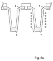
- FIGS. 5a to 5e show by means of a vertical section through several molds 4, 5 schematically the cyclically inductive heating of the molds 4, 5 by means of an inductor 3, wherein the molds 4, 5 are interspersed with at least one additive 6, 7 which can be inductively heated.
- the at least one additive 6, 7 may be the same additive.
- the casting molds 4, 5 are fastened on a structural element, wherein on the structural element, for example, at least one first casting mold 4 and at least one second casting mold 5 can be fastened. That is, the structural element may carry the molds 4, 5.
- the movement of the casting molds 4, 5 is thus accompanied by the movement of the structural element. It is known to the person skilled in the art that the structural element can also carry other casting molds (not shown).
- FIG. 5a schematically shows the beginning of a first time period in a first power stroke, wherein the first mold 4 and the inductor 3 are both in a first position, which may be referred to as the starting positions of the first mold 4 and the inductor 3.
- the first Casting mold 4 and the inductor 3 are then moved in a relative movement.
- the inductor 3 is moved from its first position to the first mold 4 in a second position.
- the first mold 4 remains in its first position.
- the movement of the inductor 3 is in the FIG. 5a represented by the vertical arrows.
- the second position of the inductor 3 is in FIG. 5b shown.
- the person skilled in the art is aware that the relative movement of the first mold 4 and of the inductor 3 described here can also be effected by the inductor 3 remaining in its first position and the first mold 4 being moved to the inductor 3.
- the first mold 4 can also be fastened to a structural element which performs the same relative movements as the first mold 4.
- the relative movement of the inductor 3 and the structural element can also be carried out, for example, by simultaneously moving the inductor 3 and the structural element.
- the first period of the first power stroke is completed upon reaching the second position of the inductor 3.
- FIG. 5b schematically shows a second time period in the first power stroke, wherein the inductor 3 is in the second position, in which the first mold 4 can be heated inductively by the inductor 3.
- the second period of the first power stroke is completed with the completion of the inductive heating.
- the end of the inductive heating by the inductor 3 may be indicated by, for example, a temperature sensor (not shown).
- the temperature sensor can output a signal to a controller of the inductor 3, and based on the signal, the inductive heating can be controlled.
- the first mold 4 and the inductor 3 are moved away from each other in a relative movement. In this case, the inductor 3 from its second position - as in FIG.
- FIG. 5c schematically shows the end of a third time period in the first power stroke, wherein the inductor 3 back to its first position - as in FIG. 5a shown - moved.
- the movement of the inductor 3 is in the FIG. 5c represented by the vertical arrows.
- the third period of the first power stroke is completed upon reaching the home position. With the completion of the third period of the first power stroke and the first power stroke is completed. Subsequently, the first mold 4 and the inductor 3 in a further relative movement, which can also be referred to as further clocking, are moved.
- the indexing will be in the FIG. 5d represented by the horizontal arrow.
- the first mold 4 is moved from its first position to a second position, wherein the first mold 4 moves away from the inductor 3 horizontally.
- the inductor 3 remains in its first position.
- the first mold 4 is mounted on a structural element on which at least a second mold 5 is fixed, and the at least one second mold 5 is moved when moved by the movement of the structural element, the first mold 4 becomes.
- the at least one second casting mold 5 is also indexed further.
- the indexing can be completed, for example, when the at least one second casting mold 5 reaches a first position that corresponds to the first position of the first casting mold 4. With the achievement of the first position of the at least one second mold 5, a second power stroke can begin.
- the skilled person is aware that the relative movement during the indexing can also be performed by the inductor 3 is moved while the structural element and thus the first mold 4 and the at least one second mold 5 are not moved.
- the relative movement of the inductor 3 and the structural element during the indexing can be carried out, for example, by simultaneously moving the inductor 3 and the structural element.
- FIG. 5d schematically the beginning of a first time period in the second power stroke.
- the second mold 5 and the inductor 3 are both in a first position.
- the second mold 5 and the inductor 3 are then moved in a relative movement.
- the inductor 3 is moved from its first position to the second mold 5 in a second position.
- the second mold 5 remains in its first position.
- the movement of the inductor 3 is in the FIG. 5d represented by the vertical arrows.
- the second position of the inductor 3 is in FIG. 5e shown.
- FIG. 5e schematically shows a second time period in the second power stroke, wherein the inductor 3 is in the second position, in which the second mold 5 can be heated inductively by the inductor 3.
- FIGS. 5a to 5e a method for cyclically inductive heating of casting molds is shown, with which a plurality of molds can be heated in cycles by inductive means, so that this method can be implemented as a clock-controlled process in lipstick lead manufacturing.
Landscapes
- Engineering & Computer Science (AREA)
- Mechanical Engineering (AREA)
- Manufacturing & Machinery (AREA)
- Health & Medical Sciences (AREA)
- Toxicology (AREA)
- Moulds For Moulding Plastics Or The Like (AREA)
- General Induction Heating (AREA)
Abstract
Ein Verfahren und ein System zum Erhitzen von Gießformen (1), insbesondere zum Erhitzen von Gießformen (1) für kosmetische Produkte, wird beschrieben. Das System weist zumindest einen Induktor (3) zum Erzeugen von zumindest einem magnetischen Wechselfeld und zumindest eine Gießform (1) auf, wobei die Gießform (1) im Wesentlichen aus einem Kunststoff oder einem Elastomer besteht und zumindest mit einem Zusatzstoff (2) durchsetzt ist, wobei der Zusatzstoff (2) induktiv erhitzt werden kann.A method and a system for heating molds (1), in particular for heating molds (1) for cosmetic products, is described. The system has at least one inductor (3) for generating at least one alternating magnetic field and at least one casting mold (1), wherein the casting mold (1) substantially consists of a plastic or an elastomer and is at least interspersed with an additive (2) , wherein the additive (2) can be heated inductively.
Description
Die vorliegende Erfindung betrifft im Allgemeinen das induktive Erhitzen von Gießformen für kosmetische Produkte, insbesondere das induktive Erhitzen von Gießformen, die aus einem Elastomer oder aus einem Kunststoff bestehen.The present invention generally relates to the inductive heating of molds for cosmetic products, in particular the inductive heating of molds, which consist of an elastomer or of a plastic.
Gießformen dienen bei der Herstellung von kosmetischen Produkten beispielsweise zur Aufnahme eines erwärmten und fließfähigen Gemisches unterschiedlicher Wachse und Additive, wobei das Gemisch als pastöse Masse bezeichnet werden kann. Die pastöse Masse wird in die Gießformen gefüllt, um deren Gestalt anzunehmen. Eine Gießform kann dabei beispielsweise dazu verwendet werden, Lippenstiftminen zu formen. Die Gestalt der Lippenstiftmine entspricht dabei der inneren Kontur der Gießform, in die die pastöse Masse gefüllt wurde, und in der diese abgekühlt und erstarrt ist. Dabei kann das Abkühlen aktiv geschehen, also durch das Zutun einer Kühlung geschehen, oder passiv, also ohne das Zutun einer Kühlung. Um eine möglichst glatte Oberfläche der Lippenstiftmine zu erzielen, muss während des Abfüllprozesses ein vorzeitiges Abkühlen und Erstarren des Teils der pastösen Masse verhindert werden, der mit der inneren Kontur der Gießform direkt in Kontakt kommt. Hierfür werden die Gießformen vor dem Befüllen mit der pastösen Masse auf ein erhöhtes Temperaturniveau gebracht, d.h. die Gießformen werden aufgeheizt beziehungsweise vorgewärmt, wodurch das vorzeitige Erstarren zumindest des Teils der pastösen Masse verhindert wird, der mit der inneren Kontur der Gießform direkt in Kontakt kommt. Durch vorzeitiges Abkühlen und Erstarren der pastösen Masse kann es ansonsten zur Bildung von Rissen, Poren und Fehlstellen auf der Oberfläche des späteren Erzeugnisses, beispielsweise der Lippenstiftmine, kommen. Um diesen Qualitätseinbußen entgegenzuwirken, werden die Gießformen vor und / oder während des Gießprozesses aufgeheizt.Molds used in the manufacture of cosmetic products, for example, for receiving a heated and flowable mixture of different waxes and additives, wherein the mixture can be referred to as pasty mass. The pasty mass is filled into the molds to assume their shape. A mold can be used, for example, to form lipstick leads. The shape of the lipstick lead corresponds to the inner contour of the mold, in which the pasty mass was filled, and in which it is cooled and solidified. In this case, the cooling can be done actively, that is done by the action of cooling, or passively, without the intervention of a cooling. In order to achieve the smoothest possible surface of the lipstick lead, premature cooling and solidification of the part of the pasty mass must be prevented during the filling process, which comes into direct contact with the inner contour of the casting mold. For this purpose, the molds are brought to an elevated temperature level before filling with the pasty mass, ie the molds are heated or preheated, whereby the premature solidification of at least the part of the pasty mass is prevented, which comes into direct contact with the inner contour of the mold. By premature cooling and solidification of the pasty mass may otherwise lead to the formation of cracks, pores and defects on the surface of the subsequent product, such as the lipstick lead come. To counteract these quality losses, the molds are heated before and / or during the casting process.
Im Stand der Technik sind verschiedene Verfahren und Vorrichtungen bekannt, mit deren Hilfe Gießformen aufgeheizt werden können, um bei deren Befüllung mit einer pastösen Masse das vorzeitige Abkühlen und Erstarren der pastösen Masse zu verhindern.In the prior art, various methods and devices are known, with the aid of which molds can be heated to prevent their premature cooling and solidification of the pasty mass when they are filled with a pasty mass.
Beispielsweise beschreibt
Dies hat aber den Nachteil, dass ein Wärmeeintrag in die Formen nur indirekt geschieht, nämlich über den Wärmeträger Wasser. Gerade bei Gießformen, die aus schlecht wärmeleitenden Stoffen wie Kunststoffen oder Elastomeren bestehen, führt dies zu langen Verzögerungen im Prozesszyklus. Des Weiteren kann ein gleichmäßiger Wärmeeintrag nicht gewährleistet werden. Außerdem kann es bei derartigen Systemen meist zum direkten Kontakt zwischen dem Wärmeträgermedium und den Gießformen kommen. Dies kann dazu führen, dass die Gießformen frühzeitig abgenutzt werden oder sich an den Gießformen anderweitige Ablagerungen bilden, die sich nachteilig auf die Herstellung der kosmetischen Produkte auswirken können.However, this has the disadvantage that a heat input into the forms only happens indirectly, namely via the heat transfer medium water. Especially with molds that consist of poorly heat-conductive materials such as plastics or elastomers, this leads to long delays in the process cycle. Furthermore, a uniform heat input can not be guaranteed. In addition, in such systems usually come to direct contact between the heat transfer medium and the molds. This can lead to the casting molds being worn out prematurely or forming other deposits on the casting molds, which can adversely affect the production of the cosmetic products.
Aufgabe der vorliegenden Erfindung ist es daher, ein Verfahren, eine Gießform und ein System bereitzustellen, die die oben genannten Nachteile nicht aufweisen. Insbesondere soll mit dem Verfahren und dem System ein gezieltes Vorwärmen der Gießformen möglich sein, auch wenn diese aus einem schlecht wärmeleitenden Material bestehen.The object of the present invention is therefore to provide a method, a casting mold and a system which do not have the abovementioned disadvantages. In particular, should be possible with the method and the system, a targeted preheating of the molds, even if they consist of a poor thermal conductivity material.
Diese Aufgabe wird mit dem Verfahren, der Gießform und dem System der unabhängigen Ansprüche gelöst. Vorteilhafte Ausführungsformen sind in den Unteransprüchen beschrieben.This object is achieved with the method, the mold and the system of the independent claims. Advantageous embodiments are described in the subclaims.
Das erfindungsgemäße Verfahren zum induktiven Erhitzen von Gießformen, insbesondere zum induktiven Erhitzen von Gießformen für kosmetische Produkte, weist auf das Erzeugen von zumindest einem magnetischen Wechselfeld mit Hilfe von zumindest einem Induktor und das induktive Erhitzen von zumindest einer Gießform, wobei die zumindest eine Gießform im Wesentlichen aus einem Kunststoff oder Elastomer besteht und mit zumindest einem Zusatzstoff durchsetzt ist, wobei der zumindest eine Zusatzstoff induktiv erhitzt werden kann. Dadurch, dass die Gießform im Wesentlichen aus einem Kunststoff oder Elastomer besteht, kann diese zumindest teilweise flexibel sein.The inventive method for inductive heating of molds, in particular for inductive heating of molds for cosmetic products, comprises generating at least one alternating magnetic field by means of at least one inductor and the inductive heating of at least one mold, wherein the at least one mold consists essentially of a plastic or elastomer and is interspersed with at least one additive, wherein the at least one additive can be heated inductively. Because the casting mold substantially consists of a plastic or elastomer, it can be at least partially flexible.
Das induktive Erhitzen beruht darauf, dass der zumindest eine Induktor von einem Wechselstrom durchströmt werden kann, der zumindest ein magnetisches Feld um den zumindest einen Induktor erzeugt. Das magnetische Feld wiederum induziert in dem Zusatzstoff, mit dem die Gießform durchsetzt ist, Wirbelströme, die direkt in Wärme umgewandelt werden, wobei die Wärme an das Material abgegeben wird, das den Zusatzstoff umgibt. Hierdurch wird auch dieses Material erhitzt beziehungsweise aufgewärmt. Der Zusatzstoff in der Gießform wird somit induktiv erhitzt und bewirkt einen Wärmeeintrag in das Material der Gießform, das den Zusatzstoff umgibt. Es kann also davon gesprochen werden, dass der Zusatzstoff direkt erhitzt wird, wohingegen das Material der Gießform indirekt erhitzt wird. Die Temperatur, auf die die Gießform erhitzt wird, hängt dabei unter anderem von der Stärke der erzeugten Wirbelströme ab. Die Stärke der Wirbelströme ist dabei abhängig von dem Abstand zwischen dem Induktor und der dem Induktor zugewandten Oberfläche der Gießform sowie von der Stärke des Wechselstromes, der den zumindest einen Induktor durchfließt. Die Temperatur kann dabei beispielsweise über die zuvor genannten Faktoren so geregelt werden, dass es zu keinen Schädigungen des Materials aufgrund von Überhitzung kommt, ein gezielter Wärmeeintrag in die Gießform aber ermöglicht wird.The inductive heating is based on the fact that the at least one inductor can be traversed by an alternating current which generates at least one magnetic field around the at least one inductor. The magnetic field, in turn, induces eddy currents in the additive with which the mold is interspersed, which are converted directly into heat, the heat being given off to the material surrounding the additive. As a result, this material is heated or warmed up. The additive in the mold is thus heated inductively and causes a heat input into the material of the mold, which surrounds the additive. It can therefore be said that the additive is heated directly, whereas the material of the mold is heated indirectly. The temperature to which the mold is heated, depends inter alia on the strength of the eddy currents generated. The strength of the eddy currents is dependent on the distance between the inductor and the surface of the casting mold facing the inductor and on the strength of the alternating current flowing through the at least one inductor. The temperature can be regulated, for example, via the factors mentioned above so that there is no damage to the material due to overheating, a targeted heat input into the mold but is possible.
Das erfindungsgemäße Verfahren stellt erstmalig ein Verfahren bereit, mit dem ein gezieltes Erhitzen von Gießformen für kosmetische Produkte möglich ist, d.h. ein Verfahren, bei dem das Erhitzen der Gießform möglichst schnell und gezielt stattfindet und eine möglichst kurze Zykluszeit bei der Herstellung von kosmetischen Produkten erreicht werden kann. Des Weiteren kann ein derartiges Verfahren auch nahezu kontaktlos ausgeführt werden.The method according to the invention provides for the first time a method by which targeted heating of casting molds for cosmetic products is possible, ie a method in which the heating of the casting mold takes place as quickly and selectively as possible and a cycle time as short as possible is achieved in the production of cosmetic products can. Furthermore, such a method can also be carried out almost contactless.
In einer bevorzugten Ausführungsform des erfindungsgemäßen Verfahrens wird das zumindest eine magnetische Feld, erzeugt durch den zumindest einen Induktor, geregelt. Das magnetische Feld setzt sich aus magnetischen Feldlinien zusammen, die auf geschlossenen Bahnen um den Induktor herum verlaufen. Das magnetische Feld kann dabei über die beiden physikalischen Größen magnetische Feldstärke und magnetische Flussdichte quantifiziert werden. Die Regelung des magnetischen Feldes kann demnach beispielsweise über die Regelung der magnetischen Feldstärke und der magnetischen Flussdichte stattfinden. Die magnetische Feldstärke und die magnetische Flussdichte können dabei durch die Geometrie des Induktors selbst gesteuert werden, aber auch durch den Wechselstrom geregelt werden, der den Induktor durchströmt. Das Regeln des zumindest einen magnetischen Feldes kann dabei das Regeln der Stärke des Wechselstromes beinhalten. Die Stärke des den Induktor durchströmenden Wechselstromes ist dabei proportional zu der Stärke der erzeugten magnetischen Feldstärke und der magnetischen Flussdichte. Die magnetische Flussdichte entspricht der magnetischen Feldstärke multipliziert mit der magnetischen Feldkonstante und der Permeabilitätszahl. Die periodische Änderung des Stromes bewirkt eine periodische Änderung des vom Induktor erzeugten magnetischen Feldes. Aufgrund der periodischen Änderung des magnetischen Feldes kann das magnetische Feld auch als magnetisches Wechselfeld bezeichnet werden. Mit der Regelung der Stärke des Wechselstromes kann Einfluss auf die Stärke der induzierten Wirbelströme genommen werden, wodurch der Grad des Wärmeeintrages geregelt werden kann. Das Erhitzen der Gießform kann also geregelt werden. Dabei gilt, je stärker der den Induktor durchströmende Wechselstrom ist, desto stärker sind die erzeugten Wirbelströme und desto größer ist der stattfindende Wärmeeintrag. Beispielsweise kann die Stärke des Wechselstroms im Bereich zwischen 50 A und 400 A liegen.In a preferred embodiment of the method according to the invention, the at least one magnetic field generated by the at least one inductor is regulated. The magnetic field is composed of magnetic field lines that run on closed paths around the inductor. The magnetic field can be quantified by the two physical parameters magnetic field strength and magnetic flux density. The regulation of the magnetic field can therefore take place, for example, via the regulation of the magnetic field strength and the magnetic flux density. The magnetic field strength and the magnetic flux density can be controlled by the geometry of the inductor itself, but also be controlled by the alternating current flowing through the inductor. The regulation of the at least one magnetic field may include regulating the strength of the alternating current. The strength of the alternating current flowing through the inductor is proportional to the strength of the generated magnetic field strength and the magnetic flux density. The magnetic flux density corresponds to the magnetic field strength multiplied by the magnetic field constant and the permeability number. The periodic change of the current causes a periodic change of the magnetic field generated by the inductor. Due to the periodic change of the magnetic field, the magnetic field can also be called an alternating magnetic field. By controlling the strength of the alternating current, it is possible to influence the strength of the induced eddy currents, whereby the degree of heat input can be regulated. The heating of the mold can therefore be regulated. In this case, the stronger the alternating current flowing through the inductor, the stronger the generated eddy currents and the greater the heat input occurring. For example, the strength of the alternating current can be in the range between 50 A and 400 A.
Zusätzlich oder alternativ zur Regelung der Stärke des Wechselstromes, der den zumindest einen Induktor durchströmt, kann auch die Frequenz des Wechselstromes geregelt werden. Die Frequenz des Wechselstromes, von dem der erfindungsgemäß zumindest eine Induktor durchflossen wird, gibt die Frequenz vor, mit der das magnetische Wechselfeld seine Richtung wechselt.Additionally or alternatively, to regulate the strength of the alternating current, which flows through the at least one inductor, and the frequency of the alternating current can be controlled. The frequency of the alternating current, through which at least one inductor flows according to the invention, determines the frequency with which the alternating magnetic field changes its direction.
Im Allgemeinen hat die Frequenz eines magnetischen Wechselfeldes bei dem induktiven Erhitzen einen Einfluss auf die Verteilung der Stromdichte von den Wirbelströmen, die in dem zu erhitzenden Zusatzstoff der Gießform durch das magnetische Wechselfeld induziert werden. Dabei kann beispielsweise die größte Stromdichte von den induzierten Wirbelströmen in der zumindest einen Gießform auch an ihrer dem Induktor zugewandten Oberfläche auftreten und kann mit zunehmendem Abstand abnehmen. Die Eindringtiefe der induzierten Wirbelströme hängt dabei von der Frequenz des Wechselstromes ab, von dem der Induktor durchflossen wird. Je höher die Frequenz ist, desto geringer ist die Eindringtiefe der induzierten Wirbelströme. Über die Frequenz des Wechselstromes, der den Induktor durchströmt, lässt sich somit die Eindringtiefe der induzierten Wirbelströme bestimmen. Umgibt der Induktor beispielsweise zumindest teilweise die Gießform, so kann beispielsweise die Frequenz so geregelt werden, dass die Eindringtiefe der induzierten Wirbelströme derart eingestellt ist, dass die Wirbelströme zunächst einen Bereich der Gießform erhitzen, der dem Induktor zugewandt ist, und die Frequenz kann anschließend derart geregelt werden, dass die Eindringtiefe der induzierten Wirbelströme derart eingestellt ist, dass ein weiter vom Induktor beabstandeter Bereich der Gießform erhitzt wird. Beispielsweise kann die Frequenz des Wechselstroms im Bereich zwischen 50 Hz und 450 kHz liegen.In general, the frequency of an alternating magnetic field in the inductive heating has an influence on the distribution of the current density of the eddy currents, which are induced in the heated additive of the mold by the alternating magnetic field. In this case, for example, the largest current density of the induced eddy currents in the at least one casting mold also occur on its surface facing the inductor and can decrease with increasing distance. The penetration depth of the induced eddy currents depends on the frequency of the alternating current from which the inductor flows. The higher the frequency, the lower the penetration depth of the induced eddy currents. The frequency of the alternating current flowing through the inductor can thus be used to determine the penetration depth of the induced eddy currents. If, for example, the inductor at least partially surrounds the casting mold, then the frequency can be regulated such that the penetration depth of the induced eddy currents is set such that the eddy currents first heat a region of the casting mold facing the inductor, and the frequency can then be such be regulated that the penetration depth of the induced eddy currents is set so that a further spaced from the inductor portion of the mold is heated. For example, the frequency of the alternating current may be in the range between 50 Hz and 450 kHz.
Über die Regelung der Stärke des Wechselstromes und dessen Frequenz lässt sich somit der Wärmeeintrag in die Gießform regeln und es lässt sich ein gezieltes Wärmeprofil erzeugen. Dabei kann das erzeugte Wärmeprofil an die Eigenschaften der pastösen Masse angepasst werden, die in die Gießform gefüllt wird. Das Wärmeprofil kann also auf die Wachse und Additive abgestimmt sein, aus denen die pastöse Masse besteht, und kann derart angepasst sein, dass die pastöse Masse gezielt in der Gießform Erstarren kann. Dabei kann es beispielsweise auch vorteilhaft sein, wenn der Induktor auch während des Befüllens und / oder nach dem Befüllen der Gießform Wirbelströme erzeugt, deren Stärke und Eindringtiefe aber mit fortscheitender Zeit abnimmt, so dass die pastöse Masse gezielt in der Gießform abkühlen und damit erstarren kann.By controlling the strength of the alternating current and its frequency can thus regulate the heat input into the mold and it can produce a targeted heat profile. In this case, the generated heat profile can be adapted to the properties of the pasty mass, which is filled in the mold. The heat profile can thus be matched to the waxes and additives that make up the pasty mass, and can be adapted so that the pasty mass can solidify targeted in the mold. It may also be advantageous, for example, if the inductor also generates eddy currents during filling and / or after filling the casting mold, but whose thickness and penetration depth decreases as time passes, so that the pasty mass can specifically cool in the casting mold and solidify therewith ,
In einer weiteren bevorzugten Ausführungsform des erfindungsgemäßen Verfahrens weist das Verfahren auf das Einstellen eines Abstandes zwischen dem zumindest einen Induktor und der zumindest einen Gießform. Über den Abstand zwischen dem Induktor und der Gießform lässt sich die Flächendichte der magnetischen Feldlinien des vom Induktor erzeugten magnetischen Wechselfeldes regeln, mit der das magnetische Wechselfeld die Gießform durchdringt. Mit dem Abstand lässt sich also auch der Wärmeeintrag regeln. Der Grad des Wärmeeintrages beziehungsweise der induzierten Wirbelströme verhält sich dabei proportional zur Flächendichte der magnetischen Feldlinien, von denen die Gießform durchdrungen werden, und wirkt sich somit proportional auf den Grad des Erhitzens der Gießform aus. Mit dem Einstellen des Abstandes zwischen dem Induktor und der Gießform kann somit der Grad des Erhitzens der zumindest einen Gießform gesteuert werden. Man kann auch sagen, dass mit dem Einstellen des Abstandes zwischen dem Induktor und der Gießform der Wirkungsgrad des induktiven Erhitzens geregelt werden kann. Der Abstand zwischen dem Induktor und der Gießform kann dabei durch eine Bewegung des Induktors und / oder der Gießform eingestellt werden.In a further preferred embodiment of the method according to the invention, the method comprises setting a distance between the at least one inductor and the at least one casting mold. The areal density of the magnetic field lines of the alternating magnetic field generated by the inductor, with which the alternating magnetic field penetrates the casting mold, can be regulated via the distance between the inductor and the casting mold. With the distance can thus also regulate the heat input. The degree of heat input or the induced eddy currents is proportional to the surface density of the magnetic field lines, which are penetrated by the mold, and thus has a proportional effect on the degree of heating of the mold. Thus, by adjusting the distance between the inductor and the mold, the degree of heating of the at least one mold can be controlled. It can also be said that by adjusting the distance between the inductor and the mold, the inductive heating efficiency can be controlled. The distance between the inductor and the mold can be adjusted by a movement of the inductor and / or the mold.
In einer weiteren bevorzugten Ausführungsform des erfindungsgemäßen Verfahrens weist das Verfahren auf das Bestimmen einer Temperatur von der zumindest einen zu erhitzenden Gießform und das Steuern des induktiven Erhitzens der zumindest einen Gießform, basierend auf der bestimmten Temperatur. Mit dem induktiven Erhitzen der zumindest einen Gießform wird die Gießform vor dem Befüllen mit der pastösen Masse erfindungsgemäß auf ein erhöhtes Temperaturniveau gebracht. Das erhöhte Temperaturniveau der Gießform wird dabei so gewählt, dass die pastöse Masse während des gesamten Befüllvorgangs einen fließfähigen Zustand beibehält. Insbesondere soll durch das erhöhte Temperaturniveau der Gießform die pastöse Masse an ihren Rändern, also dort, wo sie direkten Kontakt mit der Wandung der Gießform hat, während des gesamten Befüllvorgangs einen fließfähigen Zustand beibehalten. Die Temperatur der zumindest einen Gießform kann beispielsweise vor dem Beginn des induktiven Erhitzens bestimmt werden und stellt einen Istwert der Temperatur der Gießform vor dem Beginn des Befüllvorgangs dar. Der Istwert kann mit einem Sollwert der Temperatur der zumindest einen Gießform verglichen werden, der beispielsweise die Solltemperatur, also das erhöhte Temperaturniveau der Gießform vor dem Beginn des Befüllvorgangs, darstellt. Aus der Differenz zwischen dem Istwert und dem Sollwert der Temperatur der zumindest einen Gießform kann der Grad der Erwärmung ermittelt werden, der notwendig ist, um die Gießform auf die gewünschte Solltemperatur induktiv zu erhitzen. Die Temperatur kann während des induktiven Erhitzens der Gießform in regelmäßigen Abständen ermittelt werden. Der Sollwert der Temperatur der zumindest einen Gießform kann einen oberen Grenzwert darstellen und das induktive Erhitzen der zumindest einen Gießform kann dabei so gesteuert werden, dass das induktive Erhitzen der zumindest einen Gießform beendet wird, sobald die Temperatur der Gießform den oberen Grenzwert überschreitet. Die Solltemperatur der Gießform kann beispielsweise auch vor dem Beginn des Befüllvorgangs auf einen Bereich eingestellt werden, der als oberer Temperaturbereich bezeichnet werden kann, und der von einem oberen und von einem unteren Grenzwert begrenzt wird. Das induktive Erhitzen der zumindest einen Gießform kann dabei so gesteuert werden, dass das induktive Erhitzen der zumindest einen Gießform unterbrochen wird, sobald die Temperatur der Gießform den oberen Grenzwert überschreitet, und dass das induktive Erhitzen der zumindest einen Gießform fortgesetzt wird, sobald die Temperatur der Gießform den unteren Grenzwert unterschreitet. Der Wechsel zwischen Unterbrechen und Fortsetzen des induktiven Erhitzens kann solange wiederholt werden, wie gewünscht und / oder solange, wie es sinnvoll erscheint. Beispielsweise kann der Wechsel zwischen Unterbrechen und Fortsetzen des induktiven Erhitzens noch während des Befüllvorgangs stattfinden. Dem Fachmann ist bewusst, dass der Wechsel zwischen Unterbrechen und Fortsetzen des induktiven Erhitzens als ein Regelkreis bezeichnet werden kann. Dieser Regelkreis kann als ein Schwingkreis dargestellt werden und der Fachmann ist in der Lage die Parameter der verschiedenen Komponenten in dem Schwingkreis so einzustellen, dass eine stabile Regelung der Temperatur der zumindest einen Gießform ermöglicht wird. Die Temperatur der zumindest einen Gießform kann dabei so geregelt werden, dass unterschiedliche Bereiche der Gießform unterschiedlich stark erhitzt werden. Beispielsweise kann die Temperatur während des Befüllvorgangs in einem unteren Bereich der Gießform, der bereits mit der pastösen Masse gefüllt ist, reduziert werden, während in einem oberen Bereich der Gießform, in dem die Gießform gerade mit der pastösen Masse befüllt wird, ein höheres Temperaturniveau aufrechterhalten wird. Erfindungsgemäß kann die Temperatur auf der innenliegenden Oberfläche, also der inneren Kontur, der zumindest einen Gießform bestimmt werden aber es kann auch die Temperatur auf der außenliegenden Oberfläche, also der äußeren Kontur, der zumindest einen Gießform bestimmt werden. Beispielsweise kann die Temperatur im Inneren der zumindest einen Gießform bestimmt werden, um bei einer Bestimmung der Temperatur der zumindest einen Gießform während des Befüllvorgangs den Befüllvorgang der zumindest einen Gießform nur in einem möglichst geringen Maß zu stören. Der Grad der Erwärmung kann über die Regelung der oben beschriebenen Parameter so beeinflusst werden, dass ein möglichst schnelles und gezieltes Erhitzen der zumindest einen Gießform stattfindet, ohne dass das Material durch Überhitzung beschädigt wird, wobei es sich bei dem Material um das Material handeln kann, aus dem die zumindest eine Gießform im Wesentlichen besteht aber auch um das Material der Wachse und Additive, aus denen die pastöse Masse besteht. Dem Fachmann sind noch weitere Parameter bekannt, über die der Grad der Erwärmung beeinflusst werden kann, beispielsweise über die Wahl des Materials, aus dem der Induktor besteht.In a further preferred embodiment of the method according to the invention, the method comprises determining a temperature of the at least one mold to be heated and controlling the inductive heating of the at least one mold based on the determined temperature. With the inductive heating of the at least one casting mold, the casting mold is brought to an elevated temperature level according to the invention prior to filling with the pasty composition. The elevated temperature level of the mold is chosen so that the pasty mass maintains a flowable state during the entire filling process. In particular, due to the elevated temperature level of the casting mold, the paste-like mass should retain a flowable state at its edges, ie where it has direct contact with the wall of the casting mold, during the entire filling process. The temperature of the at least one mold can be determined, for example, before the start of the inductive heating, and represents an actual value of the temperature of the mold before the start of the filling process. The actual value can be compared with a target value of the temperature of the at least one mold, for example, the target temperature, ie the elevated temperature level of the mold before the start of the filling process, represents. From the difference between the actual value and the desired value of the temperature of the at least one casting mold, the degree of heating that is necessary to inductively heat the casting mold to the desired setpoint temperature can be determined. The temperature may be determined at regular intervals during inductive heating of the mold. The desired value of the temperature of the at least one mold can represent an upper limit and the inductive heating of the at least one mold can be controlled so that the inductive heating of the at least one mold is terminated as soon as the temperature of the mold exceeds the upper limit. The setpoint temperature of the casting mold can, for example, also be set to a range which can be referred to as the upper temperature range before the start of the filling operation and which is limited by an upper and a lower limit value. The inductive heating of the at least one mold can be controlled so that the inductive heating of the at least one mold is interrupted when the temperature of the mold exceeds the upper limit, and that the inductive heating of the at least one mold is continued as soon as the temperature of Mold falls below the lower limit. The change between interrupting and resuming the inductive heating can be repeated as long as desired and / or as long as it makes sense. For example, the change between interrupting and resuming the inductive heating still take place during the filling process. It will be appreciated by those skilled in the art that switching between interrupting and continuing inductive heating may be referred to as a closed loop. This control loop can be represented as a resonant circuit and the person skilled in the art is able to adjust the parameters of the various components in the oscillatory circuit in such a way that a stable regulation of the temperature of the at least one casting mold is made possible. The temperature of the at least one casting mold can be regulated so that different regions of the casting mold be heated to different degrees. For example, during the filling process, the temperature in a lower region of the casting mold, which is already filled with the pasty mass, can be reduced, while in an upper region of the casting mold, in which the casting mold is being filled with the pasty mass, a higher temperature level is maintained becomes. According to the invention, the temperature on the inner surface, ie the inner contour, of the at least one casting mold can be determined, but it is also possible to determine the temperature on the outer surface, ie the outer contour, of the at least one casting mold. For example, the temperature in the interior of the at least one casting mold can be determined in order to disturb the filling process of the at least one casting mold only to the smallest possible extent when determining the temperature of the at least one casting mold during the filling process. The degree of heating can be influenced via the regulation of the parameters described above so that the at least one casting mold is heated as quickly and selectively as possible, without the material being damaged by overheating, wherein the material may be the material, from which the at least one mold essentially consists but also the material of the waxes and additives that make up the pasty mass. The skilled person is aware of other parameters by which the degree of heating can be influenced, for example via the choice of the material of which the inductor consists.
Die oben genannte Aufgabe wird auch gelöst durch eine erfindungsgemäße Gießform, insbesondere eine Gießform zum Formen von kosmetischen Produkten, die im Wesentlichen aus einem Kunststoff oder Elastomer besteht und die zumindest mit einem Zusatzstoff durchsetzt ist, wobei der Zusatzstoff induktiv erhitzt werden kann. Dadurch, dass die Gießform im Wesentlichen aus einem Kunststoff oder Elastomer besteht, kann diese zumindest teilweise flexibel sein. Der zumindest eine Zusatzstoff kann beispielsweise in Form von Partikeln dem Material, aus dem die Gießform geformt ist, beigegeben werden. Dabei können der Kunststoff oder das Elastomer der Gießform und der Zusatzstoff ein heterogenes Stoffgemisch bilden. Man kann sagen, dass es sich bei dem heterogenen Stoffgemisch um eine Dispersion handelt, wobei der Zusatzstoff in der Gießform eine disperse Phase und der Kunststoff oder das Elastomer in der Gießform ein Dispersionsmedium bilden. Das Dispersionsmedium verleiht der Gießform beispielsweise Flexibilität und eine glatte Oberfläche und die disperse Phase reagiert beispielsweise auf das induzierte magnetische Wechselfeld und verleiht der Gießform die Eigenschaft, induktiv erhitzt werden zu können. Aufgrund der Wärmeübertragung wird bei dem induktiven Erhitzen der Gießform die erzeugte Wärme von der dispersen Phase auf das Dispersionsmedium übertragen und somit wird die Gießform erhitzt. Es kann auch gesagt werden, dass die disperse Phase direkt erhitzt wird, wohingegen das Dispersionsmedium indirekt erhitzt wird. Der Anteil der dispersen Phase in der Dispersion kann hierbei variieren und beispielsweise von den spezifischen Wärmekapazitäten und von den Wärmeleitfähigkeiten der verwendeten Materialien abhängen. Die disperse Phase weist in der Regel eine niedrigere spezifische Wärmkapazität und einen höheren Wärmeleitkoeffizienten auf, als das Dispersionsmedium, d.h. die disperse Phase lässt sich schnell auf ein hohes Temperaturniveau erhitzen, kann die erzeugte Wärme jedoch nicht lange speichern. Soll die induktiv erhitzte Gießform ihr einmal erreichtes hohes Temperaturniveau nach einer Unterbrechung des induktiven Erhitzens über einen langen Zeitraum halten können, ist ein niedriger Anteil der dispersen Phase in der Dispersion, also im Gefüge der Gießform, von Vorteil. Der Anteil der dispersen Phase kann also so niedrig sein, dass man sagen kann, dass die Gießform im Wesentlichen aus dem Dispersionsmedium, d.h. dem Kunststoff oder dem Elastomer besteht. Beispielsweise kann die Dispersion derart ausgestaltet sein, dass die disperse Phase in der Dispersion einen Masseanteil von bis zu 10% aufweist.The abovementioned object is also achieved by a casting mold according to the invention, in particular a casting mold for molding cosmetic products, which consists essentially of a plastic or elastomer and which is interspersed with at least one additive, wherein the additive can be heated inductively. Because the casting mold substantially consists of a plastic or elastomer, it can be at least partially flexible. The at least one additive can be added, for example in the form of particles, to the material from which the casting mold is formed. In this case, the plastic or the elastomer of the mold and the additive can form a heterogeneous mixture. You can say that it is wherein the heterogeneous composition is a dispersion, wherein the additive in the mold forms a disperse phase and the plastic or elastomer in the mold forms a dispersion medium. For example, the dispersion medium imparts flexibility and a smooth surface to the mold, and the dispersed phase, for example, responds to the induced alternating magnetic field and gives the mold the ability to be inductively heated. Due to the heat transfer, in the inductive heating of the mold, the generated heat is transferred from the dispersed phase to the dispersion medium, and thus the mold is heated. It can also be said that the disperse phase is heated directly, whereas the dispersion medium is indirectly heated. The proportion of the disperse phase in the dispersion may in this case vary and depend, for example, on the specific heat capacities and the thermal conductivities of the materials used. The disperse phase typically has a lower specific heat capacity and a higher coefficient of thermal conductivity than the dispersion medium, ie the disperse phase heats up quickly to a high temperature level but can not store the generated heat for a long time. If the induction-heated casting mold is to be able to maintain its high temperature level once it has been reached after interruption of the inductive heating over a long period of time, a lower proportion of the disperse phase in the dispersion, ie in the structure of the casting mold, is advantageous. The proportion of the disperse phase can therefore be so low that it can be said that the casting mold consists essentially of the dispersion medium, ie the plastic or the elastomer. For example, the dispersion can be designed such that the disperse phase in the dispersion has a mass fraction of up to 10%.
Soll andererseits beispielsweise ein schnelles Erhitzen der Gießform auf ein hohes Temperaturniveau ermöglicht werden, wobei nach einer Unterbrechung des induktiven Erhitzens die Gießform schnell wieder abkühlt, ist ein hoher Anteil der dispersen Phase von Vorteil. Der Anteil der dispersen Phase kann also so hoch sein, dass man gegebenenfalls auch sagen kann, dass die Gießform zum Teil aus dem Dispersionsmedium, d.h. einem Kunststoff oder Elastomer, besteht und zum anderen Teil aus der dispersen Phase.On the other hand, for example, a rapid heating of the mold to a high temperature level are made possible, wherein after an interruption of the inductive heating, the mold quickly cools again, a high proportion of the disperse phase is advantageous. The proportion of the disperse phase can therefore be so high that one can optionally say that the Mold partly from the dispersion medium, ie a plastic or elastomer, and the other part of the disperse phase.
Wie oben beschrieben, besteht die disperse Phase zumeist aus Partikeln, die induktiv erhitzbar sind, also erhitzt werden können. Die Partikel können hierbei in der Gießform beispielsweise gleichmäßig verteilt sein. Aus der gleichmäßigen Verteilung der Partikel kann eine gleichmäßige Wärmeleitfähigkeit und eine gleichmäßige spezifische Wärmekapazität der Gießform angenommen werden und der Grad des induktiven Erhitzens der Gießform kann über die bereits beschriebenen Parameter geregelt werden. Die Partikel können aber auch ungleichmäßig verteilt sein, woraus beispielsweise eine Häufung der Partikel in bestimmten Bereichen resultieren kann. Durch die Häufung der Partikel in bestimmten Bereichen in der Gießform, können die hohe Wärmeleitfähigkeit und die niedrige spezifische Wärmekapazität der Partikel beispielsweise so genutzt werden, dass eine Lenkung des Wärmestroms durch die Gießform hindurch oder auch an ihrer Oberfläche entlang stattfinden kann. Beispielsweise kann durch die Häufung der Partikel in einem bestimmten Bereich der Gießform ein hoher Grad des induktiven Erhitzens der Gießform in dem bestimmten Bereich konzentriert werden, wohingegen in einem anderen Bereich der Gießform ein niedriger Grad des induktiven Erhitzens der Gießform stattfinden kann. Bei dem induktiven Erhitzen der Gießform gilt es insbesondere diejenige Oberfläche der Gießform zu erhitzen, die mit der pastösen Masse in Kontakt kommt, also die innere Kontur der Gießform. Für ein möglichst effektives induktives Erhitzen der innenliegenden Kontur der Gießform, die die innenliegende Oberfläche der Gießform darstellt, können die Partikel beispielsweise in dem Bereich der innenliegenden Oberfläche der Gießform konzentriert werden, um diesen Bereich der Gießform gezielt zu erhitzen. Mit dem Bereich der innenliegenden Oberfläche der Gießform kann dabei beispielsweise ein Bereich gemeint sein, der von der innenliegenden Oberfläche der Gießform bis zur Hälfte der Dicke der Gießform in die Gießform hineinreicht. Die Partikel können eine bestimmte Größe aufweisen, die als Teilchengröße bezeichnet werden kann, wobei die Teilchengröße beispielsweise in Abhängigkeit von dem Verfahren gewählt werden kann, mit dem die Partikel in das Dispersionsmedium eingebracht werden. Die Teilchengröße kann beispielsweise auf die mechanischen Eigenschaften der Gießform angepasst werden. Zum Beispiel kann die Teilchengröße an die geforderte Flexibilität der Gießform angepasst werden. Die Teilchengröße kann beispielsweise auch auf die an die gewünschte Oberflächenbeschaffenheit der Gießform angepasst werden. Zum Beispiel kann die Teilchengröße angepasst werden, um eine glatte Oberfläche der Gießform bereitzustellen. Dem Fachmann sind weitere Kenngrößen bekannt, an welche die Teilchengröße der dispersen Phase in dem Dispersionsmedium angepasst werden kann. Die Partikel in der Gießform können beispielsweise eine Teilchengröße zwischen 40 µm und 400 µm aufweisen. Die Verteilung des zumindest einen Zusatzstoffes in Form von Partikeln in der Gießform geschieht bei der Herstellung der Gießform. Das Verfahren, mit dem die Partikel hierbei in die Gießform eingebracht werden, kann als Impfen bezeichnet werden. Hierbei werden die Partikel, die den zumindest einen Zusatzstoff bilden, und der Kunststoff bzw. das Elastomer miteinander vermischt. Dies ist möglich, da der zumindest eine Zusatzstoff beispielsweise keine chemische Verbindung mit dem Kunststoff bzw. dem Elastomer eingeht und nicht an der Vernetzung teilnimmt. Der Zusatzstoff und der Kunststoff bzw. das Elastomer müssen somit lediglich homogen vermischt werden.As described above, the disperse phase mostly consists of particles which can be heated inductively, ie can be heated. The particles may in this case be uniformly distributed in the casting mold, for example. From the uniform distribution of the particles, a uniform thermal conductivity and a uniform specific heat capacity of the mold can be assumed and the degree of inductive heating of the mold can be controlled by the parameters already described. However, the particles may also be distributed unevenly, which may result, for example, in an accumulation of the particles in certain areas. The accumulation of particles in certain areas in the mold, the high thermal conductivity and the low specific heat capacity of the particles can be used, for example, so that a steering of the heat flow through the mold or along its surface can take place. For example, by accumulating the particles in a particular area of the mold, a high degree of inductive heating of the mold can be concentrated in the particular area, whereas in another area of the mold, a low degree of inductive heating of the mold can take place. In the case of inductive heating of the casting mold, it is particularly important to heat that surface of the casting mold which comes into contact with the pasty mass, that is to say the inner contour of the casting mold. For most effective inductive heating of the inner contour of the mold, which represents the inner surface of the mold, the particles may be concentrated, for example, in the region of the inner surface of the mold to selectively heat this region of the mold. By way of example, the region of the inner surface of the casting mold may mean a region which extends from the inner surface of the casting mold into the casting mold up to half the thickness of the casting mold. The particles may have a certain size, which may be referred to as particle size, the particle size may be selected, for example, depending on the method by which the particles in the dispersion medium be introduced. The particle size can be adapted, for example, to the mechanical properties of the casting mold. For example, the particle size can be adapted to the required flexibility of the mold. For example, the particle size can also be adapted to the desired surface finish of the casting mold. For example, the particle size can be adjusted to provide a smooth surface of the mold. The person skilled in the art knows further parameters to which the particle size of the disperse phase in the dispersion medium can be adapted. The particles in the casting mold may have, for example, a particle size between 40 μm and 400 μm. The distribution of the at least one additive in the form of particles in the casting mold takes place during the production of the casting mold. The process by which the particles are introduced into the casting mold here can be referred to as seeding. Here, the particles which form the at least one additive, and the plastic or the elastomer are mixed together. This is possible because the at least one additive, for example, does not form a chemical bond with the plastic or the elastomer and does not participate in the crosslinking. The additive and the plastic or the elastomer must therefore be mixed only homogeneously.
In einer bevorzugten Ausführungsform der erfindungsgemäßen Gießform ist der Kunststoff ein Kunststoff aus der Gruppe von thermoplastisch verarbeitbaren Elastomeren (TPE) und das Elastomer ist ein Elastomer aus der Gruppe von thermisch vulkanisierbaren Silikonkautschuken, wie beispielsweise RTVs (room temperature vulcanized rubber) oder HTVs (high temperature vulcanized rubber). Das Elastomer kann auch ein Elastomer aus der Gruppe der LSRs (liquid silicone rubber) sein.In a preferred embodiment of the mold according to the invention, the plastic is a plastic from the group of thermoplastically processable elastomers (TPE) and the elastomer is an elastomer from the group of thermally vulcanizable silicone rubbers, such as RTVs (room temperature vulcanized rubber) or HTVs (high temperature vulcanized rubber). The elastomer may also be an elastomer from the group of LSRs (liquid silicone rubber).
In einer bevorzugten Ausführungsform der erfindungsgemäßen Gießform ist der zumindest eine Zusatzstoff ein Zusatzstoff aus der Gruppe von einem ferromagnetischen Stoff, wie zum Beispiel "MagSilica" von "Evonik". Des Weiteren ist dem Fachmann bewusst, dass auch andere Zusatzstoffe verwendet werden können, das ein entsprechendes induktives Erhitzen zur Folge haben. Beispielsweise können Metallpulver, die vorzugsweise einen Fe-Anteil > 50% aufweisen, wie sie beispielsweise aus der pulvermetallurgischen Spritzgießtechnik bekannt sind, verwendet werden. Die Zusatzstoffe können dabei beispielsweise Legierungsbestandteile von Kohlenstoff, Silizium, Chrom, Molybdän, Kobalt und Wolfram aufweisen.In a preferred embodiment of the casting mold according to the invention, the at least one additive is an additive from the group of a ferromagnetic substance, such as "MagSilica" from "Evonik". Furthermore, the person skilled in the art is aware that it is also possible to use other additives which result in a corresponding inductive heating. For example, metal powders, which preferably have an Fe content > 50%, as they are known, for example, from the powder metallurgical injection molding used. The additives may include, for example, alloying constituents of carbon, silicon, chromium, molybdenum, cobalt and tungsten.
Die oben genannte Aufgabe wird auch gelöst durch ein System zum Erhitzen von Gießformen, insbesondere zum Erhitzen von Gießformen für kosmetische Produkte. Das erfindungsgemäße System weist auf zumindest einen Induktor zum Erzeugen von zumindest einem magnetischen Wechselfeld und zumindest eine Gießform, wobei die Gießform im Wesentlichen aus einem Kunststoff oder Elastomer besteht und zumindest mit einem Zusatzstoff durchsetzt ist, wobei der Zusatzstoff induktiv erhitzt werden kann. Beispielsweise kann das System so aufgebaut sein, dass jeder Induktor und jede Gießform eine Komponente des Systems darstellen, und dass jeder Induktor ein magnetisches Wechselfeld erzeugt, das jeweils eine Gießform für das induktive Erhitzen durchdringt. Dem Fachmann ist bewusst, dass aber auch andere Anordnungen von den Komponenten in dem System möglich sind, um die Gießformen für das induktive Erhitzen einem magnetischen Wechselfeld auszusetzen. Beispielsweise können mehrere Gießformen von demselben magnetischen Wechselfeld durchdrungen werden.The above object is also achieved by a system for heating molds, in particular for heating molds for cosmetic products. The system according to the invention has at least one inductor for generating at least one alternating magnetic field and at least one casting mold, wherein the casting mold substantially consists of a plastic or elastomer and is at least interspersed with an additive, wherein the additive can be heated inductively. For example, the system may be constructed such that each inductor and each mold is a component of the system, and each inductor generates an alternating magnetic field, each penetrating a mold for inductive heating. It will be appreciated by those skilled in the art, however, that other arrangements of the components in the system are possible to expose the inductive heating molds to an alternating magnetic field. For example, several casting molds can be penetrated by the same alternating magnetic field.
In einer bevorzugten Ausführungsform weist das System auf ein Mittel zum Regeln der Stärke des Wechselstromes und / oder zum Regeln der Frequenz des Wechselstromes, von dem der zumindest eine Induktor zum Erzeugen des magnetischen Wechselfeldes durchflossen wird. Für die Regelung der Stärke des Wechselstromes und somit für die Leistungsregelung des Induktors, der von dem Wechselstrom durchflossen wird, können beispielsweise Wechselstromregler verwendet werden, die mit Thyristoren ausgestattet sind. Diese elektronischen Bauteile können in niedrigen, mittleren und hohen Leistungsbereichen eingesetzt werden. Für die Regelung der Frequenz des Wechselstromes können beispielsweise Frequenzumrichter verwendet werden, die eine in der Frequenz und in der Amplitude regelbare Wechselspannung generieren. Beispielsweise können Frequenzumrichter verwendet werden, die Eingänge für Sensorsignale aufweisen, und bei denen die generierte Wechselspannung in der Frequenz und der Amplitude abhängig ist von den eingehenden Sensorsignalen oder einer entsprechenden Steuerung. Der zumindest eine Induktor kann derart ausgestaltet sein, dass er in seinem Inneren zumindest einen Hohlraum aufweist, in den ein Kühlmedium eindringen kann. Beispielsweise kann das Kühlmedium durch den zumindest einen Hohlraum des zumindest einen Induktors befördert werden, indem es zwangsmäßig eingeführt wird, wie beispielsweise mit einer Pumpe. Bei dem Kühlmedium kann es sich beispielsweise um Wasser handeln. Dem Fachmann ist bewusst, dass für die Versorgung des zumindest einen Induktors Mittelfrequenz- und / oder Hochfrequenzgeneratoren eingesetzt werden können, welche die für das induktive Erhitzen notwendige elektrische Leistung über einen breiten Frequenzbereich liefern können. Die Stärke des Wechselstroms und die Frequenz des Wechselstroms können dabei so von einem Steueroszillator erfasst und angepasst werden, dass ein Wirkungsgradoptimum erreicht wird. Das bedeutet, dass ein möglichst großer Teil der aufgewandten elektrischen Energie in Wärmeenergie umgewandelt werden kann. Beispielsweise können hierfür Mittelfrequenz- und / oder Hochfrequenzgeneratoren, wie der TruHeat HF 3010 von Trumpf Hüttinger, eingesetzt werden.In a preferred embodiment, the system has a means for regulating the strength of the alternating current and / or for regulating the frequency of the alternating current, through which the at least one inductor for generating the alternating magnetic field is traversed. For the regulation of the strength of the alternating current and thus for the power control of the inductor, which is traversed by the alternating current, it is possible, for example, to use alternating current regulators equipped with thyristors. These electronic components can be used in low, medium and high power ranges. Frequency converters which generate an AC voltage which can be regulated in frequency and in amplitude, for example, can be used to regulate the frequency of the alternating current. For example, frequency inverters can be used which have inputs for sensor signals and where the generated AC voltage in the frequency and the amplitude depends on the incoming sensor signals or a corresponding control. The at least one inductor may be configured such that it has in its interior at least one cavity into which a cooling medium can penetrate. For example, the cooling medium may be conveyed through the at least one cavity of the at least one inductor by being forcibly introduced, such as with a pump. The cooling medium may be, for example, water. The person skilled in the art is aware that medium-frequency and / or high-frequency generators can be used for the supply of the at least one inductor, which can supply the electrical power necessary for the inductive heating over a wide frequency range. The strength of the alternating current and the frequency of the alternating current can be detected and adjusted by a control oscillator so that an optimum efficiency is achieved. This means that as much of the applied electrical energy as possible can be converted into heat energy. For example, medium-frequency and / or high-frequency generators, such as the TruHeat HF 3010 from Trumpf Hüttinger, can be used for this purpose.
In einer bevorzugten Ausführungsform des erfindungsgemäßen Systems wird die Stärke des Wechselstromes, von dem der zumindest eine Induktor durchflossen wird, im Bereich von 50 A bis 400 A eingestellt und die Frequenz des Wechselstromes, von dem der zumindest eine Induktor durchflossen wird, im Bereich von 50 Hz bis 450 kHz eingestellt.In a preferred embodiment of the system according to the invention, the intensity of the alternating current through which the at least one inductor flows is set in the range from 50 A to 400 A and the frequency of the alternating current through which at least one inductor flows is in the region of 50 Hz to 450 kHz.
In einer weiteren bevorzugten Ausführungsform weist das System auf ein Mittel zum Einstellen des Abstandes zwischen dem zumindest einen Induktor und der zumindest einen Gießform.In a further preferred embodiment, the system has a means for adjusting the distance between the at least one inductor and the at least one casting mold.
Der Abstand zwischen dem Induktor und der Gießform kann mittels optischer Messverfahren ermittelt werden. Insbesondere soll hierbei der Abstand zwischen dem Induktor und der dem Induktor zugewandten Oberfläche der Gießform ermittelt werden. Das optische Messverfahren erlaubt somit eine berührungslose Messung des Abstandes zwischen Induktor und der dem Induktor zugewandten Oberfläche, ohne störenden Eingriff in den Prozess des induktiven Erhitzens. Ein optisches Messverfahren kann beispielsweise mit dem Einsatz eines Lasers bereitgestellt werden, der nach dem Triangulationsprinzip arbeitet, mit dem der Abstand zwischen Induktor und der dem Induktor zugewandten Oberfläche der Gießform aus einer verhältnismäßig großen Entfernung ermittelt werden kann. Der Laser sendet hierbei Strahlen aus, die an der Oberfläche des Induktors und an der dem Induktor zugewandten Oberfläche der Gießform reflektiert werden und dann von einem optischen Sensor empfangen werden. Alternativ oder zusätzlich zum optischen Messverfahren kann der zumindest eine Induktor beispielsweise zumindest ein Strukturelement aufweisen, das an die Bewegung des zumindest einen Induktors gekoppelt ist, und die zumindest eine Gießform kann beispielsweise zumindest ein Strukturelement aufweisen, das an die Bewegung der zumindest einen Gießform gekoppelt ist, und der Abstand zwischen dem zumindest einen Induktor und der dem Induktor zugewandten Oberfläche der zumindest einen Gießform kann beispielsweise aus dem Abstand der Strukturelemente abgeleitet werden. In diesem Fall können beispielsweise einfache Kontaktsensoren verwendet werden, um den Abstand zwischen den Strukturelementen zu erfassen. Alternativ können hierfür auch induktive Sensoren oder kapazitive Sensoren verwendet werden. Dem Fachmann ist bewusst, dass aber auch andere Sensoren verwendet werden können, um den Abstand zwischen den Strukturelementen zu erfassen, die an die Bewegung des zumindest einen Induktors und an die Bewegung der zumindest einen Gießform gekoppelt sind.The distance between the inductor and the casting mold can be determined by means of optical measuring methods. In particular, in this case the distance between the inductor and the surface of the mold facing the inductor should be determined. The optical measuring method thus allows a Non-contact measurement of the distance between the inductor and the surface facing the inductor, without interfering with the process of inductive heating. An optical measuring method can be provided, for example, with the use of a laser, which works according to the triangulation principle, with which the distance between the inductor and the surface of the casting mold facing the inductor can be determined from a relatively large distance. In this case, the laser emits rays which are reflected on the surface of the inductor and on the surface of the casting mold facing the inductor and are then received by an optical sensor. As an alternative or in addition to the optical measuring method, the at least one inductor may have, for example, at least one structural element coupled to the movement of the at least one inductor, and the at least one casting mold may, for example, comprise at least one structural element coupled to the movement of the at least one casting mold and the distance between the at least one inductor and the surface of the at least one casting mold facing the inductor can be derived, for example, from the spacing of the structural elements. In this case, for example, simple contact sensors can be used to detect the distance between the structural elements. Alternatively, inductive sensors or capacitive sensors can be used for this purpose. Those skilled in the art will appreciate that other sensors may be used to detect the distance between the structural elements coupled to the movement of the at least one inductor and to the movement of the at least one mold.
Der Abstand zwischen dem zumindest einen Induktor und der dem Induktor zugewandten Oberfläche der zumindest einen Gießform kann über eine Relativbewegung des Induktors und der Gießform eingestellt werden. Dabei können der Induktor und die Gießform so angeordnet sein, dass die dem Induktor zugewandte Oberfläche der Gießform die Außenfläche der Gießform ist. In diesem Fall bewegen sich zum Einstellen des Abstandes zwischen dem Induktor und der dem Induktor zugewandten Oberfläche der Gießform der Induktor und die Gießform in der Art relativ zueinander, dass der Induktor die Gießform umschließt. Bei dem Induktor kann es sich hierbei beispielsweise um einen so genannten Innenfeldinduktor handeln, der wie eine Spule geformt ist, bei der die höchste magnetische Flussdichte des induzierten magnetischen Wechselfeldes im Inneren der Spule auftritt. Die Relativbewegung kann hierbei beispielsweise dadurch hervorgerufen werden, dass der Induktor mittels eines Hubmechanismus so an die Gießform herangeführt wird, dass er diese umschließt. Alternativ kann auch die Gießform mittels eines Hubmechanismus so bewegt werden, dass sie von dem Induktor umschlossen wird. Beispielsweise kann die Relativbewegung des Induktors und der Gießform durch eine gleichzeitige oder zeitlich versetzte Bewegung des Induktors und der Gießform erzeugt werden. Der Induktor und die dem Induktor zugewandte Oberfläche der Gießform können aber auch so angeordnet sein, dass die dem Induktor zugewandte Oberfläche der Gießform die Innenfläche der Gießform ist. In diesem Fall bewegen sich zum Einstellen des Abstandes zwischen dem Induktor und der dem Induktor zugewandten Oberfläche der Gießform in der Art relativ zueinander, dass der Induktor in die Gießform eintaucht. Bei dem Induktor kann es sich hierbei beispielsweise um einen so genannten Außenfeldinduktor handeln, bei dem die höchste magnetische Flussdichte des induzierten magnetischen Wechselfeldes außerhalb des Induktors auftritt. Die Relativbewegung kann hierbei beispielsweise dadurch hervorgerufen werden, dass der Induktor mittels eines Hubmechanismus so an die Gießform herangeführt wird, dass er in diese eintaucht. Alternativ kann auch die Gießform mittels eines Hubmechanismus so bewegt werden, dass sie den Induktor umschließt. Beispielsweise kann die Relativbewegung des Induktors und der Gießform auch durch eine gleichzeitige oder zeitlich versetzte Bewegung des Induktors und der Gießform erzeugt werden. Beispielsweise kann der zumindest eine Induktor und / oder die zumindest eine Gießform auch auf jeweils zumindest einem Strukturelement montiert sein und das Strukturelement kann von einem Hubmechanismus in Bewegung versetzt werden. Die Bewegung der Strukturelemente kann dabei derart angepasst sein, dass sie einer Taktung folgt, wobei die Taktung eine Aufteilung von aufeinander folgenden Arbeitstakten in Zeitabschnitte darstellt.The distance between the at least one inductor and the surface of the at least one casting mold facing the inductor can be adjusted via a relative movement of the inductor and the casting mold. In this case, the inductor and the casting mold can be arranged so that the surface of the casting mold facing the inductor is the outer surface of the casting mold. In this case, to adjust the distance between the inductor and the inductor-facing surface of the mold, the inductor and the mold move relative to each other such that the inductor moves the inductor Encloses casting mold. By way of example, the inductor may be a so-called internal field inductor which is shaped like a coil in which the highest magnetic flux density of the induced alternating magnetic field occurs inside the coil. The relative movement can in this case be caused, for example, by the fact that the inductor is brought to the casting mold by means of a lifting mechanism in such a way that it encloses it. Alternatively, the mold can be moved by means of a lifting mechanism so that it is enclosed by the inductor. For example, the relative movement of the inductor and the mold can be produced by a simultaneous or staggered movement of the inductor and the mold. However, the inductor and the surface of the casting mold facing the inductor can also be arranged so that the surface of the casting mold facing the inductor is the inner face of the casting mold. In this case, to adjust the distance between the inductor and the surface of the mold facing the inductor, in the manner relative to each other, the inductor is immersed in the mold. The inductor may be, for example, a so-called Außenfeldinduktor, in which the highest magnetic flux density of the induced alternating magnetic field occurs outside of the inductor. The relative movement can in this case be caused, for example, that the inductor is brought by means of a lifting mechanism to the mold so that it dips into it. Alternatively, the mold can be moved by means of a lifting mechanism so that it encloses the inductor. For example, the relative movement of the inductor and the mold can also be generated by a simultaneous or staggered movement of the inductor and the mold. For example, the at least one inductor and / or the at least one casting mold can also be mounted on respectively at least one structural element and the structural element can be set in motion by a lifting mechanism. The movement of the structural elements can be adapted in such a way that it follows a clocking, the clocking representing a division of successive work cycles into time segments.
Ein Arbeitstakt kann dabei beispielsweise in drei Zeitabschnitte unterteilt werden. In einem ersten Zeitabschnitt des Arbeitstaktes kann zumindest ein Strukturelement derart bewegt werden, dass das zumindest eine Strukturelement eine Position erreicht, in der die zumindest eine Gießform von dem zumindest einen Induktor induktiv erhitzt werden kann. Anschließend kann in einem zweiten Zeitabschnitt des Arbeitstaktes die zumindest eine Gießform induktiv erwärmt werden. In einem dritten Zeitabschnitt des Arbeitstaktes kann das zumindest eine Strukturelement derart bewegt werden, dass sich die zumindest eine Gießform und der zumindest eine Induktor voneinander wegbewegen, so dass in einem folgenden Arbeitstakt eine weitere Gießform zum Induktor bewegt werden kann. Dies kann als Weitertaktung des Strukturelements bezeichnet werden. Dem Fachmann ist bewusst, dass die beschriebenen Bewegungen Relativbewegungen des zumindest einen Strukturelements und des zumindest einen Induktors darstellen, und dass diese Relativbewegungen beispielsweise auch ausgeführt werden können, indem nur der zumindest eine Induktor bewegt wird, während das zumindest eine Strukturelement nicht bewegt wird. Die Relativbewegungen können beispielsweise aber auch ausgeführt werden, indem beide, der zumindest eine Induktor und das zumindest eine Strukturelement, bewegt werden. Dem Fachmann ist bewusst, dass somit neben der Bewegung des zumindest einen Strukturelements, auch die Bewegung des zumindest einen Hubmechanismus, von dem der zumindest eine Induktor und / oder die zumindest eine Gießform und / oder das zumindest eine Strukturelement in Bewegung versetzt werden können, getaktet sein kann. Der zumindest eine Hubmechanismus, der den zumindest einen Induktor und / oder die zumindest eine Gießform und / oder das zumindest eine Strukturelement in Bewegung versetzt, kann beispielsweise von zumindest einem Schrittmotor angetrieben werden. Ein Schrittmotor ist dabei ein mehrphasiger Synchronmotor, der mittels einer elektronischen Schaltung impulsmäßig angesteuert wird. Bei einer Ansteuerung mit einem Impuls führt die Motorwelle eine Drehung um einen bestimmten Drehwinkel aus, den so genannten Schrittwinkel. Bei dem Mittel, das den zumindest einen Hubmechanismus in Bewegung versetzt, kann es sich auch um einen Servomotor handeln. Ein Servomotor ist dabei ein Elektromotor, der über einen Sensor für die Positionsbestimmung, die Winkelposition und die Drehgeschwindigkeit der Motorwelle kontrollieren kann. Das Mittel, mit dem der zumindest eine Induktor und / oder die zumindest eine Gießform und / oder das zumindest eine Strukturelement in Bewegung versetzt werden, reagiert dabei auf die Sensorsignale, die den Abstand zwischen dem Induktor und der dem Induktor zugewandten Oberflächen der Gießform angeben. Dem Fachmann sind noch weitere Mittel bekannt, um den zumindest einen Induktor und / oder die zumindest eine Gießform und / oder das zumindest eine Strukturelement in Bewegung zu versetzen und einen bestimmten Abstand zwischen dem zumindest einen Induktor und der dem Induktor zugewandten Oberfläche der zumindest einen Gießform einzustellen. Beispielsweise können hierfür auch Hydraulik- oder Pneumatik-Aktuatoren verwendet werden.A power stroke can be divided, for example, in three time periods. In a first time period of the power stroke, at least one structural element can be moved such that the at least one structural element reaches a position in which the at least one casting mold can be inductively heated by the at least one inductor. Subsequently, the at least one casting mold can be inductively heated in a second period of the power stroke. In a third time period of the power stroke, the at least one structural element can be moved in such a way that the at least one casting mold and the at least one inductor move away from one another so that a further casting mold can be moved toward the inductor in a subsequent power stroke. This can be referred to as further clocking of the structural element. The person skilled in the art is aware that the movements described represent relative movements of the at least one structural element and the at least one inductor, and that these relative movements can also be carried out, for example, by moving only the at least one inductor while the at least one structural element is not moved. However, the relative movements can also be carried out, for example, by moving both the at least one inductor and the at least one structural element. The person skilled in the art is aware that, in addition to the movement of the at least one structural element, the movement of the at least one lifting mechanism from which the at least one inductor and / or the at least one casting mold and / or the at least one structural element can be set in motion may also be timed can be. The at least one lifting mechanism which sets the at least one inductor and / or the at least one casting mold and / or the at least one structural element in motion can, for example, be driven by at least one stepping motor. A stepper motor is a multi-phase synchronous motor which is driven in pulses by means of an electronic circuit. In a drive with a pulse, the motor shaft performs a rotation about a certain angle of rotation, the so-called step angle. The means which sets the at least one lifting mechanism in motion may also be a servomotor. A servomotor is an electric motor that over a sensor for position determination, the angular position and the rotational speed of the motor shaft can control. The means by which the at least one inductor and / or the at least one casting mold and / or the at least one structural element are set in motion reacts to the sensor signals which indicate the distance between the inductor and the surfaces of the casting mold facing the inductor. The skilled person is still further means known to set the at least one inductor and / or the at least one mold and / or the at least one structural element in motion and a certain distance between the at least one inductor and the inductor surface facing the at least one mold adjust. For example, hydraulic or pneumatic actuators can also be used for this purpose.
In einer bevorzugten Ausführungsform weist das System auf ein Mittel zum Bestimmen einer Temperatur von der zumindest einen Gießform und ein Mittel zum Steuern des zumindest einen Induktors basierend auf der bestimmten Temperatur. Die Temperatur der Gießform kann beispielsweise mit zumindest einem Pyrometer bestimmt werden, das die Wärmestrahlung berührungslos misst, die von der Oberfläche der Gießform emittiert wird, und anhand eines bekannten Emissionsgrades von der Oberfläche der Gießform, aus der gemessenen Wärmestrahlung die Temperatur der Oberfläche der Gießform bestimmt. Bei der Oberfläche der Gießform, deren Temperatur bestimmt wird, kann es sich beispielsweise um die innere Oberfläche der Gießform handeln. Bei der Oberfläche der Gießform, deren Temperatur bestimmt wird, kann es sich auch um die äußere Oberfläche der Gießform handeln. Dabei erfasst das Pyrometer bei der Durchführung einer Messung eine bestimmte Fläche auf der Oberfläche der Gießform, die als Messfläche bezeichnet werden kann, wobei die Messfläche in der Regel kleiner ist, als die Oberfläche der Gießform. Erfindungsgemäß kann das Pyrometer so in das System integriert sein, dass es zumindest um eine Achse und / oder entlang einer Achse beweglich ist, wodurch das Pyrometer für verschiedene Messungen verschieden ausgerichtet werden kann, um die Wärmestrahlung von verschiedenen Messflächen auf der Oberfläche der Gießform messen zu können. Das Pyrometer kann auch so ausgerichtet werden, dass es die Wärmestrahlung von verschiedenen Messflächen auf der Oberfläche von verschiedenen Gießformen messen kann. Die Ausrichtung des Pyrometers kann beispielsweise mittels eines Schrittmotors herbeigeführt werden. Alternativ kann das Pyrometer auch mittels eines Servomotors ausgerichtet werden. Beispielsweise können für die Ausrichtung des Pyrometers auch Hydraulik- oder Pneumatik-Aktuatoren verwendet werden. Der zumindest eine Wert der bestimmten Temperatur kann beispielsweise an einen Mikrocontroller übermittelt werden, der basierend auf der bestimmten Temperatur der zumindest einen Messfläche der zumindest einen Gießform das induktive Erhitzen steuern kann. Mit Hilfe des Mikrocontrollers ist es einerseits möglich, die Wärmestrahlung von zumindest einer bestimmten Messfläche zu messen und dadurch die Temperatur von dem zumindest einen bestimmten Bereich der Oberfläche der Gießform zu bestimmen und das induktive Erhitzen darauf basierend zu steuern. Andererseits ist es auch möglich, die Wärmestrahlung von verschiedenen Messflächen zu messen und zusammenzufassen und dadurch zumindest eine mittlere Temperatur von den verschiedenen Bereichen der Oberfläche der zumindest einen Gießform zu bestimmen und das induktive Erhitzen darauf basierend zu steuern. Erfindungsgemäß kann der Mikrocontroller auch Anweisungen geben, mit denen der zumindest eine Induktor gesteuert werden kann und mit denen beispielsweise das induktive Erhitzen unterbrochen und / oder fortgesetzt werden kann. Der Mikrocontroller kann darüber hinaus auch Anweisungen geben, mit denen der zumindest eine Hubmechanismus in Bewegung versetzt werden kann, von dem der zumindest eine Induktor und / oder die zumindest eine Gießform und / oder das zumindest eine Strukturelement bewegt werden. Dem Fachmann ist bewusst, dass aber auch andere Mittel zum Bestimmen einer Temperatur verwendet werden können. Beispielsweise kann die Temperatur der zumindest einen Gießform auch mittels Temperatursensoren innerhalb der zumindest einen Gießform bestimmt werden, bei denen beispielsweise der elektrische Widerstand von der Temperatur abhängig ist. Dem Fachmann ist bewusst, dass die Messung der Temperatur der zumindest einen Gießform, ähnlich der Bewegung des zumindest einen Hubmechanismus und / oder des zumindest einen Strukturelements und / oder des zumindest einen Induktors und / oder der zumindest einen Gießform, getaktet sein kann. Zum Beispiel kann die Temperatur der zumindest einen Gießform parallel zu dem induktiven Erhitzen - also während des induktiven Erhitzens - gemessen werden und darauf basierend kann das induktive Erhitzen direkt gesteuert werden. Dem Fachmann ist auch bewusst, dass das induktive Erhitzen der zumindest einen Gießform und die Messung der Temperatur der zumindest einen Gießform beispielsweise auch um einen Arbeitstakt versetzt stattfinden kann. Zum Beispiel kann das Mittel zum Messen der Temperatur derart angeordnet sein, dass es ortsfest ist, während die Gießformen an dem Mittel zum Messen der Temperatur vorbeibewegt werden. Hierbei kann die zumindest eine Gießform in einem ersten Arbeitstakt induktiv erhitzt werden und nach dem Weitertakten des zumindest einen Strukturelements kann in einem zweiten Arbeitstakt die Temperatur der zumindest einen Gießform erfasst werden. Der erfasste Temperaturwert kann dabei einen Istwert darstellen und der Istwert kann mit einem Sollwert verglichen werden. Aus der Differenz zwischen dem Istwert und dem Sollwert kann das induktive Erhitzen, die in einem nachfolgenden ersten Arbeitstakt der zumindest einen nachfolgenden Gießform stattfindet, gesteuert werden.In a preferred embodiment, the system includes means for determining a temperature of the at least one mold and means for controlling the at least one inductor based on the determined temperature. The temperature of the casting mold can be determined, for example, with at least one pyrometer, which measures the heat radiation emitted by the surface of the casting mold, and determines the temperature of the surface of the casting mold based on a known emissivity from the surface of the casting mold from the measured thermal radiation , The surface of the mold whose temperature is determined may, for example, be the inner surface of the mold. The surface of the mold whose temperature is determined may also be the outer surface of the mold. When performing a measurement, the pyrometer detects a specific area on the surface of the casting mold, which can be referred to as the measuring surface, the measuring surface usually being smaller than the surface of the casting mold. According to the invention, the pyrometer may be integrated into the system such that it is movable at least about an axis and / or along an axis, whereby the pyrometer can be oriented differently for different measurements in order to measure the heat radiation from different measurement surfaces on the surface of the mold can. The pyrometer can also be oriented to measure the heat radiation from different measurement surfaces on the surface of different molds. The orientation of the pyrometer can be brought about for example by means of a stepper motor. Alternatively, the pyrometer can also be aligned by means of a servomotor. For example, hydraulic or pneumatic actuators can also be used to align the pyrometer. The at least one value of the determined temperature can be transmitted to a microcontroller, for example, which can control the inductive heating based on the determined temperature of the at least one measuring surface of the at least one casting mold. With the aid of the microcontroller, it is possible, on the one hand, to measure the thermal radiation of at least one specific measuring surface and thereby to determine the temperature of the at least one specific region of the surface of the casting mold and to control the inductive heating based thereon. On the other hand, it is also possible to measure and combine the thermal radiation from different measuring surfaces and thereby to determine at least one average temperature of the different areas of the surface of the at least one mold and to control the inductive heating based thereon. According to the invention, the microcontroller can also give instructions with which the at least one inductor can be controlled and with which, for example, the inductive heating can be interrupted and / or continued. In addition, the microcontroller can also provide instructions with which the at least one lifting mechanism can be set in motion, from which the at least one inductor and / or the at least one casting mold and / or the at least one structural element are moved. Those skilled in the art will be aware that other means of determining a temperature may be used. For example, the temperature of the at least one casting mold can also be determined by means of temperature sensors within the at least one casting mold, in which, for example, the electrical resistance is dependent on the temperature. The person skilled in the art is aware that the measurement of the temperature of the at least one casting mold, similar to the movement of the at least one lifting mechanism and / or the at least one structural element and / or the at least an inductor and / or the at least one mold can be clocked. For example, the temperature of the at least one mold may be measured in parallel with the inductive heating - that is, during inductive heating - and based thereon, the inductive heating may be directly controlled. The person skilled in the art is also aware that the inductive heating of the at least one casting mold and the measurement of the temperature of the at least one casting mold can also take place, for example, offset by one working stroke. For example, the means for measuring the temperature may be arranged to be stationary while the molds are moved past the means for measuring the temperature. In this case, the at least one casting mold can be inductively heated in a first working cycle, and after further indexing of the at least one structural element, the temperature of the at least one casting mold can be detected in a second working cycle. The detected temperature value can represent an actual value and the actual value can be compared with a desired value. From the difference between the actual value and the desired value, the inductive heating, which takes place in a subsequent first working cycle of the at least one subsequent casting mold, can be controlled.
Die Erfindung wird nachfolgend anhand von Ausführungsbeispielen mit den beigefügten Zeichnungen näher erläutert. Aus den beschriebenen Ausführungsbeispielen ergeben sich weitere Einzelheiten, Merkmale und Vorteile des Gegenstands der Erfindung. Es zeigen:
- Fig. 1
- einen Vertikalschnitt durch eine exemplarische Gießform, durchsetzt von einem Zusatzstoff und umgeben von einem Induktor;
- Fig. 2
- die in
Fig. 1 gezeigte exemplarische Gießform mit innenliegendem Induktor; - Fig. 3
- einen Vertikalschnitt durch eine weitere exemplarische Gießform, nur in bestimmten Bereichen von einem Zusatzstoff durchsetzt und umgeben von einem Induktor;
- Fig. 4
- einen Vertikalschnitt durch eine weitere exemplarische Gießform, durchsetzt von einem Zusatzstoff und mit integriertem Induktor;
- Fig. 5a bis 5e
- einen Vertikalschnitt durch mehrere Gießformen, die taktweise von einem Induktor induktiv erhitzt werden.
- Fig. 1
- a vertical section through an exemplary mold, interspersed by an additive and surrounded by an inductor;
- Fig. 2
- in the
Fig. 1 shown exemplary mold with internal inductor; - Fig. 3
- a vertical section through another exemplary mold, only in certain areas of one Additive interspersed and surrounded by an inductor;
- Fig. 4
- a vertical section through another exemplary mold, interspersed by an additive and with an integrated inductor;
- Fig. 5a to 5e
- a vertical section through a plurality of molds, which are inductively heated by a clock inductor inductively.
Bei dem Induktor 3 handelt es sich hier um einen so genannten Innenfeldinduktor, der die Gestalt einer Spule aufweisen kann, die ebenfalls anhand eines Vertikalschnitts gezeigt wird. Dabei deutet das Kreuz in der Schnittfläche der Windungen von dem Induktor 3 an, dass der Strom hier in die Bildebene fließt und der Punkt in der Schnittfläche der Windungen von dem Induktor 3 deutet an, dass der Strom hier aus der Bildebene herausfließt.In this case, the
Die höchste magnetische Flussdichte des induzierten magnetischen Feldes tritt hierbei im Inneren des Induktors 3 auf und der Induktor 3 und die Gießform 1 sind während des induktiven Erhitzens so angeordnet, dass die dem Induktor 3 zugewandte Oberfläche der Gießform 1 die Außenfläche der Gießform 1 ist. Der Induktor 3 und / oder die Gießform 1 werden für das induktive Erhitzen mittels zumindest eines Hubmechanismus (nicht gezeigt) relativ zueinander bewegt, sodass dass die dem Induktor 3 zugewandte Oberfläche der Gießform 1 die Außenfläche der Gießform 1 ist. Es kann auch gesagt werden, dass die Gießform 1 zumindest teilweise in den Induktor 3 eintaucht. Nach dem Beenden des induktiven Erhitzens werden der Induktor 3 und / oder die Gießform 1 wieder relativ bewegt, sodass der Induktor 3 und die Gießform 1 sich voneinander wegbewegen. Die Relativbewegung des Induktors 3 und der Gießform 1 ist durch die Pfeile dargestellt.The highest magnetic flux density of the induced magnetic field occurs in the interior of the
In
Die Form und die Gestalt des Induktors 3 ist schematisch dargestellt und kann von der Darstellung abweichen. Beispielsweise kann der Induktor 3 auch die Form einer Flächenspule aufweisen. Der Einsatz des Induktors 3 in Form von einer Flächenspule bei dem induktiven Erhitzen kann beispielsweise eine Konzentration der induzierten magnetischen Feldlinien in bestimmten Bereichen bewirken, wodurch die zumindest eine Gießform 1 in bestimmten Bereichen gezielt einen hohen Grad an induktivem Erhitzen erfahren kann. Dem Fachmann sind weitere Hilfsmittel bekannt, mit denen der Einsatz des Induktors 3 für ein induktives Erhitzen optimiert werden kann. Beispielsweise kann das System, mit dem das induktive Erhitzen ermöglicht wird, zusätzlich auch zumindest einen so genannten Polschuh (nicht gezeigt) beinhalten, mit dem beispielsweise der Verlauf der Feldlinien des von dem Induktor 3 induzierten magnetischen Wechselfeldes in bestimmten Bereichen homogenisiert werden kann. Das bedeutet, dass sich die magnetische Flussdichte und die Bahn der magnetischen Feldlinien in bestimmten Bereichen über eine bestimmte Distanz hinweg in ihrem Betrag und in ihrem Verlauf nur wenig ändern. Durch den homogenen Verlauf der Feldlinien des induzierten magnetischen Wechselfeldes kann somit die zumindest eine Gießform 1 in bestimmten Bereichen ein homogenes induktives Erhitzen erfahren.The shape and the shape of the
Das Weitertakten wird in der
Außerdem zeigt
Es wird deutlich, dass sich die Arbeitstakte sowie die Zeitabschnitte der Arbeitstakte gleichen, und dass mit den
Es wird vom Fachmann verstanden werden, dass die gezeigten Ausführungsbeispiele nur beispielhaft sind und alle gezeigten Elemente, Module, Bauteile, Teilnehmer und Einheiten verschieden ausgestaltet sein können aber dennoch die hier beschriebenen Grundfunktionalitäten erfüllen können.It will be understood by those skilled in the art that the embodiments shown are exemplary only and that all of the elements, modules, components, devices, and devices shown may be configured differently, but may nevertheless perform the basic functionality described herein.
Claims (15)
Priority Applications (2)
| Application Number | Priority Date | Filing Date | Title |
|---|---|---|---|
| EP16186552.2A EP3289916B1 (en) | 2016-08-31 | 2016-08-31 | Inductive heating of casting moulds |
| US15/691,274 US20180056551A1 (en) | 2016-08-31 | 2017-08-30 | Inductive heating of casting molds |
Applications Claiming Priority (1)
| Application Number | Priority Date | Filing Date | Title |
|---|---|---|---|
| EP16186552.2A EP3289916B1 (en) | 2016-08-31 | 2016-08-31 | Inductive heating of casting moulds |
Publications (2)
| Publication Number | Publication Date |
|---|---|
| EP3289916A1 true EP3289916A1 (en) | 2018-03-07 |
| EP3289916B1 EP3289916B1 (en) | 2019-06-05 |
Family
ID=56883578
Family Applications (1)
| Application Number | Title | Priority Date | Filing Date |
|---|---|---|---|
| EP16186552.2A Not-in-force EP3289916B1 (en) | 2016-08-31 | 2016-08-31 | Inductive heating of casting moulds |
Country Status (2)
| Country | Link |
|---|---|
| US (1) | US20180056551A1 (en) |
| EP (1) | EP3289916B1 (en) |
Families Citing this family (2)
| Publication number | Priority date | Publication date | Assignee | Title |
|---|---|---|---|---|
| US11338489B2 (en) | 2019-08-07 | 2022-05-24 | Ford Global Technologies, Llc | Method to temper the surface hardness of acrylic or other plastic automotive appliques |
| WO2022161958A1 (en) * | 2021-01-28 | 2022-08-04 | Kurtz Gmbh & Co. Kg | Mold and method for manufacturing a component by molding and component thereof |
Citations (8)
| Publication number | Priority date | Publication date | Assignee | Title |
|---|---|---|---|---|
| US3228662A (en) * | 1965-01-26 | 1966-01-11 | Warner Lambert Pharmaceutical | Multi-colored cosmetic preparation |
| GB1101033A (en) * | 1964-03-27 | 1968-01-31 | Kolmar Cosmetics Europa A G | Improvements in or relating to moulding methods and devices, notably for the manufacture of lipsticks or the like |
| DE7825657U1 (en) * | 1977-09-09 | 1984-03-22 | Isobox-Barbier S.A., Bannalec | DEVICE FOR SHAPING EXPANDED PLASTICS BY ULTRA HIGH FREQUENCY RADIATION |
| US5200173A (en) * | 1989-08-30 | 1993-04-06 | Revlon Consumer Products Corporation | Molded cosmetic products containing uniform ultra glossy wet look surface finish |
| EP0686468A1 (en) * | 1994-06-07 | 1995-12-13 | BUREAU D'ETUDES LAGROST, Société Anonyme dite : | Method and apparatus for the moulding of objects using a material having a low melting point |
| WO2002011579A2 (en) * | 2000-08-09 | 2002-02-14 | Unilever Plc | Lipstick moulding machine and method |
| DE20121777U1 (en) * | 2001-09-22 | 2003-05-08 | Gwk Ges Waerme Kaeltetechnik M | Injection molding machine has induction heating at mold surface, to raise its surface layer temperature directly before injection of molten plastics |
| JP2012067020A (en) * | 2010-09-21 | 2012-04-05 | Pola Chemical Industries Inc | Cell production system |
Family Cites Families (1)
| Publication number | Priority date | Publication date | Assignee | Title |
|---|---|---|---|---|
| US2626428A (en) * | 1948-10-08 | 1953-01-27 | Firestone Tire & Rubber Co | Heat transfer corrector for electronic molds |
-
2016
- 2016-08-31 EP EP16186552.2A patent/EP3289916B1/en not_active Not-in-force
-
2017
- 2017-08-30 US US15/691,274 patent/US20180056551A1/en not_active Abandoned
Patent Citations (8)
| Publication number | Priority date | Publication date | Assignee | Title |
|---|---|---|---|---|
| GB1101033A (en) * | 1964-03-27 | 1968-01-31 | Kolmar Cosmetics Europa A G | Improvements in or relating to moulding methods and devices, notably for the manufacture of lipsticks or the like |
| US3228662A (en) * | 1965-01-26 | 1966-01-11 | Warner Lambert Pharmaceutical | Multi-colored cosmetic preparation |
| DE7825657U1 (en) * | 1977-09-09 | 1984-03-22 | Isobox-Barbier S.A., Bannalec | DEVICE FOR SHAPING EXPANDED PLASTICS BY ULTRA HIGH FREQUENCY RADIATION |
| US5200173A (en) * | 1989-08-30 | 1993-04-06 | Revlon Consumer Products Corporation | Molded cosmetic products containing uniform ultra glossy wet look surface finish |
| EP0686468A1 (en) * | 1994-06-07 | 1995-12-13 | BUREAU D'ETUDES LAGROST, Société Anonyme dite : | Method and apparatus for the moulding of objects using a material having a low melting point |
| WO2002011579A2 (en) * | 2000-08-09 | 2002-02-14 | Unilever Plc | Lipstick moulding machine and method |
| DE20121777U1 (en) * | 2001-09-22 | 2003-05-08 | Gwk Ges Waerme Kaeltetechnik M | Injection molding machine has induction heating at mold surface, to raise its surface layer temperature directly before injection of molten plastics |
| JP2012067020A (en) * | 2010-09-21 | 2012-04-05 | Pola Chemical Industries Inc | Cell production system |
Also Published As
| Publication number | Publication date |
|---|---|
| EP3289916B1 (en) | 2019-06-05 |
| US20180056551A1 (en) | 2018-03-01 |
Similar Documents
| Publication | Publication Date | Title |
|---|---|---|
| EP3237181B1 (en) | Method for producing 3d shaped articles by layering | |
| EP3099469B1 (en) | Method and device for the improved control of the energy input in a generative layer construction method | |
| DE102015016464B4 (en) | Method and device for producing 3D molded parts | |
| EP0759848B1 (en) | Device and process for producing a three-dimensional object by laser sintering | |
| DE60304760T3 (en) | Intelligent susceptor with geometrically complex deformed surface | |
| EP3077180B1 (en) | Process for the accelerated production of objects by means of generative manufacturing | |
| DE102012012344A1 (en) | Method for manufacturing workpiece e.g. three-dimensional object, involves preheating material adjacent to storage chamber located in process chamber before removing stock material from chamber and transferring to process chamber | |
| EP1388411A1 (en) | Method and device for producing a three-dimensional object by sintering | |
| DE102013109162A1 (en) | Device for producing three-dimensional objects | |
| WO1996035573A1 (en) | Device for producing a three-dimensional article by laser sintering | |
| EP3289916B1 (en) | Inductive heating of casting moulds | |
| DE102015108131A1 (en) | Method and apparatus for additive manufacturing | |
| EP3725491B1 (en) | Device for heating preforms or preformed thermoplastic semi-finished products for use in blow moulding machines | |
| WO2009018810A1 (en) | Method and device for the electromagnetic stirring of electrically conductive fluids | |
| DE102017130282A1 (en) | Method and device for the additive production of a component and component | |
| DE102016225616A1 (en) | Device and method for the generative production of components | |
| DE102011078167B4 (en) | Method for tempering an injection mold | |
| EP3088162B1 (en) | Method and device for heating plastic pre-forms using microwaves, with adjustable ground reflector | |
| DE102015012844A1 (en) | Method and device for the generative production of a three-dimensional molded article from a shapeless material by means of laser beam melting, as well as chamber device for the method and the device | |
| DE102016123495A1 (en) | Tool for casting and / or forming a component, casting device, press and method for gap compensation | |
| DE102017219977A1 (en) | METHOD FOR GENERATING A COMPONENT | |
| DE202011002452U1 (en) | Device for inductive hardening | |
| DE102013109160A1 (en) | Device for producing three-dimensional objects | |
| DE102012112133A1 (en) | Method for transferring heat to end of pipe that is used as functional devices for fluid transportation in wide areas of machine and equipment construction, involves determining heat conduction between tube section and mold | |
| WO1993016860A1 (en) | Process and device for the cycle-controlled injection moulding of parts of cross-linkable compounds |
Legal Events
| Date | Code | Title | Description |
|---|---|---|---|
| PUAI | Public reference made under article 153(3) epc to a published international application that has entered the european phase |
Free format text: ORIGINAL CODE: 0009012 |
|
| STAA | Information on the status of an ep patent application or granted ep patent |
Free format text: STATUS: THE APPLICATION HAS BEEN PUBLISHED |
|
| AK | Designated contracting states |
Kind code of ref document: A1 Designated state(s): AL AT BE BG CH CY CZ DE DK EE ES FI FR GB GR HR HU IE IS IT LI LT LU LV MC MK MT NL NO PL PT RO RS SE SI SK SM TR |
|
| AX | Request for extension of the european patent |
Extension state: BA ME |
|
| STAA | Information on the status of an ep patent application or granted ep patent |
Free format text: STATUS: REQUEST FOR EXAMINATION WAS MADE |
|
| 17P | Request for examination filed |
Effective date: 20180705 |
|
| RBV | Designated contracting states (corrected) |
Designated state(s): AL AT BE BG CH CY CZ DE DK EE ES FI FR GB GR HR HU IE IS IT LI LT LU LV MC MK MT NL NO PL PT RO RS SE SI SK SM TR |
|
| GRAP | Despatch of communication of intention to grant a patent |
Free format text: ORIGINAL CODE: EPIDOSNIGR1 |
|
| STAA | Information on the status of an ep patent application or granted ep patent |
Free format text: STATUS: GRANT OF PATENT IS INTENDED |
|
| RIC1 | Information provided on ipc code assigned before grant |
Ipc: B29C 33/06 20060101ALI20190131BHEP Ipc: B29C 39/38 20060101ALI20190131BHEP Ipc: B29C 35/08 20060101ALI20190131BHEP Ipc: A45D 40/16 20060101AFI20190131BHEP |
|
| INTG | Intention to grant announced |
Effective date: 20190221 |
|
| GRAS | Grant fee paid |
Free format text: ORIGINAL CODE: EPIDOSNIGR3 |
|
| GRAA | (expected) grant |
Free format text: ORIGINAL CODE: 0009210 |
|
| STAA | Information on the status of an ep patent application or granted ep patent |
Free format text: STATUS: THE PATENT HAS BEEN GRANTED |
|
| AK | Designated contracting states |
Kind code of ref document: B1 Designated state(s): AL AT BE BG CH CY CZ DE DK EE ES FI FR GB GR HR HU IE IS IT LI LT LU LV MC MK MT NL NO PL PT RO RS SE SI SK SM TR |
|
| REG | Reference to a national code |
Ref country code: GB Ref legal event code: FG4D Free format text: NOT ENGLISH |
|
| REG | Reference to a national code |
Ref country code: CH Ref legal event code: EP |
|
| REG | Reference to a national code |
Ref country code: AT Ref legal event code: REF Ref document number: 1139133 Country of ref document: AT Kind code of ref document: T Effective date: 20190615 |
|
| REG | Reference to a national code |
Ref country code: IE Ref legal event code: FG4D Free format text: LANGUAGE OF EP DOCUMENT: GERMAN |
|
| REG | Reference to a national code |
Ref country code: DE Ref legal event code: R096 Ref document number: 502016004892 Country of ref document: DE |
|
| REG | Reference to a national code |
Ref country code: NL Ref legal event code: MP Effective date: 20190605 |
|
| REG | Reference to a national code |
Ref country code: LT Ref legal event code: MG4D |
|
| PG25 | Lapsed in a contracting state [announced via postgrant information from national office to epo] |
Ref country code: SE Free format text: LAPSE BECAUSE OF FAILURE TO SUBMIT A TRANSLATION OF THE DESCRIPTION OR TO PAY THE FEE WITHIN THE PRESCRIBED TIME-LIMIT Effective date: 20190605 Ref country code: LT Free format text: LAPSE BECAUSE OF FAILURE TO SUBMIT A TRANSLATION OF THE DESCRIPTION OR TO PAY THE FEE WITHIN THE PRESCRIBED TIME-LIMIT Effective date: 20190605 Ref country code: FI Free format text: LAPSE BECAUSE OF FAILURE TO SUBMIT A TRANSLATION OF THE DESCRIPTION OR TO PAY THE FEE WITHIN THE PRESCRIBED TIME-LIMIT Effective date: 20190605 Ref country code: NO Free format text: LAPSE BECAUSE OF FAILURE TO SUBMIT A TRANSLATION OF THE DESCRIPTION OR TO PAY THE FEE WITHIN THE PRESCRIBED TIME-LIMIT Effective date: 20190905 Ref country code: ES Free format text: LAPSE BECAUSE OF FAILURE TO SUBMIT A TRANSLATION OF THE DESCRIPTION OR TO PAY THE FEE WITHIN THE PRESCRIBED TIME-LIMIT Effective date: 20190605 Ref country code: AL Free format text: LAPSE BECAUSE OF FAILURE TO SUBMIT A TRANSLATION OF THE DESCRIPTION OR TO PAY THE FEE WITHIN THE PRESCRIBED TIME-LIMIT Effective date: 20190605 Ref country code: HR Free format text: LAPSE BECAUSE OF FAILURE TO SUBMIT A TRANSLATION OF THE DESCRIPTION OR TO PAY THE FEE WITHIN THE PRESCRIBED TIME-LIMIT Effective date: 20190605 |
|
| PG25 | Lapsed in a contracting state [announced via postgrant information from national office to epo] |
Ref country code: BG Free format text: LAPSE BECAUSE OF FAILURE TO SUBMIT A TRANSLATION OF THE DESCRIPTION OR TO PAY THE FEE WITHIN THE PRESCRIBED TIME-LIMIT Effective date: 20190905 Ref country code: GR Free format text: LAPSE BECAUSE OF FAILURE TO SUBMIT A TRANSLATION OF THE DESCRIPTION OR TO PAY THE FEE WITHIN THE PRESCRIBED TIME-LIMIT Effective date: 20190906 Ref country code: LV Free format text: LAPSE BECAUSE OF FAILURE TO SUBMIT A TRANSLATION OF THE DESCRIPTION OR TO PAY THE FEE WITHIN THE PRESCRIBED TIME-LIMIT Effective date: 20190605 Ref country code: RS Free format text: LAPSE BECAUSE OF FAILURE TO SUBMIT A TRANSLATION OF THE DESCRIPTION OR TO PAY THE FEE WITHIN THE PRESCRIBED TIME-LIMIT Effective date: 20190605 |
|
| PG25 | Lapsed in a contracting state [announced via postgrant information from national office to epo] |
Ref country code: EE Free format text: LAPSE BECAUSE OF FAILURE TO SUBMIT A TRANSLATION OF THE DESCRIPTION OR TO PAY THE FEE WITHIN THE PRESCRIBED TIME-LIMIT Effective date: 20190605 Ref country code: NL Free format text: LAPSE BECAUSE OF FAILURE TO SUBMIT A TRANSLATION OF THE DESCRIPTION OR TO PAY THE FEE WITHIN THE PRESCRIBED TIME-LIMIT Effective date: 20190605 Ref country code: CZ Free format text: LAPSE BECAUSE OF FAILURE TO SUBMIT A TRANSLATION OF THE DESCRIPTION OR TO PAY THE FEE WITHIN THE PRESCRIBED TIME-LIMIT Effective date: 20190605 Ref country code: RO Free format text: LAPSE BECAUSE OF FAILURE TO SUBMIT A TRANSLATION OF THE DESCRIPTION OR TO PAY THE FEE WITHIN THE PRESCRIBED TIME-LIMIT Effective date: 20190605 Ref country code: PT Free format text: LAPSE BECAUSE OF FAILURE TO SUBMIT A TRANSLATION OF THE DESCRIPTION OR TO PAY THE FEE WITHIN THE PRESCRIBED TIME-LIMIT Effective date: 20191007 Ref country code: SK Free format text: LAPSE BECAUSE OF FAILURE TO SUBMIT A TRANSLATION OF THE DESCRIPTION OR TO PAY THE FEE WITHIN THE PRESCRIBED TIME-LIMIT Effective date: 20190605 |
|
| PG25 | Lapsed in a contracting state [announced via postgrant information from national office to epo] |
Ref country code: IS Free format text: LAPSE BECAUSE OF FAILURE TO SUBMIT A TRANSLATION OF THE DESCRIPTION OR TO PAY THE FEE WITHIN THE PRESCRIBED TIME-LIMIT Effective date: 20191005 Ref country code: SM Free format text: LAPSE BECAUSE OF FAILURE TO SUBMIT A TRANSLATION OF THE DESCRIPTION OR TO PAY THE FEE WITHIN THE PRESCRIBED TIME-LIMIT Effective date: 20190605 |
|
| REG | Reference to a national code |
Ref country code: DE Ref legal event code: R097 Ref document number: 502016004892 Country of ref document: DE |
|
| PG25 | Lapsed in a contracting state [announced via postgrant information from national office to epo] |
Ref country code: TR Free format text: LAPSE BECAUSE OF FAILURE TO SUBMIT A TRANSLATION OF THE DESCRIPTION OR TO PAY THE FEE WITHIN THE PRESCRIBED TIME-LIMIT Effective date: 20190605 |
|
| PLBE | No opposition filed within time limit |
Free format text: ORIGINAL CODE: 0009261 |
|
| STAA | Information on the status of an ep patent application or granted ep patent |
Free format text: STATUS: NO OPPOSITION FILED WITHIN TIME LIMIT |
|
| PG25 | Lapsed in a contracting state [announced via postgrant information from national office to epo] |
Ref country code: DK Free format text: LAPSE BECAUSE OF FAILURE TO SUBMIT A TRANSLATION OF THE DESCRIPTION OR TO PAY THE FEE WITHIN THE PRESCRIBED TIME-LIMIT Effective date: 20190605 Ref country code: PL Free format text: LAPSE BECAUSE OF FAILURE TO SUBMIT A TRANSLATION OF THE DESCRIPTION OR TO PAY THE FEE WITHIN THE PRESCRIBED TIME-LIMIT Effective date: 20190605 |
|
| 26N | No opposition filed |
Effective date: 20200306 |
|
| PG25 | Lapsed in a contracting state [announced via postgrant information from national office to epo] |
Ref country code: LU Free format text: LAPSE BECAUSE OF NON-PAYMENT OF DUE FEES Effective date: 20190831 Ref country code: CH Free format text: LAPSE BECAUSE OF NON-PAYMENT OF DUE FEES Effective date: 20190831 Ref country code: MC Free format text: LAPSE BECAUSE OF FAILURE TO SUBMIT A TRANSLATION OF THE DESCRIPTION OR TO PAY THE FEE WITHIN THE PRESCRIBED TIME-LIMIT Effective date: 20190605 Ref country code: LI Free format text: LAPSE BECAUSE OF NON-PAYMENT OF DUE FEES Effective date: 20190831 Ref country code: SI Free format text: LAPSE BECAUSE OF FAILURE TO SUBMIT A TRANSLATION OF THE DESCRIPTION OR TO PAY THE FEE WITHIN THE PRESCRIBED TIME-LIMIT Effective date: 20190605 |
|
| REG | Reference to a national code |
Ref country code: BE Ref legal event code: MM Effective date: 20190831 |
|
| PG25 | Lapsed in a contracting state [announced via postgrant information from national office to epo] |
Ref country code: IE Free format text: LAPSE BECAUSE OF NON-PAYMENT OF DUE FEES Effective date: 20190831 |
|
| PG25 | Lapsed in a contracting state [announced via postgrant information from national office to epo] |
Ref country code: BE Free format text: LAPSE BECAUSE OF NON-PAYMENT OF DUE FEES Effective date: 20190831 |
|
| PGFP | Annual fee paid to national office [announced via postgrant information from national office to epo] |
Ref country code: DE Payment date: 20200827 Year of fee payment: 5 Ref country code: FR Payment date: 20200820 Year of fee payment: 5 |
|
| PGFP | Annual fee paid to national office [announced via postgrant information from national office to epo] |
Ref country code: IT Payment date: 20200831 Year of fee payment: 5 |
|
| GBPC | Gb: european patent ceased through non-payment of renewal fee |
Effective date: 20200831 |
|
| PG25 | Lapsed in a contracting state [announced via postgrant information from national office to epo] |
Ref country code: CY Free format text: LAPSE BECAUSE OF FAILURE TO SUBMIT A TRANSLATION OF THE DESCRIPTION OR TO PAY THE FEE WITHIN THE PRESCRIBED TIME-LIMIT Effective date: 20190605 |
|
| PG25 | Lapsed in a contracting state [announced via postgrant information from national office to epo] |
Ref country code: MT Free format text: LAPSE BECAUSE OF FAILURE TO SUBMIT A TRANSLATION OF THE DESCRIPTION OR TO PAY THE FEE WITHIN THE PRESCRIBED TIME-LIMIT Effective date: 20190605 Ref country code: HU Free format text: LAPSE BECAUSE OF FAILURE TO SUBMIT A TRANSLATION OF THE DESCRIPTION OR TO PAY THE FEE WITHIN THE PRESCRIBED TIME-LIMIT; INVALID AB INITIO Effective date: 20160831 |
|
| PG25 | Lapsed in a contracting state [announced via postgrant information from national office to epo] |
Ref country code: GB Free format text: LAPSE BECAUSE OF NON-PAYMENT OF DUE FEES Effective date: 20200831 |
|
| REG | Reference to a national code |
Ref country code: DE Ref legal event code: R119 Ref document number: 502016004892 Country of ref document: DE |
|
| PG25 | Lapsed in a contracting state [announced via postgrant information from national office to epo] |
Ref country code: MK Free format text: LAPSE BECAUSE OF FAILURE TO SUBMIT A TRANSLATION OF THE DESCRIPTION OR TO PAY THE FEE WITHIN THE PRESCRIBED TIME-LIMIT Effective date: 20190605 |
|
| PG25 | Lapsed in a contracting state [announced via postgrant information from national office to epo] |
Ref country code: IT Free format text: LAPSE BECAUSE OF NON-PAYMENT OF DUE FEES Effective date: 20210831 Ref country code: FR Free format text: LAPSE BECAUSE OF NON-PAYMENT OF DUE FEES Effective date: 20210831 Ref country code: DE Free format text: LAPSE BECAUSE OF NON-PAYMENT OF DUE FEES Effective date: 20220301 |
|
| REG | Reference to a national code |
Ref country code: AT Ref legal event code: MM01 Ref document number: 1139133 Country of ref document: AT Kind code of ref document: T Effective date: 20210831 |
|
| PG25 | Lapsed in a contracting state [announced via postgrant information from national office to epo] |
Ref country code: AT Free format text: LAPSE BECAUSE OF NON-PAYMENT OF DUE FEES Effective date: 20210831 |