EP3289853B1 - Method and control device for operating an agricultural transport vehicle and transport vehicle - Google Patents
Method and control device for operating an agricultural transport vehicle and transport vehicle Download PDFInfo
- Publication number
- EP3289853B1 EP3289853B1 EP17188213.7A EP17188213A EP3289853B1 EP 3289853 B1 EP3289853 B1 EP 3289853B1 EP 17188213 A EP17188213 A EP 17188213A EP 3289853 B1 EP3289853 B1 EP 3289853B1
- Authority
- EP
- European Patent Office
- Prior art keywords
- transport wagon
- harvesting vehicle
- loading space
- space cover
- articulated
- Prior art date
- Legal status (The legal status is an assumption and is not a legal conclusion. Google has not performed a legal analysis and makes no representation as to the accuracy of the status listed.)
- Active
Links
- 238000000034 method Methods 0.000 title claims description 25
- 238000003306 harvesting Methods 0.000 claims description 68
- 239000010720 hydraulic oil Substances 0.000 claims description 2
- 230000032258 transport Effects 0.000 description 24
- 230000001419 dependent effect Effects 0.000 description 5
- 230000006870 function Effects 0.000 description 2
- 238000013500 data storage Methods 0.000 description 1
- 239000003344 environmental pollutant Substances 0.000 description 1
- 239000012530 fluid Substances 0.000 description 1
- 239000004459 forage Substances 0.000 description 1
- 239000000446 fuel Substances 0.000 description 1
- 231100000719 pollutant Toxicity 0.000 description 1
- 239000004460 silage Substances 0.000 description 1
Images


Classifications
-
- A—HUMAN NECESSITIES
- A01—AGRICULTURE; FORESTRY; ANIMAL HUSBANDRY; HUNTING; TRAPPING; FISHING
- A01D—HARVESTING; MOWING
- A01D43/00—Mowers combined with apparatus performing additional operations while mowing
- A01D43/06—Mowers combined with apparatus performing additional operations while mowing with means for collecting, gathering or loading mown material
- A01D43/07—Mowers combined with apparatus performing additional operations while mowing with means for collecting, gathering or loading mown material in or into a trailer
-
- B—PERFORMING OPERATIONS; TRANSPORTING
- B60—VEHICLES IN GENERAL
- B60J—WINDOWS, WINDSCREENS, NON-FIXED ROOFS, DOORS, OR SIMILAR DEVICES FOR VEHICLES; REMOVABLE EXTERNAL PROTECTIVE COVERINGS SPECIALLY ADAPTED FOR VEHICLES
- B60J7/00—Non-fixed roofs; Roofs with movable panels, e.g. rotary sunroofs
- B60J7/08—Non-fixed roofs; Roofs with movable panels, e.g. rotary sunroofs of non-sliding type, i.e. movable or removable roofs or panels, e.g. let-down tops or roofs capable of being easily detached or of assuming a collapsed or inoperative position
- B60J7/16—Non-fixed roofs; Roofs with movable panels, e.g. rotary sunroofs of non-sliding type, i.e. movable or removable roofs or panels, e.g. let-down tops or roofs capable of being easily detached or of assuming a collapsed or inoperative position non-foldable and rigid, e.g. a one-piece hard-top or a single rigid roof panel
- B60J7/1607—Non-fixed roofs; Roofs with movable panels, e.g. rotary sunroofs of non-sliding type, i.e. movable or removable roofs or panels, e.g. let-down tops or roofs capable of being easily detached or of assuming a collapsed or inoperative position non-foldable and rigid, e.g. a one-piece hard-top or a single rigid roof panel for covering load areas, e.g. rigid panels for pick-up truck beds
- B60J7/1621—Non-fixed roofs; Roofs with movable panels, e.g. rotary sunroofs of non-sliding type, i.e. movable or removable roofs or panels, e.g. let-down tops or roofs capable of being easily detached or of assuming a collapsed or inoperative position non-foldable and rigid, e.g. a one-piece hard-top or a single rigid roof panel for covering load areas, e.g. rigid panels for pick-up truck beds hinged on one side
Definitions
- the invention relates to a method for operating an agricultural transport vehicle according to the preamble of claim 1. Furthermore, the invention relates to a control device for operating an agricultural transport vehicle and an agricultural transport vehicle.
- An agricultural transport vehicle which may be a towed by a towing vehicle or even a self-propelled trolley, has a cargo space, which serves to receive crop.
- the loading space of the trolley is limited by a front wall of the trolley, a rear wall of the trolley, between the front wall and the rear wall extending side walls of the trolley and a bottom wall thereof.
- a trolley At a top of the trolley opposite to the bottom wall of the same, a trolley has a so-called load compartment cover. Then, when the dolly is to be loaded, the tonneau cover is opened. Then, however, when the trolley is completely loaded and is to be transported, for example, on a road to a collection point for the crop, the load compartment cover is typically closed.
- both the harvesting vehicle and the trolley are in motion.
- the driver of the harvesting vehicle constantly monitor the relative position to the trolley and adjust accordingly the direction of ejection of a discharge chute of the harvesting vehicle.
- the loading of the trolley is heavily dependent on the skill of the driver of the harvesting vehicle.
- WO 2011/077316 A1 discloses a control unit for opening and closing a cargo cover of an agricultural vehicle.
- WO 2012/033403 A1 For example, an agricultural vehicle, such as a dump truck or a silage trailer, is known with a tonneau cover, wherein the tonneau cover has a compact and can be adjusted between a closed position and an open position.
- the present invention has the object to provide a novel method for operating an agricultural transport vehicle, a corresponding control device and a trolley.
- an open position of the cargo compartment cover is selected as a function of a relative position between the transport vehicle and the harvesting vehicle.
- the loading space cover of an agricultural transport vehicle as a filling aid when loading the transport vehicle.
- the opening position of the cargo space cover is selected depending on a relative position between the trolley and the harvesting vehicle.
- the load compartment cover can depend on the relative position between the trolley and the harvesting vehicle occupy an individually adjusted opening position, whereby the accuracy of the harvested crop during loading of the trolley, starting from the harvesting vehicle increases and therefore the loading of the trolley can be made more effective. Furthermore, the driver of the harvesting vehicle can be relieved.
- an open position of the tonneau cover is selected for loading the trolley in which a segment of the tonneau cover hinged to a side wall of the trolley facing away from the harvester is partially opened is that a projection for the crop to be loaded from the harvested crop is increased.
- the segment of the load compartment cover which is articulated on the side wall facing away from the harvesting vehicle, positioned above it and inclined in the direction of a side wall facing the harvesting vehicle.
- a segment of the cargo compartment cover, which is articulated on the side wall of the transport vehicle facing the harvesting vehicle is opened at least so far that it is positioned laterally next to the side wall facing the harvesting vehicle.
- an open position of the load compartment cover is selected for loading the trolley, in which segments of the load compartment cover hinged on opposite side walls of the trolley are partially opened such that they are positioned above the side walls of the trolley and connect to the same funnel-shaped.
- the segments of the cargo compartment cover diverging from the hinged to the side walls ends towards opposite ends thereof.
- the control device for operating the agricultural transport vehicle is defined in claim 8.
- the agricultural transport vehicle is defined in claim 9.
- the invention relates to a method for operating an agricultural transport vehicle. Furthermore, the invention relates to a control device for carrying out the method and an agricultural transport vehicle.
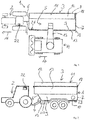
- Fig. 1 and 2 schematically show a train 1 from a towing vehicle 2 and an agricultural transport vehicle 3 pulled by the towing vehicle 3.
- the transport vehicle 3 is coupled via a drawbar, preferably via a so-called articulated drawbar 4, to the towing vehicle 2 and movable by the towing vehicle 2.
- the arrow 16 of Fig. 1 illustrates the direction of movement of the train 1 and thus the agricultural trolley. 3
- FIG. 1 and Fig. 2 show a drawn from a towing vehicle 2, agricultural trolley 3, the invention is not limited to such transport vehicles. The invention can also be used in self-propelled trolley.
- the agricultural trolley 3 has a loading space 5, which is bounded by a front wall 6, a rear wall 7, side walls 8 and 9 and a bottom wall 10. Opposite to the bottom wall 10, the trolley 3, a cargo space cover 11, wherein the cargo space cover 11, when the load compartment 5 of the trolley 3 is to be loaded from a harvesting vehicle 14, assumes an open position.
- Fig. 1 shows the harvesting vehicle 14, which has an ejection elbow 15, wherein the discharge elbow 15 serves to load the loading space 5 of the transport carriage 3.
- the harvesting vehicle 14 is moved laterally next to the trolley 3 in the harvesting direction shown by the arrow 17.
- the cargo compartment cover 11 has segments 12, 13.
- a first segment 12 is articulated on a first side wall 8, namely on an upper portion of the first side wall 8, whereas a second segment 13 of the cargo compartment cover 11 on the opposite second side wall 9 again at a upper section of the same is hinged.
- Fig. 3 shows the two segments 12, 13 of the cargo cover 11 in a position in which the cargo cover 11 is completely closed.
- Fig. 3 shows a closed position of the cargo space cover 11. In this closed position, the segments 12, 13 of the cargo space cover 11 extend approximately parallel or parallel to the bottom wall 10th
- Fig. 4 shows a known from practice opening position of the cargo compartment cover 11 with the segments 12, 13, wherein in Fig. 4 both segments 12, 13 of the cargo cover 11 are so fully opened that each of the segments 12, 13 relative to the closed position of the Fig. 3 is pivoted about 270 ° and 270 ° in a position in which the respective segment 12, 13 is laterally adjacent to the respective side wall 8, 9.
- the in Fig. 4 shown opening position of the cargo space cover 11 is selected for each possible loading operation of the trolley 3, that is independent of the relative position between the trolley 3 and the harvesting vehicle 14th
- an opening position of the load compartment cover 11 is selected as a function of the relative position between the trolley 3 and the harvesting vehicle 14.
- new opening positions of the cargo space cover 11 selected which then the cargo space cover 11 serves as a filling aid during the loading of the trolley 3, starting from the harvesting vehicle 14.
- the accuracy of the discharge chute 15 can be increased and the loading trolley 3 with crop starting from the harvesting vehicle 14 can be increased.
- one of the open positions of the cargo space cover 11 is according to for loading the trolley 3 Fig. 6 or Fig. 7 chosen, depending on which side of the trolley 3, the harvesting vehicle 14 is located.
- the harvesting vehicle 14 is laterally adjacent to the side wall 8 of the trolley 3, the opening position of the Fig. 6 selected.
- an opening position of the loading space cover 11 is selected for loading the transporting carriage 3, in which the segment 12 or 13 of the loading space cover 11, which faces away from the harvesting vehicle 14 side wall 8 or 9 of the trolley 3 is articulated, is partially opened so that a projection for the crop 14 to be loaded from the harvesting vehicle into the hold 5 crop is increased.
- FIG. 8 the known from the prior art opening position of the cargo compartment cover 11 and Fig. 9 shows one of the novel opening positions of the cargo cover 11, it can be seen that according to the prior art defined by the angle ⁇ projection surface for the crop to be loaded from the harvesting vehicle 14 is present, whereas using the novel opening position of Fig. 9 a significantly larger projection surface is present, which is defined by the angle ⁇ . As a result, the loading process of the trolley can be made much more effective.
- the in Fig. 5 shown opening position of the luggage compartment cover 11 is selected, in which the hinged on opposite side walls 8 and 9 segments 12, 13 of the luggage compartment cover 11 are partially open, in such a way that they are above the side walls 8, 9 of the trolley 3 and to the same connect funnel-shaped.
- the transport carriage 3 can be behind the harvesting vehicle 14 moves or is behind the harvesting vehicle 14, the loading process are designed to be particularly effective, namely by using the load compartment cover 11 as a loading aid or filling aid.
- the respective opening position of the load compartment cover 11, which is selected depending on the relative position between the trolley 3 and the harvesting vehicle 14 during loading, can be selected either operator side, in particular by the driver of the trolley 3, alternatively, the opening position of the luggage compartment cover 11 can also be selected automatically , Fig. 1 and 2 show an operating terminal 22 of the towing vehicle 2, on the operator side, the selection of the open position of the cargo compartment cover 11 can be selected.
- the automatic selection of the open position of the load compartment cover 11 can be effected, for example, by the fact that the trolley 3 has a sensor 23 with the aid of which the relative position between the trolley 3 and the harvesting vehicle 14 can be detected.
- This sensor 23 may be, for example, a camera, an ultrasonic, laser, radar sensor or the like.
- each segment 12, 13 of the luggage compartment cover 11 a drive 18 associated with the aid of which the respective segment 12, 13 of the cargo cover 11 can be moved.
- These drives 18 are preferably hydraulic drives, which can be supplied starting from a hydraulic block 20 with hydraulic oil, so as to hydraulically displace the segments 12, 13 of the cargo cover 11 and to keep in their defined open position.
- the control of the hydraulic block 20 is carried out starting from a control device 19 of the trolley 3.
- This control device 19 is preferably an electronic control device comprising means for performing the method described above.
- These resources are hardware resources and software resources.
- the hardware-side means are a processor for data processing, a memory for data storage and interfaces for data exchange with the modules involved in carrying out the method according to the invention, in particular with the drives 18 of the segments 12, 13 of the cargo cover 11.
- the software side Means are program modules.
- the control device 19 executes the method according to the invention on the control side. Accordingly, the control device 19 controls the drives 18 of the load compartment cover 11, namely the segments 12, 13 of the load compartment cover 11 depending on the relative position between the trolley 3 and the harvesting vehicle 14, for providing the respective of the relative position between the trolley 3 and the harvesting vehicle 14 dependent Opening position of the cargo compartment cover 11 at.
- Fig. 1 further shows a sensor 21 associated with the segment 13 of the cargo compartment cover 11, by means of which the position of this segment 13 of the cargo compartment cover 11 can be detected.
- the segment 12 of the cargo compartment cover 11 is associated with such a sensor 21, however, in Fig. 1 covered by the segment 12 and therefore not visible.
- the knowledge of the position of the segments 12, 13 of the cargo compartment cover 11 is necessary for driving the same in order to set the desired opening position of the cargo cover 11 exactly.
- the position of the segments 12, 13 may be made by detecting the time in which they are pivoting. Starting from a known starting position, the position of the segments 12, 13 can be calculated over the duration, speed and direction of the pivoting movement. If the segments 12, 13 are actuated via hydraulic actuators, it would be possible to deduce the respective position via the volume of the hydraulic fluid which was required for a pivoting movement.
- the segments 12, 13 of the cargo compartment cover 11 may alternatively be displaced or actuated by electric drives.
- the driver of the harvesting vehicle 14 can be relieved. Furthermore, the driver of the trolley 3 can be relieved.
- the entire loading process the trolley 3 starting from the harvesting vehicle 14 can be made more effective. When loading less crop is lost, the pollution of the trolley 3 is reduced. Furthermore, a better, more uniform loading of the trolley 3 can be ensured.
- the loading volume of the hold 5 can be optimally utilized. The number of transports between the field in which the crop is harvested and a collection point for the crop can be reduced. This can advantageously save fuel and pollutant discharge can be reduced.
Landscapes
- Engineering & Computer Science (AREA)
- Mechanical Engineering (AREA)
- Life Sciences & Earth Sciences (AREA)
- Environmental Sciences (AREA)
- Guiding Agricultural Machines (AREA)
- Agricultural Machines (AREA)
Description
Die Erfindung betrifft ein Verfahren zum Betreiben eines landwirtschaftlichen Transportwagens nach dem Oberbegriff des Anspruchs 1. Des Weiteren betrifft die Erfindung eine Steuerungseinrichtung zum Betreiben eines landwirtschaftlichen Transportwagens und einen landwirtschaftlichen Transportwagen.The invention relates to a method for operating an agricultural transport vehicle according to the preamble of claim 1. Furthermore, the invention relates to a control device for operating an agricultural transport vehicle and an agricultural transport vehicle.
Ein landwirtschaftlicher Transportwagen, bei welchem es sich um von einem Zugfahrzeug gezogenen Transportwagen oder auch um einen selbstfahrenden Transportwagen handeln kann, verfügt über einen Laderaum, welcher der Aufnahme von Erntegut dient. Der Laderaum des Transportwagens wird von einer Vorderwand des Transportwagens, einer Rückwand des Transportwagens, sich zwischen der Vorderwand und der Rückwand erstreckenden Seitenwänden des Transportwagens und einer Bodenwand desselben begrenzt. An einer Oberseite des Transportwagens gegenüberliegend zur Bodenwand desselben verfügt ein Transportwagen über eine sogenannte Laderaumabdeckung. Dann, wenn der Transportwagen beladen werden soll, ist die Laderaumabdeckung geöffnet. Dann hingegen, wenn der Transportwagen vollständig beladen ist und zum Beispiel auf einer Straße zu einer Sammelstelle für das Erntegut transportiert werden soll, ist die Laderaumabdeckung typischerweise geschlossen.An agricultural transport vehicle, which may be a towed by a towing vehicle or even a self-propelled trolley, has a cargo space, which serves to receive crop. The loading space of the trolley is limited by a front wall of the trolley, a rear wall of the trolley, between the front wall and the rear wall extending side walls of the trolley and a bottom wall thereof. At a top of the trolley opposite to the bottom wall of the same, a trolley has a so-called load compartment cover. Then, when the dolly is to be loaded, the tonneau cover is opened. Then, however, when the trolley is completely loaded and is to be transported, for example, on a road to a collection point for the crop, the load compartment cover is typically closed.
Beim Beladen des landwirtschaftlichen Transportwagens ausgehend von einem Erntefahrzeug, wie zum Beispiel ausgehend von einem Feldhäcksler, sind sowohl das Erntefahrzeug als auch der Transportwagen in Bewegung. Um möglichst wenig Erntegut beim Beladevorgang zu verlieren und den Transportwagen möglichst effektiv zu beladen, muss während des Beladevorgangs der Fahrer des Erntefahrzeugs stetig die Relativposition zum Transportwagen überwachen und entsprechend die Auswurfrichtung eines Auswurfkrümmers des Erntefahrzeugs anpassen. Dabei ist die Beladung des Transportwagens stark vom Geschick des Fahrers des Erntefahrzeugs abhängig.When loading the agricultural trolley from a harvesting vehicle, such as from a forage harvester, both the harvesting vehicle and the trolley are in motion. In order to lose as little crop as possible during loading and to load the trolley as effectively as possible, during the loading process, the driver of the harvesting vehicle constantly monitor the relative position to the trolley and adjust accordingly the direction of ejection of a discharge chute of the harvesting vehicle. The loading of the trolley is heavily dependent on the skill of the driver of the harvesting vehicle.
Aus der
Aus
Es besteht Bedarf an einem Verfahren zum Betreiben eines landwirtschaftlichen Transportwagens, an einer Steuerungseinrichtung zur Durchführung des Verfahrens und an einem Transportwagen, mit Hilfe deren der Beladevorgang verbessert werden kann.There is a need for a method for operating an agricultural trolley, a control device for carrying out the method and a trolley, by means of which the loading process can be improved.
Hiervon ausgehend liegt der vorliegenden Erfindung die Aufgabe zugrunde, ein neuartiges Verfahren zum Betreiben eines landwirtschaftlichen Transportwagens, eine entsprechende Steuerungseinrichtung und einen Transportwagen zu schaffen.On this basis, the present invention has the object to provide a novel method for operating an agricultural transport vehicle, a corresponding control device and a trolley.
Diese Aufgabe wird durch ein Verfahren zum Betreiben eines landwirtschaftlichen Transportwagens nach Anspruch 1 gelöst.This object is achieved by a method for operating an agricultural transport vehicle according to claim 1.
Erfindungsgemäß wird eine Öffnungsstellung der Laderaumabdeckung abhängig von einer Relativposition zwischen dem Transportwagen und dem Erntefahrzeug gewählt.According to the invention, an open position of the cargo compartment cover is selected as a function of a relative position between the transport vehicle and the harvesting vehicle.
Mit der hier vorliegenden Erfindung wird erstmals vorgeschlagen, die Laderaumabdeckung eines landwirtschaftlichen Transportwagens als Befüllhilfe beim Beladen des Transportwagens zu nutzen. Die Öffnungsstellung der Laderaumabdeckung wird abhängig von einer Relativposition zwischen dem Transportwagen und dem Erntefahrzeug gewählt. Dabei kann die Laderaumabdeckung abhängig von der Relativposition zwischen dem Transportwagen und dem Erntefahrzeug eine individuell angepasste Öffnungsstellung einnehmen, wodurch die Treffsicherheit für das Erntegut während der Beladung des Transportwagens ausgehend vom Erntefahrzeug erhöht und demnach die Beladung des Transportwagens effektiver gestaltet werden kann. Ferner kann der Fahrer des Erntefahrzeugs entlastet werden.With the present invention, it is proposed for the first time to use the loading space cover of an agricultural transport vehicle as a filling aid when loading the transport vehicle. The opening position of the cargo space cover is selected depending on a relative position between the trolley and the harvesting vehicle. The load compartment cover can depend on the relative position between the trolley and the harvesting vehicle occupy an individually adjusted opening position, whereby the accuracy of the harvested crop during loading of the trolley, starting from the harvesting vehicle increases and therefore the loading of the trolley can be made more effective. Furthermore, the driver of the harvesting vehicle can be relieved.
Gemäß der Erfindung wird dann, wenn das Erntefahrzeug sich seitlich neben dem Transportwagen befindet, für das Beladen des Transportwagens eine Öffnungsstellung der Laderaumabdeckung gewählt, in der ein Segment der Laderaumabdeckung, das an einer von dem Erntefahrzeug abgewandten Seitenwand des Transportwagens angelenkt ist, derart teilweise geöffnet ist, dass eine Projektionsfläche für das vom Erntefahrzeug aus zu beladende Erntegut vergrößert ist. In dieser Öffnungsstellung ist das Segment der Laderaumabdeckung, das an der vom Erntefahrzeug abgewandten Seitenwand angelenkt ist, oberhalb derselben positioniert und in Richtung auf eine dem Erntefahrzeug zugewandte Seitenwand geneigt. Vorzugsweise ist in dieser Öffnungsstellung ein Segment der Laderaumabdeckung, das an der dem Erntefahrzeug zugewandten Seitenwand des Transportwagens angelenkt ist, zumindest so weit geöffnet, dass dasselbe seitlich neben der dem Erntefahrzeug zugewandten Seitenwand positioniert ist. Diese Weiterbildung der Erfindung ermöglicht in einem sogenannten seitlichen Fahrbetrieb des Transportwagens, in welche derselbe an einer Seite des Erntefahrzeugs neben demselben fährt, besonders effektiv gestaltet werden.According to the invention, when the harvester is laterally adjacent to the trolley, an open position of the tonneau cover is selected for loading the trolley in which a segment of the tonneau cover hinged to a side wall of the trolley facing away from the harvester is partially opened is that a projection for the crop to be loaded from the harvested crop is increased. In this open position, the segment of the load compartment cover, which is articulated on the side wall facing away from the harvesting vehicle, positioned above it and inclined in the direction of a side wall facing the harvesting vehicle. Preferably, in this open position, a segment of the cargo compartment cover, which is articulated on the side wall of the transport vehicle facing the harvesting vehicle, is opened at least so far that it is positioned laterally next to the side wall facing the harvesting vehicle. This development of the invention allows in a so-called lateral driving operation of the trolley, in which the same goes on one side of the harvesting vehicle next to the same, be designed particularly effective.
Erfindungsgemäß wird dann, wenn der Transportwagen sich hinter dem Erntefahrzeug befindet, für das Beladen des Transportwagens eine Öffnungsstellung der Laderaumabdeckung gewählt, in der sich an gegenüberliegenden Seitenwänden des Transportwagens angelenkte Segmente der Laderaumabdeckung derart teilweise geöffnet sind, dass dieselben oberhalb der Seitenwände des Transportwagens positioniert sind und sich an dieselben trichterförmig anschließen. In dieser Öffnungsstellung divergieren die Segmente der Laderaumabdeckung ausgehend von dem an die Seitenwände angelenkten Enden in Richtung auf gegenüberliegende Enden derselben. Nach dieser Weiterbildung der Erfindung kann das Beladen des Transportwagens dann, wenn derselbe in einem sogenannten Anhäckselbetrieb hinter dem Erntefahrzeug fährt, besonders effektiv gestaltet werden.According to the invention, when the trolley is located behind the harvesting vehicle, an open position of the load compartment cover is selected for loading the trolley, in which segments of the load compartment cover hinged on opposite side walls of the trolley are partially opened such that they are positioned above the side walls of the trolley and connect to the same funnel-shaped. In this open position, the segments of the cargo compartment cover diverging from the hinged to the side walls ends towards opposite ends thereof. After this Development of the invention, the loading of the trolley then, when the same travels in a so-called Anhäckselbetrieb behind the harvesting vehicle, are designed to be particularly effective.
Die Steuerungseinrichtung zum Betreiben des landwirtschaftlichen Transportwagens ist in Anspruch 8 definiert. Der landwirtschaftliche Transportwagen ist in Anspruch 9 definiert.The control device for operating the agricultural transport vehicle is defined in
Bevorzugte Weiterbildungen der Erfindung ergeben sich aus den Unteransprüchen und der nachfolgenden Beschreibung. Ausführungsbeispiele der Erfindung werden, ohne hierauf beschränkt zu sein, an Hand der Zeichnung näher erläutert. Dabei zeigen:
- Fig. 1
- eine Draufsicht auf ein landwirtschaftliches Zuggespann bestehend aus einem landwirtschaftlichen Transportwagen und einem landwirtschaftlichen Zugfahrzeug zusammen mit einem Erntefahrzeug, welches den landwirtschaftlichen Transportwagen belädt;
- Fig. 2
- eine Seitenansicht des landwirtschaftlichen Zuggespanns bestehend aus dem landwirtschaftlichen Transportwagen und dem landwirtschaftlichen Zugfahrzeug;
- Fig. 3 bis 7
- unterschiedliche Positionen einer Laderaumabdeckung des landwirtschaftlichen Transportwagens; und
- Fig. 8 und 9
- die Positionen der Laderaumabdeckung gemäß
Fig. 4 und 7 zusammen mit einem Ende eines Auswurfkrümmers des Erntefahrzeugs.
- Fig. 1
- a plan view of an agricultural train combination consisting of an agricultural transport vehicle and an agricultural towing vehicle together with a harvesting vehicle which loads the agricultural transport vehicle;
- Fig. 2
- a side view of the agricultural train combination consisting of the agricultural transport vehicle and the agricultural towing vehicle;
- Fig. 3 to 7
- different positions of a cargo compartment cover of the agricultural transport vehicle; and
- 8 and 9
- the positions of the cargo compartment cover according to
4 and 7 together with one end of a discharge chute of the harvesting vehicle.
Die Erfindung betrifft ein Verfahren zum Betreiben eines landwirtschaftlichen Transportwagens. Ferner betrifft die Erfindung eine Steuerungseinrichtung zur Durchführung des Verfahrens sowie einen landwirtschaftlichen Transportwagen.The invention relates to a method for operating an agricultural transport vehicle. Furthermore, the invention relates to a control device for carrying out the method and an agricultural transport vehicle.
Obwohl
Der landwirtschaftliche Transportwagen 3 verfügt über einen Laderaum 5, der von einer Vorderwand 6, einer Rückwand 7, Seitenwänden 8 und 9 sowie einer Bodenwand 10 begrenzt ist. Gegenüberliegend zur Bodenwand 10 weist der Transportwagen 3 eine Laderaumabdeckung 11 auf, wobei die Laderaumabdeckung 11 dann, wenn der Laderaum 5 des Transportwagens 3 ausgehend von einem Erntefahrzeug 14 beladen werden soll, eine Öffnungsstellung einnimmt.The
Die Laderaumabdeckung 11 verfügt über Segmente 12, 13. Ein erstes Segment 12 ist an einer ersten Seitenwand 8, nämlich an einem oberen Abschnitt der ersten Seitenwand 8 angelenkt, wohingegen ein zweites Segment 13 der Laderaumabdeckung 11 an der gegenüberliegenden zweiten Seitenwand 9 ebenfalls wiederum an einem oberen Abschnitt derselben angelenkt ist.The
Erfindungsgemäß wird vorgeschlagen, eine Öffnungsstellung der Laderaumabdeckung 11 abhängig von der Relativposition zwischen dem Transportwagen 3 und dem Erntefahrzeug 14 zu wählen. Dabei wird insbesondere abhängig von der Relativposition zwischen dem Transportwagen 3 und dem Erntefahrzeug 14 eine der in
Dann, wenn das Erntefahrzeug 14 seitlich neben dem Transportwagen 3 fährt und sich damit während des Beladevorgangs seitlich neben dem Transportwagen 3 befindet, wird für das Beladen des Transportwagens 3 eine der Öffnungsstellungen der Laderaumabdeckung 11 gemäß
Befindet sich das Erntefahrzeug 14 seitlich neben der Seitenwand 9 (siehe
Befindet sich hingegen das Erntefahrzeug 14 seitlich neben der Seitenwand 8 des Transportwagens 3, so wird die Öffnungsstellung der
Dann, wenn das Erntefahrzeug 14 sich demnach seitlich neben dem Transportwagen 3 befindet, wird für das Beladen des Transportwagens 3 eine Öffnungsstellung der Laderaumabdeckung 11 gewählt, in der das Segment 12 bzw. 13 der Laderaumabdeckung 11, das an der von dem Erntefahrzeug 14 abgewandten Seitenwand 8 bzw. 9 des Transportwagens 3 angelenkt ist, derart teilweise geöffnet ist, dass eine Projektionsfläche für das vom Erntefahrzeug 14 aus in den Laderaum 5 zu beladende Erntegut vergrößert ist. In dieser Öffnungsstellung ist das Segment 12 bzw. 13 der Laderaumabdeckung 11, das an der vom Erntefahrzeug 14 abgewandten Seitendwand 8 bzw. 9 angelenkt ist, oberhalb dieser Seitenwand 8 bzw. 9 positioniert und in Richtung auf die dem Erntefahrzeug 14 zugewandte Seitenwand geneigt.Then, when the
Ferner ist in dieser Öffnungsstellung das andere Segment 13 bzw. 12 der Laderaumabdeckung 11, das an der dem Erntefahrzeug zugewandten Seitenwand 9 bzw. 8 des Transportwagens 3 angelenkt ist, zumindest soweit geöffnet, dass dasselbe sich seitlich neben der dem Erntefahrzeug 14 zugewandten Seitenwand 9 positioniert ist, vorzugsweise ist hierbei das an der dem Erntefahrzeug zugewandten Seitenwand 9 bzw. 8 des Transportwagens 3 angelenkte Segment 13 bzw. 12 der Laderaumabdeckung 11 vollständig geöffnet.Further, in this open position, the
Einem Vergleich der
Dann, wenn in einem sogenannten Anhäckselbetrieb sich der Transportwagen 3 hinter dem Erntefahrzeug 14 befindet, wird für das Beladen des Transportwagens 3 die in
Die jeweilige Öffnungsstellung der Laderaumabdeckung 11, die abhängig von der Relativposition zwischen dem Transportwagen 3 und dem Erntefahrzeug 14 während des Beladevorgangs gewählt wird, kann entweder bedienerseitig ausgewählt werden, insbesondere vom Fahrer des Transportwagens 3, alternativ kann die Öffnungsstellung der Laderaumabdeckung 11 auch automatisch ausgewählt werden.
Die automatische Auswahl der Öffnungsstellung der Laderaumabdeckung 11 kann zum Beispiel dadurch erfolgen, dass der Transportwagen 3 einen Sensor 23 aufweist, mit Hilfe dessen die Relativposition zwischen dem Transportwagen 3 und dem Erntefahrzeug 14 erfasst werden kann. Bei diesem Sensor 23 kann es sich zum Beispiel um eine Kamera, einen Ultraschall-, Laser-, Radarsensor oder dergleichen handeln.The automatic selection of the open position of the
Unabhängig davon, wie die von der Relativposition zwischen den Transportwagen 3 und dem Erntefahrzeug 14 abhängige Öffnungsstellung der Laderaumabdeckung 11 ausgewählt wird, wird dieselbe vorzugsweise automatisch eingestellt.Regardless of how the dependent on the relative position between the
Zur Einstellung der von der Relativposition zwischen dem Transportwagen 3 und dem Erntefahrzeug 14 abhängigen Öffnungsstellung der Laderaumabdeckung 11 ist jedem Segment 12, 13 der Laderaumabdeckung 11 ein Antrieb 18 zugeordnet, mit Hilfe dessen das jeweilige Segment 12, 13 der Laderaumabdeckung 11 verlagert werden kann. Bei diesen Antrieben 18 handelt es sich vorzugsweise um Hydraulikantriebe, die ausgehend von einem Hydraulikblock 20 aus mit Hydrauliköl versorgt werden können, um so die Segmente 12, 13 der Laderaumabdeckung 11 hydraulisch zu verlagern und in ihrer definierten Öffnungsstellung zu halten.To set the dependent on the relative position between the
Die Ansteuerung des Hydraulikblocks 20 erfolgt ausgehend von einer Steuerungseinrichtung 19 des Transportwagens 3. Bei dieser Steuerungseinrichtung 19 handelt es sich vorzugsweise um eine elektronische Steuerungseinrichtung, die Mittel zur Durchführung des oben beschriebenen Verfahrens umfasst. Bei diesen Mitteln handelt es sich um hardwareseitige Mittel und um softwareseitige Mittel.The control of the hydraulic block 20 is carried out starting from a
Bei den hardwareseitigen Mitteln handelt es sich um einen Prozessor zur Datenverarbeitung, einen Speicher zur Datenspeicherung und um Schnittstellen zum Datenaustausch mit den an der Durchführung des erfindungsgemäßen Verfahrens beteiligten Baugruppen, insbesondere mit den Antrieben 18 der Segmente 12, 13 der Laderaumabdeckung 11. Bei den softwareseitigen Mitteln handelt es sich um Programmbausteine.The hardware-side means are a processor for data processing, a memory for data storage and interfaces for data exchange with the modules involved in carrying out the method according to the invention, in particular with the
Die Steuerungseinrichtung 19 führt das erfindungsgemäße Verfahren steuerungsseitig aus. Die Steuerungseinrichtung 19 steuert demnach abhängig von der Relativposition zwischen dem Transportwagen 3 und dem Erntefahrzeug 14 die Antriebe 18 der Laderaumabdeckung 11, nämlich der Segmente 12, 13 der Laderaumabdeckung 11, zur Bereitstellung der jeweiligen von der Relativposition zwischen dem Transportwagen 3 und dem Erntefahrzeug 14 abhängigen Öffnungsstellung der Laderaumabdeckung 11 an.The
Die Segmente 12, 13 der Laderaumabdeckung 11 können alternativ durch elektrische Antriebe verlagert bzw. betätigt werden.The
Mit der Erfindung kann der Fahrer des Erntefahrzeugs 14 entlastet werden. Ferner kann der Fahrer des Transportwagens 3 entlastet werden. Der gesamte Beladevorgang des Transportwagens 3 ausgehend vom Erntefahrzeug 14 kann effektiver gestaltet werden. Beim Beladen geht weniger Erntegut verloren, die Verschmutzung des Transportwagens 3 wird reduziert. Ferner kann eine bessere, gleichmäßigere Beladung des Transportwagens 3 gewährleistet werden. Das Ladevolumen des Laderaums 5 kann optimal ausgenutzt werden. Die Anzahl von Transporten zwischen dem Feld, in welchem das Erntegut geerntet wird, und einem Sammelplatz für das Erntegut kann reduziert werden. Dadurch kann vorteilhaft Treibstoff eingespart und der Schadstoffaustrag vermindert werden.With the invention, the driver of the
- 11
- ZuggespannZuggespann
- 22
- Zugfahrzeugtowing vehicle
- 33
- TransportwagenDolly
- 44
- (Knick-)Deichsel(Buckling) Pedestrian
- 55
- Laderaumhold
- 66
- Vorderwandfront wall
- 77
- Rückwandrear wall
- 88th
- SeitenwandSide wall
- 99
- SeitenwandSide wall
- 1010
- Bodenwandbottom wall
- 1111
- LaderaumabdeckungTonneau cover
- 1212
- Segmentsegment
- 1313
- Segmentsegment
- 1414
- Erntefahrzeugharvester
- 1515
- Auswurfkrümmerchute
- 1616
- Fahrtrichtungdirection of travel
- 1717
- Fahrtrichtungdirection of travel
- 1818
- Antriebdrive
- 1919
- Steuerungseinrichtungcontrol device
- 2020
- Hydraulikblockhydraulic block
- 2121
- Sensorsensor
- 2222
- Bedienterminaloperating terminal
- 2323
- Sensorsensor
Claims (13)
- A method for operating an agricultural transport wagon (3) which is drawn by a tractor vehicle (2) or is self-propelled, wherein, when a loading space cover (11) of the transport wagon (3) is open, a loading space (5) of the transport wagon (3) is loaded with harvested produce from a harvesting vehicle (14) travelling adjacent to the transport wagon (3) and the loading space (5) is delimited by a front wall (6), a rear wall (7), side walls (8, 9) as well as a floor wall (10), characterized in that the loading space cover (11) is provided with a first segment (12) articulated to an upper section of the first side wall (8) as well as a second segment (13) articulated to an upper section of the opposing second side wall (9) and an opening position of the loading space cover (11) is selected as a function of a relative position between the transport wagon (3) and the harvesting vehicle (14), wherein when the harvesting vehicle (14) is positioned alongside the transport wagon (3), in order to load the transport wagon (3), an opening position of the loading space cover (11) is selected in which the segment (12, 13) of the loading space cover (11) which is articulated to the side wall (8) of the transport wagon (3) facing away from the harvesting vehicle (14) is partially opened in a manner such that a projection area for the harvested produce to be loaded from the harvesting vehicle (14) is enlarged, and when the transport wagon (3) is positioned behind the harvesting vehicle (14), in order to load the transport wagon (3), an opening position of the space cover (11) is selected in which the segments (12, 13) of the space cover (11) articulated to the opposing side walls (8, 9) of the transport wagon (3) are partially opened in a manner such that they are positioned above the side walls (8, 9) of the transport wagon (3) and are joined thereto in the shape of a funnel.
- The method as claimed in claim 1, characterized in that when the harvesting vehicle (14) is positioned alongside the transport wagon (3), in this opening position the segment (12) of the loading space cover (11) which is articulated on the side wall facing away from the harvesting vehicle (14) is positioned above it and is inclined in the direction of a side wall facing the harvesting vehicle (14).
- The method as claimed in claim 1 or claim 2, characterized in that in the opening position in which the harvesting vehicle (14) is alongside the transport wagon (3), the segment (12, 13) of the loading space cover (11) which is articulated to a side wall (9) of the transport wagon (3) facing the harvesting vehicle (14) is opened up at least widely enough that it is positioned alongside the side wall (9) facing the harvesting vehicle (14).
- The method as claimed in claim 3, characterized in that the segment of the loading space cover (11) articulated to a side wall (9) of the transport wagon (3) facing the harvesting vehicle (14) is fully open.
- The method as claimed in claim 1, characterized in that in the opening position in which the transport wagon (3) is positioned behind the harvesting vehicle (14), the segments (12, 13) of the loading space cover diverge from the ends thereof articulated to the side walls in the direction of the opposite ends thereof.
- The method as claimed in one of claims 1 to 5, characterized in that the opening position of the loading space cover (11) is selected by the operator and adjusted automatically.
- The method as claimed in one of claims 1 to 5, characterized in that the opening position of the loading space cover (11) is selected automatically and adjusted automatically.
- A control device for carrying out the method as claimed in one of claims 1 to 7 wherein, as a function of a relative position between the transport wagon (3) and the harvesting vehicle (14), power units (18) of the segments (12, 13) of the loading space cover (11) are actuated for controlled provision of the respective opening position of the loading space cover (11).
- An agricultural transport wagon (3) having a loading space cover (11) and having a control device (19) as claimed in claim 8.
- The agricultural transport wagon (3) as claimed in claim 9, characterized in that it comprises power units (18) for segments (12, 13) of the loading space cover (11) articulated to opposing side walls (8, 9) of the transport wagon (3).
- The agricultural transport wagon (3) as claimed in claim 10, characterized in that the power units (18) are hydraulic power units which can be supplied with hydraulic oil from a hydraulic block (20) or which are electrical power units.
- The agricultural transport wagon (3) as claimed in one of claims 9 to 11, characterized in that it comprises at least one sensor (21) for detecting the position of segments (12, 13) of the loading space cover (11) articulated to opposing side walls (8, 9) of the transport wagon (3).
- The agricultural transport wagon (3) as claimed in one of claims 9 to 12, characterized in that it comprises at least one sensor (23) for detecting the relative position between the transport wagon (3) and the harvesting vehicle (14).
Applications Claiming Priority (1)
| Application Number | Priority Date | Filing Date | Title |
|---|---|---|---|
| DE102016116461.5A DE102016116461A1 (en) | 2016-09-02 | 2016-09-02 | Method and control device for operating an agricultural transport vehicle and transport trolley |
Publications (2)
| Publication Number | Publication Date |
|---|---|
| EP3289853A1 EP3289853A1 (en) | 2018-03-07 |
| EP3289853B1 true EP3289853B1 (en) | 2019-03-27 |
Family
ID=59713951
Family Applications (1)
| Application Number | Title | Priority Date | Filing Date |
|---|---|---|---|
| EP17188213.7A Active EP3289853B1 (en) | 2016-09-02 | 2017-08-28 | Method and control device for operating an agricultural transport vehicle and transport vehicle |
Country Status (2)
| Country | Link |
|---|---|
| EP (1) | EP3289853B1 (en) |
| DE (1) | DE102016116461A1 (en) |
Cited By (33)
| Publication number | Priority date | Publication date | Assignee | Title |
|---|---|---|---|---|
| US11079725B2 (en) | 2019-04-10 | 2021-08-03 | Deere & Company | Machine control using real-time model |
| US11178818B2 (en) | 2018-10-26 | 2021-11-23 | Deere & Company | Harvesting machine control system with fill level processing based on yield data |
| US11234366B2 (en) | 2019-04-10 | 2022-02-01 | Deere & Company | Image selection for machine control |
| US11240961B2 (en) | 2018-10-26 | 2022-02-08 | Deere & Company | Controlling a harvesting machine based on a geo-spatial representation indicating where the harvesting machine is likely to reach capacity |
| US20220110251A1 (en) | 2020-10-09 | 2022-04-14 | Deere & Company | Crop moisture map generation and control system |
| US11467605B2 (en) | 2019-04-10 | 2022-10-11 | Deere & Company | Zonal machine control |
| US11474523B2 (en) | 2020-10-09 | 2022-10-18 | Deere & Company | Machine control using a predictive speed map |
| US11477940B2 (en) | 2020-03-26 | 2022-10-25 | Deere & Company | Mobile work machine control based on zone parameter modification |
| US11592822B2 (en) | 2020-10-09 | 2023-02-28 | Deere & Company | Machine control using a predictive map |
| US11589509B2 (en) | 2018-10-26 | 2023-02-28 | Deere & Company | Predictive machine characteristic map generation and control system |
| US11635765B2 (en) | 2020-10-09 | 2023-04-25 | Deere & Company | Crop state map generation and control system |
| US11641800B2 (en) | 2020-02-06 | 2023-05-09 | Deere & Company | Agricultural harvesting machine with pre-emergence weed detection and mitigation system |
| US11650587B2 (en) | 2020-10-09 | 2023-05-16 | Deere & Company | Predictive power map generation and control system |
| US11653588B2 (en) | 2018-10-26 | 2023-05-23 | Deere & Company | Yield map generation and control system |
| US11672203B2 (en) | 2018-10-26 | 2023-06-13 | Deere & Company | Predictive map generation and control |
| US11675354B2 (en) | 2020-10-09 | 2023-06-13 | Deere & Company | Machine control using a predictive map |
| US11711995B2 (en) | 2020-10-09 | 2023-08-01 | Deere & Company | Machine control using a predictive map |
| US11727680B2 (en) | 2020-10-09 | 2023-08-15 | Deere & Company | Predictive map generation based on seeding characteristics and control |
| US11778945B2 (en) | 2019-04-10 | 2023-10-10 | Deere & Company | Machine control using real-time model |
| US11825768B2 (en) | 2020-10-09 | 2023-11-28 | Deere & Company | Machine control using a predictive map |
| US11844311B2 (en) | 2020-10-09 | 2023-12-19 | Deere & Company | Machine control using a predictive map |
| US11845449B2 (en) | 2020-10-09 | 2023-12-19 | Deere & Company | Map generation and control system |
| US11849672B2 (en) | 2020-10-09 | 2023-12-26 | Deere & Company | Machine control using a predictive map |
| US11849671B2 (en) | 2020-10-09 | 2023-12-26 | Deere & Company | Crop state map generation and control system |
| US11864483B2 (en) | 2020-10-09 | 2024-01-09 | Deere & Company | Predictive map generation and control system |
| US11874669B2 (en) | 2020-10-09 | 2024-01-16 | Deere & Company | Map generation and control system |
| US11889787B2 (en) | 2020-10-09 | 2024-02-06 | Deere & Company | Predictive speed map generation and control system |
| US11889788B2 (en) | 2020-10-09 | 2024-02-06 | Deere & Company | Predictive biomass map generation and control |
| US11895948B2 (en) | 2020-10-09 | 2024-02-13 | Deere & Company | Predictive map generation and control based on soil properties |
| US11927459B2 (en) | 2020-10-09 | 2024-03-12 | Deere & Company | Machine control using a predictive map |
| US11946747B2 (en) | 2020-10-09 | 2024-04-02 | Deere & Company | Crop constituent map generation and control system |
| US11957072B2 (en) | 2020-02-06 | 2024-04-16 | Deere & Company | Pre-emergence weed detection and mitigation system |
| US11983009B2 (en) | 2020-10-09 | 2024-05-14 | Deere & Company | Map generation and control system |
Family Cites Families (6)
| Publication number | Priority date | Publication date | Assignee | Title |
|---|---|---|---|---|
| DE102004011789A1 (en) | 2004-03-09 | 2005-09-29 | Claas Selbstfahrende Erntemaschinen Gmbh | Device for detecting a loading wagon |
| DE202008014981U1 (en) | 2008-11-12 | 2009-01-15 | B. Strautmann & Söhne GmbH u. Co. KG | Covering device for holds on trucks |
| IT1397524B1 (en) * | 2009-12-24 | 2013-01-16 | Bortolin Regina Di Pivetta Ivo & C S N C | COMMAND DEVICE TO OPEN AND CLOSE CASSONI IN THE OPEN SKY OF INDUSTRIAL VEHICLES |
| NL2005055C2 (en) * | 2010-07-08 | 2012-01-10 | Loonbedrijf Caris | VEHICLE, TRUCK AND METHOD FOR PROVIDING AN AGRICULTURAL PRODUCT TO A VEHICLE. |
| DE102011052688B4 (en) | 2011-08-12 | 2021-02-04 | Andreas Reichhardt | Method and system for filling transport vehicles with crops |
| DE202016104858U1 (en) * | 2016-09-02 | 2016-09-15 | Claas Saulgau Gmbh | Control device for operating an agricultural transport vehicle and trolley |
-
2016
- 2016-09-02 DE DE102016116461.5A patent/DE102016116461A1/en not_active Withdrawn
-
2017
- 2017-08-28 EP EP17188213.7A patent/EP3289853B1/en active Active
Non-Patent Citations (1)
| Title |
|---|
| None * |
Cited By (36)
| Publication number | Priority date | Publication date | Assignee | Title |
|---|---|---|---|---|
| US11589509B2 (en) | 2018-10-26 | 2023-02-28 | Deere & Company | Predictive machine characteristic map generation and control system |
| US11178818B2 (en) | 2018-10-26 | 2021-11-23 | Deere & Company | Harvesting machine control system with fill level processing based on yield data |
| US11672203B2 (en) | 2018-10-26 | 2023-06-13 | Deere & Company | Predictive map generation and control |
| US11240961B2 (en) | 2018-10-26 | 2022-02-08 | Deere & Company | Controlling a harvesting machine based on a geo-spatial representation indicating where the harvesting machine is likely to reach capacity |
| US11653588B2 (en) | 2018-10-26 | 2023-05-23 | Deere & Company | Yield map generation and control system |
| US11778945B2 (en) | 2019-04-10 | 2023-10-10 | Deere & Company | Machine control using real-time model |
| US11467605B2 (en) | 2019-04-10 | 2022-10-11 | Deere & Company | Zonal machine control |
| US11829112B2 (en) | 2019-04-10 | 2023-11-28 | Deere & Company | Machine control using real-time model |
| US11079725B2 (en) | 2019-04-10 | 2021-08-03 | Deere & Company | Machine control using real-time model |
| US11234366B2 (en) | 2019-04-10 | 2022-02-01 | Deere & Company | Image selection for machine control |
| US11650553B2 (en) | 2019-04-10 | 2023-05-16 | Deere & Company | Machine control using real-time model |
| US11957072B2 (en) | 2020-02-06 | 2024-04-16 | Deere & Company | Pre-emergence weed detection and mitigation system |
| US11641800B2 (en) | 2020-02-06 | 2023-05-09 | Deere & Company | Agricultural harvesting machine with pre-emergence weed detection and mitigation system |
| US11477940B2 (en) | 2020-03-26 | 2022-10-25 | Deere & Company | Mobile work machine control based on zone parameter modification |
| US11727680B2 (en) | 2020-10-09 | 2023-08-15 | Deere & Company | Predictive map generation based on seeding characteristics and control |
| US11849671B2 (en) | 2020-10-09 | 2023-12-26 | Deere & Company | Crop state map generation and control system |
| US11675354B2 (en) | 2020-10-09 | 2023-06-13 | Deere & Company | Machine control using a predictive map |
| US11711995B2 (en) | 2020-10-09 | 2023-08-01 | Deere & Company | Machine control using a predictive map |
| US11635765B2 (en) | 2020-10-09 | 2023-04-25 | Deere & Company | Crop state map generation and control system |
| US11592822B2 (en) | 2020-10-09 | 2023-02-28 | Deere & Company | Machine control using a predictive map |
| US11474523B2 (en) | 2020-10-09 | 2022-10-18 | Deere & Company | Machine control using a predictive speed map |
| US11825768B2 (en) | 2020-10-09 | 2023-11-28 | Deere & Company | Machine control using a predictive map |
| US11844311B2 (en) | 2020-10-09 | 2023-12-19 | Deere & Company | Machine control using a predictive map |
| US11845449B2 (en) | 2020-10-09 | 2023-12-19 | Deere & Company | Map generation and control system |
| US11849672B2 (en) | 2020-10-09 | 2023-12-26 | Deere & Company | Machine control using a predictive map |
| US11650587B2 (en) | 2020-10-09 | 2023-05-16 | Deere & Company | Predictive power map generation and control system |
| US11864483B2 (en) | 2020-10-09 | 2024-01-09 | Deere & Company | Predictive map generation and control system |
| US11871697B2 (en) | 2020-10-09 | 2024-01-16 | Deere & Company | Crop moisture map generation and control system |
| US11874669B2 (en) | 2020-10-09 | 2024-01-16 | Deere & Company | Map generation and control system |
| US11889787B2 (en) | 2020-10-09 | 2024-02-06 | Deere & Company | Predictive speed map generation and control system |
| US11889788B2 (en) | 2020-10-09 | 2024-02-06 | Deere & Company | Predictive biomass map generation and control |
| US11895948B2 (en) | 2020-10-09 | 2024-02-13 | Deere & Company | Predictive map generation and control based on soil properties |
| US11927459B2 (en) | 2020-10-09 | 2024-03-12 | Deere & Company | Machine control using a predictive map |
| US11946747B2 (en) | 2020-10-09 | 2024-04-02 | Deere & Company | Crop constituent map generation and control system |
| US20220110251A1 (en) | 2020-10-09 | 2022-04-14 | Deere & Company | Crop moisture map generation and control system |
| US11983009B2 (en) | 2020-10-09 | 2024-05-14 | Deere & Company | Map generation and control system |
Also Published As
| Publication number | Publication date |
|---|---|
| EP3289853A1 (en) | 2018-03-07 |
| DE102016116461A1 (en) | 2018-03-08 |
Similar Documents
| Publication | Publication Date | Title |
|---|---|---|
| EP3289853B1 (en) | Method and control device for operating an agricultural transport vehicle and transport vehicle | |
| EP3243374B1 (en) | Method and control device for operating an agricultural transport vehicle and transport vehicle | |
| EP3289852B1 (en) | Transport automobile | |
| AT520036B1 (en) | Loader wagons or trailers | |
| EP2829171B1 (en) | Self-propelled harvester and vehicle combination | |
| EP2302995A1 (en) | Control arrangement for controlling the transfer of agricultural crop from a harvesting machine to a transport vehicle | |
| DE102009047585A1 (en) | Combination of a towing vehicle and a device | |
| EP1645178A1 (en) | Transfer assistance system | |
| EP3837961B1 (en) | Combination of a towing vehicle and a device | |
| DE102011016743A1 (en) | Agricultural transport vehicle and vehicle network | |
| EP3633110B1 (en) | Method for controlling a charging tool | |
| DE202012103905U1 (en) | Mobile overload station for overloading cargo | |
| EP3208198A1 (en) | Device for transporting luggage items | |
| EP3095315A1 (en) | Method and control device for operating an agricultural loader wagon | |
| DE102015103688A1 (en) | Method for operating an agricultural loading wagon and control device | |
| DE202016104858U1 (en) | Control device for operating an agricultural transport vehicle and trolley | |
| EP3456584B1 (en) | Load transport vehicle and method for operating same | |
| DE19931281A1 (en) | Trolley for transporting a cutting unit | |
| AT517293B1 (en) | Method and control device for operating an agricultural loading wagon | |
| DE1755729A1 (en) | AGRICULTURAL CART | |
| DE2825198A1 (en) | MACHINE FOR HARVESTING AND COLLECTING PLANTS | |
| DE202007012649U1 (en) | wagon | |
| DE102016114379A1 (en) | Bale collecting vehicle for collecting and transporting round bales | |
| DE102016102226B4 (en) | Vehicle combination, especially for agricultural use | |
| AT320443B (en) | Structure for a loading wagon for the transport of agricultural bulk goods |
Legal Events
| Date | Code | Title | Description |
|---|---|---|---|
| PUAI | Public reference made under article 153(3) epc to a published international application that has entered the european phase |
Free format text: ORIGINAL CODE: 0009012 |
|
| STAA | Information on the status of an ep patent application or granted ep patent |
Free format text: STATUS: THE APPLICATION HAS BEEN PUBLISHED |
|
| AK | Designated contracting states |
Kind code of ref document: A1 Designated state(s): AL AT BE BG CH CY CZ DE DK EE ES FI FR GB GR HR HU IE IS IT LI LT LU LV MC MK MT NL NO PL PT RO RS SE SI SK SM TR |
|
| AX | Request for extension of the european patent |
Extension state: BA ME |
|
| STAA | Information on the status of an ep patent application or granted ep patent |
Free format text: STATUS: REQUEST FOR EXAMINATION WAS MADE |
|
| 17P | Request for examination filed |
Effective date: 20180907 |
|
| RBV | Designated contracting states (corrected) |
Designated state(s): AL AT BE BG CH CY CZ DE DK EE ES FI FR GB GR HR HU IE IS IT LI LT LU LV MC MK MT NL NO PL PT RO RS SE SI SK SM TR |
|
| RIC1 | Information provided on ipc code assigned before grant |
Ipc: A01D 43/07 20060101ALI20180928BHEP Ipc: A01D 90/02 20060101AFI20180928BHEP Ipc: A01D 90/12 20060101ALI20180928BHEP Ipc: B60J 7/00 20060101ALI20180928BHEP |
|
| GRAP | Despatch of communication of intention to grant a patent |
Free format text: ORIGINAL CODE: EPIDOSNIGR1 |
|
| STAA | Information on the status of an ep patent application or granted ep patent |
Free format text: STATUS: GRANT OF PATENT IS INTENDED |
|
| INTG | Intention to grant announced |
Effective date: 20181129 |
|
| GRAS | Grant fee paid |
Free format text: ORIGINAL CODE: EPIDOSNIGR3 |
|
| GRAA | (expected) grant |
Free format text: ORIGINAL CODE: 0009210 |
|
| STAA | Information on the status of an ep patent application or granted ep patent |
Free format text: STATUS: THE PATENT HAS BEEN GRANTED |
|
| AK | Designated contracting states |
Kind code of ref document: B1 Designated state(s): AL AT BE BG CH CY CZ DE DK EE ES FI FR GB GR HR HU IE IS IT LI LT LU LV MC MK MT NL NO PL PT RO RS SE SI SK SM TR |
|
| REG | Reference to a national code |
Ref country code: GB Ref legal event code: FG4D Free format text: NOT ENGLISH |
|
| REG | Reference to a national code |
Ref country code: CH Ref legal event code: EP |
|
| REG | Reference to a national code |
Ref country code: DE Ref legal event code: R096 Ref document number: 502017001004 Country of ref document: DE |
|
| REG | Reference to a national code |
Ref country code: AT Ref legal event code: REF Ref document number: 1111880 Country of ref document: AT Kind code of ref document: T Effective date: 20190415 |
|
| REG | Reference to a national code |
Ref country code: IE Ref legal event code: FG4D Free format text: LANGUAGE OF EP DOCUMENT: GERMAN |
|
| PG25 | Lapsed in a contracting state [announced via postgrant information from national office to epo] |
Ref country code: FI Free format text: LAPSE BECAUSE OF FAILURE TO SUBMIT A TRANSLATION OF THE DESCRIPTION OR TO PAY THE FEE WITHIN THE PRESCRIBED TIME-LIMIT Effective date: 20190327 Ref country code: LT Free format text: LAPSE BECAUSE OF FAILURE TO SUBMIT A TRANSLATION OF THE DESCRIPTION OR TO PAY THE FEE WITHIN THE PRESCRIBED TIME-LIMIT Effective date: 20190327 Ref country code: SE Free format text: LAPSE BECAUSE OF FAILURE TO SUBMIT A TRANSLATION OF THE DESCRIPTION OR TO PAY THE FEE WITHIN THE PRESCRIBED TIME-LIMIT Effective date: 20190327 Ref country code: NO Free format text: LAPSE BECAUSE OF FAILURE TO SUBMIT A TRANSLATION OF THE DESCRIPTION OR TO PAY THE FEE WITHIN THE PRESCRIBED TIME-LIMIT Effective date: 20190627 |
|
| REG | Reference to a national code |
Ref country code: NL Ref legal event code: MP Effective date: 20190327 |
|
| PG25 | Lapsed in a contracting state [announced via postgrant information from national office to epo] |
Ref country code: GR Free format text: LAPSE BECAUSE OF FAILURE TO SUBMIT A TRANSLATION OF THE DESCRIPTION OR TO PAY THE FEE WITHIN THE PRESCRIBED TIME-LIMIT Effective date: 20190628 Ref country code: BG Free format text: LAPSE BECAUSE OF FAILURE TO SUBMIT A TRANSLATION OF THE DESCRIPTION OR TO PAY THE FEE WITHIN THE PRESCRIBED TIME-LIMIT Effective date: 20190627 Ref country code: RS Free format text: LAPSE BECAUSE OF FAILURE TO SUBMIT A TRANSLATION OF THE DESCRIPTION OR TO PAY THE FEE WITHIN THE PRESCRIBED TIME-LIMIT Effective date: 20190327 Ref country code: NL Free format text: LAPSE BECAUSE OF FAILURE TO SUBMIT A TRANSLATION OF THE DESCRIPTION OR TO PAY THE FEE WITHIN THE PRESCRIBED TIME-LIMIT Effective date: 20190327 Ref country code: HR Free format text: LAPSE BECAUSE OF FAILURE TO SUBMIT A TRANSLATION OF THE DESCRIPTION OR TO PAY THE FEE WITHIN THE PRESCRIBED TIME-LIMIT Effective date: 20190327 Ref country code: LV Free format text: LAPSE BECAUSE OF FAILURE TO SUBMIT A TRANSLATION OF THE DESCRIPTION OR TO PAY THE FEE WITHIN THE PRESCRIBED TIME-LIMIT Effective date: 20190327 |
|
| PG25 | Lapsed in a contracting state [announced via postgrant information from national office to epo] |
Ref country code: SK Free format text: LAPSE BECAUSE OF FAILURE TO SUBMIT A TRANSLATION OF THE DESCRIPTION OR TO PAY THE FEE WITHIN THE PRESCRIBED TIME-LIMIT Effective date: 20190327 Ref country code: RO Free format text: LAPSE BECAUSE OF FAILURE TO SUBMIT A TRANSLATION OF THE DESCRIPTION OR TO PAY THE FEE WITHIN THE PRESCRIBED TIME-LIMIT Effective date: 20190327 Ref country code: IT Free format text: LAPSE BECAUSE OF FAILURE TO SUBMIT A TRANSLATION OF THE DESCRIPTION OR TO PAY THE FEE WITHIN THE PRESCRIBED TIME-LIMIT Effective date: 20190327 Ref country code: EE Free format text: LAPSE BECAUSE OF FAILURE TO SUBMIT A TRANSLATION OF THE DESCRIPTION OR TO PAY THE FEE WITHIN THE PRESCRIBED TIME-LIMIT Effective date: 20190327 Ref country code: PT Free format text: LAPSE BECAUSE OF FAILURE TO SUBMIT A TRANSLATION OF THE DESCRIPTION OR TO PAY THE FEE WITHIN THE PRESCRIBED TIME-LIMIT Effective date: 20190727 Ref country code: AL Free format text: LAPSE BECAUSE OF FAILURE TO SUBMIT A TRANSLATION OF THE DESCRIPTION OR TO PAY THE FEE WITHIN THE PRESCRIBED TIME-LIMIT Effective date: 20190327 Ref country code: CZ Free format text: LAPSE BECAUSE OF FAILURE TO SUBMIT A TRANSLATION OF THE DESCRIPTION OR TO PAY THE FEE WITHIN THE PRESCRIBED TIME-LIMIT Effective date: 20190327 Ref country code: ES Free format text: LAPSE BECAUSE OF FAILURE TO SUBMIT A TRANSLATION OF THE DESCRIPTION OR TO PAY THE FEE WITHIN THE PRESCRIBED TIME-LIMIT Effective date: 20190327 |
|
| PG25 | Lapsed in a contracting state [announced via postgrant information from national office to epo] |
Ref country code: PL Free format text: LAPSE BECAUSE OF FAILURE TO SUBMIT A TRANSLATION OF THE DESCRIPTION OR TO PAY THE FEE WITHIN THE PRESCRIBED TIME-LIMIT Effective date: 20190327 Ref country code: SM Free format text: LAPSE BECAUSE OF FAILURE TO SUBMIT A TRANSLATION OF THE DESCRIPTION OR TO PAY THE FEE WITHIN THE PRESCRIBED TIME-LIMIT Effective date: 20190327 |
|
| PG25 | Lapsed in a contracting state [announced via postgrant information from national office to epo] |
Ref country code: IS Free format text: LAPSE BECAUSE OF FAILURE TO SUBMIT A TRANSLATION OF THE DESCRIPTION OR TO PAY THE FEE WITHIN THE PRESCRIBED TIME-LIMIT Effective date: 20190727 |
|
| REG | Reference to a national code |
Ref country code: DE Ref legal event code: R097 Ref document number: 502017001004 Country of ref document: DE |
|
| PG25 | Lapsed in a contracting state [announced via postgrant information from national office to epo] |
Ref country code: DK Free format text: LAPSE BECAUSE OF FAILURE TO SUBMIT A TRANSLATION OF THE DESCRIPTION OR TO PAY THE FEE WITHIN THE PRESCRIBED TIME-LIMIT Effective date: 20190327 |
|
| PLBE | No opposition filed within time limit |
Free format text: ORIGINAL CODE: 0009261 |
|
| STAA | Information on the status of an ep patent application or granted ep patent |
Free format text: STATUS: NO OPPOSITION FILED WITHIN TIME LIMIT |
|
| PG25 | Lapsed in a contracting state [announced via postgrant information from national office to epo] |
Ref country code: SI Free format text: LAPSE BECAUSE OF FAILURE TO SUBMIT A TRANSLATION OF THE DESCRIPTION OR TO PAY THE FEE WITHIN THE PRESCRIBED TIME-LIMIT Effective date: 20190327 |
|
| 26N | No opposition filed |
Effective date: 20200103 |
|
| PG25 | Lapsed in a contracting state [announced via postgrant information from national office to epo] |
Ref country code: TR Free format text: LAPSE BECAUSE OF FAILURE TO SUBMIT A TRANSLATION OF THE DESCRIPTION OR TO PAY THE FEE WITHIN THE PRESCRIBED TIME-LIMIT Effective date: 20190327 |
|
| PG25 | Lapsed in a contracting state [announced via postgrant information from national office to epo] |
Ref country code: LU Free format text: LAPSE BECAUSE OF NON-PAYMENT OF DUE FEES Effective date: 20190828 Ref country code: MC Free format text: LAPSE BECAUSE OF FAILURE TO SUBMIT A TRANSLATION OF THE DESCRIPTION OR TO PAY THE FEE WITHIN THE PRESCRIBED TIME-LIMIT Effective date: 20190327 |
|
| PG25 | Lapsed in a contracting state [announced via postgrant information from national office to epo] |
Ref country code: FR Free format text: LAPSE BECAUSE OF NON-PAYMENT OF DUE FEES Effective date: 20190831 Ref country code: IE Free format text: LAPSE BECAUSE OF NON-PAYMENT OF DUE FEES Effective date: 20190828 |
|
| REG | Reference to a national code |
Ref country code: CH Ref legal event code: PL |
|
| PG25 | Lapsed in a contracting state [announced via postgrant information from national office to epo] |
Ref country code: LI Free format text: LAPSE BECAUSE OF NON-PAYMENT OF DUE FEES Effective date: 20200831 Ref country code: CH Free format text: LAPSE BECAUSE OF NON-PAYMENT OF DUE FEES Effective date: 20200831 |
|
| PG25 | Lapsed in a contracting state [announced via postgrant information from national office to epo] |
Ref country code: CY Free format text: LAPSE BECAUSE OF FAILURE TO SUBMIT A TRANSLATION OF THE DESCRIPTION OR TO PAY THE FEE WITHIN THE PRESCRIBED TIME-LIMIT Effective date: 20190327 |
|
| PG25 | Lapsed in a contracting state [announced via postgrant information from national office to epo] |
Ref country code: MT Free format text: LAPSE BECAUSE OF FAILURE TO SUBMIT A TRANSLATION OF THE DESCRIPTION OR TO PAY THE FEE WITHIN THE PRESCRIBED TIME-LIMIT Effective date: 20190327 Ref country code: HU Free format text: LAPSE BECAUSE OF FAILURE TO SUBMIT A TRANSLATION OF THE DESCRIPTION OR TO PAY THE FEE WITHIN THE PRESCRIBED TIME-LIMIT; INVALID AB INITIO Effective date: 20170828 |
|
| GBPC | Gb: european patent ceased through non-payment of renewal fee |
Effective date: 20210828 |
|
| PG25 | Lapsed in a contracting state [announced via postgrant information from national office to epo] |
Ref country code: MK Free format text: LAPSE BECAUSE OF FAILURE TO SUBMIT A TRANSLATION OF THE DESCRIPTION OR TO PAY THE FEE WITHIN THE PRESCRIBED TIME-LIMIT Effective date: 20190327 |
|
| PG25 | Lapsed in a contracting state [announced via postgrant information from national office to epo] |
Ref country code: GB Free format text: LAPSE BECAUSE OF NON-PAYMENT OF DUE FEES Effective date: 20210828 |
|
| P01 | Opt-out of the competence of the unified patent court (upc) registered |
Effective date: 20230508 |
|
| PGFP | Annual fee paid to national office [announced via postgrant information from national office to epo] |
Ref country code: AT Payment date: 20230822 Year of fee payment: 7 |
|
| PGFP | Annual fee paid to national office [announced via postgrant information from national office to epo] |
Ref country code: DE Payment date: 20230821 Year of fee payment: 7 Ref country code: BE Payment date: 20230821 Year of fee payment: 7 |