EP3286912B1 - Hybrid nanocomposite materials, laser scanning system and use thereof in volumetric image projection - Google Patents
Hybrid nanocomposite materials, laser scanning system and use thereof in volumetric image projection Download PDFInfo
- Publication number
- EP3286912B1 EP3286912B1 EP16782433.3A EP16782433A EP3286912B1 EP 3286912 B1 EP3286912 B1 EP 3286912B1 EP 16782433 A EP16782433 A EP 16782433A EP 3286912 B1 EP3286912 B1 EP 3286912B1
- Authority
- EP
- European Patent Office
- Prior art keywords
- matrix
- particles
- light
- nano
- scan
- Prior art date
- Legal status (The legal status is an assumption and is not a legal conclusion. Google has not performed a legal analysis and makes no representation as to the accuracy of the status listed.)
- Active
Links
- 239000000463 material Substances 0.000 title claims description 30
- 239000002114 nanocomposite Substances 0.000 title description 3
- 239000002245 particle Substances 0.000 claims description 58
- 239000002096 quantum dot Substances 0.000 claims description 55
- 239000011159 matrix material Substances 0.000 claims description 54
- 238000010521 absorption reaction Methods 0.000 claims description 34
- 238000000034 method Methods 0.000 claims description 33
- OKTJSMMVPCPJKN-UHFFFAOYSA-N Carbon Chemical compound [C] OKTJSMMVPCPJKN-UHFFFAOYSA-N 0.000 claims description 26
- 229920003229 poly(methyl methacrylate) Polymers 0.000 claims description 25
- 239000004926 polymethyl methacrylate Substances 0.000 claims description 24
- 239000000203 mixture Substances 0.000 claims description 21
- 239000002041 carbon nanotube Substances 0.000 claims description 19
- 229910021393 carbon nanotube Inorganic materials 0.000 claims description 19
- 239000000654 additive Substances 0.000 claims description 17
- 239000002105 nanoparticle Substances 0.000 claims description 16
- 239000007787 solid Substances 0.000 claims description 16
- 230000000996 additive effect Effects 0.000 claims description 15
- 238000003384 imaging method Methods 0.000 claims description 11
- 230000008569 process Effects 0.000 claims description 9
- 239000004065 semiconductor Substances 0.000 claims description 9
- 230000015572 biosynthetic process Effects 0.000 claims description 8
- 239000002159 nanocrystal Substances 0.000 claims description 8
- 229910052709 silver Inorganic materials 0.000 claims description 8
- 239000004332 silver Substances 0.000 claims description 8
- 238000003786 synthesis reaction Methods 0.000 claims description 8
- 229920001046 Nanocellulose Polymers 0.000 claims description 6
- 229920001940 conductive polymer Polymers 0.000 claims description 5
- PCHJSUWPFVWCPO-UHFFFAOYSA-N gold Chemical compound [Au] PCHJSUWPFVWCPO-UHFFFAOYSA-N 0.000 claims description 5
- 239000010931 gold Substances 0.000 claims description 5
- 229910052737 gold Inorganic materials 0.000 claims description 5
- 229910021389 graphene Inorganic materials 0.000 claims description 5
- 238000002156 mixing Methods 0.000 claims description 5
- 239000003505 polymerization initiator Substances 0.000 claims description 5
- 239000000178 monomer Substances 0.000 claims description 4
- 230000002708 enhancing effect Effects 0.000 claims description 3
- 239000011885 synergistic combination Substances 0.000 claims description 3
- 239000002055 nanoplate Substances 0.000 claims 2
- 229920000642 polymer Polymers 0.000 claims 1
- 230000002194 synthesizing effect Effects 0.000 claims 1
- 239000000523 sample Substances 0.000 description 49
- FOIXSVOLVBLSDH-UHFFFAOYSA-N Silver ion Chemical compound [Ag+] FOIXSVOLVBLSDH-UHFFFAOYSA-N 0.000 description 21
- 238000005424 photoluminescence Methods 0.000 description 17
- 230000000694 effects Effects 0.000 description 16
- 238000004519 manufacturing process Methods 0.000 description 12
- 229920003023 plastic Polymers 0.000 description 10
- 239000004033 plastic Substances 0.000 description 10
- XLYOFNOQVPJJNP-UHFFFAOYSA-N water Substances O XLYOFNOQVPJJNP-UHFFFAOYSA-N 0.000 description 10
- BQCADISMDOOEFD-UHFFFAOYSA-N Silver Chemical compound [Ag] BQCADISMDOOEFD-UHFFFAOYSA-N 0.000 description 9
- 230000009022 nonlinear effect Effects 0.000 description 8
- 230000003287 optical effect Effects 0.000 description 8
- 238000005498 polishing Methods 0.000 description 8
- 238000012360 testing method Methods 0.000 description 8
- 230000005284 excitation Effects 0.000 description 7
- 230000001965 increasing effect Effects 0.000 description 6
- 230000009021 linear effect Effects 0.000 description 6
- VVQNEPGJFQJSBK-UHFFFAOYSA-N Methyl methacrylate Chemical compound COC(=O)C(C)=C VVQNEPGJFQJSBK-UHFFFAOYSA-N 0.000 description 5
- 238000007792 addition Methods 0.000 description 5
- 238000002474 experimental method Methods 0.000 description 5
- 238000005259 measurement Methods 0.000 description 5
- 238000012512 characterization method Methods 0.000 description 4
- 238000005520 cutting process Methods 0.000 description 4
- 238000006073 displacement reaction Methods 0.000 description 4
- 239000000428 dust Substances 0.000 description 4
- 239000007788 liquid Substances 0.000 description 4
- 230000004044 response Effects 0.000 description 4
- 238000004458 analytical method Methods 0.000 description 3
- 238000010438 heat treatment Methods 0.000 description 3
- 238000001499 laser induced fluorescence spectroscopy Methods 0.000 description 3
- 241001080024 Telles Species 0.000 description 2
- 239000006096 absorbing agent Substances 0.000 description 2
- 230000002776 aggregation Effects 0.000 description 2
- 229910052782 aluminium Inorganic materials 0.000 description 2
- XAGFODPZIPBFFR-UHFFFAOYSA-N aluminium Chemical compound [Al] XAGFODPZIPBFFR-UHFFFAOYSA-N 0.000 description 2
- 238000011960 computer-aided design Methods 0.000 description 2
- 238000010586 diagram Methods 0.000 description 2
- 238000005516 engineering process Methods 0.000 description 2
- 210000000887 face Anatomy 0.000 description 2
- 239000011521 glass Substances 0.000 description 2
- 239000004973 liquid crystal related substance Substances 0.000 description 2
- 230000007246 mechanism Effects 0.000 description 2
- 229910052751 metal Inorganic materials 0.000 description 2
- 239000002184 metal Substances 0.000 description 2
- 239000013528 metallic particle Substances 0.000 description 2
- 239000003607 modifier Substances 0.000 description 2
- 239000002086 nanomaterial Substances 0.000 description 2
- 239000002071 nanotube Substances 0.000 description 2
- 239000012188 paraffin wax Substances 0.000 description 2
- 238000006116 polymerization reaction Methods 0.000 description 2
- 230000003068 static effect Effects 0.000 description 2
- 229920002972 Acrylic fiber Polymers 0.000 description 1
- 229910052684 Cerium Inorganic materials 0.000 description 1
- 241000287107 Passer Species 0.000 description 1
- 244000137852 Petrea volubilis Species 0.000 description 1
- 229920005372 Plexiglas® Polymers 0.000 description 1
- 241000206607 Porphyra umbilicalis Species 0.000 description 1
- 235000014443 Pyrus communis Nutrition 0.000 description 1
- 229920000297 Rayon Polymers 0.000 description 1
- 240000008042 Zea mays Species 0.000 description 1
- 230000004913 activation Effects 0.000 description 1
- 230000002730 additional effect Effects 0.000 description 1
- 238000005054 agglomeration Methods 0.000 description 1
- 238000004220 aggregation Methods 0.000 description 1
- 238000013459 approach Methods 0.000 description 1
- 239000011852 carbon nanoparticle Substances 0.000 description 1
- 229920002678 cellulose Polymers 0.000 description 1
- 239000001913 cellulose Substances 0.000 description 1
- GWXLDORMOJMVQZ-UHFFFAOYSA-N cerium Chemical compound [Ce] GWXLDORMOJMVQZ-UHFFFAOYSA-N 0.000 description 1
- 239000003086 colorant Substances 0.000 description 1
- 230000000052 comparative effect Effects 0.000 description 1
- 239000011365 complex material Substances 0.000 description 1
- 239000004020 conductor Substances 0.000 description 1
- 239000013068 control sample Substances 0.000 description 1
- 238000012937 correction Methods 0.000 description 1
- 230000002596 correlated effect Effects 0.000 description 1
- 230000000875 corresponding effect Effects 0.000 description 1
- 230000008878 coupling Effects 0.000 description 1
- 238000010168 coupling process Methods 0.000 description 1
- 238000005859 coupling reaction Methods 0.000 description 1
- 239000013078 crystal Substances 0.000 description 1
- 230000000254 damaging effect Effects 0.000 description 1
- 230000007547 defect Effects 0.000 description 1
- 238000013461 design Methods 0.000 description 1
- 229910003460 diamond Inorganic materials 0.000 description 1
- 239000010432 diamond Substances 0.000 description 1
- 239000006185 dispersion Substances 0.000 description 1
- 230000005684 electric field Effects 0.000 description 1
- 235000021183 entrée Nutrition 0.000 description 1
- 230000005281 excited state Effects 0.000 description 1
- 239000012530 fluid Substances 0.000 description 1
- 230000036541 health Effects 0.000 description 1
- 239000012535 impurity Substances 0.000 description 1
- 239000003999 initiator Substances 0.000 description 1
- 238000003780 insertion Methods 0.000 description 1
- 230000037431 insertion Effects 0.000 description 1
- 230000003993 interaction Effects 0.000 description 1
- JEIPFZHSYJVQDO-UHFFFAOYSA-N iron(III) oxide Inorganic materials O=[Fe]O[Fe]=O JEIPFZHSYJVQDO-UHFFFAOYSA-N 0.000 description 1
- 230000002427 irreversible effect Effects 0.000 description 1
- 230000000670 limiting effect Effects 0.000 description 1
- 238000004020 luminiscence type Methods 0.000 description 1
- 239000002082 metal nanoparticle Substances 0.000 description 1
- 238000000465 moulding Methods 0.000 description 1
- 239000002064 nanoplatelet Substances 0.000 description 1
- 230000007935 neutral effect Effects 0.000 description 1
- 125000002524 organometallic group Chemical group 0.000 description 1
- 230000036961 partial effect Effects 0.000 description 1
- 230000002093 peripheral effect Effects 0.000 description 1
- 238000012545 processing Methods 0.000 description 1
- 230000001681 protective effect Effects 0.000 description 1
- 210000001747 pupil Anatomy 0.000 description 1
- 229910052761 rare earth metal Inorganic materials 0.000 description 1
- 150000002910 rare earth metals Chemical class 0.000 description 1
- 239000002964 rayon Substances 0.000 description 1
- 238000007670 refining Methods 0.000 description 1
- 230000000284 resting effect Effects 0.000 description 1
- 230000000717 retained effect Effects 0.000 description 1
- 238000004062 sedimentation Methods 0.000 description 1
- 239000004054 semiconductor nanocrystal Substances 0.000 description 1
- 231100000331 toxic Toxicity 0.000 description 1
- 230000002588 toxic effect Effects 0.000 description 1
- 238000013519 translation Methods 0.000 description 1
- 238000009827 uniform distribution Methods 0.000 description 1
- 238000012795 verification Methods 0.000 description 1
- 230000000007 visual effect Effects 0.000 description 1
- 239000001993 wax Substances 0.000 description 1
Images


Classifications
-
- G—PHYSICS
- G02—OPTICS
- G02B—OPTICAL ELEMENTS, SYSTEMS OR APPARATUS
- G02B30/00—Optical systems or apparatus for producing three-dimensional [3D] effects, e.g. stereoscopic images
- G02B30/50—Optical systems or apparatus for producing three-dimensional [3D] effects, e.g. stereoscopic images the image being built up from image elements distributed over a 3D volume, e.g. voxels
- G02B30/56—Optical systems or apparatus for producing three-dimensional [3D] effects, e.g. stereoscopic images the image being built up from image elements distributed over a 3D volume, e.g. voxels by projecting aerial or floating images
-
- G—PHYSICS
- G03—PHOTOGRAPHY; CINEMATOGRAPHY; ANALOGOUS TECHNIQUES USING WAVES OTHER THAN OPTICAL WAVES; ELECTROGRAPHY; HOLOGRAPHY
- G03B—APPARATUS OR ARRANGEMENTS FOR TAKING PHOTOGRAPHS OR FOR PROJECTING OR VIEWING THEM; APPARATUS OR ARRANGEMENTS EMPLOYING ANALOGOUS TECHNIQUES USING WAVES OTHER THAN OPTICAL WAVES; ACCESSORIES THEREFOR
- G03B35/00—Stereoscopic photography
- G03B35/18—Stereoscopic photography by simultaneous viewing
-
- B—PERFORMING OPERATIONS; TRANSPORTING
- B82—NANOTECHNOLOGY
- B82Y—SPECIFIC USES OR APPLICATIONS OF NANOSTRUCTURES; MEASUREMENT OR ANALYSIS OF NANOSTRUCTURES; MANUFACTURE OR TREATMENT OF NANOSTRUCTURES
- B82Y20/00—Nanooptics, e.g. quantum optics or photonic crystals
-
- C—CHEMISTRY; METALLURGY
- C08—ORGANIC MACROMOLECULAR COMPOUNDS; THEIR PREPARATION OR CHEMICAL WORKING-UP; COMPOSITIONS BASED THEREON
- C08K—Use of inorganic or non-macromolecular organic substances as compounding ingredients
- C08K3/00—Use of inorganic substances as compounding ingredients
- C08K3/01—Use of inorganic substances as compounding ingredients characterized by their specific function
- C08K3/013—Fillers, pigments or reinforcing additives
-
- C—CHEMISTRY; METALLURGY
- C08—ORGANIC MACROMOLECULAR COMPOUNDS; THEIR PREPARATION OR CHEMICAL WORKING-UP; COMPOSITIONS BASED THEREON
- C08K—Use of inorganic or non-macromolecular organic substances as compounding ingredients
- C08K3/00—Use of inorganic substances as compounding ingredients
- C08K3/02—Elements
- C08K3/04—Carbon
- C08K3/041—Carbon nanotubes
-
- C—CHEMISTRY; METALLURGY
- C08—ORGANIC MACROMOLECULAR COMPOUNDS; THEIR PREPARATION OR CHEMICAL WORKING-UP; COMPOSITIONS BASED THEREON
- C08K—Use of inorganic or non-macromolecular organic substances as compounding ingredients
- C08K3/00—Use of inorganic substances as compounding ingredients
- C08K3/02—Elements
- C08K3/08—Metals
-
- C—CHEMISTRY; METALLURGY
- C08—ORGANIC MACROMOLECULAR COMPOUNDS; THEIR PREPARATION OR CHEMICAL WORKING-UP; COMPOSITIONS BASED THEREON
- C08L—COMPOSITIONS OF MACROMOLECULAR COMPOUNDS
- C08L33/00—Compositions of homopolymers or copolymers of compounds having one or more unsaturated aliphatic radicals, each having only one carbon-to-carbon double bond, and only one being terminated by only one carboxyl radical, or of salts, anhydrides, esters, amides, imides or nitriles thereof; Compositions of derivatives of such polymers
- C08L33/04—Homopolymers or copolymers of esters
- C08L33/06—Homopolymers or copolymers of esters of esters containing only carbon, hydrogen and oxygen, which oxygen atoms are present only as part of the carboxyl radical
- C08L33/10—Homopolymers or copolymers of methacrylic acid esters
- C08L33/12—Homopolymers or copolymers of methyl methacrylate
-
- C—CHEMISTRY; METALLURGY
- C09—DYES; PAINTS; POLISHES; NATURAL RESINS; ADHESIVES; COMPOSITIONS NOT OTHERWISE PROVIDED FOR; APPLICATIONS OF MATERIALS NOT OTHERWISE PROVIDED FOR
- C09K—MATERIALS FOR MISCELLANEOUS APPLICATIONS, NOT PROVIDED FOR ELSEWHERE
- C09K11/00—Luminescent, e.g. electroluminescent, chemiluminescent materials
- C09K11/02—Use of particular materials as binders, particle coatings or suspension media therefor
-
- G—PHYSICS
- G01—MEASURING; TESTING
- G01B—MEASURING LENGTH, THICKNESS OR SIMILAR LINEAR DIMENSIONS; MEASURING ANGLES; MEASURING AREAS; MEASURING IRREGULARITIES OF SURFACES OR CONTOURS
- G01B11/00—Measuring arrangements characterised by the use of optical techniques
- G01B11/24—Measuring arrangements characterised by the use of optical techniques for measuring contours or curvatures
- G01B11/25—Measuring arrangements characterised by the use of optical techniques for measuring contours or curvatures by projecting a pattern, e.g. one or more lines, moiré fringes on the object
- G01B11/2518—Projection by scanning of the object
-
- G—PHYSICS
- G02—OPTICS
- G02B—OPTICAL ELEMENTS, SYSTEMS OR APPARATUS
- G02B5/00—Optical elements other than lenses
- G02B5/20—Filters
- G02B5/206—Filters comprising particles embedded in a solid matrix
-
- G—PHYSICS
- G03—PHOTOGRAPHY; CINEMATOGRAPHY; ANALOGOUS TECHNIQUES USING WAVES OTHER THAN OPTICAL WAVES; ELECTROGRAPHY; HOLOGRAPHY
- G03B—APPARATUS OR ARRANGEMENTS FOR TAKING PHOTOGRAPHS OR FOR PROJECTING OR VIEWING THEM; APPARATUS OR ARRANGEMENTS EMPLOYING ANALOGOUS TECHNIQUES USING WAVES OTHER THAN OPTICAL WAVES; ACCESSORIES THEREFOR
- G03B21/00—Projectors or projection-type viewers; Accessories therefor
- G03B21/14—Details
- G03B21/20—Lamp housings
- G03B21/2006—Lamp housings characterised by the light source
- G03B21/2033—LED or laser light sources
- G03B21/204—LED or laser light sources using secondary light emission, e.g. luminescence or fluorescence
-
- G—PHYSICS
- G03—PHOTOGRAPHY; CINEMATOGRAPHY; ANALOGOUS TECHNIQUES USING WAVES OTHER THAN OPTICAL WAVES; ELECTROGRAPHY; HOLOGRAPHY
- G03B—APPARATUS OR ARRANGEMENTS FOR TAKING PHOTOGRAPHS OR FOR PROJECTING OR VIEWING THEM; APPARATUS OR ARRANGEMENTS EMPLOYING ANALOGOUS TECHNIQUES USING WAVES OTHER THAN OPTICAL WAVES; ACCESSORIES THEREFOR
- G03B21/00—Projectors or projection-type viewers; Accessories therefor
- G03B21/54—Accessories
- G03B21/56—Projection screens
- G03B21/60—Projection screens characterised by the nature of the surface
- G03B21/606—Projection screens characterised by the nature of the surface for relief projection
-
- G—PHYSICS
- G03—PHOTOGRAPHY; CINEMATOGRAPHY; ANALOGOUS TECHNIQUES USING WAVES OTHER THAN OPTICAL WAVES; ELECTROGRAPHY; HOLOGRAPHY
- G03B—APPARATUS OR ARRANGEMENTS FOR TAKING PHOTOGRAPHS OR FOR PROJECTING OR VIEWING THEM; APPARATUS OR ARRANGEMENTS EMPLOYING ANALOGOUS TECHNIQUES USING WAVES OTHER THAN OPTICAL WAVES; ACCESSORIES THEREFOR
- G03B21/00—Projectors or projection-type viewers; Accessories therefor
- G03B21/54—Accessories
- G03B21/56—Projection screens
- G03B21/60—Projection screens characterised by the nature of the surface
- G03B21/608—Fluid screens
-
- H—ELECTRICITY
- H04—ELECTRIC COMMUNICATION TECHNIQUE
- H04N—PICTORIAL COMMUNICATION, e.g. TELEVISION
- H04N13/00—Stereoscopic video systems; Multi-view video systems; Details thereof
- H04N13/20—Image signal generators
- H04N13/204—Image signal generators using stereoscopic image cameras
- H04N13/207—Image signal generators using stereoscopic image cameras using a single 2D image sensor
-
- H—ELECTRICITY
- H04—ELECTRIC COMMUNICATION TECHNIQUE
- H04N—PICTORIAL COMMUNICATION, e.g. TELEVISION
- H04N13/00—Stereoscopic video systems; Multi-view video systems; Details thereof
- H04N13/20—Image signal generators
- H04N13/204—Image signal generators using stereoscopic image cameras
- H04N13/254—Image signal generators using stereoscopic image cameras in combination with electromagnetic radiation sources for illuminating objects
-
- H—ELECTRICITY
- H04—ELECTRIC COMMUNICATION TECHNIQUE
- H04N—PICTORIAL COMMUNICATION, e.g. TELEVISION
- H04N5/00—Details of television systems
- H04N5/74—Projection arrangements for image reproduction, e.g. using eidophor
-
- H—ELECTRICITY
- H04—ELECTRIC COMMUNICATION TECHNIQUE
- H04N—PICTORIAL COMMUNICATION, e.g. TELEVISION
- H04N9/00—Details of colour television systems
- H04N9/12—Picture reproducers
- H04N9/31—Projection devices for colour picture display, e.g. using electronic spatial light modulators [ESLM]
- H04N9/3129—Projection devices for colour picture display, e.g. using electronic spatial light modulators [ESLM] scanning a light beam on the display screen
-
- G—PHYSICS
- G02—OPTICS
- G02B—OPTICAL ELEMENTS, SYSTEMS OR APPARATUS
- G02B2207/00—Coding scheme for general features or characteristics of optical elements and systems of subclass G02B, but not including elements and systems which would be classified in G02B6/00 and subgroups
- G02B2207/101—Nanooptics
Definitions
- the present invention relates essentially to the field of nano-composite materials and three-dimensional laser scanning for applications in volumetric or three-dimensional (3D) imaging projection applications.
- the invention is particularly suited to the fields of computer-aided design (CAD), entertainment or the medical field without, however, being limited to these fields.
- CAD computer-aided design
- Quantum dots are semiconductor nanostructures. The particularity of these nanostructures is to always re-emit the energy absorbed at the same frequency. When a semiconductor absorbs energy, one or more electrons move towards the conduction band, leaving one or more holes in the valence band. The electron and the hole remain linked by an electric force and form an exciton. Quantum dots, by their crystalline nature, confine excitons to a few nanometers in three dimensions as if they were caught in a box. Since only integer multiples of wavelengths are allowed in the fixed dimension box, the energy levels are discretized. It is the size of the quantum point that determines the emission wavelength of it. The larger a quantum point has a large radius, the shorter is its emission wavelength. For example, red quantum dots are larger in size than blue quantum dots. When excited by an energy source, one of their electrons rises to the conduction band for then relax and fall back into the valence band. A photon is then emitted by fluorescence.
- Linear absorption followed by fluorescence can be described by an object that receives energy, mainly electric or light, and appropriates it. This object, more energetic than before, is found in an excited state with a surplus of energy. In order to relax and fall back to a lower energy, the object, if it fluoresces, can emit a photon of a specific wavelength. Quantum dots are fluorescence objects that can absorb light energy in a certain frequency range and re-emit it at a natural frequency.
- Quantum dots are used by several researchers for various applications. Their synthesis and properties are well documented ( REISS, Peter, et al., 2009, “Core / Shell Semiconductor Nanocrystals”, Small, Volume 5, Issue 2, pages 154-168 ). In addition, quantum dots have already been dispersed in a polymethyl methacrylate (PMMA) matrix, but only for photovoltaic applications ( KLIMOV, Victor I. and MEINARDI, Francesco: Large-area luminescent solar concentrators based on 'Stokes-shift-engineered' nanocrystals in a mass-polymerized PMMA matrix, Nature Photonics, 8, 392-399 (2014 )) with the aim of manufacturing more efficient solar panels.
- PMMA polymethyl methacrylate
- the patent American no. US 7,858,913 B2 (Refai et al., 2010 ), describes a display device with a luminous surface making it possible to obtain a three-dimensional image, which comprises a plurality of particles suspended in a volumetric display device.
- a first projection system projects sequential slices of electromagnetic energy of one or more multiple wavelengths along the length and width of the volumetric display device, which excites particles to form a two-dimensional image.
- a second projection system projects translational slices of electromagnetic energy of one or more wavelengths, which intersect the excited particles through the thickness of the volumetric display device.
- a control system synchronizes the projection of the image source and the activation source, so that the two-dimensional image and the translational slices excite the particles for a predetermined time, which allows said particles to light up to form an illuminated three-dimensional image.
- the invention described in this patent requires the use of two projection systems in order to be able to produce the three-dimensional image.
- US patent no. US 6,897,999 B1 (Bass et al., 2005 ) describes an invention based on the uniform dispersion of particles from about 0.5 microns to about 50 microns in suitable locations in a transparent host display medium. Appropriate locations are pixel locations that produce the desired color emission when illuminated by a corresponding excitation laser.
- the particles can be dye doped plastics, rare earth doped crystals, as well as analogues thereof, in display media such as plastic, acrylic plastic and glass.
- the first preferred embodiment comprises up to three lasers each emitting a laser beam at a different wavelength chosen to excite specific groups of particles in the areas illuminated by the laser beam of the display medium.
- a second embodiment relates to a three-dimensional display having up to six laser beams, each emitted at a different wavelength.
- One type of particle when excited by a first laser beam emits visible red fluorescence
- a second type of particle when excited by the second laser beam emits visible green fluorescence
- a third type of particle when it is excited by the second laser beam is excited by the third laser beam emits a visible blue fluorescence.
- U.S. patent application no. US 2004/0227694 A1 (2004 ) describes a system, materials, and designs for a 3D image display device that utilizes a laser-induced fluorescence (LIF) process.
- the display device of the invention comprises at least two laser sources, a display volume containing fluorescent nanoparticles and / or uniformly dissolved organometallic molecules, light beam steering mechanisms and feedback loops.
- the display volume containing the emission centers is a stable and uniform medium without multiple layers or micrometer sized particles. Multi-color emission centers can be scattered or dissolved in the same transparent medium for cross-beam display. Once illuminated, the fluorescent volume converts infrared and / or near infrared laser lights to red, green, or blue emissions at the laser crossing point.
- a three-dimensional display volume contains three types of LIF nanoparticles and / or dispersed (dissolved) molecules to create red, green and blue colors in a random, uniform manner in a medium like medium.
- transparent fluid can be a liquid, a solid, or a gel-like material.
- the volume is surrounded by a protective shell which is also transparent to the observer.
- the invention is not limited to the number of particle types used in the matrix, and one could generalize by adding a third, fourth, fifth, ... n-th type of particles to produce tertiary, quaternary, etc. hybrid matrices. .
- the aim of introducing the second type of particles or additives is to modify the properties of the matrix containing the initial unique type of particles in order to achieve better volumetric projection performance or to generate new characteristics that did not exist at a single particle.
- the invention also makes it possible to be able to measure the non-linear absorption of quantum dots in a plastic matrix and to verify the impact of an addition of additive on the phenomenon.
- quantum dots are the structures chosen to produce the desired nonlinear effect in the optical material (matrix). They are preferably retained by plastic in order to be able to be used in a practical context and to limit their damaging effects on health.
- the response to photon excitation by the present invention is sufficiently powerful to allow its use in these volumetric projection systems.
- this makes it possible to decrease in the projection system, the power of the photon emitting source, such as a laser, while obtaining a visible image in the matrix, thus making it possible to preserve the plastic matrix by preventing it it does not melt under the effect of the photon or laser beam.
- the optical phenomena involved in the present invention preferably relate to the absorption with one or two photons, more preferably two photons, and the emission of energy by fluorescence.
- Two-photon absorption, followed by fluorescence makes it possible to achieve a visible emission wavelength even when quantum dots are excited using infrared light. This makes it possible to exploit this phenomenon to manufacture volumetric projection screens.
- this technology uses an incident signal invisible to human eyes so as not to alter the image presented.
- the quantum dot receives the signal - two infrared photons - it re-emits its energy into a single visible photon, thus creating an image that can be three-dimensional.
- the present invention is preferentially distinguished insofar as it proposes to combine these aspects, by placing the quantum dots preferentially in a plastic material, such as PMMA but not limited to this material, in order to characterize their nonlinear absorption using d 'a Z-Scan laser.
- a plastic material such as PMMA but not limited to this material
- the present invention opens the way to new possibilities of functionalities in addition to aiming to enhance and improve the whole set of optical properties (lifetime, ie the "speed” of light emission, colorimetric quality, “quantity of absorption. ", etc.) materials which contain only the nano-emitters.
- the matrix is preferably a matrix in which the solid support transparent to light comprises a polymeric support, such as, for example, polymethyl methacrylate (PMMA). It is understood that other polymeric materials forming structures transparent to light could be used in the invention.
- PMMA polymethyl methacrylate
- the nano-emitting particles comprise quantum dots, quantum wires or rods, quantum wells, quantum rings, nano-crystals such as core / shell nano-crystals or heterostructured nano-crystals, nano-platelets. , fluorescent molecules, fluorophores, and / or phosphors. More preferably, the nano-emitting particles comprise quantum dots.
- the metal nanoparticles are more preferably silver nanoparticles or carbon nanoparticles.
- the additive (s) used in the present invention comprise gold nanoparticles, silver nanoparticles, semiconductor nanoparticles, nano-cellulose, carbon nanotubes, two-dimensional materials, graphene, or conductive polymers. and / or semiconductors. More preferably, the additive (s) comprise metallic particles which are silver nanoparticles and / or carbon nanotubes.
- the matrix is preferably in the form of a blade having a thickness between 2 and 5 mm.
- the blade preferably has a polished surface, with a finish of about 1 ⁇ m.
- the solution allowing the synthesis of the solid support transparent to light comprises a monomer which, once polymerized, forms a polymeric support transparent to light.
- the matrix is preferably a matrix in which the solid support transparent to light comprises a polymeric support, such as, for example, polymethyl methacrylate (PMMA). It is understood that other polymeric materials forming structures transparent to light could be used in the invention.
- the method further comprises the step of preheating the mixture to a temperature of approximately 90 ° C. before the insertion of initiator.
- the method may further comprise the steps of pouring the mixture into a mold of given shape such as prisms or cylinders, and of allowing the mixture to polymerize at a temperature of approximately 75 ° C. for a period of approximately 24 h.
- the method may further comprise the step of cutting the matrix obtained after polymerization in the form of parallel blades.
- the method may further include the step of selecting adjacent slides to achieve similar concentrations of nanoparticles in each of the selected slides.
- the blades selected preferably have a thickness between 2 mm and 5 mm.
- the method may further include the step of polishing the blade.
- the polished blade preferably has a finish of about 1 ⁇ m.
- the matrix preferably comprises a concentration of quantum dots between 2 ⁇ l / ml and 8 ⁇ l / ml, and a concentration of silver nanoparticles between 0.01 mg / ml and 0.2 mg / ml.
- the matrix can also include a concentration of quantum dots between 2 ⁇ l / ml and 8 ⁇ l / ml, and a concentration of carbon nanotubes between 0.0001 mg / ml and 0.01 mg / ml.
- the invention consists of a volumetric projection system for three-dimensional (3D) imaging.
- This system comprises a source emitting photons, such as a laser; and the hybrid projection matrix as defined here.
- the matrix being located downstream from the emitting source in order to receive the photons from the emitting source, the matrix then emitting visible light in order to create a three-dimensional image.
- the photon emitting source is a laser which emits light, such as invisible infrared (IR) light, UV or visible light.
- IR infrared
- UV ultraviolet
- visible light IR light
- invisible IR light is used to attenuate interactions with the light emitted by the array.
- the system may include a laser that produces an X-Y scan to position a focus of the beam for each transverse plane of an image.
- the scan produced may be a Z scan to position a focus of the beam for each depth plane of the image.
- the product sweep can also fill a voxel.
- the invention consists of a volumetric projection method for three-dimensional (3D) imaging which consists in projecting photons onto the hybrid projection matrix as defined here, the matrix then emitting visible light for form a three-dimensional image.
- Two-photon absorption and fluorescence Let us schematize the situation with an incident photon of frequency fi which would be absorbed by a quantum dot. The quantum point would re-emit this energy in a photon of frequency fe where, by conservation of energy, fi> fe. The difference in energy is lost as heat. Now imagine that two photons of frequency f1 arrive at the same time on the quantum dot and that they are both simultaneously absorbed. If 2 f1> f2, where f2 is the emission frequency of the quantum point, two-photon absorption occurs, potentially followed by fluorescence. For the phenomenon to take place, the incident photons do not have to be at the same frequency. However, the sum of their respective frequencies must be within the absorption range of the quantum point or object of interest.
- the objective of the Z-Scan technique is to measure the nonlinear refractive index and the nonlinear absorption coefficient of an object.
- the principle consists in moving the sample on either side of the focal point on the axis crossing the tops of the light cones generated by the focusing of the beam (see Figure 3 ).
- the intensity of the light which has been non-linearly absorbed around the focal point is not collected at the end of the path.
- a trough is obtained which reaches its lowest point at the focal point.
- Hybrid Matrices Examples of Hybrid Matrices :
- a new binary hybrid projection matrix comprising at least two types of (nano) particles and / or different molecules will be described below. Even though the invention will be described by taking as an example one or more preferred embodiments, it is important to understand that these preferred embodiments are used in order to illustrate the invention and not in order to limit its scope.
- the first manufacturing step is the molding of the prisms or plastic cylinders.
- the prepolymerization step can be started.
- the temperature can be 90 ° C.
- the assembly necessary for its realization is essentially composed of a heating plate resting on a universal support, a water bath filled with water placed on the plate, a thermometer indicating the temperature of the water and two clamps. universal to support submerged samples.
- the blocks are molded in a cylindrical glass vial or in the aluminum molds in the form of a square-based prism.
- the technique using the cylindrical vials is easier to perform and gives more uniform samples.
- handling of cylindrical samples is less convenient for characterization and vials, unlike aluminum molds cannot be used multiple times.
- the molds are then placed in an oven at 75 ° C. for a polymerization of approximately 24 h (see appendix 1).
- the demoulded samples are cut into a blade of approximately 3 mm using a miter saw with a rotating diamond blade.
- the blades are then polished on a manual polishing table until a finish of approximately 1 ⁇ m is obtained.
- the power at the output of the laser is approximately 500 mW
- the average pulse duration is approximately 100 fs
- the frequency of the laser is 10 kHz. It is necessary to attenuate the signal so as not to burn the sample or damage the beam profiler.
- a diagram of the assembly, without the filters, is shown in Figure 3 to simulate the movement of the sample through the focal point.
- Table 1 Sample series: Sample number Quantum dot concentrations ( ⁇ l / ml) Concentration of Silver nanoparticles (mg / ml) Carbon nanotube concentrations (mg / ml) Thickness (mm) ⁇ 0.05 60 2.5 0 0 2.82 61 2.5 0.0195 0 2.80 62 2.5 0 0.0025 2.99 63 7.5 0 0 2.98 64 7.5 0.1005 0 4.03 65 7.5 0 0.00075 3.05
- the preheating time is 15 minutes
- the mass of polymerization initiator is 4 mg
- the samples contain 4 ml of solution and are completed with filtered MMA.
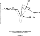
- the red curves (R) are those with only quantum dots (QD).
- the blue curves (B) are those with quantum dots and silver nanoparticles (QD + Ag).
- the purple curves (P) are those with quantum dots and carbon nanotubes (QD + CN).
- the main problem that still needs to be improved is the homogeneity of the samples.
- the vials are stirred vigorously to promote uniform distribution in the particle space.
- the quantum dots tend to rise towards the top of the sample, making the first layer of the cylinder more concentrated in quantum dots.
- the second problem related to the homogeneity of the samples is the sedimentation of the silver nanoparticles and the agglomeration of the carbon nanotubes. Indeed, the silver nanoparticles tend to settle in the bottom of the vial. Again, cutting the samples partially corrects this effect.
- the polishing step does not make it possible to erase all the irregularities of the material. In doing so, from one sample to another there may be differences in the relief of the two faces. These irregularities were visible on the images generated by the beam profiler. We therefore fixed the sample on a removable base having a degree of freedom perpendicular to the movement of the rail. It was then possible to move the sample when the laser passed through an area that seemed less flat.
- the camera software allows the image of the beam profile to be captured in real time.
- the images are recorded using Wink software which captures 35 images per second. This technique is very useful for making a link between what is visible on the screen and the quantitative values of light intensity.
- fluctuations in the laser due to its intermittent instability cannot be corrected. It is therefore difficult to distinguish between a fluctuation of the laser and a nonlinear effect, since the latter are of similar amplitudes.
- it is possible to circumvent this effect by knowing approximately where on the recording the focal point is located.
- the thickness of the blocks cannot be taken into account by the method.
- Table 1 it is noted that the samples do not have exactly the same thickness.
- the charts of Figures 7 and 8 it is the one that generates the most important dips.
- the silver curve in the graph of the Figure 6 also generates a large hollow while this sample is not thicker than the others. The ideal would still be to have similar thicknesses for each of the samples, but the polishing inserts a bias.
- sample series 1 60, 61, 62
- ditto for series 2 63, 64, 65
- the left bearing was the upper one.
- the intensity of the light was always lower from the 0 mm position to the focal point and always stronger from the focal point to the 25 mm position.
- the first step was to introduce quantum dots into a PMMA.
- PMMA rods doped with quantum dots according to the method described here.
- the figure 9 shows the arrangement of several PMMA strips in a cube ( Fig. 9A ) and the same arrangement excited by UV light ( Fig. 9B ).
- the UV excitation shows the presence of photoluminescence which is attributable to the presence of quantum dots in the PMMA.
- the second step was to obtain photoluminescence not from UV light but rather from infrared (IR) light via a two-photon absorption process.
- IR infrared
- Titanium-Sapphire laser with the following specifications: ⁇ b> Table 4: ⁇ /b> Wave length 789 nm Repetition rate 250 kHz Pulse width 82 femtoseconds Minimum average power ⁇ 10 mW
- the lens specifications are as follows: ⁇ b> Table 5 ⁇ /b>: Magnification 5x Focal length 25 mm Numerical aperture 0.1 Entrance Pupil 9 mm
- the photoluminescence is only observable at the focus of the laser, there is no luminescent trail before or after the focus.
- medium minimum power for example ⁇ 10mW
- the beam damages the sample, but photoluminescence is observed.
- Subsequent tests with neutral filters should be done to determine the lower limit of the intensity required for photoluminescence.
- Some damage may be due to thermal effects induced by the short pulse laser.
- the permanent damage etched into the PMMA was measured using a microscope and has a width of 35 microns. Thermal effects and non-linear effects should not be confused. Indeed, the thermal effects accumulate to thus produce a heating of the plastic and produce permanent defects. Non-linear effects or photoluminescence is produced locally and if and only if the beam intensity is sufficient. The area of photoluminescence is localized in one place. This area or volume is defined by the intensity of the laser confinement at the focus of the microscope objective.
- dimension 'b' For a volume screen as shown on the Figure 11 , we can define dimension 'b' by determining the number of pixels in dimension D (depth). Knowing the wavelength of the laser (1), we can then determine the size Wo of the required beam. The number of scanning elements N in the voxel (micro-scanning) is given by the ratio b / 2W 0 which is equal to 2F #. This F # roughly determines the system scan lens requirement .
- the projection system is composed of 3 scanning subsystems.
- An XY scan which would position the focus of the beam for each transverse plane of the image. This type of scanning would probably be done by two galvanometric mirrors.
- the second type of sweep will be at depth (Z). For this axis it will probably be a liquid crystal spatial modulator (SLM) as illustrated on Figure 12 .
- SLM liquid crystal spatial modulator
- the last type of sweep will be used to fill the voxel. This type of scanning could be done by a rotating prism but other types of scanning could be considered. Decoupling the sweep into three parts increases the total system refresh rate.
- the projection system (100) described in figure 12 comprises an IR-laser (110) projecting light onto a first modulator (120) and then onto a mirror (130) deflecting the light towards the spatial liquid crystal modulator (140).
- the spatial modulator (140) On leaving the spatial modulator (140), the light is processed by the YY scanning scanner (150) and its galvanometric mirrors (152-154) before being projected onto the volume screen (160).
- the volume scanning speed is one of the limiting criteria of the system in terms of the number of modulable voxels at a speed of 30 images / second.
- HiResFELIX 3D resolution of the system 500x500x500 voxels (equal to 125 million). From this resolution and the size of the system we can determine the size of the desired voxel , it fixes the size of the rayleigh zone (Z R ) which subsequently imposes on us a size of the beam waist (2 * W 0 ) according to the equations described above.
- the number of microscans is calculated by dividing the area of the voxel by the size of the required beam waist.
- the distance between the scanning system and the display determines the focal length of the scanning lens.
- the f-number (f / #) is defined as the ratio between the focal length (f) and the diameter of a lens (D).
- the size of the beam waist (Wo) and the focal length we can determine the minimum diameter of the scanning lens.
- the “XY scan” value gives the number of transverse points which must be modulated to obtain a plane at 30 images seconds which directly gives the modulation and scan frequency for the system.
- Table 6 ⁇ /b> Minimum average intensity (W / mm 2 ) 1.63. 10 3 W H D Screen size ( display ) (m) 1 1 1 Resolution (number of pixels) 500 500 500 Voxels size (microns) 2000 2000 2000 Number of voxels 125,000,000 Z R : Required Rayleigh area ( ⁇ m) 2000 2W 0 : required ray size ( ⁇ m) 31.69 Number of sweeps / voxels 63.1 * 63.1 Average power (W) 1,291 Scanning Laser distance - Display (m) 0.5 Focal Scan - Lens (?) 0.5 F-number (f / #) 31.55 Min. scan lens diameter (mm) 15.85 XY scan: point / sec number at 30 fps 7.5000.000 Scan XY frequency modulation (MHz) 7.5
- the average laser power calculated in table 6 above is 1.291 W which is quite strong. In order to reduce the power, we can put a volume of 50x50x50 cm which would halve the power required. Another solution is to combine two lasers in order to produce the required intensity. Also, keep in mind that the minimum light intensity specifications required for photoluminescence have not been determined and therefore we are using the minimum power of the test laser (10mW) that produced luminescence in our tests. In addition, these calculations are for a monochromatic system. An RGB color system could preferably be composed of a laminate of successive RGB layers which will reduce by 3 the required for ZR. The power required will also be cut by three in favor of an increase in the Z sweep speed by the SLM. The figure 5 of the article Downing - "A Three-Color, Solid State, Three-Dimensional Display", Science, 1996, p 5279-1185 presents a concept of this type of laminated display.
- Quantum dots can be used to generate nonlinear effects when subjected to high powers. To aspire to practical applications, it is better to trap them in a solid structure rather than leaving them in solution where their toxic contents would be more likely to be exposed to users. As a result, quantum dots were confined in a plastic matrix (such as polymethyl methacrylate). Carbon nanotubes and silver nanoparticles were attached to some of the samples. The objective was to be able to compare the two-photon absorption of the samples using a Z-Scan. This technique measures the intensity of laser light passing through the sample as it travels through the focal point.
Landscapes
- Physics & Mathematics (AREA)
- Chemical & Material Sciences (AREA)
- Engineering & Computer Science (AREA)
- General Physics & Mathematics (AREA)
- Multimedia (AREA)
- Optics & Photonics (AREA)
- Organic Chemistry (AREA)
- Signal Processing (AREA)
- Polymers & Plastics (AREA)
- Health & Medical Sciences (AREA)
- Medicinal Chemistry (AREA)
- Chemical Kinetics & Catalysis (AREA)
- Materials Engineering (AREA)
- Nanotechnology (AREA)
- Biophysics (AREA)
- Computer Vision & Pattern Recognition (AREA)
- Electromagnetism (AREA)
- Crystallography & Structural Chemistry (AREA)
- Life Sciences & Earth Sciences (AREA)
- Investigating, Analyzing Materials By Fluorescence Or Luminescence (AREA)
- Mechanical Optical Scanning Systems (AREA)
- Stereoscopic And Panoramic Photography (AREA)
- Testing, Inspecting, Measuring Of Stereoscopic Televisions And Televisions (AREA)
- Devices For Indicating Variable Information By Combining Individual Elements (AREA)
Description
La présente invention concerne essentiellement le domaine des matériaux nano-composites et du balayage laser en trois dimensions pour applications en projection d'imagerie volumétrique ou en trois dimensions (3D). L'invention est particulièrement adaptée aux domaines de la conception assistée par ordinateur (CAO), du divertissement ou au domaine médical sans toutefois être limitée à ces domaines.The present invention relates essentially to the field of nano-composite materials and three-dimensional laser scanning for applications in volumetric or three-dimensional (3D) imaging projection applications. The invention is particularly suited to the fields of computer-aided design (CAD), entertainment or the medical field without, however, being limited to these fields.
La technologie d'aujourd'hui rend possible la synthèse de matériaux plus complexes et plus adaptés aux besoins expérimentaux et industriels. En ayant une liste précise des caractéristiques souhaitées, le matériau peut être fabriqué pour remplir entièrement la fonction à laquelle il est destiné. L'optique est un des domaines où la science des matériaux vient rendre possible plusieurs avancées expérimentales et théoriques.Today's technology makes possible the synthesis of more complex materials more suited to experimental and industrial needs. By having a precise list of desired characteristics, the material can be manufactured to fully perform the function for which it is intended. Optics is one of the fields where the science of materials makes possible several experimental and theoretical advances.
Les points quantiques sont des nanostructures semi-conductrices. La particularité de ces nanostructures est de toujours réémettre l'énergie absorbée à la même fréquence. Lorsqu'un semiconducteur absorbe de l'énergie, un ou plusieurs électrons se déplacent vers la bande de conduction, laissant un ou plusieurs trous dans la bande de valence. L'électron et le trou restent liés par une force électrique et forment un exciton. Les points quantiques, de par leur nature cristalline, confinent les excitons sur quelques nanomètres dans les trois dimensions comme s'ils étaient pris dans une boîte. Puisque seulement les multiples entiers des longueurs d'ondes sont permis dans la boîte de dimensions fixes, les niveaux d'énergie sont discrétisés. C'est la taille du point quantique qui détermine la longueur d'onde d'émission de celui-ci. Plus un point quantique a un grand rayon, plus courte est sa longueur d'onde d'émission. Par exemple, les points quantiques rouges ont une plus grande taille que les points quantiques bleus. Lorsqu'ils sont excités par une source d'énergie, un de leurs électrons monte vers la bande de conduction pour ensuite se relaxer et retomber dans la bande de valence. Un photon est alors émis par fluorescence.Quantum dots are semiconductor nanostructures. The particularity of these nanostructures is to always re-emit the energy absorbed at the same frequency. When a semiconductor absorbs energy, one or more electrons move towards the conduction band, leaving one or more holes in the valence band. The electron and the hole remain linked by an electric force and form an exciton. Quantum dots, by their crystalline nature, confine excitons to a few nanometers in three dimensions as if they were caught in a box. Since only integer multiples of wavelengths are allowed in the fixed dimension box, the energy levels are discretized. It is the size of the quantum point that determines the emission wavelength of it. The larger a quantum point has a large radius, the shorter is its emission wavelength. For example, red quantum dots are larger in size than blue quantum dots. When excited by an energy source, one of their electrons rises to the conduction band for then relax and fall back into the valence band. A photon is then emitted by fluorescence.
L'absorption linéaire suivie de fluorescence peut être décrite par un objet qui reçoit de l'énergie, principalement électrique ou lumineuse, et se l'approprie. Cet objet, plus énergétique qu'auparavant, se retrouve dans un état excité avec un surplus d'énergie. Dans l'objectif de se relaxer et de retomber à une énergie moindre, l'objet, s'il est fluorescence, peut émettre un photon de longueur d'onde précise. Les points quantiques sont des objets fluorescence qui peuvent absorber de l'énergie lumineuse dans une certaine plage de fréquences et la réémettre à une fréquence propre.Linear absorption followed by fluorescence can be described by an object that receives energy, mainly electric or light, and appropriates it. This object, more energetic than before, is found in an excited state with a surplus of energy. In order to relax and fall back to a lower energy, the object, if it fluoresces, can emit a photon of a specific wavelength. Quantum dots are fluorescence objects that can absorb light energy in a certain frequency range and re-emit it at a natural frequency.
Les points quantiques sont utilisés par plusieurs chercheurs pour diverses applications. Leur synthèse et leurs propriétés sont bien documentées (
Le brevet
Le brevet américain no.
La demande de brevet américain no.
D'autres systèmes de projection volumétriques connus sont décrits dans les demandes de brevets américains nos.
Les systèmes actuels de matrices transparentes dopées avec des nano-émetteurs, tels que des points quantiques ou des nano-cristaux, ont une réponse à l'excitation photonique trop faible pour permettre l'utilisation de ces matrices dans des systèmes de projection volumétrique 3D. Il existe donc un besoin pour un nouveau type de matrice de matériaux nano-composites dont la réponse à l'excitation photonique sera suffisamment puissante pour permettre son utilisation dans ces systèmes de projection volumétriques.Current systems of transparent matrices doped with nano-emitters, such as quantum dots or nano-crystals, have a response to photon excitation too low to allow the use of these matrices in 3D volumetric projection systems. There is therefore a need for a new type of matrix of nano-composite materials whose response to photon excitation will be sufficiently powerful to allow its use in these volumetric projection systems.
L'invention concerne en premier lieu une matrice de projection hybride pour la projection volumétrique d'imagerie en trois dimensions (3D), la matrice comprenant dans un support solide transparent à la lumière une combinaison synergique d'au moins deux types différents de particules à l'intérieur dudit support solide, dont:
- (1) un premier type de particules comprenant des particules nano-émettrices adaptées pour absorber de façon non-linéaire un ou deux photons et émettre une lumière visible ; et
- (1) un second type de particules constitué d'au moins un additif rehaussant l'absorption non-linéaire à un ou deux photons et l'émission de lumière visible par les particules nano-émettrices, permettant ainsi d'intensifier et/ou modifier la lumière émise par les particules nano-émettrices, ledit additif comprenant des nanoparticules d'or, des nanoparticules d'argent, des nanoparticules semiconductrices, de la nanocellulose, des nanotubes de carbone, des matériaux bidimensionnels, du graphène, ou des polymères conducteurs et/ou semi-conducteurs.
- (1) a first type of particles comprising nano-emitting particles adapted to non-linearly absorb one or two photons and emit visible light; and
- (1) a second type of particles consisting of at least one additive enhancing the non-linear absorption at one or two photons and the emission of visible light by the nano-emitting particles, thus making it possible to intensify and / or modify the light emitted by the nano-emitting particles, said additive comprising gold nanoparticles, silver nanoparticles, semiconductor nanoparticles, nanocellulose, carbon nanotubes, two-dimensional materials, graphene, or conductive polymers and / or semiconductors.
L'invention concerne aussi un procédé de fabrication d'une matrice de projection hybride pour la projection volumétrique d'imagerie en trois dimensions (3D), le procédé comprenant les étapes suivantes :
- a) mélanger dans une solution permettant la synthèse d'un support solide transparent à la lumière, une première quantité donnée d'un premier type de particules comprenant des particules nano-émettrices et une seconde quantité donnée d'un second type de particules constitué d'au moins un additif, ledit additif comprenant des nanoparticules d'or, des nanoparticules d'argent, des nanoparticules semiconductrices, de la nanocellulose, des nanotubes de carbone, des matériaux bidimensionnels, du graphène, ou des polymères conducteurs et/ou semi-conducteurs; et
- b) solidifier le mélange obtenu pour obtenir la matrice.
- a) mixing in a solution allowing the synthesis of a solid support transparent to light, a first given quantity of a first type of particles comprising nano-emitting particles and a second given quantity of a second type of particles consisting of 'at least one additive, said additive comprising gold nanoparticles, silver nanoparticles, semiconductor nanoparticles, nanocellulose, carbon nanotubes, two-dimensional materials, graphene, or conductive and / or semi-conductive polymers conductors; and
- b) solidify the mixture obtained to obtain the matrix.
L'invention concerne aussi un système de projection volumétrique d'imagerie en trois dimensions (3D), le système comprenant :
- (1) une source émettrice de photons; et
- (2) la matrice de projection hybride telle que définie ici, la matrice étant située en aval de la source émettrice afin de recevoir les photons depuis la source émettrice, la matrice émettant alors une lumière visible afin de créer une image en trois dimensions. L'invention concerne aussi l'utilisation de la matrice de projection hybride telle que définie ici, pour former une image en trois dimensions.
- (1) a photon emitting source; and
- (2) the hybrid projection matrix as defined here, the matrix being located downstream of the emitting source in order to receive the photons from the emitting source, the matrix then emitting visible light in order to create a three-dimensional image. The invention also relates to the use of the hybrid projection matrix as defined here, to form a three-dimensional image.
L'invention ne se limite pas au nombre de types de particule utilisées dans la matrice, et on pourrait généraliser en ajoutant un troisième, quatrième, cinquième, ... n-ième type de particules pour produire des matrices hybrides tertiaires, quaternaires, etc.The invention is not limited to the number of particle types used in the matrix, and one could generalize by adding a third, fourth, fifth, ... n-th type of particles to produce tertiary, quaternary, etc. hybrid matrices. .
Le but d'introduire le deuxième type de particules ou additifs, est de modifier les propriétés de la matrice contenant le type unique initial de particules afin d'atteindre de meilleures performances de projection volumétrique ou encore générer de nouvelles caractéristiques qui n'existaient pas à une seule particule. L'invention permet aussi de pouvoir mesurer l'absorption non linéaire des points quantiques dans une matrice de plastique et de vérifier l'impact d'un ajout d'additif sur le phénomène.The aim of introducing the second type of particles or additives is to modify the properties of the matrix containing the initial unique type of particles in order to achieve better volumetric projection performance or to generate new characteristics that did not exist at a single particle. The invention also makes it possible to be able to measure the non-linear absorption of quantum dots in a plastic matrix and to verify the impact of an addition of additive on the phenomenon.
Selon un élément préférentiel de l'invention, des points quantiques sont les structures choisies pour produire l'effet non linéaire souhaité dans le matériau optique (matrice). Ils sont retenus de préférence par du plastique afin de pouvoir être utilisés dans un contexte pratique et limiter leurs effets dommageables sur la santé.According to a preferred element of the invention, quantum dots are the structures chosen to produce the desired nonlinear effect in the optical material (matrix). They are preferably retained by plastic in order to be able to be used in a practical context and to limit their damaging effects on health.
De plus, à la différence des systèmes actuels de matrices transparentes dopées avec des nano-émetteurs, tels que des points quantiques ou des nano-cristaux, qui ont une réponse à l'excitation photonique trop faible pour permettre l'utilisation de ces matrices dans des systèmes de projection volumétrique 3D, la réponse à l'excitation photonique par la présente invention est suffisamment puissante pour permettre son utilisation dans ces systèmes de projection volumétriques. De plus, cela permet de diminuer dans le système de projection, la puissance de la source émettrice de photon, telle qu'un laser, tout en obtenant une image visible dans la matrice, permettant ainsi de préserver la matrice plastique en évitant que celle-ci ne fonde sous l'effet du rayon photonique ou laser.Moreover, unlike current systems of transparent matrices doped with nano-emitters, such as quantum dots or nano-crystals, which have a response to photon excitation too low to allow the use of these matrices in 3D volumetric projection systems, the response to photon excitation by the present invention is sufficiently powerful to allow its use in these volumetric projection systems. In addition, this makes it possible to decrease in the projection system, the power of the photon emitting source, such as a laser, while obtaining a visible image in the matrix, thus making it possible to preserve the plastic matrix by preventing it it does not melt under the effect of the photon or laser beam.
Les phénomènes optiques impliqués dans la présente invention portent préférentiellement sur l'absorption à un ou deux photons, plus préférentiellement deux photons, et l'émission de l'énergie par fluorescence. L'absorption à deux photons, suivie de fluorescence, rend possible l'obtention d'une longueur d'onde d'émission visible même lorsque les points quantiques sont excités à l'aide de lumière infrarouge. Cela permet d'exploiter ce phénomène pour fabriquer des écrans à projection volumétrique. De préférence, cette technologie utilise un signal incident invisible pour les yeux humains afin de ne pas altérer l'image présentée. Lorsque le point quantique reçoit le signal, soit deux photons infrarouges, il réémet son énergie en un seul photon visible, créant ainsi une image pouvant être en trois dimensions.The optical phenomena involved in the present invention preferably relate to the absorption with one or two photons, more preferably two photons, and the emission of energy by fluorescence. Two-photon absorption, followed by fluorescence, makes it possible to achieve a visible emission wavelength even when quantum dots are excited using infrared light. This makes it possible to exploit this phenomenon to manufacture volumetric projection screens. Preferably, this technology uses an incident signal invisible to human eyes so as not to alter the image presented. When the quantum dot receives the signal - two infrared photons - it re-emits its energy into a single visible photon, thus creating an image that can be three-dimensional.
La présente invention se démarque préférentiellement dans la mesure où il propose de réunir ces aspects, en plaçant les points quantiques préférentiellement dans un matériau plastique, tel que du PMMA mais non limité à ce matériau, pour caractériser leur absorption non linéaire à l'aide d'un laser Z-Scan. The present invention is preferentially distinguished insofar as it proposes to combine these aspects, by placing the quantum dots preferentially in a plastic material, such as PMMA but not limited to this material, in order to characterize their nonlinear absorption using d 'a Z-Scan laser.
La présente invention ouvre la voie à de nouvelles possibilités de fonctionnalités en plus de viser à rehausser et améliorer tout l'ensemble des propriétés optiques (temps de vie soit la "rapidité" d'émission de lumière, qualité colorimétrique, "quantité d'absorption", etc.) des matériaux qui contiennent uniquement les nano-émetteurs.The present invention opens the way to new possibilities of functionalities in addition to aiming to enhance and improve the whole set of optical properties (lifetime, ie the "speed" of light emission, colorimetric quality, "quantity of absorption. ", etc.) materials which contain only the nano-emitters.
Les caractéristiques de la présente invention qui sont considérées comme nouvelles et inventives seront décrites avec plus de détails dans les revendications présentées ci-après.The features of the present invention which are considered new and inventive will be described in more detail in the claims presented hereinafter.
Les avantages, objectifs et caractéristiques de la présente invention seront plus facilement observables en se référant à la description détaillée suivante qui sera faite à l'aide des figures dans lesquelles :
- La
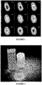
Figure 1 représente la distance du faisceau au détecteur par rapport à la position de l'échantillon. Les distances inscrites sont mesurées approximativement par rapport au point focal du laser. Une présence plus faible de couleur rouge signifie une intensité de lumière moindre, suggérant ainsi de l'absorption. - La
Figure 2 montre des échantillons cylindriques sous de la lumière ultraviolette. La lame circulaire est découpée à partir des cylindres et polie. - La
Figure 3 illustre un montage épuré d'un laser de type Z-Scan avec les paramètres utilisés lors de l'expérimentation. - La
Figure 4 est un graphique présentant l'intensité moyenne de la lumière en fonction de la position des échantillons 60, 61 et 62 à une puissance de 10 mW (OD10). - La
Figure 5 est un graphique présentant l'intensité moyenne de la lumière en fonction de la position des échantillons 60, 61 et 62 à une puissance de 13,5 mW (OD8). - La
Figure 6 est un graphique présentant l'intensité moyenne de la lumière en fonction de la position des échantillons 60, 61 et 62 à une puissance de 20 mW (OD6). - La
Figure 7 est un graphique présentant l'intensité moyenne de la lumière en fonction de la position des échantillons 63, 64 et 65 à une puissance de 20 mW (OD6). - La
Figure 8 est un graphique présentant l'intensité moyenne de la lumière en fonction de la position des échantillons 63, 64 et 65 à une puissance de 24 mW (OD5). - La
Figure 9 montre un arrangement en cube de plusieurs réglettes de PMMA dopée avec des points quantiques, non-éclairé (Figure 9A ) et éclairé par un faisceau de lumière UV (Figure 9B ). - La
Figure 10 illustre un faisceau laser gaussien autour de la zone focale. - La
Figure 11 est un schéma illustrant la géométrie de l'écran de volume. - La
Figure 12 illustre un exemple type de système de balayage laser.
- The
Figure 1 represents the distance of the beam to the detector from the position of the sample. The inscribed distances are measured approximately from the focal point of the laser. A weaker presence of red color means less light intensity, thus suggesting absorption. - The
Figure 2 shows cylindrical samples under ultraviolet light. The circular blade is cut from the cylinders and polished. - The
Figure 3 illustrates a clean set-up of a Z-Scan type laser with the parameters used during the experiment. - The
Figure 4 is a graph showing the average light intensity as a function of the position ofsamples 60, 61 and 62 at a power of 10 mW (OD10). - The
Figure 5 is a graph showing the average light intensity as a function of the position ofsamples 60, 61 and 62 at a power of 13.5 mW (OD8). - The
Figure 6 is a graph showing the average light intensity as a function of the position ofsamples 60, 61 and 62 at a power of 20 mW (OD6). - The
Figure 7 is a graph showing the average light intensity as a function of the position of samples 63, 64 and 65 at a power of 20 mW (OD6). - The
Figure 8 is a graph showing the average light intensity as a function of the position of samples 63, 64 and 65 at a power of 24 mW (OD5). - The
Figure 9 shows a cube arrangement of several PMMA rods doped with quantum dots, unlit (Figure 9A ) and illuminated by a beam of UV light (Figure 9B ). - The
Figure 10 illustrates a Gaussian laser beam around the focal area. - The
Figure 11 is a diagram illustrating the geometry of the volume screen. - The
Figure 12 illustrates a typical example of a laser scanning system.
Selon un premier mode préférentiel de réalisation, l'invention consiste en une matrice de projection hybride pour la projection volumétrique d'imagerie en trois dimensions (3D). La matrice comprend dans un support solide transparent à la lumière une combinaison synergique d'au moins deux types différents de particules :
- (1) un premier type comprenant des particules nano-émettrices adaptées pour absorber de façon non-linéaire un ou deux photons et émettre une lumière visible ; et
- (2) un second type constitué d'au moins un additif rehaussant l'absorption non-linéaire à un ou deux photons et l'émission de lumière visible par les particules nano-émettrices, permettant ainsi d'intensifier et/ou modifier la lumière émise par les particules nano-émettrices.
- (1) a first type comprising nano-emitting particles adapted to non-linearly absorb one or two photons and emit visible light; and
- (2) a second type consisting of at least one additive enhancing the non-linear absorption at one or two photons and the emission of visible light by the nano-emitting particles, thus making it possible to intensify and / or modify the light emitted by the nano-emitting particles.
La matrice est préférentiellement une matrice dans laquelle le support solide transparent à la lumière comprend un support polymérique, tel que par exemple du polyméthacrylate de méthyle (PMMA). On comprend que d'autres matériaux polymères formant des structures transparentes à la lumière pourraient être utilisés dans l'invention.The matrix is preferably a matrix in which the solid support transparent to light comprises a polymeric support, such as, for example, polymethyl methacrylate (PMMA). It is understood that other polymeric materials forming structures transparent to light could be used in the invention.
Préférentiellement, les particules nano-émettrices comprennent des points quantiques, des fils ou tiges quantiques, des puits quantiques, des anneaux quantiques, des nano-cristaux tels que des nano-cristaux cœur/coquille ou des nano-cristaux hétérostructurés, des nano-plaquettes, des molécules fluorescentes, des fluorophores, et/ou des phosphores. Plus préférentiellement, les particules nano-émettrices comprennent des points quantiques.Preferably, the nano-emitting particles comprise quantum dots, quantum wires or rods, quantum wells, quantum rings, nano-crystals such as core / shell nano-crystals or heterostructured nano-crystals, nano-platelets. , fluorescent molecules, fluorophores, and / or phosphors. More preferably, the nano-emitting particles comprise quantum dots.
Les nanoparticules métalliques sont plus préférentiellement des nanoparticules d'argent ou des nanoparticules de carbone.The metal nanoparticles are more preferably silver nanoparticles or carbon nanoparticles.
Préférentiellement, le ou les additifs utilisés dans la présente invention comprennent des nanoparticules d'or, des nanoparticules d'argent, des nanoparticules semiconductrices, de la nano-cellulose, des nanotubes de carbone, des matériaux bidimensionnels, du graphène, ou des polymères conducteurs et/ou semi-conducteurs. Plus préférentiellement, le ou les additifs comprennent des particules métalliques qui sont des nanoparticules d'argent et/ou des nanotubes de carbone.Preferably, the additive (s) used in the present invention comprise gold nanoparticles, silver nanoparticles, semiconductor nanoparticles, nano-cellulose, carbon nanotubes, two-dimensional materials, graphene, or conductive polymers. and / or semiconductors. More preferably, the additive (s) comprise metallic particles which are silver nanoparticles and / or carbon nanotubes.
La matrice est préférentiellement sous la forme d'une lame ayant une épaisseur comprise entre 2 et 5 mm. La lame a préférentiellement une surface polie, avec un fini d'environ 1 µm.The matrix is preferably in the form of a blade having a thickness between 2 and 5 mm. The blade preferably has a polished surface, with a finish of about 1 μm.
Selon un second aspect, l'invention concerne un procédé de fabrication d'une matrice de projection hybride pour la projection volumétrique d'imagerie en trois dimensions (3D), le procédé comprenant les étapes suivantes :
- a) mélanger dans une solution permettant la synthèse d'un support solide transparent à la lumière, une première quantité donnée d'un premier type de particules comprenant des particules nano-émettrices et une seconde quantité donnée d'un second type de particules constitué d'au moins un additif; et
- b) solidifier le mélange obtenu pour obtenir la matrice.
- a) mixing in a solution allowing the synthesis of a solid support transparent to light, a first given quantity of a first type of particles comprising nano-emitting particles and a second given quantity of a second type of particles consisting of at least one additive; and
- b) solidify the mixture obtained to obtain the matrix.
Préférentiellement, la solution permettant la synthèse du support solide transparent à la lumière comprend un monomère qui une fois polymérisé forme un support polymérique transparent à la lumière. Tel que mentionné ci-dessus, la matrice est préférentiellement une matrice dans laquelle le support solide transparent à la lumière comprend un support polymérique, tel que par exemple du polyméthacrylate de méthyle (PMMA). On comprend que d'autres matériaux polymères formant des structures transparentes à la lumière pourraient être utilisés dans l'invention.Preferably, the solution allowing the synthesis of the solid support transparent to light comprises a monomer which, once polymerized, forms a polymeric support transparent to light. As mentioned above, the matrix is preferably a matrix in which the solid support transparent to light comprises a polymeric support, such as, for example, polymethyl methacrylate (PMMA). It is understood that other polymeric materials forming structures transparent to light could be used in the invention.
Selon un mode préférentiel, le procédé de fabrication de la matrice de projection hybride pour la projection volumétrique d'imagerie en trois dimensions (3D) comprend les étapes suivantes :
- a1) mélanger la solution de monomères permettant la synthèse du support polymérique, la première quantité donnée du premier type de particules comprenant les particules nano-émettrices et la seconde quantité donnée du second type de particules comprenant ledit moins un additif ;
- a2) insérer un initiateur de polymérisation dans le mélange ; et
- bl) laisser polymériser le mélange obtenu pour obtenir la matrice.
- a1) mixing the solution of monomers allowing the synthesis of the polymeric support, the first given quantity of the first type of particles comprising the nano-emitting particles and the second given quantity of the second type of particles comprising said at least one additive;
- a2) inserting a polymerization initiator into the mixture; and
- bl) allow the mixture obtained to polymerize to obtain the matrix.
Les matériaux utilisés dans le procédé sont tels que déjà décrits ci-dessus.The materials used in the process are as already described above.
Préférentiellement, pour une matrice à base de points quantiques et de particules métalliques (argent et/ou nanotubes de carbone), le procédé comprend en outre l'étape de préchauffer le mélange à une température d'environ 90°C avant l'insertion de l'initiateur. Le procédé peut comprendre en outre les étapes de verser le mélange dans un moule de forme donnée comme des prismes ou cylindres, et de laisser polymériser le mélange à une température d'environ 75°C pour une durée d'environ 24 h.Preferably, for a matrix based on quantum dots and metallic particles (silver and / or carbon nanotubes), the method further comprises the step of preheating the mixture to a temperature of approximately 90 ° C. before the insertion of initiator. The method may further comprise the steps of pouring the mixture into a mold of given shape such as prisms or cylinders, and of allowing the mixture to polymerize at a temperature of approximately 75 ° C. for a period of approximately 24 h.
Le procédé peut comprendre en outre l'étape de découper la matrice obtenue après polymérisation sous forme de lames parallèles. Le procédé peut comprendre en outre l'étape de sélectionner des lames adjacentes afin d'obtenir des concentrations similaires en nanoparticules dans chacune des lames sélectionnées. Les lames sélectionnées ont préférentiellement une épaisseur entre 2 mm et 5 mm.The method may further comprise the step of cutting the matrix obtained after polymerization in the form of parallel blades. The method may further include the step of selecting adjacent slides to achieve similar concentrations of nanoparticles in each of the selected slides. The blades selected preferably have a thickness between 2 mm and 5 mm.
Le procédé peut comprendre en outre l'étape de polir la lame. La lame polie a préférentiellement un fini d'environ 1 µm.The method may further include the step of polishing the blade. The polished blade preferably has a finish of about 1 μm.
Lors du procédé de fabrication, la matrice comprend préférentiellement une concentration de points quantiques entre 2 µl/ml et 8 µl/ml, et une concentration de nanoparticules d'argent entre 0.01 mg/ml et 0.2 mg/ml. La matrice peut aussi comprend une concentration de points quantiques entre 2 µl/ml et 8 µl/ml, et une concentration de nanotubes de carbone entre 0,0001 mg/ml et 0,01 mg/ml.During the manufacturing process, the matrix preferably comprises a concentration of quantum dots between 2 μl / ml and 8 μl / ml, and a concentration of silver nanoparticles between 0.01 mg / ml and 0.2 mg / ml. The matrix can also include a concentration of quantum dots between 2 μl / ml and 8 μl / ml, and a concentration of carbon nanotubes between 0.0001 mg / ml and 0.01 mg / ml.
Selon un troisième aspect, l'invention consiste en un système de projection volumétrique d'imagerie en trois dimensions (3D). Ce système comprend une source émettrice de photons, tel qu'un laser; et la matrice de projection hybride telle que définie ici. La matrice étant située en aval de la source émettrice afin de recevoir les photons depuis la source émettrice, la matrice émettant alors une lumière visible afin de créer une image en trois dimensions.According to a third aspect, the invention consists of a volumetric projection system for three-dimensional (3D) imaging. This system comprises a source emitting photons, such as a laser; and the hybrid projection matrix as defined here. The matrix being located downstream from the emitting source in order to receive the photons from the emitting source, the matrix then emitting visible light in order to create a three-dimensional image.
Préférentiellement, la source émettrice de photons est un laser qui émet de la lumière, tel que de la lumière infrarouge (IR) invisible, de la lumière UV ou visible. De préférence, on utilise de la lumière IR invisible pour atténuer les interactions avec la lumière émise par la matrice.Preferably, the photon emitting source is a laser which emits light, such as invisible infrared (IR) light, UV or visible light. Preferably, invisible IR light is used to attenuate interactions with the light emitted by the array.
Le système peut comprendre un laser qui produit un balayage X-Y pour positionner un foyer du faisceau pour chaque plan transversal d'une image. Le balayage produit peut être un balayage Z pour positionner un foyer du faisceau pour chaque plan en profondeur de l'image. Le balayage produit peut aussi permettre de remplir un voxel.The system may include a laser that produces an X-Y scan to position a focus of the beam for each transverse plane of an image. The scan produced may be a Z scan to position a focus of the beam for each depth plane of the image. The product sweep can also fill a voxel.
Selon un mode préférentiel de l'invention, le système de projection comprend un laser qui produit un balayage découplé en trois parties permettant d'augmenter une fréquence de rafraîchissement totale du système, le balayage comprenant :
- (1) un premier balayage X-Y pour positionner un foyer du faisceau pour chaque plan transversal d'une image;
- (2) un deuxième balayage Z pour positionner un foyer du faisceau pour chaque plan en profondeur de l'image; et
- (3) un troisième balayage pour compléter une image et remplir un voxel.
- (1) a first XY scan to position a focus of the beam for each transverse plane of an image;
- (2) a second Z scan to position a focus of the beam for each depth plane of the image; and
- (3) a third sweep to complete an image and fill a voxel.
Selon un autre aspect, l'invention consiste en une méthode de projection volumétrique d'imagerie en trois dimensions (3D) qui consiste à projeter des photons sur la matrice de projection hybride telle que définie ici, la matrice émettant alors de la lumière visible pour former une image en trois dimensions.According to another aspect, the invention consists of a volumetric projection method for three-dimensional (3D) imaging which consists in projecting photons onto the hybrid projection matrix as defined here, the matrix then emitting visible light for form a three-dimensional image.
Les éléments de la méthode sont ceux déjà décrits ici.The elements of the method are those already described here.
Absorption à deux photons et fluorescence : Schématisons la situation par un photon incident de fréquence fi qui serait absorbé par un point quantique. Le point quantique réémettrait cette énergie en un photon de fréquence fe où, par conservation d'énergie, fi > fe. La différence d'énergie est perdue en chaleur. Imaginons maintenant que deux photons de fréquence f1 arrivent au même moment sur le point quantique et qu'ils soient tous deux simultanément absorbés. Si 2f1 > f2, où f2 est la fréquence d'émission du point quantique, il se produit de l'absorption à deux photons suivie potentiellement de fluorescence. Pour que le phénomène ait lieu, les photons incidents ne doivent pas obligatoirement être à la même fréquence. Cependant, la somme de leur fréquence respective doit être dans la plage d'absorption du point quantique ou de l'objet étudié. Two-photon absorption and fluorescence : Let us schematize the situation with an incident photon of frequency fi which would be absorbed by a quantum dot. The quantum point would re-emit this energy in a photon of frequency fe where, by conservation of energy, fi> fe. The difference in energy is lost as heat. Now imagine that two photons of frequency f1 arrive at the same time on the quantum dot and that they are both simultaneously absorbed. If 2 f1> f2, where f2 is the emission frequency of the quantum point, two-photon absorption occurs, potentially followed by fluorescence. For the phenomenon to take place, the incident photons do not have to be at the same frequency. However, the sum of their respective frequencies must be within the absorption range of the quantum point or object of interest.
La technique du Z-Scan a pour objectif de mesurer l'indice de réfraction non linéaire et le coefficient d'absorption non linéaire d'un objet. Dans le cadre de la présente invention, seul l'absorption non linéaire a été étudiée qualitativement. Le principe consiste à déplacer l'échantillon de part et d'autre du point focal sur l'axe traversant les sommets des cônes de lumière engendrés par la focalisation du faisceau (voir
En se référant à la
Une nouvelle matrice de projection hybride binaires comprenant au moins deux types de (nano)particules et/ou molécules différentes sera décrit ci-après. Même si l'invention sera décrite en prenant pour exemple une ou plusieurs incarnations préférées, il est important de comprendre que ces incarnations préférées sont utilisées afin d'illustrer l'invention et non afin d'en limiter la portée.A new binary hybrid projection matrix comprising at least two types of (nano) particles and / or different molecules will be described below. Even though the invention will be described by taking as an example one or more preferred embodiments, it is important to understand that these preferred embodiments are used in order to illustrate the invention and not in order to limit its scope.
La première étape de fabrication est le moulage des prismes ou des cylindres de plastique. Lorsque le mélange liquide contenant le méthacrylate de méthyle, les points quantiques, les ajouts métalliques et l'initiateur de polymérisation est fait, l'étape de pré-polymérisation peut être commencée. Par exemple, la température peut être de 90°C. Le montage nécessaire à sa réalisation est essentiellement composé d'une plaque chauffante reposant sur un support universel, d'un bain-marie rempli d'eau placé sur la plaque, d'un thermomètre indiquant la température de l'eau et de deux pinces universelles pour soutenir les échantillons immergés. Suite à l'étape de préchauffage, les blocs sont moulés dans un flacon cylindrique de verre ou dans les moules en aluminium en forme de prisme à base carrée. La technique utilisant les flacons cylindriques est plus facile à réaliser et donne des échantillons plus uniformes. Cependant, la manipulation des échantillons cylindriques est moins commode pour la caractérisation et les fioles, contrairement aux moules d'aluminium ne peuvent pas être utilisées plusieurs fois. Les moules sont par la suite placés dans une étuve à 75°C pour une polymérisation d'environ 24 h (voir annexe 1).The first manufacturing step is the molding of the prisms or plastic cylinders. When the liquid mixture containing the methyl methacrylate, the quantum dots, the metal additions and the polymerization initiator is made, the prepolymerization step can be started. For example, the temperature can be 90 ° C. The assembly necessary for its realization is essentially composed of a heating plate resting on a universal support, a water bath filled with water placed on the plate, a thermometer indicating the temperature of the water and two clamps. universal to support submerged samples. Following the preheating step, the blocks are molded in a cylindrical glass vial or in the aluminum molds in the form of a square-based prism. The technique using the cylindrical vials is easier to perform and gives more uniform samples. However, handling of cylindrical samples is less convenient for characterization and vials, unlike aluminum molds cannot be used multiple times. The molds are then placed in an oven at 75 ° C. for a polymerization of approximately 24 h (see appendix 1).
Les échantillons démoulés sont découpés en lame d'environ 3 mm à l'aide d'une scie à onglet à lame rotative de diamant. Par la suite, les lames sont polies sur une table à polir manuelle jusqu'à l'obtention d'un fini d'environ 1 µm.The demoulded samples are cut into a blade of approximately 3 mm using a miter saw with a rotating diamond blade. The blades are then polished on a manual polishing table until a finish of approximately 1 µm is obtained.
La fabrication de particules nano-émettrices telles que des points quantiques, nano-cristaux, ou autres, est connue de la personne versée dans l'art. Par exemple, on peut se référer aux articles suivants dont le contenu est incorporé ici par référence :
-
Marie-Eve Lecavalier et al. "Water-dispersable colloidal quantum dots for the détection of ionizing radiation", Chem. Commun., 2013,49, 11629-11631 -
C.B. Murray, Synthesis and characterization of nearly monodisperse CdE (E = sulfur, selenium, tellurium) semiconductor nanocrystallites; J. Am. Chem. Soc., 1993, 115 (19), pp 8706-8715 -
Sam Beddar, Luc Beaulieu; "Scintillation Dosimetry", Chapter 19 (ISBN 9781482208993
-
Marie-Eve Lecavalier et al. "Water-dispersable colloidal quantum dots for the detection of ionizing radiation", Chem. Commun., 2013,49, 11629-11631 -
CB Murray, Synthesis and characterization of nearly monodisperse CdE (E = sulfur, selenium, tellurium) semiconductor nanocrystallites; J. Am. Chem. Soc., 1993, 115 (19), pp 8706-8715 -
Sam Beddar, Luc Beaulieu; "Scintillation Dosimetry", Chapter 19 (ISBN 9781482208993
Les additifs particuliers utilisés sont obtenus commercialement :
- Nanotubes de carbone - Fournisseur: Raymor Nanotech <http://raymor.com/nanotech/>, Produit # : RN-02, Description: Nanotube de carbone, >50% C-SWNT;
- Nanoparticules d'argent - Fournisseur: Sigma-Aldrich <http://www.sigmaaldrich.com/canada-francais.html>, Produit # : 576832, Description: Silver nanopowder, <100 nm particule size.
- Carbon nanotubes - Supplier: Raymor Nanotech <http://raymor.com/nanotech/>, Product #: RN-02, Description: Carbon nanotube,> 50% C-SWNT;
- Nanoparticles of silver - Supplier: Sigma-Aldrich <http://www.sigmaaldrich.com/canada-francais.html> Product #: 576832, Description: Silver nanopowder, <100 nm particle size.
Les étapes de fabrication des échantillons peuvent être les suivantes :
- Faire chauffer de l'eau dans un grand cristallisoir à 90°C (avec un agitateur);
- Préparer le mélange liquide de MMA (volatile), ajout métallique, points quantiques et le placer
dans une fiole; - Peser l'initiateur de polymérisation et l'ajouter au mélange liquide;
- Mettre le bouchon de la fiole et agiter jusqu'à ce que le mélange soit limpide;
- Serrer la fiole dans une pince universelle afin de l'immerger dans le cristallisoir à 90°C;
- Démarrer le compte à rebours du temps de préchauffage;
- Lorsque le temps de préchauffage est écoulé, retirer la fiole du cristallisoir;
- Ouvrir le bouchon pour laisser s'échapper le gaz;
- Refermer le bouchon solidement;
- Placer la fiole dans un petit bécher rempli d'eau; et
- Placer le bécher dans une étuve à 75°C pour une journée.
- Heat water in a large crystallizer to 90 ° C (with a stirrer);
- Prepare the liquid mixture of MMA (volatile), metallic addition, quantum dots and place it
in a flask; - Weigh the polymerization initiator and add it to the liquid mixture;
- Put the stopper on the flask and shake until the mixture is clear;
- Tighten the flask in a universal clamp in order to immerse it in the crystallizer at 90 ° C;
- Start the warm-up time countdown;
- When the preheating time has elapsed, remove the vial from the crystallizer;
- Open the cap to let the gas escape;
- Close the cap securely;
- Place the flask in a small beaker filled with water; and
- Place the beaker in an oven at 75 ° C for one day.
La découpe des échantillons peut être réalisée de la façon suivante :
- Retirer les panneaux de la hotte;
- Retirer le bouchon du récipient de la scie;
- Passer la lame de la scie sur un bloc d'affûtage si nécessaire;
- Fixer solidement l'échantillon dans l'étau;
- Ajuster la scie et le chariot à l'aide des déférents degrés de liberté;
- Fixer le chariot sur le rail;
- Ajuster la vitesse de la lame;
- Arroser la lame à l'aide d'une poire tout au long de la coupe;
- Guider manuellement la scie vers l'échantillon et la laisser couper;
- Arrêter la scie lorsque la coupe est terminée et la débrancher; et
- Rincer le récipient de la scie et replacer les panneaux de la hotte.
- Remove the hood panels;
- Remove the cap from the saw container;
- Pass the saw blade over a sharpening block if necessary;
- Securely fix the sample in the vice;
- Adjust the saw and the carriage using the various degrees of freedom;
- Fix the trolley on the rail;
- Adjust the speed of the blade;
- Baste the blade with a pear throughout the cut;
- Manually guide the saw towards the sample and let it cut;
- Stop the saw when the cut is finished and unplug it; and
- Rinse the saw container and replace the hood panels.
Le polissage des échantillons peut être réalisé de la façon suivante :
- Ouvrir les valves d'eau à l'entrée du laboratoire (robinet parallèle au tuyau);
- Déposer un papier abrasif sur la plaque à polir (commencer par un grain 600);
- Démarrer l'eau pour imbiber le papier;
- Placer le socle autour du papier pour le fixer;
- Démarrer la table tournante;
- Ajuster le débit d'eau;
- Déposer l'échantillon sur la table tournante en prenant soin de mettre les lignes de coupe perpendiculaire au rayon de la table;
- Tenir l'échantillon en place jusqu'à ce que les lignes de coupe soient disparues;
- Faire chauffer le porte échantillon sur la plaque chauffante avec un peu de paraffine;
- Lorsque la paraffine est fondue, placer le porte échantillon dans un bain marie et placer l'échantillon face polie à 600 vers le porte échantillon;
- Lorsque la cire a solidifié, insérer le porte échantillon dans le cylindre creux;
- Polir cette face à l'aide des papiers 600, puis 800, puis 1200;
- En suivant la même technique, fixer l'échantillon une nouvelle fois sur le porte échantillon, mais avec l'autre face vers le haut;
- Polir cette face à l'aide des papiers 600, puis 800, puis 1200;
- Retirer l'échantillon du porte échantillon;
- Placer un tapis à polir sur la polisseuse et verser quelques gouttes de solution abrasive de cérium sur le tapis;
- Ajouter un peu d'eau si nécessaire;
- Polir les deux faces; et
- Rincer les papiers sablés, le tapis à polir et laver la polisseuse.
- Open the water valves at the entrance to the laboratory (tap parallel to the pipe);
- Place sandpaper on the polishing plate (start with a 600 grit);
- Start the water to soak the paper;
- Place the base around the paper to secure it;
- Start the turntable;
- Adjust the water flow;
- Place the sample on the turntable, taking care to put the cutting lines perpendicular to the radius of the table;
- Hold the specimen in place until the cut lines are gone;
- Heat the sample holder on the hot plate with a little paraffin;
- When the paraffin is melted, place the sample holder in a water bath and place the sample with the polished face 600 towards the sample holder;
- When the wax has solidified, insert the sample holder into the hollow cylinder;
- Polish this face using papers 600, then 800, then 1200;
- Using the same technique, fix the sample again on the sample holder, but with the other side up;
- Polish this face using papers 600, then 800, then 1200;
- Remove the sample from the sample holder;
- Place a polishing mat on the polisher and pour a few drops of cerium abrasive solution on the mat;
- Add a little water if necessary;
- Polish both sides; and
- Rinse the sand papers, the polishing mat and wash the polisher.
La technique du Z-Scan ne demande pas beaucoup de matériel pour être réalisée. En référence à la
Pour chaque échantillon le temps de préchauffage est de 15 minutes, la masse d'initiateur de polymérisation est de 4 mg et il est à noter que les échantillons contiennent 4 ml de solution et sont complétés par du MMA filtré.For each sample, the preheating time is 15 minutes, the mass of polymerization initiator is 4 mg and it should be noted that the samples contain 4 ml of solution and are completed with filtered MMA.
Une série de graphiques construits à l'aide des Z-Scans est présentée dans les
Les courbes rouges (R) sont celles avec seulement des points quantiques (QD). Les courbes bleues (B) sont celles avec des points quantiques et des nanoparticules d'argent (QD+Ag). Les courbes pourpres (P) sont celles avec des points quantiques et des nanotubes de carbone (QD+CN).
Pour commencer, dans l'étape de fabrication des blocs, le problème principal restant à améliorer est l'homogénéité des échantillons. Après l'étape de préchauffage, les fioles sont agitées vigoureusement pour favoriser une répartition uniforme dans l'espace des particules. Cependant, lors du chauffage dans l'étuve, les points quantiques ont tendance à monter vers le haut de l'échantillon, rendant la première couche du cylindre plus concentrée en points quantiques. Pour pallier cet effet, lors de la coupe des échantillons, la première couche plus concentrée est rejetée. Le second problème en lien avec l'homogénéité des échantillons est la sédimentation des nanoparticules d'argent et l'agglomération des nanotubes de carbone. En effet, les nanoparticules d'argent ont tendance à se déposer dans le fond de la fiole. Encore une fois, la coupe des échantillons permet de corriger en partie cet effet. Pour ce qui est des nanotubes de carbone qui s'agglomèrent, aucune solution n'a été adoptée. Finalement, l'étape du polissage ne permet pas d'effacer toutes les irrégularités du matériau. Ce faisant, d'un échantillon à l'autre il peut y avoir des différences sur le relief des deux faces. Ces irrégularités étaient visibles sur les images générées par le profileur de faisceau. Nous avons donc fixé l'échantillon sur un socle amovible ayant un degré de liberté perpendiculaire au déplacement du rail. Il était alors possible de déplacer l'échantillon lorsque le laser traversait une zone qui semblait moins plane.To begin with, in the block manufacturing step, the main problem that still needs to be improved is the homogeneity of the samples. After the preheating step, the vials are stirred vigorously to promote uniform distribution in the particle space. However, upon heating in the oven, the quantum dots tend to rise towards the top of the sample, making the first layer of the cylinder more concentrated in quantum dots. To overcome this effect, when cutting the samples, the first more concentrated layer is discarded. The second problem related to the homogeneity of the samples is the sedimentation of the silver nanoparticles and the agglomeration of the carbon nanotubes. Indeed, the silver nanoparticles tend to settle in the bottom of the vial. Again, cutting the samples partially corrects this effect. With regard to carbon nanotubes which agglomerate, no solution has been adopted. Finally, the polishing step does not make it possible to erase all the irregularities of the material. In doing so, from one sample to another there may be differences in the relief of the two faces. These irregularities were visible on the images generated by the beam profiler. We therefore fixed the sample on a removable base having a degree of freedom perpendicular to the movement of the rail. It was then possible to move the sample when the laser passed through an area that seemed less flat.
Un second problème a été réglé à l'aide de ce socle amovible. Lorsque les échantillons sont soumis à une trop forte puissance, ils subissent un dommage irréversible au point touché et aux alentours. Or, plusieurs Z-Scan ont été faits sur un même échantillon. Pour pouvoir effectuer le test sur un endroit différent de l'échantillon, il a été déplacé latéralement à l'aide du socle. Il est important de noter qu'aux environs du point focal, le profil du laser occupe approximativement seulement 1/100 de l'échantillon, permettant ainsi cette démarche de correction. Sur la
Le logiciel de la caméra permet de capturer l'image du profil de faisceau en temps réel. Les images sont enregistrées à l'aide du logiciel Wink qui capture 35 images par seconde. Cette technique est très pratique pour faire un lien entre ce qui est visible à l'écran et les valeurs quantitatives d'intensité de lumière. Cependant, les fluctuations du laser dues à son instabilité intermittente ne peuvent pas être corrigées. Il s'avère donc difficile de faire la distinction entre une fluctuation du laser et un effet non linéaire, puisque ceux-ci sont d'amplitudes semblables. Lors de l'interprétation des résultats, il est possible de contourner cet effet en sachant approximativement à quel endroit sur l'enregistrement le point focal se trouve.The camera software allows the image of the beam profile to be captured in real time. The images are recorded using Wink software which captures 35 images per second. This technique is very useful for making a link between what is visible on the screen and the quantitative values of light intensity. However, fluctuations in the laser due to its intermittent instability cannot be corrected. It is therefore difficult to distinguish between a fluctuation of the laser and a nonlinear effect, since the latter are of similar amplitudes. When interpreting the results, it is possible to circumvent this effect by knowing approximately where on the recording the focal point is located.
La sélection de la zone d'intérêt sur le logiciel ImageJ pourrait entraîner une cause de biais puisque la section n'est pas identique pour chaque échantillon. Une zone d'intérêt de taille identique ne serait pas fonctionnelle puisque d'une mesure à l'autre, le profil du faisceau laser est changeant. Cependant j'ai procédé à un contrôle de vérification en comparant plusieurs zones pour me rendre compte du peu d'impact occasionné par la sélection pour autant qu'elle soit raisonnable.The selection of the area of interest on the ImageJ software could lead to a cause of bias since the section is not the same for each sample. An area of interest of identical size would not be functional since from one measurement to another, the profile of the laser beam changes. However, I carried out a verification check by comparing several areas to realize the little impact caused by the selection as long as it is reasonable.
Lors de l'interprétation des résultats, il est difficile de distinguer la différence entre un creux dû à un effet non linéaire et une altération du matériau. En effet, en regardant les graphiques des
Finalement, l'épaisseur des blocs ne peut pas être prise en compte par la méthode. Or, en se référant au Tableau 1, on remarque que les échantillons n'ont pas exactement la même épaisseur. Un échantillon en particulier, celui contenant les nanoparticules d'argent de la série 2, a environ 1 mm de plus d'épaisseur. Dans les graphiques des
Comme on peut voir au Tableau 1, la série d'échantillons 1 (60, 61, 62) possède la même concentration de points quantiques dans chacun de ses éléments. Idem pour la série 2 (63, 64, 65), mis à part le fait qu'elle est uniformément plus concentrée en points quantiques. Il a été choisi de procéder ainsi pour pouvoir comparer les échantillons sans métal et ceux qui en contiennent.As can be seen in Table 1, sample series 1 (60, 61, 62) has the same concentration of quantum dots in each of its elements. Ditto for series 2 (63, 64, 65), except for the fact that it is uniformly more concentrated in quantum dots. He was chose to proceed in this way in order to be able to compare the samples without metal and those containing it.
Les graphiques présentés sont une représentation visuelle du phénomène d'absorption non linéaire. Il est intéressant de remarquer que peu importe la valeur de puissance, les échantillons contenant les nanotubes de carbone génèrent des courbes très semblables à celles des points quantiques seuls, suggérant ainsi l'absence d'effet supplémentaire. Les nanotubes de carbone utilisés dans les échantillons n'étaient pas complètement métalliques et il est probable que l'agrégation des particules ait bloqué un effet quelconque. Pour synthétiser les cinq graphiques des
Aux graphiques des
Finalement, en se fiant au Tableau 3 qui présente le seuil de fluorescence des échantillons mesuré à l'œil nu, on conclut rapidement que pour une concentration de points quantiques donnée, le seuil de fluorescence est le même.Finally, by relying on Table 3 which presents the fluorescence threshold of the samples measured with the naked eye, it is quickly concluded that for a given concentration of quantum dots, the fluorescence threshold is the same.
À la lumière de toutes ces constations, il est possible de suggérer que la présence de nanoparticules d'argent a un effet, quel qu'il soit, sur les propriétés du matériau. Cependant, puisque les seuils de fluorescence sont semblables pour chacun des échantillons et que si l'effet d'absorption non linéaire était réellement amplifié par les nanoparticules d'argent, il le serait également à basse puissance pourvu qu'il y ait absorption à deux photons, il est tendance de penser que les creux plus profonds des graphiques des
Pour améliorer la méthode, il serait avantageux de pouvoir mesurer les fluctuations du laser à l'aide d'une déviation partielle du faisceau vers une photodiode permettant de choisir adéquatement les périodes de prises de mesures. De plus, il serait intéressant de développer une manière de synchroniser le rail de déplacement avec le logiciel de mesure pour que toutes les courbes aient exactement le même déplacement en fonction du temps, standardisant ainsi l'axe des abscisses.To improve the method, it would be advantageous to be able to measure the fluctuations of the laser using a partial deflection of the beam towards a photodiode making it possible to suitably choose the periods for taking measurements. In addition, it would be interesting to develop a way to synchronize the displacement rail with the measurement software so that all the curves have exactly the same displacement as a function of time, thus standardizing the abscissa axis.
Même si l'effet important créé par les échantillons contenant les nanoparticules d'argent visible dans les graphiques 3, 4 et 5 n'est pas une augmentation de l'absorption non linéaire, il semble qu'un effet soit bel et bien présent. D'autres mesures et la fabrication de nouvelles séries d'échantillons pourraient aider à mettre en lumière la nature de ce phénomène.Even if the important effect created by the samples containing the silver nanoparticles visible in
Nous décrivons ci-après des expériences réalisées pour obtenir une photoluminescence à deux photons dans des matrices de PMMA (plexiglas) dopé par des points quantiques. Nous établissons aussi des requis fonctionnelles d'un système de projection et les étapes requises pour la mise œuvre du système de projection volumétrique.We describe below experiments carried out to obtain a two-photon photoluminescence in PMMA (plexiglass) matrices doped with quantum dots. We also establish functional requirements of a projection system and the steps required for the implementation of the volumetric projection system.
La première étape consistait à introduire dans un PMMA des points quantiques. Nous avons fabriqué ainsi des réglettes de PMMA dopé avec des points quantiques selon la méthode décrite ici. La
La seconde étape consistait à obtenir de la photoluminescence non pas à partir de la lumière UV mais plutôt avec de la lumière infrarouge (IR) via un processus d'absorption à deux photons. Tout d'abord, les résultats avec le premier laser YAG (1064 nm) en continue furent décevant. En effet, le PMMA se mettait à fondre à une certaine intensité sans pour autant produire de la photoluminescence. En utilisant un laser YAG pulsé (5-7 ns) à une fréquence de 10 Hz, nous avons pu observer de la photoluminescence mais encore ici le PMMA était endommagé.The second step was to obtain photoluminescence not from UV light but rather from infrared (IR) light via a two-photon absorption process. First of all, the results with the first continuous YAG laser (1064 nm) were disappointing. Indeed, the PMMA began to melt at a certain intensity without producing photoluminescence. Using a pulsed YAG laser (5-7 ns) at a frequency of 10 Hz, we were able to observe photoluminescence but here again the PMMA was damaged.
Nous avons utilisé dans un troisième temps un laser Titane-Saphir ayant les spécifications suivantes:
Nous avons de plus utilisé un objectif de microscope pour focaliser la lumière. Les spécifications de l'objectif sont les suivantes:
Dans tous les tests suivants, la photoluminescence n'est observable qu'au foyer du laser, il n'y a pas de traîné luminescente avant ou après le foyer. À puissance minimale moyenne, par exemple < 10mW, en mode statique (aucun balayage), le faisceau endommage l'échantillon, mais on observe de la photoluminescence. On ne peut pas trouver d'intensité minimale requise (seuil) en mode statique avec ces tests puisque qu'on observe déjà une photoluminescence. Des tests subséquents avec des filtres neutres devront être faits pour déterminer la limite inférieure de l'intensité requise pour la photoluminescence.In all of the following tests, the photoluminescence is only observable at the focus of the laser, there is no luminescent trail before or after the focus. At medium minimum power, for example <10mW, in static mode (no scanning), the beam damages the sample, but photoluminescence is observed. We cannot find a minimum required intensity (threshold) in static mode with these tests since we are already observing photoluminescence. Subsequent tests with neutral filters should be done to determine the lower limit of the intensity required for photoluminescence.
Toujours à puissance minimale, par exemple < 10mW, mais en déplaçant le faisceau à une vitesse de 1 mm/s, on observe de la photoluminescence et il n'y a aucun dommage permanent d'observable dans le PMMA.Always at minimum power, for example <10mW, but by moving the beam at a speed of 1 mm / s, photoluminescence is observed and there is no permanent damage observable in the PMMA.
En se déplaçant toujours à 1 mm/s, il est possible d'augmenter la puissance jusqu'à environ 35 mW de puissance moyenne avant de voir des dommages permanent. Il est possible d'augmenter la puissance > 50 mW, et n'observer aucun dommage si on augmente la vitesse de balayage plus grande que 1 mm/s.By always moving at 1mm / s, it is possible to increase the power to around 35mW of average power before seeing permanent damage. It is possible to increase the power> 50 mW, and not observe any damage if the scanning speed is increased greater than 1 mm / s.
Certains dommages peuvent être dus aux effets thermiques induits par le laser à impulsions brèves. Les dommages permanents gravés dans le PMMA ont été mesurés à l'aide d'un microscope et ont une largeur de 35 microns. Il ne faut pas confondre effets thermique et effets non-linéaires. En effet, les effets thermiques s'accumulent pour ainsi produire un échauffement du plastique et produire des défauts permanents. Les effets non-linéaires ou la photoluminescence est produite localement et si et seulement si l'intensité du faisceau est suffisante. La zone de photoluminescence est localisée à un endroit. Cette zone ou volume est défini par l'intensité du confinement laser au foyer de l'objectif de microscope.Some damage may be due to thermal effects induced by the short pulse laser. The permanent damage etched into the PMMA was measured using a microscope and has a width of 35 microns. Thermal effects and non-linear effects should not be confused. Indeed, the thermal effects accumulate to thus produce a heating of the plastic and produce permanent defects. Non-linear effects or photoluminescence is produced locally and if and only if the beam intensity is sufficient. The area of photoluminescence is localized in one place. This area or volume is defined by the intensity of the laser confinement at the focus of the microscope objective.
Dans un premier temps, nous faisons l'hypothèse que le volume de la zone fluorescente est confiné autour de la zone focale ou le faisceau laser est confiné. La distance axiale est limitée à la zone de Rayleigh (b) et l'étendu transverse est limité par le 'waist' (W0) du faisceau tel qu'illustrer à la ![]()
![]()
![]()
![]()
![]()
![]()
Nous constatons toutefois ce n'est pas le cas. Plusieurs éléments peuvent expliquer cette situation. Il est possible que la matrice de PMMA diffuse la lumière, ce qui augmente la zone que nous percevons en augmentant ainsi la taille artificiellement de la zone fluorescente. Il est également possible que la lumière fluorescente émise par la zone excitée par le laser excite à son tour des points quantiques (excitation à 1 photon) qui fluorescent en augmentant ainsi la taille de la zone fluorescente visible. Une combinaison des deux facteurs mentionnés pourrait aussi expliquer la situation. Quoiqu'il en soit, cette situation commande d'examiner dans l'avenir le couplage autour de la zone excitée par le laser (cross talk entre les voxels). However, we find that is not the case. Several elements can explain this situation. It is possible that the PMMA matrix will scatter light, which increases the area we perceive thereby artificially increasing the size of the fluorescent area. It is also possible that the fluorescent light emitted from the area excited by the laser in turn excites quantum dots (1-photon excitation) which fluoresce thereby increasing the size of the visible fluorescent area. A combination of the two factors mentioned could also explain the situation. Be that as it may, this situation requires examining in the future the coupling around the zone excited by the laser (cross talk between the voxels).
En se basant sur l'hypothèse que le volume de photoluminescence est confiné à la zone focale, nous pouvons donc établir que pour obtenir un volume de photoluminescence cubique, il faudra balayer latéralement le voxel sur une dimension 'b'. Ceci a pour conséquence qu'il sera préférentiellement nécessaire d'avoir un mécanisme de balayage du faisceau en XY afin de « remplir » le voxel. Le balayage pourrait se faire en 'raster scan' telle qu'illustré à la
Pour un écran de volume tel qu'illustrée sur la
En se basant sur des systèmes similaires, le système de projection est composé de 3 sous-systèmes de balayage. Un balayage X-Y qui viendrait positionner le foyer du faisceau pour chaque plan transversal de l'image. Ce type de balayage serait fait probablement par deux miroirs galvanométriques. Le deuxième type de balayage se fera en profondeur (Z). Pour cet axe il s'agira probablement d'un modulateur spatial à cristaux liquides (SLM) tel qu'illustré à la
La vitesse de balayage du volume est un des critères limitant du système en termes de nombre de voxels modulables à une vitesse de 30 images/secondes. En se basant sur une valeur d'environ 150 millions de voxels atteignable dans d'autre système de balayage 3D (HiResFELIX), on peut poser comme résolution 3D du système de 500x500x500 voxels (égale à 125 millions). De cette résolution et de la taille du système on peut déterminer la taille du voxel désiré, celui-ci fixe la taille de la zone de rayleigh (ZR) qui par la suite nous impose une taille du beam waist (2*W0) selon les équations décrites ci-haut. Le nombre de micro-balayage est calculé en divisant l'aire du voxel par la taille du beam waist requis. Finalement, en utilisant les valeurs d'intensité (Watts/mm2) calculées pour nos tests avec le laser Ti-Saphire et l'aire du nouveau beam waist requis pour l'affichage choisi, nous pouvons déterminer la puissance moyenne requise du laser pour cette nouvelle dimension du faisceau laser requise. ![]()
![]()
![]()
![]()
La valeur Imoy=1.63e+3 Watt/mm2, nécessaire à la photoluminescence, a été calculée à partir des données prise en laboratoire (Pmoy = 0,01 W et 2W0=2,79 microns). Cette valeur n'est pas nécessairement le minimum et d'autres valeurs pourraient être atteintes.The value Imoy = 1.63e +3 Watt / mm 2 , necessary for photoluminescence, was calculated from data taken in the laboratory (P avg = 0.01 W and 2W 0 = 2.79 microns). This value is not necessarily the minimum and other values could be reached.
La distance entre le système de balayage et l'affichage détermine la longueur focale de la lentille de balayage. Le f-number (f/#) est défini comme le ratio entre la longueur focale (f) et le diamètre d'une lentille (D). Wo est proportionnelle au f# selon l'équation suivante. ![]()
![]()
Avec cette équation, la taille du beam waist (Wo) et la longueur focale, nous pouvons déterminer le diamètre minimal de la lentille de balayage. Finalement, puisque les balayages en XY et Z sont découplés, la valeur « balayage XY » donne le nombre de point transversaux qui doivent être modulés pour obtenir un plan à 30 images secondes ce qui donne directement la fréquence de modulation et balayage pour le système.With this equation, the size of the beam waist (Wo) and the focal length, we can determine the minimum diameter of the scanning lens. Finally, since the XY and Z scans are decoupled, the “XY scan” value gives the number of transverse points which must be modulated to obtain a plane at 30 images seconds which directly gives the modulation and scan frequency for the system.
Les tableaux 6 et 7 suivants résument les paramètres calculés d'un éventuel système de projection 3D.
La puissance moyenne laser calculée dans le tableau 6 précédent est de 1.291 W ce qui est assez fort. Afin de réduire la puissance, on peut poser un volume de 50x50x50 cm ce qui diminuerait de moitié la puissance requise. Une autre solution est de combiner deux lasers afin de produire l'intensité requise. Aussi, il faut garder en tête que les spécifications d'intensité lumineuse minimale requises pour la photoluminescence n'ont pas été déterminées et nous utilisons donc la puissance minimale du laser de test (10mW) qui a produit de la luminescence dans nos tests. De plus, ces calculs sont pour un système monochromatique. Un système couleur RGB pourrait être préférentiellement composé d'un laminé de couches RGB successives ce qui diminuera par 3 le requis pour ZR. La puissance requise sera aussi coupée par trois au profit d'une augmentation de la vitesse de balayage en Z par le SLM. La
Les points quantiques peuvent être utilisés pour générer des effets non linéaires lorsqu'ils sont soumis à de fortes puissances. Pour aspirer à des applications pratiques, il est préférable de les emprisonner dans une structure solide plutôt que de les laisser en solution où leur contenu toxique aurait plus de chance d'être exposé aux utilisateurs. Conséquemment, des points quantiques ont été confinés dans une matrice de plastique (tel que du polyméthacrylate de méthyle). Des nanotubes de carbone et des nanoparticules d'argent ont été joints à certains des échantillons. L'objectif était de pouvoir comparer l'absorption à deux photons des échantillons à l'aide d'un Z-Scan. Cette technique mesure l'intensité de lumière du laser qui traverse l'échantillon lors de son déplacement à travers le point focal.Quantum dots can be used to generate nonlinear effects when subjected to high powers. To aspire to practical applications, it is better to trap them in a solid structure rather than leaving them in solution where their toxic contents would be more likely to be exposed to users. As a result, quantum dots were confined in a plastic matrix (such as polymethyl methacrylate). Carbon nanotubes and silver nanoparticles were attached to some of the samples. The objective was to be able to compare the two-photon absorption of the samples using a Z-Scan. This technique measures the intensity of laser light passing through the sample as it travels through the focal point.
Lorsque les points quantiques ont été placés dans le faisceau focalisé du laser, il était possible de voir de la fluorescence orange à l'oeil nu. Suite à la prise de mesures, nous avons observé que la présence de nanotubes de carbone ne semblait pas affecter l'absorption non linéaire. Nous avons cependant observé que la présence de nanoparticules d'argent pourrait augmenter cet effet jusqu'à quatre fois. Toutefois, nous avons également constaté que le seuil de dommage du matériau était d'approximativement 30 mW, alors que le seuil de fluorescence était de 2 mW. Ces deux valeurs étant relativement proches, l'absorption non linéaire et le dommage du matériau sont difficilement distinguables.When the quantum dots were placed in the focused laser beam, it was possible to see orange fluorescence with the naked eye. After taking measurements, we observed that the presence of carbon nanotubes did not seem to affect the nonlinear absorption. However, we observed that the presence of silver nanoparticles could increase this effect up to four times. However, we also found that the material damage threshold was approximately 30 mW, while the fluorescence threshold was 2 mW. These two values being relatively close, the nonlinear absorption and the damage of the material are difficult to distinguish.
Bien qu'elle ait été décrite à l'aide d'une ou plusieurs incarnations préférées, il faut bien comprendre que la présente invention peut être utilisée, employée et/ou incarnée dans une multitude d'autres formes. Ainsi, les revendications qui suivent doivent être interprétées de façon à inclure ces différentes formes tout en restant à l'extérieur des limites fixées par l'art antérieur.Although it has been described using one or more preferred embodiments, it should be understood that the present invention can be used, employed and / or embodied in a multitude of other forms. Thus, the claims which follow must be interpreted so as to include these different forms while remaining outside the limits fixed by the prior art.
Claims (15)
- A hybrid projection matrix comprising a solid support transparent to light and a synergistic combination of at least two different types of particles inside of the solid support transparent to light, wherein:(1) a first type of particles comprising nano-emitting particles adapted to nonlinearly absorb one or two photons and emit visible light; and(2) a second type of particles comprising at least one additive enhancing the nonlinear absorption to one or two photons and the emission of light visible by the nano-emitting particles, thus making it possible to intensify and/or modify the light emitted by the nano-emitting particles, the said additive comprising nanoparticles of gold, nanoparticles of silver, semiconductor nanoparticles, nanocellulose, carbon nanotubes, two-dimensional materials, graphene, or conductive and/or semi-conductive polymers.
- The matrix according to claim 1, wherein the light-transparent solid support comprises a polymeric support, the polymeric support comprising polymethylmethacrylate.
- The matrix according to any one of claims 1 or 2, wherein the nano-emitting particles comprise quantum dots, quantum wires or rods, quantum wells, quantum rings, nano-crystals, nanoplates, fluorescent molecules , fluorophores, and/or phosphors.
- A process for making a hybrid projection matrix, the process comprising the following steps:a) mixing in a solution allowing the synthesis of a solid support transparent to light, a first given amount of a first type of particles comprising nano-emitting particles and a second given quantity of a second type of particles consisting of at least one additive, the additive comprising nanoparticles of gold, nanoparticles of silver, semiconductor nanoparticles, nanocellulose, carbon nanotubes, two-dimensional materials, graphene, or conductive and/or semi-conductive polymers; andb) solidifying the resulting mixture to obtain the matrix.
- The process according to claim 4, wherein the solution for synthesizing the solid light-transparent support comprises a monomer which, once polymerized, forms a polymeric support transparent to light.
- The process according to claim 5, comprising the following steps:a1) mixing the monomer solution allowing the synthesis of the polymer support, the first given quantity of the first type of particles comprising the nano-emitting particles and the second given quantity of the second type of particles comprising at least one additive;a2) inserting a polymerization initiator into the mixture; andb1) allowing the resulting mixture to polymerize to obtain the matrix.
- The process according to claim 5 or 6, wherein the polymeric support comprises polymethylmethacrylate.
- The process according to any one of claims 5 to 7, wherein the nano-emitting particles comprise quantum dots, quantum wires or rods, quantum wells, quantum rings, nano-crystals, nanoplates, fluorescent molecules , fluorophores, and/or phosphors.
- A three dimensional (3D) imaging volumetric projection system, the system comprising:(1) a photon emitting source; and(2) the hybrid projection matrix as defined in any one of claims 1 to 3, the matrix being located downstream of the emitting source in order to receive the photons from the emitting source, the matrix then emitting visible light in order to create a three-dimensional image.
- The system according to claim 9, wherein the laser produces a scan to fill a voxel.
- The system according to claim 10, wherein the laser produces a decoupled three-part scan to increase a total refresh rate of the system, said scanning comprising:(1) a first X-Y scan for positioning a focal point of the beam for each transverse plane of an image;(2) a second Z scan for positioning a focal point of the beam for each depth plane of the image; and(3) a third scan to complete an image and fill a voxel.
- A method for three-dimensional (3D) imaging volumetric projection, the method consisting in projecting photons onto the hybrid projection matrix as defined in any one of claims 1 to 3, the matrix then emitting visible light to form a three-dimensional image.
- The method according to claim 12, wherein the laser produces a decoupled scan in three portions to increase a total refresh rate of the system, the scanning comprising:(1) a first X-Y scan for positioning a focal point of the beam for each transverse plane of an image;(2) a second Z scan for positioning a focal point of the beam for each depth plane of the image; and(3) a third scan to complete an image and fill a voxel.
- The matrix according to any one of claims 1 to 3, wherein the matrix is in the form of a sheet having a thickness between 2 to 5 mm.
- The matrix according to claim 14, wherein the polished sheet has a polished surface.
Applications Claiming Priority (2)
| Application Number | Priority Date | Filing Date | Title |
|---|---|---|---|
| CA2889103A CA2889103A1 (en) | 2015-04-21 | 2015-04-21 | Hybrid nanocomposite materials and their application in a volumetric projection system |
| PCT/CA2016/050466 WO2016168936A1 (en) | 2015-04-21 | 2016-04-21 | Hybrid nanocomposite materials, laser scanning system and use thereof in volumetric image projection |
Publications (3)
| Publication Number | Publication Date |
|---|---|
| EP3286912A1 EP3286912A1 (en) | 2018-02-28 |
| EP3286912A4 EP3286912A4 (en) | 2018-08-08 |
| EP3286912B1 true EP3286912B1 (en) | 2021-09-08 |
Family
ID=57139692
Family Applications (1)
| Application Number | Title | Priority Date | Filing Date |
|---|---|---|---|
| EP16782433.3A Active EP3286912B1 (en) | 2015-04-21 | 2016-04-21 | Hybrid nanocomposite materials, laser scanning system and use thereof in volumetric image projection |
Country Status (9)
| Country | Link |
|---|---|
| US (1) | US10459330B2 (en) |
| EP (1) | EP3286912B1 (en) |
| JP (1) | JP2018520533A (en) |
| KR (1) | KR20180030774A (en) |
| CN (1) | CN107836113B (en) |
| CA (2) | CA2889103A1 (en) |
| HK (1) | HK1252268A1 (en) |
| RU (1) | RU2716863C2 (en) |
| WO (1) | WO2016168936A1 (en) |
Families Citing this family (3)
| Publication number | Priority date | Publication date | Assignee | Title |
|---|---|---|---|---|
| JP2022127856A (en) * | 2021-02-22 | 2022-09-01 | シャープ福山レーザー株式会社 | projector |
| CN115118939B (en) * | 2021-03-17 | 2024-02-02 | 成都理想境界科技有限公司 | Image brightness homogenizing method, computer readable storage medium, electronic device and laser projection image processing device |
| CN115933214B (en) * | 2023-03-09 | 2023-05-30 | 成都理工大学工程技术学院 | Photo-induced three-dimensional imaging device and manufacturing method thereof |
Family Cites Families (27)
| Publication number | Priority date | Publication date | Assignee | Title |
|---|---|---|---|---|
| US4767494A (en) * | 1986-07-04 | 1988-08-30 | Nippon Telegraph & Telephone Corporation | Preparation process of compound semiconductor |
| JP3243303B2 (en) * | 1991-10-28 | 2002-01-07 | ゼロックス・コーポレーション | Quantum confined semiconductor light emitting device and method of manufacturing the same |
| US5472759A (en) * | 1993-12-16 | 1995-12-05 | Martin Marietta Corporation | Optical volume memory |
| DE19506291A1 (en) * | 1995-02-23 | 1996-08-29 | Hoesch Metall & Kunststoffwerk | Simplified prodn. of reinforced plastic baths esp. from acrylic] sheet |
| FR2764892B1 (en) * | 1997-06-23 | 2000-03-03 | Rhodia Chimie Sa | PROCESS FOR THE SYNTHESIS OF BLOCK POLYMERS |
| US6897999B1 (en) * | 1998-11-25 | 2005-05-24 | The Research Foundation Of The University Of Central Florida | Optically written display |
| US6560382B1 (en) * | 1999-02-18 | 2003-05-06 | The United States Of America As Represented By The Secretary Of The Navy | System for alternately directing optical energy through multiple optical modulation channels |
| JP2003029201A (en) * | 2001-07-11 | 2003-01-29 | Canon Inc | Picture projecting device and picture correcting method |
| JP2003287711A (en) * | 2002-03-27 | 2003-10-10 | National Institute Of Advanced Industrial & Technology | Method and apparatus for displaying three-dimensional image |
| US20040227694A1 (en) * | 2003-05-14 | 2004-11-18 | Xiao-Dong Sun | System and method for a three-dimensional color image display utilizing laser induced fluorescence of nanopartcles and organometallic molecules in a transparent medium |
| JP5594718B2 (en) | 2006-04-25 | 2014-09-24 | ザ ボード オブ リージェンツ オブ ザ ユニヴァーシティ オブ オクラホマ | Optical surface display and method for rendering three-dimensional images |
| TWI345110B (en) * | 2006-09-05 | 2011-07-11 | Ind Tech Res Inst | Color backlight device and liquid crystal display thereof |
| JP2008266628A (en) * | 2007-03-27 | 2008-11-06 | Dainippon Printing Co Ltd | Phosphor particle dispersion, and three-dimentional display device and two-dimentional display device using the same |
| US8785906B2 (en) * | 2007-05-30 | 2014-07-22 | Eastman Kodak Company | Lamp with controllable spectrum |
| RU2470037C2 (en) * | 2007-08-31 | 2012-12-20 | Эксонмобил Кемикэл Пейтентс Инк. | Method of reducing deposits in polymerisation vessels |
| CN104864818B (en) * | 2008-07-24 | 2018-09-11 | 麻省理工学院 | The system and method being imaged for using absorption |
| US8664625B2 (en) * | 2009-07-16 | 2014-03-04 | Disney Enterprises, Inc. | Invisible three-dimensional image and methods for making, using and visibility of same |
| US8506559B2 (en) * | 2009-11-16 | 2013-08-13 | Alcon Lensx, Inc. | Variable stage optical system for ophthalmic surgical laser |
| WO2011081037A1 (en) | 2009-12-28 | 2011-07-07 | 独立行政法人産業技術総合研究所 | Fluorescent particle, with semiconductor nanoparticles dispersed therein, fabricated by the sol-gel process |
| CN103081107B (en) * | 2010-03-09 | 2017-02-08 | 得克萨斯州大学系统董事会 | Porous and non-porous nanostructures |
| US8692446B2 (en) * | 2011-03-17 | 2014-04-08 | 3M Innovative Properties Company | OLED light extraction films having nanoparticles and periodic structures |
| RU2465299C1 (en) * | 2011-06-22 | 2012-10-27 | Учреждение Российской Академии Наук Институт Общей И Неорганической Химии Им. Н.С. Курнакова Ран (Ионх Ран) | Method of producing colloidal solutions of luminescent nanoplates of rare-earth oxides |
| CN104302572B (en) * | 2012-03-19 | 2018-02-02 | 奈科斯多特股份公司 | Include the luminaire and its manufacture method of the flat colloidal semiconductor nanocrystal of anisotropy |
| US9557573B2 (en) * | 2012-05-09 | 2017-01-31 | Merck Patent Gmbh | Three dimensional display system |
| US9335027B2 (en) | 2013-01-02 | 2016-05-10 | Massachusetts Institute Of Technology | Methods and apparatus for transparent display using scattering nanoparticles |
| EP2929522B1 (en) | 2013-01-02 | 2018-04-25 | Massachusetts Institute Of Technology | Methods and apparatus for transparent display using scattering nanoparticles |
| CN104507194B (en) * | 2014-12-10 | 2017-02-22 | 上海洞舟实业有限公司 | Fabrication method of third-dimensional (3D) electroluminescent device |
-
2015
- 2015-04-21 CA CA2889103A patent/CA2889103A1/en not_active Abandoned
-
2016
- 2016-04-21 US US15/568,391 patent/US10459330B2/en active Active
- 2016-04-21 KR KR1020177033723A patent/KR20180030774A/en not_active Application Discontinuation
- 2016-04-21 WO PCT/CA2016/050466 patent/WO2016168936A1/en active Application Filing
- 2016-04-21 EP EP16782433.3A patent/EP3286912B1/en active Active
- 2016-04-21 CA CA2983656A patent/CA2983656C/en active Active
- 2016-04-21 JP JP2017555407A patent/JP2018520533A/en active Pending
- 2016-04-21 CN CN201680031289.0A patent/CN107836113B/en active Active
- 2016-04-21 RU RU2017139569A patent/RU2716863C2/en active
-
2018
- 2018-09-08 HK HK18111580.3A patent/HK1252268A1/en unknown
Also Published As
| Publication number | Publication date |
|---|---|
| EP3286912A1 (en) | 2018-02-28 |
| CA2889103A1 (en) | 2016-10-21 |
| CN107836113B (en) | 2021-03-30 |
| RU2017139569A (en) | 2019-05-21 |
| WO2016168936A1 (en) | 2016-10-27 |
| KR20180030774A (en) | 2018-03-26 |
| CA2983656C (en) | 2023-10-03 |
| CN107836113A (en) | 2018-03-23 |
| EP3286912A4 (en) | 2018-08-08 |
| US10459330B2 (en) | 2019-10-29 |
| RU2017139569A3 (en) | 2019-07-17 |
| US20180101091A1 (en) | 2018-04-12 |
| RU2716863C2 (en) | 2020-03-17 |
| JP2018520533A (en) | 2018-07-26 |
| CA2983656A1 (en) | 2016-10-27 |
| HK1252268A1 (en) | 2019-05-24 |
Similar Documents
| Publication | Publication Date | Title |
|---|---|---|
| Wang et al. | Single-step laser plasmonic coloration of metal films | |
| Zijlstra et al. | Five-dimensional optical recording mediated by surface plasmons in gold nanorods | |
| US11060976B2 (en) | Methods and systems for optical control of metal particles with thermophoresis | |
| EP3286912B1 (en) | Hybrid nanocomposite materials, laser scanning system and use thereof in volumetric image projection | |
| EP3519448A1 (en) | Method for producing a three-dimensional object by a multiphoton photopolymerization process and associated device | |
| WO2019186070A1 (en) | Method for producing a three-dimensional object by a multiphoton photopolymerisation process, and associated device | |
| Forman et al. | Radical diffusion limits to photoinhibited superresolution lithography | |
| EP3867003A1 (en) | Scalable manufacturing with laser induced refractive index change | |
| Gorelik et al. | A method for reducing the stimulated Raman scattering threshold in liquids embedded into photonic crystals | |
| Okamoto et al. | Effect of particle size and shape on nonresonant random laser action of dye-doped polymer random media | |
| Stalmashonak et al. | Toward the production of micropolarizers by irradiation of composite glasses with silver nanoparticles | |
| Urban | Optothermal manipulation of phospholipid membranes with gold nanoparticles | |
| Laurence et al. | Energy transfer networks: Quasicontinuum photoluminescence linked to high densities of defects | |
| Park | Study on nonlinear multi-dimensional direct laser writing by using ultrashort high power laser | |
| Vora | Three-dimensional nanofabrication of silver structures in polymer with direct laser writing | |
| Xu | Integrated Nanoemitters on Glass-based Waveguides by Photopolymerization | |
| Pan et al. | Laser damage resistance of polystyrene opal photonic crystals | |
| Gu et al. | Two-photon fluorescence imaging of microspheres embedded in turbid media | |
| Gilad et al. | Gilded vaterite optothermal transport in a bubble | |
| Zhang | Fabrication of Aluminium Nanostructure for Visible to Ultraviolet Plasmonics | |
| Novikov et al. | Characterization of localized field enhancements in laser fabricated gold needle nanostructures | |
| Bertoncini | 3D Printed Micro-Optics for Biophotonics | |
| Marti et al. | Combined scattering confocal and multiphoton luminescence imaging of gold nanospheres | |
| Fučíková | Bioapplications of novel nanostructured materials | |
| Slama-Eliau et al. | Optically induced crystals of submicron particles |
Legal Events
| Date | Code | Title | Description |
|---|---|---|---|
| STAA | Information on the status of an ep patent application or granted ep patent |
Free format text: STATUS: THE INTERNATIONAL PUBLICATION HAS BEEN MADE |
|
| PUAI | Public reference made under article 153(3) epc to a published international application that has entered the european phase |
Free format text: ORIGINAL CODE: 0009012 |
|
| STAA | Information on the status of an ep patent application or granted ep patent |
Free format text: STATUS: REQUEST FOR EXAMINATION WAS MADE |
|
| 17P | Request for examination filed |
Effective date: 20171114 |
|
| AK | Designated contracting states |
Kind code of ref document: A1 Designated state(s): AL AT BE BG CH CY CZ DE DK EE ES FI FR GB GR HR HU IE IS IT LI LT LU LV MC MK MT NL NO PL PT RO RS SE SI SK SM TR |
|
| AX | Request for extension of the european patent |
Extension state: BA ME |
|
| DAV | Request for validation of the european patent (deleted) | ||
| DAX | Request for extension of the european patent (deleted) | ||
| A4 | Supplementary search report drawn up and despatched |
Effective date: 20180706 |
|
| RIC1 | Information provided on ipc code assigned before grant |
Ipc: G03B 35/16 20060101ALI20180702BHEP Ipc: H04N 5/74 20060101AFI20180702BHEP Ipc: G03B 21/606 20140101ALI20180702BHEP Ipc: G03B 35/00 20060101ALI20180702BHEP Ipc: B82Y 20/00 20110101ALI20180702BHEP Ipc: H01L 33/06 20100101ALI20180702BHEP |
|
| RAP1 | Party data changed (applicant data changed or rights of an application transferred) |
Owner name: LUX IMAGE INC. |
|
| GRAP | Despatch of communication of intention to grant a patent |
Free format text: ORIGINAL CODE: EPIDOSNIGR1 |
|
| STAA | Information on the status of an ep patent application or granted ep patent |
Free format text: STATUS: GRANT OF PATENT IS INTENDED |
|
| INTG | Intention to grant announced |
Effective date: 20210330 |
|
| GRAS | Grant fee paid |
Free format text: ORIGINAL CODE: EPIDOSNIGR3 |
|
| GRAA | (expected) grant |
Free format text: ORIGINAL CODE: 0009210 |
|
| STAA | Information on the status of an ep patent application or granted ep patent |
Free format text: STATUS: THE PATENT HAS BEEN GRANTED |
|
| AK | Designated contracting states |
Kind code of ref document: B1 Designated state(s): AL AT BE BG CH CY CZ DE DK EE ES FI FR GB GR HR HU IE IS IT LI LT LU LV MC MK MT NL NO PL PT RO RS SE SI SK SM TR |
|
| REG | Reference to a national code |
Ref country code: GB Ref legal event code: FG4D Free format text: NOT ENGLISH |
|
| REG | Reference to a national code |
Ref country code: CH Ref legal event code: EP Ref country code: AT Ref legal event code: REF Ref document number: 1429635 Country of ref document: AT Kind code of ref document: T Effective date: 20210915 |
|
| REG | Reference to a national code |
Ref country code: DE Ref legal event code: R096 Ref document number: 602016063471 Country of ref document: DE |
|
| REG | Reference to a national code |
Ref country code: IE Ref legal event code: FG4D Free format text: LANGUAGE OF EP DOCUMENT: FRENCH |
|
| REG | Reference to a national code |
Ref country code: LT Ref legal event code: MG9D |
|
| REG | Reference to a national code |
Ref country code: NL Ref legal event code: MP Effective date: 20210908 |
|
| PG25 | Lapsed in a contracting state [announced via postgrant information from national office to epo] |
Ref country code: RS Free format text: LAPSE BECAUSE OF FAILURE TO SUBMIT A TRANSLATION OF THE DESCRIPTION OR TO PAY THE FEE WITHIN THE PRESCRIBED TIME-LIMIT Effective date: 20210908 Ref country code: SE Free format text: LAPSE BECAUSE OF FAILURE TO SUBMIT A TRANSLATION OF THE DESCRIPTION OR TO PAY THE FEE WITHIN THE PRESCRIBED TIME-LIMIT Effective date: 20210908 Ref country code: NO Free format text: LAPSE BECAUSE OF FAILURE TO SUBMIT A TRANSLATION OF THE DESCRIPTION OR TO PAY THE FEE WITHIN THE PRESCRIBED TIME-LIMIT Effective date: 20211208 Ref country code: HR Free format text: LAPSE BECAUSE OF FAILURE TO SUBMIT A TRANSLATION OF THE DESCRIPTION OR TO PAY THE FEE WITHIN THE PRESCRIBED TIME-LIMIT Effective date: 20210908 Ref country code: ES Free format text: LAPSE BECAUSE OF FAILURE TO SUBMIT A TRANSLATION OF THE DESCRIPTION OR TO PAY THE FEE WITHIN THE PRESCRIBED TIME-LIMIT Effective date: 20210908 Ref country code: FI Free format text: LAPSE BECAUSE OF FAILURE TO SUBMIT A TRANSLATION OF THE DESCRIPTION OR TO PAY THE FEE WITHIN THE PRESCRIBED TIME-LIMIT Effective date: 20210908 Ref country code: LT Free format text: LAPSE BECAUSE OF FAILURE TO SUBMIT A TRANSLATION OF THE DESCRIPTION OR TO PAY THE FEE WITHIN THE PRESCRIBED TIME-LIMIT Effective date: 20210908 Ref country code: BG Free format text: LAPSE BECAUSE OF FAILURE TO SUBMIT A TRANSLATION OF THE DESCRIPTION OR TO PAY THE FEE WITHIN THE PRESCRIBED TIME-LIMIT Effective date: 20211208 |
|
| REG | Reference to a national code |
Ref country code: AT Ref legal event code: MK05 Ref document number: 1429635 Country of ref document: AT Kind code of ref document: T Effective date: 20210908 |
|
| PG25 | Lapsed in a contracting state [announced via postgrant information from national office to epo] |
Ref country code: LV Free format text: LAPSE BECAUSE OF FAILURE TO SUBMIT A TRANSLATION OF THE DESCRIPTION OR TO PAY THE FEE WITHIN THE PRESCRIBED TIME-LIMIT Effective date: 20210908 Ref country code: GR Free format text: LAPSE BECAUSE OF FAILURE TO SUBMIT A TRANSLATION OF THE DESCRIPTION OR TO PAY THE FEE WITHIN THE PRESCRIBED TIME-LIMIT Effective date: 20211209 |
|
| PG25 | Lapsed in a contracting state [announced via postgrant information from national office to epo] |
Ref country code: AT Free format text: LAPSE BECAUSE OF FAILURE TO SUBMIT A TRANSLATION OF THE DESCRIPTION OR TO PAY THE FEE WITHIN THE PRESCRIBED TIME-LIMIT Effective date: 20210908 |
|
| PG25 | Lapsed in a contracting state [announced via postgrant information from national office to epo] |
Ref country code: IS Free format text: LAPSE BECAUSE OF FAILURE TO SUBMIT A TRANSLATION OF THE DESCRIPTION OR TO PAY THE FEE WITHIN THE PRESCRIBED TIME-LIMIT Effective date: 20220108 Ref country code: SM Free format text: LAPSE BECAUSE OF FAILURE TO SUBMIT A TRANSLATION OF THE DESCRIPTION OR TO PAY THE FEE WITHIN THE PRESCRIBED TIME-LIMIT Effective date: 20210908 Ref country code: SK Free format text: LAPSE BECAUSE OF FAILURE TO SUBMIT A TRANSLATION OF THE DESCRIPTION OR TO PAY THE FEE WITHIN THE PRESCRIBED TIME-LIMIT Effective date: 20210908 Ref country code: RO Free format text: LAPSE BECAUSE OF FAILURE TO SUBMIT A TRANSLATION OF THE DESCRIPTION OR TO PAY THE FEE WITHIN THE PRESCRIBED TIME-LIMIT Effective date: 20210908 Ref country code: PT Free format text: LAPSE BECAUSE OF FAILURE TO SUBMIT A TRANSLATION OF THE DESCRIPTION OR TO PAY THE FEE WITHIN THE PRESCRIBED TIME-LIMIT Effective date: 20220110 Ref country code: PL Free format text: LAPSE BECAUSE OF FAILURE TO SUBMIT A TRANSLATION OF THE DESCRIPTION OR TO PAY THE FEE WITHIN THE PRESCRIBED TIME-LIMIT Effective date: 20210908 Ref country code: NL Free format text: LAPSE BECAUSE OF FAILURE TO SUBMIT A TRANSLATION OF THE DESCRIPTION OR TO PAY THE FEE WITHIN THE PRESCRIBED TIME-LIMIT Effective date: 20210908 Ref country code: EE Free format text: LAPSE BECAUSE OF FAILURE TO SUBMIT A TRANSLATION OF THE DESCRIPTION OR TO PAY THE FEE WITHIN THE PRESCRIBED TIME-LIMIT Effective date: 20210908 Ref country code: CZ Free format text: LAPSE BECAUSE OF FAILURE TO SUBMIT A TRANSLATION OF THE DESCRIPTION OR TO PAY THE FEE WITHIN THE PRESCRIBED TIME-LIMIT Effective date: 20210908 Ref country code: AL Free format text: LAPSE BECAUSE OF FAILURE TO SUBMIT A TRANSLATION OF THE DESCRIPTION OR TO PAY THE FEE WITHIN THE PRESCRIBED TIME-LIMIT Effective date: 20210908 |
|
| REG | Reference to a national code |
Ref country code: DE Ref legal event code: R097 Ref document number: 602016063471 Country of ref document: DE |
|
| PLBE | No opposition filed within time limit |
Free format text: ORIGINAL CODE: 0009261 |
|
| STAA | Information on the status of an ep patent application or granted ep patent |
Free format text: STATUS: NO OPPOSITION FILED WITHIN TIME LIMIT |
|
| PG25 | Lapsed in a contracting state [announced via postgrant information from national office to epo] |
Ref country code: DK Free format text: LAPSE BECAUSE OF FAILURE TO SUBMIT A TRANSLATION OF THE DESCRIPTION OR TO PAY THE FEE WITHIN THE PRESCRIBED TIME-LIMIT Effective date: 20210908 |
|
| 26N | No opposition filed |
Effective date: 20220609 |
|
| PG25 | Lapsed in a contracting state [announced via postgrant information from national office to epo] |
Ref country code: SI Free format text: LAPSE BECAUSE OF FAILURE TO SUBMIT A TRANSLATION OF THE DESCRIPTION OR TO PAY THE FEE WITHIN THE PRESCRIBED TIME-LIMIT Effective date: 20210908 |
|
| REG | Reference to a national code |
Ref country code: CH Ref legal event code: PL |
|
| REG | Reference to a national code |
Ref country code: BE Ref legal event code: MM Effective date: 20220430 |
|
| PG25 | Lapsed in a contracting state [announced via postgrant information from national office to epo] |
Ref country code: MC Free format text: LAPSE BECAUSE OF FAILURE TO SUBMIT A TRANSLATION OF THE DESCRIPTION OR TO PAY THE FEE WITHIN THE PRESCRIBED TIME-LIMIT Effective date: 20210908 Ref country code: LU Free format text: LAPSE BECAUSE OF NON-PAYMENT OF DUE FEES Effective date: 20220421 Ref country code: LI Free format text: LAPSE BECAUSE OF NON-PAYMENT OF DUE FEES Effective date: 20220430 Ref country code: IT Free format text: LAPSE BECAUSE OF FAILURE TO SUBMIT A TRANSLATION OF THE DESCRIPTION OR TO PAY THE FEE WITHIN THE PRESCRIBED TIME-LIMIT Effective date: 20210908 Ref country code: CH Free format text: LAPSE BECAUSE OF NON-PAYMENT OF DUE FEES Effective date: 20220430 |
|
| PG25 | Lapsed in a contracting state [announced via postgrant information from national office to epo] |
Ref country code: BE Free format text: LAPSE BECAUSE OF NON-PAYMENT OF DUE FEES Effective date: 20220430 |
|
| PG25 | Lapsed in a contracting state [announced via postgrant information from national office to epo] |
Ref country code: IE Free format text: LAPSE BECAUSE OF NON-PAYMENT OF DUE FEES Effective date: 20220421 |
|
| PGFP | Annual fee paid to national office [announced via postgrant information from national office to epo] |
Ref country code: FR Payment date: 20230426 Year of fee payment: 8 Ref country code: DE Payment date: 20230428 Year of fee payment: 8 |
|
| PG25 | Lapsed in a contracting state [announced via postgrant information from national office to epo] |
Ref country code: HU Free format text: LAPSE BECAUSE OF FAILURE TO SUBMIT A TRANSLATION OF THE DESCRIPTION OR TO PAY THE FEE WITHIN THE PRESCRIBED TIME-LIMIT; INVALID AB INITIO Effective date: 20160421 |
|
| PG25 | Lapsed in a contracting state [announced via postgrant information from national office to epo] |
Ref country code: MK Free format text: LAPSE BECAUSE OF FAILURE TO SUBMIT A TRANSLATION OF THE DESCRIPTION OR TO PAY THE FEE WITHIN THE PRESCRIBED TIME-LIMIT Effective date: 20210908 Ref country code: CY Free format text: LAPSE BECAUSE OF FAILURE TO SUBMIT A TRANSLATION OF THE DESCRIPTION OR TO PAY THE FEE WITHIN THE PRESCRIBED TIME-LIMIT Effective date: 20210908 |
|
| PGFP | Annual fee paid to national office [announced via postgrant information from national office to epo] |
Ref country code: GB Payment date: 20240205 Year of fee payment: 9 |