EP3286012B1 - Multilayer security element - Google Patents
Multilayer security element Download PDFInfo
- Publication number
- EP3286012B1 EP3286012B1 EP16717258.4A EP16717258A EP3286012B1 EP 3286012 B1 EP3286012 B1 EP 3286012B1 EP 16717258 A EP16717258 A EP 16717258A EP 3286012 B1 EP3286012 B1 EP 3286012B1
- Authority
- EP
- European Patent Office
- Prior art keywords
- layer
- build
- feature
- layers
- security element
- Prior art date
- Legal status (The legal status is an assumption and is not a legal conclusion. Google has not performed a legal analysis and makes no representation as to the accuracy of the status listed.)
- Revoked
Links
- 239000010410 layer Substances 0.000 claims description 174
- 239000002346 layers by function Substances 0.000 claims description 57
- 239000000463 material Substances 0.000 claims description 41
- 238000003475 lamination Methods 0.000 claims description 14
- 239000004417 polycarbonate Substances 0.000 claims description 10
- 229920000515 polycarbonate Polymers 0.000 claims description 10
- 238000000034 method Methods 0.000 claims description 6
- 238000010030 laminating Methods 0.000 claims description 5
- 238000004519 manufacturing process Methods 0.000 claims description 5
- 239000012780 transparent material Substances 0.000 claims description 2
- 238000007639 printing Methods 0.000 description 6
- 238000010276 construction Methods 0.000 description 5
- 230000000694 effects Effects 0.000 description 5
- 239000000654 additive Substances 0.000 description 3
- 230000008447 perception Effects 0.000 description 3
- 230000015572 biosynthetic process Effects 0.000 description 2
- 239000012792 core layer Substances 0.000 description 2
- 239000000203 mixture Substances 0.000 description 2
- 239000004033 plastic Substances 0.000 description 2
- 229920003023 plastic Polymers 0.000 description 2
- 101100008048 Caenorhabditis elegans cut-4 gene Proteins 0.000 description 1
- 230000002238 attenuated effect Effects 0.000 description 1
- 230000005670 electromagnetic radiation Effects 0.000 description 1
- 238000005516 engineering process Methods 0.000 description 1
- 230000000670 limiting effect Effects 0.000 description 1
- 239000013528 metallic particle Substances 0.000 description 1
- 230000003287 optical effect Effects 0.000 description 1
- 239000002245 particle Substances 0.000 description 1
- 239000011241 protective layer Substances 0.000 description 1
- 230000002829 reductive effect Effects 0.000 description 1
- 230000000717 retained effect Effects 0.000 description 1
- 230000002441 reversible effect Effects 0.000 description 1
- 239000000126 substance Substances 0.000 description 1
Images
Classifications
-
- B—PERFORMING OPERATIONS; TRANSPORTING
- B42—BOOKBINDING; ALBUMS; FILES; SPECIAL PRINTED MATTER
- B42D—BOOKS; BOOK COVERS; LOOSE LEAVES; PRINTED MATTER CHARACTERISED BY IDENTIFICATION OR SECURITY FEATURES; PRINTED MATTER OF SPECIAL FORMAT OR STYLE NOT OTHERWISE PROVIDED FOR; DEVICES FOR USE THEREWITH AND NOT OTHERWISE PROVIDED FOR; MOVABLE-STRIP WRITING OR READING APPARATUS
- B42D25/00—Information-bearing cards or sheet-like structures characterised by identification or security features; Manufacture thereof
- B42D25/30—Identification or security features, e.g. for preventing forgery
- B42D25/351—Translucent or partly translucent parts, e.g. windows
-
- B—PERFORMING OPERATIONS; TRANSPORTING
- B32—LAYERED PRODUCTS
- B32B—LAYERED PRODUCTS, i.e. PRODUCTS BUILT-UP OF STRATA OF FLAT OR NON-FLAT, e.g. CELLULAR OR HONEYCOMB, FORM
- B32B27/00—Layered products comprising a layer of synthetic resin
- B32B27/06—Layered products comprising a layer of synthetic resin as the main or only constituent of a layer, which is next to another layer of the same or of a different material
- B32B27/08—Layered products comprising a layer of synthetic resin as the main or only constituent of a layer, which is next to another layer of the same or of a different material of synthetic resin
-
- B—PERFORMING OPERATIONS; TRANSPORTING
- B32—LAYERED PRODUCTS
- B32B—LAYERED PRODUCTS, i.e. PRODUCTS BUILT-UP OF STRATA OF FLAT OR NON-FLAT, e.g. CELLULAR OR HONEYCOMB, FORM
- B32B27/00—Layered products comprising a layer of synthetic resin
- B32B27/36—Layered products comprising a layer of synthetic resin comprising polyesters
- B32B27/365—Layered products comprising a layer of synthetic resin comprising polyesters comprising polycarbonates
-
- B—PERFORMING OPERATIONS; TRANSPORTING
- B32—LAYERED PRODUCTS
- B32B—LAYERED PRODUCTS, i.e. PRODUCTS BUILT-UP OF STRATA OF FLAT OR NON-FLAT, e.g. CELLULAR OR HONEYCOMB, FORM
- B32B37/00—Methods or apparatus for laminating, e.g. by curing or by ultrasonic bonding
- B32B37/14—Methods or apparatus for laminating, e.g. by curing or by ultrasonic bonding characterised by the properties of the layers
-
- B—PERFORMING OPERATIONS; TRANSPORTING
- B42—BOOKBINDING; ALBUMS; FILES; SPECIAL PRINTED MATTER
- B42D—BOOKS; BOOK COVERS; LOOSE LEAVES; PRINTED MATTER CHARACTERISED BY IDENTIFICATION OR SECURITY FEATURES; PRINTED MATTER OF SPECIAL FORMAT OR STYLE NOT OTHERWISE PROVIDED FOR; DEVICES FOR USE THEREWITH AND NOT OTHERWISE PROVIDED FOR; MOVABLE-STRIP WRITING OR READING APPARATUS
- B42D25/00—Information-bearing cards or sheet-like structures characterised by identification or security features; Manufacture thereof
- B42D25/20—Information-bearing cards or sheet-like structures characterised by identification or security features; Manufacture thereof characterised by a particular use or purpose
- B42D25/23—Identity cards
-
- B—PERFORMING OPERATIONS; TRANSPORTING
- B42—BOOKBINDING; ALBUMS; FILES; SPECIAL PRINTED MATTER
- B42D—BOOKS; BOOK COVERS; LOOSE LEAVES; PRINTED MATTER CHARACTERISED BY IDENTIFICATION OR SECURITY FEATURES; PRINTED MATTER OF SPECIAL FORMAT OR STYLE NOT OTHERWISE PROVIDED FOR; DEVICES FOR USE THEREWITH AND NOT OTHERWISE PROVIDED FOR; MOVABLE-STRIP WRITING OR READING APPARATUS
- B42D25/00—Information-bearing cards or sheet-like structures characterised by identification or security features; Manufacture thereof
- B42D25/20—Information-bearing cards or sheet-like structures characterised by identification or security features; Manufacture thereof characterised by a particular use or purpose
- B42D25/24—Passports
-
- B—PERFORMING OPERATIONS; TRANSPORTING
- B42—BOOKBINDING; ALBUMS; FILES; SPECIAL PRINTED MATTER
- B42D—BOOKS; BOOK COVERS; LOOSE LEAVES; PRINTED MATTER CHARACTERISED BY IDENTIFICATION OR SECURITY FEATURES; PRINTED MATTER OF SPECIAL FORMAT OR STYLE NOT OTHERWISE PROVIDED FOR; DEVICES FOR USE THEREWITH AND NOT OTHERWISE PROVIDED FOR; MOVABLE-STRIP WRITING OR READING APPARATUS
- B42D25/00—Information-bearing cards or sheet-like structures characterised by identification or security features; Manufacture thereof
- B42D25/30—Identification or security features, e.g. for preventing forgery
- B42D25/324—Reliefs
-
- B—PERFORMING OPERATIONS; TRANSPORTING
- B42—BOOKBINDING; ALBUMS; FILES; SPECIAL PRINTED MATTER
- B42D—BOOKS; BOOK COVERS; LOOSE LEAVES; PRINTED MATTER CHARACTERISED BY IDENTIFICATION OR SECURITY FEATURES; PRINTED MATTER OF SPECIAL FORMAT OR STYLE NOT OTHERWISE PROVIDED FOR; DEVICES FOR USE THEREWITH AND NOT OTHERWISE PROVIDED FOR; MOVABLE-STRIP WRITING OR READING APPARATUS
- B42D25/00—Information-bearing cards or sheet-like structures characterised by identification or security features; Manufacture thereof
- B42D25/30—Identification or security features, e.g. for preventing forgery
- B42D25/328—Diffraction gratings; Holograms
-
- B—PERFORMING OPERATIONS; TRANSPORTING
- B42—BOOKBINDING; ALBUMS; FILES; SPECIAL PRINTED MATTER
- B42D—BOOKS; BOOK COVERS; LOOSE LEAVES; PRINTED MATTER CHARACTERISED BY IDENTIFICATION OR SECURITY FEATURES; PRINTED MATTER OF SPECIAL FORMAT OR STYLE NOT OTHERWISE PROVIDED FOR; DEVICES FOR USE THEREWITH AND NOT OTHERWISE PROVIDED FOR; MOVABLE-STRIP WRITING OR READING APPARATUS
- B42D25/00—Information-bearing cards or sheet-like structures characterised by identification or security features; Manufacture thereof
- B42D25/30—Identification or security features, e.g. for preventing forgery
- B42D25/36—Identification or security features, e.g. for preventing forgery comprising special materials
- B42D25/378—Special inks
-
- B—PERFORMING OPERATIONS; TRANSPORTING
- B42—BOOKBINDING; ALBUMS; FILES; SPECIAL PRINTED MATTER
- B42D—BOOKS; BOOK COVERS; LOOSE LEAVES; PRINTED MATTER CHARACTERISED BY IDENTIFICATION OR SECURITY FEATURES; PRINTED MATTER OF SPECIAL FORMAT OR STYLE NOT OTHERWISE PROVIDED FOR; DEVICES FOR USE THEREWITH AND NOT OTHERWISE PROVIDED FOR; MOVABLE-STRIP WRITING OR READING APPARATUS
- B42D25/00—Information-bearing cards or sheet-like structures characterised by identification or security features; Manufacture thereof
- B42D25/40—Manufacture
- B42D25/45—Associating two or more layers
-
- B—PERFORMING OPERATIONS; TRANSPORTING
- B32—LAYERED PRODUCTS
- B32B—LAYERED PRODUCTS, i.e. PRODUCTS BUILT-UP OF STRATA OF FLAT OR NON-FLAT, e.g. CELLULAR OR HONEYCOMB, FORM
- B32B2307/00—Properties of the layers or laminate
- B32B2307/40—Properties of the layers or laminate having particular optical properties
- B32B2307/41—Opaque
-
- B—PERFORMING OPERATIONS; TRANSPORTING
- B32—LAYERED PRODUCTS
- B32B—LAYERED PRODUCTS, i.e. PRODUCTS BUILT-UP OF STRATA OF FLAT OR NON-FLAT, e.g. CELLULAR OR HONEYCOMB, FORM
- B32B2309/00—Parameters for the laminating or treatment process; Apparatus details
- B32B2309/08—Dimensions, e.g. volume
- B32B2309/10—Dimensions, e.g. volume linear, e.g. length, distance, width
- B32B2309/105—Thickness
-
- B—PERFORMING OPERATIONS; TRANSPORTING
- B42—BOOKBINDING; ALBUMS; FILES; SPECIAL PRINTED MATTER
- B42D—BOOKS; BOOK COVERS; LOOSE LEAVES; PRINTED MATTER CHARACTERISED BY IDENTIFICATION OR SECURITY FEATURES; PRINTED MATTER OF SPECIAL FORMAT OR STYLE NOT OTHERWISE PROVIDED FOR; DEVICES FOR USE THEREWITH AND NOT OTHERWISE PROVIDED FOR; MOVABLE-STRIP WRITING OR READING APPARATUS
- B42D25/00—Information-bearing cards or sheet-like structures characterised by identification or security features; Manufacture thereof
- B42D25/30—Identification or security features, e.g. for preventing forgery
- B42D25/355—Security threads
Definitions
- the invention relates to a multilayer security element which can be used, inter alia, as a data page or as an identity card.
- the invention relates to a multilayer security element in the form of a sheet having at least one transparent or translucent region. The area can be a window.
- the invention also relates to a method for producing a security element.
- a generic security element in the form of an identity card is from the EP 2 275 279 A1 known.
- the described identification document is composed of several layers, two outer layers and a central layer, which are connected by laminating to a sheet.
- the outer layers are made of a transparent material, the central layer of an opaque.
- In the central layer is a recess in the register exactly a window element is used.
- the window element is designed to make hidden information visible.
- the known solution is effective, but also expensive to produce. In particular, the register-accurate fitting of the window element in the central layer is manufacturing technology demanding.
- the known solution is therefore usually not suitable, for example, when a cost-effective card-shaped security element is to be provided with a translucent or transparent area.
- the security document comprises an opaque core layer, a transparent UV-impermeable layer and two transparent protective layers. From the core layer, a recess punched out in the finished security document the window forms. The layers are connected by application of heat and pressure.
- the security elements are formed as a print pattern of UV-fluorescent ink on both sides of the UV-opaque layer. When the security document is placed in UV light with an upper surface, a viewer in the window recognizes the print pattern of the facing security element on the UV-impermeable layer.
- the security element according to the invention is characterized by an excellent planarity of its surfaces, without that for its production special demanding Procedural steps are required. Another advantage is that in an otherwise opaque sheet body interior windows can be created in a simple manner, in the insight areas security features are formed. With appropriate arrangement, the security features are clearly perceived in different depths. Supported is the Impression of a different depth position by the security features are formed on or in a layer which is arranged with the interposition of a transparent functional layer under the inner window defining opaque layer.
- the inner windows can have almost arbitrarily designed edge contours. This is achieved by not accomplishing the formation of transparent or transmissive areas by providing specially designed transparent or transmissive material, but by laminating by filling free cuts with material from the adjacent transmissive building layers.
- the material of the functional layers has a thickness of less than 100 microns. It is particularly advantageous if polycarbonate is chosen as the material for the build-up layers or a material consisting essentially of polycarbonate.
- the multilayer security element has two opaque functional layers, which lie opposite one another with the interposition of a feature carrier layer. On the feature carrier layer security features are formed, which can be viewed from both sides.
- different perceptions can be realized.
- the cutouts in the functional layers are arranged so that they are placed along a line, but do not overlap. If a feature carrier layer is arranged between the functional layers for this purpose, the effect of a security thread, as known from banknotes, can advantageously be achieved.
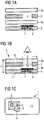
- Fig. 1 illustrates the basic principle of a security element 1
- Fig. 1a shows an exploded state before laminating
- 1b shows the condition after lamination
- Fig. 1c a view of a security element on the inner window having side.
- the basic structure consists of a functional layer 2, which is arranged between two building layers 3a, 3b. Under the constitutional layer 3b, a feature carrier layer 5 is disposed.
- the build-up layers 3a, 3b consist of a transmissive material, ie of a transparent or translucent material, or in other words of a material that is transparent to milky to the human eye, but not completely opaque.
- the functional layer 2 consists of an opaque material or at least of a material which is less transmissive than the structural layers 3a, 3b.
- the feature carrier layer 5 also consists of a opaque material or a material that is at least less transmissive than the build-up layers 3a, 3b.
- a cutout 4 is formed in the functional layer 2. He defined in the finished security element 1, an inner window 8. The cutout 4 is completely filled with material of the build-up layers 3a, 3b.
- At least one security feature 6, 7 is formed, which extends at least partially into the surface of the cutout 4. That the security feature 6, 7 lies wholly or partially in the viewing area of the inner window 8.
- the formation of the security feature 6, 7 is expediently done before connecting the feature carrier layer 5 with the other layers.
- the security feature 6, 7 may be a superficially applied security feature 6, for example in the form of a print pattern, or in the form of physical elements, such as a hologram.
- the feature layer 5 may include embedded security features 7, e.g. Color particles or fluorescent elements.
- any other known security features can be implemented in or on the feature carrier layer 5.
- features that are only visible when excited by electromagnetic radiation or features that are realized by deformation of the feature carrier layer 5 may be considered.
- some security features can be generated only after lamination, such as by lasers. It is also readily possible to form the feature carrier layer 5 in the form of a multilayer structure with a plurality of individual layers, which carry different security features. Same or different security features 6, 7 may also be formed outside of the inner window 8.
- a security feature can also already be formed by the nature of the feature carrier layer 5, in particular by its intrinsic color or surface texture.
- special, additionally introduced security features 6, 7 can be omitted and only the nature of the feature carrier layer 5 form a security feature.
- the layers 2, 3a, 3b and 5 are usually provided in the form of films.
- the sheets are laminated together to form a sheet whose shape is determined by upper and lower surfaces 10,11 and which has a small thickness compared to the size of the surfaces 10,11.
- the surfaces 10, 11 are flat and are usually plane-parallel to each other.
- Fig. 1a shows in an exploded view the layers 2, 3a, 3b, 5 of a basic structure before lamination
- Fig. 1b a sheet produced by laminating it with flat surfaces 10, 11.
- the sheet forms the body of the security element 1.
- material of the build-up layers 3a, 3b flows into the cutout 4 and fills it completely.
- the build-up layers 3a, 3b consist of a transparent and the functional layer 2 of an opaque material
- the finished security element 1 in the basic structure thus has an inner window 8, which is an observer - as in Fig. 1b indicated - easily seen when he looks in a vertical view of the surface 10 of the inner window 8 containing side of the security element 1.
- Lamination takes place with usual parameters.
- the functional layer 2 may have a plurality of free cuts 4. Each cutout 4 is bounded by a border contour 9. The geometry of the free cuts 4 can be freely selected within a wide range.
- the edge contour 9 of a cutout 4 can consist of sections of traverses, curve sections with curves in different radii and / or have angles with different opening angles.
- Fig. 1c shows a plan view of the inner window 8 having side of a security element 1.
- the illustrated shapes are purely exemplary and should not be construed in any way limiting.
- the plan illustrates the free configurability of the geometry of the cutouts 4 and of the resulting inner windows 8. These can, as indicated, have freely shaped edge contours 9.
- security features 6 can be seen, which in the example of Fig. 1c Printing patterns are.
- the field of view of a viewer when viewing the inner window 8 is limited in depth by the feature carrier layer 5.
- the thickness of the functional layer 2 is expediently below 125 .mu.m, preferably below 100 .mu.m. Bigger thicknesses are nevertheless possible.
- the thickness of the build-up layers 3 can be freely selected within a wide range. Typically, for a single make coat 3a, 3b, it is between 50 and 500 ⁇ m.
- the thickness of the build-up layers 3 adjoining a functional layer 2 with cut-free 4 is expediently selected so that the build-up layers 3 provide sufficient material to fill the cutouts 4, without resulting in an undesirable reduction in the thickness the make-up layer 3 is coming.
- the thickness of the feature carrier layer 5 typically corresponds to the thickness of a make coat and is between 50 and 500 ⁇ m.
- the total thickness H of a security element 1 is typically between 300 and 1000 microns.
- the material of the functional layer 2 is preferably polycarbonate.
- polycarbonate additives may be mixed to improve the material properties or the material behavior. Additives can be used, for example, to increase the softening temperature during lamination or to suppress shrinkage of the material.
- the build-up layers 3a, 3b are preferably made of polycarbonate; In turn, mixtures of polycarbonate with other plastics may additionally be considered.
- the polycarbonate may also be admixed with additives to improve the material properties or the material behavior.
- the build-up layers 3a, 3b also consist of the same material. In variants, it is also conceivable that the build-up layers 3a, 3b consist of different materials. It can be provided that only one of the materials during lamination flows into the free cuts 4 and fills them.
- the feature carrier layer 5 expediently also consists of polycarbonate.
- Functional layers 2 and build-up layers 3 are typically provided in the form of films that are flexible prior to lamination. During lamination, functional layers 2 and build-up layers 3 combine to form a relatively stiff sheet, but nevertheless has sufficient flexural elasticity. Suitably, the sheet satisfies the physical Specifications as they can be found in relevant standards, eg from the chip card relevant ISO 7810.
- the geometry of the cutouts 4 is slightly reduced in some cases. Corners and tip angles are typically retained.
- the shrinkage is to be considered in the design of the free cuts 4. Typically, the shrinkage is 2 to 10%.
- Fig. 1 illustrated basic structure may contain a security element 1 more functional layers 2 and 3 build-up layers and other layers of another kind.
- the layers or the surface body may also be provided with security features such as printed patterns or foreign substances or carry components, in particular optical and / or electronic components.
- the security element 1 may in particular have a standard card format and e.g. a badge, a bank, a credit or a smart card. Likewise, the security element 1 may be a SIM card, a passbook data page, a token or a key fob.
- the shape of the security element 1 is not limited to the basic shape of a rectangle but may have any other geometry and have, for example, a teardrop shape, a triangular shape or the shape of an alphanumeric character.
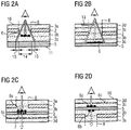
- Fig. 2 illustrates embodiments of a security element 1, in which the security element in addition to the layers 3a, 2, 3b, 5 of a basic structure still has further structural layers.
- Fig. 2a shows a variant that in principle the basic structure Fig. 1 equivalent. Unlike this, between the functional layer 2 and the feature carrier layer 5 but still another, third layer construction 3c arranged so that it is adjacent to the construction layer 3b of the basic structure. Between functional layer 2 and feature carrier layer 5, two build-up layers 3b, 3c are thus arranged adjacent to one another. In the plane between the further structural layer 3c and the adjacent structural layer 3b, a security feature 6 is formed, which, as in the Fig. 2a indicated, for example, may have the form of a print pattern. The security feature 6 is technically expediently formed on the underside of the build-up layer 3b or on the upper side of the third build-up layer 3c. It can also be realized within one of the building layers.
- Fig. 2b shows a variant in which a first additional build-up layer 3c between the feature carrier layer 5 and functional layer 2 and a second additional build-up layer 3d is arranged on the opposite side of the functional layer 2.
- a security feature in the form of a print pattern 6 is formed on the feature carrier layer 5.
- a further security feature 13 for example a hologram or a printing pattern, is formed, which in the example of FIG Fig. 2b partially located in the inner window 8.
- the inner window 8 As a recess.
- the viewer recognizes the further security feature 13 and furthermore the print pattern 6. Both overlap, the different depth position being perceived.
- the perception of the different depths is enhanced by the perception of shading.
- the shading impression arises, as based on Fig. 2a explained, by the field of view of the observer, which, as indicated by arrows, both areas that are below the further security feature 13, as well as areas that lie below the functional layer 2.
- Fig. 2c two further build-up layers 3c, 3d are arranged on the opposite side of the feature carrier layer 5.
- the functional layer 2 is opaque and has free cuts 4.
- the feature carrier layer 5 is in this case, unlike the basic structure according to Fig. 1 , not completely opaque translucent. That is, the feature carrier layer 5 has a lower opacity than the functional layer 2 and is translucent.
- Above the feature carrier layer 5 there are two further build-up layers 3c, 3d above one another.
- the build-up layer 3d forms the planar upper side 10 of the security element 1.
- the additional build-up layers 3c, 3d expediently consist of the same material as the build-up layers 3a, 3b and, like them, are transparent.
- the feature carrier layer 5 is provided with a printing pattern 6a, 6b which lies in the viewing area of the inner window 8 formed by the cutout 4.
- the print pattern 6a, 6b can, as in Fig. 3 indicated to be formed on both sides of the feature carrier layer 5.
- a further security feature is formed on the upper side of the build-up layer 3c adjoining the feature carrier layer 5, for example in the form of a further print pattern 6c, for example of a design pattern.
- a further print pattern 6c for example of a design pattern.
- a feature embedded in one or both of the build-up layers 3c, 3d may also be provided.
- Fig. 2c One - as in Fig. 2c indicated - viewed from the opposite side perpendicular to the security element 1 viewer sees in the in Fig. 2c illustrated embodiment, inner window 8 with a translucent, so at least slightly translucent rear side. Decisive for the translucent impression is the nature, more precisely: the opacity of the feature carrier layer 5. In the inner window 8, the viewer clearly recognizes the print patterns 6c and 6a; on the other hand, the print pattern 6b appears attenuated depending on the opacity of the feature carrier layer 5. In this way, the impression of a different depth of the print pattern is brought about.
- Fig. 2d shows the same basic structure as Fig. 2c in reverse order. In contrast to Fig. 2c is on the feature carrier layer 5 also a print pattern 6 only present on one side; For this purpose, additionally embedded features 7 are formed in the feature carrier layer 5, eg fluorescent elements.
- the inner window 8 translucent.
- the nature of the feature carrier layer 5 is decisive for the translucent impression.
- the viewer clearly recognizes the print pattern 6a and the embedded features 7. According to the translucency of the feature carrier layer 5, it detects the print pattern 6c in a weakened manner. This in turn supports the impression of a different depth.
- the security features 6, 7 applied asymmetrically in relation to the feature carrier layer 5, a viewer also has different appearances depending on which side the security element 1 is viewed from. So is about in Fig. 2c as viewed from the top, the print pattern 6c on the make coat 3c is well recognizable while the same print pattern 6c is poorly or not recognizable when viewed from the bottom. Likewise, alternately the printed patterns 6a, 6b applied to the feature carrier layer 5 are respectively good from one side and less recognizable from the opposite side. Are at the in Fig. 2d indicated variant the build-up layers 3a, 3b, 3c, 3d in the same way transparent, the centrally formed embedded feature 7 from both viewing sides forth equally well recognizable.
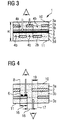
- FIG. 3 Figure 1 illustrates an embodiment of a seven-layered security element 1 simulating a security thread, such as known from banknotes.
- the security element 1 comprises a central feature carrier layer 5, which in this case is transparent and is covered on all sides with a glossy, reflective print layer 6 on one side.
- the feature support layer 5 itself is glossy and reflective. You can for this example contain metallic particles.
- a three-layer structure consisting of two build-up layers 3a, 3b or 3c, 3d and a central functional layer 2c or 2d is arranged in each case.
- Both functional layers 2c, 2d are each provided with a sequence of cutouts 4a, 4b.
- the free cuts 4a, 4b are expediently formed at regular intervals along a line.
- the sequences of cutouts 4 a, 4 b are aligned with one another in such a way that the cutouts in the respective first functional layer lie exactly opposite material regions in the respective other functional layer.
- the printing layer 6 may not be designed over the entire surface. In this case, a viewer observes the security element 1 in the cutouts 4a in accordance with the pattern of the printing layer 6 and also the full-surface areas 12b of the remote functional layer 2b true. This enhances the impression of depth.
- FIG. 4 Another, in Fig. 4 indicated variant is based on the basic structure accordingly FIG. 1 , Unlike this, however, the feature carrier layer 5 is also provided with at least one cutout, and below the feature carrier layer 5, a further make coat 3e is arranged.
- the further structural layer 3 e consists of the same material as the two other structural layers 3 a, 3 b, ie it is transparent or translucent.
- the material of the further build-up layer 3e together with the material of the other build-up layers 3a, 3b, fills the cutout in the feature carrier layer 5 and thus produces a second inner window 17 on the opposite side.
- the cutout in the feature carrier layer 5 has a different geometry than the cutout 4 in the functional layer 2. Free cut 4 and cutout in the feature carrier layer 5 partially overlap. Accordingly, the inner windows 8, 17 are partially opposite. Thereby arise in the security element 1 different adjoining areas: a see-through area 18 from the upper surface 10 to the lower surface 11, an insight area 16, the an inner window according to the basic structure according to FIG. 1 corresponds, and an insight area 19, which is limited by the functional layer 2.
- On or in the feature carrier layer 5 may in turn be arranged security features 6, 7. Also on the underside of the functional layer 2 can - not shown - in the apparent through the inner window 17 area further security features can be arranged.
- a security element 1 which is for a viewer, as in Fig. 4 indicated, from both viewing sides ago geometrically different inner windows 8, 17 shows.
- the inner windows 8, 17 also provide different views: in the inner window 8, the security feature 6, 7 can be seen, in the inner window 17 in the viewing area 19, the underside of the functional layer 2.
- the functional layer 2 can also carry security features that expedient of those in the viewing area 16 of the inner window 8 arranged security features 6, 7 differ.
- the different transparency in the backlight forms another feature characteristic of the security element 1. Maintaining the basic idea of providing interior window 8 in a multi-layered construction by providing a central functional layer 2 with cutouts 4 which, when laminated, are filled with material of the adjacent building layers 3a, 3b and further provide a feature support layer 5 which is located in the viewing area of the Window 8 carries security features 6, 7, the invention allows a number of other variants, which are not detailed here. If the invention is used in an identity card, for example, several embodiments can be realized side by side in the same card.
Landscapes
- Engineering & Computer Science (AREA)
- Manufacturing & Machinery (AREA)
- Laminated Bodies (AREA)
- Credit Cards Or The Like (AREA)
Description
Die Erfindung betrifft ein mehrschichtiges Sicherheitselement, das unter anderem als Datenseite oder als Ausweiskarte einsetzbar ist. Insbesondere betrifft die Erfindung ein mehrschichtiges Sicherheitselement in Form eines Flächenkörpers, der zumindest einen transparenten oder transluzenten Bereich aufweist. Der Bereich kann ein Fenster sein. Die Erfindung betrifft außerdem ein Verfahren zur Herstellung eines Sicherheitselementes.The invention relates to a multilayer security element which can be used, inter alia, as a data page or as an identity card. In particular, the invention relates to a multilayer security element in the form of a sheet having at least one transparent or translucent region. The area can be a window. The invention also relates to a method for producing a security element.
Ein gattungsgemäßes Sicherheitselement in Form einer Ausweiskarte ist aus der
Aus der
Aus der
Es ist Aufgabe der vorliegenden Erfindung ein als Ausweiskarte oder Datenseite verwendbares Sicherheitselement anzugeben, das ein Sicherheitsmerkmal sowie einen transparenten oder transluzenten Bereich aufweist und das einfach herstellbar ist.It is an object of the present invention to provide a security element which can be used as an identity card or data page and which has a security feature as well as a transparent or translucent area and which can be produced easily.
Diese Aufgabe wird gelöst durch ein Sicherheitselement mit den Merkmalen des Hauptanspruchs. Sie wird ebenso gelöst durch ein Verfahren mit den Merkmalen des unabhängigen Verfahrensanspruchs. Das erfindungsgemäße Sicherheitselement zeichnet sich durch eine hervorragende Planarität seiner Oberflächen aus, ohne dass zu seiner Herstellung besondere anspruchsvolle Verfahrensschritte erforderlich sind. Ein weiterer Vorteil ist, dass in einem ansonsten opaken Flächenkörper auf einfache Weise Innenfenster geschaffen werden können, in deren Einsichtbereichen Sicherheitsmerkmale ausgebildet sind. Bei entsprechender Anordnung werden die Sicherheitsmerkmale deutlich in unterschiedlichen Tiefenlagen wahrgenommen. Unterstützt wird der Eindruck einer unterschiedlichen Tiefenlage, indem die Sicherheitsmerkmale auf oder in einer Schicht ausgebildet werden, die unter Zwischenlage einer transparenten Funktionsschicht unter der das Innenfenster definierenden opaken Schicht angeordnet ist.This object is achieved by a security element having the features of the main claim. It is also solved by a method having the features of the independent method claim. The security element according to the invention is characterized by an excellent planarity of its surfaces, without that for its production special demanding Procedural steps are required. Another advantage is that in an otherwise opaque sheet body interior windows can be created in a simple manner, in the insight areas security features are formed. With appropriate arrangement, the security features are clearly perceived in different depths. Supported is the Impression of a different depth position by the security features are formed on or in a layer which is arranged with the interposition of a transparent functional layer under the inner window defining opaque layer.
Die Innenfenster können dabei nahezu beliebig gestaltete Randkonturen aufweisen. Erreicht wird dies, indem die Ausbildung von transparenten oder von transmissiven Bereichen nicht durch Bereitstellung von speziell dafür vorgesehenem transparentem oder transmissivem Material erreicht wird, sondern beim Laminieren erfolgt, indem Freischnitte mit Material der angrenzenden transmissiven Aufbauschichten aufgefüllt werden.The inner windows can have almost arbitrarily designed edge contours. This is achieved by not accomplishing the formation of transparent or transmissive areas by providing specially designed transparent or transmissive material, but by laminating by filling free cuts with material from the adjacent transmissive building layers.
Besonders gute Ergebnisse werden erreicht, wenn das Material der Funktionsschichten eine Dicke von weniger als 100 µm besitzt. Besonders vorteilhaft ist es weiter, wenn als Material für die Aufbauschichten Polycarbonat gewählt wird oder ein im wesentlichen aus Polycarbonat bestehendes Material. Besonders vorteilhaft weist das mehrschichtige Sicherheitselement zwei opake Funktionsschichten auf, die unter Zwischenlage einer Merkmalträgerschicht einander gegenüberliegen. Auf der Merkmalträgerschicht sind Sicherheitsmerkmale ausgebildet, die von beiden Seiten betrachtet werden können. Vorteilhaft können dabei unterschiedliche Wahrnehmungen realisiert werden. In einer besonders zweckmäßigen Ausgestaltung sind die Freischnitte in den Funktionsschichten so angeordnet, dass sie entlang einer Linie plaziert sind, sich jedoch nicht überlappen. Wird dazu eine Merkmalträgerschicht zwischen den Funktionsschichten angeordnet, lässt sich in vorteilhafter Weise der Effekt eines Sicherheitsfadens erzielen, wie er von Banknoten her bekannt ist.Particularly good results are achieved when the material of the functional layers has a thickness of less than 100 microns. It is particularly advantageous if polycarbonate is chosen as the material for the build-up layers or a material consisting essentially of polycarbonate. Particularly advantageously, the multilayer security element has two opaque functional layers, which lie opposite one another with the interposition of a feature carrier layer. On the feature carrier layer security features are formed, which can be viewed from both sides. Advantageously, different perceptions can be realized. In a particularly expedient embodiment, the cutouts in the functional layers are arranged so that they are placed along a line, but do not overlap. If a feature carrier layer is arranged between the functional layers for this purpose, the effect of a security thread, as known from banknotes, can advantageously be achieved.
Unter Bezugnahme auf die Zeichnung werden nachfolgend Ausführungsbeispiele der Erfindung näher erläutert. Es zeigen:
- Fig. 1
- im Querschnitt das Grundprinzip des Aufbaus eines Sicherheitselements,
- Fig. 2
- im Querschnitt Varianten eines Sicherheitselements mit weiteren Aufbauschichten und weiteren Sicherheitsmerkmalen,
- Fig. 3
- im Querschnitt ein Sicherheitselement mit zwei Funktionsschichten, die einen Sicherheitsfaden nachbilden, und
- Fig. 4
- im Querschnitt ein Sicherheitselement mit zwei sich teilweise gegenüberliegenden Innenfenstern.
- Fig. 1
- in cross-section the basic principle of the construction of a security element,
- Fig. 2
- in cross-section variants of a security element with further structural layers and other security features,
- Fig. 3
- in cross section a security element with two functional layers that simulate a security thread, and
- Fig. 4
- in cross section a security element with two partially opposite inner windows.
In der Funktionsschicht 2 ist ein Freischnitt 4 ausgebildet. Er definiert im fertigen Sicherheitselement 1 ein Innenfenster 8. Der Freischnitt 4 ist vollständig mit Material der Aufbauschichten 3a, 3b ausgefüllt.In the
Auf der Merkmalträgerschicht 5 ist zumindest ein Sicherheitsmerkmal 6, 7 ausgebildet, das sich zumindest teilweise in die Fläche des Freischnittes 4 erstreckt. D.h. das Sicherheitsmerkmal 6, 7 liegt ganz oder teilweise im Einsichtbereich des Innenfensters 8. Die Ausbildung des Sicherheitsmerkmals 6, 7 geschieht zweckmäßig vor dem Verbinden der Merkmalträgerschicht 5 mit den anderen Schichten.On the
Das Sicherheitsmerkmal 6, 7 kann ein oberflächlich aufgebrachtes Sicherheitsmerkmal 6 sein, etwa in Form eines Druckmusters, oder in Form körperlicher Elemente, etwa eines Hologramms. Alternativ oder ergänzend kann die Merkmalsschicht 5 eingebettete Sicherheitsmerkmale 7 enthalten, z.B. Farbpartikel oder fluoreszierende Elemente.The
Neben den genannten können beliebige andere bekannte Sicherheitsmerkmale in oder auf der Merkmalträgerschicht 5 realisiert sein. In Betracht kommen beispielsweise Merkmale, die nur unter Anregung mit elektromagnetischer Strahlung sichtbar werden oder Merkmale, die durch Verformung der Merkmalträgerschicht 5 realisiert sind. Auch können manche Sicherheitsmerkmale erst nach dem Laminieren erzeugt werden, etwa durch Lasern. Ohne weiteres ist es ferner möglich die Merkmalträgerschicht 5 in Form einer Mehrschichtstruktur mit mehreren Einzelschichten auszubilden, die unterschiedliche Sicherheitsmerkmale tragen. Dieselben oder andere Sicherheitsmerkmale 6, 7 können ferner auch außerhalb des Innenfensters 8 ausgebildet sein.In addition to those mentioned, any other known security features can be implemented in or on the
Ein Sicherheitsmerkmal kann auch bereits durch die Beschaffenheit der Merkmalträgerschicht 5 gebildet sein, insbesondere durch deren Eigenfarbe oder Oberflächenbeschaffenheit. In einer sehr einfachen und kostengünstigen Variante können besondere, zusätzlich eingebrachte Sicherheitsmerkmale 6, 7 entfallen und nur die Beschaffenheit der Merkmalträgerschicht 5 ein Sicherheitsmerkmal bilden.A security feature can also already be formed by the nature of the
Da sie in der Fläche des Freischnittes 4 liegen, kann - wie in
Die Schichten 2, 3a, 3b und 5 werden in der Regel in Form von Folien bereitgestellt. Die Folien werden durch Laminieren miteinander zu einem Flächenkörper verbunden, dessen Gestalt durch eine obere und eine untere Oberfläche 10, 11 bestimmt wird und eine im Vergleich zur Größe der Oberflächen 10,11 geringe Dicke aufweist. Die Oberflächen 10, 11 sind plan und liegen in der Regel planparallel zueinander.The
Die Funktionsschicht 2 kann mehrere Freischnitte 4 aufweisen. Jeder Freischnitt 4 wird durch eine Randkontur 9 begrenzt. Die Geometrie der Freischnitte 4 kann in einem weiten Rahmen frei gewählt werden. Die Randkontur 9 eines Freischnittes 4 kann dabei aus Abschnitten von Polygonzügen bestehen, Kurvenabschnitte mit Kurven in unterschiedlichen Radien enthalten und/oder Winkel mit unterschiedlichen Öffnungswinkeln aufweisen.The
Die Dicke der Funktionsschicht 2 liegt zweckmäßig bei unter 125µm, vorzugsweise bei unter 100 µm. Größere Dicken sind gleichwohl möglich. Die Dicke der Aufbauschichten 3 kann in einem weiten Bereich frei gewählt werden. Typischerweise liegt sie für eine einzelne Aufbauschicht 3a, 3b zwischen 50 und 500 µm. Die Dicke der an eine Funktionsschicht 2 mit Freischnitt 4 angrenzenden Aufbauschichten 3 ist zweckmäßig so gewählt, dass die Aufbauschichten 3 genügend Material bereitstellen, um die Freischnitte 4 aufzufüllen, ohne dass es zu einer unerwünschten Verringerung der Dicke der Aufbauschicht 3 kommt. Die Dicke der der Merkmalträgerschicht 5 entspricht typischerweise der Dicke einer Aufbauschicht und liegt zwischen 50 und 500 µm. Die Gesamtdicke H eines Sicherheitselementes 1 liegt typischerweise zwischen 300 und 1000 µm.The thickness of the
Das Material der Funktionsschicht 2 ist bevorzugt Polycarbonat. Alternativ kommen ggf. Mischungen von Polycarbonat mit anderen Kunststoffen in Betracht. Dem Polycarbonat können Zusätze zur Verbesserung der Materialeigenschaften oder des Materialverhaltens beigemischt sein. Zusätze können etwa dazu dienen, beim Laminieren die Erweichungstemperatur heraufzusetzen oder eine Schrumpfung des Materials zu unterdrücken.The material of the
Ebenso bestehen die Aufbauschichten 3a, 3b bevorzugt aus Polycarbonat; wiederum kommen daneben ggf. Mischungen von Polycarbonat mit anderen Kunststoffen in Betracht. Dem Polycarbonat können ebenfalls Zusätze zur Verbesserung der Materialeigenschaften oder des Materialverhaltens beigemischt sein. Zweckmäßig bestehen die Aufbauschichten 3a, 3b ferner aus demselben Material. In Varianten ist auch denkbar, dass die Aufbauschichten 3a, 3b aus unterschiedlichen Materialien bestehen. Dabei kann vorgesehen sein, dass nur eines der Materialien beim Laminieren in die Freischnitte 4 fließt und diese ausfüllt.Likewise, the build-up
Die Merkmalträgerschicht 5 besteht zweckmäßig ebenfalls aus Polycarbonat.The
Funktionsschichten 2 und Aufbauschichten 3 werden typischerweise in Form von Folien bereitgestellt, die vor dem Laminieren flexibel sind. Beim Laminieren verbinden sich Funktionsschichten 2 und Aufbauschichten 3 zu einem relativ steifen Flächenkörper, der aber dennoch eine ausreichende Biegeelastizität besitzt. Zweckmäßig genügt der Flächenkörper den physikalischen Vorgaben, wie sie aus einschlägigen Normen entnehmbar sind, z.B. aus der für Chipkarten einschlägigen ISO 7810.
Beim Laminieren kommt es in manchen Fällen zu einer leichten Schrumpfung der Geometrien der Freischnitte 4. Ecken und Spitze Winkel bleiben dabei typischerweise erhalten. Die Schrumpfung ist bei der Gestaltung der Freischnitte 4 zu berücksichtigen. Typischerweise beträgt die Schrumpfung 2 bis 10 %.During lamination, the geometry of the
Ausgehend von dem in
Das Sicherheitselement 1 kann insbesondere ein Standardkartenformat besitzen und z.B. eine Ausweis-, eine Bank-, eine Kredit-oder eine Chipkarte sein. Ebenso kann das Sicherheitselement 1 eine SIM-Karte, eine Datenseite für einen Passbuch, eine Token oder ein Schlüsselanhänger sein. Die Form des Sicherheitselements 1 ist dabei nicht auf die Grundform eines Rechtecks beschränkt sondern kann beliebige andere Geometrie aufweisen und zum Beispiel eine Tropfenform, eine Dreiecksform oder die Gestalt eines alphanumerischen Zeichens besitzen.The
Sieht ein Betrachter - wie in
Der durch die Verschattung bewirkte Effekt einer großen Tiefe tritt in gleicher Weise auch bei den anderen Ausführungsformen gemäß den
Einem - wie in
Die Ausführung nach
In
Desweiteren ist auf der Oberseite der an die Merkmalträgerschicht 5 angrenzenden Aufbauschicht 3c ein weiteres Sicherheitsmerkmal ausgebildet, zum Beispiel in Gestalt eines weiteren Druckmusters 6c, etwa eines Designmusters. Anstelle eines Druckmusters 6c oder zusätzlich dazu kann auch ein in eine oder beide der Aufbauschichten 3c, 3d eingebettetes Merkmal vorgesehen sein.Furthermore, a further security feature is formed on the upper side of the build-up
Ein - wie in
Einem - wie in
Durch die in Bezug auf die Merkmalträgerschicht 5 asymmetrisch aufgebrachten Sicherheitsmerkmale 6, 7 ergeben sich für einen Betrachter zudem unterschiedliche Erscheinungsbilder abhängig davon, von welcher Seite das Sicherheitselement 1 betrachtet wird. So ist etwa in
Die Ausführungen nach den
Zu beiden Seiten der zentralen Merkmalträgerschicht 5 ist jeweils ein Dreischichtaufbau bestehend aus zwei Aufbauschichten 3a, 3b bzw. 3c, 3d und einer mittigen Funktionsschicht 2c bzw. 2d angeordnet. Beide Funktionsschichten 2c, 2d sind jeweils mit einer Folge von Freischnitten 4a, 4b versehen. Die Freischnitte 4a, 4b sind zweckmäßig jeweils in regelmäßigen Abständen entlang einer Linie ausgebildet. Die Folgen von Freischnitten 4a, 4b sind so zueinander ausgerichtet, dass die Freischnitte in der jeweils ersten Funktionsschicht genau Materialbereichen in der jeweils anderen Funktionsschicht gegenüberliegen.On both sides of the central
Blickt ein Betrachter - wie in der Fig. angedeutet - in lotrechter Aufsicht auf die Oberfläche 10 des Sicherheitselements 1, sieht er durch die transparente Aufbauschicht 3a zum einen die vollflächigen Bereiche 12a in der nächstliegenden Funktionsschicht 2a. In den dazwischenliegenden Freischnitten 4a sieht er zum anderen jeweils Abschnitte der glänzenden, auf der Merkmalträgerschicht 5 ausgebildeten Druckschicht 6. Diese Abschnitte der Merkmalträgerschicht 5 liegen dabei klar wahrnehmbar in einer größeren Tiefe als die vollflächigen Bereiche 12a der Funktionsschicht 2.If an observer looks at the
In einer Variante kann die Druckschicht 6 nicht vollflächig gestaltet sein. In diesem Fall nimmt ein Betrachter bei Aufsicht auf das Sicherheitselement 1 in den Freischnitten 4a entsprechend dem Muster der Druckschicht 6 auch die vollflächigen Bereiche 12b der abgewandten Funktionsschicht 2b wahr. Dadurch verstärkt sich der Tiefeneindruck.In a variant, the
Eine weitere, in
Der Ausschnitt in der Merkmalträgerschicht 5 besitzt eine andere Geometrie als der Freischnitt 4 in der Funktionsschicht 2. Freischnitt 4 und Ausschnitt in der Merkmalträgerschicht 5 überlagern sich teilweise. Entsprechend liegen sich die Innenfenster 8, 17 teilweise gegenüber. Es entstehen dadurch in dem Sicherheitselement 1 unterschiedliche aneinander angrenzende Bereiche: ein Durchsichtbereich 18 von der oberen Oberfläche 10 bis zu unteren Oberfläche 11, ein Einsichtbereich 16, der einem Innenfenster gemäß dem Grundaufbau nach
Die in
Die Einsichtbereiche 16, 19, in denen sich die Funktionsschicht 2 und die Merkmalschicht 5 nicht überlagern, erscheinen zudem bei Betrachtung im Gegenlicht als geringer opak im Vergleich zu den umliegenden Bereichen, in denen sich Funktionsschicht 2 und die Merkmalschicht 5 überlagern. Die unterschiedliche Transparenz im Gegenlicht bildet ein weiteres für das Sicherheitselement 1 charakteristisches Merkmal.
Unter Beibehaltung des grundlegenden Gedankens, in einem Mehrschichtaufbau Innenfenster 8 zu schaffen, indem eine zentrale Funktionsschicht 2 mit Freischnitten 4 versehen wird, die beim Laminieren durch Material der angrenzenden Aufbauschichten 3a, 3b aufgefüllt werden, und weiter eine Merkmalträgerschicht 5 vorzusehen, die im Einsichtbereich des Fensters 8 Sicherheitsmerkmale 6, 7 trägt, gestattet die Erfindung eine Reihe von weiteren Varianten, die hier nicht im einzelnen ausgeführt sind. Wird die Erfindung etwa in einer Ausweiskarte eingesetzt, können in derselben Karte nebeneinander mehrere Ausführungsformen realisiert sein. Grundsätzlich gibt es keine Beschränkung hinsichtlich der Anzahl der übereinander angeordneten Sets von Funktions- und Aufbauschichten bzw. der Anzahl von übereinander angeordneten Grundaufbauten. Insbesondere lassen sich durch Einbringen von weiteren transparenten Aufbauschichten gezielt weitere Ebenen in einem Sicherheitselement erzeugen, auf denen Sicherheitsmerkmale ausgebildet werden können. Durch geeignete Kombination von Schichtfolgen in entsprechenden Materialien lässt sich eine Vielzahl von Durchsicht- und Tiefeneffekten erzeugen. Insbesondere können unterschiedliche Durchsicht- oder Tiefeneffekte auf demselben Sicherheitselement 1 realisiert sein. Ferner ist es selbstverständlich möglich, ein Sicherheitselement 1 mit Innenfenstern 8 nach seiner Fertigstellung mit weiteren Merkmalen zu versehen, die insbesondere auch oder über in den Innenfenstern angeordnet sein können. Beispiele für solche Merkmale sind etwa Personalisierung-oder Individualisierungsinformationen. Für die einzelnen Schichten 2, 3a, 3b, 5 können weiterhin auch andere, insbesondere für die Herstellung von Karten bekannte Materialien eingesetzt werden. Allerdings kann es bei Verwendung anderer Materialien erforderlich sein, in den Freischnitten 4 Einleger vorzusehen, um zu gewährleisten, dass das fertige Sicherheitselement 1 plane Oberflächen 10, 11 aufweist. In Versuchen erwies sich die Verwendung von Einlegern bei der Verwendung von PVC als zweckmäßig.The
Maintaining the basic idea of providing
Claims (15)
- A multilayer security element with an opaque functional layer (2) arranged between two build-up layers (3a, 3b) of a transmissive material, wherein the layers (2, 3a, 3b) are connected by lamination to form an areal body with planar surfaces (10, 11), wherein the opaque functional layer (2) has at least one cutout (4) and the at least one cutout (4) is filled up with transmissive material of the build-up layers (3a, 3b), characterized in that on one of the build-up layers (3a, 3b) there is further arranged a feature carrier layer (5), and in the feature carrier layer (5) and/ or on the feature carrier layer (5) between the feature carrier layer (5) and the functional layer (2) a security feature (6, 7) is formed which extends at least partially into the area of the at least one cutout (4).
- The multilayer security element according to claim 1, characterized in that between the functional layer (2) and the feature carrier layer (5), there is arranged a further build-up layer (3c) of a transmissive material which adjoins another build-up layer (3b), and at least one security element (6) is arranged between the third build-up layer (3c) and the adjoining build-up layer (3b).
- The multilayer security element according to claim 1 or 2, characterized in that the opaque functional layer (2) has a thickness of less than 150 µm.
- The multilayer security element according to claim 1 or 2, characterized in that the build-up layers (3a, 3b) consist completely or substantially of polycarbonate.
- The multilayer security element according to claim 1 or 2, characterized in that it has at least one further build-up layer (3c, 3d) of transmissive material, and a further, second opaque functional layer (2a, 2b) and the further functional layer (2a, 2b) likewise has at least one cutout (4).
- The multilayer security element according to claim 5, characterized in that the further build-up layer (3c, 3d) and the further functional layer (2) are arranged on the side of the feature carrier layer (5) that faces away.
- The multilayer security element according to claim 5, characterized in that the positions of the cutouts (4) in the functional layers (2) are arranged offset from one another without overlap.
- The multilayer security element according to claim 1 or 2, characterized in that on one side of a build-up layer (3c) facing away from the feature carrier layer (5) there is arranged a further transmissive build-up layer (3d) and a security feature (6c) is formed between the build-up layers (3c, 3d).
- The multilayer security element according to claim 1 or 2, characterized in that on or in a further build-up layer (3d), a further security feature (13) is formed which extends at least partially over the area of the cutout (4).
- The multilayer security element according to any of the preceding claims, characterized in that at least one build-up layer (3a, 3b, 3c, 3d) consists of a transparent material.
- The multilayer security element according to any of the preceding claims, characterized in that the feature carrier layer (5) is likewise equipped with at least one gap, and below the feature carrier layer (5) there is arranged a further build-up layer (3e) of a transmissive material, wherein the at least one gap is filled up with transmissive material of the build-up layers (3b, 3e).
- A method for manufacturing a multilayer security element with an areal body with planar surfaces, characterized by the following steps of:- making available an opaque functional layer (2) in which at least one cutout (4) is prepared,- making available two transparent build-up layers (3a, 3b),- making available a feature carrier layer (5),- forming a security feature (6) in the feature carrier layer (5) and/or on the feature carrier layer (5) between the feature carrier layer (5) and the functional layer (2),- placing above one another the functional layer (2), the build-up layers (3a, 3b) and the feature carrier layer (5), so that the security feature (6, 7) extends at least partially into the area of the at least one cutout (4),- laminating the layers (2, 3a, 3b, 5) placed above one another to form an areal body, such that during lamination the material of the build-up layers (3a, 3b) fills up the cutout (4) in the opaque functional layer (2).
- The method according to claim 12, characterized in that the cutout (4) in the opaque functional layer (2) made available is dimensioned such that a shrinkage occurring during lamination is taken account of.
- The method according to claim 12, characterized in that the feature carrier layer (5) forms a security feature through its properties or a security feature (6, 7) is formed on and/or in the feature carrier layer (5).
- The method according to claim 12, characterized by the following further steps of:- making available a further, third build-up layer (3c),- placing the further build-up layer (3c) between the feature carrier layer (5) and the functional layer (2) so that it adjoins another build-up layer (3b), and- arranging at least one security element (6) between the further build-up layer (3c) and the adjoining build-up layer (3b).
Applications Claiming Priority (2)
| Application Number | Priority Date | Filing Date | Title |
|---|---|---|---|
| DE102015005082.6A DE102015005082A1 (en) | 2015-04-21 | 2015-04-21 | Multilayer security element |
| PCT/EP2016/000641 WO2016169650A1 (en) | 2015-04-21 | 2016-04-20 | Multilayer security element |
Publications (2)
| Publication Number | Publication Date |
|---|---|
| EP3286012A1 EP3286012A1 (en) | 2018-02-28 |
| EP3286012B1 true EP3286012B1 (en) | 2019-03-20 |
Family
ID=55794932
Family Applications (1)
| Application Number | Title | Priority Date | Filing Date |
|---|---|---|---|
| EP16717258.4A Revoked EP3286012B1 (en) | 2015-04-21 | 2016-04-20 | Multilayer security element |
Country Status (4)
| Country | Link |
|---|---|
| US (1) | US10336123B2 (en) |
| EP (1) | EP3286012B1 (en) |
| DE (1) | DE102015005082A1 (en) |
| WO (1) | WO2016169650A1 (en) |
Cited By (1)
| Publication number | Priority date | Publication date | Assignee | Title |
|---|---|---|---|---|
| DE102023100676B3 (en) | 2023-01-12 | 2024-03-07 | Melzer Maschinenbau Gmbh | Security element for a security document |
Families Citing this family (7)
| Publication number | Priority date | Publication date | Assignee | Title |
|---|---|---|---|---|
| DE102015010811A1 (en) * | 2015-08-21 | 2017-02-23 | Veridos Gmbh | Multi-layered data carrier with a flat see-through window |
| DE102016003181A1 (en) * | 2016-03-15 | 2017-09-21 | Giesecke+Devrient Mobile Security Gmbh | Card-shaped data carrier |
| US10272712B2 (en) * | 2017-05-09 | 2019-04-30 | Abcorp Na Inc. | Plastic card with security feature |
| US10479128B2 (en) * | 2017-10-27 | 2019-11-19 | Assa Abloy Ab | Security feature |
| GB2576218B (en) * | 2018-08-10 | 2021-09-15 | De La Rue Int Ltd | Security devices and methods of authentication thereof |
| EP3663098A1 (en) | 2018-12-05 | 2020-06-10 | HID Global CID SAS | Identification document data page and related production method |
| US20230347680A1 (en) * | 2022-04-28 | 2023-11-02 | Valaurum, Inc. | Metallic sheet with security window and methods of manufacture |
Citations (14)
| Publication number | Priority date | Publication date | Assignee | Title |
|---|---|---|---|---|
| EP0219011A2 (en) | 1985-10-15 | 1987-04-22 | GAO Gesellschaft für Automation und Organisation mbH | Identity card with a visually detectable authenticity feature, and method of making it |
| US6210777B1 (en) | 1993-12-10 | 2001-04-03 | Agfa-Gevaert | Security document having a transparent or translucent support and containing interference pigments |
| DE602004000286T2 (en) | 2003-02-24 | 2006-08-24 | Sdu Identification B.V. | IDENTITY CARD AND TRAVEL DOCUMENT |
| EP1698485A2 (en) | 2005-03-04 | 2006-09-06 | Canadian Bank Note Company, Ltd. | Identification document with lenticular watermark |
| EP1719637A2 (en) | 2005-05-06 | 2006-11-08 | Canadian Bank Note Company, Ltd. | Security document with ultraviolet authentication security feature |
| EP1935663A1 (en) | 2006-12-18 | 2008-06-25 | Setec Oy | Data carrier with see-through window and method for producing it |
| WO2010070084A1 (en) | 2008-12-18 | 2010-06-24 | Gemalto Oy | Identification document with an improved anti-counterfeiting element |
| EP2559563A1 (en) | 2011-08-18 | 2013-02-20 | Polska Wytwornia Papierow Wartosciowych S.A. | A security document with a see-through feature, and methods for manufacturing and authentication thereof |
| DE102012204340A1 (en) | 2012-03-19 | 2013-09-19 | Bundesdruckerei Gmbh | Security document with a perforation window and method for its production |
| US20140097253A1 (en) | 2012-10-05 | 2014-04-10 | Ask S.A. | Process for manufacturing a contactless smartcard having a transparent logo |
| EP2178707B1 (en) | 2007-08-10 | 2014-05-14 | Bundesdruckerei GmbH | Security document having watermark-like structure |
| WO2014081280A2 (en) | 2012-11-21 | 2014-05-30 | Lim Pooi Nguon | Information medium and a method of producing the same |
| EP2681054B1 (en) | 2011-03-01 | 2014-09-10 | Bundesdruckerei GmbH | Composite body and method for producing a composite body having an internal security feature |
| WO2014203199A1 (en) | 2013-06-20 | 2014-12-24 | Arjowiggins Security | Multilayer security structure and associated method of production |
Family Cites Families (9)
| Publication number | Priority date | Publication date | Assignee | Title |
|---|---|---|---|---|
| JP2005031721A (en) * | 2003-07-07 | 2005-02-03 | Konica Minolta Photo Imaging Inc | Ic card and method for producing it |
| GB2452078B (en) * | 2007-08-23 | 2009-12-23 | Rue De Int Ltd | Security devices for security substrates |
| DE102008013073B4 (en) * | 2008-03-06 | 2011-02-03 | Leonhard Kurz Stiftung & Co. Kg | Process for producing a film element and film element |
| US8324031B2 (en) * | 2008-06-24 | 2012-12-04 | Globalfoundries Singapore Pte. Ltd. | Diffusion barrier and method of formation thereof |
| FR2947211B1 (en) | 2009-06-29 | 2011-08-26 | Oberthur Technologies | SECURITY DOCUMENT AND VERIFICATION METHOD OF THIS DOCUMENT |
| FR2948217B1 (en) * | 2009-07-17 | 2011-11-11 | Arjowiggins Security | SECURITY ELEMENT WITH PARALLAX EFFECT |
| EP2378073A1 (en) * | 2010-04-14 | 2011-10-19 | Siemens Aktiengesellschaft | Blade or vane for a turbomachine |
| AU2013277753B2 (en) * | 2012-06-21 | 2015-04-09 | 3M Innovative Properties Company | A static dissipating laser engravable film |
| WO2015042586A1 (en) * | 2013-09-23 | 2015-03-26 | Morphotrust Usa, Llc | Unidirectional opacity watermark |
-
2015
- 2015-04-21 DE DE102015005082.6A patent/DE102015005082A1/en active Pending
-
2016
- 2016-04-20 EP EP16717258.4A patent/EP3286012B1/en not_active Revoked
- 2016-04-20 WO PCT/EP2016/000641 patent/WO2016169650A1/en active Application Filing
- 2016-04-20 US US15/568,308 patent/US10336123B2/en active Active
Patent Citations (17)
| Publication number | Priority date | Publication date | Assignee | Title |
|---|---|---|---|---|
| EP0219011A2 (en) | 1985-10-15 | 1987-04-22 | GAO Gesellschaft für Automation und Organisation mbH | Identity card with a visually detectable authenticity feature, and method of making it |
| US6210777B1 (en) | 1993-12-10 | 2001-04-03 | Agfa-Gevaert | Security document having a transparent or translucent support and containing interference pigments |
| DE602004000286T2 (en) | 2003-02-24 | 2006-08-24 | Sdu Identification B.V. | IDENTITY CARD AND TRAVEL DOCUMENT |
| EP1698485A2 (en) | 2005-03-04 | 2006-09-06 | Canadian Bank Note Company, Ltd. | Identification document with lenticular watermark |
| EP1719637A2 (en) | 2005-05-06 | 2006-11-08 | Canadian Bank Note Company, Ltd. | Security document with ultraviolet authentication security feature |
| EP1935663A1 (en) | 2006-12-18 | 2008-06-25 | Setec Oy | Data carrier with see-through window and method for producing it |
| WO2008075164A2 (en) | 2006-12-18 | 2008-06-26 | Gemalto Oy | Data carrier with see-through window and method for producing it |
| EP2178707B1 (en) | 2007-08-10 | 2014-05-14 | Bundesdruckerei GmbH | Security document having watermark-like structure |
| WO2010070084A1 (en) | 2008-12-18 | 2010-06-24 | Gemalto Oy | Identification document with an improved anti-counterfeiting element |
| EP2681054B1 (en) | 2011-03-01 | 2014-09-10 | Bundesdruckerei GmbH | Composite body and method for producing a composite body having an internal security feature |
| EP2559563A1 (en) | 2011-08-18 | 2013-02-20 | Polska Wytwornia Papierow Wartosciowych S.A. | A security document with a see-through feature, and methods for manufacturing and authentication thereof |
| EP2559563B1 (en) | 2011-08-18 | 2014-03-26 | Polska Wytwornia Papierow Wartosciowych S.A. | A security document with a see-through feature, and methods for manufacturing and authentication thereof |
| DE102012204340A1 (en) | 2012-03-19 | 2013-09-19 | Bundesdruckerei Gmbh | Security document with a perforation window and method for its production |
| US20140097253A1 (en) | 2012-10-05 | 2014-04-10 | Ask S.A. | Process for manufacturing a contactless smartcard having a transparent logo |
| WO2014081280A2 (en) | 2012-11-21 | 2014-05-30 | Lim Pooi Nguon | Information medium and a method of producing the same |
| WO2014203199A1 (en) | 2013-06-20 | 2014-12-24 | Arjowiggins Security | Multilayer security structure and associated method of production |
| FR3007318A1 (en) * | 2013-06-20 | 2014-12-26 | Arjowiggins Security | MULTILAYER SAFETY STRUCTURE AND METHOD OF MANUFACTURING THE SAME |
Cited By (1)
| Publication number | Priority date | Publication date | Assignee | Title |
|---|---|---|---|---|
| DE102023100676B3 (en) | 2023-01-12 | 2024-03-07 | Melzer Maschinenbau Gmbh | Security element for a security document |
Also Published As
| Publication number | Publication date |
|---|---|
| WO2016169650A1 (en) | 2016-10-27 |
| US20180147881A1 (en) | 2018-05-31 |
| EP3286012A1 (en) | 2018-02-28 |
| US10336123B2 (en) | 2019-07-02 |
| DE102015005082A1 (en) | 2016-10-27 |
Similar Documents
| Publication | Publication Date | Title |
|---|---|---|
| EP3286012B1 (en) | Multilayer security element | |
| EP0219011B1 (en) | Identity card with a visually detectable authenticity feature, and method of making it | |
| DE602004000286T2 (en) | IDENTITY CARD AND TRAVEL DOCUMENT | |
| EP1827868B1 (en) | Card-shaped data carrier | |
| EP2178707B1 (en) | Security document having watermark-like structure | |
| EP1322480A1 (en) | Recording medium | |
| DE10338444A1 (en) | Transponder inlay for a document for personal identification and method for its production | |
| DE102015010811A1 (en) | Multi-layered data carrier with a flat see-through window | |
| EP1747101B1 (en) | Multilayered portable data carrier | |
| EP2384898B1 (en) | Safety element for security papers, valuable documents or the like | |
| DE102012020056B4 (en) | Book-type value and / or security document with elastomeric spine | |
| DE102014017535A1 (en) | Identification document with information from thermochromic ink and method for producing an identification document and method for verifying an identification document | |
| EP3915778B1 (en) | Coextruded fluorescent film | |
| EP3666542B1 (en) | Laminate and method for producing a laminate, and security or valuable document having an interior security feature | |
| DE102016012115A1 (en) | Multilayer card body | |
| EP3645302B1 (en) | Security element comprising a printed image with a three-dimensional effect | |
| WO2020233749A1 (en) | Security element with anamorphically modified image | |
| EP3418067A1 (en) | Fluorescent personalisation by means of a laser | |
| WO2021028168A1 (en) | Document of value or security document and method for the production thereof | |
| EP4357147A1 (en) | Data page with security hinge | |
| DE10342276A1 (en) | Security document and method for producing a security document | |
| EP3782822A1 (en) | Microstructured transparent security element | |
| EP4364037A1 (en) | Method for producing a chip card body | |
| WO2023016670A1 (en) | Method for the production of a security feature, security feature for a data medium, data medium, and lamination sheet | |
| EP3717272A1 (en) | Layer arrangement having a metal layer in the window region |
Legal Events
| Date | Code | Title | Description |
|---|---|---|---|
| STAA | Information on the status of an ep patent application or granted ep patent |
Free format text: STATUS: THE INTERNATIONAL PUBLICATION HAS BEEN MADE |
|
| PUAI | Public reference made under article 153(3) epc to a published international application that has entered the european phase |
Free format text: ORIGINAL CODE: 0009012 |
|
| STAA | Information on the status of an ep patent application or granted ep patent |
Free format text: STATUS: REQUEST FOR EXAMINATION WAS MADE |
|
| 17P | Request for examination filed |
Effective date: 20171121 |
|
| AK | Designated contracting states |
Kind code of ref document: A1 Designated state(s): AL AT BE BG CH CY CZ DE DK EE ES FI FR GB GR HR HU IE IS IT LI LT LU LV MC MK MT NL NO PL PT RO RS SE SI SK SM TR |
|
| AX | Request for extension of the european patent |
Extension state: BA ME |
|
| RIN1 | Information on inventor provided before grant (corrected) |
Inventor name: ROSATI, TOBIAS Inventor name: ENDRES, GUENTER Inventor name: KOHL, KLAUS |
|
| TPAC | Observations filed by third parties |
Free format text: ORIGINAL CODE: EPIDOSNTIPA |
|
| DAV | Request for validation of the european patent (deleted) | ||
| DAX | Request for extension of the european patent (deleted) | ||
| GRAP | Despatch of communication of intention to grant a patent |
Free format text: ORIGINAL CODE: EPIDOSNIGR1 |
|
| STAA | Information on the status of an ep patent application or granted ep patent |
Free format text: STATUS: GRANT OF PATENT IS INTENDED |
|
| INTG | Intention to grant announced |
Effective date: 20181019 |
|
| GRAS | Grant fee paid |
Free format text: ORIGINAL CODE: EPIDOSNIGR3 |
|
| GRAA | (expected) grant |
Free format text: ORIGINAL CODE: 0009210 |
|
| STAA | Information on the status of an ep patent application or granted ep patent |
Free format text: STATUS: THE PATENT HAS BEEN GRANTED |
|
| AK | Designated contracting states |
Kind code of ref document: B1 Designated state(s): AL AT BE BG CH CY CZ DE DK EE ES FI FR GB GR HR HU IE IS IT LI LT LU LV MC MK MT NL NO PL PT RO RS SE SI SK SM TR |
|
| REG | Reference to a national code |
Ref country code: GB Ref legal event code: FG4D Free format text: NOT ENGLISH |
|
| REG | Reference to a national code |
Ref country code: CH Ref legal event code: EP |
|
| REG | Reference to a national code |
Ref country code: DE Ref legal event code: R096 Ref document number: 502016003825 Country of ref document: DE |
|
| REG | Reference to a national code |
Ref country code: AT Ref legal event code: REF Ref document number: 1110142 Country of ref document: AT Kind code of ref document: T Effective date: 20190415 |
|
| REG | Reference to a national code |
Ref country code: IE Ref legal event code: FG4D Free format text: LANGUAGE OF EP DOCUMENT: GERMAN |
|
| REG | Reference to a national code |
Ref country code: NL Ref legal event code: MP Effective date: 20190320 |
|
| PG25 | Lapsed in a contracting state [announced via postgrant information from national office to epo] |
Ref country code: SE Free format text: LAPSE BECAUSE OF FAILURE TO SUBMIT A TRANSLATION OF THE DESCRIPTION OR TO PAY THE FEE WITHIN THE PRESCRIBED TIME-LIMIT Effective date: 20190320 Ref country code: NO Free format text: LAPSE BECAUSE OF FAILURE TO SUBMIT A TRANSLATION OF THE DESCRIPTION OR TO PAY THE FEE WITHIN THE PRESCRIBED TIME-LIMIT Effective date: 20190620 Ref country code: FI Free format text: LAPSE BECAUSE OF FAILURE TO SUBMIT A TRANSLATION OF THE DESCRIPTION OR TO PAY THE FEE WITHIN THE PRESCRIBED TIME-LIMIT Effective date: 20190320 Ref country code: LT Free format text: LAPSE BECAUSE OF FAILURE TO SUBMIT A TRANSLATION OF THE DESCRIPTION OR TO PAY THE FEE WITHIN THE PRESCRIBED TIME-LIMIT Effective date: 20190320 |
|
| REG | Reference to a national code |
Ref country code: LT Ref legal event code: MG4D |
|
| PG25 | Lapsed in a contracting state [announced via postgrant information from national office to epo] |
Ref country code: HR Free format text: LAPSE BECAUSE OF FAILURE TO SUBMIT A TRANSLATION OF THE DESCRIPTION OR TO PAY THE FEE WITHIN THE PRESCRIBED TIME-LIMIT Effective date: 20190320 Ref country code: GR Free format text: LAPSE BECAUSE OF FAILURE TO SUBMIT A TRANSLATION OF THE DESCRIPTION OR TO PAY THE FEE WITHIN THE PRESCRIBED TIME-LIMIT Effective date: 20190621 Ref country code: NL Free format text: LAPSE BECAUSE OF FAILURE TO SUBMIT A TRANSLATION OF THE DESCRIPTION OR TO PAY THE FEE WITHIN THE PRESCRIBED TIME-LIMIT Effective date: 20190320 Ref country code: BG Free format text: LAPSE BECAUSE OF FAILURE TO SUBMIT A TRANSLATION OF THE DESCRIPTION OR TO PAY THE FEE WITHIN THE PRESCRIBED TIME-LIMIT Effective date: 20190620 Ref country code: LV Free format text: LAPSE BECAUSE OF FAILURE TO SUBMIT A TRANSLATION OF THE DESCRIPTION OR TO PAY THE FEE WITHIN THE PRESCRIBED TIME-LIMIT Effective date: 20190320 Ref country code: RS Free format text: LAPSE BECAUSE OF FAILURE TO SUBMIT A TRANSLATION OF THE DESCRIPTION OR TO PAY THE FEE WITHIN THE PRESCRIBED TIME-LIMIT Effective date: 20190320 |
|
| PG25 | Lapsed in a contracting state [announced via postgrant information from national office to epo] |
Ref country code: SK Free format text: LAPSE BECAUSE OF FAILURE TO SUBMIT A TRANSLATION OF THE DESCRIPTION OR TO PAY THE FEE WITHIN THE PRESCRIBED TIME-LIMIT Effective date: 20190320 Ref country code: RO Free format text: LAPSE BECAUSE OF FAILURE TO SUBMIT A TRANSLATION OF THE DESCRIPTION OR TO PAY THE FEE WITHIN THE PRESCRIBED TIME-LIMIT Effective date: 20190320 Ref country code: CZ Free format text: LAPSE BECAUSE OF FAILURE TO SUBMIT A TRANSLATION OF THE DESCRIPTION OR TO PAY THE FEE WITHIN THE PRESCRIBED TIME-LIMIT Effective date: 20190320 Ref country code: IT Free format text: LAPSE BECAUSE OF FAILURE TO SUBMIT A TRANSLATION OF THE DESCRIPTION OR TO PAY THE FEE WITHIN THE PRESCRIBED TIME-LIMIT Effective date: 20190320 Ref country code: EE Free format text: LAPSE BECAUSE OF FAILURE TO SUBMIT A TRANSLATION OF THE DESCRIPTION OR TO PAY THE FEE WITHIN THE PRESCRIBED TIME-LIMIT Effective date: 20190320 Ref country code: PT Free format text: LAPSE BECAUSE OF FAILURE TO SUBMIT A TRANSLATION OF THE DESCRIPTION OR TO PAY THE FEE WITHIN THE PRESCRIBED TIME-LIMIT Effective date: 20190720 Ref country code: ES Free format text: LAPSE BECAUSE OF FAILURE TO SUBMIT A TRANSLATION OF THE DESCRIPTION OR TO PAY THE FEE WITHIN THE PRESCRIBED TIME-LIMIT Effective date: 20190320 Ref country code: AL Free format text: LAPSE BECAUSE OF FAILURE TO SUBMIT A TRANSLATION OF THE DESCRIPTION OR TO PAY THE FEE WITHIN THE PRESCRIBED TIME-LIMIT Effective date: 20190320 |
|
| PG25 | Lapsed in a contracting state [announced via postgrant information from national office to epo] |
Ref country code: PL Free format text: LAPSE BECAUSE OF FAILURE TO SUBMIT A TRANSLATION OF THE DESCRIPTION OR TO PAY THE FEE WITHIN THE PRESCRIBED TIME-LIMIT Effective date: 20190320 Ref country code: SM Free format text: LAPSE BECAUSE OF FAILURE TO SUBMIT A TRANSLATION OF THE DESCRIPTION OR TO PAY THE FEE WITHIN THE PRESCRIBED TIME-LIMIT Effective date: 20190320 |
|
| REG | Reference to a national code |
Ref country code: CH Ref legal event code: PL |
|
| REG | Reference to a national code |
Ref country code: BE Ref legal event code: MM Effective date: 20190430 |
|
| REG | Reference to a national code |
Ref country code: DE Ref legal event code: R026 Ref document number: 502016003825 Country of ref document: DE |
|
| PG25 | Lapsed in a contracting state [announced via postgrant information from national office to epo] |
Ref country code: IS Free format text: LAPSE BECAUSE OF FAILURE TO SUBMIT A TRANSLATION OF THE DESCRIPTION OR TO PAY THE FEE WITHIN THE PRESCRIBED TIME-LIMIT Effective date: 20190720 Ref country code: LU Free format text: LAPSE BECAUSE OF NON-PAYMENT OF DUE FEES Effective date: 20190420 |
|
| PLBI | Opposition filed |
Free format text: ORIGINAL CODE: 0009260 |
|
| PLAX | Notice of opposition and request to file observation + time limit sent |
Free format text: ORIGINAL CODE: EPIDOSNOBS2 |
|
| PLAB | Opposition data, opponent's data or that of the opponent's representative modified |
Free format text: ORIGINAL CODE: 0009299OPPO |
|
| PG25 | Lapsed in a contracting state [announced via postgrant information from national office to epo] |
Ref country code: LI Free format text: LAPSE BECAUSE OF NON-PAYMENT OF DUE FEES Effective date: 20190430 Ref country code: CH Free format text: LAPSE BECAUSE OF NON-PAYMENT OF DUE FEES Effective date: 20190430 Ref country code: DK Free format text: LAPSE BECAUSE OF FAILURE TO SUBMIT A TRANSLATION OF THE DESCRIPTION OR TO PAY THE FEE WITHIN THE PRESCRIBED TIME-LIMIT Effective date: 20190320 Ref country code: MC Free format text: LAPSE BECAUSE OF FAILURE TO SUBMIT A TRANSLATION OF THE DESCRIPTION OR TO PAY THE FEE WITHIN THE PRESCRIBED TIME-LIMIT Effective date: 20190320 |
|
| 26 | Opposition filed |
Opponent name: BUNDESDRUCKEREI GMBH Effective date: 20191220 Opponent name: MUEHLBAUER GMBH & CO. KG Effective date: 20191220 |
|
| R26 | Opposition filed (corrected) |
Opponent name: MUEHLBAUER GMBH & CO. KG Effective date: 20191220 |
|
| PG25 | Lapsed in a contracting state [announced via postgrant information from national office to epo] |
Ref country code: BE Free format text: LAPSE BECAUSE OF NON-PAYMENT OF DUE FEES Effective date: 20190430 Ref country code: SI Free format text: LAPSE BECAUSE OF FAILURE TO SUBMIT A TRANSLATION OF THE DESCRIPTION OR TO PAY THE FEE WITHIN THE PRESCRIBED TIME-LIMIT Effective date: 20190320 |
|
| PG25 | Lapsed in a contracting state [announced via postgrant information from national office to epo] |
Ref country code: TR Free format text: LAPSE BECAUSE OF FAILURE TO SUBMIT A TRANSLATION OF THE DESCRIPTION OR TO PAY THE FEE WITHIN THE PRESCRIBED TIME-LIMIT Effective date: 20190320 |
|
| PG25 | Lapsed in a contracting state [announced via postgrant information from national office to epo] |
Ref country code: IE Free format text: LAPSE BECAUSE OF NON-PAYMENT OF DUE FEES Effective date: 20190420 |
|
| PLBB | Reply of patent proprietor to notice(s) of opposition received |
Free format text: ORIGINAL CODE: EPIDOSNOBS3 |
|
| RDAF | Communication despatched that patent is revoked |
Free format text: ORIGINAL CODE: EPIDOSNREV1 |
|
| APBM | Appeal reference recorded |
Free format text: ORIGINAL CODE: EPIDOSNREFNO |
|
| APBP | Date of receipt of notice of appeal recorded |
Free format text: ORIGINAL CODE: EPIDOSNNOA2O |
|
| APAH | Appeal reference modified |
Free format text: ORIGINAL CODE: EPIDOSCREFNO |
|
| APBQ | Date of receipt of statement of grounds of appeal recorded |
Free format text: ORIGINAL CODE: EPIDOSNNOA3O |
|
| GBPC | Gb: european patent ceased through non-payment of renewal fee |
Effective date: 20200420 |
|
| PG25 | Lapsed in a contracting state [announced via postgrant information from national office to epo] |
Ref country code: GB Free format text: LAPSE BECAUSE OF NON-PAYMENT OF DUE FEES Effective date: 20200420 |
|
| PG25 | Lapsed in a contracting state [announced via postgrant information from national office to epo] |
Ref country code: CY Free format text: LAPSE BECAUSE OF FAILURE TO SUBMIT A TRANSLATION OF THE DESCRIPTION OR TO PAY THE FEE WITHIN THE PRESCRIBED TIME-LIMIT Effective date: 20190320 |
|
| PG25 | Lapsed in a contracting state [announced via postgrant information from national office to epo] |
Ref country code: MT Free format text: LAPSE BECAUSE OF FAILURE TO SUBMIT A TRANSLATION OF THE DESCRIPTION OR TO PAY THE FEE WITHIN THE PRESCRIBED TIME-LIMIT Effective date: 20190320 Ref country code: HU Free format text: LAPSE BECAUSE OF FAILURE TO SUBMIT A TRANSLATION OF THE DESCRIPTION OR TO PAY THE FEE WITHIN THE PRESCRIBED TIME-LIMIT; INVALID AB INITIO Effective date: 20160420 |
|
| REG | Reference to a national code |
Ref country code: AT Ref legal event code: MM01 Ref document number: 1110142 Country of ref document: AT Kind code of ref document: T Effective date: 20210420 |
|
| PG25 | Lapsed in a contracting state [announced via postgrant information from national office to epo] |
Ref country code: MK Free format text: LAPSE BECAUSE OF FAILURE TO SUBMIT A TRANSLATION OF THE DESCRIPTION OR TO PAY THE FEE WITHIN THE PRESCRIBED TIME-LIMIT Effective date: 20190320 |
|
| PG25 | Lapsed in a contracting state [announced via postgrant information from national office to epo] |
Ref country code: AT Free format text: LAPSE BECAUSE OF NON-PAYMENT OF DUE FEES Effective date: 20210420 |
|
| RAP4 | Party data changed (patent owner data changed or rights of a patent transferred) |
Owner name: GIESECKE+DEVRIENT MOBILE SECURITY GMBH |
|
| P01 | Opt-out of the competence of the unified patent court (upc) registered |
Effective date: 20230520 |
|
| REG | Reference to a national code |
Ref country code: DE Ref legal event code: R103 Ref document number: 502016003825 Country of ref document: DE Ref country code: DE Ref legal event code: R064 Ref document number: 502016003825 Country of ref document: DE |
|
| APBU | Appeal procedure closed |
Free format text: ORIGINAL CODE: EPIDOSNNOA9O |
|
| REG | Reference to a national code |
Ref country code: DE Ref legal event code: R081 Ref document number: 502016003825 Country of ref document: DE Owner name: GIESECKE+DEVRIENT EPAYMENTS GMBH, DE Free format text: FORMER OWNER: GIESECKE+DEVRIENT MOBILE SECURITY GMBH, 81677 MUENCHEN, DE |
|
| PGFP | Annual fee paid to national office [announced via postgrant information from national office to epo] |
Ref country code: FR Payment date: 20230417 Year of fee payment: 8 Ref country code: DE Payment date: 20230430 Year of fee payment: 8 |
|
| RAP4 | Party data changed (patent owner data changed or rights of a patent transferred) |
Owner name: GIESECKE+DEVRIENT EPAYMENTS GMBH |
|
| RDAG | Patent revoked |
Free format text: ORIGINAL CODE: 0009271 |
|
| STAA | Information on the status of an ep patent application or granted ep patent |
Free format text: STATUS: PATENT REVOKED |
|
| REG | Reference to a national code |
Ref country code: CH Ref legal event code: PL |
|
| 27W | Patent revoked |
Effective date: 20230710 |
|
| REG | Reference to a national code |
Ref country code: AT Ref legal event code: MA03 Ref document number: 1110142 Country of ref document: AT Kind code of ref document: T Effective date: 20230710 |