EP3285241A2 - System and method for processing traffic sound data to provide driver assistance - Google Patents
System and method for processing traffic sound data to provide driver assistance Download PDFInfo
- Publication number
- EP3285241A2 EP3285241A2 EP17186060.4A EP17186060A EP3285241A2 EP 3285241 A2 EP3285241 A2 EP 3285241A2 EP 17186060 A EP17186060 A EP 17186060A EP 3285241 A2 EP3285241 A2 EP 3285241A2
- Authority
- EP
- European Patent Office
- Prior art keywords
- vehicle
- sound
- audio
- vehicles
- ecu
- Prior art date
- Legal status (The legal status is an assumption and is not a legal conclusion. Google has not performed a legal analysis and makes no representation as to the accuracy of the status listed.)
- Granted
Links
- 238000000034 method Methods 0.000 title claims abstract description 51
- 238000012545 processing Methods 0.000 title claims description 14
- 238000012546 transfer Methods 0.000 claims description 6
- 230000008569 process Effects 0.000 abstract description 18
- 238000004891 communication Methods 0.000 description 56
- 230000005236 sound signal Effects 0.000 description 33
- 230000005540 biological transmission Effects 0.000 description 24
- 230000008859 change Effects 0.000 description 12
- 238000013459 approach Methods 0.000 description 9
- 238000004458 analytical method Methods 0.000 description 8
- 241000282414 Homo sapiens Species 0.000 description 7
- 230000000875 corresponding effect Effects 0.000 description 7
- 238000001514 detection method Methods 0.000 description 7
- 238000010586 diagram Methods 0.000 description 6
- 230000006870 function Effects 0.000 description 6
- 241001465754 Metazoa Species 0.000 description 5
- 230000002411 adverse Effects 0.000 description 4
- 238000004590 computer program Methods 0.000 description 3
- 230000007774 longterm Effects 0.000 description 3
- 241000283690 Bos taurus Species 0.000 description 2
- 230000009471 action Effects 0.000 description 2
- 230000003190 augmentative effect Effects 0.000 description 2
- 230000008901 benefit Effects 0.000 description 2
- 230000001934 delay Effects 0.000 description 2
- 238000011161 development Methods 0.000 description 2
- 238000005516 engineering process Methods 0.000 description 2
- 239000000446 fuel Substances 0.000 description 2
- 239000000463 material Substances 0.000 description 2
- 239000013308 plastic optical fiber Substances 0.000 description 2
- 239000004984 smart glass Substances 0.000 description 2
- 238000012549 training Methods 0.000 description 2
- 241000282412 Homo Species 0.000 description 1
- UFHFLCQGNIYNRP-UHFFFAOYSA-N Hydrogen Chemical compound [H][H] UFHFLCQGNIYNRP-UHFFFAOYSA-N 0.000 description 1
- 101100172132 Mus musculus Eif3a gene Proteins 0.000 description 1
- 230000006399 behavior Effects 0.000 description 1
- 238000004364 calculation method Methods 0.000 description 1
- 230000010267 cellular communication Effects 0.000 description 1
- 230000001413 cellular effect Effects 0.000 description 1
- 238000006243 chemical reaction Methods 0.000 description 1
- 239000000470 constituent Substances 0.000 description 1
- 230000002596 correlated effect Effects 0.000 description 1
- 230000006378 damage Effects 0.000 description 1
- 230000034994 death Effects 0.000 description 1
- 231100000517 death Toxicity 0.000 description 1
- 230000001419 dependent effect Effects 0.000 description 1
- 230000009977 dual effect Effects 0.000 description 1
- 239000000428 dust Substances 0.000 description 1
- 210000005069 ears Anatomy 0.000 description 1
- 230000000694 effects Effects 0.000 description 1
- 239000002803 fossil fuel Substances 0.000 description 1
- 229910052739 hydrogen Inorganic materials 0.000 description 1
- 239000001257 hydrogen Substances 0.000 description 1
- 230000009474 immediate action Effects 0.000 description 1
- 230000010365 information processing Effects 0.000 description 1
- 238000002347 injection Methods 0.000 description 1
- 239000007924 injection Substances 0.000 description 1
- 238000009434 installation Methods 0.000 description 1
- 238000010801 machine learning Methods 0.000 description 1
- 238000005259 measurement Methods 0.000 description 1
- 238000010295 mobile communication Methods 0.000 description 1
- 238000012986 modification Methods 0.000 description 1
- 230000004048 modification Effects 0.000 description 1
- 230000006855 networking Effects 0.000 description 1
- 230000008520 organization Effects 0.000 description 1
- 239000002245 particle Substances 0.000 description 1
- 230000002093 peripheral effect Effects 0.000 description 1
- 230000009467 reduction Effects 0.000 description 1
- 238000012552 review Methods 0.000 description 1
- 230000001360 synchronised effect Effects 0.000 description 1
- 230000000007 visual effect Effects 0.000 description 1
- 230000003245 working effect Effects 0.000 description 1
Images


Classifications
-
- B—PERFORMING OPERATIONS; TRANSPORTING
- B60—VEHICLES IN GENERAL
- B60W—CONJOINT CONTROL OF VEHICLE SUB-UNITS OF DIFFERENT TYPE OR DIFFERENT FUNCTION; CONTROL SYSTEMS SPECIALLY ADAPTED FOR HYBRID VEHICLES; ROAD VEHICLE DRIVE CONTROL SYSTEMS FOR PURPOSES NOT RELATED TO THE CONTROL OF A PARTICULAR SUB-UNIT
- B60W50/00—Details of control systems for road vehicle drive control not related to the control of a particular sub-unit, e.g. process diagnostic or vehicle driver interfaces
- B60W50/08—Interaction between the driver and the control system
- B60W50/14—Means for informing the driver, warning the driver or prompting a driver intervention
-
- G—PHYSICS
- G08—SIGNALLING
- G08G—TRAFFIC CONTROL SYSTEMS
- G08G1/00—Traffic control systems for road vehicles
- G08G1/09—Arrangements for giving variable traffic instructions
- G08G1/0962—Arrangements for giving variable traffic instructions having an indicator mounted inside the vehicle, e.g. giving voice messages
- G08G1/0968—Systems involving transmission of navigation instructions to the vehicle
-
- B—PERFORMING OPERATIONS; TRANSPORTING
- B60—VEHICLES IN GENERAL
- B60K—ARRANGEMENT OR MOUNTING OF PROPULSION UNITS OR OF TRANSMISSIONS IN VEHICLES; ARRANGEMENT OR MOUNTING OF PLURAL DIVERSE PRIME-MOVERS IN VEHICLES; AUXILIARY DRIVES FOR VEHICLES; INSTRUMENTATION OR DASHBOARDS FOR VEHICLES; ARRANGEMENTS IN CONNECTION WITH COOLING, AIR INTAKE, GAS EXHAUST OR FUEL SUPPLY OF PROPULSION UNITS IN VEHICLES
- B60K35/00—Instruments specially adapted for vehicles; Arrangement of instruments in or on vehicles
- B60K35/20—Output arrangements, i.e. from vehicle to user, associated with vehicle functions or specially adapted therefor
- B60K35/29—Instruments characterised by the way in which information is handled, e.g. showing information on plural displays or prioritising information according to driving conditions
-
- B—PERFORMING OPERATIONS; TRANSPORTING
- B60—VEHICLES IN GENERAL
- B60R—VEHICLES, VEHICLE FITTINGS, OR VEHICLE PARTS, NOT OTHERWISE PROVIDED FOR
- B60R16/00—Electric or fluid circuits specially adapted for vehicles and not otherwise provided for; Arrangement of elements of electric or fluid circuits specially adapted for vehicles and not otherwise provided for
- B60R16/02—Electric or fluid circuits specially adapted for vehicles and not otherwise provided for; Arrangement of elements of electric or fluid circuits specially adapted for vehicles and not otherwise provided for electric constitutive elements
-
- B—PERFORMING OPERATIONS; TRANSPORTING
- B60—VEHICLES IN GENERAL
- B60W—CONJOINT CONTROL OF VEHICLE SUB-UNITS OF DIFFERENT TYPE OR DIFFERENT FUNCTION; CONTROL SYSTEMS SPECIALLY ADAPTED FOR HYBRID VEHICLES; ROAD VEHICLE DRIVE CONTROL SYSTEMS FOR PURPOSES NOT RELATED TO THE CONTROL OF A PARTICULAR SUB-UNIT
- B60W30/00—Purposes of road vehicle drive control systems not related to the control of a particular sub-unit, e.g. of systems using conjoint control of vehicle sub-units
- B60W30/14—Adaptive cruise control
- B60W30/16—Control of distance between vehicles, e.g. keeping a distance to preceding vehicle
-
- B—PERFORMING OPERATIONS; TRANSPORTING
- B60—VEHICLES IN GENERAL
- B60W—CONJOINT CONTROL OF VEHICLE SUB-UNITS OF DIFFERENT TYPE OR DIFFERENT FUNCTION; CONTROL SYSTEMS SPECIALLY ADAPTED FOR HYBRID VEHICLES; ROAD VEHICLE DRIVE CONTROL SYSTEMS FOR PURPOSES NOT RELATED TO THE CONTROL OF A PARTICULAR SUB-UNIT
- B60W30/00—Purposes of road vehicle drive control systems not related to the control of a particular sub-unit, e.g. of systems using conjoint control of vehicle sub-units
- B60W30/18—Propelling the vehicle
- B60W30/18009—Propelling the vehicle related to particular drive situations
- B60W30/18163—Lane change; Overtaking manoeuvres
-
- G—PHYSICS
- G01—MEASURING; TESTING
- G01S—RADIO DIRECTION-FINDING; RADIO NAVIGATION; DETERMINING DISTANCE OR VELOCITY BY USE OF RADIO WAVES; LOCATING OR PRESENCE-DETECTING BY USE OF THE REFLECTION OR RERADIATION OF RADIO WAVES; ANALOGOUS ARRANGEMENTS USING OTHER WAVES
- G01S11/00—Systems for determining distance or velocity not using reflection or reradiation
- G01S11/14—Systems for determining distance or velocity not using reflection or reradiation using ultrasonic, sonic, or infrasonic waves
-
- G—PHYSICS
- G08—SIGNALLING
- G08G—TRAFFIC CONTROL SYSTEMS
- G08G1/00—Traffic control systems for road vehicles
- G08G1/09—Arrangements for giving variable traffic instructions
- G08G1/0962—Arrangements for giving variable traffic instructions having an indicator mounted inside the vehicle, e.g. giving voice messages
- G08G1/0965—Arrangements for giving variable traffic instructions having an indicator mounted inside the vehicle, e.g. giving voice messages responding to signals from another vehicle, e.g. emergency vehicle
-
- G—PHYSICS
- G08—SIGNALLING
- G08G—TRAFFIC CONTROL SYSTEMS
- G08G1/00—Traffic control systems for road vehicles
- G08G1/09—Arrangements for giving variable traffic instructions
- G08G1/0962—Arrangements for giving variable traffic instructions having an indicator mounted inside the vehicle, e.g. giving voice messages
- G08G1/0968—Systems involving transmission of navigation instructions to the vehicle
- G08G1/0969—Systems involving transmission of navigation instructions to the vehicle having a display in the form of a map
-
- G—PHYSICS
- G08—SIGNALLING
- G08G—TRAFFIC CONTROL SYSTEMS
- G08G1/00—Traffic control systems for road vehicles
- G08G1/16—Anti-collision systems
-
- G—PHYSICS
- G08—SIGNALLING
- G08G—TRAFFIC CONTROL SYSTEMS
- G08G1/00—Traffic control systems for road vehicles
- G08G1/16—Anti-collision systems
- G08G1/166—Anti-collision systems for active traffic, e.g. moving vehicles, pedestrians, bikes
-
- B—PERFORMING OPERATIONS; TRANSPORTING
- B60—VEHICLES IN GENERAL
- B60K—ARRANGEMENT OR MOUNTING OF PROPULSION UNITS OR OF TRANSMISSIONS IN VEHICLES; ARRANGEMENT OR MOUNTING OF PLURAL DIVERSE PRIME-MOVERS IN VEHICLES; AUXILIARY DRIVES FOR VEHICLES; INSTRUMENTATION OR DASHBOARDS FOR VEHICLES; ARRANGEMENTS IN CONNECTION WITH COOLING, AIR INTAKE, GAS EXHAUST OR FUEL SUPPLY OF PROPULSION UNITS IN VEHICLES
- B60K2360/00—Indexing scheme associated with groups B60K35/00 or B60K37/00 relating to details of instruments or dashboards
- B60K2360/18—Information management
- B60K2360/186—Displaying information according to relevancy
-
- B—PERFORMING OPERATIONS; TRANSPORTING
- B60—VEHICLES IN GENERAL
- B60W—CONJOINT CONTROL OF VEHICLE SUB-UNITS OF DIFFERENT TYPE OR DIFFERENT FUNCTION; CONTROL SYSTEMS SPECIALLY ADAPTED FOR HYBRID VEHICLES; ROAD VEHICLE DRIVE CONTROL SYSTEMS FOR PURPOSES NOT RELATED TO THE CONTROL OF A PARTICULAR SUB-UNIT
- B60W50/00—Details of control systems for road vehicle drive control not related to the control of a particular sub-unit, e.g. process diagnostic or vehicle driver interfaces
- B60W50/08—Interaction between the driver and the control system
- B60W50/14—Means for informing the driver, warning the driver or prompting a driver intervention
- B60W2050/143—Alarm means
-
- B—PERFORMING OPERATIONS; TRANSPORTING
- B60—VEHICLES IN GENERAL
- B60W—CONJOINT CONTROL OF VEHICLE SUB-UNITS OF DIFFERENT TYPE OR DIFFERENT FUNCTION; CONTROL SYSTEMS SPECIALLY ADAPTED FOR HYBRID VEHICLES; ROAD VEHICLE DRIVE CONTROL SYSTEMS FOR PURPOSES NOT RELATED TO THE CONTROL OF A PARTICULAR SUB-UNIT
- B60W50/00—Details of control systems for road vehicle drive control not related to the control of a particular sub-unit, e.g. process diagnostic or vehicle driver interfaces
- B60W50/08—Interaction between the driver and the control system
- B60W50/14—Means for informing the driver, warning the driver or prompting a driver intervention
- B60W2050/146—Display means
-
- B—PERFORMING OPERATIONS; TRANSPORTING
- B60—VEHICLES IN GENERAL
- B60W—CONJOINT CONTROL OF VEHICLE SUB-UNITS OF DIFFERENT TYPE OR DIFFERENT FUNCTION; CONTROL SYSTEMS SPECIALLY ADAPTED FOR HYBRID VEHICLES; ROAD VEHICLE DRIVE CONTROL SYSTEMS FOR PURPOSES NOT RELATED TO THE CONTROL OF A PARTICULAR SUB-UNIT
- B60W2554/00—Input parameters relating to objects
- B60W2554/80—Spatial relation or speed relative to objects
-
- B—PERFORMING OPERATIONS; TRANSPORTING
- B60—VEHICLES IN GENERAL
- B60Y—INDEXING SCHEME RELATING TO ASPECTS CROSS-CUTTING VEHICLE TECHNOLOGY
- B60Y2302/00—Responses or measures related to driver conditions
- B60Y2302/03—Actuating a signal or alarm device
-
- B—PERFORMING OPERATIONS; TRANSPORTING
- B60—VEHICLES IN GENERAL
- B60Y—INDEXING SCHEME RELATING TO ASPECTS CROSS-CUTTING VEHICLE TECHNOLOGY
- B60Y2400/00—Special features of vehicle units
- B60Y2400/90—Driver alarms
Definitions
- Embodiments of the present disclosure relate to audio processing and systems and methods for processing of traffic sound data for driving assistance.
- Driving a vehicle may be a cumbersome and difficult task for a significant section of the population.
- a constant focus may be required to drive on a traffic situation on a road and to adhere to traffic rules, such as driving in proper lanes, keeping to speed limits, and risk-free overtaking.
- traffic rules such as driving in proper lanes, keeping to speed limits, and risk-free overtaking.
- several road accident surveys across various geographies and time periods have revealed that number of deaths and injuries in road accidents is alarmingly high.
- safety on the roads may be of paramount importance to vehicle manufacturers, vehicle owners, passengers, and drivers.
- With the development of automobile and allied industries several products have been developed, which may be installed in the vehicles to guide vehicle drivers to drive cautiously.
- a system and a method to process traffic sound data for driving assistance substantially as shown in, and/or described in connection with, at least one of the figures, as set forth more completely in the claims.
- Exemplary aspects of the disclosure may comprise a method that may be implemented in an electronic control unit (ECU) of a first vehicle.
- the method may include receipt of sound data captured by two or more audio-input devices associated with the first vehicle.
- the sound data may correspond to sound emanated from one or more other vehicles.
- a distance of the first vehicle from a second vehicle of the one or more other vehicles may be determined based on the received sound data.
- an in-vehicle alert may be generated for the first vehicle based on the determined distance.
- the in-vehicle alert may comprise a virtual sound representative of sound emanated from the second vehicle.
- the first vehicle may include a first set of audio-output devices and a second set of audio-output devices.
- the first set of audio-output devices may be associated with a driver of the first vehicle, whereas the second set of audio-output devices may be associated with the driver and one or more co-passengers of the first vehicle.
- the in-vehicle alert may be reproduced via the first set of audio-output devices for the driver of the first vehicle.
- the in-vehicle alert may additionally or alternatively be reproduced via the second set of audio-output devices based on a traffic situation associated with a travel path of the first vehicle.
- Examples of the in-vehicle alert may further include, but not limited to, an accident warning, a driving-maneuver instruction, a speed-change recommendation, a vehicle-overtake recommendation, a lane-change recommendation, driving-condition information, an obstacle warning, and/or a selected vehicle tracking
- a relative position and/or an angle of the second vehicle with respect to the first vehicle may be determined. The determination of the relative position and/or the angle may be based on the received sound data. Further, a Head-Related Transfer Function (HRTF) may be applied based on the determined distance and/or the angle for the reproduction of the virtual sound representative of the sound emanated from the second vehicle.
- HRTF Head-Related Transfer Function
- a type of the second vehicle may be determined based on a comparison of a pre-stored audio signature(s) associated with the second vehicle and the sound emanated from the second vehicle.
- the virtual sound of the in-vehicle alert may be reproduced in accordance with the determined type of the second vehicle. Further, the virtual sound may be reproduced when the determined distance between the first vehicle and the second vehicle is less than a pre-specified threshold distance.
- speed of the one or more other vehicles may be determined based on the captured sound emanated from the one or more other vehicle.
- a relative velocity of the second vehicle with respect to the first vehicle may be determined based on the sound emanated from the second vehicle.
- an audio warning may be generated for the driver of the first vehicle, along with the virtual sound, based on the determined distance and/or the relative velocity.
- one or more image-capturing devices associated with the first vehicle may capture one or more images that may comprise the one or more objects in a travel path of the first vehicle.
- the one or more objects such as human beings, an animal, or other objects, may be recognized based on the one or more images captured by the one or more image-capturing devices associated with the first vehicle. Further, a distance of the one or more objects from the first vehicle may be determined based on the captured one or more images.
- the in-vehicle alert may further include a second audio-output indicative of a presence of the one or more objects in the travel path within a pre-specified distance from the first vehicle.
- display of a virtual object via an infotainment system of the first vehicle may be controlled, based on the captured one or more images.
- the virtual object may be representative of the recognized one or more objects present in the travel path of the first vehicle.
- the in-vehicle alert may include an indication of such recognized one or more objects present in the travel path of the first vehicle.
- at least the second vehicle may be displayed on a map via the infotainment system of the first vehicle. The display of the second vehicle on the map may be controlled based on the captured one or more images and the determined distance between the first vehicle and the second vehicle.
- the determined distance between the first vehicle and the second vehicle may include the relative position and/or the angle of the first vehicle with respect to the second vehicle.
- a user of the infotainment system may select a specific vehicle that is to be tracked by one or more sensors of the first vehicle, such as audio capture devices and image capture devices.
- the user of the infotainment system may either be the driver of the first vehicle or one of the one or more co-passengers of the first vehicle.
- the relative position of the user-selected specific vehicle may be tracked with respect to the first vehicle based on an audio and/or one or more images captured from the user-selected specific vehicle by the one or more sensors of the first vehicle. Thereafter, the tracked relative position of the user-selected specific vehicle may be provided to the user through the in-vehicle alert and/or displayed on the map via the infotainment system of the first vehicle.
- information that may correspond to a traffic condition associated with the travel path of the first vehicle may be transmitted to a traffic management server and/or an electronic device of a user.
- the transmission of the traffic condition information may be based on the determined distance, the relative velocity, and/or the type of the second vehicle.
- the transmission of the traffic condition information may be further based on a count of the one or more other vehicles within a pre-determined distance from the first vehicle.
- FIG. 1 is a diagram that illustrates a network environment to process traffic sound data to provide in-vehicle driver assistance, in accordance with an embodiment of the disclosure.
- the network environment 100 may include a plurality of vehicles 102, a cloud server 104, a wireless communication network 106, and one or more users.
- the plurality of vehicles 102 may include a first vehicle 102a and one or more other vehicles, such as a second vehicle 102b.
- an electronic control unit (ECU) 108 two or more audio-input devices 110a to 110h, image-capturing devices 112a to 112b in the first vehicle 102a.
- ECU electronice control unit
- the one or more users may include a driver 114 associated with the first vehicle 102a, and another driver 116 associated with the second vehicle 102b.
- the plurality of vehicles 102 may traverse along a road portion 118.
- RSU road side unit
- the ECU 108 may be communicatively coupled to the two or more audio-input devices 110a to 110h and the one or more image-capturing devices 112a to 112b, directly or indirectly via an in-vehicle network of the first vehicle 102a.
- the ECU 108 may be communicatively coupled to the RSU 120, via the wireless communication network 106.
- the RSU 120 may communicate with the cloud server 104 via the Internet or a suitable communication protocol known in the art.
- the ECU 108 may be configured to communicate with the cloud server 104 by use of the RSU 120.
- the one or more image-capturing devices 112a to 112b may not be provided in the first vehicle 102a.
- the plurality of vehicles 102 may include the first vehicle 102a, the second vehicle 102b, and other vehicles that may traverse along the road portion 118.
- the plurality of vehicles 102 may be communicatively coupled to the wireless communication network 106.
- the wireless communication network 106 may be used for a vehicle to vehicle (V2V) communication among the plurality of vehicles 102.
- the wireless communication network 106 may also be used for a vehicle to infrastructure (V21) communication between one of the plurality of vehicles 102 and the RSU 120.
- the first vehicle 102a may be an autonomous vehicle that may operate in an autonomous mode, a semi-autonomous mode, or a manual mode. Alternatively, the first vehicle 102a may be a non-autonomous vehicle.
- the first vehicle 102a may comprise the ECU 108, which may be configured to communicate with the cloud server 104, and/or one or more other vehicles of the plurality of vehicles 102, via the wireless communication network 106.
- Examples of the plurality of vehicles 102 (which include the first vehicle 102a and the second vehicle 102b) may include, but are not limited to, a motor vehicle, a hybrid vehicle, and/or a vehicle that uses one or more distinct renewable or non-renewable power sources.
- a vehicle that uses renewable or non-renewable power sources may include a fossil fuel-based vehicle, an electric propulsion-based vehicle, a hydrogen fuel-based vehicle, a solar-powered vehicle, and/or a vehicle powered by other forms of alternative energy sources.
- the cloud server 104 may comprise suitable logic, circuitry, interfaces, and/or code that may be configured to establish a communication channel with one or more vehicles, such as the first vehicle 102a.
- the cloud server 104 may be configured to store information received from the one or more vehicles, such as the first vehicle 102a.
- the cloud server 104 may be a web server, a database server, a file server, an application server, a cloud-based server, or a combination thereof.
- the cloud server 104 may be implemented by use of several technologies that are well known to those skilled in the art.
- the wireless communication network 106 may include a medium through which the first vehicle 102a may communicate with the RSU 120, the cloud server 104, and/or one or more other vehicles, such as the second vehicle 102b.
- Examples of the wireless communication network 106 may include, but are not limited to, a dedicated short-range communication (DSRC) network, a mobile ad-hoc network (MANET), a vehicular ad-hoc network (VANET), Intelligent vehicular ad-hoc network (InVANET), Internet based mobile ad-hoc networks (IMANET), a wireless sensor network (WSN), a wireless mesh network (WMN), the Internet, a cellular network, such as a long-term evolution (LTE) network, a cloud network, a Wireless Fidelity (Wi-Fi) network, and/or a Wireless Local Area Network (WLAN).
- DSRC dedicated short-range communication
- MANET mobile ad-hoc network
- VANET vehicular ad-hoc network
- InVANET Intelligent vehicular
- wireless communication protocols may include, but are not limited to, IEEE 802.11, 802.11p, 802.15, 802.16, 1609, Worldwide Interoperability for Microwave Access (Wi-MAX), Wireless Access in Vehicular Environments (WAVE), cellular communication protocols, Transmission Control Protocol and Internet Protocol (TCP/IP), User Datagram Protocol (UDP), Hypertext Transfer Protocol (HTTP), Long-term Evolution (LTE), File Transfer Protocol (FTP), ZigBee, EDGE, infrared (IR), Near-Field Communication (NFC), and/or Bluetooth (BT) communication protocols.
- IEEE 802.11, 802.11p, 802.15, 802.16, 1609 Worldwide Interoperability for Microwave Access (Wi-MAX), Wireless Access in Vehicular Environments (WAVE), cellular communication protocols, Transmission Control Protocol and Internet Protocol (TCP/IP), User Datagram Protocol (UDP), Hypertext Transfer Protocol (HTTP), Long-term Evolution (LTE), File Transfer Protocol (FTP), ZigBee, EDGE, infrared (IR
- the ECU 108 may comprise suitable logic, circuitry, interfaces, and/or code that may be configured to process sound data for driver assistance.
- the ECU 108 may receive sound data captured by the two or more audio-input devices 110a to 110h.
- the sound data may be the sound emanated by one or more other vehicles, such as the second vehicle 102b, in the road portion 118.
- the ECU 108 may determine a distance of the first vehicle 102a and the one or more other vehicles in a vicinity of the first vehicle 102a. Further, the ECU 108 may generate an in-vehicle alert for the first vehicle 102a based on the determined distance.
- the in-vehicle alert may comprise a virtual sound representative of sound emanated from at least one of the one or more other nearby vehicles, such as the second vehicle 102b.
- the ECU 108 may be further configured to access sensor data of the first vehicle 102a, or to communicate one or more control commands to other ECUs, components, or systems of the first vehicle 102a.
- the sensor data may be accessed by the ECU 108, via an in-vehicle network, such as a controller area network (CAN) bus.
- the ECU 108 may be configured to receive vehicle data from one or more connected vehicles from the plurality of vehicles 102 in a vehicle-to-vehicle (V2V) communication, via a wireless communication system.
- V2V vehicle-to-vehicle
- the ECU 108 may be configured to receive vehicle data of one or more connected vehicles from the cloud server 104in an infrastructure-to-vehicle (I2V) communication.
- the one or more connected vehicles from the plurality of vehicles 102 may communicate corresponding vehicle data to the cloud server 104 beforehand, in a vehicle-to-infrastructure (V2I) communication.
- V2I vehicle-to-inf
- the two or more audio-input devices 110a to 110h may refer to sensors, microphones, or transducers that convert sound energy into electrical signals.
- the two or more audio-input devices 110a to 110h may be configured to capture sound emanated from the one or more automobiles, such as, but not limited to, a two wheeler, a three wheeler, a four wheeler, a truck, and/or a trailer.
- the one or more automobiles may include other vehicles in the plurality of vehicles 102.
- the two or more audio-input devices 110a to 110h may capture the sound based on measurement of sound pressure and/or acoustic particle velocity of a sound field, such as a sound wave of the emanated sound.
- Sound emanated from automobiles may comprise a certain distinct pitch and loudness values generated by engine, tires, horn, or other components of the automobile.
- the two or more audio-input devices 110a to 110h may comprise audio filters that may be configured to capture sounds (such as engine or tire sounds) in pre-defined range of pitch, loudness, and sound duration such as to filter out other noise on the road portion 118.
- the two or more audio-input devices 110a to 110h may be positioned in the first vehicle 102a to capture sound from various directions around the first vehicle 102a, as shown in FIG. 1 .
- the two or more audio-input devices 110a to 110h may be communicatively coupled to the ECU 108.
- the two or more audio-input devices 110a to 110h may send sound data associated with the captured sound to the ECU 108 for further processing.
- the two or more image-capturing devices 110a to 110h may be collectively referred to as audio-input devices 110.
- the one or more image-capturing devices 112a to 112b may comprise suitable logic, circuitry, interfaces, and/or code that may be configured to capture one or more video streams of a road portion, such as the road portion 118.
- the video streams may include a plurality of image frames of one or more fields-of-view (FOVs) of the one or more image-capturing devices 112a to 112b.
- the one or more image-capturing devices 112a to 112b may be configured to record time of capture of each frame of the plurality of image frames in the captured one or more video streams.
- Examples of the one or more image-capturing devices 112a to 112b may include, but are not limited to, an image sensor, a wide-angle camera, a closed-circuit television (CCTV) camera, a camcorder, an in-built camera of a smart-glass, and/or other such vehicle cameras.
- the image-capturing devices 112a and 112b may be installed at outside rear view mirrors (ORVM) of the first vehicle 102a (as shown). Though not shown in FIG. 1 , the image-capturing devices may also include one or more other cameras installed at the front, the rear, and the sides of the vehicle body of the first vehicle 102a. For instance, the one or more other cameras may be installed at locations adjacent to that of the two or more audio-input devices 110a to 110h.
- one rotatable image-capturing device may be provided that may be configured to capture a 360 degree view of the road portion 118 in the vicinity of the first vehicle 102a.
- the one or more image-capturing devices 112a to 112b may be collectively referred to as image-capturing devices 112.
- the RSU 120 may be configured to wirelessly communicate to the plurality of vehicles 102 on the road portion 118.
- the RSU 120 may be further configured to communicate with the cloud server 104 via the Internet, or a suitable communication protocol known in the art.
- the RSU 120 may correspond to an infrastructure unit or a communication device installed at the road portion 118. In accordance with an embodiment, multiple RSUs similar to the RSU 120 may be installed along the road portion 118 or other road portions.
- the two or more audio-input devices 110a to 110h may be configured to capture sound emanated from one or more other vehicles of the plurality of vehicles 102.
- the two or more audio-input devices 110a to 110h may apply one or more audio filters to remove noise from the captured sound and generate sound data associated with the captured sound.
- the two or more audio-input devices 110a to 110h may then send the sound data to the ECU 108 of the first vehicle 102a for further processing.
- the ECU 108 may determine a distance of the first vehicle 102a from at least the second vehicle 102b from the one or more other vehicles in the plurality of vehicles 102. The distance may be determined based on the sound data received from the two or more audio-input devices 110a to 110h.
- the ECU 108 may be further configured to generate an in-vehicle alert for the first vehicle 102a based on the determined distance.
- the generation of the in-vehicle alert by the ECU 108 may also be based on the determined relative position and/or the angle of the first vehicle 102a with respect to the second vehicle 102b.
- the in-vehicle alert may comprise a virtual sound representative of sound emanated from the second vehicle 102b.
- the in-vehicle alert may be provided to the driver 114 associated with the first vehicle 102a, via a first set of audio-output devices (not shown) in the first vehicle 102a.
- the first set of audio-output devices may direct a sound field associated with the in-vehicle alert, via a sound beam targeted towards the driver 114.
- the in-vehicle alert may be provided to all passengers of the first vehicle 102a including the driver 114 and one or more co-passengers, via a second set of audio-output devices (not shown) in the first vehicle 102a.
- the in-vehicle alert may be provided to all passengers based on a traffic condition associated with a travel path, such as the road portion 118, of the first vehicle 102a.
- the in-vehicle alert may further include an accident warning, a driving-maneuver instruction, a speed-change recommendation, a vehicle-overtake recommendation, a lane-change recommendation, driving-condition information, an obstacle warning, and/or a selected vehicle tracking.
- the ECU 108 may be further configured to determine a position and/or an angle of the second vehicle 102b with respect to the first vehicle 102a based on the received sound data. Further, the ECU 108 may apply a Head-Related Transfer Function (HRTF) based on the determined distance and/or the angle for the reproduction of the virtual sound representative of the sound emanated from the second vehicle. In addition, the ECU 108 may determine a type of the second vehicle 102b based on a comparison of a pre-stored audio signature associated with the second vehicle 102b and the sound emanated from the second vehicle 102b.
- HRTF Head-Related Transfer Function
- the virtual sound of the in-vehicle alert may be reproduced in accordance with the determined type of the second vehicle 102b. Further, the virtual sound may be reproduced when the determined distance between the first vehicle 102a and the second vehicle 102b is less than a pre-specified threshold distance.
- the ECU 108 may be further configured to determine speed of the one or more other vehicles from the plurality of vehicles 102 based on the captured sound emanated from the one or more other vehicles. In addition, the ECU 108 may determine a relative velocity of the second vehicle 102b with respect to the first vehicle 102a based on the sound emanated from the second vehicle 102b. In accordance with an embodiment, an audio warning may be generated for the driver 114 of the first vehicle 102a, along with the virtual sound, based on the determined distance and/or the relative velocity.
- one or more objects may be present in a travel path, such as the road portion 118, of the first vehicle 102a.
- image-capturing devices 112a to 112g may capture one or more images of one or more objects in the travel path of the first vehicle 102a.
- the one or more objects may be recognized based on the one or more images captured by the one or more image-capturing devices 112a to 112b.
- the ECU 108 may be configured to determine a distance of the one or more objects from the first vehicle 102a based on the one or more images received from the one or more image-capturing devices 112a to 112b.
- the in-vehicle alert may further include a second audio-output including another virtual sound associated with the one or more objects.
- the ECU 108 may generate the other virtual sound based on one or more pre-recorded audio tracks associated with each type of the one or more objects.
- the inclusion of the other virtual sound in the in-vehicle alert may be indicative of a presence and type of the one or more objects in the travel path of the first vehicle 102a within a pre-specified distance from the first vehicle 102a.
- the ECU 108 may control display of a virtual object via an infotainment system of the first vehicle 102a based on the captured one or more images.
- the virtual object may be representative of the recognized one or more objects present in the travel path of the first vehicle 102a.
- the in-vehicle alert may include an indication of such recognized one or more objects present in the travel path of the first vehicle 102a.
- the second vehicle 102b may be displayed on a map via the infotainment system of the first vehicle 102a.
- the display of the second vehicle 102b on the map may be controlled by the ECU 108 based on the captured one or more images and the determined distance between the first vehicle 102a and the second vehicle 102b.
- other nearby or fast-moving vehicles of the plurality of vehicles 102 may be displayed on the map to make the driver 114 aware of the traffic scenario around the first vehicle 102a.
- a user of the infotainment system of the first vehicle 102a may select a specific vehicle that is to be tracked by one or more sensors of the first vehicle, such as two or more audio capture devices 110a to 110h and image capture devices (not shown in FIG. 1 ).
- the user of the infotainment system may either be the driver of the first vehicle 102a or one of the one or more co-passengers of the first vehicle 102a.
- the driver 114 of the first vehicle 102a may select the second vehicle 102b for tracking via a user interface of the infotainment system, such as via a touch-based user interface provided on a display screen of the infotainment system.
- the relative position of the second vehicle 102b may be tracked with respect to the first vehicle 102a based on an audio and/or one or more images captured from the second vehicle 102b by the one or more sensors of the first vehicle 102a. Thereafter, the tracked relative position of the second vehicle 102b may be provided to through the in-vehicle alert and/or displayed on the map via the infotainment system of the first vehicle 102a.
- information that corresponds to a traffic condition associated with the travel path of the first vehicle 102a may be transmitted to a traffic management server, such as the cloud server 104, and/or an electronic device, such as a personal device, of a user via the wireless communication network 106.
- the transmission of the traffic condition information may be based on the determined distance, the relative velocity, and/or the type of the one or more other vehicles, such as the second vehicle 102b.
- the transmission of the traffic condition information may be further based on a count of the one or more other vehicles in the plurality of vehicles 102 within a pre-determined distance from the first vehicle 102a.
- the first vehicle 102a may correspond to a vehicle that may be operable in an autonomous mode and/or a semi-autonomous mode.
- the ECU 108 may determine the distance between the first vehicle 102a and the second vehicle 102b based on the received sound data.
- the sound data may correspond to the sound emanated by the one or more other vehicles in the plurality of vehicles 102 captured by the two or more audio-input devices 110a to 110h. Based on the determined distance, the ECU 108 may control an automatic-drive of the first vehicle 102a on a travel path of the first vehicle 102a along the road portion 118.
- the ECU 108 may be configured to transmit a message indicative of the control of the automatic-drive to an electronic device, such as a smartphone, of a human-navigator or driver (such as the driver 114) of the first vehicle 102a, via the wireless communication network 106.
- the first vehicle 102a may correspond to one of an autonomous vehicle, a semi-autonomous vehicle, and/or a non-autonomous vehicle.
- FIG. 2 is a block diagram that illustrates various exemplary components or systems of a vehicle, in accordance with an embodiment of the disclosure.
- FIG. 2 is explained in conjunction with elements from FIG. 1 .
- the first vehicle 102a may comprise the ECU 108 that may include a microprocessor 202 and a memory 204.
- the first vehicle102a may further comprise a wireless communication system 206, an infotainment system 208, a display screen 210, an outside rear view mirror (ORVM) 212, a powertrain control system 214, a steering system 216,a braking system 218, a sensing system 220, an in-vehicle network 222, and an audio interface 224.
- ORVM outside rear view mirror
- the sensing system 220 may include two or more audio-input devices 110 (such as the audio-input devices 110a to 110h) and one or more image-capturing devices 112 (such as the image-capturing devices 112a to 112b).
- the audio interface 224 may include a first set of audio-output devices 226a and 226b for the driver 114 of the first vehicle 102a and a second set of audio-output devices 228a to 228dthat may be common for the driver 114 and all co-passengers of the first vehicle 102a.
- a vehicle body 230 There is further shown a vehicle body 230.
- the various components or systems may be communicatively coupled to each other, via the in-vehicle network 222, such as a vehicle area network (VAN), and/or an in-vehicle data bus.
- the microprocessor 202 may be communicatively coupled to the memory 204, the wireless communication system 206, the infotainment system 208, the display screen 210, the ORVM 212, the powertrain control system 214, the sensing system 220, and the audio interface 224, via the in-vehicle network 222.
- the first vehicle 102a may also include other suitable components or systems, but for brevity, those components or systems which are used to describe and explain the function and operation of the present disclosure are illustrated herein.
- the microprocessor 202 may comprise suitable logic, circuitry, interfaces, and/or code that may be configured to execute a set of instructions stored in the memory 204.
- Examples of the microprocessor 202 may be an X86-based processor, a Reduced Instruction Set Computing (RISC) processor, an Application-Specific Integrated Circuit (ASIC) processor, a Complex Instruction Set Computing (CISC) processor, an Explicitly Parallel Instruction Computing (EPIC) processor, a Very Long Instruction Word (VLIW) processor, a microcontroller, a central processing unit (CPU), a graphics processing unit (GPU), a state machine, and/or other processors or circuits.
- RISC Reduced Instruction Set Computing
- ASIC Application-Specific Integrated Circuit
- CISC Complex Instruction Set Computing
- EPIC Explicitly Parallel Instruction Computing
- VLIW Very Long Instruction Word
- the memory 204 may comprise suitable logic, circuitry, and/or interfaces that may be configured to store a machine code and/or a set of instructions with at least one code section executable by the microprocessor 202.
- the memory 204 may be further configured to store sound signatures related to vehicles for recognition of vehicle type of the plurality of vehicles 102.
- the memory 204 may be further configured to store template images of various types of objects for recognition of the one or more objects from the captured one or more images.
- the memory 204 may further store pitch and frequency values associated with vehicles and objects of various types.
- Examples of implementation of the memory 204 may include, but are not limited to, Electrically Erasable Programmable Read-Only Memory (EEPROM), Random Access Memory (RAM), Read Only Memory (ROM), Hard Disk Drive (HDD), Flash memory, a Secure Digital (SD) card, Solid-State Drive (SSD), and/or CPU cache memory.
- EEPROM Electrically Erasable Programmable Read-Only Memory
- RAM Random Access Memory
- ROM Read Only Memory
- HDD Hard Disk Drive
- Flash memory Flash memory
- SD Secure Digital
- SSD Solid-State Drive
- the wireless communication system 206 may comprise suitable logic, circuitry, interfaces, and/or code that may be configured to communicate with one or more external devices, such as the cloud server 104, under the control of the microprocessor 202. Such communication with the one or more external devices may occur by use of the wireless communication network 106.
- the wireless communication system 206 may include various components, which are not limited to, an antenna, a telematics unit, a radio frequency (RF) transceiver, one or more amplifiers, one or more oscillators, a digital signal processor, a near field communication (NFC) circuitry, a coder-decoder (CODEC) chipset, and/or a subscriber identity module (SIM) card.
- RF radio frequency
- NFC near field communication
- CODEC coder-decoder
- SIM subscriber identity module
- the wireless communication system 206 may communicate with networks, such as the wireless communication network 106 under the control of the microprocessor 202, via a wireless communication protocol, such as a dedicated short-range communication (DSRC) protocol.
- the wireless communication system 206 may use various communication standards, protocols and technologies, such as the global system for mobile communications (GSM), enhanced data GSM environment (EDGE), wideband code division multiple access (W-CDMA), code division multiple access (CDMA), long term evolution (LTE), time division multiple access (TDMA), Bluetooth (BT), Wireless Fidelity (Wi-Fi) (such as IEEE 802.11a, IEEE 802.11b, IEEE 802.11g and/or IEEE 802.11n), voice over Internet Protocol (VoIP), Wi-MAX, a protocol for email, instant messaging, and/or Short Message Service (SMS).
- GSM global system for mobile communications
- EDGE enhanced data GSM environment
- W-CDMA wideband code division multiple access
- CDMA code division multiple access
- LTE long term evolution
- the infotainment system 208 may provide entertainment and informational media as output to a user of the first vehicle 102a.
- the infotainment system 208 may be connected to one or more servers (including the cloud server 104, and/or one or more other servers, such as media or file servers) to receive media to be played back to the user of the first vehicle 102a.
- the infotainment system 208 may be communicatively coupled to an electronic device, such as a personal device, of the user to receive and wirelessly play media from the coupled electronic device.
- the media may include audio, video, textual information and metadata, and/or information provisioned as value-added service to the user from a service operator.
- the infotainment system 208 may be connected to the one or more servers and/or the electronic device via the wireless communication network 106 or a vehicular network.
- the infotainment system 208 may include a built-in GPS system that may detect GPS co-ordinates of a current location of the first vehicle 102a.
- the infotainment system 208 may be communicatively coupled to a GPS system that may be installed as a separate component in the first vehicle 102a. Based on inputs from the GPS system, the first vehicle 102a and one or more other vehicles or objects recognized by the ECU 108 may be displayed on a map with reference to the first vehicle 102a, via the display screen 210.
- the display screen 210 may refer to a touch screen to receive an input from the driver 114 and to display various types of information to occupants, such as the driver 114, of the first vehicle 102a.
- the first vehicle 102a may include other input/output (I/O) devices that may be configured to communicate with the microprocessor 202.
- Examples of the display screen 210 may include, but not limited to, a display of the head unit, a tablet computer, a computing device with an electronic display, a heads-up display (HUD), a heads-up display with an augmented reality system (AR-HUD), a driver information console (DIC), a projection-based display, a see-through display, a smart-glass display, and/or an electro-chromic display.
- the image-capturing devices 112d and 112e may be installed at the ORVM 212 of the first vehicle 102a (as shown in FIG. 1 ).
- the powertrain control system 214 may refer to an onboard computer of the first vehicle 102a that controls operations of an engine and a transmission system of the first vehicle 102a.
- the powertrain control system 214 may control the engine's ignition, fuel injection, emission systems, and/or operations of the transmission system(such as automatic transmission system) and the braking system 218.
- the transmission system may refer to a manual transmission, a synchronized transmission, a fully automatic transmission, a semi-automatic transmission, a Continuously Variable Transmission (CVT), a sequential transmission, dual-clutch transmission (DCT), or other transmission known in the art.
- CVT Continuously Variable Transmission
- DCT dual-clutch transmission
- the steering system 216 may be associated with the powertrain control system 214.
- the steering system 216 may include a steering wheel and/or an electric motor (provided for a power-assisted steering) that may be used by the driver 114 to control movement of the first vehicle 102a in manual mode or a semi-autonomous mode. In accordance with an embodiment, the movement or steering of the first vehicle 102a may be automatically controlled when the first vehicle 102a is in autonomous mode.
- Examples of the steering system 216 may include, but are not limited to, an autonomous steering control, a power-assisted steering system, a vacuum/hydraulic-based steering system, an electro-hydraulic power-assisted system (EHPAS), or a "steer-by-wire" system, known in the art.
- the braking system 218 may be used to stop or slow down the first vehicle 102a by application of frictional forces.
- the braking system 218 may be configured to receive a command from the powertrain control system 214 under the control of the microprocessor 202, when the first vehicle 102a is in an autonomous mode or a semi-autonomous mode.
- the sensing system 220 may comprise the two or more audio-input devices 110 and the image-capturing devices 112 provided in the first vehicle 102a.
- the sensing system 220 may be operatively connected to the ECU 108, via the in-vehicle network 222, to provide input signals to the microprocessor 202.
- One or more communication interfaces such as a CAN interface, may be provided in the sensing system 220 to connect to the in-vehicle network 222.
- the sensing system 220 may also include an object detection device (not shown in FIG. 2 ) that may correspond to a RADAR device and/or a laser-based object detection sensor, such as a light detection and ranging (LIDAR) device.
- LIDAR light detection and ranging
- the sensing system 220 may include one or more ultrasonic sensors (not shown in FIG. 2 ), which may be used to improve accuracy of the distance detected between the first vehicle 102a and the other vehicles, such as the second vehicle 102b once the captured traffic sound data is processed. Further, the one or more ultrasonic sensors may also be used to determine speed or relative velocity of the other vehicles with respect to the first vehicle 102a.
- Examples of the one or more vehicle sensors of the sensing system 220 may further include, but are not limited to, a vehicle speed sensor, the odometric sensors, a yaw rate sensor, a speedometer, a global positioning system (GPS), a steering angle detection sensor, a vehicle travel direction detection sensor, a magnometer, an image sensor, a touch sensor, and/or an infrared sensor.
- the one or more vehicle sensors of the sensing system 220 may be configured to detect a direction of travel, geospatial position, steering angle, yaw rate, speed, and/or rate-of-change of speed of the first vehicle 102a.
- the in-vehicle network 222 may include a medium through which the various components or systems of the first vehicle 102a, such as the ECU 108, the audio interface 224, the powertrain control system 214, the sensing system 220, and/or the wireless communication system 206, may communicate with each other.
- the in-vehicle network 222 may facilitate access control and/or communication between the microprocessor 202 and other ECUs, such as the audio interface 224 or a body control module, of the first vehicle 102a.
- Various devices in the first vehicle 102a may be configured to connect to the in-vehicle network 222, in accordance with various wired and wireless communication protocols.
- One or more communication interfaces such as the CAN interface, a Local Interconnect Network (LIN) interface, a Media Oriented Systems Transport (MOST) interface, may be used by the various components or systems of the first vehicle 102a to connect to the in-vehicle network 222.
- LIN Local Interconnect Network
- MOST Media Oriented Systems Transport
- Examples of the wired and wireless communication protocols for the in-vehicle network 222 may include, but are not limited to, a vehicle area network (VAN), a CAN bus, Domestic Digital Bus (D2B), Time-Triggered Protocol (TTP), FlexRay, IEEE 1394, Carrier Sense Multiple Access With Collision Detection (CSMA/CD) based data communication protocol, Inter-Integrated Circuit (I 2 C), Inter Equipment Bus (IEBus), Society of Automotive Engineers (SAE) J1708, SAE J1939, International Organization for Standardization (ISO) 11992, ISO 11783, Media Oriented Systems Transport (MOST), MOST25, MOST50, MOST150, Plastic optical fiber (POF), Power-line communication (PLC), Serial Peripheral Interface (SPI) bus, and/or Local Interconnect Network (LIN).
- VAN vehicle area network
- D2B Domestic Digital Bus
- TTP Time-Triggered Protocol
- FlexRay IEEE 1394
- CSMA/CD Carrier Sense Multiple Access
- the audio interface 224 may be connected to the first set of audio-output devices 226a and 226b, the second set of audio-output devices 228a to 228d, a chime, a buzzer, or other device that may be operable to generate a sound.
- the audio interface 224 may also be connected to a microphone or other device to receive a voice input from an occupant of the first vehicle 102a, such as the driver 114.
- the audio interface 224 may be a part of an infotainment unit (such as the infotainment system 208) or a head unit of the first vehicle 102a.
- in-vehicle communication of audio/video data for multimedia components may occur by use of Media Oriented Systems Transport (MOST) multimedia network protocol of the in-vehicle network 222.
- MOST Media Oriented Systems Transport
- the first set of audio-output devices 226a and 226b may be installed near or on the driver's seat to provide an audio output directed towards the driver 114 of the first vehicle 102a.
- the second set of audio-output devices 228a to 228d may be installed on corners in an interior of the first vehicle 102a to provide audio output to all passengers of the first vehicle 102a.
- the first vehicle 102a is a two wheeler such as a bike
- one or more audio output devices associated with the audio interface 224 may be provided within a helmet of the bike rider.
- the in-vehicle alert may be provided to the bike rider through the one or more audio output devices within the bike rider's helmet, while the pillion rider may not hear such in-vehicle alerts.
- the pillion rider's helmet may include another audio output device that may play music or other audio content.
- the pillion rider's helmet may not include an audio output device.
- the vehicle body 230 may refer to an outer shell (such as outer panels and/or a frame assembly other than chassis) of the first vehicle 102a, which cover the various components and systems as described above, and other mechanical and electrical workings or components of a vehicle, such as the first vehicle 102a.
- a body type of the vehicle body 230 may be a unitized body (or a uni-body), a body-on-frame, a body with ancillary sub-frames, a dual frame body, and/or other body structures known in the art.
- a body style of the vehicle body 230 may be a sports utility vehicle(SUV), a van, a truck, a sedan, a coupe, a convertible, a hatchback, a sports car, and/or other body styles known in the art.
- SUV sports utility vehicle
- the two or more audio-input devices 110a to 110d may be configured to capture sound emanated from the one or more other vehicles of the plurality of vehicles 102.
- the one or more other vehicles that may include the second vehicle 102b may be in a vicinity to the first vehicle 102a on the road portion 118.
- the two or more audio-input devices 110a to 110d may apply one or more audio filters to remove noise from the captured sound and generate sound data associated with the captured sound.
- the two or more audio-input devices 110a to 110d may then send the sound data to the ECU 108 of the first vehicle 102a for further processing, via the in-vehicle network 222.
- the ECU 108 may determine a relative position (distance and/or angle) of the first vehicle 102a from the one or more other vehicles, such as the second vehicle 102b.
- the relative position may be determined based on the sound data received from the two or more audio-input devices 110a to 110d. The determination of the relative position is explained in further details in FIGs. 3 , 4 , 5 , 6 , 7 , and 8 .
- the ECU 108 may be further configured to generate an in-vehicle alert for the first vehicle 102a based on the determined relative position.
- the in-vehicle alert may comprise a virtual sound representative of sound emanated from the one or more other vehicles, such as the second vehicle 102b.
- the virtual sound may be reproduced by the first set of audio-output devices 226a and 226b in the first vehicle 102a.
- the first set of audio-output devices 226a and 226b may direct a sound field associated with the in-vehicle alert, via a sound beam targeted towards the driver 114.
- the in-vehicle alert may be provided to all passengers of the first vehicle 102a including the driver 114 and one or more co-passengers, via the second set of audio-output devices 228a to 228d in the first vehicle 102a.
- the in-vehicle alert may be provided to all passengers based on a traffic condition associated with a travel path of the first vehicle 102a along the road portion 118.
- the generation and reproduction of the in-vehicle alert including the virtual sound is explained in further detail in FIGs. 5 , 9A, and 9B . Further, details related to implementation of the in-vehicle driver assistance system in various exemplary traffic scenarios are explained in FIGs. 10 to 13 .
- Examples of the in-vehicle alert may include, but not limited to, an accident warning, a driving-maneuver instruction, a speed-change recommendation, a vehicle-overtake recommendation, a lane-change recommendation, driving-condition information, an obstacle warning, and/or a selected vehicle tracking.
- FIG. 3 illustrates a first exemplary top view of a road portion that depicts capture of traffic sound emanated from one or more other vehicles in vicinity of the first vehicle 102a, in accordance with an embodiment of the disclosure.
- FIG. 3 is explained in conjunction with elements from FIG. 1 and FIG. 2 .
- a top view 300 of a road portion 306 that may include a first lane 302 and a second lane 304.
- the plurality of vehicles 102 are shown to traverse along the road portion 306.
- the plurality of vehicles 102 may include the first vehicle 102a and one or more other vehicles, such as the second vehicle 102b, a third vehicle 102c, a fourth vehicle 102d, and a fifth vehicle 102e.
- the third vehicle 102c, the fourth vehicle 102d, and the fifth vehicle 102e are newly shown one or more other vehicles in the plurality of vehicles 102.
- Sound emanated from the second vehicle 102b, the third vehicle 102c, the fourth vehicle 102d, and the fifth vehicle 102e may be represented as a first sound beam 308a, a second sound beam 308b, a third sound beam 308c, and a fourth sound beam 308d, respectively.
- the first vehicle 102a is shown to include the two or more audio-input devices 110a to 110d.
- the first vehicle 102a, the second vehicle 102b, and the fourth vehicle 102d are shown to traverse along the first lane 302, while the third vehicle 102c and the fifth vehicle 102e are shown to traverse along the second lane 304.
- the audio-input devices 110a, 110b, and 110c may capture sound emanated from other vehicles that may lie behind the first vehicle 102a more prominently than the audio-input device 110d along the road portion 306.
- the second vehicle 102b and the third vehicle 102c lie behind the first vehicle 102a on the road portion 306, on the left side and the right side of first vehicle 102a, respectively.
- the first sound beam 308a emanated from the second vehicle 102b and the second sound beam 308b emanated from the third vehicle 102c may be captured at least by the audio-input devices 110a, 110b, and 110c.
- the audio-input devices 110b, 110c, and 110d may capture sound emanated from other vehicles that may lie in front of (or side-by-side with) the first vehicle 102a more prominently than the audio-input device 110a along the road portion 306.
- the fourth vehicle 102d and the fifth vehicle 102e lie in front of the first vehicle 102a on the road portion 306, on the left side and the right side of first vehicle 102a, respectively.
- the third sound beam 308c emanated from the fourth vehicle 102d and the fourth sound beam 308d emanated from the fifth vehicle 102e may be captured at least by the audio-input devices 110b, 110c, and 110d.
- FIG. 3 represents an embodiment where only four audio-input devices 110a to 110d of the first vehicle 102a may be used to capture the sound emanated from the nearby vehicles. It may be understood by a person skilled in the art that sound emanated from the other vehicles may be captured by use of additional audio-input devices, if provided in the first vehicle 102a. Thus, other scenarios in which more than four audio-input devices are used may also be possible. For instance, a scenario where all the eight audio-input devices 110a to 110h of the first vehicle 102a may be used to capture the sound emanated from the nearby vehicles, is illustrated in FIG. 6 .
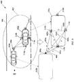
- FIG. 4 illustrates an exemplary computation of a position of a nearby vehicle with respect to the first vehicle 102a, in accordance with an embodiment of the disclosure.
- FIG. 4 is explained in conjunction with elements from FIGs.1 , 2 , and 3 .
- an exemplary top view 400 that depicts an area 402 of the road portion 306.
- the area 402 of the road portion 306 may include a certain portion of the first lane 302 of FIG. 3 including the first vehicle 102a and the second vehicle 102b.
- the audio-input devices 110a to 110d of the first vehicle 102a and the first sound beam 308a which corresponds to sound emanated from the second vehicle 102b.
- a block diagram of the first vehicle 102a and the second vehicle 102b is shown side-by-side to illustrate computation of position of the second vehicle 102b with respect to the first vehicle 102a in the area 402 of the road portion 306.
- the position of the second vehicle 102b with respect to the first vehicle 102a may be ascertained based on the first sound beam 308a emanated from the second vehicle 102b, and captured at the first vehicle 102a.
- first distance 404a a first distance 404a
- second distance 404b a third distance 404c (also represented as distances or sides "a”, “b”, and “c")
- third distance 404c also represented as distances or sides "a”, “b”, and “c”
- FIG. 4 illustrate pre-determined distances 408a, 408b, and 408c (also represented as “x”, “y” and “z”)among the audio-input devices110a, 110b, and 110c
- the pre-determined distances 408a, 408b, and 408c may be pair-wise distances between a pair of the audio-input devices 110a, 110b, and 110c, as shown.
- the pre-determined distances 408a, 408b, and 408c may be determined based on installation positions of the audio-input devices 110a to 110d in the first vehicle 102a.
- FIG. 5 illustrates a first exemplary pattern of traffic sound data captured from a nearby vehicle by the first vehicle 102a for determination of a relative position of the nearby vehicle with respect to the first vehicle 102a, in accordance with an embodiment of the disclosure.
- FIG. 5 is explained in conjunction with elements from FIGs.1 , 2 , 3 , and 4 .
- a sound signal pattern 500 associated with sound signals captured by the audio-input devices 110a to 110c from the second vehicle 102b (of FIG. 4 ).
- the sound signal pattern 500 shows capture of sound emanated from the second vehicle 102b of the one or more other vehicles.
- the sound signal pattern 500 may include sound signals associated with the first sound beam 308a that corresponds to the sound emanated from the second vehicle 102b ( FIG. 4 ).
- the sound signal pattern 500 is shown to include a first sound signal 502a, a second sound signal 502b, and a third sound signal 502c.
- Each of the three sound signals 502a to 502c may correspond to a sound channel that may be captured by an audio-input device from the audio-input devices 110a to 110c.
- each of the three sound signals 502a to 502c may correspond to the first sound beam 308a emanated from the second vehicle 102b.
- each of the three sound signals 502a to 502c may be emanated at the same time from the same sound source, that is, the second vehicle 102b.
- the audio-input devices 110a to 110d may receive sound emanated from the one or more other vehicles, such as the second vehicle 102b, that travel on the road portion 306. As shown in FIG. 4 , the second vehicle 102b may lie behind the first vehicle 102a in the first lane 302 of the road portion 306. The audio-input devices 110a, 110b, and 110c may capture the sound emanated from the second vehicle 102b, such as the first sound beam 308a. Now referring back to FIG. 5 , the first sound signal 502a may correspond to the first distance 404a (also represented as "a") between the second vehicle 102b and the audio-input device 110b (at the left side of the first vehicle 102a).
- the second sound signal 502b may correspond to the second distance 404b (also represented as “b") between the second vehicle 102b and the audio-input device 110c (at the right side of the first vehicle 102a). Further, the third sound signal 502c may correspond to the third distance 404c (also represented as “c") between the second vehicle 102b and the audio-input device 110a (at the rear end of the first vehicle 102a).
- the first sound signal 502a may arrive ahead of the other sound signals at the first vehicle 102a captured by the audio-input device 110a, due to the positioning of the audio-input devices 110a around the first vehicle 102a.
- the first sound signal 502a may be followed by the third sound signal 502c and then the second sound signal 502b, as shown.
- a time of arrival of a sound signal at the first vehicle 102a may be inversely proportional to a distance of the second vehicle 102b from respective audio-input device of the first vehicle 102a that captures the sound signal. For instance, referring back to FIG.
- the second distance 404b (such as "b") between the second vehicle 102b and the audio-input device 110c, may be greater than the first distance 404a and third distance 404c respectively (such as “a” and "c"). Accordingly, the second sound signal 502b, which may correspond to the second distance404b, may reach the first vehicle 102a after both the first sound signal 502a and the third sound signal 502c may have reached the first vehicle 102a. Further, the first sound signal 502a may arrive ahead of the third sound signal 502c, in case the first distance 404a is less than the third distance 404c, and vice versa.
- the ECU 108 may determine a relative distance of a same sound beam, such as the first sound beam 308a in this case, emanated from the second vehicle 102b, as received by the audio input devices 110a, 110b, and 110c, of the first vehicle 102a.
- the ECU 108 may determine a difference among relative distances of the second vehicle 102b from the audio input device 110b (the first distance 404a), the audio input device110c (the second distance 404b), and the audio input device 110a (the third distance 404c).
- the ECU 108 may determine a difference between relative times of arrival of the three sound signals 502a to 502c at the first vehicle 102a.
- the ECU 108 may determine a direction associated with a position of the second vehicle 102b with respect to the first vehicle 102a based on amplitude and/or direction of emission of each of the three sound signals 502a to 502c. Thereafter, the ECU 108 may determine the first distance 404a, the second distance 404b, and the third distance 404c (represented by "a", "b", and "c") by application of a time difference of arrival (TDOA) technique and/or a triangulation technique. Further, the ECU 108 may determine a shortest distance between the second vehicle 102b and the first vehicle 102a based on the determined first distance 404a, the second distance 404b, and the third distance 404c. The shortest distance between the second vehicle 102b and the first vehicle 102a may correspond to a perpendicular distance between a front end of the second vehicle 102b and a rear end of the first vehicle 102a.
- TDOA time difference of arrival
- the ECU 108 may further use the one or more ultrasonic sensors associated with the sensing system 220 of the first vehicle 102a to re-estimate the determined perpendicular distance between the first vehicle 102a and the second vehicle 102b.
- the ECU 108 may re-estimate the perpendicular distance between the first vehicle 102a and the second vehicle 102b to improve the accuracy of the previously determined perpendicular distance.
- the one or more ultrasonic sensors under the command of the ECU 108, may transmit one or more electromagnetic signals (such as ultrasonic waves) towards the determined direction of the second vehicle 102b.
- the one or more ultrasonic sensors may receive back one or more reflected electromagnetic signals (such as reflected ultrasonic waves) from the second vehicle 102b. Based on a time elapsed between the transmission of the one or more electromagnetic signals and the receipt of the one or more reflected electromagnetic signals, the ECU 108 may re-estimate the perpendicular distance between the second vehicle 102b and the first vehicle 102a. The ECU 108 may also re-estimate the first distance 404a, the second distance 404b, and the third distance 404c, in a manner similar to the re-estimation of the perpendicular distance. The one or more electromagnetic signals may be transmitted in directions associated with the respective distances from the first vehicle 102a to the second vehicle 102b.
- the ECU 108 may determine speed of the one or more other vehicles (such as the second vehicle 102b, the third vehicle 102c, and the fourth vehicle 102d) based on the sound data captured from the respective vehicles. Further, the ECU 108 may determine the relative velocity of the second vehicle 102b with respect to the first vehicle 102a, based on the sound data captured from the second vehicle 102b. For example, difference in the amplitude or pitch of the sound signals captured by the audio-input devices 110a, 110b, and 110c, and/or the determined TDOA may be utilized for the determination of speed and/or the relative velocity. Alternatively, the ultrasonic sensors (when present) may further be used for determination of the speed and/or relative velocity, when the speed of the first vehicle 102a is known (based on an instantaneous speedometer reading).
- the ECU 108 may be further configured to calculate the angle 406 (represented by angle "A") at which the second vehicle 102b is positioned with respect to the audio-input devices 110b (at the left side) and the audio-input device 110c (at the right side) of the first vehicle 102a. That is, the angle 406 (represented by angle “A”) may correspond to the angle formed between the lines that corresponds to the first distance 404a and the second distance 404b (represented by sides “a” and "b") of the triangle "bay”.
- the ECU 108 may perform a beam-forming procedure by transmission of directed sound beams towards the detected second vehicle 102b based on the calculated angle 406.
- the transmitted directed sound beams may be reflected from the second vehicle 102b.
- the reflected sound beams may be captured by the two or more audio capture devices 110.
- the ECU 108 may estimate the relative distance between the first vehicle 102a and the second vehicle 102b. An exemplary embodiment of the beam-forming procedure is explained in conjunction with FIG. 8 .
- the determined relative distance and angle information of the second vehicle 102b with respect to the first vehicle 102a when obtained, may be used by the ECU 108 to generate the virtual sound for the second vehicle 102b.
- the ECU 108 may convert the determined distance and angle of the second vehicle 102b with respect to the first vehicle 102a, from a Euclidean coordinate system to a spherical coordinate system.
- the distance and angle information may be used to apply a head-related transfer function (HRTF).
- HRTF head-related transfer function
- the ECU 108 may apply one or more sound filters on the first sound beam 308a, which may be captured by the audio-input devices 110a to 110c as constituent signals of the sound signal pattern 500. Based on the application of the one or more sound filters, the ECU 108 may determine a sound signature associated with the second vehicle 102b. The ECU 108 may then compare the determined sound signature of the second vehicle 102b with pre-stored sound signatures in the memory 204. The pre-stored sound signatures may correspond to vehicles and objects of various types. Examples of types of the vehicles may include, but not limited to, four wheelers, three wheelers, two wheelers, trucks, cars, SUVs, and/or multi-utility vehicles. Objects other than vehicles may include, but not limited to, humans, animals, and/or other sound producing objects. Based on the comparison, the ECU 108 may determine the type of the second vehicle 102b.
- the virtual sound associated with the second vehicle 102b may be generated based on the determined type of the second vehicle 102b.
- the pitch and frequency of the virtual sound output in the first vehicle 102a may be based on the determined type of the second vehicle 102b.
- Pitch and frequency values to be used for generation of the virtual sound output for vehicles and objects of various types may be stored along with the sound signatures in the memory 204.
- the ECU 108 may extract the pitch and frequency values of the vehicle type determined for the second vehicle 102b from the memory 204.
- the ECU 108 may accordingly generate the virtual sound output of the relevant pitch and frequency value(s) extracted from the memory 204 for the second vehicle 102b.
- the resultant virtual sound output may enable the driver 114 to easily understand where to focus to drive safely in a crowded traffic area along the road portion (such as the road portion 306 or the road portion 118).
- the ECU 108 may also determine one or more driving parameters associated with the second vehicle 102b. For instance, the ECU 108 may determine a currently applied engine gear by the second vehicle 102b, based on the application of the one or more sound filters. The pitch and/or frequency of the virtual sound output may also be based on the currently applied gear by the second vehicle 102b, as determined by the ECU 108. In accordance with an embodiment, an amplitude value of the virtual sound output may be proportional to the distance and/or relative velocity of the second vehicle 102b from the first vehicle 102a.
- the virtual sound output associated with the second vehicle 102b may include a pre-recorded audio track associated with a vehicle type of the second vehicle 102b.
- the virtual sound output may include at least a recorded portion of the sound captured from the second vehicle 102b, in real-time or near real-time.
- the in-vehicle alert including the virtual sound of the second vehicle 102b may then be reproduced through the second set of audio-output devices 228a and 228d or the first set of audio output devices 226a and 226b.
- FIG. 6 illustrates a second exemplary top view of a road portion that depicts capture of traffic sound emanated from vehicles in vicinity of a first vehicle, in accordance with an embodiment of the disclosure.
- FIG. 6 is explained in conjunction with FIGs. 1 and 2 .
- a top view 600 of a road portion 606 that may include a first lane 602 and a second lane 604. Multiple vehicles are shown to traverse the road portion 606 such as the first vehicle 102a, a car 608a, a trailer 608b, a truck 608c, a bike 608d, a bike 608e, and a car 608f.
- the car 608a and the trailer 608b are shown to traverse along the first lane 602, while the truck 608c, the bike 610d, the first vehicle 102a, the bike 608e, and the car 608f are shown to travel along the second lane 604 in opposite direction.
- the first vehicle 102a is shown to include the two or more audio-input devices such as 110a to 110h. Further, a first set of sound beams 610a, a second set of sound beams 610b, and a third set of sound beams 610c are shown as being respectively emanated from the truck 608c, the bike 608d, and the car 608a, towards the first vehicle 102a.
- the audio-input devices 110e, 110a, and 110f are shown as installed at the back-left, back, and back-right end of the first vehicle 102a.
- Each of the aforementioned three audio-input devices 110e, 110a, and 110f may capture individual directed sound beams within the first set of sound beams 610a, the second set of sound beams 610b, and the third set of sound beams 610c.
- the first set of sound beams 610a may include three directed sound beams.
- a first of the three sound beams may be directed towards the back-left end of the first vehicle 102a and thus may be captured by the audio-input device 110e that is installed at the back-left end of the first vehicle 102a.
- a second and a third of the three sound beams may be directed towards the back-center end and the back-right end of the first vehicle 102a.
- the second sound beam of the first set of sound beams 610a may be captured by the audio-input device 110a (at back end), while the third sound beam of the first set of sound beams may be captured by the audio-input device 110f (at back-right end).
- FIG. 7 illustrates a second exemplary pattern of traffic sound data captured from one or more nearby vehicles by a first vehicle for determination of relative position of a nearby vehicle with respect to the first vehicle, in accordance with an embodiment of the disclosure.
- FIG. 7 is explained in conjunction with FIGs. 1 , 2 , and 6 .
- a first signal stream 702a there is shown a first signal stream 702a, a second signal stream 702b, and a third signal stream 702c.
- a set of first vehicle-type signals 704a to 704c there is shown a set of second vehicle-type signals 706a to 706c, and a set of third vehicle-type signals 708a to 708c.
- the first signal stream 702a may correspond to the audio signals captured by the audio-input device 110e, installed at the back-left end of the first vehicle 102a, as shown in FIG. 7 .
- the second signal stream 702b and the third signal stream 702c may correspond to the audio signals captured by the audio-input devices 110a and 110f, which are installed at the back-center and the back-right end of the first vehicle 102a.
- the set of first vehicle-type signals 704a to 704c is considered to include the first set of sound beams 610a captured from the truck 608c.
- the set of second vehicle-type signals 706a to 706c are considered to include the second set of sound beams 610b captured from the car 608a and the bike 608d.
- the set of third vehicle-type signals 708a to 708c are considered to include the third set of sound beams 610c captured from the bike 608d.
- the ECU 108 may identify a signal stream that includes the earliest occurrence of vehicle-type signals. That is, the ECU 108 may check as to which of the audio-input devices first captured a sound beam emanated from a nearby vehicle. For instance, as shown in FIG. 7 , the second signal stream 702b corresponding to the back-center audio input device 110a received the earliest vehicle-type signals (that is, signals 704b from the first set of sound beams 610a). Thereafter, the ECU 108 may correlate the other signals of the same vehicle-type received at the other audio-input devices.
- signals 704a and 704c of the first vehicle-type may be correlated with the signals 704b (the earliest received signals), as these are captured from the same vehicle (i.e., the truck 608c).
- the start position of the signals received from that vehicle at the other audio-input devices may be identified. For instance, the start positions of the reception of the signals of the truck 608c in the first signal stream 702a and the third signal stream 702c may be identified based on the correlation of the set of first vehicle-type signals 704a to 704c. Further, based on the identification of the start positions, signal delays may be determined. For instance, the delay of the signals 704a and 704c with respect to each other and with respect to the signals 704b may be determined. Based on the determined delays, a relative angle of approach of the identified nearest vehicle (e.g., the truck 608c) with respect to the first vehicle 102a may be determined.
- the identified nearest vehicle e.g., the truck 608c
- the relative angle of the first vehicle 102a with respect to the other nearby vehicles may also be determined.
- An alternate embodiment of the determination of the relative angle of the nearest vehicles is explained in FIG. 4 .
- the ECU 108 may perform a beam-forming based determination of the relative position of the nearest identified vehicle (e.g., the truck 608c). The beam-forming may be performed along the determined relative angle of approach of the nearest vehicle (e.g., the truck 608c) with respect to the first vehicle 102a. An exemplary beam-forming procedure is explained further in conjunction with FIG. 8 .
- FIG. 8 illustrates an exemplary beam forming procedure performed by a first vehicle to ascertain relative position of a nearby vehicle with respect to the first vehicle, in accordance with an embodiment of the disclosure.
- FIG 8 is explained in conjunction with elements from FIGs 1 , 2 , 6 and 7 .
- a top view 800 of the road portion 606 that may include the first lane 602 and the second lane 604, as also shown in FIG. 6 .
- the car 608a and the trailer 608b are shown to travel in the first lane 602
- the truck 608c, the bike 608d, the first vehicle 102a, the bike 608e and the car 608f are shown to traverse the second lane 604.
- vehicles in the first lane 602 travel in the opposite direction with reference to vehicles in the second lane 604.
- the first vehicle 102a is shown to include the two or more audio-input devices 110a to 110h.
- the audio-input devices 110e, 110a, and 110f may be installed at back-right, back-center, and back-left end of the first vehicle 102a to capture sound beams emanated from the nearby vehicles.
- the nearby vehicles such as the car 608a, the truck 608c, and the bike 608d, may emanate sound beams towards the audio-input devices 110e, 110a, and 110f.
- the car 608a, the truck 608c, and the bike 608d may emanate the first set of sound beams 610a, the second set of sound beams 610b, and the third set of sound beams 610c, as shown in FIG. 8 .
- An exemplary embodiment of the analysis of the patterns of sound beams captured from the nearby vehicles is explained in conjunction with FIG. 7 .
- the nearest vehicle e.g., the truck 608c
- the relative angle of approach of the nearest vehicle with respect to the first vehicle 102a may be determined, as explained in conjunction with FIG. 7 .
- the ECU 108 may perform beam-forming along the determined relative angle of approach of the nearest vehicle (e.g., the truck 608c).
- the beam-forming may be performed by projecting directed beams (e.g., directed sound beams or directed millimeter-wave radio beams) towards the determined relative angle of approach of the nearest vehicle (e.g., the truck 608c) by the first vehicle 102a.
- the audio-input devices 110e, 110a, and 110f of the first vehicle 102a may receive beams that bounce-back or reflect from the nearest vehicle (e.g., the truck 608c).
- the ECU 108 may determine the relative position of the nearest vehicle (e.g., the truck 608c) from the first vehicle 102a. Beam-forming performed with respect to the truck 608c has been depicted in FIG. 8 by the rays 802.
- FIGs. 9A and 9B illustrate two exemplary top views of an interior of the first vehicle 102a that depict reproduction of virtual sound of the second vehicle 102b or other objects in a traffic area, in accordance with an embodiment of the disclosure.
- FIGs. 9A and 9B are explained in conjunction with elements from FIGs. 1 to 8 .
- a first top view 900A of an interior of the first vehicle 102a is shown to include a first sound field 902, a driver seat 904, one or more co-passenger seats 906a to 906c, a steering wheel 216a, and the ECU 108.
- FIG. 9A further shows the display screen 210.
- the ECU 108 may be configured to determine the distance between the first vehicle 102a and at least the second vehicle 102b, based on the determined position and angle of the second vehicle 102b from the first vehicle 102a. The distance may be determined based on received sound data that corresponds to sound emanated from other vehicles including at least the second vehicle 102b and objects in the traffic area of the first vehicle 102a. The determination of the distance between the first vehicle 102a and the second vehicle 102b is explained in FIGs. 4 and 5 (refer expression 1). Further, the ECU 108 may apply the HRTF (refer expression 2) to generate the virtual sound of the second vehicle 102b, as an in-vehicle alert, through one or more sound reproduction devices in the first vehicle 102a. The virtual sound may be reproduced at one or more locations within the first vehicle 102a to control or create sound fields for the driver 114 or both the driver 114 and the co-passenger(s), as explained below.
- the second set of audio-output devices 228a to 228d may reproduce the virtual sound output of the in-vehicle alert generated by the ECU 108 to all the passengers of the first vehicle 102a.
- the each audio-output device in the second set of audio-output devices 228a to 228d may contribute to creation of the virtual sound output represented by the first sound field 902.
- the second set of audio-output devices 228a to 228d may be installed at four corners of the first vehicle 102a.
- the audio-output devices 228a and 228b may be installed at the rear corners of the first vehicle 102a to reproduce sound for passengers seated at the rear passenger seats 906b and 906c, respectively.
- the audio-output devices 228c and 228d may be installed at the front corners of the first vehicle 102a to reproduce sound for a front co-passenger seated at the seat 906a and the driver 114 seated at the driver seat 904.
- the first sound field 902 created by second set of audio-output devices 228a to 228d may be audible to the driver 114 seated at the driver seat 904 and the co-passengers seated at the co-passenger seats 906a to 906c.
- the in-vehicle alert may be reproduced through the first sound field 902 based on a traffic condition of the traffic area associated with the first vehicle 102a. For instance, in case of an accident warning or where another vehicle is approaching at high speed towards (or is within a predetermined proximity to) the first vehicle 102a, the in-vehicle alert may be reproduced through the first sound field 902 for all the passengers. Further, the in-vehicle alert may be reproduced as the first sound field 902 in certain driving conditions such as at night, during fog, and/or rush hours. During normal driving conditions, the in-vehicle alert may be generated only for the driver 114 as explained in FIG. 9B , without disturbing other co-passengers in the first vehicle 102a.
- a second top view 900B of an interior of the first vehicle 102a is shown to include a second sound field 908a, a third sound field 908b, the driver seat 904, the one or more co-passenger seats 906a to 906c, the steering wheel 216a, and the ECU 108. Further, FIG. 9B illustrates the first set of audio-output devices 226a and 226b, the second set of audio-output devices 228a to 228d, and the display screen 210.
- the in-vehicle alert which may include the virtual sound representative of sound emanated from the second vehicle 102b, may be reproduced only for the driver 114 of the first vehicle 102a, to assist the driver 114.
- the co-passengers of the first vehicle 102a may not be provided with the in-vehicle alert and may either hear no sound or may listen to music played out through a music system (or the infotainment system 208) of the first vehicle 102a. That is, the co-passengers may not be disturbed with in-vehicle alerts and may continue to enjoy music or may not hear sound at all. This may be the case in normal driving conditions, where sufficient distance is maintained between the vehicles, traffic rules are followed, and/or there is no eminent threat, or obstacle.
- the first set of audio-output devices 226a and 226b may reproduce the in-vehicle alert directed towards the driver 114 seated at the driver seat 904. As shown in FIG. 9B , each of the first set of audio-output devices 226a and 226b may contribute to creation of the second sound field 908a directed towards the driver 114.
- the first set of audio-output devices 226a and 226b may be installed on or around the driver seat 904 to provide a binaural sound output to the driver 114.
- the binaural sound output may correspond to the second sound field 908a including the virtual sound output of the in-vehicle alert.
- the one or more co-passengers of the first vehicle 102a may be provided a separate sound output, such as the third sound field 908b.
- the third sound field 908b may include a music track or infotainment channel reproduced for the one or more co-passengers by use of a music system or the infotainment system 208 of the first vehicle 102a.
- the ECU 108 by use of the one or more audio-output devices of the second set of audio-output devices 228a to 228d may control or create the third sound field 908b for the co-passengers of the first vehicle 102a.
- the audio output devices 228a to 228c may reproduce the third sound field 908b for the co-passengers seated at the seats 906b, 906c, and 906a, respectively.
- the third sound field 908b may not be reproduced and the co-passengers may not hear any sound at all.
- the reproduction of sound fields within the interior of the first vehicle 102a may switch automatically based on an assessment of a traffic condition by the ECU 108. For instance, the ECU 108 may continue to determine distances of the one or more other vehicles from the first vehicle 102a. Based on a change in traffic condition, such as the detection of a speeding vehicle approaching the first vehicle 102a, the ECU 108 may switch to generation of the first sound field 902 (of FIG. 9A ). In accordance with an embodiment, the ECU 108 may also switch to generation of the first sound field 902 when a specific type of vehicle (such as a truck or a long trailer) is within the pre-determined proximity of the first vehicle 102a. However, in normal driving conditions, the ECU 108 may continue to generate the second sound field 908a and/or the third sound field 908b (in case the infotainment system 208 is in use by the co-passengers) of FIG. 9B .
- a specific type of vehicle such as a truck or a long trailer
- preferences to create a particular sound field (from the first sound field 902 and the second sound field 908a) to reproduce the in-vehicle alert may be customizable by the driver 114 and/or the co-passengers of the first vehicle 102a, via an interface, such as the display screen 210 or via the infotainment system 208.
- the ECU 108 may generate in-vehicle alerts based on the determined distances of the other vehicles that lie within a pre-determined proximity from the first vehicle 102a.
- the generated in-vehicle alerts may include virtual sounds that may represent sound emanated from the particular vehicles that currently lie within the predetermined proximity from the first vehicle 102a.
- the generated in-vehicle alerts may also include a combination of two or more virtual sound outputs based on the determined distances of the other vehicles. The reproduction of each such virtual sound output may depend on the type of the respective vehicle.
- the virtual sound outputs of distinct vehicles may seem distinctly identifiable by the driver 114 such that the driver 114 may assess the type of the vehicle, proximity, or speed, and drive accordingly.
- an indication of the other vehicles in the predetermined proximity of the first vehicle 102a may be displayed through the display screen 210.
- a user such as the driver 114 or a passenger may be able to track the movement of the other vehicles on a map based on the indication displayed through the display screen 210.
- the ECU 108 may determine a relative velocity (with respect to the first vehicle 102a) of the one or more other vehicles in the plurality of vehicles 102 including at least the second vehicle 102b.
- the determination of the relative velocity of another vehicle, such as the second vehicle 102b may also be based on the captured sound emanated from that vehicle and the associated distance determined therefrom, as explained above in FIGs. 4 and 5 .
- the ECU 108 may generate an audio warning. The audio warning may be included within the in-vehicle alert.
- the audio warning may be generated along with the in-vehicle alert.
- the driver 114 may then become aware of the speeding vehicle.
- the audio warning may be reproduced through the first sound field 902.
- the in-vehicle alert may be switched from the second sound field 908a to the first sound field 902, if not already so.
- the audio warning may be reproduced only to the driver 114 through the second sound field 908a irrespective of current use of the first sound field 902 for reproduction of the in-vehicle alert.
- the audio warning may be exclusively provided to the driver 114.
- the sound emanated from the second vehicle 102b may be captured as a direct sound beam at the first vehicle 102a. This may be the case when the second vehicle 102b may be within a line-of-sight (LOS) associated with the first vehicle 102a. However, in case the second vehicle 102b is not in a direct LOS of the first vehicle 102a, the sound emanated from the second vehicle 102b may be captured as an indirect or reflected (multi-path) sound beam at the first vehicle 102a.
- the ECU 108 may still determine the distance between the first vehicle 102a and the second vehicle 102b by use of the TDOA and/or triangulation techniques, based on the captured indirect sound of the second vehicle 102b, as explained above.
- the second vehicle 102b may be detected and located. Further, the ECU 108 may generate the in-vehicle alert for the driver 114, based on a predetermined proximity and/or relative velocity of the second vehicle 102b with respect to the first vehicle 102a.In a case when multiple vehicles are present within the pre-determined proximity of the first vehicle 102a and/or one or more others vehicle approach the first vehicle 102a with a high relative velocity, the ECU 108 may generate appropriate virtual sounds and/or alerts messages as part of the in-vehicle alert.
- Each of the virtual sound outputs may be specific to the specific detected vehicles, based on the type of the respective vehicles, their respective distances, and/or relative velocities with respect to the first vehicle 102a.
- the driver 114 may be able to distinctly identify the various vehicles around the first vehicle 102a in the current driving scenario and appropriately maneuver the first vehicle 102a.
- the ECU 108 may be further configured to communicate statistical data of the traffic condition in the traffic area to a remote control center at a second location, such as a traffic monitoring center, for traffic management and control.
- a remote control center at a second location, such as a traffic monitoring center, for traffic management and control.
- the ECU 108 may transmit the statistical data in real time or periodically to the cloud server 104, via the wireless communication network 106.
- the transmission of the statistical data to the cloud server 104 may be via the RSU 120 installed along the road portion 118 (of FIG. 1 ).
- the ECU 108 may transmit the statistical data directly to the cloud server 104.
- the cloud server 104 may be configured to compile such statistical data received from the plurality of vehicles 102 and analyze trends associated with the traffic condition in the traffic area over a period of time. Further, the compiled data may be used for analysis of accidents and driving behavior of the public at large.
- the ECU 108 may also transmit the statistical data to an electronic device of a user of the first vehicle 102a, such as the driver 114. Examples of the electronic device may include, but not limited to, a smartphone, a laptop, a personal computer, a tablet computer, a wearable device, and/or an Internet-of-Things (IoT) device that may be connected to a vehicle network.
- IoT Internet-of-Things
- Example of the statistical data may include, but not limited to, distance of the second vehicle 102b from the first vehicle 102a, a relative velocity of the second vehicle 102b with respect to the first vehicle 102a, and/or the type of the second vehicle 102b.
- the statistical data may further include a count of the one or more other vehicles within a pre-determined distance (or pre-determined proximity) from the first vehicle 102a, and the generated in-vehicle alerts.
- the cloud server 104 may use the statistical data, related to the traffic condition, received from the ECU 108 of the first vehicle 102a for other non-transportation implementations. For instance, multiple vehicles including the plurality of vehicles 102, may implement the ECU 108, in a manner similar to the first vehicle 102a. The cloud server 104 may receive such traffic condition related statistical data from the multiple vehicles (such as the plurality of vehicles 102) for a period of time. The cloud server 104 may also receive corresponding virtual sound output generated by the multiple vehicles (such as the plurality of vehicles 102) during a pre-defined period of time. The cloud server 104 may use the received statistical data related to the traffic conditions and the received corresponding virtual sound outputs to generate metadata associated with a particular road portion and set of vehicles (such as the plurality of vehicles 102).
- the cloud server 104 may use the generated metadata in various application scenarios, such as virtual reality, augmented reality, gaming, driver training, control of autonomous vehicles, and/or training or enhancement of machine learning algorithms used for driving of autonomous vehicles.
- the ECU 108 may further be configured to display a representation of the second vehicle 102b and/or one or more objects in the traffic area of the first vehicle 102a, via the display screen 210.
- the display screen 210 may be associated with the infotainment system 208 of the first vehicle 102a.
- the display screen 210 may further display the statistical data of the traffic condition in the vicinity of the first vehicle 102a, which may also be transmitted to the cloud server 104, via the wireless communication system 206.
- the display screen 210 may illustrate virtual objects to represent the second vehicle 102b, the one or more objects, and/or the statistical data on a map associated with the traffic area.
- the image-capturing devices 112a to 112b may capture one or more images of the second vehicle 102b and the one or more objects.
- the display of the virtual objects on the display screen 210 may be controlled based on the recognition the one or more objects from the one or more images and the determined distances from the first vehicle 102a.
- the ECU 108 may generate audio and/or visual information that may assist the driver 114 to drive correctly on the road portion 306.
- FIG. 10 illustrates a first exemplary traffic scenario to process traffic sound data to provide in-vehicle driver assistance, in accordance with an embodiment of the disclosure.
- FIG. 10 is explained with reference to elements from FIGs.1 to 8 , 9A, and 9B .
- FIG. 10 there is shown a top view of a first exemplary traffic scenario 1000.
- the first exemplary traffic scenario 1000 may include a first lane 1002 and a second lane 1004 in a road portion 1012.
- the first exemplary traffic scenario 1000 further include vehicles that travel along the road portion 1012 on the first lane 1002 or the second lane 1004.
- the vehicles in the first lane 1002 include the first vehicle 102a (such as a first car), a second car 1006a, a third car 1006b, a fourth car 1006c, and a fifth car 1006d. Further, the vehicles in the second lane 1004 include a sixth car 1006e, a truck 1008, and a trailer 1010. All the vehicles, including the first vehicle 102a, are shown to move in a forward direction, denoted by the arrow, on the first lane 1002 and the second lane 1004.
- the first vehicle 102a may be following driving rules, in the current scenario. Further, the driving conditions may also be normal in the first exemplary traffic scenario 1000.
- the ECU 108 may determine the distance and relative velocity of the first vehicle 102a with respect to the other vehicles that travel along the road portion 1012, based on a capture of sound emanated from the other vehicles. Based on the distance (and/or the relative velocity), the ECU 108 may determine the current traffic condition as a normal driving condition, as explained in the aforementioned. Hence, the in-vehicle alert may be reproduced by the first set of audio-output devices 226a and 226b in the second sound field 908a, thereby providing the in-vehicle alert only to the driver 114 of the first vehicle 102a.
- the ECU 108 may continuously generate a pleasant sound (such as a music track or pre-defined tune) in the in-vehicle alert in a normal driving condition and/or when the traffic rules are followed.
- the display screen 210 may display a virtual representation of the second car 1006a, the third car 1006b, and the fourth car 1006c, as these may correspond to the vehicles that may lie within the predetermined distance from the first vehicle 102a.
- the ECU 108 may display that captured image of the vehicle on the map on the display screen 210, using the infotainment system 208.
- FIG. 11 illustrates a second exemplary traffic scenario to process traffic sound data to provide in-vehicle driver assistance, in accordance with an embodiment of the disclosure.
- FIG. 11 is explained with reference to elements from FIGs.1 to 8 , 9A , 9B , and 10 .
- FIG. 11 there is shown a top view of a second exemplary traffic scenario 1100.
- the second exemplary traffic scenario 1100 may include a first lane 1102 and a second lane 1104 of a road portion 1106.
- the second exemplary traffic scenario 1100 further includes vehicles that travel along the road portion 1106 on the first lane 1102 or the second lane 1104.
- the vehicles in the first lane 1102 may include the second car 1006a, the third car 1006b, the fourth car 1006c, the fifth car 1006d, and the sixth car 1006e. Further, the vehicles in the second lane 1104 may include the first vehicle 102a (such as the first car), a seventh car 1006f, an eight car 1006g, and a ninth car 1006h.
- All the vehicles except the first vehicle 102a are shown to move in a forward direction, in their respective lanes, on the road portion 1106.
- the first vehicle 102a is shown to change its lane from the second lane 1104 towards the first lane 1102, as depicted by a dashed arrow in FIG. 11 .
- both the first lane 1102 and the second lane 1104 may be crowded with vehicles. Hence, overtaking other vehicles in such a traffic condition may not be recommended for safe driving. Further, a safe distance may be required to be maintained between the first vehicle 102a and the other vehicles that travel along the road portion 1106.
- the ECU 108 may detect that the first vehicle 102a is changing lanes based on in-vehicle data extracted from the in-vehicle network 222 or one or more images captured by one or more of the image-capturing devices 112a to 112b.
- the audio-input devices 110a to 110h of the first vehicle 102a may capture sound emanated from various vehicles in the road portion 1106.
- the ECU 108 may determine that the first vehicle 102a may lie within close proximity to one or more other vehicles that the first vehicle 102a may overtake (or may have overtaken).
- the ECU 108 may determine if the first vehicle 102a is overtaking other vehicles from a "wrong-side", which may be against the traffic rules.
- the seventh car 1006f may lie in close proximity to the first vehicle 102a.
- the first vehicle 102a may have overtaken past the seventh car 1006f from a "wrong-side", such as a left side. Further, the first vehicle 102a may begin to change its lane from the second Iane1104 to the first lane 1102, as shown in FIG. 11 .
- the ECU 108 may generate an audio warning associated with the close proximity to seventh car 1006f, in a manner similar to that discussed in FIG. 9B .
- the audio warning may be indicative of the wrongful overtaking and/or changing of lanes by the driver of the first vehicle 102a.
- the ECU 108 may determine that the lane change may cause traffic blockage. Hence, the ECU 108 may again generate an audio warning indicating a potential traffic blockage situation due to the lane change.
- the audio warning may be reproduced in the second sound field 908a directed exclusively towards the driver 114 of the first vehicle 102a.
- the audio warning may be included in the in-vehicle alert.
- the audio warning may include recorded messages indicative of the traffic condition and/or incorrect driving by the driver of the first vehicle 102a.
- the audio warning may also include an unpleasant sound, such as an alarm, a hoot, a horn, a chime, or a bell, which may attract attention for immediate action by the driver 114.
- the audio warning may continue to be reproduced along with the in-vehicle alert until the driver 114 corrects a driving course of the first vehicle 102a.
- the ECU 108 may assess the current traffic condition of the road portion 1106, based on the determination of distance and/or relative velocity of other vehicles near the first vehicle 102a on the road portion 1106. Based on the current traffic condition, the ECU 108 may determine whether or not the first vehicle 102a should change lanes or overtake other vehicles. For instance, in case of a crowded (or dense) traffic condition, the ECU 108 may determine that the first vehicle 102a should not change lanes or overtake other vehicles. In addition, the ECU 108 may assess various adverse driving conditions associated with the road portion 1106 such as rain, poor light, night time, snow, fog, dust/hail storm, or traffic blockage (such as due to rush hour, or pedestrian rush).
- adverse driving conditions associated with the road portion 1106 such as rain, poor light, night time, snow, fog, dust/hail storm, or traffic blockage (such as due to rush hour, or pedestrian rush).
- the ECU 108 may receive information associated with weather and driving conditions associated with a location around the road portion 1106 from the infotainment system 208.
- the infotainment system 208 may receive the aforementioned information from the cloud server 104, via one of the RSUs (such as the RSU 120) that may be positioned along the road portion 1106, over the wireless communication network 106.
- the ECU 108 may receive this information directly from the cloud server 104.
- the ECU 108 may assess whether the current driving condition corresponds to an adverse driving condition, as enumerated above.
- the weather conditions may also be analyzed by use images captured by one or more of the image-capturing devices 112a to 112b in the first vehicle 102a.
- the ECU 108 may generate distinct virtual sounds that may be reproduced by the first set of audio-output devices 226a and 226b for the driver 114.
- the driver 114 may then be instructed to reduce the speed of first vehicle 102a or take other suitable action.
- the distinct virtual sounds related to the weather condition may be reproduced by the second set of audio-output devices 228a to 228d for all the passengers of the first vehicle 102a.
- the ECU 108 may generate an in-vehicle alert that may be reproduced for all the passengers of the first vehicle through the first sound field 902a, in case of an adverse driving condition.
- the in-vehicle alert may include an instruction to avoid overtaking and changing lanes.
- the in-vehicle alert may include another instruction that may direct a reduction of speed of the first vehicle 102a such that a safe distance may be maintained from the other vehicles that travel on the road portion 1106.
- the ECU 108 may also display messages related to the in-vehicle alerts through the display screen 210.
- the messages may include the weather and driving condition information received from the cloud server 104, in addition to an indication of the assessed adverse driving condition.
- These messages may be displayed via the infotainment system 208 of the first vehicle 102a.
- the messages may also be displayed on an electronic device of a user of the first vehicle 102a, in case the electronic device (such as a smartphone or a wearable device) is communicatively coupled to the infotainment system 208.
- the image-capturing devices 112a to 112b may be activated based on an instruction by the ECU 108 or a press of a special button.
- a virtual distinct sound may be produced for the driver 114 to take action immediately.
- the image-capturing devices 112a to 112b may capture images from various angles or appropriate side to capture specific details related to the hitting vehicle, such as a number plate, driver's photo, and/or co-passenger's photo. This information related to specific details may be used by vehicle insurance companies to verify insurance claims or by law enforcement agencies as per need.
- FIG. 12 illustrates a third exemplary traffic scenario to process traffic sound data to provide in-vehicle driver assistance, in accordance with an embodiment of the disclosure.
- FIG. 12 is explained with reference to elements from FIGs.1 to 8 , 9A , 9B , 10 , and 11 .
- FIG. 12 there is shown a top view of a third exemplary traffic scenario 1200.
- the third exemplary traffic scenario 1200 may include a first lane 1202 and a second lane 1204 of a road portion 1206.
- the third exemplary traffic scenario 1200 further includes vehicles that travel along the road portion 1206 on the first lane 1202 or the second lane 1204.
- the vehicles in the first lane 1202 include the second car 1006a, the fourth car 1006c, and the fifth car 1006d. Further, the vehicles in the second lane 1204 include the first vehicle 102a (such as the first car), the third car 1006b, the sixth car 1006e, and the truck 1008.
- the first vehicle 102a all the vehicles except the first vehicle 102a, such as cars 1006a to 1006e and the truck 1008, are shown to move in their respective lanes without changing lanes.
- the first vehicle 102a is shown to its change lane from the second lane 1204 to the first lane 1202.
- the current traffic condition may correspond to a moderate traffic level.
- a safe driving distance may be maintained between the first vehicle 102a and the other vehicles that travel along the road portion 1206.
- a gap between the second car 1006a and the third car 1006b, which lie in front of the first vehicle 102a on the road portion 1206, may be sufficient to accommodate the first vehicle 102a.
- the first vehicle 102a may be safely maneuvered between the second car 1006a and the third car 1006b, once the first vehicle 102a changes its lane to the first lane 1202.
- the first vehicle 102a may be following driving rules, in this case.
- the driving or weather conditions may also be normal in the current scenario.
- the ECU 108 may determine the distance and/or relative velocity of other vehicles near the first vehicle 102a on the road portion 1206, as described above in FIGs. 4 , 5 , 6 , 7 and 8 .
- the ECU 108 may generate in-vehicle alert for the driver 114 of the first vehicle 102a.
- the in-vehicle alert may be reproduced by the first set of audio-output devices 226a and 226b in the second sound field 908a, to provide audio associated with the in-vehicle alert exclusively to the driver 114 of the first vehicle 102a.
- the display screen 210 may display a virtual representation of the second car 1006a and the third car 1006b, as these may correspond to the vehicles that may lie within the predetermined distance from the first vehicle 102a.
- the display screen 210 may display a message that may recommend lane-change and guide the driver to maintain a particular speed and distance from the nearby vehicles (such as the second car 1006a and the third car 1006b).
- the ECU 108 may be configured to transmit the in-vehicle alert and/or audio warnings generated in the first vehicle 102a to one or more other vehicles that may be within a pre-determined proximity to the first vehicle 102a.
- the transmission may occur via a V2V networking infrastructure.
- the transmission may be via the wireless communication network 106, through one of the RSUs (not shown in FIG. 12 ) installed on the road portion 1206.
- the in-vehicle alert and/or audio warning generated in the first vehicle 102a may be emanated as a directed sound beam towards a vehicle within pre-determined proximity of the first vehicle 102a by ECU 108.
- an appropriate audio message may be transmitted via a V2V communication to a desired vehicle or a directed sound beam may be beamed to the desired vehicle as an indication of overtake or change of lane.
- the first vehicle 102a may correspond to an autonomous vehicle, a semi-autonomous vehicle, or a non-autonomous vehicle.
- the ECU 108 may monitor the distance and relative velocity between the other vehicles and the first vehicle 102a. The distance and the relative velocity of the other vehicles may be determined based on sound emanated from these vehicles (such as the cars 1006a to 1006e and the truck 1008), captured by the two or more audio-input devices 110a to 110d. The determination of the distance and the relative velocity is explained in FIGs. 4 , 5 , 6 , 7 , and 8 .
- the ECU 108 may control an automatic drive of the first vehicle 102a on the road portion 1206. Accordingly, the ECU 108 may issue instructions to the powertrain control system 214 including the steering system 216 and/or the braking system 218 to control a steering direction and/or velocity of first vehicle 102a along the road portion 1206. The instructions may be issued via the in-vehicle network 222. Further, the ECU 108 may also issue instructions indicative of a lane change command or an overtake command, based on the determined distances and/or relative velocity when the sound data is received and processed (as explained in FIGs. 4 , 5 , 6 , 7 , and 8 ).
- the issued instructions may also be sent to the powertrain control system 214, via the in-vehicle network 222.
- the ECU 108 may provide the instructions to the driver 114, via the display screen 210, the infotainment system 208, and/or the in-vehicle alert, as already described.
- FIG. 13 illustrates a top view of a fourth exemplary traffic scenario to process traffic sound data to provide in-vehicle driver assistance, in accordance with an embodiment of the disclosure.
- FIG. 13 is explained with reference to elements from FIGs. 2 , 9A, and 9B .
- FIG. 13 there is shown a top view of a fourth exemplary traffic scenario 1300.
- the fourth exemplary traffic scenario 1300 may include a first Iane1302 and a second Iane1304 of a road portion 1306.
- the fourth exemplary traffic scenario 1300 further includes vehicles that travel along the road portion 1306 on the first Iane1302 or the second Iane1304.
- the vehicles in the first Iane1302 include the first vehicle 102a (such as the first car), the second car 1006a, and the third car 1006b. Further, the vehicles in the second Iane1304 include the fourth car 1006c, the fifth car 1006d, the truck 1008, and the trailer 1010.
- the fourth exemplary traffic scenario 1300 further illustrates a human (such as a pedestrian 1308) who may cross the road portion 1306 from the first lane 1302 towards the second lane 1304, as depicted by the dashed line arrow in FIG. 13 .
- the image-capturing devices 112a to 112b (of FIG. 1 ; not shown in FIG. 13 ) of the first vehicle 102a may capture one or more images of one or more objects present in a travel path of the first vehicle 102a.
- the ECU 108 may detect and recognize the one or more objects based on analysis of the one or more captured images. To that end, the ECU 108 may compare the one or more images with one or more pre-stored template images associated with objects of various types stored in the memory 204. For instance, one or more objects, such as a human (for instance, the pedestrian 1308) or an animal, may be detected and recognized approaching the driving path of the driver 114 in the one or more images.
- Other examples of the one or more objects may include stationary or inanimate objects including, but not limited to, barricades, road-blocks, stones, stationary or parked vehicles in the path, and/or speed breakers.
- the ECU 108 may generate a second audio output indicative of a presence of the one or more objects in the travel path within a pre-specified distance from the first vehicle 102a.
- the second audio output may be included in the in-vehicle alert as an alert message.
- the second audio output may correspond to a virtual sound that may distinctly represent the recognized object and act as a warning for the driver 114 of the first vehicle 102a.
- the virtual sound representative of the one or more recognized objects may be generated based on pre-stored audio tracks associated with objects of various types.
- the amplitude, pitch, and frequency of the virtual sound may be based on the distance of the one or more objects from the first vehicle 102a and the current speed of the first vehicle 102a. For instance, in case of the pedestrian 1308, the ECU 108 may generate a virtual sound representative of the object identified as human being, as the second audio output. Accordingly, the driver 114 may reduce the speed of the first vehicle 102a and/or change driving course of the first vehicle 102a.
- the first set of audio-output devices 226a and 226b may reproduce the second audio output for the driver of the first vehicle 102a.
- the second audio output may be directed exclusively towards the driver 114 in the second sound field 608a ( FIG. 6B ).
- the second set of audio-output devices 228a to 228d may reproduce the second audio output, through the first sound field 902, to alert all passengers of the first vehicle 102a in accordance with an extent of threat, such as a close proximity of the pedestrian 1308.
- the ECU 108 may also generate the second audio output in case relative velocity of another vehicle in proximity to the first vehicle 102a is beyond a predetermined threshold velocity.
- the ECU 108 may use audio and images captured from such other vehicles to detect the other vehicle and determine the relative velocity of the detected vehicle with respect to the first vehicle 102a.
- the third car 1006b and the fourth car 1006c may lie within the predetermined proximity of the first vehicle 102a.
- the ECU 108 may track the movement of the third car 1006band the fourth car 1006c based on the audio and images captured from these two vehicles. If the third car 1006b is detected as 30 km per hour faster than the first vehicle 102a, the ECU 108 may generate the second audio output indicating the speeding third car 1006b, and so on (considering the predetermined threshold velocity as 25 km per hour).
- FIGs.14A and 14B collectively, depict a flow chart that illustrates an exemplary method to process traffic sound data to provide in-vehicle driver assistance, in accordance with an embodiment of the disclosure.
- a flow chart 1400 The flow chart 1400 is described in conjunction with FIGs. 1 to 8 , 9A , 9B , and 10 to 13 .
- the method may be implemented in the ECU 108.
- the method starts at step 1402. Branching out from step 1402, the flow chart 1400 of the method may include two sequences of steps that may be performed in parallel with one another, or may be performed in any order, with respect to one another.
- the first sequence of steps includes steps 1404a to 1420a, while the second sequence of steps includes steps 1404b to 1414b.
- the aforementioned two sequences of steps may merge at step 1422 of the flow chart 1400, as shown in FIG. 14B .
- step 1404a sound data captured by the two or more audio-input devices 110 may be received.
- the received sound data may correspond to sound emanated from one or more other vehicles of the plurality of vehicles 102.
- the emanated sound may be captured by the two or more audio-input devices 110.
- the ECU 108 in association with the two or more audio-input devices 110a to 110h may process the captured sound by use of one or more sound filters to remove noise.
- the two or more audio-input devices 110a to 110h may generate the sound data associated with the captured sound emanated by the one or more other vehicles, which may be sent to the ECU 108 via the in-vehicle network 222.
- An exemplary scenario of capture of the sound emanated from the one or more other vehicles has been explained in FIGs. 3 and 6 .
- a position, a distance, and/or an angle of the second vehicle 102b from the first vehicle 102a may be determined based on the received sound data.
- the ECU 108 may be configured to determine the position, the distance, and/or the angle of the second vehicle 102b with respect to the first vehicle 102a, as described in the FIGs. 4 , 5 , 6 , 7 , and 8 .
- the HRTF may be applied to generate virtual sound of second vehicle 102b based on the determined distance and/or angle.
- the ECU 108 may be configured to apply the HRTF to generate the virtual sound of the second vehicle 102b, based on the expression 2, as explained in the FIG. 5 .
- a vehicle type of the second vehicle 102b may be determined based on pre-stored audio signatures.
- the ECU 108 may be configured to determine the vehicle type of the second vehicle 102b. To determine the vehicle type, the ECU 108 may apply one or more sound filters to the sound data associated with the sound captured from the second vehicle 102b. Based on the application of the one or more sound filters, the ECU 108 may determine the audio signature of the second vehicle 102b. The ECU 108 may extract pre-stored audio signatures associated with various vehicle types from the memory 204 and compare the extracted audio signatures with the determined audio signature to ascertain the vehicle type of the second vehicle 102b.
- an in-vehicle alert may be generated based on the determined distance of the second vehicle 102b from the first vehicle 102a.
- the in-vehicle alert may include the virtual sound that may be representative of sound emanated from the second vehicle 102b.
- the ECU 108 may be configured to generate the in-vehicle alert in the first vehicle 102a by use of one or more audio-output devices of the first vehicle 102a.
- the in-vehicle alert may include the virtual sound of a vehicle (such as the second vehicle 102b) when that vehicle is detected within a pre-determined proximity to the first vehicle 102a. That is, when the other vehicle is within a pre-determined radius (or distance) from the first vehicle 102a, the presence of the other vehicle may be indicated via an associated virtual sound in the in-vehicle alert.
- the in-vehicle alert may include virtual sounds of multiple vehicles when these vehicles are detected within the pre-determined radius from the first vehicle 102a. The generation of the in-vehicle alert has been explained in the FIGs. 5 , 9A, and 9B .
- the in-vehicle alert may include an accident warning, a driving-maneuver instruction, a speed-change recommendation, a vehicle-overtake recommendation, a lane-change recommendation, driving-condition information, an obstacle warning, and/or a selected vehicle tracking.
- the in-vehicle alert may be reproduced in the interior of the first vehicle 102a via the first set of audio-output devices 226a and 226b of the first vehicle 102a.
- the ECU 108 may be configured to reproduce the in-vehicle alert by use of the first set of audio-output device 226a and 226b to provide the in-vehicle alert exclusively to the driver 114, as explained in FIG. 9B .
- the in-vehicle alert may be reproduced for all the passengers of the first vehicle 102a via the second set of audio-output devices 228a to 228d, as explained in FIG. 9A .
- a speed and/or relative velocity of the one or more other vehicles including the second vehicle 102b may be determined based on the received sound data.
- the ECU 108 may be configured to determine the speed of the one or more other vehicles based on the received sound data. Further, the ECU 108 may be further configured to determine the relative velocity of the second vehicle 102b, with respect to the first vehicle 102a. The determination of the speed of the one or more other vehicles of the plurality of vehicles 102 and the relative velocity of the second vehicle 102b has been explained in FIGs. 4 , 5 , 6 , 7 , and 8 .
- an audio warning may be generated based on the determined distance and/or the relative velocity.
- the ECU 108 may be configured to generate the audio warning based on the determined distance and/or the relative velocity of the second vehicle 102b with respect to the first vehicle 102a.
- the audio warning may be generated when the second vehicle 102b is within the pre-determined proximity of the first vehicle 102a and approaches the first vehicle 102a with a relative velocity exceeding a pre-determined threshold.
- the audio warning may instruct the driver 114 to slow down or maneuver the first vehicle 102a away from the second vehicle 102b.
- the exemplary traffic scenarios 1000 FIG. 10 ), 1100 ( FIG. 11 ), 1200 ( FIG. 12 ), and 1300 ( FIG. 13 ) present various examples of the reproduction of in-vehicle alerts and/or warnings in various traffic and driving conditions.
- the audio warning may be reproduced along with the in-vehicle alert in the interior of the first vehicle 102a.
- the ECU 108 may be configured to reproduce the audio warning along with the in-vehicle alert.
- the audio warning may be reproduced via the first set of audio-output devices 226a and 226b directed towards the driver 114.
- the second set of audio-output devices 228a to 228d may reproduce the audio warning to all the passengers of the first vehicle 102a. From step 1420a of the first sequence of steps, control passes to step 1422.
- the step 1422 is described after the second sequence of steps, that is, steps 1404b to 1414b, given below.
- one or more images of the travel path of the first vehicle 102a are received.
- the one or more images may be captured by the one or more of the image-capturing devices 112a to 112b of the first vehicle 102a.
- the one or more images may include one or more vehicles and/or objects in a field of view of the one or more of the image-capturing devices 112a to 112b.
- the image-capturing devices 112a to 112b may send the one or more images to the ECU 108 for further processing, analysis, via the in-vehicle network 222.
- the one or more objects in the one or more captured images may be detected and recognized.
- the ECU 108 may be configured to analyze the one or more images by use of one or more image processing techniques, based on one or more pre-stored template images in memory 204.
- the one or more pre-stored template images may be associated with objects of one or more known object types.
- the ECU 108 may detect or recognize the one or more objects from the one or more images. Further, the ECU 108 may determine an object type of each recognized object based on the analysis of the one or more captured images, based on the one or more pre-stored template images.
- a position, a distance, and/or an angle of the one or more detected objects from the first vehicle 102a may be determined.
- the ECU 108 may be configured to determine the position, the distance, and/or the angle of the one or more detected objects.
- the determination of the position, the distance, and/or the angle of the one or more detected objects may be performed by use of one or more image processing techniques and one or more triangulation techniques applied on the one or more captured images.
- one or more sensors of the sensing system 220 may be used for the determination of the position, the distance, and/or the angle of the one or more detected objects in addition to the one or more image processing techniques.
- pre-stored audio signatures associated with the one or more recognized objects may be retrieved.
- the ECU 108 may extract pre-stored audio signatures associated with various object types from the memory 204. Further, the ECU 108 may compare the object type determined for each of the one or more recognized objects with the object types associated with the extracted pre-stored audio signatures. Based on the comparison, the ECU 108 may assign relevant audio signatures to the one or more recognized objects of the various object types.
- a sound output which may include virtual sound of each recognized object, may be generated.
- the ECU 108 may be configured to generate the sound output, which may indicate a presence of the one or more objects within a pre-specified distance of the first vehicle 102a.
- the virtual sound of each recognized object may be generated based on the object type and/or the distance of that object from the first vehicle 102a.
- the audio signature assigned to the each recognized object may be used to generate a distinct virtual sound output representative of each recognized detected object, based upon the object type of that object.
- the virtual sound output associated with a recognized object may include a sound effect rendered to indicate a presence of that object in the travel path.
- a specific sound associated with an animal such as cattle
- another sound such as a pre-recorded human voice
- each object such as a human, or an animal, may be distinctly identifiable in the sound output due to reproduction of virtual sound that mimics natural sound usually made by such recognized object in real-world.
- the sound output may be reproduced along with the in-vehicle alert in the interior of the first vehicle 102a.
- the ECU 108 may reproduce the sound output via the first set of audio-output devices 226a and 226b for the driver 114 of the first vehicle 102a.
- the sound output may be reproduced for all the passengers of the first vehicle 102a, via the second set of audio-output devices 228a to 228d.
- the sound output either may be mixed with another sound output of the in-vehicle alert or may be played back separately. From step 1414b of the second sequence of steps, control passes to step 1422.
- display of the recognized one or more objects and the second vehicle 102b as virtual objects may be controlled.
- the display may be controlled on a map rendered via the infotainment system 208 of the first vehicle 102a.
- the ECU 108 may be configured to control the display of the one or more objects and second vehicle 102b as virtual objects on the map, via the infotainment system 208.
- the display of the virtual objects that represent the recognized one or more objects and the second vehicle 102b may be controlled based on the respective determined distances based on received sound data and/or their recognition in the one or more captured images.
- statistical data that may correspond to a traffic condition associated with the first vehicle 102a may be transmitted to the cloud server 104 and/or an electronic device (such as a smartphone, a wearable device, or an Internet-of-Things device) of a user of first vehicle 102a.
- the ECU 108 may be further configured to compile statistical data corresponding to traffic condition in a traffic area associated with the first vehicle 102a.
- the ECU 108 may transmit the compiled information corresponding to the traffic condition to a traffic management server (such as the cloud server 104) and/or the electronic device.
- the electronic device may belong to a user of the first vehicle 102a or other pre-registered user.
- the transmission of the traffic condition information may be based on the determined distance, the relative velocity, and/or the type of the second vehicle 102b.
- the transmission of the traffic condition information may be further based on a count of the one or more other vehicles within a pre-determined distance from the first vehicle 102a.
- the statistical data may be transmitted via the wireless communication network 106, through one of the RSUs (such as the RSU 120) to the cloud server 104. Alternatively, the statistical data may be directly transmitted to the cloud server 104, via the wireless communication network 106.
- the control may pass to end step 1426.
- a system to process traffic sound data to provide in-vehicle driver assistance may comprise one or more circuits (hereinafter referred to as the microprocessor 202 ( FIG. 2 )).
- the microprocessor 202 may be configured to receive sound data captured by the two or more audio-input devices 110a to 110h ( FIG. 1 ).
- the sound data may correspond to sound emanated from one or more other vehicles that may include the second vehicle 102b ( FIG. 1 ).
- the microprocessor 202 may be configured to determine a distance of the first vehicle 102a from the second vehicle 102b based on the received sound data. Further, the microprocessor 202 may be configured to generate an in-vehicle alert based on the determined distance.
- the in-vehicle alert may comprise a virtual sound representative of sound emanated from the second vehicle 102b.
- an embodiment of a vehicle is disclosed.
- Exemplary aspects of the disclosed vehicle may comprise a vehicle body (such as the vehicle body 230 ( FIG. 2 )), two or more audio-input devices 110a to 110h ( FIG. 1 ) mounted on the vehicle body 230, and the ECU 108 ( FIG. 2 ).
- the ECU 108 may include one or more circuits that may be configured to receive sound data captured by the two or more audio-input devices 110a to 110h.
- the sound data may correspond to sound emanated from one or more other vehicles.
- a distance of the first vehicle 102a from at least one of the one or more other vehicles may be determined based on the received sound data.
- an in-vehicle alert may be generated for the first vehicle 102a based on the determined distance.
- the in-vehicle alert may include a virtual sound representative of sound emanated from the at least one of the one or more other vehicles.
- Various embodiments of the disclosure may provide a non-transitory computer readable medium and/or storage medium, having stored thereon, a set of computer-executable instructions to cause a machine and/or a computer to process traffic sound data to provide in-vehicle driver assistance.
- the set of computer-executable instructions in an ECU such as the ECU 108 ( FIG. 1 ), may cause the machine and/or computer to perform the steps that comprise the receipt of sound data captured by the two or more audio-input devices 110a to 110h ( FIG. 1 ).
- the sound data may correspond to sound emanated from one or more other vehicles that may include the second vehicle 102b ( FIG. 1 ).
- a distance of the first vehicle 102a from the second vehicle 102b may be determined based on the received sound data.
- An in-vehicle alert may be generated for the first vehicle 102a based on the determined distance.
- the in-vehicle alert may comprise a virtual sound representative of sound emanated from the second vehicle 102b.
- the present disclosure may be realized in hardware, or a combination of hardware and software.
- the present disclosure may be realized in a centralized fashion, in at least one computer system, or in a distributed fashion, where different elements may be spread across several interconnected computer systems.
- a computer system or other apparatus adapted to carry out the methods described herein may be suited.
- a combination of hardware and software may be a general-purpose computer system with a computer program that, when loaded and executed, may control the computer system such that it carries out the methods described herein.
- the present disclosure may be realized in hardware that comprises a portion of an integrated circuit that also performs other functions.
- the present disclosure may also be embedded in a computer program product, which comprises all the features enabling the implementation of the methods described herein, and which when loaded in a computer system is able to carry out these methods.
- Computer program in the present context, means any expression, in any language, code or notation, of a set of instructions intended to cause a system having an information processing capability to perform a particular function either directly, or after either or both of the following: a) conversion to another language, code or notation; b) reproduction in a different material form.
Landscapes
- Engineering & Computer Science (AREA)
- General Physics & Mathematics (AREA)
- Physics & Mathematics (AREA)
- Mechanical Engineering (AREA)
- Radar, Positioning & Navigation (AREA)
- Remote Sensing (AREA)
- Transportation (AREA)
- Automation & Control Theory (AREA)
- Business, Economics & Management (AREA)
- Emergency Management (AREA)
- Chemical & Material Sciences (AREA)
- Combustion & Propulsion (AREA)
- Human Computer Interaction (AREA)
- Traffic Control Systems (AREA)
Abstract
Description
- Embodiments of the present disclosure relate to audio processing and systems and methods for processing of traffic sound data for driving assistance.
- Driving a vehicle may be a cumbersome and difficult task for a significant section of the population. A constant focus may be required to drive on a traffic situation on a road and to adhere to traffic rules, such as driving in proper lanes, keeping to speed limits, and risk-free overtaking. In addition, there may be a significant risk to life and property in case of road accidents. In fact, several road accident surveys across various geographies and time periods have revealed that number of deaths and injuries in road accidents is alarmingly high. Thus, safety on the roads may be of paramount importance to vehicle manufacturers, vehicle owners, passengers, and drivers. With the development of automobile and allied industries, several products have been developed, which may be installed in the vehicles to guide vehicle drivers to drive cautiously. However, there are many occasions where the driver may ignore or miss the guidance or the provided guidance may be inaccurate or cluttered to follow. Hence, there is need for an improved system and method to provide effective in-vehicle driver assistance. In addition, recently there has been rapid development in the field of driver-less autonomous vehicles. Such autonomous vehicles may also benefit from an improved driving assistance method and system.
- Further limitations and disadvantages of conventional and traditional approaches will become apparent to one of skill in the art, through comparison of described systems with some aspects of the present disclosure, as set forth in the remainder of the present application and with reference to the drawings.
- Various aspects and features of the present invention are defined in the appended claims.
- A system and a method to process traffic sound data for driving assistance, substantially as shown in, and/or described in connection with, at least one of the figures, as set forth more completely in the claims.
- These and other features and advantages of the present disclosure may be appreciated from a review of the following detailed description of the present disclosure, along with the accompanying figures in which like reference numerals refer to like parts throughout.
- Embodiments of the invention will now be described with reference to the accompanying drawings, throughout which like parts are referred to by like references, and in which:
-
FIG. 1 is a block diagram that illustrates a network environment to process traffic sound data to provide in-vehicle driver assistance, in accordance with an embodiment of the disclosure. -
FIG. 2 is a block diagram that illustrates various exemplary components or systems of a vehicle, in accordance with an embodiment of the disclosure. -
FIG. 3 illustrates a first exemplary top view of a road portion that depicts capture of traffic sound emanated from vehicles in vicinity of a first vehicle, in accordance with an embodiment of the disclosure. -
FIG. 4 illustrates an exemplary computation of a position of a nearby vehicle with respect to a first vehicle based on processing of traffic sound data, in accordance with an embodiment of the disclosure. -
FIG. 5 illustrates a first exemplary pattern of traffic sound data captured from a nearby vehicle by the first vehicle for determination of relative position of the nearby vehicle with respect to the first vehicle, in accordance with an embodiment of the disclosure. -
FIG. 6 illustrates a second exemplary top view of a road portion that depicts capture of traffic sound emanated from vehicles in vicinity of a first vehicle, in accordance with an embodiment of the disclosure. -
FIG. 7 illustrates a second exemplary pattern of traffic sound data captured from one or more nearby vehicles by a first vehicle for determination of relative position of a nearby vehicle with respect to the first vehicle, in accordance with an embodiment of the disclosure. -
FIG. 8 illustrates an exemplary beam forming procedure performed by a first vehicle to ascertain relative position of a nearby vehicle with respect to the first vehicle, in accordance with an embodiment of the disclosure. -
FIGs. 9A and 9B illustrate two exemplary top views of an interior of a first vehicle that depict reproduction of virtual sound of a second vehicle or other objects in a traffic area, in accordance with an embodiment of the disclosure. -
FIG. 10 illustrates a first exemplary traffic scenario to process traffic sound data to provide in-vehicle driver assistance, in accordance with an embodiment of the disclosure. -
FIG. 11 illustrates a second exemplary traffic scenario to process traffic sound data to provide in-vehicle driver assistance, in accordance with an embodiment of the disclosure. -
FIG. 12 illustrates a third exemplary traffic scenario to process traffic sound data to provide in-vehicle driver assistance, in accordance with an embodiment of the disclosure. -
FIG. 13 illustrates a fourth exemplary traffic scenario to process traffic sound data to provide in-vehicle driver assistance, in accordance with an embodiment of the disclosure. -
FIGs. 14A and14B , collectively, depict a flow chart that illustrates an exemplary method to process traffic sound data to provide in-vehicle driver assistance, in accordance with an embodiment of the disclosure. - The following described implementations may be found in the disclosed system and method to provide in-vehicle driver assistance. Exemplary aspects of the disclosure may comprise a method that may be implemented in an electronic control unit (ECU) of a first vehicle. The method may include receipt of sound data captured by two or more audio-input devices associated with the first vehicle. The sound data may correspond to sound emanated from one or more other vehicles. Thereafter, a distance of the first vehicle from a second vehicle of the one or more other vehicles may be determined based on the received sound data. Further, an in-vehicle alert may be generated for the first vehicle based on the determined distance. The in-vehicle alert may comprise a virtual sound representative of sound emanated from the second vehicle.
- In accordance with an embodiment, the first vehicle may include a first set of audio-output devices and a second set of audio-output devices. The first set of audio-output devices may be associated with a driver of the first vehicle, whereas the second set of audio-output devices may be associated with the driver and one or more co-passengers of the first vehicle. In accordance with an embodiment, the in-vehicle alert may be reproduced via the first set of audio-output devices for the driver of the first vehicle. In accordance with an embodiment, the in-vehicle alert may additionally or alternatively be reproduced via the second set of audio-output devices based on a traffic situation associated with a travel path of the first vehicle. Examples of the in-vehicle alert may further include, but not limited to, an accident warning, a driving-maneuver instruction, a speed-change recommendation, a vehicle-overtake recommendation, a lane-change recommendation, driving-condition information, an obstacle warning, and/or a selected vehicle tracking
- In accordance with an embodiment, to reproduce the virtual sound in the first vehicle, a relative position and/or an angle of the second vehicle with respect to the first vehicle may be determined. The determination of the relative position and/or the angle may be based on the received sound data. Further, a Head-Related Transfer Function (HRTF) may be applied based on the determined distance and/or the angle for the reproduction of the virtual sound representative of the sound emanated from the second vehicle.
- In accordance with an embodiment, a type of the second vehicle may be determined based on a comparison of a pre-stored audio signature(s) associated with the second vehicle and the sound emanated from the second vehicle. In accordance with an embodiment, the virtual sound of the in-vehicle alert may be reproduced in accordance with the determined type of the second vehicle. Further, the virtual sound may be reproduced when the determined distance between the first vehicle and the second vehicle is less than a pre-specified threshold distance.
- In accordance with an embodiment, speed of the one or more other vehicles may be determined based on the captured sound emanated from the one or more other vehicle. In addition, a relative velocity of the second vehicle with respect to the first vehicle may be determined based on the sound emanated from the second vehicle. In accordance with an embodiment, an audio warning may be generated for the driver of the first vehicle, along with the virtual sound, based on the determined distance and/or the relative velocity.
- In accordance with an embodiment, one or more image-capturing devices associated with the first vehicle may capture one or more images that may comprise the one or more objects in a travel path of the first vehicle. The one or more objects, such as human beings, an animal, or other objects, may be recognized based on the one or more images captured by the one or more image-capturing devices associated with the first vehicle. Further, a distance of the one or more objects from the first vehicle may be determined based on the captured one or more images. In accordance with an embodiment, the in-vehicle alert may further include a second audio-output indicative of a presence of the one or more objects in the travel path within a pre-specified distance from the first vehicle.
- In accordance with an embodiment, display of a virtual object via an infotainment system of the first vehicle may be controlled, based on the captured one or more images. The virtual object may be representative of the recognized one or more objects present in the travel path of the first vehicle. In accordance with an embodiment, the in-vehicle alert may include an indication of such recognized one or more objects present in the travel path of the first vehicle. In accordance with an embodiment, at least the second vehicle may be displayed on a map via the infotainment system of the first vehicle. The display of the second vehicle on the map may be controlled based on the captured one or more images and the determined distance between the first vehicle and the second vehicle. The determined distance between the first vehicle and the second vehicle may include the relative position and/or the angle of the first vehicle with respect to the second vehicle. In accordance with an embodiment, a user of the infotainment system may select a specific vehicle that is to be tracked by one or more sensors of the first vehicle, such as audio capture devices and image capture devices. The user of the infotainment system may either be the driver of the first vehicle or one of the one or more co-passengers of the first vehicle. The relative position of the user-selected specific vehicle may be tracked with respect to the first vehicle based on an audio and/or one or more images captured from the user-selected specific vehicle by the one or more sensors of the first vehicle. Thereafter, the tracked relative position of the user-selected specific vehicle may be provided to the user through the in-vehicle alert and/or displayed on the map via the infotainment system of the first vehicle.
- In accordance with an embodiment, information that may correspond to a traffic condition associated with the travel path of the first vehicle may be transmitted to a traffic management server and/or an electronic device of a user. The transmission of the traffic condition information may be based on the determined distance, the relative velocity, and/or the type of the second vehicle. The transmission of the traffic condition information may be further based on a count of the one or more other vehicles within a pre-determined distance from the first vehicle.
-
FIG. 1 is a diagram that illustrates a network environment to process traffic sound data to provide in-vehicle driver assistance, in accordance with an embodiment of the disclosure. With reference toFIG. 1 , there is shown anetwork environment 100. Thenetwork environment 100 may include a plurality ofvehicles 102, acloud server 104, awireless communication network 106, and one or more users. The plurality ofvehicles 102 may include afirst vehicle 102a and one or more other vehicles, such as asecond vehicle 102b. There is further shown an electronic control unit (ECU) 108, two or more audio-input devices 110a to 110h, image-capturingdevices 112a to 112b in thefirst vehicle 102a. The one or more users may include adriver 114 associated with thefirst vehicle 102a, and anotherdriver 116 associated with the second vehicle 102b.The plurality of vehicles 102may traverse along aroad portion 118. There is further shown a road side unit (RSU) 120. - The
ECU 108 may be communicatively coupled to the two or more audio-input devices 110a to 110h and the one or more image-capturingdevices 112a to 112b, directly or indirectly via an in-vehicle network of thefirst vehicle 102a. In accordance with an embodiment, theECU 108 may be communicatively coupled to theRSU 120, via thewireless communication network 106. TheRSU 120 may communicate with thecloud server 104 via the Internet or a suitable communication protocol known in the art. TheECU 108 may be configured to communicate with thecloud server 104 by use of theRSU 120. In accordance with an embodiment, the one or more image-capturingdevices 112a to 112b may not be provided in thefirst vehicle 102a. - The plurality of
vehicles 102 may include thefirst vehicle 102a, thesecond vehicle 102b, and other vehicles that may traverse along theroad portion 118. In accordance with an embodiment, the plurality ofvehicles 102 may be communicatively coupled to thewireless communication network 106. In accordance with an embodiment, thewireless communication network 106 may be used for a vehicle to vehicle (V2V) communication among the plurality ofvehicles 102. Thewireless communication network 106 may also be used for a vehicle to infrastructure (V21) communication between one of the plurality ofvehicles 102 and theRSU 120. - The
first vehicle 102a may be an autonomous vehicle that may operate in an autonomous mode, a semi-autonomous mode, or a manual mode. Alternatively, thefirst vehicle 102a may be a non-autonomous vehicle. The first vehicle 102amay comprise theECU 108, which may be configured to communicate with thecloud server 104, and/or one or more other vehicles of the plurality ofvehicles 102, via thewireless communication network 106. Examples of the plurality of vehicles 102 (which include thefirst vehicle 102a and thesecond vehicle 102b) may include, but are not limited to, a motor vehicle, a hybrid vehicle, and/or a vehicle that uses one or more distinct renewable or non-renewable power sources. A vehicle that uses renewable or non-renewable power sources may include a fossil fuel-based vehicle, an electric propulsion-based vehicle, a hydrogen fuel-based vehicle, a solar-powered vehicle, and/or a vehicle powered by other forms of alternative energy sources. - The
cloud server 104 may comprise suitable logic, circuitry, interfaces, and/or code that may be configured to establish a communication channel with one or more vehicles, such as thefirst vehicle 102a. The cloud server 104may be configured to store information received from the one or more vehicles, such as thefirst vehicle 102a. The cloud server 104may be a web server, a database server, a file server, an application server, a cloud-based server, or a combination thereof. The cloud server 104may be implemented by use of several technologies that are well known to those skilled in the art. - The
wireless communication network 106 may include a medium through which thefirst vehicle 102a may communicate with theRSU 120, thecloud server 104, and/or one or more other vehicles, such as thesecond vehicle 102b. Examples of thewireless communication network 106 may include, but are not limited to, a dedicated short-range communication (DSRC) network, a mobile ad-hoc network (MANET), a vehicular ad-hoc network (VANET), Intelligent vehicular ad-hoc network (InVANET), Internet based mobile ad-hoc networks (IMANET), a wireless sensor network (WSN), a wireless mesh network (WMN), the Internet, a cellular network, such as a long-term evolution (LTE) network, a cloud network, a Wireless Fidelity (Wi-Fi) network, and/or a Wireless Local Area Network (WLAN). Various devices in thenetwork environment 100 may be operable to connect to thewireless communication network 106, in accordance with various wireless communication protocols. Examples of such wireless communication protocols may include, but are not limited to, IEEE 802.11, 802.11p, 802.15, 802.16, 1609, Worldwide Interoperability for Microwave Access (Wi-MAX), Wireless Access in Vehicular Environments (WAVE), cellular communication protocols, Transmission Control Protocol and Internet Protocol (TCP/IP), User Datagram Protocol (UDP), Hypertext Transfer Protocol (HTTP), Long-term Evolution (LTE), File Transfer Protocol (FTP), ZigBee, EDGE, infrared (IR), Near-Field Communication (NFC), and/or Bluetooth (BT) communication protocols. - The
ECU 108 may comprise suitable logic, circuitry, interfaces, and/or code that may be configured to process sound data for driver assistance. TheECU 108 may receive sound data captured by the two or more audio-input devices 110a to 110h. The sound data may be the sound emanated by one or more other vehicles, such as thesecond vehicle 102b, in theroad portion 118. Based on the received sound data, theECU 108 may determine a distance of thefirst vehicle 102a and the one or more other vehicles in a vicinity of thefirst vehicle 102a. Further, theECU 108 may generate an in-vehicle alert for thefirst vehicle 102a based on the determined distance. The in-vehicle alert may comprise a virtual sound representative of sound emanated from at least one of the one or more other nearby vehicles, such as thesecond vehicle 102b. - The
ECU 108 may be further configured to access sensor data of thefirst vehicle 102a, or to communicate one or more control commands to other ECUs, components, or systems of thefirst vehicle 102a. The sensor data may be accessed by theECU 108, via an in-vehicle network, such as a controller area network (CAN) bus. In accordance with an embodiment, theECU 108 may be configured to receive vehicle data from one or more connected vehicles from the plurality ofvehicles 102 in a vehicle-to-vehicle (V2V) communication, via a wireless communication system. In accordance with an embodiment, theECU 108 may be configured to receive vehicle data of one or more connected vehicles from the cloud server 104in an infrastructure-to-vehicle (I2V) communication. In such a case, the one or more connected vehicles from the plurality ofvehicles 102 may communicate corresponding vehicle data to thecloud server 104 beforehand, in a vehicle-to-infrastructure (V2I) communication. - The two or more audio-
input devices 110a to 110h may refer to sensors, microphones, or transducers that convert sound energy into electrical signals. The two or more audio-input devices 110a to 110h may be configured to capture sound emanated from the one or more automobiles, such as, but not limited to, a two wheeler, a three wheeler, a four wheeler, a truck, and/or a trailer. The one or more automobiles may include other vehicles in the plurality ofvehicles 102. The two or more audio-input devices 110a to 110h may capture the sound based on measurement of sound pressure and/or acoustic particle velocity of a sound field, such as a sound wave of the emanated sound. Sound emanated from automobiles, such as a four wheeler, a three wheeler, or a two wheeler, may comprise a certain distinct pitch and loudness values generated by engine, tires, horn, or other components of the automobile. The two or more audio-input devices 110a to 110h may comprise audio filters that may be configured to capture sounds (such as engine or tire sounds) in pre-defined range of pitch, loudness, and sound duration such as to filter out other noise on theroad portion 118. In accordance with an embodiment, the two or more audio-input devices 110a to 110h may be positioned in thefirst vehicle 102a to capture sound from various directions around thefirst vehicle 102a, as shown inFIG. 1 . The two or more audio-input devices 110a to 110h may be communicatively coupled to theECU 108. The two or more audio-input devices 110a to 110h may send sound data associated with the captured sound to theECU 108 for further processing. Hereinafter, the two or more image-capturingdevices 110a to 110h may be collectively referred to as audio-input devices 110. - The one or more image-capturing
devices 112a to 112b may comprise suitable logic, circuitry, interfaces, and/or code that may be configured to capture one or more video streams of a road portion, such as theroad portion 118. The video streams may include a plurality of image frames of one or more fields-of-view (FOVs) of the one or more image-capturingdevices 112a to 112b. The one or more image-capturingdevices 112a to 112b may be configured to record time of capture of each frame of the plurality of image frames in the captured one or more video streams. Examples of the one or more image-capturingdevices 112a to 112b may include, but are not limited to, an image sensor, a wide-angle camera, a closed-circuit television (CCTV) camera, a camcorder, an in-built camera of a smart-glass, and/or other such vehicle cameras. The image-capturingdevices 112a and 112b may be installed at outside rear view mirrors (ORVM) of thefirst vehicle 102a (as shown). Though not shown inFIG. 1 , the image-capturing devices may also include one or more other cameras installed at the front, the rear, and the sides of the vehicle body of thefirst vehicle 102a. For instance, the one or more other cameras may be installed at locations adjacent to that of the two or more audio-input devices 110a to 110h. In accordance with an embodiment, instead of multiple image-capturing devices, one rotatable image-capturing device may be provided that may be configured to capture a 360 degree view of theroad portion 118 in the vicinity of thefirst vehicle 102a. Hereinafter, the one or more image-capturingdevices 112a to 112b may be collectively referred to as image-capturingdevices 112. - The
RSU 120 may be configured to wirelessly communicate to the plurality ofvehicles 102 on the road portion 118.TheRSU 120 may be further configured to communicate with thecloud server 104 via the Internet, or a suitable communication protocol known in the art. TheRSU 120 may correspond to an infrastructure unit or a communication device installed at theroad portion 118. In accordance with an embodiment, multiple RSUs similar to theRSU 120 may be installed along theroad portion 118 or other road portions. - In operation, the two or more audio-
input devices 110a to 110h may be configured to capture sound emanated from one or more other vehicles of the plurality ofvehicles 102. The two or more audio-input devices 110a to 110h may apply one or more audio filters to remove noise from the captured sound and generate sound data associated with the captured sound. The two or more audio-input devices 110a to 110h may then send the sound data to theECU 108 of thefirst vehicle 102a for further processing. - In accordance with an embodiment, the
ECU 108 may determine a distance of thefirst vehicle 102a from at least thesecond vehicle 102b from the one or more other vehicles in the plurality ofvehicles 102. The distance may be determined based on the sound data received from the two or more audio-input devices 110a to 110h. TheECU 108 may be further configured to generate an in-vehicle alert for thefirst vehicle 102a based on the determined distance. In accordance with an embodiment, the generation of the in-vehicle alert by theECU 108 may also be based on the determined relative position and/or the angle of thefirst vehicle 102a with respect to thesecond vehicle 102b. The in-vehicle alert may comprise a virtual sound representative of sound emanated from thesecond vehicle 102b. - In accordance with an embodiment, the in-vehicle alert may be provided to the
driver 114 associated with thefirst vehicle 102a, via a first set of audio-output devices (not shown) in thefirst vehicle 102a. The first set of audio-output devices may direct a sound field associated with the in-vehicle alert, via a sound beam targeted towards thedriver 114. Alternatively, the in-vehicle alert may be provided to all passengers of thefirst vehicle 102a including thedriver 114 and one or more co-passengers, via a second set of audio-output devices (not shown) in thefirst vehicle 102a. The in-vehicle alert may be provided to all passengers based on a traffic condition associated with a travel path, such as theroad portion 118, of thefirst vehicle 102a. The In addition to the virtual sound, the in-vehicle alert may further include an accident warning, a driving-maneuver instruction, a speed-change recommendation, a vehicle-overtake recommendation, a lane-change recommendation, driving-condition information, an obstacle warning, and/or a selected vehicle tracking. - In accordance with an embodiment, the
ECU 108 may be further configured to determine a position and/or an angle of thesecond vehicle 102b with respect to thefirst vehicle 102a based on the received sound data. Further, theECU 108 may apply a Head-Related Transfer Function (HRTF) based on the determined distance and/or the angle for the reproduction of the virtual sound representative of the sound emanated from the second vehicle. In addition, theECU 108 may determine a type of thesecond vehicle 102b based on a comparison of a pre-stored audio signature associated with thesecond vehicle 102b and the sound emanated from thesecond vehicle 102b. In accordance with an embodiment, the virtual sound of the in-vehicle alert may be reproduced in accordance with the determined type of thesecond vehicle 102b. Further, the virtual sound may be reproduced when the determined distance between thefirst vehicle 102a and thesecond vehicle 102b is less than a pre-specified threshold distance. - In accordance with an embodiment, the
ECU 108 may be further configured to determine speed of the one or more other vehicles from the plurality ofvehicles 102 based on the captured sound emanated from the one or more other vehicles. In addition, theECU 108 may determine a relative velocity of thesecond vehicle 102b with respect to thefirst vehicle 102a based on the sound emanated from thesecond vehicle 102b. In accordance with an embodiment, an audio warning may be generated for thedriver 114 of thefirst vehicle 102a, along with the virtual sound, based on the determined distance and/or the relative velocity. - In accordance with an embodiment, one or more objects may be present in a travel path, such as the
road portion 118, of thefirst vehicle 102a. In accordance with an embodiment, image-capturingdevices 112a to 112g (when present) may capture one or more images of one or more objects in the travel path of thefirst vehicle 102a. The one or more objects may be recognized based on the one or more images captured by the one or more image-capturingdevices 112a to 112b. TheECU 108 may be configured to determine a distance of the one or more objects from thefirst vehicle 102a based on the one or more images received from the one or more image-capturingdevices 112a to 112b. In accordance with an embodiment, the in-vehicle alert may further include a second audio-output including another virtual sound associated with the one or more objects. TheECU 108 may generate the other virtual sound based on one or more pre-recorded audio tracks associated with each type of the one or more objects. The inclusion of the other virtual sound in the in-vehicle alert may be indicative of a presence and type of the one or more objects in the travel path of thefirst vehicle 102a within a pre-specified distance from thefirst vehicle 102a. - In accordance with an embodiment, the
ECU 108 may control display of a virtual object via an infotainment system of thefirst vehicle 102a based on the captured one or more images. The virtual object may be representative of the recognized one or more objects present in the travel path of thefirst vehicle 102a. In accordance with an embodiment, the in-vehicle alert may include an indication of such recognized one or more objects present in the travel path of thefirst vehicle 102a. In accordance with an embodiment, thesecond vehicle 102b may be displayed on a map via the infotainment system of thefirst vehicle 102a. The display of thesecond vehicle 102b on the map may be controlled by theECU 108 based on the captured one or more images and the determined distance between thefirst vehicle 102a and thesecond vehicle 102b. In accordance with an embodiment, similar to the display of thesecond vehicle 102b on a map, other nearby or fast-moving vehicles of the plurality ofvehicles 102 may be displayed on the map to make thedriver 114 aware of the traffic scenario around thefirst vehicle 102a. - In accordance with an embodiment, a user of the infotainment system of the
first vehicle 102a may select a specific vehicle that is to be tracked by one or more sensors of the first vehicle, such as two or moreaudio capture devices 110a to 110h and image capture devices (not shown inFIG. 1 ). The user of the infotainment system may either be the driver of thefirst vehicle 102a or one of the one or more co-passengers of thefirst vehicle 102a. For instance, thedriver 114 of thefirst vehicle 102a may select thesecond vehicle 102b for tracking via a user interface of the infotainment system, such as via a touch-based user interface provided on a display screen of the infotainment system. The relative position of thesecond vehicle 102b may be tracked with respect to thefirst vehicle 102a based on an audio and/or one or more images captured from thesecond vehicle 102b by the one or more sensors of thefirst vehicle 102a. Thereafter, the tracked relative position of thesecond vehicle 102b may be provided to through the in-vehicle alert and/or displayed on the map via the infotainment system of thefirst vehicle 102a. - In accordance with an embodiment, information that corresponds to a traffic condition associated with the travel path of the
first vehicle 102a may be transmitted to a traffic management server, such as thecloud server 104, and/or an electronic device, such as a personal device, of a user via thewireless communication network 106. The transmission of the traffic condition information may be based on the determined distance, the relative velocity, and/or the type of the one or more other vehicles, such as thesecond vehicle 102b. The transmission of the traffic condition information may be further based on a count of the one or more other vehicles in the plurality ofvehicles 102 within a pre-determined distance from thefirst vehicle 102a. - In accordance with another aspect of the disclosure, the
first vehicle 102a may correspond to a vehicle that may be operable in an autonomous mode and/or a semi-autonomous mode. TheECU 108 may determine the distance between thefirst vehicle 102a and thesecond vehicle 102b based on the received sound data. As discussed, the sound data may correspond to the sound emanated by the one or more other vehicles in the plurality ofvehicles 102 captured by the two or more audio-input devices 110a to 110h. Based on the determined distance, theECU 108 may control an automatic-drive of thefirst vehicle 102a on a travel path of thefirst vehicle 102a along theroad portion 118. Further, theECU 108 may be configured to transmit a message indicative of the control of the automatic-drive to an electronic device, such as a smartphone, of a human-navigator or driver (such as the driver 114) of thefirst vehicle 102a, via thewireless communication network 106. Thefirst vehicle 102a may correspond to one of an autonomous vehicle, a semi-autonomous vehicle, and/or a non-autonomous vehicle. -
FIG. 2 is a block diagram that illustrates various exemplary components or systems of a vehicle, in accordance with an embodiment of the disclosure.FIG. 2 is explained in conjunction with elements fromFIG. 1 . With reference toFIG. 2 , there is shown thefirst vehicle 102a. Thefirst vehicle 102a may comprise theECU 108 that may include amicroprocessor 202 and amemory 204. The first vehicle102a may further comprise awireless communication system 206, aninfotainment system 208, adisplay screen 210, an outside rear view mirror (ORVM) 212, apowertrain control system 214, asteering system 216,abraking system 218, asensing system 220, an in-vehicle network 222, and anaudio interface 224. Thesensing system 220 may include two or more audio-input devices 110 (such as the audio-input devices 110a to 110h) and one or more image-capturing devices 112 (such as the image-capturingdevices 112a to 112b). Theaudio interface 224 may include a first set of audio-output devices driver 114 of thefirst vehicle 102a and a second set of audio-output devices 228a to 228dthat may be common for thedriver 114 and all co-passengers of thefirst vehicle 102a. There is further shown avehicle body 230. - The various components or systems may be communicatively coupled to each other, via the in-
vehicle network 222, such as a vehicle area network (VAN), and/or an in-vehicle data bus. Themicroprocessor 202 may be communicatively coupled to thememory 204, thewireless communication system 206, theinfotainment system 208, thedisplay screen 210, theORVM 212, thepowertrain control system 214, thesensing system 220, and theaudio interface 224, via the in-vehicle network 222. It should be understood that thefirst vehicle 102a may also include other suitable components or systems, but for brevity, those components or systems which are used to describe and explain the function and operation of the present disclosure are illustrated herein. Themicroprocessor 202 may comprise suitable logic, circuitry, interfaces, and/or code that may be configured to execute a set of instructions stored in thememory 204. Examples of themicroprocessor 202 may be an X86-based processor, a Reduced Instruction Set Computing (RISC) processor, an Application-Specific Integrated Circuit (ASIC) processor, a Complex Instruction Set Computing (CISC) processor, an Explicitly Parallel Instruction Computing (EPIC) processor, a Very Long Instruction Word (VLIW) processor, a microcontroller, a central processing unit (CPU), a graphics processing unit (GPU), a state machine, and/or other processors or circuits. - The
memory 204 may comprise suitable logic, circuitry, and/or interfaces that may be configured to store a machine code and/or a set of instructions with at least one code section executable by themicroprocessor 202. Thememory 204 may be further configured to store sound signatures related to vehicles for recognition of vehicle type of the plurality ofvehicles 102. Thememory 204 may be further configured to store template images of various types of objects for recognition of the one or more objects from the captured one or more images. Thememory 204 may further store pitch and frequency values associated with vehicles and objects of various types. Examples of implementation of thememory 204 may include, but are not limited to, Electrically Erasable Programmable Read-Only Memory (EEPROM), Random Access Memory (RAM), Read Only Memory (ROM), Hard Disk Drive (HDD), Flash memory, a Secure Digital (SD) card, Solid-State Drive (SSD), and/or CPU cache memory. - The
wireless communication system 206 may comprise suitable logic, circuitry, interfaces, and/or code that may be configured to communicate with one or more external devices, such as thecloud server 104, under the control of themicroprocessor 202. Such communication with the one or more external devices may occur by use of thewireless communication network 106. Thewireless communication system 206 may include various components, which are not limited to, an antenna, a telematics unit, a radio frequency (RF) transceiver, one or more amplifiers, one or more oscillators, a digital signal processor, a near field communication (NFC) circuitry, a coder-decoder (CODEC) chipset, and/or a subscriber identity module (SIM) card. - The
wireless communication system 206 may communicate with networks, such as thewireless communication network 106 under the control of themicroprocessor 202, via a wireless communication protocol, such as a dedicated short-range communication (DSRC) protocol. Thewireless communication system 206 may use various communication standards, protocols and technologies, such as the global system for mobile communications (GSM), enhanced data GSM environment (EDGE), wideband code division multiple access (W-CDMA), code division multiple access (CDMA), long term evolution (LTE), time division multiple access (TDMA), Bluetooth (BT), Wireless Fidelity (Wi-Fi) (such as IEEE 802.11a, IEEE 802.11b, IEEE 802.11g and/or IEEE 802.11n), voice over Internet Protocol (VoIP), Wi-MAX, a protocol for email, instant messaging, and/or Short Message Service (SMS). - The
infotainment system 208 may provide entertainment and informational media as output to a user of thefirst vehicle 102a. Theinfotainment system 208 may be connected to one or more servers (including thecloud server 104, and/or one or more other servers, such as media or file servers) to receive media to be played back to the user of thefirst vehicle 102a. Theinfotainment system 208 may be communicatively coupled to an electronic device, such as a personal device, of the user to receive and wirelessly play media from the coupled electronic device. The media may include audio, video, textual information and metadata, and/or information provisioned as value-added service to the user from a service operator. - In accordance with an embodiment, the
infotainment system 208 may be connected to the one or more servers and/or the electronic device via thewireless communication network 106 or a vehicular network. In accordance with an embodiment, theinfotainment system 208 may include a built-in GPS system that may detect GPS co-ordinates of a current location of thefirst vehicle 102a. Alternatively, theinfotainment system 208 may be communicatively coupled to a GPS system that may be installed as a separate component in thefirst vehicle 102a. Based on inputs from the GPS system, thefirst vehicle 102a and one or more other vehicles or objects recognized by theECU 108 may be displayed on a map with reference to thefirst vehicle 102a, via thedisplay screen 210. - The
display screen 210 may refer to a touch screen to receive an input from thedriver 114 and to display various types of information to occupants, such as thedriver 114, of thefirst vehicle 102a. Thefirst vehicle 102a may include other input/output (I/O) devices that may be configured to communicate with themicroprocessor 202. Examples of thedisplay screen 210 may include, but not limited to, a display of the head unit, a tablet computer, a computing device with an electronic display, a heads-up display (HUD), a heads-up display with an augmented reality system (AR-HUD), a driver information console (DIC), a projection-based display, a see-through display, a smart-glass display, and/or an electro-chromic display. In accordance with an embodiment, the image-capturing devices 112d and 112e may be installed at theORVM 212 of thefirst vehicle 102a (as shown inFIG. 1 ). - The
powertrain control system 214 may refer to an onboard computer of thefirst vehicle 102a that controls operations of an engine and a transmission system of thefirst vehicle 102a. Thepowertrain control system 214 may control the engine's ignition, fuel injection, emission systems, and/or operations of the transmission system(such as automatic transmission system) and the braking system 218.The transmission system may refer to a manual transmission, a synchronized transmission, a fully automatic transmission, a semi-automatic transmission, a Continuously Variable Transmission (CVT), a sequential transmission, dual-clutch transmission (DCT), or other transmission known in the art. - The
steering system 216 may be associated with thepowertrain control system 214. Thesteering system 216 may include a steering wheel and/or an electric motor (provided for a power-assisted steering) that may be used by thedriver 114 to control movement of thefirst vehicle 102a in manual mode or a semi-autonomous mode. In accordance with an embodiment, the movement or steering of thefirst vehicle 102a may be automatically controlled when thefirst vehicle 102a is in autonomous mode. Examples of thesteering system 216 may include, but are not limited to, an autonomous steering control, a power-assisted steering system, a vacuum/hydraulic-based steering system, an electro-hydraulic power-assisted system (EHPAS), or a "steer-by-wire" system, known in the art. - The
braking system 218 may be used to stop or slow down thefirst vehicle 102a by application of frictional forces. Thebraking system 218 may be configured to receive a command from thepowertrain control system 214 under the control of themicroprocessor 202, when thefirst vehicle 102a is in an autonomous mode or a semi-autonomous mode. - The
sensing system 220 may comprise the two or more audio-input devices 110 and the image-capturingdevices 112 provided in thefirst vehicle 102a. Thesensing system 220 may be operatively connected to theECU 108, via the in-vehicle network 222, to provide input signals to themicroprocessor 202. One or more communication interfaces, such as a CAN interface, may be provided in thesensing system 220 to connect to the in-vehicle network 222. Thesensing system 220 may also include an object detection device (not shown inFIG. 2 ) that may correspond to a RADAR device and/or a laser-based object detection sensor, such as a light detection and ranging (LIDAR) device. Further, thesensing system 220 may include one or more ultrasonic sensors (not shown inFIG. 2 ), which may be used to improve accuracy of the distance detected between thefirst vehicle 102a and the other vehicles, such as thesecond vehicle 102b once the captured traffic sound data is processed. Further, the one or more ultrasonic sensors may also be used to determine speed or relative velocity of the other vehicles with respect to thefirst vehicle 102a. Examples of the one or more vehicle sensors of thesensing system 220 may further include, but are not limited to, a vehicle speed sensor, the odometric sensors, a yaw rate sensor, a speedometer, a global positioning system (GPS), a steering angle detection sensor, a vehicle travel direction detection sensor, a magnometer, an image sensor, a touch sensor, and/or an infrared sensor. The one or more vehicle sensors of thesensing system 220 may be configured to detect a direction of travel, geospatial position, steering angle, yaw rate, speed, and/or rate-of-change of speed of thefirst vehicle 102a. - The in-
vehicle network 222 may include a medium through which the various components or systems of thefirst vehicle 102a, such as theECU 108, theaudio interface 224, thepowertrain control system 214, thesensing system 220, and/or thewireless communication system 206, may communicate with each other. The in-vehicle network 222 may facilitate access control and/or communication between themicroprocessor 202 and other ECUs, such as theaudio interface 224 or a body control module, of thefirst vehicle 102a. Various devices in thefirst vehicle 102a may be configured to connect to the in-vehicle network 222, in accordance with various wired and wireless communication protocols. One or more communication interfaces, such as the CAN interface, a Local Interconnect Network (LIN) interface, a Media Oriented Systems Transport (MOST) interface, may be used by the various components or systems of thefirst vehicle 102a to connect to the in-vehicle network 222. Examples of the wired and wireless communication protocols for the in-vehicle network 222 may include, but are not limited to, a vehicle area network (VAN), a CAN bus, Domestic Digital Bus (D2B), Time-Triggered Protocol (TTP), FlexRay, IEEE 1394, Carrier Sense Multiple Access With Collision Detection (CSMA/CD) based data communication protocol, Inter-Integrated Circuit (I2C), Inter Equipment Bus (IEBus), Society of Automotive Engineers (SAE) J1708, SAE J1939, International Organization for Standardization (ISO) 11992, ISO 11783, Media Oriented Systems Transport (MOST), MOST25, MOST50, MOST150, Plastic optical fiber (POF), Power-line communication (PLC), Serial Peripheral Interface (SPI) bus, and/or Local Interconnect Network (LIN). - The
audio interface 224 may be connected to the first set of audio-output devices output devices 228a to 228d, a chime, a buzzer, or other device that may be operable to generate a sound. Theaudio interface 224 may also be connected to a microphone or other device to receive a voice input from an occupant of thefirst vehicle 102a, such as thedriver 114. Theaudio interface 224 may be a part of an infotainment unit (such as the infotainment system 208) or a head unit of the first vehicle 102a.In accordance with an embodiment, in-vehicle communication of audio/video data for multimedia components may occur by use of Media Oriented Systems Transport (MOST) multimedia network protocol of the in-vehicle network 222. The first set of audio-output devices driver 114 of thefirst vehicle 102a. The second set of audio-output devices 228a to 228d may be installed on corners in an interior of thefirst vehicle 102a to provide audio output to all passengers of thefirst vehicle 102a. In case thefirst vehicle 102a is a two wheeler such as a bike, one or more audio output devices associated with theaudio interface 224 may be provided within a helmet of the bike rider. In such a scenario, the in-vehicle alert may be provided to the bike rider through the one or more audio output devices within the bike rider's helmet, while the pillion rider may not hear such in-vehicle alerts. The pillion rider's helmet may include another audio output device that may play music or other audio content. In another scenario, the pillion rider's helmet may not include an audio output device. - The
vehicle body 230 may refer to an outer shell (such as outer panels and/or a frame assembly other than chassis) of thefirst vehicle 102a, which cover the various components and systems as described above, and other mechanical and electrical workings or components of a vehicle, such as thefirst vehicle 102a. A body type of thevehicle body 230 may be a unitized body (or a uni-body), a body-on-frame, a body with ancillary sub-frames, a dual frame body, and/or other body structures known in the art. A body style of thevehicle body 230 may be a sports utility vehicle(SUV), a van, a truck, a sedan, a coupe, a convertible, a hatchback, a sports car, and/or other body styles known in the art. - In operation, the two or more audio-
input devices 110a to 110d may be configured to capture sound emanated from the one or more other vehicles of the plurality ofvehicles 102. The one or more other vehicles that may include thesecond vehicle 102b may be in a vicinity to thefirst vehicle 102a on theroad portion 118. The two or more audio-input devices 110a to 110d may apply one or more audio filters to remove noise from the captured sound and generate sound data associated with the captured sound. The two or more audio-input devices 110a to 110d may then send the sound data to theECU 108 of thefirst vehicle 102a for further processing, via the in-vehicle network 222. - In accordance with an embodiment, the
ECU 108 may determine a relative position (distance and/or angle) of thefirst vehicle 102a from the one or more other vehicles, such as thesecond vehicle 102b. The relative position may be determined based on the sound data received from the two or more audio-input devices 110a to 110d. The determination of the relative position is explained in further details inFIGs. 3 ,4 ,5 ,6 ,7 , and8 . TheECU 108 may be further configured to generate an in-vehicle alert for thefirst vehicle 102a based on the determined relative position. The in-vehicle alert may comprise a virtual sound representative of sound emanated from the one or more other vehicles, such as thesecond vehicle 102b. The virtual sound may be reproduced by the first set of audio-output devices first vehicle 102a. The first set of audio-output devices driver 114. Alternatively, the in-vehicle alert may be provided to all passengers of thefirst vehicle 102a including thedriver 114 and one or more co-passengers, via the second set of audio-output devices 228a to 228d in thefirst vehicle 102a. The in-vehicle alert may be provided to all passengers based on a traffic condition associated with a travel path of thefirst vehicle 102a along theroad portion 118. The generation and reproduction of the in-vehicle alert including the virtual sound is explained in further detail inFIGs. 5 ,9A, and 9B . Further, details related to implementation of the in-vehicle driver assistance system in various exemplary traffic scenarios are explained inFIGs. 10 to 13 . Examples of the in-vehicle alert may include, but not limited to, an accident warning, a driving-maneuver instruction, a speed-change recommendation, a vehicle-overtake recommendation, a lane-change recommendation, driving-condition information, an obstacle warning, and/or a selected vehicle tracking. -
FIG. 3 illustrates a first exemplary top view of a road portion that depicts capture of traffic sound emanated from one or more other vehicles in vicinity of thefirst vehicle 102a, in accordance with an embodiment of the disclosure.FIG. 3 is explained in conjunction with elements fromFIG. 1 andFIG. 2 . With reference toFIG. 3 , there is shown atop view 300 of aroad portion 306 that may include afirst lane 302 and asecond lane 304. The plurality ofvehicles 102 are shown to traverse along theroad portion 306. The plurality ofvehicles 102 may include thefirst vehicle 102a and one or more other vehicles, such as thesecond vehicle 102b, athird vehicle 102c, afourth vehicle 102d, and afifth vehicle 102e. Thethird vehicle 102c, thefourth vehicle 102d, and thefifth vehicle 102e are newly shown one or more other vehicles in the plurality ofvehicles 102. - Sound emanated from the
second vehicle 102b, thethird vehicle 102c, thefourth vehicle 102d, and thefifth vehicle 102e may be represented as afirst sound beam 308a, asecond sound beam 308b, athird sound beam 308c, and afourth sound beam 308d, respectively. Thefirst vehicle 102a is shown to include the two or more audio-input devices 110a to 110d. Thefirst vehicle 102a, thesecond vehicle 102b, and thefourth vehicle 102d are shown to traverse along thefirst lane 302, while thethird vehicle 102c and thefifth vehicle 102e are shown to traverse along thesecond lane 304. - In accordance with an embodiment, the audio-
input devices first vehicle 102a respectively, as shown) may capture sound emanated from other vehicles that may lie behind thefirst vehicle 102a more prominently than the audio-input device 110d along theroad portion 306. For instance, as shown inFIG. 3 , thesecond vehicle 102b and thethird vehicle 102c lie behind thefirst vehicle 102a on theroad portion 306, on the left side and the right side offirst vehicle 102a, respectively. Thefirst sound beam 308a emanated from thesecond vehicle 102b and thesecond sound beam 308b emanated from thethird vehicle 102c may be captured at least by the audio-input devices - Similarly, the audio-
input devices first vehicle 102a respectively, as shown) may capture sound emanated from other vehicles that may lie in front of (or side-by-side with) thefirst vehicle 102a more prominently than the audio-input device 110a along theroad portion 306. For instance, as shown inFIG. 3 , thefourth vehicle 102d and thefifth vehicle 102e lie in front of thefirst vehicle 102a on theroad portion 306, on the left side and the right side offirst vehicle 102a, respectively. Thethird sound beam 308c emanated from thefourth vehicle 102d and thefourth sound beam 308d emanated from thefifth vehicle 102e may be captured at least by the audio-input devices FIG. 3 represents an embodiment where only four audio-input devices 110a to 110d of thefirst vehicle 102a may be used to capture the sound emanated from the nearby vehicles. It may be understood by a person skilled in the art that sound emanated from the other vehicles may be captured by use of additional audio-input devices, if provided in thefirst vehicle 102a. Thus, other scenarios in which more than four audio-input devices are used may also be possible. For instance, a scenario where all the eight audio-input devices 110a to 110h of thefirst vehicle 102a may be used to capture the sound emanated from the nearby vehicles, is illustrated inFIG. 6 . -
FIG. 4 illustrates an exemplary computation of a position of a nearby vehicle with respect to thefirst vehicle 102a, in accordance with an embodiment of the disclosure.FIG. 4 is explained in conjunction with elements fromFIGs.1 ,2 , and3 . With reference toFIG. 4 , there is shown an exemplarytop view 400 that depicts anarea 402 of theroad portion 306. Thearea 402 of theroad portion 306 may include a certain portion of thefirst lane 302 ofFIG. 3 including thefirst vehicle 102a and thesecond vehicle 102b. Also shown inFIG. 4 are the audio-input devices 110a to 110d of thefirst vehicle 102a and thefirst sound beam 308a, which corresponds to sound emanated from thesecond vehicle 102b. - Further, a block diagram of the
first vehicle 102a and thesecond vehicle 102b is shown side-by-side to illustrate computation of position of thesecond vehicle 102b with respect to thefirst vehicle 102a in thearea 402 of theroad portion 306. The position of thesecond vehicle 102b with respect to thefirst vehicle 102a may be ascertained based on thefirst sound beam 308a emanated from thesecond vehicle 102b, and captured at thefirst vehicle 102a. There is further shown various distances, such as afirst distance 404a, asecond distance 404b and athird distance 404c (also represented as distances or sides "a", "b", and "c"), from the center of the front end of thesecond vehicle 102b and the audio-input devices - Further, the block diagrams of
FIG. 4 illustratepre-determined distances pre-determined distances input devices pre-determined distances input devices 110a to 110d in thefirst vehicle 102a. There is further shown an angle 406 (also represented as angle "A") formed between the sides "a" (thefirst distance 404a) and "b" (thesecond distance 404b) of the triangle "bay". The computation of the position of thesecond vehicle 102b with respect to thefirst vehicle 102a is further explained inFIG. 5 below. -
FIG. 5 illustrates a first exemplary pattern of traffic sound data captured from a nearby vehicle by thefirst vehicle 102a for determination of a relative position of the nearby vehicle with respect to thefirst vehicle 102a, in accordance with an embodiment of the disclosure.FIG. 5 is explained in conjunction with elements fromFIGs.1 ,2 ,3 , and4 . With reference toFIG. 5 , there is shown asound signal pattern 500 associated with sound signals captured by the audio-input devices 110a to 110c from thesecond vehicle 102b (ofFIG. 4 ). For the sake of brevity, thesound signal pattern 500 shows capture of sound emanated from thesecond vehicle 102b of the one or more other vehicles. - In accordance with an embodiment, the
sound signal pattern 500 may include sound signals associated with thefirst sound beam 308a that corresponds to the sound emanated from thesecond vehicle 102b (FIG. 4 ). Thesound signal pattern 500 is shown to include afirst sound signal 502a, asecond sound signal 502b, and athird sound signal 502c. Each of the threesound signals 502a to 502c may correspond to a sound channel that may be captured by an audio-input device from the audio-input devices 110a to 110c. In accordance with an embodiment, each of the threesound signals 502a to 502c may correspond to thefirst sound beam 308a emanated from thesecond vehicle 102b. Thus, each of the threesound signals 502a to 502c may be emanated at the same time from the same sound source, that is, thesecond vehicle 102b. - In operation, the audio-
input devices 110a to 110d may receive sound emanated from the one or more other vehicles, such as thesecond vehicle 102b, that travel on theroad portion 306. As shown inFIG. 4 , thesecond vehicle 102b may lie behind thefirst vehicle 102a in thefirst lane 302 of theroad portion 306. The audio-input devices second vehicle 102b, such as thefirst sound beam 308a. Now referring back toFIG. 5 , thefirst sound signal 502a may correspond to thefirst distance 404a (also represented as "a") between thesecond vehicle 102b and the audio-input device 110b (at the left side of thefirst vehicle 102a). Thesecond sound signal 502b may correspond to thesecond distance 404b (also represented as "b") between thesecond vehicle 102b and the audio-input device 110c (at the right side of thefirst vehicle 102a). Further, thethird sound signal 502c may correspond to thethird distance 404c (also represented as "c") between thesecond vehicle 102b and the audio-input device 110a (at the rear end of thefirst vehicle 102a). - As shown in
FIG. 5 , thefirst sound signal 502a may arrive ahead of the other sound signals at thefirst vehicle 102a captured by the audio-input device 110a, due to the positioning of the audio-input devices 110a around thefirst vehicle 102a. Thefirst sound signal 502a may be followed by thethird sound signal 502c and then thesecond sound signal 502b, as shown. In accordance with an embodiment, a time of arrival of a sound signal at thefirst vehicle 102a may be inversely proportional to a distance of thesecond vehicle 102b from respective audio-input device of thefirst vehicle 102a that captures the sound signal. For instance, referring back toFIG. 4 , thesecond distance 404b (such as "b") between thesecond vehicle 102b and the audio-input device 110c, may be greater than thefirst distance 404a andthird distance 404c respectively (such as "a" and "c"). Accordingly, thesecond sound signal 502b, which may correspond to the second distance404b, may reach thefirst vehicle 102a after both thefirst sound signal 502a and thethird sound signal 502c may have reached thefirst vehicle 102a. Further, thefirst sound signal 502a may arrive ahead of thethird sound signal 502c, in case thefirst distance 404a is less than thethird distance 404c, and vice versa. - In accordance with an embodiment, the
ECU 108 may determine a relative distance of a same sound beam, such as thefirst sound beam 308a in this case, emanated from thesecond vehicle 102b, as received by theaudio input devices first vehicle 102a. Thus, theECU 108 may determine a difference among relative distances of thesecond vehicle 102b from theaudio input device 110b (thefirst distance 404a), the audio input device110c (thesecond distance 404b), and theaudio input device 110a (thethird distance 404c). To that end, in accordance with an embodiment, theECU 108 may determine a difference between relative times of arrival of the threesound signals 502a to 502c at thefirst vehicle 102a. Further, theECU 108 may determine a direction associated with a position of thesecond vehicle 102b with respect to thefirst vehicle 102a based on amplitude and/or direction of emission of each of the threesound signals 502a to 502c. Thereafter, theECU 108 may determine thefirst distance 404a, thesecond distance 404b, and thethird distance 404c (represented by "a", "b", and "c") by application of a time difference of arrival (TDOA) technique and/or a triangulation technique. Further, theECU 108 may determine a shortest distance between thesecond vehicle 102b and thefirst vehicle 102a based on the determinedfirst distance 404a, thesecond distance 404b, and thethird distance 404c. The shortest distance between thesecond vehicle 102b and thefirst vehicle 102a may correspond to a perpendicular distance between a front end of thesecond vehicle 102b and a rear end of thefirst vehicle 102a. - In accordance with an embodiment, the
ECU 108 may further use the one or more ultrasonic sensors associated with thesensing system 220 of thefirst vehicle 102a to re-estimate the determined perpendicular distance between thefirst vehicle 102a and thesecond vehicle 102b. TheECU 108 may re-estimate the perpendicular distance between thefirst vehicle 102a and thesecond vehicle 102b to improve the accuracy of the previously determined perpendicular distance. The one or more ultrasonic sensors, under the command of theECU 108, may transmit one or more electromagnetic signals (such as ultrasonic waves) towards the determined direction of thesecond vehicle 102b. Thereafter, the one or more ultrasonic sensors may receive back one or more reflected electromagnetic signals (such as reflected ultrasonic waves) from thesecond vehicle 102b. Based on a time elapsed between the transmission of the one or more electromagnetic signals and the receipt of the one or more reflected electromagnetic signals, theECU 108 may re-estimate the perpendicular distance between thesecond vehicle 102b and thefirst vehicle 102a. TheECU 108 may also re-estimate thefirst distance 404a, thesecond distance 404b, and thethird distance 404c, in a manner similar to the re-estimation of the perpendicular distance. The one or more electromagnetic signals may be transmitted in directions associated with the respective distances from thefirst vehicle 102a to thesecond vehicle 102b. - In accordance with an embodiment, the
ECU 108 may determine speed of the one or more other vehicles (such as thesecond vehicle 102b, thethird vehicle 102c, and thefourth vehicle 102d) based on the sound data captured from the respective vehicles. Further, theECU 108 may determine the relative velocity of thesecond vehicle 102b with respect to thefirst vehicle 102a, based on the sound data captured from thesecond vehicle 102b. For example, difference in the amplitude or pitch of the sound signals captured by the audio-input devices first vehicle 102a is known (based on an instantaneous speedometer reading). - In accordance with an embodiment, the
ECU 108 may be further configured to calculate the angle 406 (represented by angle "A") at which thesecond vehicle 102b is positioned with respect to the audio-input devices 110b (at the left side) and the audio-input device 110c (at the right side) of thefirst vehicle 102a. That is, the angle 406 (represented by angle "A") may correspond to the angle formed between the lines that corresponds to thefirst distance 404a and thesecond distance 404b (represented by sides "a" and "b") of the triangle "bay". The angle 406 (represented by angle "A") may be calculated based on the following mathematical expression for the triangle "bay":
- In accordance with an embodiment, after calculation of the angle 406 (represented by angle "A"), the
ECU 108 may perform a beam-forming procedure by transmission of directed sound beams towards the detectedsecond vehicle 102b based on thecalculated angle 406. The transmitted directed sound beams may be reflected from thesecond vehicle 102b. The reflected sound beams may be captured by the two or moreaudio capture devices 110. Based on analysis of the captured reflected sound beams, theECU 108 may estimate the relative distance between thefirst vehicle 102a and thesecond vehicle 102b. An exemplary embodiment of the beam-forming procedure is explained in conjunction withFIG. 8 . - In accordance with an embodiment, the determined relative distance and angle information of the
second vehicle 102b with respect to thefirst vehicle 102a, when obtained, may be used by theECU 108 to generate the virtual sound for thesecond vehicle 102b. In accordance with an embodiment, theECU 108 may convert the determined distance and angle of thesecond vehicle 102b with respect to thefirst vehicle 102a, from a Euclidean coordinate system to a spherical coordinate system. The distance and angle information, represented in the spherical coordinate system, may be used to apply a head-related transfer function (HRTF).TheECU 108 may generate the virtual sound by applying the HRTF by use of the below mentioned mathematical expression:
- Where HRTF is measured in terms of the distance and the angle of the
first vehicle 102a from a sound source (such as thesecond vehicle 102b), represented in spherical coordinates (r, θ, φ), and where, - "r" represents source distance relative to the head center;
- "θ" represents horizontal plane from "0 to 360" degrees
- "φ" represents elevation between "-90 to 90" degrees denoting regions below and above to the head center;
- "f' represents different frequencies;
- "a" represents individual head;
- "PL" and "PR represent sound pressures at left and right ears, such as sound reproduced from the first set of audio-
output devices - "P0" represents sound pressure at head center with head absent.
- In accordance with an embodiment, the
ECU 108 may apply one or more sound filters on thefirst sound beam 308a, which may be captured by the audio-input devices 110a to 110c as constituent signals of thesound signal pattern 500. Based on the application of the one or more sound filters, theECU 108 may determine a sound signature associated with thesecond vehicle 102b. TheECU 108 may then compare the determined sound signature of thesecond vehicle 102b with pre-stored sound signatures in thememory 204. The pre-stored sound signatures may correspond to vehicles and objects of various types. Examples of types of the vehicles may include, but not limited to, four wheelers, three wheelers, two wheelers, trucks, cars, SUVs, and/or multi-utility vehicles. Objects other than vehicles may include, but not limited to, humans, animals, and/or other sound producing objects. Based on the comparison, theECU 108 may determine the type of thesecond vehicle 102b. - In accordance with an embodiment, the virtual sound associated with the
second vehicle 102b may be generated based on the determined type of thesecond vehicle 102b. For instance, the pitch and frequency of the virtual sound output in thefirst vehicle 102a may be based on the determined type of thesecond vehicle 102b. Pitch and frequency values to be used for generation of the virtual sound output for vehicles and objects of various types may be stored along with the sound signatures in thememory 204. Thus, theECU 108 may extract the pitch and frequency values of the vehicle type determined for thesecond vehicle 102b from thememory 204. Thereafter, theECU 108 may accordingly generate the virtual sound output of the relevant pitch and frequency value(s) extracted from thememory 204 for the second vehicle 102b.The resultant virtual sound output may enable thedriver 114 to easily understand where to focus to drive safely in a crowded traffic area along the road portion (such as theroad portion 306 or the road portion 118). - In accordance with an embodiment, based on the application of the one or more sound filters in the captured sound, the
ECU 108 may also determine one or more driving parameters associated with thesecond vehicle 102b. For instance, theECU 108 may determine a currently applied engine gear by thesecond vehicle 102b, based on the application of the one or more sound filters. The pitch and/or frequency of the virtual sound output may also be based on the currently applied gear by thesecond vehicle 102b, as determined by theECU 108. In accordance with an embodiment, an amplitude value of the virtual sound output may be proportional to the distance and/or relative velocity of thesecond vehicle 102b from thefirst vehicle 102a. Further, the virtual sound output associated with thesecond vehicle 102b may include a pre-recorded audio track associated with a vehicle type of thesecond vehicle 102b. Alternatively, the virtual sound output may include at least a recorded portion of the sound captured from thesecond vehicle 102b, in real-time or near real-time. The in-vehicle alert including the virtual sound of thesecond vehicle 102b may then be reproduced through the second set of audio-output devices audio output devices -
FIG. 6 illustrates a second exemplary top view of a road portion that depicts capture of traffic sound emanated from vehicles in vicinity of a first vehicle, in accordance with an embodiment of the disclosure.FIG. 6 is explained in conjunction withFIGs. 1 and2 . With reference toFIG. 6 , there is shown atop view 600 of aroad portion 606 that may include afirst lane 602 and asecond lane 604. Multiple vehicles are shown to traverse theroad portion 606 such as thefirst vehicle 102a, acar 608a, atrailer 608b, atruck 608c, abike 608d, abike 608e, and acar 608f. Thecar 608a and thetrailer 608b are shown to traverse along thefirst lane 602, while thetruck 608c, the bike 610d, thefirst vehicle 102a, thebike 608e, and thecar 608f are shown to travel along thesecond lane 604 in opposite direction. - The
first vehicle 102a is shown to include the two or more audio-input devices such as 110a to 110h. Further, a first set ofsound beams 610a, a second set ofsound beams 610b, and a third set ofsound beams 610c are shown as being respectively emanated from thetruck 608c, thebike 608d, and thecar 608a, towards thefirst vehicle 102a. The audio-input devices first vehicle 102a. Each of the aforementioned three audio-input devices sound beams 610a, the second set ofsound beams 610b, and the third set ofsound beams 610c. For instance, the first set ofsound beams 610a may include three directed sound beams. A first of the three sound beams may be directed towards the back-left end of thefirst vehicle 102a and thus may be captured by the audio-input device 110e that is installed at the back-left end of thefirst vehicle 102a. Similarly, a second and a third of the three sound beams may be directed towards the back-center end and the back-right end of thefirst vehicle 102a. The second sound beam of the first set ofsound beams 610a may be captured by the audio-input device 110a (at back end), while the third sound beam of the first set of sound beams may be captured by the audio-input device 110f (at back-right end). -
FIG. 7 illustrates a second exemplary pattern of traffic sound data captured from one or more nearby vehicles by a first vehicle for determination of relative position of a nearby vehicle with respect to the first vehicle, in accordance with an embodiment of the disclosure.FIG. 7 is explained in conjunction withFIGs. 1 ,2 , and6 . With reference toFIG. 7 , there is shown afirst signal stream 702a, asecond signal stream 702b, and athird signal stream 702c. Further, there is shown a set of first vehicle-type signals 704a to 704c, a set of second vehicle-type signals 706a to 706c, and a set of third vehicle-type signals 708a to 708c. - The
first signal stream 702a may correspond to the audio signals captured by the audio-input device 110e, installed at the back-left end of thefirst vehicle 102a, as shown inFIG. 7 . Similarly, thesecond signal stream 702b and thethird signal stream 702c may correspond to the audio signals captured by the audio-input devices first vehicle 102a. For the sake of explanation, the set of first vehicle-type signals 704a to 704c is considered to include the first set ofsound beams 610a captured from thetruck 608c. Further, the set of second vehicle-type signals 706a to 706c are considered to include the second set ofsound beams 610b captured from thecar 608a and thebike 608d. In addition, the set of third vehicle-type signals 708a to 708c are considered to include the third set ofsound beams 610c captured from thebike 608d. - In operation, to determine the vehicle nearest to the
first vehicle 102a, theECU 108 may identify a signal stream that includes the earliest occurrence of vehicle-type signals. That is, theECU 108 may check as to which of the audio-input devices first captured a sound beam emanated from a nearby vehicle. For instance, as shown inFIG. 7 , thesecond signal stream 702b corresponding to the back-centeraudio input device 110a received the earliest vehicle-type signals (that is, signals 704b from the first set ofsound beams 610a). Thereafter, theECU 108 may correlate the other signals of the same vehicle-type received at the other audio-input devices. For instance, in the above case, signals 704a and 704c of the first vehicle-type (also from the first set ofsound beams 610a) may be correlated with thesignals 704b (the earliest received signals), as these are captured from the same vehicle (i.e., thetruck 608c). - Based on the correlation of the signals related to the same vehicle, the start position of the signals received from that vehicle at the other audio-input devices may be identified. For instance, the start positions of the reception of the signals of the
truck 608c in thefirst signal stream 702a and thethird signal stream 702c may be identified based on the correlation of the set of first vehicle-type signals 704a to 704c. Further, based on the identification of the start positions, signal delays may be determined. For instance, the delay of thesignals signals 704b may be determined. Based on the determined delays, a relative angle of approach of the identified nearest vehicle (e.g., thetruck 608c) with respect to thefirst vehicle 102a may be determined. Similarly the relative angle of thefirst vehicle 102a with respect to the other nearby vehicles may also be determined. An alternate embodiment of the determination of the relative angle of the nearest vehicles is explained inFIG. 4 . In accordance with an embodiment, theECU 108 may perform a beam-forming based determination of the relative position of the nearest identified vehicle (e.g., thetruck 608c). The beam-forming may be performed along the determined relative angle of approach of the nearest vehicle (e.g., thetruck 608c) with respect to thefirst vehicle 102a. An exemplary beam-forming procedure is explained further in conjunction withFIG. 8 . -
FIG. 8 illustrates an exemplary beam forming procedure performed by a first vehicle to ascertain relative position of a nearby vehicle with respect to the first vehicle, in accordance with an embodiment of the disclosure.FIG 8 is explained in conjunction with elements fromFIGs 1 ,2 ,6 and7 . With reference toFIG. 8 , there are shown atop view 800 of theroad portion 606 that may include thefirst lane 602 and thesecond lane 604, as also shown inFIG. 6 . Further, thecar 608a and thetrailer 608b are shown to travel in thefirst lane 602, while thetruck 608c, thebike 608d, thefirst vehicle 102a, thebike 608e and thecar 608f are shown to traverse thesecond lane 604. Similar toFIG. 6 , vehicles in thefirst lane 602 travel in the opposite direction with reference to vehicles in thesecond lane 604. - Similar to
FIG. 6 , thefirst vehicle 102a is shown to include the two or more audio-input devices 110a to 110h. As shown inFIG. 8 , the audio-input devices first vehicle 102a to capture sound beams emanated from the nearby vehicles. The nearby vehicles, such as thecar 608a, thetruck 608c, and thebike 608d, may emanate sound beams towards the audio-input devices car 608a, thetruck 608c, and thebike 608d may emanate the first set ofsound beams 610a, the second set ofsound beams 610b, and the third set ofsound beams 610c, as shown inFIG. 8 . An exemplary embodiment of the analysis of the patterns of sound beams captured from the nearby vehicles is explained in conjunction withFIG. 7 . Based on the analysis of the patterns of the captured sound beams, the nearest vehicle (e.g., thetruck 608c) and the relative angle of approach of the nearest vehicle with respect to thefirst vehicle 102a may be determined, as explained in conjunction withFIG. 7 . - In accordance with an embodiment, the
ECU 108 may perform beam-forming along the determined relative angle of approach of the nearest vehicle (e.g., thetruck 608c). The beam-forming may be performed by projecting directed beams (e.g., directed sound beams or directed millimeter-wave radio beams) towards the determined relative angle of approach of the nearest vehicle (e.g., thetruck 608c) by thefirst vehicle 102a. The audio-input devices first vehicle 102a may receive beams that bounce-back or reflect from the nearest vehicle (e.g., thetruck 608c). Based on the received beams, theECU 108 may determine the relative position of the nearest vehicle (e.g., thetruck 608c) from thefirst vehicle 102a. Beam-forming performed with respect to thetruck 608c has been depicted inFIG. 8 by therays 802. -
FIGs. 9A and 9B illustrate two exemplary top views of an interior of thefirst vehicle 102a that depict reproduction of virtual sound of thesecond vehicle 102b or other objects in a traffic area, in accordance with an embodiment of the disclosure.FIGs. 9A and 9B are explained in conjunction with elements fromFIGs. 1 to 8 . With reference toFIG. 9A , a firsttop view 900A of an interior of thefirst vehicle 102a is shown to include afirst sound field 902, adriver seat 904, one or moreco-passenger seats 906a to 906c, asteering wheel 216a, and theECU 108. There is further shown the first set of audio-output devices driver 114 and the second set of audio-output devices 228a to 228d for thedriver 114 and all co-passengers of thefirst vehicle 102a.FIG. 9A further shows thedisplay screen 210. - In operation, the
ECU 108 may be configured to determine the distance between thefirst vehicle 102a and at least thesecond vehicle 102b, based on the determined position and angle of thesecond vehicle 102b from thefirst vehicle 102a. The distance may be determined based on received sound data that corresponds to sound emanated from other vehicles including at least thesecond vehicle 102b and objects in the traffic area of thefirst vehicle 102a. The determination of the distance between thefirst vehicle 102a and thesecond vehicle 102b is explained inFIGs. 4 and5 (refer expression 1). Further, theECU 108 may apply the HRTF (refer expression 2) to generate the virtual sound of thesecond vehicle 102b, as an in-vehicle alert, through one or more sound reproduction devices in thefirst vehicle 102a. The virtual sound may be reproduced at one or more locations within thefirst vehicle 102a to control or create sound fields for thedriver 114 or both thedriver 114 and the co-passenger(s), as explained below. - In accordance with an embodiment, the second set of audio-
output devices 228a to 228d may reproduce the virtual sound output of the in-vehicle alert generated by theECU 108 to all the passengers of thefirst vehicle 102a. As shown inFIG. 9A , the each audio-output device in the second set of audio-output devices 228a to 228d may contribute to creation of the virtual sound output represented by thefirst sound field 902. The second set of audio-output devices 228a to 228d may be installed at four corners of thefirst vehicle 102a. For instance, the audio-output devices first vehicle 102a to reproduce sound for passengers seated at the rear passenger seats 906b and 906c, respectively. Further, the audio-output devices first vehicle 102a to reproduce sound for a front co-passenger seated at theseat 906a and thedriver 114 seated at thedriver seat 904. Thus, thefirst sound field 902 created by second set of audio-output devices 228a to 228d may be audible to thedriver 114 seated at thedriver seat 904 and the co-passengers seated at theco-passenger seats 906a to 906c. - In accordance with an embodiment, the in-vehicle alert may be reproduced through the
first sound field 902 based on a traffic condition of the traffic area associated with thefirst vehicle 102a. For instance, in case of an accident warning or where another vehicle is approaching at high speed towards (or is within a predetermined proximity to) thefirst vehicle 102a, the in-vehicle alert may be reproduced through thefirst sound field 902 for all the passengers. Further, the in-vehicle alert may be reproduced as thefirst sound field 902 in certain driving conditions such as at night, during fog, and/or rush hours. During normal driving conditions, the in-vehicle alert may be generated only for thedriver 114 as explained inFIG. 9B , without disturbing other co-passengers in thefirst vehicle 102a. - With reference to
FIG. 9B , a secondtop view 900B of an interior of thefirst vehicle 102a is shown to include asecond sound field 908a, athird sound field 908b, thedriver seat 904, the one or moreco-passenger seats 906a to 906c, thesteering wheel 216a, and theECU 108. Further,FIG. 9B illustrates the first set of audio-output devices output devices 228a to 228d, and thedisplay screen 210. - In operation, the in-vehicle alert, which may include the virtual sound representative of sound emanated from the
second vehicle 102b, may be reproduced only for thedriver 114 of thefirst vehicle 102a, to assist thedriver 114. The co-passengers of thefirst vehicle 102a may not be provided with the in-vehicle alert and may either hear no sound or may listen to music played out through a music system (or the infotainment system 208) of thefirst vehicle 102a. That is, the co-passengers may not be disturbed with in-vehicle alerts and may continue to enjoy music or may not hear sound at all. This may be the case in normal driving conditions, where sufficient distance is maintained between the vehicles, traffic rules are followed, and/or there is no eminent threat, or obstacle. - For example, the first set of audio-
output devices driver 114 seated at thedriver seat 904. As shown inFIG. 9B , each of the first set of audio-output devices second sound field 908a directed towards thedriver 114. The first set of audio-output devices driver seat 904 to provide a binaural sound output to thedriver 114. The binaural sound output may correspond to thesecond sound field 908a including the virtual sound output of the in-vehicle alert. - In accordance with an embodiment, the one or more co-passengers of the
first vehicle 102a, seated at theseats 906a to 906c, may be provided a separate sound output, such as thethird sound field 908b. The third sound field 908bmay include a music track or infotainment channel reproduced for the one or more co-passengers by use of a music system or theinfotainment system 208 of the first vehicle 102a.TheECU 108 by use of the one or more audio-output devices of the second set of audio-output devices 228a to 228d may control or create thethird sound field 908b for the co-passengers of thefirst vehicle 102a. For instance, theaudio output devices 228a to 228c may reproduce thethird sound field 908b for the co-passengers seated at theseats third sound field 908b may not be reproduced and the co-passengers may not hear any sound at all. - In accordance with an embodiment, the reproduction of sound fields within the interior of the
first vehicle 102a may switch automatically based on an assessment of a traffic condition by theECU 108. For instance, theECU 108 may continue to determine distances of the one or more other vehicles from thefirst vehicle 102a. Based on a change in traffic condition, such as the detection of a speeding vehicle approaching thefirst vehicle 102a, theECU 108 may switch to generation of the first sound field 902 (ofFIG. 9A ). In accordance with an embodiment, theECU 108 may also switch to generation of thefirst sound field 902 when a specific type of vehicle (such as a truck or a long trailer) is within the pre-determined proximity of thefirst vehicle 102a. However, in normal driving conditions, theECU 108 may continue to generate thesecond sound field 908a and/or thethird sound field 908b (in case theinfotainment system 208 is in use by the co-passengers) ofFIG. 9B . - In accordance with an embodiment, preferences to create a particular sound field (from the
first sound field 902 and thesecond sound field 908a) to reproduce the in-vehicle alert may be customizable by thedriver 114 and/or the co-passengers of thefirst vehicle 102a, via an interface, such as thedisplay screen 210 or via theinfotainment system 208. - In accordance with an embodiment, the
ECU 108 may generate in-vehicle alerts based on the determined distances of the other vehicles that lie within a pre-determined proximity from thefirst vehicle 102a. The generated in-vehicle alerts may include virtual sounds that may represent sound emanated from the particular vehicles that currently lie within the predetermined proximity from thefirst vehicle 102a. In accordance with an embodiment, the generated in-vehicle alerts may also include a combination of two or more virtual sound outputs based on the determined distances of the other vehicles. The reproduction of each such virtual sound output may depend on the type of the respective vehicle. Thus, the virtual sound outputs of distinct vehicles may seem distinctly identifiable by thedriver 114 such that thedriver 114 may assess the type of the vehicle, proximity, or speed, and drive accordingly. In accordance with an embodiment, an indication of the other vehicles in the predetermined proximity of thefirst vehicle 102a may be displayed through thedisplay screen 210. A user such as thedriver 114 or a passenger may be able to track the movement of the other vehicles on a map based on the indication displayed through thedisplay screen 210. - In accordance with an embodiment, the
ECU 108 may determine a relative velocity (with respect to thefirst vehicle 102a) of the one or more other vehicles in the plurality ofvehicles 102 including at least thesecond vehicle 102b. The determination of the relative velocity of another vehicle, such as thesecond vehicle 102b, may also be based on the captured sound emanated from that vehicle and the associated distance determined therefrom, as explained above inFIGs. 4 and5 . Based on the determined distance and/or the relative velocity of a particular other vehicle, such as thesecond vehicle 102b, theECU 108 may generate an audio warning. The audio warning may be included within the in-vehicle alert. For instance, when another vehicle that lies within a particular distance from thefirst vehicle 102a approaches thefirst vehicle 102a with a relative velocity exceeding a particular threshold velocity, the audio warning may be generated along with the in-vehicle alert. Thedriver 114 may then become aware of the speeding vehicle. In accordance with an embodiment, the audio warning may be reproduced through thefirst sound field 902. In such a scenario, the in-vehicle alert may be switched from thesecond sound field 908a to thefirst sound field 902, if not already so. Alternatively, the audio warning may be reproduced only to thedriver 114 through thesecond sound field 908a irrespective of current use of thefirst sound field 902 for reproduction of the in-vehicle alert. Hence, in this case, the audio warning may be exclusively provided to thedriver 114. - In accordance with an embodiment, the sound emanated from the
second vehicle 102b may be captured as a direct sound beam at thefirst vehicle 102a. This may be the case when thesecond vehicle 102b may be within a line-of-sight (LOS) associated with thefirst vehicle 102a. However, in case thesecond vehicle 102b is not in a direct LOS of thefirst vehicle 102a, the sound emanated from thesecond vehicle 102b may be captured as an indirect or reflected (multi-path) sound beam at thefirst vehicle 102a. TheECU 108 may still determine the distance between thefirst vehicle 102a and thesecond vehicle 102b by use of the TDOA and/or triangulation techniques, based on the captured indirect sound of thesecond vehicle 102b, as explained above. Hence, even in cases where thesecond vehicle 102b may not be directly visible or when thesecond vehicle 102b may lie in a driving blind spot of thedriver 114, thesecond vehicle 102b may be detected and located. Further, theECU 108 may generate the in-vehicle alert for thedriver 114, based on a predetermined proximity and/or relative velocity of thesecond vehicle 102b with respect to the first vehicle 102a.In a case when multiple vehicles are present within the pre-determined proximity of thefirst vehicle 102a and/or one or more others vehicle approach thefirst vehicle 102a with a high relative velocity, theECU 108 may generate appropriate virtual sounds and/or alerts messages as part of the in-vehicle alert. Each of the virtual sound outputs may be specific to the specific detected vehicles, based on the type of the respective vehicles, their respective distances, and/or relative velocities with respect to thefirst vehicle 102a. Thus, thedriver 114 may be able to distinctly identify the various vehicles around thefirst vehicle 102a in the current driving scenario and appropriately maneuver thefirst vehicle 102a. - In accordance with an embodiment, the
ECU 108 may be further configured to communicate statistical data of the traffic condition in the traffic area to a remote control center at a second location, such as a traffic monitoring center, for traffic management and control. For instance, theECU 108 may transmit the statistical data in real time or periodically to thecloud server 104, via thewireless communication network 106. In accordance with an embodiment, the transmission of the statistical data to thecloud server 104 may be via theRSU 120 installed along the road portion 118 (ofFIG. 1 ). Alternatively, theECU 108 may transmit the statistical data directly to thecloud server 104. - In accordance with an embodiment, the
cloud server 104 may be configured to compile such statistical data received from the plurality ofvehicles 102 and analyze trends associated with the traffic condition in the traffic area over a period of time. Further, the compiled data may be used for analysis of accidents and driving behavior of the public at large. TheECU 108 may also transmit the statistical data to an electronic device of a user of thefirst vehicle 102a, such as thedriver 114. Examples of the electronic device may include, but not limited to, a smartphone, a laptop, a personal computer, a tablet computer, a wearable device, and/or an Internet-of-Things (IoT) device that may be connected to a vehicle network. Example of the statistical data may include, but not limited to, distance of thesecond vehicle 102b from thefirst vehicle 102a, a relative velocity of thesecond vehicle 102b with respect to thefirst vehicle 102a, and/or the type of thesecond vehicle 102b. The statistical data may further include a count of the one or more other vehicles within a pre-determined distance (or pre-determined proximity) from thefirst vehicle 102a, and the generated in-vehicle alerts. - In accordance with an embodiment, the
cloud server 104 may use the statistical data, related to the traffic condition, received from theECU 108 of thefirst vehicle 102a for other non-transportation implementations. For instance, multiple vehicles including the plurality ofvehicles 102, may implement theECU 108, in a manner similar to thefirst vehicle 102a. Thecloud server 104 may receive such traffic condition related statistical data from the multiple vehicles (such as the plurality of vehicles 102) for a period of time. Thecloud server 104 may also receive corresponding virtual sound output generated by the multiple vehicles (such as the plurality of vehicles 102) during a pre-defined period of time. Thecloud server 104 may use the received statistical data related to the traffic conditions and the received corresponding virtual sound outputs to generate metadata associated with a particular road portion and set of vehicles (such as the plurality of vehicles 102). - In accordance with an embodiment, the
cloud server 104 may use the generated metadata in various application scenarios, such as virtual reality, augmented reality, gaming, driver training, control of autonomous vehicles, and/or training or enhancement of machine learning algorithms used for driving of autonomous vehicles. - In accordance with an embodiment, the
ECU 108 may further be configured to display a representation of thesecond vehicle 102b and/or one or more objects in the traffic area of thefirst vehicle 102a, via thedisplay screen 210. Thedisplay screen 210 may be associated with theinfotainment system 208 of thefirst vehicle 102a. Thedisplay screen 210 may further display the statistical data of the traffic condition in the vicinity of thefirst vehicle 102a, which may also be transmitted to thecloud server 104, via thewireless communication system 206. For instance, thedisplay screen 210 may illustrate virtual objects to represent thesecond vehicle 102b, the one or more objects, and/or the statistical data on a map associated with the traffic area. - In accordance with an embodiment, the image-capturing
devices 112a to 112b may capture one or more images of thesecond vehicle 102b and the one or more objects. The display of the virtual objects on thedisplay screen 210 may be controlled based on the recognition the one or more objects from the one or more images and the determined distances from thefirst vehicle 102a. Based on the identification of the type of object, and associated information, such as position, size, distance, from thefirst vehicle 102a, theECU 108 may generate audio and/or visual information that may assist thedriver 114 to drive correctly on theroad portion 306. -
FIG. 10 illustrates a first exemplary traffic scenario to process traffic sound data to provide in-vehicle driver assistance, in accordance with an embodiment of the disclosure.FIG. 10 is explained with reference to elements fromFIGs.1 to 8 ,9A, and 9B . With reference toFIG. 10 , there is shown a top view of a firstexemplary traffic scenario 1000. The firstexemplary traffic scenario 1000 may include afirst lane 1002 and asecond lane 1004 in aroad portion 1012. The firstexemplary traffic scenario 1000 further include vehicles that travel along theroad portion 1012 on thefirst lane 1002 or thesecond lane 1004. The vehicles in thefirst lane 1002 include thefirst vehicle 102a (such as a first car), asecond car 1006a, athird car 1006b, afourth car 1006c, and afifth car 1006d. Further, the vehicles in thesecond lane 1004 include asixth car 1006e, atruck 1008, and atrailer 1010. All the vehicles, including thefirst vehicle 102a, are shown to move in a forward direction, denoted by the arrow, on thefirst lane 1002 and thesecond lane 1004. - In
FIG. 10 , all the vehicles, such as thefirst vehicle 102a, thecars 1006a to 1006e, thetruck 1008, andtrailer 1010, are shown to move in their respective lanes without changing lanes. Thefirst vehicle 102a is shown to overtake other vehicles, such as thefourth car 1006c and thethird car 1006b (based on relative velocity of thefirst vehicle 102a with respect to thethird car 1006b). Further, thetruck 1008 and thetrailer 1010 are shown to travel in a different lane, that is, thesecond lane 1004, different from that of thefirst vehicle 102a, which travels in thefirst lane 1002. Moreover, both thetruck 1008 and thetrailer 1010 may be at a safe distance from thefirst vehicle 102a. Thus, it may be evident that thefirst vehicle 102a may be following driving rules, in the current scenario. Further, the driving conditions may also be normal in the firstexemplary traffic scenario 1000. - In operation, the
ECU 108 may determine the distance and relative velocity of thefirst vehicle 102a with respect to the other vehicles that travel along theroad portion 1012, based on a capture of sound emanated from the other vehicles. Based on the distance (and/or the relative velocity), theECU 108 may determine the current traffic condition as a normal driving condition, as explained in the aforementioned. Hence, the in-vehicle alert may be reproduced by the first set of audio-output devices second sound field 908a, thereby providing the in-vehicle alert only to thedriver 114 of thefirst vehicle 102a. In accordance with an embodiment, theECU 108 may continuously generate a pleasant sound (such as a music track or pre-defined tune) in the in-vehicle alert in a normal driving condition and/or when the traffic rules are followed. Further, thedisplay screen 210 may display a virtual representation of thesecond car 1006a, thethird car 1006b, and thefourth car 1006c, as these may correspond to the vehicles that may lie within the predetermined distance from thefirst vehicle 102a. When theECU 108 is able to identify a particular vehicle based on the captured image of the vehicle, theECU 108 may display that captured image of the vehicle on the map on thedisplay screen 210, using theinfotainment system 208. -
FIG. 11 illustrates a second exemplary traffic scenario to process traffic sound data to provide in-vehicle driver assistance, in accordance with an embodiment of the disclosure.FIG. 11 is explained with reference to elements fromFIGs.1 to 8 ,9A ,9B , and10 . With reference toFIG. 11 , there is shown a top view of a secondexemplary traffic scenario 1100. The secondexemplary traffic scenario 1100 may include afirst lane 1102 and asecond lane 1104 of aroad portion 1106. The secondexemplary traffic scenario 1100 further includes vehicles that travel along theroad portion 1106 on thefirst lane 1102 or thesecond lane 1104. The vehicles in thefirst lane 1102 may include thesecond car 1006a, thethird car 1006b, thefourth car 1006c, thefifth car 1006d, and thesixth car 1006e. Further, the vehicles in thesecond lane 1104 may include thefirst vehicle 102a (such as the first car), aseventh car 1006f, an eightcar 1006g, and aninth car 1006h. - All the vehicles except the
first vehicle 102a, such as thecars 1006a to 1006h, are shown to move in a forward direction, in their respective lanes, on theroad portion 1106. On the other hand, thefirst vehicle 102a is shown to change its lane from thesecond lane 1104 towards thefirst lane 1102, as depicted by a dashed arrow inFIG. 11 . As may be evident from the secondexemplary traffic scenario 1100, both thefirst lane 1102 and thesecond lane 1104 may be crowded with vehicles. Hence, overtaking other vehicles in such a traffic condition may not be recommended for safe driving. Further, a safe distance may be required to be maintained between thefirst vehicle 102a and the other vehicles that travel along theroad portion 1106. - In operation, the
ECU 108 may detect that thefirst vehicle 102a is changing lanes based on in-vehicle data extracted from the in-vehicle network 222 or one or more images captured by one or more of the image-capturingdevices 112a to 112b. The audio-input devices 110a to 110h of thefirst vehicle 102a may capture sound emanated from various vehicles in theroad portion 1106. Based on the received sound data, theECU 108 may determine that thefirst vehicle 102a may lie within close proximity to one or more other vehicles that thefirst vehicle 102a may overtake (or may have overtaken). In addition, theECU 108 may determine if thefirst vehicle 102a is overtaking other vehicles from a "wrong-side", which may be against the traffic rules. For instance, theseventh car 1006f may lie in close proximity to thefirst vehicle 102a. Thefirst vehicle 102a may have overtaken past theseventh car 1006f from a "wrong-side", such as a left side. Further, thefirst vehicle 102a may begin to change its lane from the second Iane1104 to thefirst lane 1102, as shown inFIG. 11 . - The
ECU 108 may generate an audio warning associated with the close proximity toseventh car 1006f, in a manner similar to that discussed inFIG. 9B . The audio warning may be indicative of the wrongful overtaking and/or changing of lanes by the driver of thefirst vehicle 102a. In addition, if theECU 108 detects that the relative velocity of the third car 1000b and the eight car 1000g with respect to thefirst vehicle 102a is less than a predetermined threshold, theECU 108 may determine that the lane change may cause traffic blockage. Hence, theECU 108 may again generate an audio warning indicating a potential traffic blockage situation due to the lane change. In accordance with an embodiment, the audio warning may be reproduced in thesecond sound field 908a directed exclusively towards thedriver 114 of thefirst vehicle 102a. The audio warning may be included in the in-vehicle alert. In accordance with an embodiment, the audio warning may include recorded messages indicative of the traffic condition and/or incorrect driving by the driver of thefirst vehicle 102a. The audio warning may also include an unpleasant sound, such as an alarm, a hoot, a horn, a chime, or a bell, which may attract attention for immediate action by thedriver 114. The audio warning may continue to be reproduced along with the in-vehicle alert until thedriver 114 corrects a driving course of thefirst vehicle 102a. - In accordance with an embodiment, the
ECU 108 may assess the current traffic condition of theroad portion 1106, based on the determination of distance and/or relative velocity of other vehicles near thefirst vehicle 102a on theroad portion 1106. Based on the current traffic condition, theECU 108 may determine whether or not thefirst vehicle 102a should change lanes or overtake other vehicles. For instance, in case of a crowded (or dense) traffic condition, theECU 108 may determine that thefirst vehicle 102a should not change lanes or overtake other vehicles. In addition, theECU 108 may assess various adverse driving conditions associated with theroad portion 1106 such as rain, poor light, night time, snow, fog, dust/hail storm, or traffic blockage (such as due to rush hour, or pedestrian rush). - In accordance with an embodiment, the
ECU 108 may receive information associated with weather and driving conditions associated with a location around theroad portion 1106 from theinfotainment system 208. Theinfotainment system 208 may receive the aforementioned information from thecloud server 104, via one of the RSUs (such as the RSU 120) that may be positioned along theroad portion 1106, over thewireless communication network 106. Alternatively, theECU 108 may receive this information directly from thecloud server 104. Based on the received weather and driving condition information, theECU 108 may assess whether the current driving condition corresponds to an adverse driving condition, as enumerated above. In accordance with an embodiment, the weather conditions may also be analyzed by use images captured by one or more of the image-capturingdevices 112a to 112b in thefirst vehicle 102a. Based on the determined weather condition, theECU 108 may generate distinct virtual sounds that may be reproduced by the first set of audio-output devices driver 114. Thedriver 114 may then be instructed to reduce the speed offirst vehicle 102a or take other suitable action. Alternatively, the distinct virtual sounds related to the weather condition may be reproduced by the second set of audio-output devices 228a to 228d for all the passengers of thefirst vehicle 102a. - For instance, the
ECU 108 may generate an in-vehicle alert that may be reproduced for all the passengers of the first vehicle through the first sound field 902a, in case of an adverse driving condition. The in-vehicle alert may include an instruction to avoid overtaking and changing lanes. Further, the in-vehicle alert may include another instruction that may direct a reduction of speed of thefirst vehicle 102a such that a safe distance may be maintained from the other vehicles that travel on theroad portion 1106. Apart from the in-vehicle alerts, theECU 108 may also display messages related to the in-vehicle alerts through thedisplay screen 210. The messages may include the weather and driving condition information received from thecloud server 104, in addition to an indication of the assessed adverse driving condition. These messages may be displayed via theinfotainment system 208 of thefirst vehicle 102a. The messages may also be displayed on an electronic device of a user of thefirst vehicle 102a, in case the electronic device (such as a smartphone or a wearable device) is communicatively coupled to theinfotainment system 208. - In accordance with an embodiment, the image-capturing
devices 112a to 112b may be activated based on an instruction by theECU 108 or a press of a special button. In accordance with an embodiment, when a vehicle hits thefirst vehicle 102a from behind, side, or front, then, instantaneously a virtual distinct sound may be produced for thedriver 114 to take action immediately. The image-capturingdevices 112a to 112b may capture images from various angles or appropriate side to capture specific details related to the hitting vehicle, such as a number plate, driver's photo, and/or co-passenger's photo. This information related to specific details may be used by vehicle insurance companies to verify insurance claims or by law enforcement agencies as per need. -
FIG. 12 illustrates a third exemplary traffic scenario to process traffic sound data to provide in-vehicle driver assistance, in accordance with an embodiment of the disclosure.FIG. 12 is explained with reference to elements fromFIGs.1 to 8 ,9A ,9B ,10 , and11 . With reference toFIG. 12 , there is shown a top view of a thirdexemplary traffic scenario 1200. The thirdexemplary traffic scenario 1200 may include afirst lane 1202 and asecond lane 1204 of aroad portion 1206. The thirdexemplary traffic scenario 1200 further includes vehicles that travel along theroad portion 1206 on thefirst lane 1202 or thesecond lane 1204. The vehicles in thefirst lane 1202 include thesecond car 1006a, thefourth car 1006c, and thefifth car 1006d. Further, the vehicles in thesecond lane 1204 include thefirst vehicle 102a (such as the first car), thethird car 1006b, thesixth car 1006e, and thetruck 1008. - In
FIG. 12 , all the vehicles except thefirst vehicle 102a, such ascars 1006a to 1006e and thetruck 1008, are shown to move in their respective lanes without changing lanes. Thefirst vehicle 102a is shown to its change lane from thesecond lane 1204 to thefirst lane 1202. It may be evident from the thirdexemplary traffic scenario 1200 that the current traffic condition may correspond to a moderate traffic level. A safe driving distance may be maintained between thefirst vehicle 102a and the other vehicles that travel along theroad portion 1206. Further, a gap between thesecond car 1006a and thethird car 1006b, which lie in front of thefirst vehicle 102a on theroad portion 1206, may be sufficient to accommodate thefirst vehicle 102a. Thus, thefirst vehicle 102a may be safely maneuvered between thesecond car 1006a and thethird car 1006b, once thefirst vehicle 102a changes its lane to thefirst lane 1202. Thus, similar to the firstexemplary traffic scenario 1000, it may be evident that thefirst vehicle 102a may be following driving rules, in this case. Further, the driving or weather conditions may also be normal in the current scenario. - In operation, the
ECU 108 may determine the distance and/or relative velocity of other vehicles near thefirst vehicle 102a on theroad portion 1206, as described above inFIGs. 4 ,5 ,6 ,7 and8 . TheECU 108 may generate in-vehicle alert for thedriver 114 of thefirst vehicle 102a. The in-vehicle alert may be reproduced by the first set of audio-output devices second sound field 908a, to provide audio associated with the in-vehicle alert exclusively to thedriver 114 of thefirst vehicle 102a. Further, thedisplay screen 210 may display a virtual representation of thesecond car 1006a and thethird car 1006b, as these may correspond to the vehicles that may lie within the predetermined distance from thefirst vehicle 102a. In addition, thedisplay screen 210 may display a message that may recommend lane-change and guide the driver to maintain a particular speed and distance from the nearby vehicles (such as thesecond car 1006a and thethird car 1006b). - In accordance with an embodiment, the
ECU 108 may be configured to transmit the in-vehicle alert and/or audio warnings generated in thefirst vehicle 102a to one or more other vehicles that may be within a pre-determined proximity to thefirst vehicle 102a. The transmission may occur via a V2V networking infrastructure. Alternatively, the transmission may be via thewireless communication network 106, through one of the RSUs (not shown inFIG. 12 ) installed on theroad portion 1206. In accordance with an embodiment, the in-vehicle alert and/or audio warning generated in thefirst vehicle 102a may be emanated as a directed sound beam towards a vehicle within pre-determined proximity of thefirst vehicle 102a byECU 108. Further, in case thedriver 114 offirst vehicle 102a decides to overtake or change a lane, an appropriate audio message may be transmitted via a V2V communication to a desired vehicle or a directed sound beam may be beamed to the desired vehicle as an indication of overtake or change of lane. - In accordance with an embodiment, the
first vehicle 102a may correspond to an autonomous vehicle, a semi-autonomous vehicle, or a non-autonomous vehicle. In instances when thefirst vehicle 102a is an autonomous or a semi-autonomous vehicle, driven in an automatic mode, theECU 108 may monitor the distance and relative velocity between the other vehicles and thefirst vehicle 102a. The distance and the relative velocity of the other vehicles may be determined based on sound emanated from these vehicles (such as thecars 1006a to 1006e and the truck 1008), captured by the two or more audio-input devices 110a to 110d. The determination of the distance and the relative velocity is explained inFIGs. 4 ,5 ,6 ,7 , and8 . Based on the distance (and/or the relative velocity), theECU 108 may control an automatic drive of thefirst vehicle 102a on theroad portion 1206. Accordingly, theECU 108 may issue instructions to thepowertrain control system 214 including thesteering system 216 and/or thebraking system 218 to control a steering direction and/or velocity offirst vehicle 102a along theroad portion 1206. The instructions may be issued via the in-vehicle network 222. Further, theECU 108 may also issue instructions indicative of a lane change command or an overtake command, based on the determined distances and/or relative velocity when the sound data is received and processed (as explained inFIGs. 4 ,5 ,6 ,7 , and8 ). The issued instructions may also be sent to thepowertrain control system 214, via the in-vehicle network 222. In case thefirst vehicle 102a is non-autonomous vehicle, theECU 108 may provide the instructions to thedriver 114, via thedisplay screen 210, theinfotainment system 208, and/or the in-vehicle alert, as already described. -
FIG. 13 illustrates a top view of a fourth exemplary traffic scenario to process traffic sound data to provide in-vehicle driver assistance, in accordance with an embodiment of the disclosure.FIG. 13 is explained with reference to elements fromFIGs. 2 ,9A, and 9B . With reference toFIG. 13 , there is shown a top view of a fourthexemplary traffic scenario 1300. The fourthexemplary traffic scenario 1300 may include a first Iane1302 and a second Iane1304 of aroad portion 1306. The fourthexemplary traffic scenario 1300 further includes vehicles that travel along theroad portion 1306 on the first Iane1302 or the second Iane1304. The vehicles in the first Iane1302 include thefirst vehicle 102a (such as the first car), thesecond car 1006a, and thethird car 1006b. Further, the vehicles in the second Iane1304 include thefourth car 1006c, thefifth car 1006d, thetruck 1008, and thetrailer 1010. The fourthexemplary traffic scenario 1300 further illustrates a human (such as a pedestrian 1308) who may cross theroad portion 1306 from thefirst lane 1302 towards thesecond lane 1304, as depicted by the dashed line arrow inFIG. 13 . - In operation, the image-capturing
devices 112a to 112b (ofFIG. 1 ; not shown inFIG. 13 ) of thefirst vehicle 102a may capture one or more images of one or more objects present in a travel path of thefirst vehicle 102a. TheECU 108 may detect and recognize the one or more objects based on analysis of the one or more captured images. To that end, theECU 108 may compare the one or more images with one or more pre-stored template images associated with objects of various types stored in thememory 204. For instance, one or more objects, such as a human (for instance, the pedestrian 1308) or an animal, may be detected and recognized approaching the driving path of thedriver 114 in the one or more images. Other examples of the one or more objects may include stationary or inanimate objects including, but not limited to, barricades, road-blocks, stones, stationary or parked vehicles in the path, and/or speed breakers. - In accordance with an embodiment, the
ECU 108 may generate a second audio output indicative of a presence of the one or more objects in the travel path within a pre-specified distance from thefirst vehicle 102a. The second audio output may be included in the in-vehicle alert as an alert message. In accordance with an embodiment, the second audio output may correspond to a virtual sound that may distinctly represent the recognized object and act as a warning for thedriver 114 of thefirst vehicle 102a. In accordance with an embodiment, the virtual sound representative of the one or more recognized objects may be generated based on pre-stored audio tracks associated with objects of various types. The amplitude, pitch, and frequency of the virtual sound may be based on the distance of the one or more objects from thefirst vehicle 102a and the current speed of thefirst vehicle 102a. For instance, in case of thepedestrian 1308, theECU 108 may generate a virtual sound representative of the object identified as human being, as the second audio output. Accordingly, thedriver 114 may reduce the speed of thefirst vehicle 102a and/or change driving course of the first vehicle 102a.In accordance with an embodiment, the first set of audio-output devices first vehicle 102a. The second audio output may be directed exclusively towards thedriver 114 in thesecond sound field 608a (FIG. 6B ). Alternatively, the second set of audio-output devices 228a to 228d may reproduce the second audio output, through thefirst sound field 902, to alert all passengers of thefirst vehicle 102a in accordance with an extent of threat, such as a close proximity of thepedestrian 1308. - In accordance with an embodiment, the
ECU 108 may also generate the second audio output in case relative velocity of another vehicle in proximity to thefirst vehicle 102a is beyond a predetermined threshold velocity. TheECU 108 may use audio and images captured from such other vehicles to detect the other vehicle and determine the relative velocity of the detected vehicle with respect to thefirst vehicle 102a. For instance, as depicted in the exemplary scenario ofFIG. 13 , thethird car 1006b and thefourth car 1006c may lie within the predetermined proximity of thefirst vehicle 102a. TheECU 108 may track the movement of the third car 1006band thefourth car 1006c based on the audio and images captured from these two vehicles. If thethird car 1006b is detected as 30 km per hour faster than thefirst vehicle 102a, theECU 108 may generate the second audio output indicating the speedingthird car 1006b, and so on (considering the predetermined threshold velocity as 25 km per hour). -
FIGs.14A and14B , collectively, depict a flow chart that illustrates an exemplary method to process traffic sound data to provide in-vehicle driver assistance, in accordance with an embodiment of the disclosure. With reference toFIGs.14A and14B , there is shown aflow chart 1400. Theflow chart 1400 is described in conjunction withFIGs. 1 to 8 ,9A ,9B , and10 to 13 . The method may be implemented in theECU 108. The method starts atstep 1402. Branching out fromstep 1402, theflow chart 1400 of the method may include two sequences of steps that may be performed in parallel with one another, or may be performed in any order, with respect to one another. The first sequence of steps includessteps 1404a to 1420a, while the second sequence of steps includessteps 1404b to 1414b. The aforementioned two sequences of steps may merge atstep 1422 of theflow chart 1400, as shown inFIG. 14B . - The first sequence of steps, that is,
steps 1404a to 1420a are described firstly. Atstep 1404a, sound data captured by the two or more audio-input devices 110 may be received. The received sound data may correspond to sound emanated from one or more other vehicles of the plurality ofvehicles 102. The emanated sound may be captured by the two or more audio-input devices 110. TheECU 108 in association with the two or more audio-input devices 110a to 110h may process the captured sound by use of one or more sound filters to remove noise. Thereafter, the two or more audio-input devices 110a to 110h may generate the sound data associated with the captured sound emanated by the one or more other vehicles, which may be sent to theECU 108 via the in-vehicle network 222. An exemplary scenario of capture of the sound emanated from the one or more other vehicles has been explained inFIGs. 3 and6 . - At
step 1406a, a position, a distance, and/or an angle of thesecond vehicle 102b from thefirst vehicle 102a may be determined based on the received sound data. In accordance with an embodiment, theECU 108 may be configured to determine the position, the distance, and/or the angle of thesecond vehicle 102b with respect to thefirst vehicle 102a, as described in theFIGs. 4 ,5 ,6 ,7 , and8 . - At
step 1408a, the HRTF may be applied to generate virtual sound ofsecond vehicle 102b based on the determined distance and/or angle. In accordance with an embodiment, theECU 108 may be configured to apply the HRTF to generate the virtual sound of thesecond vehicle 102b, based on the expression 2, as explained in theFIG. 5 . - At
step 1410a, a vehicle type of thesecond vehicle 102b may be determined based on pre-stored audio signatures. In accordance with an embodiment, theECU 108 may be configured to determine the vehicle type of thesecond vehicle 102b. To determine the vehicle type, theECU 108 may apply one or more sound filters to the sound data associated with the sound captured from thesecond vehicle 102b. Based on the application of the one or more sound filters, theECU 108 may determine the audio signature of thesecond vehicle 102b. TheECU 108 may extract pre-stored audio signatures associated with various vehicle types from thememory 204 and compare the extracted audio signatures with the determined audio signature to ascertain the vehicle type of thesecond vehicle 102b. - At
step 1412a, an in-vehicle alert may be generated based on the determined distance of thesecond vehicle 102b from thefirst vehicle 102a. The in-vehicle alert may include the virtual sound that may be representative of sound emanated from thesecond vehicle 102b. In accordance with an embodiment, theECU 108 may be configured to generate the in-vehicle alert in thefirst vehicle 102a by use of one or more audio-output devices of thefirst vehicle 102a. - In accordance with an embodiment, the in-vehicle alert may include the virtual sound of a vehicle (such as the
second vehicle 102b) when that vehicle is detected within a pre-determined proximity to thefirst vehicle 102a. That is, when the other vehicle is within a pre-determined radius (or distance) from thefirst vehicle 102a, the presence of the other vehicle may be indicated via an associated virtual sound in the in-vehicle alert. The in-vehicle alert may include virtual sounds of multiple vehicles when these vehicles are detected within the pre-determined radius from thefirst vehicle 102a. The generation of the in-vehicle alert has been explained in theFIGs. 5 ,9A, and 9B . In addition to the virtual sound, the in-vehicle alert may include an accident warning, a driving-maneuver instruction, a speed-change recommendation, a vehicle-overtake recommendation, a lane-change recommendation, driving-condition information, an obstacle warning, and/or a selected vehicle tracking. - At
step 1414a, the in-vehicle alert may be reproduced in the interior of thefirst vehicle 102a via the first set of audio-output devices first vehicle 102a. In accordance with an embodiment, theECU 108 may be configured to reproduce the in-vehicle alert by use of the first set of audio-output device driver 114, as explained inFIG. 9B . In certain scenarios, the in-vehicle alert may be reproduced for all the passengers of thefirst vehicle 102a via the second set of audio-output devices 228a to 228d, as explained inFIG. 9A . - At
step 1416a, a speed and/or relative velocity of the one or more other vehicles including thesecond vehicle 102b may be determined based on the received sound data. In accordance with an embodiment, theECU 108 may be configured to determine the speed of the one or more other vehicles based on the received sound data. Further, theECU 108 may be further configured to determine the relative velocity of thesecond vehicle 102b, with respect to thefirst vehicle 102a. The determination of the speed of the one or more other vehicles of the plurality ofvehicles 102 and the relative velocity of thesecond vehicle 102b has been explained inFIGs. 4 ,5 ,6 ,7 , and8 . - At
step 1418a, an audio warning may be generated based on the determined distance and/or the relative velocity. In accordance with an embodiment, theECU 108 may be configured to generate the audio warning based on the determined distance and/or the relative velocity of thesecond vehicle 102b with respect to thefirst vehicle 102a. The audio warning may be generated when thesecond vehicle 102b is within the pre-determined proximity of thefirst vehicle 102a and approaches thefirst vehicle 102a with a relative velocity exceeding a pre-determined threshold. The audio warning may instruct thedriver 114 to slow down or maneuver thefirst vehicle 102a away from thesecond vehicle 102b. The exemplary traffic scenarios 1000 (FIG. 10 ), 1100 (FIG. 11 ), 1200 (FIG. 12 ), and 1300 (FIG. 13 ) present various examples of the reproduction of in-vehicle alerts and/or warnings in various traffic and driving conditions. - At
step 1420a, the audio warning may be reproduced along with the in-vehicle alert in the interior of thefirst vehicle 102a. In accordance with an embodiment, theECU 108 may be configured to reproduce the audio warning along with the in-vehicle alert. The audio warning may be reproduced via the first set of audio-output devices driver 114. Alternatively, the second set of audio-output devices 228a to 228d may reproduce the audio warning to all the passengers of thefirst vehicle 102a. Fromstep 1420a of the first sequence of steps, control passes to step 1422. Thestep 1422 is described after the second sequence of steps, that is,steps 1404b to 1414b, given below. - At
step 1404b, one or more images of the travel path of thefirst vehicle 102a are received. The one or more images may be captured by the one or more of the image-capturingdevices 112a to 112b of thefirst vehicle 102a. The one or more images may include one or more vehicles and/or objects in a field of view of the one or more of the image-capturingdevices 112a to 112b. The image-capturingdevices 112a to 112b may send the one or more images to theECU 108 for further processing, analysis, via the in-vehicle network 222. - At
step 1406b, the one or more objects in the one or more captured images may be detected and recognized. In accordance with an embodiment, theECU 108 may be configured to analyze the one or more images by use of one or more image processing techniques, based on one or more pre-stored template images inmemory 204. The one or more pre-stored template images may be associated with objects of one or more known object types. Based on the analysis, theECU 108 may detect or recognize the one or more objects from the one or more images. Further, theECU 108 may determine an object type of each recognized object based on the analysis of the one or more captured images, based on the one or more pre-stored template images. - At
step 1408b, a position, a distance, and/or an angle of the one or more detected objects from thefirst vehicle 102a may be determined. In accordance with an embodiment, theECU 108 may be configured to determine the position, the distance, and/or the angle of the one or more detected objects. The determination of the position, the distance, and/or the angle of the one or more detected objects may be performed by use of one or more image processing techniques and one or more triangulation techniques applied on the one or more captured images. In accordance with an embodiment, one or more sensors of thesensing system 220, may be used for the determination of the position, the distance, and/or the angle of the one or more detected objects in addition to the one or more image processing techniques. - At
step 1410b, pre-stored audio signatures associated with the one or more recognized objects may be retrieved. In accordance with an embodiment, theECU 108 may extract pre-stored audio signatures associated with various object types from thememory 204. Further, theECU 108 may compare the object type determined for each of the one or more recognized objects with the object types associated with the extracted pre-stored audio signatures. Based on the comparison, theECU 108 may assign relevant audio signatures to the one or more recognized objects of the various object types. - At
step 1412b, a sound output, which may include virtual sound of each recognized object, may be generated. In accordance with an embodiment, theECU 108 may be configured to generate the sound output, which may indicate a presence of the one or more objects within a pre-specified distance of thefirst vehicle 102a. The virtual sound of each recognized object may be generated based on the object type and/or the distance of that object from thefirst vehicle 102a. In accordance with an embodiment, the audio signature assigned to the each recognized object may be used to generate a distinct virtual sound output representative of each recognized detected object, based upon the object type of that object. In accordance with an embodiment, the virtual sound output associated with a recognized object may include a sound effect rendered to indicate a presence of that object in the travel path. For instance, a specific sound associated with an animal, such as cattle, may be rendered to indicate presence of the cattle in the travel path of thefirst vehicle 102a. Further, another sound, such as a pre-recorded human voice, may be rendered to indicate presence of the human, such as thepedestrian 1008, in the travel path along a road potion. Thus, each object, such as a human, or an animal, may be distinctly identifiable in the sound output due to reproduction of virtual sound that mimics natural sound usually made by such recognized object in real-world. - At
step 1414b, the sound output may be reproduced along with the in-vehicle alert in the interior of thefirst vehicle 102a. In accordance with an embodiment, theECU 108 may reproduce the sound output via the first set of audio-output devices driver 114 of thefirst vehicle 102a. Alternatively, the sound output may be reproduced for all the passengers of thefirst vehicle 102a, via the second set of audio-output devices 228a to 228d. The sound output either may be mixed with another sound output of the in-vehicle alert or may be played back separately. Fromstep 1414b of the second sequence of steps, control passes to step 1422. - At
step 1422, display of the recognized one or more objects and thesecond vehicle 102b as virtual objects may be controlled. The display may be controlled on a map rendered via theinfotainment system 208 of thefirst vehicle 102a. TheECU 108 may be configured to control the display of the one or more objects andsecond vehicle 102b as virtual objects on the map, via theinfotainment system 208. The display of the virtual objects that represent the recognized one or more objects and thesecond vehicle 102b may be controlled based on the respective determined distances based on received sound data and/or their recognition in the one or more captured images. - At step 1424, statistical data that may correspond to a traffic condition associated with the
first vehicle 102a, may be transmitted to thecloud server 104 and/or an electronic device (such as a smartphone, a wearable device, or an Internet-of-Things device) of a user offirst vehicle 102a. TheECU 108 may be further configured to compile statistical data corresponding to traffic condition in a traffic area associated with thefirst vehicle 102a. In accordance with an embodiment, theECU 108 may transmit the compiled information corresponding to the traffic condition to a traffic management server (such as the cloud server 104) and/or the electronic device. The electronic device may belong to a user of thefirst vehicle 102a or other pre-registered user. The transmission of the traffic condition information may be based on the determined distance, the relative velocity, and/or the type of thesecond vehicle 102b. The transmission of the traffic condition information may be further based on a count of the one or more other vehicles within a pre-determined distance from thefirst vehicle 102a. The statistical data may be transmitted via thewireless communication network 106, through one of the RSUs (such as the RSU 120) to thecloud server 104. Alternatively, the statistical data may be directly transmitted to thecloud server 104, via thewireless communication network 106. The control may pass to endstep 1426. - In accordance with an embodiment of the disclosure, a system to process traffic sound data to provide in-vehicle driver assistance is disclosed. The system (such as the ECU 108 (
FIG. 1 ) of thefirst vehicle 102a (FIG. 1 )) may comprise one or more circuits (hereinafter referred to as the microprocessor 202 (FIG. 2 )). Themicroprocessor 202 may be configured to receive sound data captured by the two or more audio-input devices 110a to 110h (FIG. 1 ). The sound data may correspond to sound emanated from one or more other vehicles that may include thesecond vehicle 102b (FIG. 1 ).Themicroprocessor 202 may be configured to determine a distance of thefirst vehicle 102a from thesecond vehicle 102b based on the received sound data. Further, themicroprocessor 202 may be configured to generate an in-vehicle alert based on the determined distance. The in-vehicle alert may comprise a virtual sound representative of sound emanated from thesecond vehicle 102b. - In accordance with another aspect of the disclosure, an embodiment of a vehicle is disclosed. Exemplary aspects of the disclosed vehicle (such as the
first vehicle 102a (FIG. 2 )) may comprise a vehicle body (such as the vehicle body 230 (FIG. 2 )), two or more audio-input devices 110a to 110h (FIG. 1 ) mounted on thevehicle body 230, and the ECU 108 (FIG. 2 ). TheECU 108 may include one or more circuits that may be configured to receive sound data captured by the two or more audio-input devices 110a to 110h. The sound data may correspond to sound emanated from one or more other vehicles. Thereafter, a distance of thefirst vehicle 102a from at least one of the one or more other vehicles may be determined based on the received sound data. Further, an in-vehicle alert may be generated for thefirst vehicle 102a based on the determined distance. The in-vehicle alert may include a virtual sound representative of sound emanated from the at least one of the one or more other vehicles. - Various embodiments of the disclosure may provide a non-transitory computer readable medium and/or storage medium, having stored thereon, a set of computer-executable instructions to cause a machine and/or a computer to process traffic sound data to provide in-vehicle driver assistance. The set of computer-executable instructions in an ECU, such as the ECU 108 (
FIG. 1 ), may cause the machine and/or computer to perform the steps that comprise the receipt of sound data captured by the two or more audio-input devices 110a to 110h (FIG. 1 ). The sound data may correspond to sound emanated from one or more other vehicles that may include thesecond vehicle 102b (FIG. 1 ). A distance of thefirst vehicle 102a from thesecond vehicle 102b may be determined based on the received sound data. An in-vehicle alert may be generated for thefirst vehicle 102a based on the determined distance. The in-vehicle alert may comprise a virtual sound representative of sound emanated from thesecond vehicle 102b. - The present disclosure may be realized in hardware, or a combination of hardware and software. The present disclosure may be realized in a centralized fashion, in at least one computer system, or in a distributed fashion, where different elements may be spread across several interconnected computer systems. A computer system or other apparatus adapted to carry out the methods described herein may be suited. A combination of hardware and software may be a general-purpose computer system with a computer program that, when loaded and executed, may control the computer system such that it carries out the methods described herein. The present disclosure may be realized in hardware that comprises a portion of an integrated circuit that also performs other functions.
- The present disclosure may also be embedded in a computer program product, which comprises all the features enabling the implementation of the methods described herein, and which when loaded in a computer system is able to carry out these methods. Computer program, in the present context, means any expression, in any language, code or notation, of a set of instructions intended to cause a system having an information processing capability to perform a particular function either directly, or after either or both of the following: a) conversion to another language, code or notation; b) reproduction in a different material form.
- While the present disclosure has been described with reference to certain embodiments, it will be understood by those skilled in the art that various changes may be made and equivalents may be substituted without departing from the scope of the present disclosure. In addition, many modifications may be made to adapt a particular situation or material to the teachings of the present disclosure without departing from its scope. Therefore, it is intended that the present disclosure not be limited to the particular embodiment disclosed, but that the present disclosure will include all embodiments falling within the scope of the appended claims.
- Various combinations of the features of the dependent claims may be made with those of the independent claims other than and beyond that identified explicitly by the claim dependency.
- Various further aspects and features are defined in the appended claims. The following numbered paragraphs provide further example aspects and features of example embodiments:
-
Paragraph 1. A system for providing in-vehicle driver assistance comprising:- one or more circuits in an electronic control unit (ECU) of a first vehicle, said one or more circuits being configured to:
- receive sound data captured by two or more audio-input devices associated with said first vehicle, wherein said sound data corresponds to sound emanated from one or more other vehicles;
- determine a distance of said first vehicle from a second vehicle of said one or more other vehicles based on said received sound data; and
- generate an in-vehicle alert for said first vehicle based on said determined distance, wherein said in-vehicle alert comprises a virtual sound representative of sound emanated from said second vehicle.
- one or more circuits in an electronic control unit (ECU) of a first vehicle, said one or more circuits being configured to:
- Paragraph 2. The system according to
paragraph 1, wherein said one or more circuits are further configured to recognize one or more objects present in said travel path of said first vehicle based on said captured one or more images comprising said one or more objects. - Paragraph 3. The system according to
paragraph 1, wherein said in-vehicle alert further includes a second audio output indicative of a presence of said one or more objects in said travel path within a pre-specified distance from said first vehicle. - Paragraph 4. The system according to paragraph 3, wherein said one or more circuits are further configured to control display of a virtual object representative of said recognized one or more objects present in said travel path of said first vehicle, via an infotainment system of said first vehicle, based on said captured one or more images.
- Paragraph 5. The system according to paragraph 3, wherein said one or more circuits are further configured to control display of at least said second vehicle on a map via an infotainment system of said first vehicle, based on said captured one or more images and said determined distance.
- Paragraph 6. The system according to paragraph 5, wherein said one or more circuits are further configured to track a relative position of a specific vehicle with respect to said first vehicle, based on an audio and/or one or more images captured from said specific vehicle, wherein said specific vehicle is selected by a user through a user interface of said infotainment system of said first vehicle, wherein said tracked relative position of said specific vehicle is provided to said user through said in-vehicle alert and/or displayed on said map via said infotainment system of said first vehicle.
- Paragraph 7. The system according to
paragraph 1, wherein said one or more circuits are further configured to transmit information corresponding to a traffic condition associated with a travel path of said first vehicle to a traffic management server and/or an electronic device of a user associated with said first vehicle, based on one or more of: said determined distance between said second vehicle and said first vehicle, a relative velocity of said second vehicle with respect to said first vehicle, a type of said second vehicle, and/or a count of said one or more other vehicles within a pre-determined distance from said first vehicle.
Claims (15)
- A system for providing in-vehicle driver assistance comprising:one or more circuits in an electronic control unit (ECU) of a first vehicle, said one or more circuits being configured to:receive sound data captured by two or more audio-input devices associated with said first vehicle, wherein said sound data corresponds to sound emanated from one or more other vehicles;determine a distance of said first vehicle from a second vehicle of said one or more other vehicles based on said received sound data; andgenerate an in-vehicle alert for said first vehicle based on said determined distance, wherein said in-vehicle alert comprises a virtual sound representative of sound emanated from said second vehicle.
- The system according to claim 1, wherein said first vehicle includes: a first set of audio-output devices associated with a driver of said first vehicle, and a second set of audio-output devices associated with said driver and one or more co-passengers of said first vehicle.
- The system according to claim 2, wherein said in-vehicle alert is reproduced via said first set of audio-output devices associated with said driver of said first vehicle.
- The system according to claim 2, wherein said in-vehicle alert is reproduced via said second set of audio-output devices based on a traffic situation associated with a travel path of said first vehicle.
- The system according to claim 1, wherein said in-vehicle alert includes one or more of: an accident warning, a driving-maneuver instruction, a speed-change recommendation, a vehicle-overtake recommendation, a lane-change recommendation, driving-condition information, an obstacle warning, and/or a selected vehicle tracking.
- The system according to claim 1, wherein said one or more circuits are further configured to determine a position and/or an angle of said second vehicle with respect to said first vehicle based on said received sound data to reproduce said virtual sound in said first vehicle.
- The system according to claim 6, wherein said one or more circuits are further configured to apply a Head-Related Transfer Function (HRTF) based on said determined distance and/or said angle for said reproduction of said virtual sound representative of said sound emanated from said second vehicle.
- The system according to claim 1, wherein said one or more circuits are further configured to determine a type of said second vehicle, based on a comparison of a pre-stored audio signature associated with said second vehicle and said sound emanated from said second vehicle.
- The system according to claim 8, wherein said virtual sound of said in-vehicle alert is reproduced in accordance with said determined type of said second vehicle, when said determined distance is less than a pre-specified threshold distance and/or when relative velocity of said second vehicle with respect to said first vehicle is beyond a predetermined threshold velocity.
- The system according to claim 1, wherein said one or more circuits are further configured to determine speed of said one or more other vehicles based on said captured sound emanated from said one or more other vehicles.
- The system according to claim 1, wherein said one or more circuits are further configured to determine a relative velocity of said second vehicle with respect to said first vehicle based on said sound emanated from said second vehicle, wherein an audio warning for a driver of said first vehicle is generated along with said virtual sound based on said determined distance and/or said relative velocity.
- The system according to claim 1, wherein said one or more circuits are further configured to capture, by use of one or more image-capturing devices, one or more images of one or more objects present in a travel path of said first vehicle, and wherein a distance of said one or more objects from said first vehicle is determined based on said captured one or more images.
- A method for processing sound data for in-vehicle driver assistance, said method comprising:in an electronic control unit (ECU) of a first vehicle::receiving sound data captured by two or more audio-input devices associated with said first vehicle, wherein said sound data corresponds to sound emanated from one or more other vehicles;determining a distance of said first vehicle from a second vehicle of said one or more other vehicles based on said received sound data; andgenerating an in-vehicle alert associated with said first vehicle based on said determined distance, wherein said in-vehicle alert includes a virtual sound representative of sound emanated from said second vehicle.
- The method according to claim 19, further comprising determining, by said ECU, a position and/or an angle of said second vehicle with respect to said first vehicle based on said received sound data to reproduce said virtual sound in said first vehicle.
- A vehicle comprising:a vehicle body;two or more audio-input devices mounted on said vehicle body; andan electronic control unit (ECU) including one or more circuits configured to:receive sound data captured by said two or more audio-input devices, wherein said sound data corresponds to sound emanated from one or more other vehicles;determine a distance of said vehicle from at least one of said one or more other vehicles based on said received sound data; andgenerate an in-vehicle alert for said vehicle based on said determined distance, wherein said in-vehicle alert includes a virtual sound representative of sound emanated from said at least one of said one or more other vehicles..
Applications Claiming Priority (1)
| Application Number | Priority Date | Filing Date | Title |
|---|---|---|---|
| US15/241,347 US10403141B2 (en) | 2016-08-19 | 2016-08-19 | System and method for processing traffic sound data to provide driver assistance |
Publications (3)
| Publication Number | Publication Date |
|---|---|
| EP3285241A2 true EP3285241A2 (en) | 2018-02-21 |
| EP3285241A3 EP3285241A3 (en) | 2018-05-16 |
| EP3285241B1 EP3285241B1 (en) | 2023-05-24 |
Family
ID=59626491
Family Applications (1)
| Application Number | Title | Priority Date | Filing Date |
|---|---|---|---|
| EP17186060.4A Active EP3285241B1 (en) | 2016-08-19 | 2017-08-11 | System and method for processing traffic sound data to provide driver assistance |
Country Status (5)
| Country | Link |
|---|---|
| US (1) | US10403141B2 (en) |
| EP (1) | EP3285241B1 (en) |
| JP (1) | JP6468454B2 (en) |
| KR (1) | KR102027646B1 (en) |
| CN (1) | CN107767697A (en) |
Cited By (1)
| Publication number | Priority date | Publication date | Assignee | Title |
|---|---|---|---|---|
| CN113098830A (en) * | 2019-12-23 | 2021-07-09 | 华为技术有限公司 | Communication method and related product |
Families Citing this family (51)
| Publication number | Priority date | Publication date | Assignee | Title |
|---|---|---|---|---|
| JP6547900B2 (en) * | 2016-03-23 | 2019-07-24 | 日本電気株式会社 | Glasses-type wearable terminal, control method thereof and control program |
| US10347129B2 (en) * | 2016-12-07 | 2019-07-09 | Magna Electronics Inc. | Vehicle system with truck turn alert |
| US10380886B2 (en) * | 2017-05-17 | 2019-08-13 | Cavh Llc | Connected automated vehicle highway systems and methods |
| US10145945B2 (en) * | 2017-01-11 | 2018-12-04 | Toyota Research Institute, Inc. | Systems and methods for automatically calibrating a LIDAR using information from a secondary vehicle |
| WO2018207213A1 (en) * | 2017-05-11 | 2018-11-15 | Harichandan Jyotiranjan | A system and method for controlling vehicle components using smartphone |
| US20220375336A1 (en) | 2017-05-17 | 2022-11-24 | Cavh Llc | Autonomous Vehicle (AV) Control System with Roadside Unit (RSU) Network |
| US10692365B2 (en) | 2017-06-20 | 2020-06-23 | Cavh Llc | Intelligent road infrastructure system (IRIS): systems and methods |
| US10699546B2 (en) * | 2017-06-14 | 2020-06-30 | Wipro Limited | Headphone and headphone safety device for alerting user from impending hazard, and method thereof |
| US10567923B2 (en) * | 2017-07-07 | 2020-02-18 | Toyota Jidosha Kabushiki Kaisha | Computation service for mobile nodes in a roadway environment |
| US10867512B2 (en) | 2018-02-06 | 2020-12-15 | Cavh Llc | Intelligent road infrastructure system (IRIS): systems and methods |
| US11495126B2 (en) | 2018-05-09 | 2022-11-08 | Cavh Llc | Systems and methods for driving intelligence allocation between vehicles and highways |
| JP2019200478A (en) * | 2018-05-14 | 2019-11-21 | トヨタ自動車株式会社 | Server, vehicle photographing system, and vehicle photographing method |
| WO2019225371A1 (en) * | 2018-05-25 | 2019-11-28 | ソニー株式会社 | Roadside device for road-to-vehicle communication, vehicle-side device, and road-to-vehicle communication system |
| US10909851B2 (en) * | 2018-06-06 | 2021-02-02 | Motional Ad Llc | Vehicle intent communication system |
| US11842642B2 (en) * | 2018-06-20 | 2023-12-12 | Cavh Llc | Connected automated vehicle highway systems and methods related to heavy vehicles |
| CN108960432A (en) * | 2018-06-22 | 2018-12-07 | 深圳市易成自动驾驶技术有限公司 | Decision rule method, apparatus and computer readable storage medium |
| GB201810755D0 (en) * | 2018-06-29 | 2018-08-15 | Univ Birmingham | Vehicle power management system and method |
| WO2020014224A1 (en) | 2018-07-10 | 2020-01-16 | Cavh Llc | Fixed-route service system for cavh systems |
| US11735041B2 (en) * | 2018-07-10 | 2023-08-22 | Cavh Llc | Route-specific services for connected automated vehicle highway systems |
| CN109217944B (en) * | 2018-08-10 | 2020-09-01 | 厦门大学 | Sound networking system for vehicle |
| JP7145447B2 (en) * | 2018-08-14 | 2022-10-03 | パナソニックIpマネジメント株式会社 | Data transmission device and data transmission method |
| US10976748B2 (en) * | 2018-08-22 | 2021-04-13 | Waymo Llc | Detecting and responding to sounds for autonomous vehicles |
| WO2020069517A2 (en) | 2018-09-30 | 2020-04-02 | Strong Force Intellectual Capital, Llc | Intelligent transportation systems |
| US11486721B2 (en) * | 2018-09-30 | 2022-11-01 | Strong Force Intellectual Capital, Llc | Intelligent transportation systems |
| US10970899B2 (en) * | 2018-10-23 | 2021-04-06 | International Business Machines Corporation | Augmented reality display for a vehicle |
| US11079593B2 (en) * | 2018-11-26 | 2021-08-03 | International Business Machines Corporation | Heads up display system |
| CN111762192A (en) * | 2019-03-13 | 2020-10-13 | 伟摩有限责任公司 | Audible communication for autonomous vehicles |
| CN113614807B (en) * | 2019-03-15 | 2023-09-19 | 本田技研工业株式会社 | Vehicle communication device and computer-readable non-transitory storage medium storing program |
| US11760371B2 (en) * | 2019-03-15 | 2023-09-19 | Honda Motor Co., Ltd | Vehicle communication device and non-transitory computer-readable recording medium storing program |
| US11373527B2 (en) * | 2019-03-25 | 2022-06-28 | Micron Technology, Inc. | Driver assistance for non-autonomous vehicle in an autonomous environment |
| US11267393B2 (en) | 2019-05-16 | 2022-03-08 | Magna Electronics Inc. | Vehicular alert system for alerting drivers of other vehicles responsive to a change in driving conditions |
| US10755691B1 (en) | 2019-05-21 | 2020-08-25 | Ford Global Technologies, Llc | Systems and methods for acoustic control of a vehicle's interior |
| KR20200143965A (en) * | 2019-06-17 | 2020-12-28 | 현대자동차주식회사 | Sound communication system and method for transmitting and receiving data thereof |
| US11433886B2 (en) * | 2019-06-24 | 2022-09-06 | GM Global Technology Operations LLC | System, vehicle and method for adapting a driving condition of a vehicle upon detecting an event in an environment of the vehicle |
| JP7268581B2 (en) * | 2019-11-07 | 2023-05-08 | トヨタ自動車株式会社 | VEHICLE, SOUND CONTROL DEVICE, AND SOUND CONTROL PROGRAM |
| US11480961B1 (en) * | 2019-11-21 | 2022-10-25 | Zoox, Inc. | Immersive sound for teleoperators |
| US11788859B2 (en) | 2019-12-02 | 2023-10-17 | Here Global B.V. | Method, apparatus, and computer program product for road noise mapping |
| US11393489B2 (en) | 2019-12-02 | 2022-07-19 | Here Global B.V. | Method, apparatus, and computer program product for road noise mapping |
| US11625042B2 (en) * | 2020-03-31 | 2023-04-11 | Zoox, Inc. | Detecting occluded objects using sound |
| US11914390B2 (en) * | 2020-03-31 | 2024-02-27 | Zoox, Inc. | Distinguishing between direct sounds and reflected sounds in an environment |
| US11548521B2 (en) | 2020-03-31 | 2023-01-10 | Toyota Research Institute, Inc. | Systems, methods and vehicles for determining wrong direction driving |
| KR102247023B1 (en) | 2020-05-08 | 2021-05-03 | 주식회사 사운드에어 | Autonomous driving system based on sound data, mobile moving safety system and method |
| US11847919B2 (en) * | 2020-05-19 | 2023-12-19 | Toyota Motor North America, Inc. | Control of transport en route |
| US11423925B2 (en) | 2020-05-28 | 2022-08-23 | Here Global B.V. | Method and apparatus for determining vehicle class based upon audio data |
| US11483649B2 (en) * | 2020-08-21 | 2022-10-25 | Waymo Llc | External microphone arrays for sound source localization |
| CN111824159A (en) * | 2020-09-21 | 2020-10-27 | 李斯特技术中心(上海)有限公司 | Vehicle control method, device, vehicle and computer readable storage medium |
| CN114520944B (en) * | 2020-11-19 | 2023-07-28 | 上海汽车集团股份有限公司 | Error proofing system and method for three-dimensional warning sound |
| US11898870B2 (en) | 2021-09-02 | 2024-02-13 | Here Global B.V. | Apparatus and methods for providing a route using a map layer of one or more sound events |
| CN114189790B (en) * | 2021-10-26 | 2022-11-29 | 北京荣耀终端有限公司 | Audio information processing method, electronic device, system, product and medium |
| CN114999201A (en) * | 2022-05-25 | 2022-09-02 | 浙江极氪智能科技有限公司 | Navigation guiding method, device, equipment and storage medium |
| CN117351754A (en) * | 2022-06-29 | 2024-01-05 | 深圳市中兴微电子技术有限公司 | Road condition prompting method, electronic equipment and computer readable medium |
Family Cites Families (30)
| Publication number | Priority date | Publication date | Assignee | Title |
|---|---|---|---|---|
| JP2689792B2 (en) * | 1991-10-30 | 1997-12-10 | 日産自動車株式会社 | Three-dimensional sound field alarm device |
| US5979586A (en) | 1997-02-05 | 1999-11-09 | Automotive Systems Laboratory, Inc. | Vehicle collision warning system |
| JPH1148886A (en) | 1997-08-06 | 1999-02-23 | Fujitsu Ten Ltd | Emergency vehicle notification system to be mounted on vehicle |
| US6449540B1 (en) * | 1998-02-09 | 2002-09-10 | I-Witness, Inc. | Vehicle operator performance recorder triggered by detection of external waves |
| JP2001001851A (en) | 1999-06-16 | 2001-01-09 | Honda Motor Co Ltd | Alarm device for vehicle |
| JP2002190093A (en) * | 2000-12-22 | 2002-07-05 | Toyota Motor Corp | Alarming system for vehicle and its device |
| DE10156509B4 (en) | 2001-11-16 | 2007-12-06 | Audi Ag | Driver assistance system |
| JP2003220911A (en) * | 2002-01-31 | 2003-08-05 | Denso Corp | Alarm device for vehicle |
| JP2005301751A (en) | 2004-04-13 | 2005-10-27 | Matsushita Electric Ind Co Ltd | Emergency vehicle travelling location detection apparatus |
| US7741962B2 (en) * | 2006-10-09 | 2010-06-22 | Toyota Motor Engineering & Manufacturing North America, Inc. | Auditory display of vehicular environment |
| JP2008191742A (en) | 2007-02-01 | 2008-08-21 | Nissan Motor Co Ltd | Auditory information notifying device and method |
| KR101384528B1 (en) * | 2007-03-02 | 2014-04-11 | 삼성전자주식회사 | Method for direction-guiding using 3D-sound and navigation system using the same |
| JP4967927B2 (en) | 2007-08-27 | 2012-07-04 | 日産自動車株式会社 | Hearing monitor device for vehicle |
| US8682004B2 (en) * | 2008-03-07 | 2014-03-25 | International Business Machines Corporation | Positional audio in a vehicle-to-vehicle network |
| JP5391614B2 (en) * | 2008-09-12 | 2014-01-15 | 株式会社デンソー | Object detection device |
| RU2559742C2 (en) * | 2009-05-14 | 2015-08-10 | Конинклейке Филипс Электроникс Н.В. | Method and apparatus for providing information on audio source through audio device |
| WO2011001684A1 (en) * | 2009-07-02 | 2011-01-06 | パナソニック株式会社 | Vehicle position detecting device and vehicle position detecting method |
| JP5516455B2 (en) | 2011-02-23 | 2014-06-11 | トヨタ自動車株式会社 | Approaching vehicle detection device and approaching vehicle detection method |
| CN102685382B (en) * | 2011-03-18 | 2016-01-20 | 安尼株式会社 | Image processing apparatus and method and moving body collision prevention device |
| US8744736B2 (en) * | 2011-07-28 | 2014-06-03 | GM Global Technology Operations LLC | Method and apparatus for updating travel time estimation |
| US8976040B2 (en) | 2012-02-16 | 2015-03-10 | Bianca RAY AVALANI | Intelligent driver assist system based on multimodal sensor fusion |
| US9409516B2 (en) * | 2012-09-05 | 2016-08-09 | Mitsubishi Electric Corporation | Vehicle approach notification sound generating apparatus |
| US9469247B2 (en) * | 2013-11-21 | 2016-10-18 | Harman International Industries, Incorporated | Using external sounds to alert vehicle occupants of external events and mask in-car conversations |
| US10354265B2 (en) * | 2014-04-14 | 2019-07-16 | Sirius Xm Radio Inc. | Systems, methods and applications for using and enhancing vehicle to vehicle communications, including synergies and interoperation with satellite radio |
| US20150319608A1 (en) * | 2014-04-30 | 2015-11-05 | Denso International America, Inc. | Method For Detecting Smart Device Use While Operating A Motor Vehicle |
| US20150365743A1 (en) | 2014-06-14 | 2015-12-17 | GM Global Technology Operations LLC | Method and apparatus for including sound from an external environment into a vehicle audio system |
| CN104867349A (en) * | 2015-04-16 | 2015-08-26 | 小米科技有限责任公司 | Information prompting method and information prompting device |
| KR101977090B1 (en) * | 2015-07-22 | 2019-05-10 | 엘지전자 주식회사 | Control device for vehicle and method for controlling vehicle |
| US9840254B2 (en) * | 2015-12-31 | 2017-12-12 | Sony Corporation | Method and system for adaptive detection and application of horn for an autonomous vehicle |
| DE102016103331A1 (en) * | 2016-02-25 | 2017-08-31 | Visteon Global Technologies, Inc. | Apparatus and method for reproducing audio signals in a motor vehicle |
-
2016
- 2016-08-19 US US15/241,347 patent/US10403141B2/en active Active
-
2017
- 2017-08-09 KR KR1020170101094A patent/KR102027646B1/en active IP Right Grant
- 2017-08-10 CN CN201710679959.6A patent/CN107767697A/en active Pending
- 2017-08-11 EP EP17186060.4A patent/EP3285241B1/en active Active
- 2017-08-16 JP JP2017157001A patent/JP6468454B2/en active Active
Non-Patent Citations (1)
| Title |
|---|
| None |
Cited By (1)
| Publication number | Priority date | Publication date | Assignee | Title |
|---|---|---|---|---|
| CN113098830A (en) * | 2019-12-23 | 2021-07-09 | 华为技术有限公司 | Communication method and related product |
Also Published As
| Publication number | Publication date |
|---|---|
| US20180053413A1 (en) | 2018-02-22 |
| EP3285241A3 (en) | 2018-05-16 |
| CN107767697A (en) | 2018-03-06 |
| US10403141B2 (en) | 2019-09-03 |
| EP3285241B1 (en) | 2023-05-24 |
| KR102027646B1 (en) | 2019-11-04 |
| JP2018028911A (en) | 2018-02-22 |
| KR20180020886A (en) | 2018-02-28 |
| JP6468454B2 (en) | 2019-02-13 |
Similar Documents
| Publication | Publication Date | Title |
|---|---|---|
| EP3285241B1 (en) | System and method for processing traffic sound data to provide driver assistance | |
| JP6724986B2 (en) | Method and system for adaptive detection and application of horns for autonomous vehicles | |
| US11615706B2 (en) | System and method for driving assistance along a path | |
| US11780457B2 (en) | System and method for providing driving assistance to safely overtake a vehicle | |
| US10518698B2 (en) | System and method for generating a parking alert | |
| US10887568B2 (en) | Image processing apparatus, and image processing method | |
| KR20180072139A (en) | Vehicle and method for controlling thereof | |
| JP2008273251A (en) | Vehicular alarm device | |
| US11432094B2 (en) | Three-dimensional (3D) audio notification for vehicle | |
| WO2022145286A1 (en) | Information processing device, information processing method, program, moving device, and information processing system | |
| WO2023068116A1 (en) | On-vehicle communication device, terminal device, communication method, information processing method, and communication system | |
| CN117037535A (en) | Collision early warning system, vehicle, method and device |
Legal Events
| Date | Code | Title | Description |
|---|---|---|---|
| PUAI | Public reference made under article 153(3) epc to a published international application that has entered the european phase |
Free format text: ORIGINAL CODE: 0009012 |
|
| STAA | Information on the status of an ep patent application or granted ep patent |
Free format text: STATUS: REQUEST FOR EXAMINATION WAS MADE |
|
| 17P | Request for examination filed |
Effective date: 20170819 |
|
| AK | Designated contracting states |
Kind code of ref document: A2 Designated state(s): AL AT BE BG CH CY CZ DE DK EE ES FI FR GB GR HR HU IE IS IT LI LT LU LV MC MK MT NL NO PL PT RO RS SE SI SK SM TR |
|
| AX | Request for extension of the european patent |
Extension state: BA ME |
|
| PUAL | Search report despatched |
Free format text: ORIGINAL CODE: 0009013 |
|
| AK | Designated contracting states |
Kind code of ref document: A3 Designated state(s): AL AT BE BG CH CY CZ DE DK EE ES FI FR GB GR HR HU IE IS IT LI LT LU LV MC MK MT NL NO PL PT RO RS SE SI SK SM TR |
|
| AX | Request for extension of the european patent |
Extension state: BA ME |
|
| RIC1 | Information provided on ipc code assigned before grant |
Ipc: G08G 1/0965 20060101AFI20180410BHEP Ipc: G08G 1/16 20060101ALI20180410BHEP |
|
| STAA | Information on the status of an ep patent application or granted ep patent |
Free format text: STATUS: EXAMINATION IS IN PROGRESS |
|
| 17Q | First examination report despatched |
Effective date: 20210413 |
|
| RAP3 | Party data changed (applicant data changed or rights of an application transferred) |
Owner name: SONY GROUP CORPORATION |
|
| STAA | Information on the status of an ep patent application or granted ep patent |
Free format text: STATUS: EXAMINATION IS IN PROGRESS |
|
| GRAP | Despatch of communication of intention to grant a patent |
Free format text: ORIGINAL CODE: EPIDOSNIGR1 |
|
| STAA | Information on the status of an ep patent application or granted ep patent |
Free format text: STATUS: GRANT OF PATENT IS INTENDED |
|
| INTG | Intention to grant announced |
Effective date: 20221216 |
|
| GRAS | Grant fee paid |
Free format text: ORIGINAL CODE: EPIDOSNIGR3 |
|
| GRAA | (expected) grant |
Free format text: ORIGINAL CODE: 0009210 |
|
| STAA | Information on the status of an ep patent application or granted ep patent |
Free format text: STATUS: THE PATENT HAS BEEN GRANTED |
|
| AK | Designated contracting states |
Kind code of ref document: B1 Designated state(s): AL AT BE BG CH CY CZ DE DK EE ES FI FR GB GR HR HU IE IS IT LI LT LU LV MC MK MT NL NO PL PT RO RS SE SI SK SM TR |
|
| REG | Reference to a national code |
Ref country code: GB Ref legal event code: FG4D |
|
| REG | Reference to a national code |
Ref country code: CH Ref legal event code: EP |
|
| REG | Reference to a national code |
Ref country code: DE Ref legal event code: R096 Ref document number: 602017068956 Country of ref document: DE |
|
| REG | Reference to a national code |
Ref country code: AT Ref legal event code: REF Ref document number: 1570031 Country of ref document: AT Kind code of ref document: T Effective date: 20230615 |
|
| REG | Reference to a national code |
Ref country code: IE Ref legal event code: FG4D |
|
| REG | Reference to a national code |
Ref country code: NL Ref legal event code: FP |
|
| PGFP | Annual fee paid to national office [announced via postgrant information from national office to epo] |
Ref country code: NL Payment date: 20230721 Year of fee payment: 7 |
|
| REG | Reference to a national code |
Ref country code: LT Ref legal event code: MG9D |
|
| REG | Reference to a national code |
Ref country code: AT Ref legal event code: MK05 Ref document number: 1570031 Country of ref document: AT Kind code of ref document: T Effective date: 20230524 |
|
| PG25 | Lapsed in a contracting state [announced via postgrant information from national office to epo] |
Ref country code: SE Free format text: LAPSE BECAUSE OF FAILURE TO SUBMIT A TRANSLATION OF THE DESCRIPTION OR TO PAY THE FEE WITHIN THE PRESCRIBED TIME-LIMIT Effective date: 20230524 Ref country code: PT Free format text: LAPSE BECAUSE OF FAILURE TO SUBMIT A TRANSLATION OF THE DESCRIPTION OR TO PAY THE FEE WITHIN THE PRESCRIBED TIME-LIMIT Effective date: 20230925 Ref country code: NO Free format text: LAPSE BECAUSE OF FAILURE TO SUBMIT A TRANSLATION OF THE DESCRIPTION OR TO PAY THE FEE WITHIN THE PRESCRIBED TIME-LIMIT Effective date: 20230824 Ref country code: ES Free format text: LAPSE BECAUSE OF FAILURE TO SUBMIT A TRANSLATION OF THE DESCRIPTION OR TO PAY THE FEE WITHIN THE PRESCRIBED TIME-LIMIT Effective date: 20230524 Ref country code: AT Free format text: LAPSE BECAUSE OF FAILURE TO SUBMIT A TRANSLATION OF THE DESCRIPTION OR TO PAY THE FEE WITHIN THE PRESCRIBED TIME-LIMIT Effective date: 20230524 |
|
| PGFP | Annual fee paid to national office [announced via postgrant information from national office to epo] |
Ref country code: GB Payment date: 20230720 Year of fee payment: 7 |
|
| PG25 | Lapsed in a contracting state [announced via postgrant information from national office to epo] |
Ref country code: RS Free format text: LAPSE BECAUSE OF FAILURE TO SUBMIT A TRANSLATION OF THE DESCRIPTION OR TO PAY THE FEE WITHIN THE PRESCRIBED TIME-LIMIT Effective date: 20230524 Ref country code: PL Free format text: LAPSE BECAUSE OF FAILURE TO SUBMIT A TRANSLATION OF THE DESCRIPTION OR TO PAY THE FEE WITHIN THE PRESCRIBED TIME-LIMIT Effective date: 20230524 Ref country code: LV Free format text: LAPSE BECAUSE OF FAILURE TO SUBMIT A TRANSLATION OF THE DESCRIPTION OR TO PAY THE FEE WITHIN THE PRESCRIBED TIME-LIMIT Effective date: 20230524 Ref country code: LT Free format text: LAPSE BECAUSE OF FAILURE TO SUBMIT A TRANSLATION OF THE DESCRIPTION OR TO PAY THE FEE WITHIN THE PRESCRIBED TIME-LIMIT Effective date: 20230524 Ref country code: IS Free format text: LAPSE BECAUSE OF FAILURE TO SUBMIT A TRANSLATION OF THE DESCRIPTION OR TO PAY THE FEE WITHIN THE PRESCRIBED TIME-LIMIT Effective date: 20230924 Ref country code: HR Free format text: LAPSE BECAUSE OF FAILURE TO SUBMIT A TRANSLATION OF THE DESCRIPTION OR TO PAY THE FEE WITHIN THE PRESCRIBED TIME-LIMIT Effective date: 20230524 Ref country code: GR Free format text: LAPSE BECAUSE OF FAILURE TO SUBMIT A TRANSLATION OF THE DESCRIPTION OR TO PAY THE FEE WITHIN THE PRESCRIBED TIME-LIMIT Effective date: 20230825 |
|
| PGFP | Annual fee paid to national office [announced via postgrant information from national office to epo] |
Ref country code: FR Payment date: 20230720 Year of fee payment: 7 Ref country code: DE Payment date: 20230720 Year of fee payment: 7 |
|
| PG25 | Lapsed in a contracting state [announced via postgrant information from national office to epo] |
Ref country code: FI Free format text: LAPSE BECAUSE OF FAILURE TO SUBMIT A TRANSLATION OF THE DESCRIPTION OR TO PAY THE FEE WITHIN THE PRESCRIBED TIME-LIMIT Effective date: 20230524 |
|
| PG25 | Lapsed in a contracting state [announced via postgrant information from national office to epo] |
Ref country code: SK Free format text: LAPSE BECAUSE OF FAILURE TO SUBMIT A TRANSLATION OF THE DESCRIPTION OR TO PAY THE FEE WITHIN THE PRESCRIBED TIME-LIMIT Effective date: 20230524 |
|
| PG25 | Lapsed in a contracting state [announced via postgrant information from national office to epo] |
Ref country code: SM Free format text: LAPSE BECAUSE OF FAILURE TO SUBMIT A TRANSLATION OF THE DESCRIPTION OR TO PAY THE FEE WITHIN THE PRESCRIBED TIME-LIMIT Effective date: 20230524 Ref country code: SK Free format text: LAPSE BECAUSE OF FAILURE TO SUBMIT A TRANSLATION OF THE DESCRIPTION OR TO PAY THE FEE WITHIN THE PRESCRIBED TIME-LIMIT Effective date: 20230524 Ref country code: RO Free format text: LAPSE BECAUSE OF FAILURE TO SUBMIT A TRANSLATION OF THE DESCRIPTION OR TO PAY THE FEE WITHIN THE PRESCRIBED TIME-LIMIT Effective date: 20230524 Ref country code: EE Free format text: LAPSE BECAUSE OF FAILURE TO SUBMIT A TRANSLATION OF THE DESCRIPTION OR TO PAY THE FEE WITHIN THE PRESCRIBED TIME-LIMIT Effective date: 20230524 Ref country code: DK Free format text: LAPSE BECAUSE OF FAILURE TO SUBMIT A TRANSLATION OF THE DESCRIPTION OR TO PAY THE FEE WITHIN THE PRESCRIBED TIME-LIMIT Effective date: 20230524 Ref country code: CZ Free format text: LAPSE BECAUSE OF FAILURE TO SUBMIT A TRANSLATION OF THE DESCRIPTION OR TO PAY THE FEE WITHIN THE PRESCRIBED TIME-LIMIT Effective date: 20230524 |
|
| REG | Reference to a national code |
Ref country code: DE Ref legal event code: R097 Ref document number: 602017068956 Country of ref document: DE |
|
| PG25 | Lapsed in a contracting state [announced via postgrant information from national office to epo] |
Ref country code: MC Free format text: LAPSE BECAUSE OF FAILURE TO SUBMIT A TRANSLATION OF THE DESCRIPTION OR TO PAY THE FEE WITHIN THE PRESCRIBED TIME-LIMIT Effective date: 20230524 |
|
| REG | Reference to a national code |
Ref country code: CH Ref legal event code: PL |
|
| PG25 | Lapsed in a contracting state [announced via postgrant information from national office to epo] |
Ref country code: MC Free format text: LAPSE BECAUSE OF FAILURE TO SUBMIT A TRANSLATION OF THE DESCRIPTION OR TO PAY THE FEE WITHIN THE PRESCRIBED TIME-LIMIT Effective date: 20230524 |
|
| PLBE | No opposition filed within time limit |
Free format text: ORIGINAL CODE: 0009261 |
|
| STAA | Information on the status of an ep patent application or granted ep patent |
Free format text: STATUS: NO OPPOSITION FILED WITHIN TIME LIMIT |
|
| PG25 | Lapsed in a contracting state [announced via postgrant information from national office to epo] |
Ref country code: LU Free format text: LAPSE BECAUSE OF NON-PAYMENT OF DUE FEES Effective date: 20230811 |
|
| PG25 | Lapsed in a contracting state [announced via postgrant information from national office to epo] |
Ref country code: LU Free format text: LAPSE BECAUSE OF NON-PAYMENT OF DUE FEES Effective date: 20230811 Ref country code: CH Free format text: LAPSE BECAUSE OF NON-PAYMENT OF DUE FEES Effective date: 20230831 |
|
| 26N | No opposition filed |
Effective date: 20240227 |
|
| PG25 | Lapsed in a contracting state [announced via postgrant information from national office to epo] |
Ref country code: SI Free format text: LAPSE BECAUSE OF FAILURE TO SUBMIT A TRANSLATION OF THE DESCRIPTION OR TO PAY THE FEE WITHIN THE PRESCRIBED TIME-LIMIT Effective date: 20230524 |
|
| REG | Reference to a national code |
Ref country code: BE Ref legal event code: MM Effective date: 20230831 |
|
| REG | Reference to a national code |
Ref country code: IE Ref legal event code: MM4A |