EP3285116B1 - Multispectral iris device - Google Patents
Multispectral iris device Download PDFInfo
- Publication number
- EP3285116B1 EP3285116B1 EP16184475.8A EP16184475A EP3285116B1 EP 3285116 B1 EP3285116 B1 EP 3285116B1 EP 16184475 A EP16184475 A EP 16184475A EP 3285116 B1 EP3285116 B1 EP 3285116B1
- Authority
- EP
- European Patent Office
- Prior art keywords
- filter
- aperture
- spectral
- band
- iris
- Prior art date
- Legal status (The legal status is an assumption and is not a legal conclusion. Google has not performed a legal analysis and makes no representation as to the accuracy of the status listed.)
- Active
Links
- 230000003595 spectral effect Effects 0.000 claims description 175
- 230000003287 optical effect Effects 0.000 claims description 45
- 239000000758 substrate Substances 0.000 claims description 29
- 238000005286 illumination Methods 0.000 claims description 17
- 230000035945 sensitivity Effects 0.000 claims description 16
- 238000012634 optical imaging Methods 0.000 claims description 15
- 238000002059 diagnostic imaging Methods 0.000 claims description 10
- 230000000903 blocking effect Effects 0.000 claims description 9
- 239000003989 dielectric material Substances 0.000 claims description 5
- 210000000554 iris Anatomy 0.000 description 144
- 239000010410 layer Substances 0.000 description 24
- 230000005540 biological transmission Effects 0.000 description 16
- 238000001228 spectrum Methods 0.000 description 11
- 238000000576 coating method Methods 0.000 description 7
- 238000002073 fluorescence micrograph Methods 0.000 description 7
- 239000011248 coating agent Substances 0.000 description 6
- 239000003086 colorant Substances 0.000 description 6
- 230000003247 decreasing effect Effects 0.000 description 6
- 238000003384 imaging method Methods 0.000 description 6
- 230000000694 effects Effects 0.000 description 3
- 230000005284 excitation Effects 0.000 description 3
- 238000004519 manufacturing process Methods 0.000 description 3
- 230000005855 radiation Effects 0.000 description 3
- 230000001360 synchronised effect Effects 0.000 description 3
- VYPSYNLAJGMNEJ-UHFFFAOYSA-N Silicium dioxide Chemical compound O=[Si]=O VYPSYNLAJGMNEJ-UHFFFAOYSA-N 0.000 description 2
- 238000000701 chemical imaging Methods 0.000 description 2
- 230000005457 Black-body radiation Effects 0.000 description 1
- 101100129500 Caenorhabditis elegans max-2 gene Proteins 0.000 description 1
- 230000004075 alteration Effects 0.000 description 1
- 230000002238 attenuated effect Effects 0.000 description 1
- 230000002457 bidirectional effect Effects 0.000 description 1
- 230000001419 dependent effect Effects 0.000 description 1
- 238000011161 development Methods 0.000 description 1
- 230000018109 developmental process Effects 0.000 description 1
- 150000002222 fluorine compounds Chemical class 0.000 description 1
- 239000005350 fused silica glass Substances 0.000 description 1
- 239000011521 glass Substances 0.000 description 1
- 229910052736 halogen Inorganic materials 0.000 description 1
- 150000002367 halogens Chemical class 0.000 description 1
- 238000010438 heat treatment Methods 0.000 description 1
- 238000007689 inspection Methods 0.000 description 1
- 239000000463 material Substances 0.000 description 1
- 239000002184 metal Substances 0.000 description 1
- 238000006862 quantum yield reaction Methods 0.000 description 1
- 229910052594 sapphire Inorganic materials 0.000 description 1
- 239000010980 sapphire Substances 0.000 description 1
- 238000000926 separation method Methods 0.000 description 1
- 229910052710 silicon Inorganic materials 0.000 description 1
- 239000010703 silicon Substances 0.000 description 1
- 239000002356 single layer Substances 0.000 description 1
- 230000000087 stabilizing effect Effects 0.000 description 1
- 238000001429 visible spectrum Methods 0.000 description 1
Images


Classifications
-
- G—PHYSICS
- G02—OPTICS
- G02B—OPTICAL ELEMENTS, SYSTEMS OR APPARATUS
- G02B27/00—Optical systems or apparatus not provided for by any of the groups G02B1/00 - G02B26/00, G02B30/00
- G02B27/42—Diffraction optics, i.e. systems including a diffractive element being designed for providing a diffractive effect
- G02B27/46—Systems using spatial filters
-
- G—PHYSICS
- G03—PHOTOGRAPHY; CINEMATOGRAPHY; ANALOGOUS TECHNIQUES USING WAVES OTHER THAN OPTICAL WAVES; ELECTROGRAPHY; HOLOGRAPHY
- G03B—APPARATUS OR ARRANGEMENTS FOR TAKING PHOTOGRAPHS OR FOR PROJECTING OR VIEWING THEM; APPARATUS OR ARRANGEMENTS EMPLOYING ANALOGOUS TECHNIQUES USING WAVES OTHER THAN OPTICAL WAVES; ACCESSORIES THEREFOR
- G03B9/00—Exposure-making shutters; Diaphragms
- G03B9/02—Diaphragms
- G03B9/06—Two or more co-operating pivoted blades, e.g. iris type
-
- G—PHYSICS
- G02—OPTICS
- G02B—OPTICAL ELEMENTS, SYSTEMS OR APPARATUS
- G02B21/00—Microscopes
- G02B21/0004—Microscopes specially adapted for specific applications
- G02B21/0012—Surgical microscopes
-
- G—PHYSICS
- G02—OPTICS
- G02B—OPTICAL ELEMENTS, SYSTEMS OR APPARATUS
- G02B21/00—Microscopes
- G02B21/36—Microscopes arranged for photographic purposes or projection purposes or digital imaging or video purposes including associated control and data processing arrangements
- G02B21/361—Optical details, e.g. image relay to the camera or image sensor
-
- G—PHYSICS
- G02—OPTICS
- G02B—OPTICAL ELEMENTS, SYSTEMS OR APPARATUS
- G02B5/00—Optical elements other than lenses
- G02B5/005—Diaphragms
-
- G—PHYSICS
- G02—OPTICS
- G02B—OPTICAL ELEMENTS, SYSTEMS OR APPARATUS
- G02B5/00—Optical elements other than lenses
- G02B5/20—Filters
-
- G—PHYSICS
- G03—PHOTOGRAPHY; CINEMATOGRAPHY; ANALOGOUS TECHNIQUES USING WAVES OTHER THAN OPTICAL WAVES; ELECTROGRAPHY; HOLOGRAPHY
- G03B—APPARATUS OR ARRANGEMENTS FOR TAKING PHOTOGRAPHS OR FOR PROJECTING OR VIEWING THEM; APPARATUS OR ARRANGEMENTS EMPLOYING ANALOGOUS TECHNIQUES USING WAVES OTHER THAN OPTICAL WAVES; ACCESSORIES THEREFOR
- G03B11/00—Filters or other obturators specially adapted for photographic purposes
-
- G—PHYSICS
- G02—OPTICS
- G02B—OPTICAL ELEMENTS, SYSTEMS OR APPARATUS
- G02B21/00—Microscopes
- G02B21/16—Microscopes adapted for ultraviolet illumination ; Fluorescence microscopes
-
- G—PHYSICS
- G03—PHOTOGRAPHY; CINEMATOGRAPHY; ANALOGOUS TECHNIQUES USING WAVES OTHER THAN OPTICAL WAVES; ELECTROGRAPHY; HOLOGRAPHY
- G03B—APPARATUS OR ARRANGEMENTS FOR TAKING PHOTOGRAPHS OR FOR PROJECTING OR VIEWING THEM; APPARATUS OR ARRANGEMENTS EMPLOYING ANALOGOUS TECHNIQUES USING WAVES OTHER THAN OPTICAL WAVES; ACCESSORIES THEREFOR
- G03B9/00—Exposure-making shutters; Diaphragms
- G03B9/02—Diaphragms
- G03B9/07—Diaphragms with means for presetting the diaphragm
-
- G—PHYSICS
- G03—PHOTOGRAPHY; CINEMATOGRAPHY; ANALOGOUS TECHNIQUES USING WAVES OTHER THAN OPTICAL WAVES; ELECTROGRAPHY; HOLOGRAPHY
- G03B—APPARATUS OR ARRANGEMENTS FOR TAKING PHOTOGRAPHS OR FOR PROJECTING OR VIEWING THEM; APPARATUS OR ARRANGEMENTS EMPLOYING ANALOGOUS TECHNIQUES USING WAVES OTHER THAN OPTICAL WAVES; ACCESSORIES THEREFOR
- G03B9/00—Exposure-making shutters; Diaphragms
- G03B9/08—Shutters
Definitions
- the invention relates to an iris device for optical imaging systems, comprising an aperture arrangement.
- the invention further relates to a medical imaging system comprising a sensor, in particular a camera.
- iris devices are known in the art and are commonly used in optical imaging systems.
- a single iris is the simplest embodiment of an iris device.
- the iris or aperture stop is an important element in most optical systems.
- the iris of an optical system limits the amount of light passing through said optical system and reaching a sensor. If the iris is not embodied as a separate element, the optical elements of the optical system itself may constitute the iris, e.g. by the diameter of a lens.
- passive multi-band aperture filters and cameras are disclosed. They may be embodied as a dual-band or three-band aperture filter comprising individual coatings for each filter portion.
- US 2010/066854 A1 discloses a camera and imaging system with a plurality of different depths of field for a first frequency and a second frequency of optical radiation, wherein the filter portions comprise different optical filters.
- US 2010/079884 A1 discloses a dichroic aperture for an electronic imaging device separating a lens into a first and second aperture.
- iris diaphragms are applied for this purpose.
- Such iris diaphragms allow to variably determine the amount of light which is passing through the optical system.
- the iris or aperture stop further effects the depth of field (DOF) of the optical system.
- DOF depth of field
- the DOF also called depth of sharpness or depth of focus, defines the range of distances which can be focused by an optical imaging system.
- the DOF shows an inverse functional dependence on the diameter of the aperture, wherein the diameter of the aperture corresponds to twice the distance of a light beam farthest away from the optical axis. Those light beams with the maximum possible distance away from the optical axis may be referred to as marginal rays.
- an increased DOF may only be obtained at the expense of a decreased amount of light transmitted through the optical system.
- a conventional iris unavoidably results in a trade-off between the DOF and the amount of light transmitted through the optical system, i.e. in particular the amount of light incident on the sensor.
- Surgical microscopes offer different imaging modes which may have different optical iris settings.
- illumination of a sample may be sufficiently intense, and conveniently a conventional iris is used to set a small diameter which increases the DOF, thus allowing better focus of uneven surfaces.
- a sample is excited by illumination with radiation having an excitation wavelength, wherein the sample emits fluorescent light upon its excitation.
- the fluorescent light is commonly red-shifted, i.e. the fluorescence wavelength is longer than the excitation wavelength.
- the iris should be open to collect as many of the fluorescence photons as possible.
- An iris of the art transmits or rejects light in the same way for all wavelengths, i.e. it is not wavelength-selective and shows a spectrally flat transmission property.
- One object of the present invention is therefore to provide an iris device which overcomes the above disadvantages of prior art iris devices, and which, referring exemplarily to the above-mentioned example, may provide an open aperture for fluorescence light and a closed aperture for the color reflectance, thereby allowing simultaneous optimal iris settings for both imaging modes.
- iris device whose aperture arrangement comprises an integrated filter system limiting the light at different degrees at at least two different wavelengths and in that the filter system comprises at least one ring-shaped edge filter which surrounds a central aperture region, wherein the central aperture region is an aperture.
- the inventive iris device may therefore simultaneously limit the light at two or more wavelengths at different degrees.
- the at least two wavelengths may be located in at least two discrete non-overlapping spectral bands.
- a first range of wavelengths may compose a first waveband being effected by the filter system with a first degree of limitation.
- a second range of wavelengths may compose a second waveband being effected by the filter system simultaneously with the first waveband but with a second degree of limitation being different to the first degree of limitation.
- the filter system comprises a filter with at least one light transmitting spectral band.
- the light transmitting spectral band may have a transmission close to 1 for at least one wavelength, preferably for a multitude of wavelengths or a range of wavelengths.
- the transmission is preferably constant over the complete spectral band.
- the filter system comprises a filter with at least one light blocking spectral band.
- the at least one light blocking spectral band may have a transmission close to zero, i.e. it may be opaque for at least one wavelength, preferably for a multitude of wavelengths or a range of wavelengths, wherein the transmission is preferably constant over the complete range, i.e. the complete spectral band.
- the complete spectral band with transmission of 1 most preferably does not overlap with the spectral band of zero transmission.
- the medical imaging system mentioned above overcomes the disadvantages of prior art medical imaging systems in that it comprises at least one inventive iris device.
- the inventive iris device represents a multispectral iris device, the transmission behavior of which depends on the wavelength, i.e. varies along the optical spectrum.
- the multispectral iris device thus comprises a multispectral aperture arrangement which may alternatively be denoted as multispectral imaging aperture or multispectral imaging iris.
- the central aperture region is the aperture, in particular, for one of the at least two discrete non-overlapping spectral bands.
- the edge filter may comprise a spectral filter edge which spectrally separates a first spectral band from a second spectral band.
- This embodiment has the advantage that the means for providing two different apertures at the at least two discrete non-overlapping spectral bands are embodied by one single filter.
- the filter system preferably denotes a part of the iris, which comprises at least one filter.
- the filter system may therefore comprise a frame for receiving the filter and for fixing and stabilizing the filter.
- the filter system may comprise two or more filters and may arrange said filters adjacent to each other in an aligned manner, whereas the filter system may also align different filters in a small angle to each other in order to avoid parallel surfaces, which may represent a Fabry-Perot interferometer.
- the edge filter may have two distinct filter bands, i.e. two discrete non-overlapping spectral bands, whereas the linear transmission in one band may be preferably more than 90 % smaller, more preferably more than 95 % smaller and most preferably more than 99 % smaller than in the second band.
- the ideal edge filter may be designed to transmit 100 % of the incoming light in the first spectral band and to block 100 % of the incoming light in the second spectral band.
- the ideal edge filter furthermore may comprise an infinitely steep edge that an edge wavelength, whereas no other transmission values except 0 % and 100 % may exist.
- a real world filter may not comprise such an infinitely steep filter edge and may thus comprise a functional dependence of the transmission on wavelength which may be similar to a sigmoid function.
- the edge filter is embodied in a ring-shape, i.e. surrounds an inner portion without the filter, which is the aperture region.
- the inner portion is circular and comprises a diameter, which defines the aperture diameter for the spectral band being blocked by the edge filter.
- the edge filter may be a low-pass or high-pass filter, wherein the low-pass filter may be highly transparent for wavelengths smaller than an edge wavelength and opaque for wavelengths higher than the edge wavelength.
- the high-pass filter may be opaque for wavelengths smaller than the edge wavelength and highly transparent for wavelengths higher than the edge wavelength.
- highly transparent denotes a transmissivity close to 1
- opaque denotes a transmissivity close to zero.
- a high-pass filter in the wavelength domain corresponds to a low-pass filter in the frequency domain.
- An edge filter as described above may also comprise a highly transparent spectral band for which the transmissivity is below 1, however, the spectral band transmitted through the ring-shaped outer region of the filter would be attenuated, which in turn may compromise the homogeneity of illumination with the transmitted spectral band.
- One exemplary edge filter of this embodiment may thus be transparent for the spectral band of fluorescence emission, but may be opaque for the rest of the spectrum.
- a physical aperture at the center of such a filter i.e. the central aperture region, makes the inventive iris device behave like a conventional closed iris for the rest of the spectrum, while the filter is highly transparent at the fluorescence emission spectral band, i.e. the filter is essentially invisible for fluorescence light. Consequently, the filter behaves like a conventional iris completely open for the fluorescence emission spectral band.
- the rest of the spectrum denotes light with a wavelength below the edge wavelength of the high-pass edge filter, in particular below the spectral band of fluorescence emission.
- This embodiment of the inventive iris device is therefore a multispectral iris device and provides an open aperture for the fluorescence emission spectral band, in which band only a low light intensity is available as compared to the visible spectral band, for which the multispectral iris device provides a closed aperture.
- One of the at least two discrete non-overlapping spectral bands may comprise a fluorescence band of a sample under study, i.e. the fluorescence wavelength may be transmitted through the inventive iris device with a first aperture, whereas visible wavelengths in a second spectral band, this second spectral band being different from the first spectral band comprising the fluorescence band, may be transmitted through the inventive iris device with a second aperture being different to the first aperture.
- Different apertures are to be understood as apertures with a different diameter.
- the fluorescence band may be transmitted through the iris device with the aperture being open, whereas the second spectral band may be transmitted through the iris with a decreased throughput.
- An iris device may be embodied as a disc-shaped element, wherein the disc may comprise a ring-shaped iris frame which may surround the aperture arrangement.
- the iris frame may have an inner diameter, which may represent the maximum diameter D max .
- An open aperture is therefore to be understood as an iris with the diameter D max .
- the light-transmission direction of the iris device is a direction parallel to an optical axis of the iris device.
- the light-transmission direction may be unidirectional or bidirectional.
- the coaxial arrangement of the at least two apertures with respect to the light-transmission direction is to be understood in the sense that the at least two apertures are each being positioned essentially centered and essentially perpendicular to the optical axis.
- An aperture is to be understood as an element that limits light by means of a portion of the aperture blocking the light.
- the aperture commonly denotes the opening which transmits the light but may also be understood as an element comprising such an opening.
- a spectral band is to be understood as a range of wavelengths or optical frequencies.
- the aperture arrangement may simultaneously comprise at least two apertures which may be arranged coaxially with respect to a light-transmission direction, wherein each of the at least two apertures may limit light in a different spectral band of at least two discrete non-overlapping spectral bands.
- the filter system may comprise at least one ring-shaped band-stop filter limiting the light of at least one of the at least two discrete non-overlapping spectral bands.
- a band-stop filter may have the advantage that the light of a predetermined spectral band may be limited by such a band-stop filter.
- the affected spectral band may be denoted as spectral block band (the light blocking spectral band) and may comprise a predetermined wavelength region. Only light of wavelengths in the spectral block band may be limited by the band-stop filter.
- the band-stop filter may be embodied as the above described edge filter, i.e. it may be embodied in a ring-shape with a physical aperture in its center.
- the physical aperture may therefore be highly transparent for all wavelengths incident on the band-stop filter, whereas all wavelengths located in the spectral block band may be blocked in the ring-shaped outer portion of the band-stop filter and may be transmitted through the physical aperture only. All wavelengths located in the spectral block band may therefore be transmitted through an aperture of diameter D, whereas wavelengths not comprised in the spectral block band are transmitted through an aperture of diameter D max , with D being smaller than D max .
- Limiting the light of at least one of the at least two discrete non-overlapping spectral bands is therefore to be understood as clipping or reducing the aperture for light of the spectral block band.
- the band-stop filter may preferentially be opaque for the spectral block band and preferentially highly transparent for the spectral bands adjacent to the spectral block band.
- the filter system may comprise at least one bandpass filter.
- a bandpass filter may be advantageous if a pre-selection of a spectral band to be observed is desired.
- the bandpass filter may comprise a spectral transmission band and two spectrally adjacent spectral block bands.
- the combination of two edge filters may represent the easiest way for obtaining such a bandpass filter.
- the bandpass filter of this embodiment may comprise a low-pass edge filter and a high-pass edge filter, wherein the filter edge of the low-pass edge filter may be located at a low-pass wavelength which is higher than a high-pass wavelength, the high-pass wavelength representing the filter edge of the high-pass edge filter.
- the bandpass filter may be highly transparent, whereas it may be opaque for all wavelengths lower than the high-pass wavelength and higher than the low-pass wavelength.
- a multitude of filters is comprised.
- the filters are preferentially band-stop filters and this embodiment may further comprise a bandpass filter for pre-selecting the spectral band to be observed.
- the embodiment comprising only a multitude of band-stop filters has the advantage that, according to the number of band-stop filters, a multitude of apertures may be provided for the respective spectral bands, which apertures only apply to the respective spectral band affected by the respective individual band-stop filter.
- a different aperture may apply, which in turn denotes that each spectral band of the multitude of spectral bands may have a different throughput and the different throughput of the spectral bands may form a specific throughput spectrum.
- the aperture of a first spectral band defined by a first band-stop filter is smaller or larger than each of the apertures of a second and third spectral band defined respectively by a second and third band-stop filter, the first spectral band being spectrally located between the second and a third spectral band.
- This embodiment of the inventive iris device may thus provide a wavelength-dependent local minimum or local maximum in aperture diameters, i.e. the specific throughput spectrum desired may advantageously comprise local minima and/or local maxima as well.
- the filter system comprises at least one linear variable edge filter having a spectral filter edge, whose spectral filter edge varies depending on the distance to an optical axis of the iris device.
- This embodiment is especially advantageous if only one single filter may be received in the filter system, e.g. due to spatial limitations.
- the variation of the filter edge i.e. the edge wavelength, therefore varies along a radial direction, wherein the radial direction is oriented essentially perpendicular to the optical axis of the iris device.
- the linear variable edge filter of this embodiment may be a short-past filter which transmits only wavelengths shorter than the wavelength of the filter edge, wherein this wavelength of the filter edge varies linearly along the radial direction. It is therefore conceivable to provide a multispectral iris device with a single filter comprising one single coating, which coating furthermore matches a custom throughput spectrum with a high spectral resolution.
- this embodiment which is based on short- or long-pass filters, is limited to throughput spectra which are monotonic functions of the wavelength.
- a variable band-stop filter with a similar spatial dependence of the blocked spectral bands circumvents these limitations and allows providing multispectral iris devices with virtually any throughput spectrum.
- the at least one filter of the iris device may comprise a filter subsystem, which filter subsystem may comprise at least a substrate and at least one filter layer embodied on the substrate. Most preferably, a filter is fabricated by coating the substrate with the desired filter.
- the substrate may be chosen to be highly transparent for all spectral bands to be inspected and/or transmitted via the iris.
- a substrate comprising a simple glass may be preferentially applied in the visible and near-infrared spectral range, whereas for applications using an ultraviolet spectral band, a substrate comprising exemplarily fused silica, quartz glass, fluorides or sapphire are more suitable.
- Another approach may be to choose the substrate such that certain undesired spectral bands may be blocked by the substrate itself, which may reduce the cost of an additional blocking filter.
- ultraviolet wavelengths may be blocked by the substrate.
- substrates may be applied which block mid-infrared and infrared radiation in order to avoid heating of the samples under study.
- a multitude of filter layers is embodied on a substrate.
- the multitude of filter layers may be embodied on a single substrate, i.e. on one and the same substrate, which has the advantage of preventing the occurrence of a Fabry-Perot interferometer introducing unwanted disturbing effects. Furthermore, such an embodiment saves costs and space, which may be especially advantageous in case of spatial limitations for the iris device.
- each filter is embodied on a separate substrate or that only a subset of a multitude of filters is embodied on a single substrate.
- An embodiment applying a single substrate has the further advantage that only one element has to be aligned within the iris device, in particular with respect to the optical axis, respectively the light-transmission direction of the iris device.
- the coaxial arrangement of the at least two apertures with respect to the light-transmission direction is therefore performed automatically within one step of production.
- the first band-stop filter for the at least one first spectral band in which at least one of a high spectral density of the source of illumination and a high sensor sensitivity applies are embodied with the first aperture, whose diameter is smaller than the diameter of the at least one second aperture of the second band-stop filter for a spectral band in which at least one of a low spectral density of the source of illumination and a low sensor sensitivity applies.
- This embodiment is especially advantageous in digital color imaging, where each of the colors, representing a separate spectral band, has a different optimal throughput.
- Two main factors which require or motivate using different throughputs for different colors are for example the sensor sensitivity and the light source spectrum.
- the sensor sensitivity is not a flat curve but is described by a function depending on the wavelength incident on the sensor. Silicon, for example, has considerable lower sensitivity for incident blue light (around 480 nanometers) and is commonly most sensitive in a spectral band covering the red light (around 650 nanometers) and the near infrared light (0.75-1.4 micron).
- the above embodiment of the inventive iris device allows addressing this problem in a more efficient way, as the different apertures provided for the different spectral bands attenuate the intensity of the corresponding spectral band in a way simultaneously increasing the DOF.
- digital filters rebalancing the colors incident on a sensor have the disadvantage that a spectral range with low intensity and a spectral range with high intensity may not be detected by the sensor with the same dynamic range. This disadvantage may be mitigated by means of the multispectral iris device of this embodiment, which allows the sensor to be operated within the same dynamic range for all colors.
- One simple example of this embodiment is to provide three apertures of different size, whereas the spectral band with the lowest sensor sensitivity respectively the lowest light intensity has the largest aperture for transmitting as much light as possible, the second spectral band with a medium sensor sensitivity respectively a medium light intensity has a medium aperture, whose size is smaller than for the first spectral band, finally the third spectral band with a high sensor sensitivity respectively a high light intensity is embodied with a small aperture, whose size is smaller than the aperture of the first spectral that band and smaller than the aperture of the second spectral band.
- Such an embodiment could be realized by providing two low-pass edge filters, wherein the spectral edge of the first filter is located in between the first and the second spectral band and provides the medium aperture, whereas the second lower-pass edge filter comprises a spectral edge located in between the second and third spectral band and provides the small aperture.
- the first spectral band is therefore transmitted through the first and second filter and is solely affected by the maximum diameter D max of the aperture arrangement.
- the filter layer comprises a plurality of sub-layers of at least two different dielectric materials with at least one of different refractive indices and different layer thicknesses, wherein the different sub-layers are at least partially embodied on the substrate in an alternating manner, and in that the filter layer is embodied on an outer portion of the substrate which encloses an untreated portion, the dimension of the untreated portion within the plane of the substrate defining the diameter of the aperture.
- a dielectric coating comprises a multitude of single layers.
- the refractive indices, the layer thicknesses and the number of such layers, as well as the refractive index of the adjacent layer define the reflection or transmission behavior which furthermore depends on the wavelength.
- One filter layer may therefore define a multitude of spectral bands which are individually affected by the filter layer.
- the effect of the filter layer on a specific spectral band therefore only applies in the outer portion of the ring, the untreated surrounded portion consequently defines the diameter of the aperture for each of the affected spectral bands.
- At least one of the at least two apertures has, for a given spectral band, a variable diameter.
- This embodiment has the advantage that a first spectral band may have a fixed aperture size, whereas the aperture size of a second spectral band, which may be subject to changing illumination conditions, may be varied according to changed conditions.
- the iris device comprises a diaphragm with a variable diameter, wherein components of the diaphragm have a spectral selective light transmissivity.
- This embodiment has the advantage, that the matured filter design and coating manufacturing may be combined with opto-mechanical developments.
- the components of the diaphragm may be a plurality of blades which are rotatably mounted at a circumferential portion of the diaphragm, wherein each blade of the plurality of blades is rotatable towards the center of the iris.
- the blades of the plurality of blades may comprise a first synchronizing element and a second synchronizing element for being synchronized to each other for performing an identical rotational movement.
- Each synchronizing element may be engaged to the synchronizing element of the adjacent blade such that a synchronized rotational movement of the plurality of blades may result in an increased or decreased aperture diameter.
- Each blade of the plurality of blades may be embodied such that only a portion of the blade reaching into the maximum aperture of the aperture arrangement may comprise a filter of one of the aforementioned type.
- the synchronizing elements may be embodied at a portion of the individual blade which is made of a non-filter material, i.e. a metal.
- the diaphragm may comprise any arbitrary number of blades, wherein different shapes of the blades are conceivable. Possible shapes are for instance a triangular shape, a rectangular shape or a kidney-shape, whereas the kidney-shape is preferred, as in general curved blades improve the roundness of the aperture opening.
- the iris device comprises an aperture magazine, the aperture magazine receives at least two aperture arrangements, each in a movable iris receptacle, wherein one of the at least two movable iris receptacles is moved into the optical axis of the optical imaging system.
- This embodiment of the iris device has the advantage that different subsets of iris devices may be stored in the aperture magazine and easily applied to the optical imaging system.
- Only one aperture arrangement may be provided in the light transmission path, that is, only one subset of the plurality of aperture arrangements affects the light transmitted through the iris device.
- the other, i.e. the non-active aperture arrangement may be stored outside the optical path of the light transmitted through the iris device.
- the apertures magazine may further comprise a moving device for storing and transporting the individual apertures devices out of or into the light transmission of the iris device.
- the aperture magazine is embodied as a filter wheel.
- a filter wheel may be easily aligned with respect to the optical axis of the iris device and may be intuitively operated.
- the medical imaging system mentioned in the beginning may comprise an arbitrary number of the inventive iris devices of the same or different embodiments.
- Exemplary medical imaging systems comprise microscopes or surgical microscopes. Said medical imaging systems may provide different operation modes which may be simultaneously used. Exemplarily, as mentioned in the beginning, the color reflectance mode and fluorescence mode may be applied simultaneously by such an inventive medical imaging system.
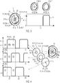
- Fig. 1 shows an iris device 1, which is embodied as a single iris 3.
- the single iris 3 also represents the aperture arrangement 5, which is shown in five different states comprising an open state 7 and a closed state 9 of an aperture 5a.
- the upper panel of Fig. 1 shows five exemplary images 13 detected by a sensor 15.
- the sensor 15 may be embodied as a camera 15a.
- a first image 13a does not show any artifacts caused by a low light intensity
- a second image 13b shows artifacts due to the low light intensity
- the images 13 comprise two objects 17 which are located at different distances to the optical imaging system.
- Fig. 2 shows the advantages of a multispectral iris device 1a over a conventional iris device 1b.
- the images 13 shown in Fig. 2 are exemplarily taken with an optical microscope with two different operation modes.
- an open state 7 will result in an open state result 7a
- the closed state 9 of the Iris 3 will result in a closed state result 9a.
- the color reflectance image 19 which is obtained by illumination of a sample with a source of illumination 18, comprises blurred regions 21 and the fluorescence image 23 clearly shows fluorescent structures 25.
- the fluorescence image 23 is also obtained by illumination with a source of illumination 18, wherein different sources of illumination 18 may be applied for the color reflectance image 19 and the fluorescence image 23.
- the color reflectance image 19 does not show any blurred regions 21 and is completely focused, whereas the fluorescence image 23 is completely black and does not show any fluorescent structure 25.
- a conventional iris device 1b always requires deciding a setting of the conventional iris device 1b, which is between the optimum for the color reflectance mode and the optimum for the fluorescence mode.
- Fig. 2 represents the color reflectance image 19 and fluorescence image 23 recorded with the inventive multispectral iris device 1a.
- the color reflectance image 19 does not show any blurred region 21 and the fluorescence image 23 does, at the same time, show clear fluorescent structures 25.
- the inventive multispectral iris device 1a allows simultaneously providing the optimal setting for the color reflectance mode and the fluorescence mode.
- Fig. 3 shows that the first embodiment of an inventive iris device 1, which comprises an aperture arrangement 5 and two apertures 5a, a first aperture 5b represents the open state 7 and has a diameter D which equals the maximum diameter D max .
- the first aperture 5a is limited by an iris frame 27.
- the iris frame 27 surrounds a filter system 26 and receives a substrate 29 which comprises a filter 31, which is comprised of a filter layer 32 with a plurality of sub-layers 33 of at least two different dielectric materials 35.
- the different dielectric materials 35 may have a different refractive index 36a and/or a different layer thickness 36b.
- the filter 31 is embodied in a ring-shape 37, i.e. the filter surrounds a central aperture region 39 with an outer portion 38, the central aperture region 39 having an aperture diameter D which is a first diameter D 1 which is smaller than the maximum diameter of the apertures D max .
- the central apertures region 39 is an untreated portion 39a.
- the right-hand side of Fig. 3 shows a functional dependence of the transmissivity 41 on the wavelength 43.
- the simplified filter characteristics 45 shows a bandpass filter 47 which defines two different spectral bands 49, namely, as shown in Fig. 3 , the fluorescence band 51 and a residual spectral band 53, which is, simply speaking, comprising all wavelengths 43 spectrally located below the fluorescence band 51.
- the fluorescence band 51 is a light transmitting spectral band 54 for the filter system 26 of the iris device 1 shown in Fig. 3
- the residual spectral band 53 is a light blocking spectral band 56.
- the filter characteristics 45 indicate that within the fluorescence band 51, the transmissivity 41 of the bandpass filter 47 equals 1, whereas for the residual spectral band 53 the transmissivity 41 equals 0.
- the ring-shaped filter 31 acts as an iris 3 with a first aperture 5b for all wavelengths 43 smaller than the wavelength 43 of the fluorescence band 51.
- All wavelengths 43 of the fluorescence band 51 are transmitted through an iris 3 with a second aperture 5c, which in this case corresponds to an open state 7 of the iris 3.
- the residual spectral band 53 which may be the spectral band 49 of the color reflection mode, is affected by the first aperture 5b which is in a closed state 9, which consequently increases the depth of field for the residual spectral band 53.
- the fluorescence band 51 which may be a spectral band 49 with a low light intensity, profits from an open state 7 of the iris 3.
- An optical axis 69 is not shown in Fig. 3 for reasons of clarity but may be seen in Fig. 4 .
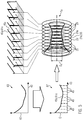
- Fig. 4 shows a second embodiment of the inventive multispectral iris device 1a, which comprises three individual substrates 29, each comprising a filter 31.
- Each of the filters 31 is embodied in a ring-shape 37 and comprises a central aperture region 39 having a first aperture diameter D 1 , a second aperture diameter D 2 and a third aperture diameter D 3 .
- the inventive multispectral iris device 1a is oriented essentially centered and perpendicular to the optical axis 69, which is defined by the optical imaging system (see Fig. 6 ).
- a light-transmission direction 70 is indicated as well, which is oriented parallel to the optical axis 69.
- the third diameter D 3 is smaller than the first diameter D 1 , which is in turn smaller than the second diameter D 2 .
- each of the three filters 31 comprises a filter characteristics 45 being denoted 45a, 45b and 45c.
- Each filter 31 is a band-stop filter 55, more specifically a multiple band-stop filter 55a.
- the first 45a, second 45b and third filter characteristics 45c belong to a first 55b, a second 55c and a third band-stop filter 55d and will be explained in the following with the short-wavelength side 57 of the filter characteristics 45 shown, as the principal is repeated on the long-wavelength side 59.
- Each of the filter characteristics 45a, 45b and 45c comprises at least two spectral bands 49, namely a spectral stop band 61 which is the light blocking spectral band 56 and which is spectrally located adjacent to at least one residual spectral band 53.
- the embodiment of the multispectral iris device 1a shown in Fig. 4 separates the short-wavelength side 57 in three spectral bands 49a, 49b and 49c, whose separation is valid for all three filter characteristics 45a-45c.
- the first filter characteristic 45a yields a zero transmissivity 41 for the first spectral band 49a
- the second filter characteristics 45b yields a zero transmissivity 41 for the second spectral band 49b
- the third filter characteristics 45c yields a zero transmissivity 41 for the third spectral band 49c.
- Each filter characteristics 45a-45c yields a transmissivity 41 of one for the two out of the three spectral bands 49a-49c which are not the spectral stop band 61 of the corresponding filter characteristics 45a-45c.
- Fig. 4 furthermore shows that the spectral band 49a-49c are adjacent to each other but do not overlap, i.e. there is no wavelength which is neither blocked by the first filter 31a, nor by the second filter 31b, nor by the third filter 31c.
- filter characteristics 45a-45c shown in the left-hand side of Fig. 4 are combined with the spatial structure of the filter, i.e. the ring-shape 37 and the corresponding aperture diameter D 1 -D 3 .
- the spectral stop band 61 of the first filter characteristics 45a is transmitted through an iris 3 with a diameter D 1
- the spectral stop band 61 of the second filter characteristics 45b is transmitted through an iris 3 of diameter D 2
- the spectral stop band 61 of the third filter characteristics 45c is transmitted through an iris 3 of the diameter D 3 .
- Fig. 5 shows a third embodiment of the inventive multispectral iris device 1a and respective design steps.
- the plot shown in the upper left side of Fig. 5 illustrates the desired throughput plot 63 which shows the functional dependence of the throughput 65 on the wavelength 43.
- Fig. 5 illustrates the functional dependence of the aperture diameter D on the wavelength 43.
- This diameter plot 67 is calculated from the desired throughput plot 63.
- a diameter D may be determined.
- the corresponding aperture diameter D e may also be seen in the lower right panel of Fig. 5 , where the corresponding example substrate 29e is provided with an example filter 31e.
- the example filter 31e has an example filter characteristics 45e, which is shown in the upper right panel of Fig. 5 .
- the band-stop filter 55 comprises a spectral stop band 61, which corresponds to the example spectral band 49e.
- the aperture diameter D e only applies to the example spectral band 49e which corresponds to the example spectral stop band 61e.
- Wavelengths 43 located outside the example spectral stop band 61e are not affected by the example filter 31e and are transmitted through the respective example filter 31e.
- each of the plurality of filters 29 only applies to the corresponding spectral stop band 61 indicated in the upper right panel of Fig. 5 .
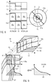
- Fig. 6 shows a fourth embodiment of the inventive iris device 1, wherein the iris device 1 comprises an aperture magazine 64 which is embodied as a filter wheel 66.
- the filter wheel 66 receives, in the embodiment shown, four aperture arrangements 5 in four moveable iris receptacles 68 of the filter wheel 66.
- the optical imaging system 71 is only indicated and may for instance be a medical imaging system 72.
- Fig. 7 shows a fifth embodiment of the inventive iris device 1 in which a known mechanical diaphragm 73 with components 75 is combined with the inventive filters 31.
- Each of the components 75 is embodied as a blade 77 with a kidney-shaped, which is only indicated in the left diaphragm 73 of Fig. 7 for reasons of clarity.
- Fig. 7 shows one isolated blade 77 which is fixed at a rotation center 79 and which may be moved towards the optical axis 69, which is indicated as an encircled X.
- the aperture diameter D of the resulting filter geometry is a variable diameter D d .
- the resulting variable diameter D d only applies to the spectral band (not shown) which is affected by the filter 31 used.
- Fig. 7 shows a diaphragm 73 with a second embodiment of blades 77 of a different shape.
- Fig. 8 shows a sixth embodiment of the inventive iris device 1 which is comprising two edge filters 81, wherein the shown iris device 1 is used for color imaging, in particular to tune the relative intensity of colors inverse proportionally to the sensors sensitivity.
- the iris device 1 comprises of two edge filters 81a and 81b having a first filter characteristics 45a and a second filter characteristics 45b.
- Each of the edge filters 81 is embodied as a low-past filter 83, i.e. wavelengths 43 shorter than an edge wavelength 85 are completely transmitted, whereas wavelengths 43 longer than the edge wavelength 85 are blocked by the corresponding edge filter 81.
- the edge wavelength 85 represents a spectral filter edge 86.
- the first edge filter 81a has a first edge wavelength 85a and the second edge filter 81b has a second edge wavelength 85b. All wavelengths 43 shorter than the first edge wavelength 85a are completely transmitted by either of the two edge filters 81 and interact with the aperture of diameter D corresponding to the open state 7. Those wavelengths constitute a first spectral band 49a.
- Wavelengths of the first spectral band 49a have a first aperture diameter D 1 .
- the second spectral band 49b located in between the two edge wavelengths 85a and 85b have an aperture diameter D 2 and wavelengths located in the third spectral band 49c have the aperture diameter D 3 .
- Fig. 9 shows a seventh embodiment of the inventive iris device 1, which is embodied as a linear variable edge filter 87.
- the linear variable edge filter 87 comprises a multitude of filter characteristics 45 which are shown in different plots.
- a first plot 89a shows the dependence of the transmissivity 41 on the wavelength 43, whereas the different edge wavelengths 85 shown correspond to different radiuses D/2.
- a second plot 89b represents the desired throughput plot 63 and shows the dependence of the radius D/2 on the edge wavelength 85.
- the third plot 89c is a three-dimensional plot of the transmissivity 41, the wavelength 43 and the radius D/2.
- the third plot 89c shows the dependence of the transmissivity 41 on the spatial coordinate, the radius D/2 and the spectral coordinate, the wavelength 43.
Landscapes
- Physics & Mathematics (AREA)
- General Physics & Mathematics (AREA)
- Optics & Photonics (AREA)
- Analytical Chemistry (AREA)
- Chemical & Material Sciences (AREA)
- Health & Medical Sciences (AREA)
- General Health & Medical Sciences (AREA)
- Surgery (AREA)
- Engineering & Computer Science (AREA)
- Multimedia (AREA)
- Microscoopes, Condenser (AREA)
- Endoscopes (AREA)
- Diaphragms For Cameras (AREA)
- Blocking Light For Cameras (AREA)
Description
- The invention relates to an iris device for optical imaging systems, comprising an aperture arrangement. The invention further relates to a medical imaging system comprising a sensor, in particular a camera.
- Conventional iris devices are known in the art and are commonly used in optical imaging systems. A single iris is the simplest embodiment of an iris device. The iris or aperture stop is an important element in most optical systems. The iris of an optical system limits the amount of light passing through said optical system and reaching a sensor. If the iris is not embodied as a separate element, the optical elements of the optical system itself may constitute the iris, e.g. by the diameter of a lens.
- In
US 2013/0016220 A1 , passive multi-band aperture filters and cameras are disclosed. They may be embodied as a dual-band or three-band aperture filter comprising individual coatings for each filter portion. -
US 2010/066854 A1 discloses a camera and imaging system with a plurality of different depths of field for a first frequency and a second frequency of optical radiation, wherein the filter portions comprise different optical filters. -
US 2010/079884 A1 discloses a dichroic aperture for an electronic imaging device separating a lens into a first and second aperture. - However, as monochromatic aberrations of the optical system increase with the possible distance of a light beam, which is a common model for the description of optical systems, to the optical axis of the optical system, it is often desired to limit the light beams passing through the optical system to paraxial light beams, i.e. light beams in the proximity of the optical axis.
- In the art, commonly iris diaphragms are applied for this purpose. Such iris diaphragms allow to variably determine the amount of light which is passing through the optical system.
- The iris or aperture stop further effects the depth of field (DOF) of the optical system. The DOF, also called depth of sharpness or depth of focus, defines the range of distances which can be focused by an optical imaging system.
- The DOF shows an inverse functional dependence on the diameter of the aperture, wherein the diameter of the aperture corresponds to twice the distance of a light beam farthest away from the optical axis. Those light beams with the maximum possible distance away from the optical axis may be referred to as marginal rays.
- In other words, the larger the diameter of the aperture, the shallower is the DOF. A decreasing diameter of the aperture, on the contrary, increases the DOF. Consequently, in irises of the art, the amount of light passing through an optical system, in particular an optical imaging system, may only be increased at the expense of a shallower DOF.
- Accordingly, an increased DOF may only be obtained at the expense of a decreased amount of light transmitted through the optical system.
- Therefore, a conventional iris unavoidably results in a trade-off between the DOF and the amount of light transmitted through the optical system, i.e. in particular the amount of light incident on the sensor.
- Surgical microscopes, as an exemplary field of application, offer different imaging modes which may have different optical iris settings. Specifically, in color reflectance mode, illumination of a sample may be sufficiently intense, and conveniently a conventional iris is used to set a small diameter which increases the DOF, thus allowing better focus of uneven surfaces.
- In a fluorescence mode of the exemplary surgical microscope, a sample is excited by illumination with radiation having an excitation wavelength, wherein the sample emits fluorescent light upon its excitation. The fluorescent light is commonly red-shifted, i.e. the fluorescence wavelength is longer than the excitation wavelength.
- As the number of photons of the fluorescence emitted per exciting photon, i.e. the quantum yield, is commonly well below 10 %, the iris should be open to collect as many of the fluorescence photons as possible.
- The simultaneous inspection of a sample in color reflectance mode and fluorescence mode therefore requires a compromise, since a conventional iris does not allow simultaneous application of different aperture sizes. Either the DOF is increased at the expense of the fluorescence sensitivity or the fluorescence sensitivity is increased at the expense of a decreased DOF.
- An iris of the art transmits or rejects light in the same way for all wavelengths, i.e. it is not wavelength-selective and shows a spectrally flat transmission property.
- One object of the present invention is therefore to provide an iris device which overcomes the above disadvantages of prior art iris devices, and which, referring exemplarily to the above-mentioned example, may provide an open aperture for fluorescence light and a closed aperture for the color reflectance, thereby allowing simultaneous optimal iris settings for both imaging modes.
- The disadvantages of prior art iris devices are overcome by the iris device mentioned in the beginning by providing an iris device whose aperture arrangement comprises an integrated filter system limiting the light at different degrees at at least two different wavelengths and in that the filter system comprises at least one ring-shaped edge filter which surrounds a central aperture region, wherein the central aperture region is an aperture.
- The inventive iris device may therefore simultaneously limit the light at two or more wavelengths at different degrees.
- The at least two wavelengths may be located in at least two discrete non-overlapping spectral bands.
- A first range of wavelengths may compose a first waveband being effected by the filter system with a first degree of limitation.
- Further, a second range of wavelengths may compose a second waveband being effected by the filter system simultaneously with the first waveband but with a second degree of limitation being different to the first degree of limitation.
- In an embodiment of the inventive iris device, the filter system comprises a filter with at least one light transmitting spectral band.
- The light transmitting spectral band may have a transmission close to 1 for at least one wavelength, preferably for a multitude of wavelengths or a range of wavelengths. A range of wavelengths, i.e. a spectral band encompasses an infinite number of individual wavelengths. The transmission is preferably constant over the complete spectral band.
- In yet another embodiment of the inventive iris device, the filter system comprises a filter with at least one light blocking spectral band.
- The at least one light blocking spectral band may have a transmission close to zero, i.e. it may be opaque for at least one wavelength, preferably for a multitude of wavelengths or a range of wavelengths, wherein the transmission is preferably constant over the complete range, i.e. the complete spectral band. The complete spectral band with transmission of 1 most preferably does not overlap with the spectral band of zero transmission.
- The medical imaging system mentioned above overcomes the disadvantages of prior art medical imaging systems in that it comprises at least one inventive iris device.
- In the following, further embodiments of the present invention will be described. Those embodiments are advantageous on their own, whereas technical features of the embodiments may be arbitrarily combined or omitted to improve the above embodiment of the inventive iris.
- The inventive iris device represents a multispectral iris device, the transmission behavior of which depends on the wavelength, i.e. varies along the optical spectrum. The multispectral iris device thus comprises a multispectral aperture arrangement which may alternatively be denoted as multispectral imaging aperture or multispectral imaging iris.
- In an embodiment of the inventive iris device, the central aperture region is the aperture, in particular, for one of the at least two discrete non-overlapping spectral bands.
- The edge filter may comprise a spectral filter edge which spectrally separates a first spectral band from a second spectral band.
- This embodiment has the advantage that the means for providing two different apertures at the at least two discrete non-overlapping spectral bands are embodied by one single filter.
- The filter system preferably denotes a part of the iris, which comprises at least one filter. The filter system may therefore comprise a frame for receiving the filter and for fixing and stabilizing the filter. The filter system may comprise two or more filters and may arrange said filters adjacent to each other in an aligned manner, whereas the filter system may also align different filters in a small angle to each other in order to avoid parallel surfaces, which may represent a Fabry-Perot interferometer.
- The edge filter may have two distinct filter bands, i.e. two discrete non-overlapping spectral bands, whereas the linear transmission in one band may be preferably more than 90 % smaller, more preferably more than 95 % smaller and most preferably more than 99 % smaller than in the second band. The ideal edge filter may be designed to transmit 100 % of the incoming light in the first spectral band and to block 100 % of the incoming light in the second spectral band. The ideal edge filter furthermore may comprise an infinitely steep edge that an edge wavelength, whereas no other transmission values except 0 % and 100 % may exist.
- A real world filter may not comprise such an infinitely steep filter edge and may thus comprise a functional dependence of the transmission on wavelength which may be similar to a sigmoid function.
- The edge filter is embodied in a ring-shape, i.e. surrounds an inner portion without the filter, which is the aperture region. The inner portion is circular and comprises a diameter, which defines the aperture diameter for the spectral band being blocked by the edge filter.
- The edge filter may be a low-pass or high-pass filter, wherein the low-pass filter may be highly transparent for wavelengths smaller than an edge wavelength and opaque for wavelengths higher than the edge wavelength. The high-pass filter may be opaque for wavelengths smaller than the edge wavelength and highly transparent for wavelengths higher than the edge wavelength. In this disclosure, the term "highly transparent" denotes a transmissivity close to 1 and the term "opaque" denotes a transmissivity close to zero.
- It is furthermore noted that a high-pass filter in the wavelength domain corresponds to a low-pass filter in the frequency domain.
- An edge filter as described above may also comprise a highly transparent spectral band for which the transmissivity is below 1, however, the spectral band transmitted through the ring-shaped outer region of the filter would be attenuated, which in turn may compromise the homogeneity of illumination with the transmitted spectral band.
- One exemplary edge filter of this embodiment may thus be transparent for the spectral band of fluorescence emission, but may be opaque for the rest of the spectrum. A physical aperture at the center of such a filter, i.e. the central aperture region, makes the inventive iris device behave like a conventional closed iris for the rest of the spectrum, while the filter is highly transparent at the fluorescence emission spectral band, i.e. the filter is essentially invisible for fluorescence light. Consequently, the filter behaves like a conventional iris completely open for the fluorescence emission spectral band.
- The rest of the spectrum denotes light with a wavelength below the edge wavelength of the high-pass edge filter, in particular below the spectral band of fluorescence emission.
- This embodiment of the inventive iris device is therefore a multispectral iris device and provides an open aperture for the fluorescence emission spectral band, in which band only a low light intensity is available as compared to the visible spectral band, for which the multispectral iris device provides a closed aperture. By such means, a color reflectance mode of a surgical microscope, which mode applies the visible spectral band, may profit from a closed aperture and consequently the resulting increased DOF, whereas the simultaneously applied fluorescence mode, which applies the fluorescence emission spectral band, may profit at the same time from a completely open aperture, which allows collecting as many of the rare fluorescence photons as possible.
- One of the at least two discrete non-overlapping spectral bands may comprise a fluorescence band of a sample under study, i.e. the fluorescence wavelength may be transmitted through the inventive iris device with a first aperture, whereas visible wavelengths in a second spectral band, this second spectral band being different from the first spectral band comprising the fluorescence band, may be transmitted through the inventive iris device with a second aperture being different to the first aperture. Different apertures are to be understood as apertures with a different diameter.
- Consequently, in the particular example given above, the fluorescence band may be transmitted through the iris device with the aperture being open, whereas the second spectral band may be transmitted through the iris with a decreased throughput.
- An iris device may be embodied as a disc-shaped element, wherein the disc may comprise a ring-shaped iris frame which may surround the aperture arrangement. The iris frame may have an inner diameter, which may represent the maximum diameter Dmax. An open aperture is therefore to be understood as an iris with the diameter Dmax.
- Aperture diameters D being smaller than Dmax result in an increased attenuation, respectively a decreased throughput which may be easily calculated with the following formula:

- The light-transmission direction of the iris device is a direction parallel to an optical axis of the iris device. The light-transmission direction may be unidirectional or bidirectional.
- The coaxial arrangement of the at least two apertures with respect to the light-transmission direction is to be understood in the sense that the at least two apertures are each being positioned essentially centered and essentially perpendicular to the optical axis.
- An aperture is to be understood as an element that limits light by means of a portion of the aperture blocking the light. The aperture commonly denotes the opening which transmits the light but may also be understood as an element comprising such an opening.
- A spectral band is to be understood as a range of wavelengths or optical frequencies.
- In another embodiment of the inventive iris device, the aperture arrangement may simultaneously comprise at least two apertures which may be arranged coaxially with respect to a light-transmission direction, wherein each of the at least two apertures may limit light in a different spectral band of at least two discrete non-overlapping spectral bands.
- In a further advantageous embodiment of the inventive iris device, the filter system may comprise at least one ring-shaped band-stop filter limiting the light of at least one of the at least two discrete non-overlapping spectral bands.
- A band-stop filter may have the advantage that the light of a predetermined spectral band may be limited by such a band-stop filter. The affected spectral band may be denoted as spectral block band (the light blocking spectral band) and may comprise a predetermined wavelength region. Only light of wavelengths in the spectral block band may be limited by the band-stop filter.
- The band-stop filter may be embodied as the above described edge filter, i.e. it may be embodied in a ring-shape with a physical aperture in its center. The physical aperture may therefore be highly transparent for all wavelengths incident on the band-stop filter, whereas all wavelengths located in the spectral block band may be blocked in the ring-shaped outer portion of the band-stop filter and may be transmitted through the physical aperture only. All wavelengths located in the spectral block band may therefore be transmitted through an aperture of diameter D, whereas wavelengths not comprised in the spectral block band are transmitted through an aperture of diameter Dmax, with D being smaller than Dmax.
- Limiting the light of at least one of the at least two discrete non-overlapping spectral bands is therefore to be understood as clipping or reducing the aperture for light of the spectral block band.
- The band-stop filter may preferentially be opaque for the spectral block band and preferentially highly transparent for the spectral bands adjacent to the spectral block band.
- In another advantageous embodiment of the inventive iris device, the filter system may comprise at least one bandpass filter.
- A bandpass filter may be advantageous if a pre-selection of a spectral band to be observed is desired.
- The bandpass filter may comprise a spectral transmission band and two spectrally adjacent spectral block bands.
- The combination of two edge filters may represent the easiest way for obtaining such a bandpass filter.
- The bandpass filter of this embodiment may comprise a low-pass edge filter and a high-pass edge filter, wherein the filter edge of the low-pass edge filter may be located at a low-pass wavelength which is higher than a high-pass wavelength, the high-pass wavelength representing the filter edge of the high-pass edge filter. For wavelengths located between the high-pass wavelength and the low-pass wavelength, the bandpass filter may be highly transparent, whereas it may be opaque for all wavelengths lower than the high-pass wavelength and higher than the low-pass wavelength.
- In another embodiment of the inventive iris device, a multitude of filters is comprised. The filters are preferentially band-stop filters and this embodiment may further comprise a bandpass filter for pre-selecting the spectral band to be observed.
- The embodiment comprising only a multitude of band-stop filters has the advantage that, according to the number of band-stop filters, a multitude of apertures may be provided for the respective spectral bands, which apertures only apply to the respective spectral band affected by the respective individual band-stop filter. In other words, for each spectral band of the multitude of spectral bands, a different aperture may apply, which in turn denotes that each spectral band of the multitude of spectral bands may have a different throughput and the different throughput of the spectral bands may form a specific throughput spectrum.
- In yet another embodiment of the inventive iris device, the aperture of a first spectral band defined by a first band-stop filter is smaller or larger than each of the apertures of a second and third spectral band defined respectively by a second and third band-stop filter, the first spectral band being spectrally located between the second and a third spectral band.
- This embodiment of the inventive iris device may thus provide a wavelength-dependent local minimum or local maximum in aperture diameters, i.e. the specific throughput spectrum desired may advantageously comprise local minima and/or local maxima as well.
- In another embodiment of the inventive iris device, the filter system comprises at least one linear variable edge filter having a spectral filter edge, whose spectral filter edge varies depending on the distance to an optical axis of the iris device.
- This embodiment is especially advantageous if only one single filter may be received in the filter system, e.g. due to spatial limitations.
- The variation of the filter edge, i.e. the edge wavelength, therefore varies along a radial direction, wherein the radial direction is oriented essentially perpendicular to the optical axis of the iris device.
- The linear variable edge filter of this embodiment may be a short-past filter which transmits only wavelengths shorter than the wavelength of the filter edge, wherein this wavelength of the filter edge varies linearly along the radial direction. It is therefore conceivable to provide a multispectral iris device with a single filter comprising one single coating, which coating furthermore matches a custom throughput spectrum with a high spectral resolution.
- It is noted that this embodiment, which is based on short- or long-pass filters, is limited to throughput spectra which are monotonic functions of the wavelength. A variable band-stop filter with a similar spatial dependence of the blocked spectral bands circumvents these limitations and allows providing multispectral iris devices with virtually any throughput spectrum.
- The at least one filter of the iris device may comprise a filter subsystem, which filter subsystem may comprise at least a substrate and at least one filter layer embodied on the substrate. Most preferably, a filter is fabricated by coating the substrate with the desired filter.
- The substrate may be chosen to be highly transparent for all spectral bands to be inspected and/or transmitted via the iris. Exemplarily, a substrate comprising a simple glass may be preferentially applied in the visible and near-infrared spectral range, whereas for applications using an ultraviolet spectral band, a substrate comprising exemplarily fused silica, quartz glass, fluorides or sapphire are more suitable.
- Another approach may be to choose the substrate such that certain undesired spectral bands may be blocked by the substrate itself, which may reduce the cost of an additional blocking filter. In such an approach for instance ultraviolet wavelengths may be blocked by the substrate. Similarly, substrates may be applied which block mid-infrared and infrared radiation in order to avoid heating of the samples under study.
- In another embodiment of the inventive iris device, a multitude of filter layers is embodied on a substrate.
- The multitude of filter layers may be embodied on a single substrate, i.e. on one and the same substrate, which has the advantage of preventing the occurrence of a Fabry-Perot interferometer introducing unwanted disturbing effects. Furthermore, such an embodiment saves costs and space, which may be especially advantageous in case of spatial limitations for the iris device.
- It is also possible that each filter is embodied on a separate substrate or that only a subset of a multitude of filters is embodied on a single substrate.
- An embodiment applying a single substrate has the further advantage that only one element has to be aligned within the iris device, in particular with respect to the optical axis, respectively the light-transmission direction of the iris device. The coaxial arrangement of the at least two apertures with respect to the light-transmission direction is therefore performed automatically within one step of production.
- In yet another embodiment of the inventive iris device, according to at least one of a source of illumination encompassing a range of spectral densities and a sensor used in the optical imaging system encompassing a range of spectral sensitivities, the first band-stop filter for the at least one first spectral band in which at least one of a high spectral density of the source of illumination and a high sensor sensitivity applies, are embodied with the first aperture, whose diameter is smaller than the diameter of the at least one second aperture of the second band-stop filter for a spectral band in which at least one of a low spectral density of the source of illumination and a low sensor sensitivity applies.
- This embodiment is especially advantageous in digital color imaging, where each of the colors, representing a separate spectral band, has a different optimal throughput. Two main factors which require or motivate using different throughputs for different colors are for example the sensor sensitivity and the light source spectrum.
- The sensor sensitivity is not a flat curve but is described by a function depending on the wavelength incident on the sensor. Silicon, for example, has considerable lower sensitivity for incident blue light (around 480 nanometers) and is commonly most sensitive in a spectral band covering the red light (around 650 nanometers) and the near infrared light (0.75-1.4 micron).
- Furthermore, light source spectra as for instance halogen bulbs emit according to the black body radiation law, i.e. for the visible spectrum, the intensity increases almost exponentially with the wavelength. Consequently, the spectral density in the blue spectral region is low, whereas it is high in the red and near-infrared region.
- Usually this suboptimal color distribution is compensated for by optical filters attenuating those spectral bands with high sensitivity or illumination intensity or by digital filters rebalancing the colors.
- The above embodiment of the inventive iris device allows addressing this problem in a more efficient way, as the different apertures provided for the different spectral bands attenuate the intensity of the corresponding spectral band in a way simultaneously increasing the DOF.
- Furthermore, digital filters rebalancing the colors incident on a sensor have the disadvantage that a spectral range with low intensity and a spectral range with high intensity may not be detected by the sensor with the same dynamic range. This disadvantage may be mitigated by means of the multispectral iris device of this embodiment, which allows the sensor to be operated within the same dynamic range for all colors.
- One simple example of this embodiment is to provide three apertures of different size, whereas the spectral band with the lowest sensor sensitivity respectively the lowest light intensity has the largest aperture for transmitting as much light as possible, the second spectral band with a medium sensor sensitivity respectively a medium light intensity has a medium aperture, whose size is smaller than for the first spectral band, finally the third spectral band with a high sensor sensitivity respectively a high light intensity is embodied with a small aperture, whose size is smaller than the aperture of the first spectral that band and smaller than the aperture of the second spectral band.
- Such an embodiment could be realized by providing two low-pass edge filters, wherein the spectral edge of the first filter is located in between the first and the second spectral band and provides the medium aperture, whereas the second lower-pass edge filter comprises a spectral edge located in between the second and third spectral band and provides the small aperture. The first spectral band is therefore transmitted through the first and second filter and is solely affected by the maximum diameter Dmax of the aperture arrangement.
- Using a multitude of such filters, a high spectral resolution and consequently a high correction accuracy may be obtained by the multispectral iris device of this embodiment.
- In another embodiment of the inventive iris device the filter layer comprises a plurality of sub-layers of at least two different dielectric materials with at least one of different refractive indices and different layer thicknesses, wherein the different sub-layers are at least partially embodied on the substrate in an alternating manner, and in that the filter layer is embodied on an outer portion of the substrate which encloses an untreated portion, the dimension of the untreated portion within the plane of the substrate defining the diameter of the aperture.
- Commonly, highly efficient mirrors and optical devices as filters are obtained by providing the substrate with a dielectric coating, wherein a dielectric coating comprises a multitude of single layers. The refractive indices, the layer thicknesses and the number of such layers, as well as the refractive index of the adjacent layer define the reflection or transmission behavior which furthermore depends on the wavelength.
- Recent advancements in optical filter design and manufacturing allow for highly reflective layers, highly transmissive layers, partly transmissive layers and the above described filters with different filter characteristics.
- One filter layer may therefore define a multitude of spectral bands which are individually affected by the filter layer. By providing the filter layer in a ring-shape, the effect of the filter layer on a specific spectral band therefore only applies in the outer portion of the ring, the untreated surrounded portion consequently defines the diameter of the aperture for each of the affected spectral bands.
- In another embodiment of the iris device at least one of the at least two apertures has, for a given spectral band, a variable diameter.
- This embodiment has the advantage that a first spectral band may have a fixed aperture size, whereas the aperture size of a second spectral band, which may be subject to changing illumination conditions, may be varied according to changed conditions.
- In another embodiment of the iris device, the iris device comprises a diaphragm with a variable diameter, wherein components of the diaphragm have a spectral selective light transmissivity.
- This embodiment has the advantage, that the matured filter design and coating manufacturing may be combined with opto-mechanical developments.
- The components of the diaphragm may be a plurality of blades which are rotatably mounted at a circumferential portion of the diaphragm, wherein each blade of the plurality of blades is rotatable towards the center of the iris. The blades of the plurality of blades may comprise a first synchronizing element and a second synchronizing element for being synchronized to each other for performing an identical rotational movement. Each synchronizing element may be engaged to the synchronizing element of the adjacent blade such that a synchronized rotational movement of the plurality of blades may result in an increased or decreased aperture diameter.
- Each blade of the plurality of blades may be embodied such that only a portion of the blade reaching into the maximum aperture of the aperture arrangement may comprise a filter of one of the aforementioned type. In particular, the synchronizing elements may be embodied at a portion of the individual blade which is made of a non-filter material, i.e. a metal.
- The diaphragm may comprise any arbitrary number of blades, wherein different shapes of the blades are conceivable. Possible shapes are for instance a triangular shape, a rectangular shape or a kidney-shape, whereas the kidney-shape is preferred, as in general curved blades improve the roundness of the aperture opening.
- In another embodiment of the inventive iris device, the iris device comprises an aperture magazine, the aperture magazine receives at least two aperture arrangements, each in a movable iris receptacle, wherein one of the at least two movable iris receptacles is moved into the optical axis of the optical imaging system.
- This embodiment of the iris device has the advantage that different subsets of iris devices may be stored in the aperture magazine and easily applied to the optical imaging system.
- Only one aperture arrangement may be provided in the light transmission path, that is, only one subset of the plurality of aperture arrangements affects the light transmitted through the iris device. The other, i.e. the non-active aperture arrangement, may be stored outside the optical path of the light transmitted through the iris device.
- The apertures magazine may further comprise a moving device for storing and transporting the individual apertures devices out of or into the light transmission of the iris device.
- In another embodiment of the inventive iris device the aperture magazine is embodied as a filter wheel.
- A filter wheel may be easily aligned with respect to the optical axis of the iris device and may be intuitively operated.
- During operation of an iris device according to this embodiment, a replacement of aperture arrangements currently not active, i.e. currently not inserted into the light transmission path, may be conceivable.
- The medical imaging system mentioned in the beginning may comprise an arbitrary number of the inventive iris devices of the same or different embodiments. Exemplary medical imaging systems comprise microscopes or surgical microscopes. Said medical imaging systems may provide different operation modes which may be simultaneously used. Exemplarily, as mentioned in the beginning, the color reflectance mode and fluorescence mode may be applied simultaneously by such an inventive medical imaging system.
- The invention is explained in greater detail below by way of example using several embodiments with reference to the appended drawings. The embodiments merely represent possible configurations in which individual features, as described above, can be realized and omitted independently of each other. In the description of the embodiments, for simplicity the same features and elements are provided with the same reference numerals.
- In the figures:
- Fig. 1
- illustrates the relationship between the aperture and the amount of transmitted light and the relationship between the aperture and the depth of field;
- Fig. 2
- illustrates the advantage of a multispectral iris device over a conventional iris device;
- Fig. 3
- illustrates a first embodiment of the inventive iris device;
- Fig. 4
- illustrates a second embodiment of the inventive iris device;
- Fig. 5
- illustrate a third embodiment of the inventive iris device;
- Fig. 6
- illustrates a fourth embodiment of the inventive iris device;
- Fig. 7
- illustrates a fifth embodiment of the inventive iris device;
- Fig. 8
- illustrates a sixth embodiment of the inventive iris device; and
- Fig. 9
- illustrates a seventh embodiment of the inventive iris device.
-
Fig. 1 shows aniris device 1, which is embodied as asingle iris 3. Thesingle iris 3 also represents theaperture arrangement 5, which is shown in five different states comprising anopen state 7 and a closed state 9 of anaperture 5a. - In between the
open state 7 and a closed state 9 threeintermediate states 11 are shown. The upper panel ofFig. 1 shows fiveexemplary images 13 detected by a sensor 15. The sensor 15 may be embodied as a camera 15a. - It can be seen that for an
open state 7 of theiris 3, respectively theaperture 5a, a first image 13a does not show any artifacts caused by a low light intensity, whereas for a closed state 9 of theiris 3, a second image 13b shows artifacts due to the low light intensity. - In the lower panel, five
images 13 are shown, whereas theimages 13 comprise twoobjects 17 which are located at different distances to the optical imaging system. - In case of an
open state 7 of theiris 3 only oneobject 17 may be sharply imaged whereas the other object appears blurred in the image. This is shown in the third image 13c, whereas in the fourth image 13d, which corresponds to the closed state 9 of theiris 3, bothobjects 17 are imaged sharply. -
Fig. 2 shows the advantages of amultispectral iris device 1a over aconventional iris device 1b. - The
images 13 shown inFig. 2 are exemplarily taken with an optical microscope with two different operation modes. In the case of theconventional iris device 1b anopen state 7 will result in anopen state result 7a, whereas the closed state 9 of theIris 3 will result in aclosed state result 9a. - In the
open state result 7a, thecolor reflectance image 19, which is obtained by illumination of a sample with a source ofillumination 18, comprisesblurred regions 21 and thefluorescence image 23 clearly showsfluorescent structures 25. Thefluorescence image 23 is also obtained by illumination with a source ofillumination 18, wherein different sources ofillumination 18 may be applied for thecolor reflectance image 19 and thefluorescence image 23. - On the contrary, if the closed state 9 of the
iris 3 is chosen, thecolor reflectance image 19 does not show anyblurred regions 21 and is completely focused, whereas thefluorescence image 23 is completely black and does not show anyfluorescent structure 25. - Therefore, a
conventional iris device 1b always requires deciding a setting of theconventional iris device 1b, which is between the optimum for the color reflectance mode and the optimum for the fluorescence mode. - The right-hand side of
Fig. 2 represents thecolor reflectance image 19 andfluorescence image 23 recorded with the inventivemultispectral iris device 1a. As can be seen, thecolor reflectance image 19 does not show anyblurred region 21 and thefluorescence image 23 does, at the same time, showclear fluorescent structures 25. - Thus, the inventive
multispectral iris device 1a allows simultaneously providing the optimal setting for the color reflectance mode and the fluorescence mode. -
Fig. 3 shows that the first embodiment of aninventive iris device 1, which comprises anaperture arrangement 5 and twoapertures 5a, a first aperture 5b represents theopen state 7 and has a diameter D which equals the maximum diameter Dmax. In other words, thefirst aperture 5a is limited by aniris frame 27. - The
iris frame 27 surrounds afilter system 26 and receives asubstrate 29 which comprises a filter 31, which is comprised of a filter layer 32 with a plurality of sub-layers 33 of at least two different dielectric materials 35. - The different dielectric materials 35 may have a different refractive index 36a and/or a different layer thickness 36b.
- The filter 31 is embodied in a ring-shape 37, i.e. the filter surrounds a
central aperture region 39 with an outer portion 38, thecentral aperture region 39 having an aperture diameter D which is a first diameter D1 which is smaller than the maximum diameter of the apertures Dmax. thecentral apertures region 39 is an untreated portion 39a. - The right-hand side of
Fig. 3 shows a functional dependence of thetransmissivity 41 on thewavelength 43. Thesimplified filter characteristics 45 shows a bandpass filter 47 which defines two differentspectral bands 49, namely, as shown inFig. 3 , the fluorescence band 51 and a residualspectral band 53, which is, simply speaking, comprising allwavelengths 43 spectrally located below the fluorescence band 51. The fluorescence band 51 is a light transmitting spectral band 54 for thefilter system 26 of theiris device 1 shown inFig. 3 , whereas the residualspectral band 53 is a light blocking spectral band 56. - The
filter characteristics 45 indicate that within the fluorescence band 51, thetransmissivity 41 of the bandpass filter 47 equals 1, whereas for the residualspectral band 53 thetransmissivity 41 equals 0. - Due to its
filter characteristics 45 the ring-shaped filter 31 acts as aniris 3 with a first aperture 5b for allwavelengths 43 smaller than thewavelength 43 of the fluorescence band 51. - All
wavelengths 43 of the fluorescence band 51 are transmitted through aniris 3 with a second aperture 5c, which in this case corresponds to anopen state 7 of theiris 3. - Therefore, the residual
spectral band 53, which may be thespectral band 49 of the color reflection mode, is affected by the first aperture 5b which is in a closed state 9, which consequently increases the depth of field for the residualspectral band 53. On the other hand, the fluorescence band 51 which may be aspectral band 49 with a low light intensity, profits from anopen state 7 of theiris 3. - An
optical axis 69 is not shown inFig. 3 for reasons of clarity but may be seen inFig. 4 . -
Fig. 4 shows a second embodiment of the inventivemultispectral iris device 1a, which comprises threeindividual substrates 29, each comprising a filter 31. Each of the filters 31 is embodied in a ring-shape 37 and comprises acentral aperture region 39 having a first aperture diameter D1, a second aperture diameter D2 and a third aperture diameter D3. - The inventive
multispectral iris device 1a is oriented essentially centered and perpendicular to theoptical axis 69, which is defined by the optical imaging system (seeFig. 6 ). A light-transmission direction 70 is indicated as well, which is oriented parallel to theoptical axis 69. - In
Fig. 4 the third diameter D3 is smaller than the first diameter D1, which is in turn smaller than the second diameter D2. - Furthermore, each of the three filters 31 comprises a
filter characteristics 45 being denoted 45a, 45b and 45c. Each filter 31 is a band-stop filter 55, more specifically a multiple band-stop filter 55a. - The first 45a, second 45b and third filter characteristics 45c belong to a first 55b, a second 55c and a third band-stop filter 55d and will be explained in the following with the short-
wavelength side 57 of thefilter characteristics 45 shown, as the principal is repeated on the long-wavelength side 59. - Each of the
filter characteristics spectral bands 49, namely aspectral stop band 61 which is the light blocking spectral band 56 and which is spectrally located adjacent to at least one residualspectral band 53. - The embodiment of the
multispectral iris device 1a shown inFig. 4 separates the short-wavelength side 57 in threespectral bands filter characteristics 45a-45c. - The first filter characteristic 45a yields a zero
transmissivity 41 for the firstspectral band 49a, thesecond filter characteristics 45b yields a zerotransmissivity 41 for the secondspectral band 49b, and the third filter characteristics 45c yields a zerotransmissivity 41 for the thirdspectral band 49c. - Each
filter characteristics 45a-45c yields atransmissivity 41 of one for the two out of the threespectral bands 49a-49c which are not thespectral stop band 61 of thecorresponding filter characteristics 45a-45c. -
Fig. 4 furthermore shows that thespectral band 49a-49c are adjacent to each other but do not overlap, i.e. there is no wavelength which is neither blocked by thefirst filter 31a, nor by thesecond filter 31b, nor by the third filter 31c. - Furthermore, the
filter characteristics 45a-45c shown in the left-hand side ofFig. 4 are combined with the spatial structure of the filter, i.e. the ring-shape 37 and the corresponding aperture diameter D1-D3. - In the present embodiment shown in
Fig. 4 , thespectral stop band 61 of thefirst filter characteristics 45a is transmitted through aniris 3 with a diameter D1, thespectral stop band 61 of thesecond filter characteristics 45b is transmitted through aniris 3 of diameter D2 and thespectral stop band 61 of the third filter characteristics 45c is transmitted through aniris 3 of the diameter D3. -
Fig. 5 shows a third embodiment of the inventivemultispectral iris device 1a and respective design steps. - The plot shown in the upper left side of
Fig. 5 illustrates the desiredthroughput plot 63 which shows the functional dependence of thethroughput 65 on thewavelength 43. - The lower left side of
Fig. 5 illustrates the functional dependence of the aperture diameter D on thewavelength 43. Thisdiameter plot 67 is calculated from the desiredthroughput plot 63. - In the diameter plot 67 a multitude of
spectral bands 49 is shown, whereas for each of thespectral bands 49 a diameter D may be determined. This is exemplarily shown for the examplespectral band 49e, which has an aperture diameter De. The corresponding aperture diameter De may also be seen in the lower right panel ofFig. 5 , where thecorresponding example substrate 29e is provided with anexample filter 31e. Theexample filter 31e has anexample filter characteristics 45e, which is shown in the upper right panel ofFig. 5 . - In the
example filter characteristics 45e the band-stop filter 55 comprises aspectral stop band 61, which corresponds to the examplespectral band 49e. In other words, the aperture diameter De only applies to the examplespectral band 49e which corresponds to the examplespectral stop band 61e. -
Wavelengths 43 located outside the examplespectral stop band 61e are not affected by theexample filter 31e and are transmitted through therespective example filter 31e. - In conclusion, each of the plurality of
filters 29 only applies to the correspondingspectral stop band 61 indicated in the upper right panel ofFig. 5 . -
Fig. 6 shows a fourth embodiment of theinventive iris device 1, wherein theiris device 1 comprises an aperture magazine 64 which is embodied as a filter wheel 66. The filter wheel 66 receives, in the embodiment shown, fouraperture arrangements 5 in four moveable iris receptacles 68 of the filter wheel 66. - Only one of the
aperture arrangements 5 is inserted into and aligned to theoptical axis 69 of the optical imaging system 71. The optical imaging system 71 is only indicated and may for instance be a medical imaging system 72. -
Fig. 7 shows a fifth embodiment of theinventive iris device 1 in which a knownmechanical diaphragm 73 with components 75 is combined with the inventive filters 31. Each of the components 75 is embodied as ablade 77 with a kidney-shaped, which is only indicated in theleft diaphragm 73 ofFig. 7 for reasons of clarity. - The left side of
Fig. 7 shows oneisolated blade 77 which is fixed at arotation center 79 and which may be moved towards theoptical axis 69, which is indicated as an encircled X. - If all
blades 77 of thediaphragm 73 shown inFig. 7 are rotated towards theoptical axis 69, the movement of allblades 77 is synchronized, the aperture diameter D of the resulting filter geometry is a variable diameter Dd. - As the
blades 77 of thediaphragm 73 are embodied as filters 31 with a corresponding filter characteristics (not shown), the resulting variable diameter Dd only applies to the spectral band (not shown) which is affected by the filter 31 used. - The right-hand side of
Fig. 7 shows adiaphragm 73 with a second embodiment ofblades 77 of a different shape. -
Fig. 8 shows a sixth embodiment of theinventive iris device 1 which is comprising two edge filters 81, wherein the showniris device 1 is used for color imaging, in particular to tune the relative intensity of colors inverse proportionally to the sensors sensitivity. - The
iris device 1 comprises of twoedge filters first filter characteristics 45a and asecond filter characteristics 45b. - Each of the edge filters 81 is embodied as a low-past filter 83, i.e.
wavelengths 43 shorter than anedge wavelength 85 are completely transmitted, whereaswavelengths 43 longer than theedge wavelength 85 are blocked by the corresponding edge filter 81. Theedge wavelength 85 represents a spectral filter edge 86. - The
first edge filter 81a has a first edge wavelength 85a and thesecond edge filter 81b has a second edge wavelength 85b. Allwavelengths 43 shorter than the first edge wavelength 85a are completely transmitted by either of the two edge filters 81 and interact with the aperture of diameter D corresponding to theopen state 7. Those wavelengths constitute a firstspectral band 49a. - Wavelengths of the first
spectral band 49a have a first aperture diameter D1. - Accordingly, the second
spectral band 49b located in between the two edge wavelengths 85a and 85b have an aperture diameter D2 and wavelengths located in the thirdspectral band 49c have the aperture diameter D3. -
Fig. 9 shows a seventh embodiment of theinventive iris device 1, which is embodied as a linearvariable edge filter 87. - The linear
variable edge filter 87 comprises a multitude offilter characteristics 45 which are shown in different plots. Afirst plot 89a shows the dependence of thetransmissivity 41 on thewavelength 43, whereas thedifferent edge wavelengths 85 shown correspond to different radiuses D/2. - A second plot 89b represents the desired
throughput plot 63 and shows the dependence of the radius D/2 on theedge wavelength 85. - The
third plot 89c is a three-dimensional plot of thetransmissivity 41, thewavelength 43 and the radius D/2. Thethird plot 89c shows the dependence of thetransmissivity 41 on the spatial coordinate, the radius D/2 and the spectral coordinate, thewavelength 43. -
- 1
- iris device
- 1a
- multispectral iris device
- 1b
- conventional iris device
- 3
- iris
- 5
- aperture arrangement
- 5a
- aperture
- 5b
- first aperture
- 5c
- second aperture
- 7
- open state
- 7a
- open state result
- 9
- closed state
- 9a
- closed state result
- 11
- intermediate state
- 13
- images
- 13a
- first image
- 13b
- second image
- 13c
- third image
- 13d
- fourth image
- 15
- sensor
- 15a
- camera
- 17
- object
- 18
- source of illumination
- 19
- color reflectance image
- 21
- blurred region
- 23
- fluorescence image
- 25
- fluorescent structure
- 26
- filter system
- 27
- iris frame
- 29
- substrate
- 29e
- example substrate
- 31
- filter
- 31a
- first filter
- 31b
- second filter
- 31c
- third filter
- 31e
- example filter
- 32
- filter layer
- 33
- plurality of sub-layers
- 35
- dielectric material
- 36a
- refractive index
- 36b
- layer thickness
- 37
- ring-shape
- 38
- outer portion
- 39
- central aperture region
- 39a
- untreated portion
- 41
- transmissivity
- 43
- wavelength
- 45
- filter characteristics
- 45a
- first filter characteristics
- 45b
- second filter characteristics
- 45c
- third filter characteristics
- 45e
- example filter characteristics
- 47
- bandpass filter
- 49
- spectral band
- 49a
- first spectral band
- 49b
- second spectral band
- 49c
- third spectral band
- 49e
- example spectral band
- 51
- fluorescence band
- 53
- residual spectral band
- 54
- light transmitting spectral band
- 55
- band-stop filter
- 55a
- multiple band-stop filter
- 55b
- first band-stop filter
- 55c
- second band-stop filter
- 55d
- third band-stop filter
- 56
- light blocking spectral band
- 57
- short-wavelength side
- 59
- long-wavelength side
- 61
- spectral stop band
- 63
- desired throughput plot
- 64
- aperture magazine
- 65
- throughput
- 66
- filter wheel
- 67
- diameter plot
- 68
- iris receptacle
- 69
- optical axis
- 70
- light-transmission direction
- 71
- optical imaging system
- 72
- medical imaging system
- 73
- diaphragm
- 75
- component
- 77
- blade
- 79
- rotation center
- 81
- edge filters
- 81a
- first edge filter
- 81b
- second edge filter
- 85
- edge wavelength
- 86
- spectral filter edge
- 87
- linear variable edge filter
- 89a
- first plot
- 89b
- second plot
- 89c
- third plot
- D1
- first diameter
- D2
- second diameter
- D3
- third diameter
- Dmax
- maximum diameter
- De
- example diameter
- Dv
- variable diameter
- D/2
- distance to optical axis / radius
Claims (14)
- Iris device (1) for optical imaging systems (71), comprising an aperture arrangement (5), characterized by comprising an integrated filter system (26) limiting the light at different degrees in at least two different wavelengths (43) by the filter system (26) comprising at least one ring-shaped edge filter (81) which surrounds a central aperture region (39) and by the central aperture region (39) being an aperture (5a).
- Iris device (1) according to claim 1, characterized in that the filter system (26) comprises at least one filter (47) with at least one light transmitting spectral band (54).
- Iris device (1) according to claim 1 or 2, characterized in that the filter system (26) comprises at least one filter (47) with at least one light blocking spectral band (56).
- Iris device (1) according to any of the claims 1 to 3, characterized in that a multitude of filters (47) is comprised.
- Iris device (1) according to any one of claims 3 or 4, characterized in that the aperture (5a) of a first spectral band (49a) defined by a first band-stop filter (55b) is smaller or larger than each of the apertures (5a) of a second (49b) and third spectral band (49c) defined respectively by a second (55c) and third band-stop filter (55d), the first spectral band (49a) being spectrally located between the second (49b) and third spectral band (49c).
- Iris device (1) according to any one of claims 2 to 5, characterized in that the filter system (26) comprises at least one linear variable edge filter (87) having a spectral filter edge (86), whose spectral position varies depending on the distance (D/2) to an optical axis (69) of the Iris device (1).
- Iris device (1) according to any one of claims 1 to 6, characterized in that a multitude (33) of filter layers (32) is embodied on a substrate (29).
- Iris device (1) according to claim 3 to 7, characterized in that, according to at least one of a source of illumination (18) encompassing a range of spectral densities and a sensor (15) used in the optical imaging system (71) encompassing a range of spectral sensitivities, the first band-stop filter (55b) for the at least one first spectral band (49a) in which at least one of a high spectral density of the source of illumination (18) and a high sensor sensitivity applies, are embodied with the first aperture (5b), whose diameter (D1) is smaller than the diameter (D2) of the at least one second aperture (5c) of the second band-stop filter (55c) for a spectral band (49b) in which at least one of a low spectral density of the source of illumination (18) and a low sensor sensitivity applies.
- Iris device (1) according to claims 7 or 8, characterized in that the filter layer (32) comprises a plurality of sub-layers (33) of at least two different dielectric materials (35) with at least one of different refractive indices (36a) and different layer thicknesses (36b), wherein the different sub-layers (33) are at least partially embodied on the substrate (29) in an alternating manner, and in that the filter layer (32) is embodied on an outer portion (38) of the substrate (29), which outer portion (38) encloses an untreated portion (39a), the dimension of the untreated portion (39a) within the plane of the substrate (29) defines the diameter (D) of the aperture (5a).
- Iris device (1) according to any one of claims 1 to 9, characterized in that at least one (5a, 5b) of the at least two apertures (5a) has, for a given spectral band (49), a variable diameter (Dv).
- Iris device (1) according to claim 10, characterized in that the Iris device (1) comprises a diaphragm (73) with a variable diameter (Dv), and in that components (75) of the diaphragm (73) have a spectral selective light transmissivity (41).
- Iris device (1) according to any one of claims 1 to 11, characterized in that the Iris device (1) comprises an aperture magazine (64), the aperture magazine (64) receives at least two aperture arrangements (5), each in a movable iris receptacle (68), wherein one of the at least two movable iris receptacles (68) is moved into the optical axis (69) of the optical imaging system (71).
- Iris device (1) according to claim 12, characterized in that the aperture magazine (64) is embodied as a filter wheel (66).
- Medical imaging system (72) comprising a sensor (15), in particular a camera (15a), and at least one iris device (1) according to any one of claims 1 to 13.
Priority Applications (4)
| Application Number | Priority Date | Filing Date | Title |
|---|---|---|---|
| EP16184475.8A EP3285116B1 (en) | 2016-08-17 | 2016-08-17 | Multispectral iris device |
| US15/657,164 US10146102B2 (en) | 2016-08-17 | 2017-07-23 | Multispectral iris device |
| CN201710702177.XA CN107765442B (en) | 2016-08-17 | 2017-08-16 | Multispectral iris device |
| JP2017157580A JP6761787B2 (en) | 2016-08-17 | 2017-08-17 | Multispectral diaphragm device |
Applications Claiming Priority (1)
| Application Number | Priority Date | Filing Date | Title |
|---|---|---|---|
| EP16184475.8A EP3285116B1 (en) | 2016-08-17 | 2016-08-17 | Multispectral iris device |
Publications (2)
| Publication Number | Publication Date |
|---|---|
| EP3285116A1 EP3285116A1 (en) | 2018-02-21 |
| EP3285116B1 true EP3285116B1 (en) | 2020-07-08 |
Family
ID=56883536
Family Applications (1)
| Application Number | Title | Priority Date | Filing Date |
|---|---|---|---|
| EP16184475.8A Active EP3285116B1 (en) | 2016-08-17 | 2016-08-17 | Multispectral iris device |
Country Status (4)
| Country | Link |
|---|---|
| US (1) | US10146102B2 (en) |
| EP (1) | EP3285116B1 (en) |
| JP (1) | JP6761787B2 (en) |
| CN (1) | CN107765442B (en) |
Cited By (1)
| Publication number | Priority date | Publication date | Assignee | Title |
|---|---|---|---|---|
| WO2023118256A1 (en) | 2021-12-21 | 2023-06-29 | Leica Instruments (Singapore) Pte. Ltd. | Microscope system and corresponding method |
Families Citing this family (6)
| Publication number | Priority date | Publication date | Assignee | Title |
|---|---|---|---|---|
| EP3285116B1 (en) * | 2016-08-17 | 2020-07-08 | Leica Instruments (Singapore) Pte. Ltd. | Multispectral iris device |
| JP7435961B2 (en) | 2020-03-27 | 2024-02-21 | 興和株式会社 | fundus imaging device |
| US11853845B2 (en) * | 2020-09-02 | 2023-12-26 | Cognex Corporation | Machine vision system and method with multi-aperture optics assembly |
| WO2022108515A1 (en) | 2020-11-23 | 2022-05-27 | Fingerprint Cards Anacatum Ip Ab | Biometric imaging device comprising color filters and method of imaging using the biometric imaging device |
| CN113885271B (en) * | 2021-11-05 | 2023-05-26 | 维沃移动通信有限公司 | Aperture subassembly, module and electronic equipment make a video recording |
| CN115185139B (en) * | 2022-06-09 | 2023-10-27 | 新思考电机有限公司 | Aperture subassembly and module of making a video recording |
Family Cites Families (9)
| Publication number | Priority date | Publication date | Assignee | Title |
|---|---|---|---|---|
| JP5010533B2 (en) | 2008-05-21 | 2012-08-29 | 株式会社リコー | Imaging device |
| GB2463480A (en) * | 2008-09-12 | 2010-03-17 | Sharp Kk | Camera Having Large Depth of Field |
| US7881603B2 (en) * | 2008-09-26 | 2011-02-01 | Apple Inc. | Dichroic aperture for electronic imaging device |
| US8374404B2 (en) * | 2009-02-13 | 2013-02-12 | Raytheon Company | Iris recognition using hyper-spectral signatures |
| CN103327885B (en) * | 2011-01-20 | 2017-08-29 | 株式会社山野光学 | Illumination aperture diaphragm |
| US8749636B2 (en) * | 2011-07-12 | 2014-06-10 | Lockheed Martin Corporation | Passive multi-band aperture filters and cameras therefrom |
| US10018890B2 (en) * | 2014-03-14 | 2018-07-10 | Sony Corporation | Imaging apparatus, iris device and imaging method |
| CN205405545U (en) * | 2016-03-01 | 2016-07-27 | 北京天诚盛业科技有限公司 | Imaging module , biological identification device and mobile terminal |
| EP3285116B1 (en) * | 2016-08-17 | 2020-07-08 | Leica Instruments (Singapore) Pte. Ltd. | Multispectral iris device |
-
2016
- 2016-08-17 EP EP16184475.8A patent/EP3285116B1/en active Active
-
2017
- 2017-07-23 US US15/657,164 patent/US10146102B2/en active Active
- 2017-08-16 CN CN201710702177.XA patent/CN107765442B/en active Active
- 2017-08-17 JP JP2017157580A patent/JP6761787B2/en active Active
Non-Patent Citations (1)
| Title |
|---|
| None * |
Cited By (1)
| Publication number | Priority date | Publication date | Assignee | Title |
|---|---|---|---|---|
| WO2023118256A1 (en) | 2021-12-21 | 2023-06-29 | Leica Instruments (Singapore) Pte. Ltd. | Microscope system and corresponding method |
Also Published As
| Publication number | Publication date |
|---|---|
| US20180052382A1 (en) | 2018-02-22 |
| JP2018049261A (en) | 2018-03-29 |
| CN107765442A (en) | 2018-03-06 |
| CN107765442B (en) | 2020-09-01 |
| JP6761787B2 (en) | 2020-09-30 |
| EP3285116A1 (en) | 2018-02-21 |
| US10146102B2 (en) | 2018-12-04 |
Similar Documents
| Publication | Publication Date | Title |
|---|---|---|
| EP3285116B1 (en) | Multispectral iris device | |
| KR102604884B1 (en) | Systems and imaging methods for metasurfaces and full-color imaging | |
| JP6386614B2 (en) | Full frame programmable hyperspectral imager | |
| JP6751453B2 (en) | Spatial and spectral filtering aperture and optical imaging system including same | |
| CN110456499B (en) | Projector optimized for modulator diffraction effects | |
| CN110914992B (en) | Infrared multispectral imaging device and method | |
| US20060139757A1 (en) | Anti-reflective coating for optical windows and elements | |
| US20200326238A1 (en) | Digital micromirror device and kinematically tunable wavelength filter-based imaging systems | |
| US20100046076A1 (en) | Tunable spectral filtration device | |
| US8094306B2 (en) | Micro ring grating spectrometer with adjustable aperture | |
| CN109656006A (en) | A kind of non-focusing all-sky airglow imager of wide spectrum | |
| TWI664454B (en) | Multi-band color vision filters and method by lp-optimization | |
| JP7145086B2 (en) | Incident angle limitation for optical filters | |
| CN209417404U (en) | A kind of non-focusing all-sky airglow imager of wide spectrum | |
| Pust | Optical filters–Technology and applications | |
| US20100208348A1 (en) | Tunable spectral filtration device | |
| CN209182239U (en) | Multispectral imaging device | |
| KR102572214B1 (en) | two-photon excited fluorescence microscopy for diagnosis of dementia and Mild Cognitive Impairment (MCI), and pulse compressor included therein | |
| EP1218789B1 (en) | A microscope, a method for manufacturing a microscope and a method for operating a microscope | |
| WO2023032146A1 (en) | Spectral function-equipped imaging element and manufacturing method therefor, manufacturing method for pixelated optical filter array, and product comprising spectral function-equipped imaging element | |
| WO2024015012A1 (en) | Optical system and method of forming the same, method of forming a multi-color image | |
| CN115755508A (en) | Color gamut conversion module, conversion method thereof and projection device | |
| JP2018201177A (en) | Imaging apparatus, image pick-up device, image processing system, and program | |
| WO2010126643A1 (en) | Tunable spectral filtration device |
Legal Events
| Date | Code | Title | Description |
|---|---|---|---|
| PUAI | Public reference made under article 153(3) epc to a published international application that has entered the european phase |
Free format text: ORIGINAL CODE: 0009012 |
|
| STAA | Information on the status of an ep patent application or granted ep patent |
Free format text: STATUS: THE APPLICATION HAS BEEN PUBLISHED |
|
| AK | Designated contracting states |
Kind code of ref document: A1 Designated state(s): AL AT BE BG CH CY CZ DE DK EE ES FI FR GB GR HR HU IE IS IT LI LT LU LV MC MK MT NL NO PL PT RO RS SE SI SK SM TR |
|
| AX | Request for extension of the european patent |
Extension state: BA ME |
|
| STAA | Information on the status of an ep patent application or granted ep patent |
Free format text: STATUS: REQUEST FOR EXAMINATION WAS MADE |
|
| 17P | Request for examination filed |
Effective date: 20180821 |
|
| RBV | Designated contracting states (corrected) |
Designated state(s): AL AT BE BG CH CY CZ DE DK EE ES FI FR GB GR HR HU IE IS IT LI LT LU LV MC MK MT NL NO PL PT RO RS SE SI SK SM TR |
|
| GRAP | Despatch of communication of intention to grant a patent |
Free format text: ORIGINAL CODE: EPIDOSNIGR1 |
|
| STAA | Information on the status of an ep patent application or granted ep patent |
Free format text: STATUS: GRANT OF PATENT IS INTENDED |
|
| RIC1 | Information provided on ipc code assigned before grant |
Ipc: G03B 9/06 20060101ALI20200103BHEP Ipc: G03B 11/00 20060101AFI20200103BHEP |
|
| INTG | Intention to grant announced |
Effective date: 20200205 |
|
| GRAS | Grant fee paid |
Free format text: ORIGINAL CODE: EPIDOSNIGR3 |
|
| GRAA | (expected) grant |
Free format text: ORIGINAL CODE: 0009210 |
|
| STAA | Information on the status of an ep patent application or granted ep patent |
Free format text: STATUS: THE PATENT HAS BEEN GRANTED |
|
| AK | Designated contracting states |
Kind code of ref document: B1 Designated state(s): AL AT BE BG CH CY CZ DE DK EE ES FI FR GB GR HR HU IE IS IT LI LT LU LV MC MK MT NL NO PL PT RO RS SE SI SK SM TR |
|
| REG | Reference to a national code |
Ref country code: CH Ref legal event code: EP Ref country code: AT Ref legal event code: REF Ref document number: 1289090 Country of ref document: AT Kind code of ref document: T Effective date: 20200715 |
|
| REG | Reference to a national code |
Ref country code: DE Ref legal event code: R096 Ref document number: 602016039408 Country of ref document: DE |
|
| REG | Reference to a national code |
Ref country code: IE Ref legal event code: FG4D |
|
| REG | Reference to a national code |
Ref country code: LT Ref legal event code: MG4D |
|
| REG | Reference to a national code |
Ref country code: AT Ref legal event code: MK05 Ref document number: 1289090 Country of ref document: AT Kind code of ref document: T Effective date: 20200708 |
|
| REG | Reference to a national code |
Ref country code: NL Ref legal event code: MP Effective date: 20200708 |
|
| PG25 | Lapsed in a contracting state [announced via postgrant information from national office to epo] |
Ref country code: LT Free format text: LAPSE BECAUSE OF FAILURE TO SUBMIT A TRANSLATION OF THE DESCRIPTION OR TO PAY THE FEE WITHIN THE PRESCRIBED TIME-LIMIT Effective date: 20200708 Ref country code: SE Free format text: LAPSE BECAUSE OF FAILURE TO SUBMIT A TRANSLATION OF THE DESCRIPTION OR TO PAY THE FEE WITHIN THE PRESCRIBED TIME-LIMIT Effective date: 20200708 Ref country code: PT Free format text: LAPSE BECAUSE OF FAILURE TO SUBMIT A TRANSLATION OF THE DESCRIPTION OR TO PAY THE FEE WITHIN THE PRESCRIBED TIME-LIMIT Effective date: 20201109 Ref country code: BG Free format text: LAPSE BECAUSE OF FAILURE TO SUBMIT A TRANSLATION OF THE DESCRIPTION OR TO PAY THE FEE WITHIN THE PRESCRIBED TIME-LIMIT Effective date: 20201008 Ref country code: NO Free format text: LAPSE BECAUSE OF FAILURE TO SUBMIT A TRANSLATION OF THE DESCRIPTION OR TO PAY THE FEE WITHIN THE PRESCRIBED TIME-LIMIT Effective date: 20201008 Ref country code: GR Free format text: LAPSE BECAUSE OF FAILURE TO SUBMIT A TRANSLATION OF THE DESCRIPTION OR TO PAY THE FEE WITHIN THE PRESCRIBED TIME-LIMIT Effective date: 20201009 Ref country code: FI Free format text: LAPSE BECAUSE OF FAILURE TO SUBMIT A TRANSLATION OF THE DESCRIPTION OR TO PAY THE FEE WITHIN THE PRESCRIBED TIME-LIMIT Effective date: 20200708 Ref country code: AT Free format text: LAPSE BECAUSE OF FAILURE TO SUBMIT A TRANSLATION OF THE DESCRIPTION OR TO PAY THE FEE WITHIN THE PRESCRIBED TIME-LIMIT Effective date: 20200708 Ref country code: ES Free format text: LAPSE BECAUSE OF FAILURE TO SUBMIT A TRANSLATION OF THE DESCRIPTION OR TO PAY THE FEE WITHIN THE PRESCRIBED TIME-LIMIT Effective date: 20200708 Ref country code: HR Free format text: LAPSE BECAUSE OF FAILURE TO SUBMIT A TRANSLATION OF THE DESCRIPTION OR TO PAY THE FEE WITHIN THE PRESCRIBED TIME-LIMIT Effective date: 20200708 |
|
| PG25 | Lapsed in a contracting state [announced via postgrant information from national office to epo] |
Ref country code: RS Free format text: LAPSE BECAUSE OF FAILURE TO SUBMIT A TRANSLATION OF THE DESCRIPTION OR TO PAY THE FEE WITHIN THE PRESCRIBED TIME-LIMIT Effective date: 20200708 Ref country code: PL Free format text: LAPSE BECAUSE OF FAILURE TO SUBMIT A TRANSLATION OF THE DESCRIPTION OR TO PAY THE FEE WITHIN THE PRESCRIBED TIME-LIMIT Effective date: 20200708 Ref country code: LV Free format text: LAPSE BECAUSE OF FAILURE TO SUBMIT A TRANSLATION OF THE DESCRIPTION OR TO PAY THE FEE WITHIN THE PRESCRIBED TIME-LIMIT Effective date: 20200708 Ref country code: IS Free format text: LAPSE BECAUSE OF FAILURE TO SUBMIT A TRANSLATION OF THE DESCRIPTION OR TO PAY THE FEE WITHIN THE PRESCRIBED TIME-LIMIT Effective date: 20201108 |
|
| PG25 | Lapsed in a contracting state [announced via postgrant information from national office to epo] |
Ref country code: NL Free format text: LAPSE BECAUSE OF FAILURE TO SUBMIT A TRANSLATION OF THE DESCRIPTION OR TO PAY THE FEE WITHIN THE PRESCRIBED TIME-LIMIT Effective date: 20200708 |
|
| REG | Reference to a national code |
Ref country code: CH Ref legal event code: PL |
|
| REG | Reference to a national code |
Ref country code: DE Ref legal event code: R097 Ref document number: 602016039408 Country of ref document: DE |
|
| PG25 | Lapsed in a contracting state [announced via postgrant information from national office to epo] |
Ref country code: LU Free format text: LAPSE BECAUSE OF NON-PAYMENT OF DUE FEES Effective date: 20200817 Ref country code: LI Free format text: LAPSE BECAUSE OF NON-PAYMENT OF DUE FEES Effective date: 20200831 Ref country code: CZ Free format text: LAPSE BECAUSE OF FAILURE TO SUBMIT A TRANSLATION OF THE DESCRIPTION OR TO PAY THE FEE WITHIN THE PRESCRIBED TIME-LIMIT Effective date: 20200708 Ref country code: CH Free format text: LAPSE BECAUSE OF NON-PAYMENT OF DUE FEES Effective date: 20200831 Ref country code: DK Free format text: LAPSE BECAUSE OF FAILURE TO SUBMIT A TRANSLATION OF THE DESCRIPTION OR TO PAY THE FEE WITHIN THE PRESCRIBED TIME-LIMIT Effective date: 20200708 Ref country code: SM Free format text: LAPSE BECAUSE OF FAILURE TO SUBMIT A TRANSLATION OF THE DESCRIPTION OR TO PAY THE FEE WITHIN THE PRESCRIBED TIME-LIMIT Effective date: 20200708 Ref country code: RO Free format text: LAPSE BECAUSE OF FAILURE TO SUBMIT A TRANSLATION OF THE DESCRIPTION OR TO PAY THE FEE WITHIN THE PRESCRIBED TIME-LIMIT Effective date: 20200708 Ref country code: EE Free format text: LAPSE BECAUSE OF FAILURE TO SUBMIT A TRANSLATION OF THE DESCRIPTION OR TO PAY THE FEE WITHIN THE PRESCRIBED TIME-LIMIT Effective date: 20200708 Ref country code: IT Free format text: LAPSE BECAUSE OF FAILURE TO SUBMIT A TRANSLATION OF THE DESCRIPTION OR TO PAY THE FEE WITHIN THE PRESCRIBED TIME-LIMIT Effective date: 20200708 |
|
| PLBE | No opposition filed within time limit |
Free format text: ORIGINAL CODE: 0009261 |
|
| STAA | Information on the status of an ep patent application or granted ep patent |
Free format text: STATUS: NO OPPOSITION FILED WITHIN TIME LIMIT |
|
| REG | Reference to a national code |
Ref country code: BE Ref legal event code: MM Effective date: 20200831 |
|
| PG25 | Lapsed in a contracting state [announced via postgrant information from national office to epo] |
Ref country code: AL Free format text: LAPSE BECAUSE OF FAILURE TO SUBMIT A TRANSLATION OF THE DESCRIPTION OR TO PAY THE FEE WITHIN THE PRESCRIBED TIME-LIMIT Effective date: 20200708 |
|
| 26N | No opposition filed |
Effective date: 20210409 |
|
| PG25 | Lapsed in a contracting state [announced via postgrant information from national office to epo] |
Ref country code: SK Free format text: LAPSE BECAUSE OF FAILURE TO SUBMIT A TRANSLATION OF THE DESCRIPTION OR TO PAY THE FEE WITHIN THE PRESCRIBED TIME-LIMIT Effective date: 20200708 |
|
| PG25 | Lapsed in a contracting state [announced via postgrant information from national office to epo] |
Ref country code: IE Free format text: LAPSE BECAUSE OF NON-PAYMENT OF DUE FEES Effective date: 20200817 Ref country code: SI Free format text: LAPSE BECAUSE OF FAILURE TO SUBMIT A TRANSLATION OF THE DESCRIPTION OR TO PAY THE FEE WITHIN THE PRESCRIBED TIME-LIMIT Effective date: 20200708 Ref country code: BE Free format text: LAPSE BECAUSE OF NON-PAYMENT OF DUE FEES Effective date: 20200831 |
|
| PG25 | Lapsed in a contracting state [announced via postgrant information from national office to epo] |
Ref country code: TR Free format text: LAPSE BECAUSE OF FAILURE TO SUBMIT A TRANSLATION OF THE DESCRIPTION OR TO PAY THE FEE WITHIN THE PRESCRIBED TIME-LIMIT Effective date: 20200708 Ref country code: MT Free format text: LAPSE BECAUSE OF FAILURE TO SUBMIT A TRANSLATION OF THE DESCRIPTION OR TO PAY THE FEE WITHIN THE PRESCRIBED TIME-LIMIT Effective date: 20200708 Ref country code: CY Free format text: LAPSE BECAUSE OF FAILURE TO SUBMIT A TRANSLATION OF THE DESCRIPTION OR TO PAY THE FEE WITHIN THE PRESCRIBED TIME-LIMIT Effective date: 20200708 |
|
| PG25 | Lapsed in a contracting state [announced via postgrant information from national office to epo] |
Ref country code: MK Free format text: LAPSE BECAUSE OF FAILURE TO SUBMIT A TRANSLATION OF THE DESCRIPTION OR TO PAY THE FEE WITHIN THE PRESCRIBED TIME-LIMIT Effective date: 20200708 Ref country code: MC Free format text: LAPSE BECAUSE OF FAILURE TO SUBMIT A TRANSLATION OF THE DESCRIPTION OR TO PAY THE FEE WITHIN THE PRESCRIBED TIME-LIMIT Effective date: 20200708 |
|
| P01 | Opt-out of the competence of the unified patent court (upc) registered |
Effective date: 20230414 |
|
| PGFP | Annual fee paid to national office [announced via postgrant information from national office to epo] |
Ref country code: GB Payment date: 20230822 Year of fee payment: 8 |
|
| PGFP | Annual fee paid to national office [announced via postgrant information from national office to epo] |
Ref country code: FR Payment date: 20230824 Year of fee payment: 8 Ref country code: DE Payment date: 20230828 Year of fee payment: 8 |