EP3285078A1 - Improvements in or relating to locating faults in power transmission conduits - Google Patents
Improvements in or relating to locating faults in power transmission conduits Download PDFInfo
- Publication number
- EP3285078A1 EP3285078A1 EP16184529.2A EP16184529A EP3285078A1 EP 3285078 A1 EP3285078 A1 EP 3285078A1 EP 16184529 A EP16184529 A EP 16184529A EP 3285078 A1 EP3285078 A1 EP 3285078A1
- Authority
- EP
- European Patent Office
- Prior art keywords
- data set
- fault
- power transmission
- signal
- phase
- Prior art date
- Legal status (The legal status is an assumption and is not a legal conclusion. Google has not performed a legal analysis and makes no representation as to the accuracy of the status listed.)
- Withdrawn
Links
Images

Classifications
-
- G—PHYSICS
- G01—MEASURING; TESTING
- G01R—MEASURING ELECTRIC VARIABLES; MEASURING MAGNETIC VARIABLES
- G01R31/00—Arrangements for testing electric properties; Arrangements for locating electric faults; Arrangements for electrical testing characterised by what is being tested not provided for elsewhere
- G01R31/08—Locating faults in cables, transmission lines, or networks
- G01R31/088—Aspects of digital computing
-
- G—PHYSICS
- G01—MEASURING; TESTING
- G01R—MEASURING ELECTRIC VARIABLES; MEASURING MAGNETIC VARIABLES
- G01R19/00—Arrangements for measuring currents or voltages or for indicating presence or sign thereof
- G01R19/25—Arrangements for measuring currents or voltages or for indicating presence or sign thereof using digital measurement techniques
- G01R19/2506—Arrangements for conditioning or analysing measured signals, e.g. for indicating peak values ; Details concerning sampling, digitizing or waveform capturing
- G01R19/2509—Details concerning sampling, digitizing or waveform capturing
-
- G—PHYSICS
- G01—MEASURING; TESTING
- G01R—MEASURING ELECTRIC VARIABLES; MEASURING MAGNETIC VARIABLES
- G01R31/00—Arrangements for testing electric properties; Arrangements for locating electric faults; Arrangements for electrical testing characterised by what is being tested not provided for elsewhere
- G01R31/08—Locating faults in cables, transmission lines, or networks
- G01R31/081—Locating faults in cables, transmission lines, or networks according to type of conductors
- G01R31/083—Locating faults in cables, transmission lines, or networks according to type of conductors in cables, e.g. underground
-
- G—PHYSICS
- G01—MEASURING; TESTING
- G01R—MEASURING ELECTRIC VARIABLES; MEASURING MAGNETIC VARIABLES
- G01R31/00—Arrangements for testing electric properties; Arrangements for locating electric faults; Arrangements for electrical testing characterised by what is being tested not provided for elsewhere
- G01R31/08—Locating faults in cables, transmission lines, or networks
- G01R31/081—Locating faults in cables, transmission lines, or networks according to type of conductors
- G01R31/085—Locating faults in cables, transmission lines, or networks according to type of conductors in power transmission or distribution lines, e.g. overhead
-
- G—PHYSICS
- G01—MEASURING; TESTING
- G01R—MEASURING ELECTRIC VARIABLES; MEASURING MAGNETIC VARIABLES
- G01R19/00—Arrangements for measuring currents or voltages or for indicating presence or sign thereof
- G01R19/25—Arrangements for measuring currents or voltages or for indicating presence or sign thereof using digital measurement techniques
- G01R19/2506—Arrangements for conditioning or analysing measured signals, e.g. for indicating peak values ; Details concerning sampling, digitizing or waveform capturing
-
- G—PHYSICS
- G01—MEASURING; TESTING
- G01R—MEASURING ELECTRIC VARIABLES; MEASURING MAGNETIC VARIABLES
- G01R31/00—Arrangements for testing electric properties; Arrangements for locating electric faults; Arrangements for electrical testing characterised by what is being tested not provided for elsewhere
- G01R31/08—Locating faults in cables, transmission lines, or networks
- G01R31/11—Locating faults in cables, transmission lines, or networks using pulse reflection methods
-
- Y—GENERAL TAGGING OF NEW TECHNOLOGICAL DEVELOPMENTS; GENERAL TAGGING OF CROSS-SECTIONAL TECHNOLOGIES SPANNING OVER SEVERAL SECTIONS OF THE IPC; TECHNICAL SUBJECTS COVERED BY FORMER USPC CROSS-REFERENCE ART COLLECTIONS [XRACs] AND DIGESTS
- Y04—INFORMATION OR COMMUNICATION TECHNOLOGIES HAVING AN IMPACT ON OTHER TECHNOLOGY AREAS
- Y04S—SYSTEMS INTEGRATING TECHNOLOGIES RELATED TO POWER NETWORK OPERATION, COMMUNICATION OR INFORMATION TECHNOLOGIES FOR IMPROVING THE ELECTRICAL POWER GENERATION, TRANSMISSION, DISTRIBUTION, MANAGEMENT OR USAGE, i.e. SMART GRIDS
- Y04S10/00—Systems supporting electrical power generation, transmission or distribution
- Y04S10/50—Systems or methods supporting the power network operation or management, involving a certain degree of interaction with the load-side end user applications
- Y04S10/52—Outage or fault management, e.g. fault detection or location
Definitions
- This invention relates to a method of determining a fault location in a power transmission conduit.
- the accurate location of faults within a power transmission network saves time and resources for network operators.
- Line searches i.e. a visual inspection of power transmission conduits, are costly and can be inconclusive.
- the travelling wave based method is generally considered to be more accurate.
- the ability to sample a signal travelling through a power transmission conduit at an original sampling frequency that is lower than the equivalent sampling frequency of the second data set reduces the cost of the sampling equipment required, and so helps to reduce the overall cost of the associated fault locator equipment.
- the step of interpolating the first data set to establish a second data set with an equivalent sampling frequency higher than the original sampling frequency, i.e. a second data set with a higher resolution than the first data set helps to ensure that the invention is able to determine a fault location with the same degree of accuracy as more expensive fault locator assemblies which are configured to sample at much higher sampling frequencies.
- step (a) of sampling at an original sampling frequency a signal propagating through the power transmission conduit includes filtering the first data set.
- Optionally filtering the first data set includes applying a band pass filter to one of:
- Such filtering advantageously helps to focus the first data set on the likely signal characteristics of a fault wave signal which arise when a fault occurs in the power transmission conduit.
- the band pass filter may have a lower frequency limit of between 2 kHz and 10 kHz.
- Such a lower frequency limit assists in removing low frequency components from the first data set and so helps to ensure accurate and efficient capture of fault wave signals.
- the band pass filter may have an upper frequency limit not more than half the original sampling frequency.
- Having such an upper frequency limit helps to prevent aliasing, i.e. distortion, of the signal represented by the first data set.
- step (a) includes sampling at an original sampling frequency each of a respective phase signal propagating through a corresponding one of a plurality of phase conduits of a power transmission conduit configured to transfer power within a multi-phase power transmission network to establish a plurality of individual phase data sets including a plurality of sample phase signal characteristics
- the method thereafter includes converting the plurality of individual phase data sets into a single first data set indicative of the said individual phase data sets.
- Optionally converting the plurality of individual phase data sets into a single first data set includes converting the phase data sets into a mode domain.
- the manner in which conversion into the mode domain occurs is dependent on the nature of a fault arising with respect to one or more of the phase conduits.
- step (b) of interpolating the first data set to establish a second data set including an increased number of signal characteristics is such that the second data set has an equivalent sampling frequency that is at least five times higher than the original sampling frequency.
- Such interpolation of the first data set helps to ensure a worthwhile reduction in the sampling capability needed by the or each equipment item carrying out sampling of a signal, and hence helps to ensure a commensurate reduction in the capital equipment cost of the or each said equipment item.
- Step (c) of identifying a fault wave signal within the second data set may include identifying when a signal characteristic within the second data set exceeds a fault threshold.
- Such a step is readily repeatable and reliably identifies a fault wave signal.
- identifying when a signal characteristic within the second data set exceeds a fault threshold includes establishing the time at which the fault threshold is exceeded.
- the foregoing step usefully establishes data that permits the subsequent determination of a distance identifying the location of a fault within the power transmission conduit.
- step (d) of utilising the propagation characteristics of the fault wave signal to determine the origin of the fault wave signal within the power transmission conduit includes:
- Such steps desirably make use of available data to accurately and reliably determine the distance of the fault from the local end of the power transmission conduit, i.e. the fault location within the power transmission conduit.
- FIG. 1 An example power transmission conduit 10, which forms a part of a multi-phase power transmission network 12, is illustrated schematically in Figure 1 .
- the power transmission conduit 10 is an overhead transmission line 14 which includes three phase conduits, i.e. three phase lines 14A, 14B, 14C, each of which corresponds to a respective phase A, B, C of the power transmission network 12.
- the method of the invention is equally applicable to power transmission conduits which take the form of, e.g. an underground transmission cable, and/or include fewer than or more than three phase conduits.
- the power transmission conduit 10, i.e. the respective phase lines 14A, 14B, 14C extend between a local end 16 and a remote end 18.
- a method, according to a first embodiment of the invention, of determining a fault location within the example power transmission conduit 10, i.e. the location of a fault 20 with respect to one or more of the respective phase lines 14A, 14B, 14C, includes, as illustrated schematically in Figure 2 , the principle steps of:
- sampling a signal propagating through the power transmission conduit 10 includes, first of all measuring a respective current signal i A (t), i B (t), ic(t) within each phase line 14A, 14B, 14C.
- Such measuring may, for example, be carried out by a current transformer (not shown).
- sampling a signal propagating through the power transmission conduit may instead include measuring one or more respective voltage signals within the or each phase line, conduit or cable.
- the sampling step (a) also includes applying a band pass filter to each current signal i A (t), i B (t), i C (t).
- the band pass filter has a lower frequency limit of 10 kHz, although in other embodiments of the invention the lower frequency limit may lie between 2 kHz and 10 kHz.
- the upper frequency of the band pass filter is preferably not more than half the original sampling frequency.
- the original sampling frequency preferably is not less than 96 kHz and by way of example is, in the embodiment described, 100 kHz although it may vary in other embodiments of the invention.
- the upper frequency of the band pass filter is one quarter of the original sampling frequency, i.e. is 25 kHz.
- an analogue to digital sampling module obtains samples of the said current signals i A (t), i B (t), ic(t) at the original sampling frequency, e.g. 100 kHz, to establish three individual corresponding phase data sets iA, iB, iC, each of which includes a plurality of sample phase current signal characteristics.
- Step (a) of the method then further includes converting the individual phase data sets iA, iB, iC into a single first data set i tr (n) which is indicative of the said individual phase data sets iA, iB, iC.
- Such conversion into a single first data set i tr (n) includes converting the phase data sets iA, iB, iC into a mode domain, and more particularly the manner in which the conversion takes place is dependent on the nature of fault 20 arising with respect to one or more of the phase conduits, i.e. with respect to one or more of the phase lines 14A, 14B, 14C.
- the first data set may instead be filtered by first of all sampling a signal, e.g. using a current or voltage transformer as appropriate, and then applying a band pass filter to the sampled signal characteristics.
- step (b) of the first embodiment method of the invention includes interpolating the first data set i tr (n) to establish a second data set i trH (n) which includes an increased number of signal characteristics such that the second data set i trH (n) has an equivalent sampling frequency that is at least five times higher than the original sampling frequency.
- the first data set i tr (n) is interpolated so that it has an equivalent sampling frequency of 1.6 MHz which is sixteen times higher than the original sampling frequency of 100 Hz.
- One way in which the first data set i tr (n) may be interpolated is to use M-order spline interpolation.
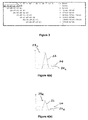
- a convolution is operated on the first data set i tr (n) of signal characteristics, with the coefficients inserting a zero between respective iterations, i.e. as shown in Figure 3 .
- the interpolation step is repeated until the desired equivalent sampling frequency is achieved.
- the equivalent sampling frequency would be 200 kHz after one interpolation step, 400 kHz after two interpolation steps, 800 kHz after three interpolation steps, and 1.6 MHz after four interpolation steps.
- Step (c) of the first embodiment of the invention i.e. the step of identifying a fault wave signal 22 within the second data set i trH (n), includes identifying when a signal characteristic within the second data set i trH (n) exceeds a fault threshold 24.
- the fault threshold 24 is selected to be greater than a 5% value 26 L , 26 R of a corresponding peak value signal characteristic 28 L , 28 R .
- identifying when a signal characteristic within the second data set i trH (n) exceeds a fault threshold 24 also includes establishing the time t L , t R that the fault threshold 24 is exceeded, i.e. the time t L , t R at which the fault wave signal 22 is received at the respective local or remote end 16, 18 of the phase lines 14A, 14B, 14C, as illustrated schematically with respect to the local end 16 in Figure 4(a) , and in Figure 4(b) with respect to the remote end 18.
- step (d) of utilising the propagation characteristics of the fault wave signal 22 to determine the origin of the fault wave signal 22 within the power transmission conduit 10, i.e. to determine the location of the fault 20, includes
Landscapes
- Physics & Mathematics (AREA)
- General Physics & Mathematics (AREA)
- Engineering & Computer Science (AREA)
- Mathematical Physics (AREA)
- Theoretical Computer Science (AREA)
- Locating Faults (AREA)
Abstract
Description
- This invention relates to a method of determining a fault location in a power transmission conduit.
- The accurate location of faults within a power transmission network saves time and resources for network operators.
- Line searches, i.e. a visual inspection of power transmission conduits, are costly and can be inconclusive. In addition, in the case of an underground cable they may not even be practicable.
- Two other methods of fault location, i.e. a so-called impedance based method and a so-called travelling wave based method, tend therefore to be used instead. The travelling wave based method is generally considered to be more accurate.
- According to a first embodiment of the invention there is provided a method of determining a fault location in a power transmission conduit comprising the steps of:
- (a) sampling at an original sampling frequency a signal propagating through the power transmission conduit to establish a first data set including a plurality of sampled signal characteristics;
- (b) interpolating the first data set to establish a second data set including an increased number of signal characteristics whereby the second data set has an equivalent sampling frequency higher than the original sampling frequency;
- (c) identifying a fault wave signal within the second data set; and
- (d) utilising the propagation characteristics of the fault wave signal to determine the origin of the fault wave signal within the power transmission conduit.
- The ability to sample a signal travelling through a power transmission conduit at an original sampling frequency that is lower than the equivalent sampling frequency of the second data set reduces the cost of the sampling equipment required, and so helps to reduce the overall cost of the associated fault locator equipment.
- Meanwhile the step of interpolating the first data set to establish a second data set with an equivalent sampling frequency higher than the original sampling frequency, i.e. a second data set with a higher resolution than the first data set, helps to ensure that the invention is able to determine a fault location with the same degree of accuracy as more expensive fault locator assemblies which are configured to sample at much higher sampling frequencies.
- Preferably step (a) of sampling at an original sampling frequency a signal propagating through the power transmission conduit includes filtering the first data set.
- Optionally filtering the first data set includes applying a band pass filter to one of:
- the signal; or
- the first data set.
- Such filtering advantageously helps to focus the first data set on the likely signal characteristics of a fault wave signal which arise when a fault occurs in the power transmission conduit.
- The band pass filter may have a lower frequency limit of between 2 kHz and 10 kHz.
- Such a lower frequency limit assists in removing low frequency components from the first data set and so helps to ensure accurate and efficient capture of fault wave signals.
- The band pass filter may have an upper frequency limit not more than half the original sampling frequency.
- Having such an upper frequency limit helps to prevent aliasing, i.e. distortion, of the signal represented by the first data set.
- In a preferred method of the invention in which step (a) includes sampling at an original sampling frequency each of a respective phase signal propagating through a corresponding one of a plurality of phase conduits of a power transmission conduit configured to transfer power within a multi-phase power transmission network to establish a plurality of individual phase data sets including a plurality of sample phase signal characteristics, the method thereafter includes converting the plurality of individual phase data sets into a single first data set indicative of the said individual phase data sets.
- Optionally converting the plurality of individual phase data sets into a single first data set includes converting the phase data sets into a mode domain.
- Preferably the manner in which conversion into the mode domain occurs is dependent on the nature of a fault arising with respect to one or more of the phase conduits.
- The foregoing steps of the method of the invention helpfully assist in applying the method of the invention to a power transmission conduit within a multi-phase power transmission network.
- In another preferred embodiment of the method of the invention step (b) of interpolating the first data set to establish a second data set including an increased number of signal characteristics is such that the second data set has an equivalent sampling frequency that is at least five times higher than the original sampling frequency.
- Such interpolation of the first data set helps to ensure a worthwhile reduction in the sampling capability needed by the or each equipment item carrying out sampling of a signal, and hence helps to ensure a commensurate reduction in the capital equipment cost of the or each said equipment item.
- Step (c) of identifying a fault wave signal within the second data set may include identifying when a signal characteristic within the second data set exceeds a fault threshold.
- Such a step is readily repeatable and reliably identifies a fault wave signal.
- Optionally identifying when a signal characteristic within the second data set exceeds a fault threshold includes establishing the time at which the fault threshold is exceeded.
- The foregoing step usefully establishes data that permits the subsequent determination of a distance identifying the location of a fault within the power transmission conduit.
- In a still further preferred embodiment of the invention step (d) of utilising the propagation characteristics of the fault wave signal to determine the origin of the fault wave signal within the power transmission conduit includes:
- carrying out steps (a) to (c) at each of a local end of the transmission conduit and a remote end of the transmission conduit to thereby establish the respective time at which a corresponding fault threshold is exceeded at each of the said local and remote ends; and thereafter;
- determining the distance of the fault from the local end according to:

- m is the distance of the fault from the local end;
- L is the total length of the power transmission conduit;
- tL is the time at which a fault threshold is exceeded at the local end;
- tR is the time at which a fault threshold is exceeded at the remote end; and
- v is the propagation velocity of the fault wave signal.
- Such steps desirably make use of available data to accurately and reliably determine the distance of the fault from the local end of the power transmission conduit, i.e. the fault location within the power transmission conduit.
- There now follows a brief description of preferred embodiments of the invention, by way of non-limiting examples, with reference being made to the following figures in which:
-
Figure 1 shows a schematic view of a power transmission conduit; -
Figure 2 illustrates schematically principle steps in a method of determining a fault location, in the power transmission conduit shown inFigure 1 , according to a first embodiment of the invention; -
Figure 3 illustrates the impact, within the method illustrated inFigure 2 , of respective iterations on a first data set; and -
Figures 4(a) and 4(b) illustrate schematically the step, within the method illustrated inFigure 2 , of identifying when a signal characteristic exceeds a fault threshold. - An example
power transmission conduit 10, which forms a part of a multi-phasepower transmission network 12, is illustrated schematically inFigure 1 . - In the example shown, the
power transmission conduit 10 is an overhead transmission line 14 which includes three phase conduits, i.e. threephase lines power transmission network 12. - The method of the invention is equally applicable to power transmission conduits which take the form of, e.g. an underground transmission cable, and/or include fewer than or more than three phase conduits.
- The power transmission conduit 10, i.e. the
respective phase lines local end 16 and aremote end 18. - A method, according to a first embodiment of the invention, of determining a fault location within the example
power transmission conduit 10, i.e. the location of a fault 20 with respect to one or more of therespective phase lines Figure 2 , the principle steps of: - (a) sampling at an original sampling frequency a signal propagating through the
power transmission conduit 10 to establish a first data set which includes a plurality of sampled signal characteristics; - (b) interpolating the first data set to establish a second data set that includes an increased number of signal characteristics whereby the second data set has an equivalent sampling frequency which is higher than the original sampling frequency;
- (c) identifying a fault wave signal within the second data set; and
- (d) utilising the propagation characteristics of the fault wave signal to determine the origin of the fault wave signal within the
power transmission conduit 10. - More particularly, sampling a signal propagating through the
power transmission conduit 10 includes, first of all measuring a respective current signal iA(t), iB(t), ic(t) within eachphase line - In other embodiment of the invention, sampling a signal propagating through the power transmission conduit may instead include measuring one or more respective voltage signals within the or each phase line, conduit or cable.
- Returning to the embodiment of the method illustrated schematically in
Figure 2 , the sampling step (a) also includes applying a band pass filter to each current signal iA(t), iB(t), iC(t). - The band pass filter has a lower frequency limit of 10 kHz, although in other embodiments of the invention the lower frequency limit may lie between 2 kHz and 10 kHz.
- The upper frequency of the band pass filter is preferably not more than half the original sampling frequency. The original sampling frequency preferably is not less than 96 kHz and by way of example is, in the embodiment described, 100 kHz although it may vary in other embodiments of the invention.
- More preferably still, in the embodiment of the invention described herein above, the upper frequency of the band pass filter is one quarter of the original sampling frequency, i.e. is 25 kHz.
- Following such filtering of the respective current signals iA(t), iB(t), ic(t) an analogue to digital sampling module obtains samples of the said current signals iA(t), iB(t), ic(t) at the original sampling frequency, e.g. 100 kHz, to establish three individual corresponding phase data sets iA, iB, iC, each of which includes a plurality of sample phase current signal characteristics.
- Step (a) of the method then further includes converting the individual phase data sets iA, iB, iC into a single first data set itr(n) which is indicative of the said individual phase data sets iA, iB, iC.
- Such conversion into a single first data set itr(n) includes converting the phase data sets iA, iB, iC into a mode domain, and more particularly the manner in which the conversion takes place is dependent on the nature of fault 20 arising with respect to one or more of the phase conduits, i.e. with respect to one or more of the
phase lines - If the fault 20 arises:
- between the phase
A phase line 14A and ground (as illustrated by way of example inFigure 1 ) then the single first data set itr(n) is given by
- between the phase
B phase line 14B and ground then the single first data set itr(n) is given by
- between the phase
C phase line 14C and ground then the single first data set itr(n) is given by
- between the phase
A phase line 14A and the phaseB phase line 14B (whether grounded or ungrounded) then the single first data set itr(n) is given by
- between the phase
B phase line 14B and the phaseC phase line 14C (whether grounded or ungrounded) then the single first data set itr(n) is given by
- between the phase
C phase line 14C and the phaseA phase line 14A (whether grounded or ungrounded) then the single first data set itr(n) is given by
- between all
phase lines 
- In other embodiments of the method of the invention, the first data set, whether converted from a plurality of individual phase data sets or not, may instead be filtered by first of all sampling a signal, e.g. using a current or voltage transformer as appropriate, and then applying a band pass filter to the sampled signal characteristics. Following step (a) as described hereinabove, step (b) of the first embodiment method of the invention includes interpolating the first data set itr(n) to establish a second data set itrH(n) which includes an increased number of signal characteristics such that the second data set itrH(n) has an equivalent sampling frequency that is at least five times higher than the original sampling frequency.
- By way of example, the first data set itr(n) is interpolated so that it has an equivalent sampling frequency of 1.6 MHz which is sixteen times higher than the original sampling frequency of 100 Hz.
- One way in which the first data set itr(n) may be interpolated, although other techniques are also possible within the scope of the invention, is to use M-order spline interpolation.
- Such interpolation includes selecting a proper order for the spline function, and then calculating coefficients for interpolation using the following formula,

M = 1, 2, 3 or 4 , ...; and
- For example, if we select M = 5, then the coefficients for interpolation are:


- Once the coefficients for interpolation have been established, interpolation is carried out according to

- In other words, a convolution is operated on the first data set itr(n) of signal characteristics, with the coefficients inserting a zero between respective iterations, i.e. as shown in
Figure 3 . - Thereafter the interpolation step is repeated until the desired equivalent sampling frequency is achieved. For example, for an original sampling frequency of 100 kHz, the equivalent sampling frequency would be 200 kHz after one interpolation step, 400 kHz after two interpolation steps, 800 kHz after three interpolation steps, and 1.6 MHz after four interpolation steps.
- Step (c) of the first embodiment of the invention, i.e. the step of identifying a
fault wave signal 22 within the second data set itrH(n), includes identifying when a signal characteristic within the second data set itrH(n) exceeds afault threshold 24. Preferably thefault threshold 24 is selected to be greater than a 5% value - In addition, identifying when a signal characteristic within the second data set itrH(n) exceeds a
fault threshold 24 also includes establishing the time tL, tR that thefault threshold 24 is exceeded, i.e. the time tL , tR at which thefault wave signal 22 is received at the respective local orremote end phase lines local end 16 inFigure 4(a) , and inFigure 4(b) with respect to theremote end 18. - Thereafter step (d) of utilising the propagation characteristics of the
fault wave signal 22 to determine the origin of thefault wave signal 22 within thepower transmission conduit 10, i.e. to determine the location of the fault 20, includes - carrying out steps (a) to (c) at each of the
local end 16 and theremote end 18 of thetransmission conduit 10 to thereby establish the respective time tL, tR at which thecorresponding fault threshold 24 is exceeded at a corresponding one of each of the said local and remote ends 16, 18; and thereafter - determining the distance of the fault 20 from the
local end 16 according to:
- m is the distance of the fault 20 from the
local end 16; - L is the total length of the
power transmission conduit 10; and - v is the propagation velocity of the
fault wave signal 22.
- m is the distance of the fault 20 from the
- Other ways of utilising the propagation characteristics of the
fault wave signal 22 to determine the origin of thefault wave signal 22 within thepower transmission conduit 10, i.e. to determine the location of the fault 20, are also possible within the scope of the invention.
Claims (12)
- A method of determining a fault location (20) in a power transmission conduit (10) comprising the steps of:(a) sampling at an original sampling frequency a signal (iA(t), iB(t), ic(t)) propagating through the power transmission conduit (10) to establish a first data set (itr(n)) including a plurality of sampled signal characteristics;(b) interpolating the first data set (itr(n)) to establish a second data set (itrH(n)) including an increased number of signal characteristics whereby the second data set (itrH(n)) has an equivalent sampling frequency higher than the original sampling frequency;(c) identifying a fault wave signal (22) within the second data set (itrH(n)); and(d) utilising the propagation characteristics of the fault wave signal (22) to determine the origin of the fault wave signal (22) within the power transmission conduit (10).
- A method according to Claim 1, wherein step (a) of sampling at an original sampling frequency a signal (iA(t), iB(t), ic(t)) propagating through the power transmission conduit (10) includes filtering the first data set (itr(n)).
- A method according to Claim 2, wherein filtering the first data set (itr(n)) includes applying a band pass filter to one of:the signal (iA(t), iB(t), ic(t)); orthe first data set (itr(n)).
- A method according to Claim 3, wherein the band pass filter has a lower frequency limit of between 2 kHz and 10 kHz.
- A method according to Claim 3 or Claim 4, wherein the band pass filter has an upper frequency limit not more than half the original sampling frequency.
- A method according to any preceding claim ,wherein step (a) includes sampling at an original sampling frequency each of a respective phase signal (iA(t), iB(t), ic(t)) propagating through a corresponding one of a plurality of phase conduits (14A, 14B, 14C) of a power transmission conduit (10) configured to transfer power within a multi-phase power transmission network (12) to establish a plurality of individual phase data sets (iA, iB, iC) including a plurality of sample phase signal characteristics, and thereafter converting the plurality of individual phase data sets (iA, iB, iC) into a single first data set (itr(n)) indicative of the said individual phase data sets (iA, iB, iC).
- A method according to Claim 6, wherein converting the plurality of individual phase data sets (iA, iB, iC) into a single first data set (itr(n)) includes converting the phase data sets (iA, iB, iC) into a mode domain.
- A method according to Claim 7, wherein the manner in which conversion into the mode domain occurs is dependent on the nature of a fault (20) arising with respect to one or more of the phase conduits (14A, 14B, 14C).
- A method according to any preceding claim, wherein step (b) of interpolating the first data set (itr(n)) to establish a second data set (itrH(n)) including an increased number of signal characteristics is such that the second data set (itrH(n)) has an equivalent sampling frequency that is at least five times higher than the original sampling frequency.
- A method according to any preceding claim, wherein step (c) of identifying a fault wave signal (22) within the second data set (itrH(n)) includes identifying when a signal characteristic within the second data set (itrH(n)) exceeds a fault threshold (24).
- A method according to Claim 10, wherein identifying when a signal characteristic within the second data set (itrH(n)) exceeds a fault threshold (24) includes establishing the time (tL, tR) at which the fault threshold (24) is exceeded.
- A method according to Claim 11, wherein step (d) of utilising the propagation characteristics of the fault wave signal (22) to determine the origin of the fault wave signa (22)1 within the power transmission conduit (10) includes:carrying out steps (a) to (c) at each of a local end (16) of the transmission conduit (10) and a remote end (18) of the transmission conduit (10) to thereby establish the respective time (tL, tR) at which a corresponding fault threshold (24) is exceeded at each of the said local and remote ends (16, 18); and thereafter;determining the distance of the fault (20) from the local end (16) according to:
 m is the distance of the fault (20) from the local end (16);L is the total length of the power transmission conduit (10);tL is the time at which a fault threshold (24) is exceeded at the local end (16);tR is the time at which a fault threshold (24) is exceeded at the remote end (18); andv is the propagation velocity of the fault wave signal (22).
Priority Applications (8)
| Application Number | Priority Date | Filing Date | Title |
|---|---|---|---|
| EP16184529.2A EP3285078A1 (en) | 2016-08-17 | 2016-08-17 | Improvements in or relating to locating faults in power transmission conduits |
| PCT/EP2017/070080 WO2018033436A1 (en) | 2016-08-17 | 2017-08-08 | Improvements in or relating to locating faults in power transmission conduits |
| CA3033089A CA3033089A1 (en) | 2016-08-17 | 2017-08-08 | Improvements in or relating to locating faults in power transmission conduits |
| BR112019003152-9A BR112019003152B1 (en) | 2016-08-17 | 2017-08-08 | METHOD FOR DETERMINING A FAULT LOCATION IN A POWER TRANSMISSION CONDUIT |
| JP2019507918A JP2019526791A (en) | 2016-08-17 | 2017-08-08 | Improvements in or related to fault location in transmission lines |
| CN201780050242.3A CN109564258A (en) | 2016-08-17 | 2017-08-08 | About or being located in improvement in the failure in power transmission pipeline |
| MX2019001909A MX2019001909A (en) | 2016-08-17 | 2017-08-08 | Improvements in or relating to locating faults in power transmission conduits. |
| US16/325,982 US11474140B2 (en) | 2016-08-17 | 2017-08-08 | Relating to locating faults in power transmission conduits |
Applications Claiming Priority (1)
| Application Number | Priority Date | Filing Date | Title |
|---|---|---|---|
| EP16184529.2A EP3285078A1 (en) | 2016-08-17 | 2016-08-17 | Improvements in or relating to locating faults in power transmission conduits |
Publications (1)
| Publication Number | Publication Date |
|---|---|
| EP3285078A1 true EP3285078A1 (en) | 2018-02-21 |
Family
ID=56799266
Family Applications (1)
| Application Number | Title | Priority Date | Filing Date |
|---|---|---|---|
| EP16184529.2A Withdrawn EP3285078A1 (en) | 2016-08-17 | 2016-08-17 | Improvements in or relating to locating faults in power transmission conduits |
Country Status (7)
| Country | Link |
|---|---|
| US (1) | US11474140B2 (en) |
| EP (1) | EP3285078A1 (en) |
| JP (1) | JP2019526791A (en) |
| CN (1) | CN109564258A (en) |
| CA (1) | CA3033089A1 (en) |
| MX (1) | MX2019001909A (en) |
| WO (1) | WO2018033436A1 (en) |
Cited By (2)
| Publication number | Priority date | Publication date | Assignee | Title |
|---|---|---|---|---|
| CN111521905A (en) * | 2020-03-30 | 2020-08-11 | 国网上海市电力公司 | Power grid fault diagnosis method based on intelligent fusion of multi-dimensional data fault degrees |
| US11424613B2 (en) | 2019-03-05 | 2022-08-23 | General Electric Technology Gmbh | Universal traveling-wave-based protection and fault location for power system |
Families Citing this family (1)
| Publication number | Priority date | Publication date | Assignee | Title |
|---|---|---|---|---|
| FR3134455B1 (en) * | 2022-04-12 | 2024-04-05 | Commissariat Energie Atomique | Method and device for analyzing defects by reflectometry using transfer function estimation |
Citations (6)
| Publication number | Priority date | Publication date | Assignee | Title |
|---|---|---|---|---|
| EP0882993A2 (en) * | 1997-06-02 | 1998-12-09 | Tektronix, Inc. | Apparatus for acquiring waveform data from a metallic transmission cable |
| US20020169585A1 (en) * | 2001-03-16 | 2002-11-14 | Jones Keith R. | Adaptive method and apparatus for transmission line analysis |
| WO2005109020A2 (en) * | 2004-05-06 | 2005-11-17 | University Of Utah Research Foundation | System and method for characterizing a signal path using a sub-chip sampler |
| US20090315565A1 (en) * | 2008-06-19 | 2009-12-24 | Acterna Llc | Adaptive pulse width time domain reflectometer |
| EP2490031A1 (en) * | 2011-02-15 | 2012-08-22 | ABB Technology AG | Method and system for measuring an electrical quantity in an electrical network |
| WO2015039114A1 (en) * | 2013-09-16 | 2015-03-19 | Schweitzer Engineering Laboratories, Inc | Traveling wave validation using estimated fault location |
Family Cites Families (24)
| Publication number | Priority date | Publication date | Assignee | Title |
|---|---|---|---|---|
| US4695825A (en) * | 1986-04-28 | 1987-09-22 | Metme Communications | Analog-digital conversion system |
| SE507043C2 (en) * | 1996-08-29 | 1998-03-16 | Asea Brown Boveri | Measurement procedure at line error locator on HVDC lines |
| TW475991B (en) * | 1998-12-28 | 2002-02-11 | Nippon Kouatsu Electric Co Ltd | Fault point location system |
| JP4044489B2 (en) * | 2002-06-06 | 2008-02-06 | 東京電力株式会社 | Fault location method for power transmission lines and fault location system using the same |
| JP4392232B2 (en) * | 2002-12-13 | 2009-12-24 | 日本鉄塔工業株式会社 | Film thickness measurement method |
| EP2014899B8 (en) | 2003-11-12 | 2013-02-20 | Toyota Jidosha Kabushiki Kaisha | Fuel injection control apparatus and fuel injection control method for internal combustion engine |
| CN100583590C (en) * | 2007-08-03 | 2010-01-20 | 西安交通大学 | Integrated failure positioning protection system for transfer line |
| CN101299538B (en) * | 2008-04-08 | 2011-01-12 | 昆明理工大学 | Cable-aerial mixed line fault travelling wave ranging method |
| US8373570B2 (en) * | 2010-10-26 | 2013-02-12 | Cooper Technologies Company | ARC fault detection method and apparatus |
| CN103209646B (en) * | 2010-11-18 | 2015-09-09 | 皇家飞利浦电子股份有限公司 | For the filter apparatus to ultrasonic signal filtering |
| CN102305900A (en) * | 2011-05-21 | 2012-01-04 | 山东大学 | Travelling wave fault ranging method and device based on differential output of Rogowski coil |
| CA2780402A1 (en) * | 2011-06-20 | 2012-12-20 | Erlphase Power Technologies Limited | Power system fault zone detection |
| CA2850834C (en) * | 2011-10-12 | 2015-12-29 | Schweitzer Engineering Laboratories, Inc. | Fault location using traveling waves |
| CN102998593B (en) | 2012-11-15 | 2015-04-15 | 华北电力大学 | Method for accurately positioning electrical cable faults through interpolation convolution calculating |
| CN103293449B (en) | 2012-12-31 | 2015-04-29 | 中国矿业大学 | Method for removing single-terminal traveling wave fault location dead area of high-voltage power grid in coal mine |
| US20150316593A1 (en) * | 2013-03-15 | 2015-11-05 | Mitsubishi Electric Corporation | Merging unit which collects information of power system |
| US8990036B1 (en) | 2013-09-16 | 2015-03-24 | Schweitzer Engineering Laboratories, Inc. | Power line parameter adjustment and fault location using traveling waves |
| US20150081235A1 (en) | 2013-09-16 | 2015-03-19 | Schweitzer Engineering Laboratories, Inc. | Fault location using traveling waves by calculating traveling wave arrival time |
| CN103472361B (en) * | 2013-09-18 | 2016-08-17 | 上海申贝科技发展有限公司 | Based on Spatial Signal Detection and the transmission open acess system of high accuracy time service |
| CN103941150B (en) * | 2014-04-03 | 2017-07-07 | 昆明理工大学 | It is a kind of merely with voltage be independent of both-end it is synchronous zero, line mould time difference radiation network fault positioning method |
| CN103969554A (en) * | 2014-05-30 | 2014-08-06 | 智友光电技术发展有限公司 | Online failure positioning device for high voltage cable line and positioning method thereof |
| CN105301447B (en) * | 2015-11-10 | 2018-08-17 | 上海交通大学 | Flexible direct current power transmission system cable monopole fault distance-finding method |
| CN205404670U (en) * | 2016-02-18 | 2016-07-27 | 四川中光防雷科技股份有限公司 | Transmission line transient state current collection device |
| WO2017218558A1 (en) * | 2016-06-14 | 2017-12-21 | Schweitzer Engineering Laboratories, Inc. | Phase selection for traveling wave fault detection systems |
-
2016
- 2016-08-17 EP EP16184529.2A patent/EP3285078A1/en not_active Withdrawn
-
2017
- 2017-08-08 JP JP2019507918A patent/JP2019526791A/en active Pending
- 2017-08-08 CN CN201780050242.3A patent/CN109564258A/en active Pending
- 2017-08-08 CA CA3033089A patent/CA3033089A1/en not_active Abandoned
- 2017-08-08 US US16/325,982 patent/US11474140B2/en active Active
- 2017-08-08 MX MX2019001909A patent/MX2019001909A/en unknown
- 2017-08-08 WO PCT/EP2017/070080 patent/WO2018033436A1/en active Application Filing
Patent Citations (6)
| Publication number | Priority date | Publication date | Assignee | Title |
|---|---|---|---|---|
| EP0882993A2 (en) * | 1997-06-02 | 1998-12-09 | Tektronix, Inc. | Apparatus for acquiring waveform data from a metallic transmission cable |
| US20020169585A1 (en) * | 2001-03-16 | 2002-11-14 | Jones Keith R. | Adaptive method and apparatus for transmission line analysis |
| WO2005109020A2 (en) * | 2004-05-06 | 2005-11-17 | University Of Utah Research Foundation | System and method for characterizing a signal path using a sub-chip sampler |
| US20090315565A1 (en) * | 2008-06-19 | 2009-12-24 | Acterna Llc | Adaptive pulse width time domain reflectometer |
| EP2490031A1 (en) * | 2011-02-15 | 2012-08-22 | ABB Technology AG | Method and system for measuring an electrical quantity in an electrical network |
| WO2015039114A1 (en) * | 2013-09-16 | 2015-03-19 | Schweitzer Engineering Laboratories, Inc | Traveling wave validation using estimated fault location |
Cited By (2)
| Publication number | Priority date | Publication date | Assignee | Title |
|---|---|---|---|---|
| US11424613B2 (en) | 2019-03-05 | 2022-08-23 | General Electric Technology Gmbh | Universal traveling-wave-based protection and fault location for power system |
| CN111521905A (en) * | 2020-03-30 | 2020-08-11 | 国网上海市电力公司 | Power grid fault diagnosis method based on intelligent fusion of multi-dimensional data fault degrees |
Also Published As
| Publication number | Publication date |
|---|---|
| US11474140B2 (en) | 2022-10-18 |
| US20190178929A1 (en) | 2019-06-13 |
| MX2019001909A (en) | 2019-05-15 |
| BR112019003152A2 (en) | 2019-05-21 |
| CA3033089A1 (en) | 2018-02-22 |
| JP2019526791A (en) | 2019-09-19 |
| WO2018033436A1 (en) | 2018-02-22 |
| CN109564258A (en) | 2019-04-02 |
Similar Documents
| Publication | Publication Date | Title |
|---|---|---|
| US10746779B2 (en) | Fault location detection and distance protection apparatus and associated method | |
| US11474140B2 (en) | Relating to locating faults in power transmission conduits | |
| US9453871B2 (en) | Fault location on a de-energized power line section | |
| US10727666B2 (en) | Relating to direct current protection schemes | |
| KR100978902B1 (en) | Method and apparatus for estimating a phasor based on fourier transform to eliminate the adverse influence of the exponentially decaying dc offsets | |
| KR100580428B1 (en) | A compensation method for the distorted secondary current of a current transformer | |
| EP3482472B1 (en) | A method and system for locating a fault in a mixed power transmission line | |
| CN101201282A (en) | Fundamental frequency identification method for detecting cord force of cable-stayed bridge | |
| Dashtdar et al. | Fault location in the transmission network using a discrete wavelet transform | |
| US20200400734A1 (en) | Parameter Free Traveling Wave Based Fault Location for Power Transmission Lines | |
| CN104931793B (en) | A kind of grounding net of transformer substation impedance ground acquisition methods | |
| US20100010761A1 (en) | Method and device for monitoring a system | |
| Dashtdar et al. | Fault location in the transmission network based on extraction of fault components using wavelet transform | |
| CN108828398B (en) | Single-core cable partial discharge positioning method based on structural similarity algorithm | |
| EP0805355A3 (en) | Procedure and apparatus for determining the distance to a cable fault | |
| US20050063323A1 (en) | Method and circuit arrangement for determination of transmission parameters | |
| EP3499732B1 (en) | Test arrangement, device and method for measuring a directed signal | |
| Mangalge et al. | Location of fault in long HVDC transmission line using continuous wavelet transform | |
| Barrera et al. | Waveform segmentation for intelligent monitoring of power events | |
| Prabhavathi et al. | Detection and location of faults in 11kv underground cable by using continuous wavelet transform (cwt) | |
| Maier et al. | Improvement of the line-resonance-analysis with several mathematical-detection-algorithms and filters | |
| CN113064103B (en) | Secondary cable identification method and device based on asymmetric phase signals | |
| Nagata et al. | Data processing of magnetotelluric survey data in time domain using digital filter-An Example at the Nankai trough | |
| El Haffar et al. | Evaluation of travelling wave fault location methods based on field measurements | |
| Siew et al. | Automatic fault location for underground distribution network |
Legal Events
| Date | Code | Title | Description |
|---|---|---|---|
| PUAI | Public reference made under article 153(3) epc to a published international application that has entered the european phase |
Free format text: ORIGINAL CODE: 0009012 |
|
| AK | Designated contracting states |
Kind code of ref document: A1 Designated state(s): AL AT BE BG CH CY CZ DE DK EE ES FI FR GB GR HR HU IE IS IT LI LT LU LV MC MK MT NL NO PL PT RO RS SE SI SK SM TR |
|
| AX | Request for extension of the european patent |
Extension state: BA ME |
|
| 17P | Request for examination filed |
Effective date: 20180821 |
|
| RBV | Designated contracting states (corrected) |
Designated state(s): AL AT BE BG CH CY CZ DE DK EE ES FI FR GB GR HR HU IE IS IT LI LT LU LV MC MK MT NL NO PL PT RO RS SE SI SK SM TR |
|
| STAA | Information on the status of an ep patent application or granted ep patent |
Free format text: STATUS: THE APPLICATION IS DEEMED TO BE WITHDRAWN |
|
| 18D | Application deemed to be withdrawn |
Effective date: 20180822 |