EP3283429B1 - A lifting vehicle incorporating a load monitor - Google Patents
A lifting vehicle incorporating a load monitor Download PDFInfo
- Publication number
- EP3283429B1 EP3283429B1 EP16717676.7A EP16717676A EP3283429B1 EP 3283429 B1 EP3283429 B1 EP 3283429B1 EP 16717676 A EP16717676 A EP 16717676A EP 3283429 B1 EP3283429 B1 EP 3283429B1
- Authority
- EP
- European Patent Office
- Prior art keywords
- vehicle
- mast
- chassis
- strain gauge
- bridge
- Prior art date
- Legal status (The legal status is an assumption and is not a legal conclusion. Google has not performed a legal analysis and makes no representation as to the accuracy of the status listed.)
- Active
Links
Images


Classifications
-
- B—PERFORMING OPERATIONS; TRANSPORTING
- B66—HOISTING; LIFTING; HAULING
- B66F—HOISTING, LIFTING, HAULING OR PUSHING, NOT OTHERWISE PROVIDED FOR, e.g. DEVICES WHICH APPLY A LIFTING OR PUSHING FORCE DIRECTLY TO THE SURFACE OF A LOAD
- B66F17/00—Safety devices, e.g. for limiting or indicating lifting force
- B66F17/003—Safety devices, e.g. for limiting or indicating lifting force for fork-lift trucks
-
- B—PERFORMING OPERATIONS; TRANSPORTING
- B66—HOISTING; LIFTING; HAULING
- B66F—HOISTING, LIFTING, HAULING OR PUSHING, NOT OTHERWISE PROVIDED FOR, e.g. DEVICES WHICH APPLY A LIFTING OR PUSHING FORCE DIRECTLY TO THE SURFACE OF A LOAD
- B66F9/00—Devices for lifting or lowering bulky or heavy goods for loading or unloading purposes
- B66F9/06—Devices for lifting or lowering bulky or heavy goods for loading or unloading purposes movable, with their loads, on wheels or the like, e.g. fork-lift trucks
- B66F9/07—Floor-to-roof stacking devices, e.g. "stacker cranes", "retrievers"
-
- B—PERFORMING OPERATIONS; TRANSPORTING
- B66—HOISTING; LIFTING; HAULING
- B66F—HOISTING, LIFTING, HAULING OR PUSHING, NOT OTHERWISE PROVIDED FOR, e.g. DEVICES WHICH APPLY A LIFTING OR PUSHING FORCE DIRECTLY TO THE SURFACE OF A LOAD
- B66F9/00—Devices for lifting or lowering bulky or heavy goods for loading or unloading purposes
- B66F9/06—Devices for lifting or lowering bulky or heavy goods for loading or unloading purposes movable, with their loads, on wheels or the like, e.g. fork-lift trucks
- B66F9/075—Constructional features or details
- B66F9/0755—Position control; Position detectors
-
- B—PERFORMING OPERATIONS; TRANSPORTING
- B66—HOISTING; LIFTING; HAULING
- B66F—HOISTING, LIFTING, HAULING OR PUSHING, NOT OTHERWISE PROVIDED FOR, e.g. DEVICES WHICH APPLY A LIFTING OR PUSHING FORCE DIRECTLY TO THE SURFACE OF A LOAD
- B66F9/00—Devices for lifting or lowering bulky or heavy goods for loading or unloading purposes
- B66F9/06—Devices for lifting or lowering bulky or heavy goods for loading or unloading purposes movable, with their loads, on wheels or the like, e.g. fork-lift trucks
- B66F9/075—Constructional features or details
- B66F9/08—Masts; Guides; Chains
- B66F9/082—Masts; Guides; Chains inclinable
-
- B—PERFORMING OPERATIONS; TRANSPORTING
- B66—HOISTING; LIFTING; HAULING
- B66F—HOISTING, LIFTING, HAULING OR PUSHING, NOT OTHERWISE PROVIDED FOR, e.g. DEVICES WHICH APPLY A LIFTING OR PUSHING FORCE DIRECTLY TO THE SURFACE OF A LOAD
- B66F9/00—Devices for lifting or lowering bulky or heavy goods for loading or unloading purposes
- B66F9/06—Devices for lifting or lowering bulky or heavy goods for loading or unloading purposes movable, with their loads, on wheels or the like, e.g. fork-lift trucks
- B66F9/075—Constructional features or details
- B66F9/12—Platforms; Forks; Other load supporting or gripping members
- B66F9/122—Platforms; Forks; Other load supporting or gripping members longitudinally movable
-
- B—PERFORMING OPERATIONS; TRANSPORTING
- B66—HOISTING; LIFTING; HAULING
- B66F—HOISTING, LIFTING, HAULING OR PUSHING, NOT OTHERWISE PROVIDED FOR, e.g. DEVICES WHICH APPLY A LIFTING OR PUSHING FORCE DIRECTLY TO THE SURFACE OF A LOAD
- B66F9/00—Devices for lifting or lowering bulky or heavy goods for loading or unloading purposes
- B66F9/06—Devices for lifting or lowering bulky or heavy goods for loading or unloading purposes movable, with their loads, on wheels or the like, e.g. fork-lift trucks
- B66F9/075—Constructional features or details
- B66F9/20—Means for actuating or controlling masts, platforms, or forks
- B66F9/22—Hydraulic devices or systems
-
- G—PHYSICS
- G01—MEASURING; TESTING
- G01G—WEIGHING
- G01G19/00—Weighing apparatus or methods adapted for special purposes not provided for in the preceding groups
- G01G19/08—Weighing apparatus or methods adapted for special purposes not provided for in the preceding groups for incorporation in vehicles
- G01G19/12—Weighing apparatus or methods adapted for special purposes not provided for in the preceding groups for incorporation in vehicles having electrical weight-sensitive devices
-
- G—PHYSICS
- G01—MEASURING; TESTING
- G01L—MEASURING FORCE, STRESS, TORQUE, WORK, MECHANICAL POWER, MECHANICAL EFFICIENCY, OR FLUID PRESSURE
- G01L1/00—Measuring force or stress, in general
- G01L1/20—Measuring force or stress, in general by measuring variations in ohmic resistance of solid materials or of electrically-conductive fluids; by making use of electrokinetic cells, i.e. liquid-containing cells wherein an electrical potential is produced or varied upon the application of stress
- G01L1/22—Measuring force or stress, in general by measuring variations in ohmic resistance of solid materials or of electrically-conductive fluids; by making use of electrokinetic cells, i.e. liquid-containing cells wherein an electrical potential is produced or varied upon the application of stress using resistance strain gauges
- G01L1/225—Measuring circuits therefor
- G01L1/2262—Measuring circuits therefor involving simple electrical bridges
-
- G—PHYSICS
- G07—CHECKING-DEVICES
- G07C—TIME OR ATTENDANCE REGISTERS; REGISTERING OR INDICATING THE WORKING OF MACHINES; GENERATING RANDOM NUMBERS; VOTING OR LOTTERY APPARATUS; ARRANGEMENTS, SYSTEMS OR APPARATUS FOR CHECKING NOT PROVIDED FOR ELSEWHERE
- G07C5/00—Registering or indicating the working of vehicles
- G07C5/08—Registering or indicating performance data other than driving, working, idle, or waiting time, with or without registering driving, working, idle or waiting time
- G07C5/0841—Registering performance data
- G07C5/085—Registering performance data using electronic data carriers
-
- G—PHYSICS
- G08—SIGNALLING
- G08B—SIGNALLING OR CALLING SYSTEMS; ORDER TELEGRAPHS; ALARM SYSTEMS
- G08B3/00—Audible signalling systems; Audible personal calling systems
Definitions
- the present invention relates to a lifting vehicle, in particular a forklift truck, that incorporates a load monitor to assist in reduction of the risk of overloading and tip-over accidents occurring.
- the capacity of the vehicle In order to use a lifting vehicle such as a forklift truck safely the capacity of the vehicle needs to be considered at all times.
- the capacity of the vehicle is determined by the weight of the load to be carried, the centre of gravity of the load and its distance from the front face of the lifting platform or forks (the load centre) and the height of the load.
- Conventional lifting vehicles often incorporate a load monitor in their forks or secured to their lifting platform that measures the bending force in the forks or platform caused by the weight of the load. The monitor relays this information to the cab of the vehicle in order that the driver can be alerted when the vehicle is likely to be overloaded.
- JP 2000 044196 A discloses a lifting vehicle comprising: a lifting device movably mounted on a mast secured to a chassis of the vehicle, raising and lowering of the lifting device on the mast being controlled by a lift cylinder and tilting of the mast forward and backward out of a vertical position being controlled by a tilt cylinder that is mounted by fastenings between a part of the chassis and the mast; a load monitor comprising a strain gauge mounted on a bridge, said strain gauge being secured to the axle connecting the attaching part of the tilt cylinder to the chassis; an indicator in communication with the load monitor that can signal an output of the load monitor to an operator of the vehicle.
- GB1510292 describes a load-handling vehicle, fail-safe overload protective system for preventing a load being handled by the vehicle from imparting an excessive tilting moment to the vehicle likely to cause the vehicle to overturn.
- the vehicle comprises a sensor including a plurality of strain gauges that are mounted externally on a tilt anchor pin of a tilt jack used to maintain a mast of the vehicle in a desired upright condition.
- This arrangement has the disadvantage that the sensor measures stresses in the tilt anchor pin, which include torsional and shearing forces created when the vehicle articulates. These forces are not responsible for causing tip-over accidents.
- the sensor changes position as the pins change direction.
- GB1590440 describes a load handling vehicle comprises a split chassis articulated about a vertical axis at a point between the axles of the vehicle and a superstructure with a lifting member cap able of raising a load and placing it at a distance from the vehicle.
- Such vehicles are usually termed articulated forklift trucks.
- This vehicle comprises a strain gauge that is mounted at the vertical pivot connecting the two parts of the chassis in order that strains are detected due to the superstructure and the load.
- An audible and/or visible alarm is operable by the strain gauge mechanism to give warning when the strains are such as to render the vehicle unstable.
- This arrangement again mounts the strain gauge on a pin that is subject to torsional and shearing forces thereby introducing inaccuracies into the measurements taken.
- the strain gauges do not measure stresses in the vehicle chassis or its mast directly and detect torsional and shearing forces that distort the reading of forces that should be measured to determine whether the vehicle is overloaded or liable to tip over.
- a lifting vehicle comprising a lifting device movably mounted on a mast secured to a chassis of the vehicle, raising and lowering of the lifting device on the mast being controlled by a lift cylinder and tilting of the mast forward and backward out of a vertical position being controlled by a tilt cylinder that is mounted by fastenings between a part of the chassis and the mast; a load monitor comprising a strain gauge mounted on a bridge that is secured at each end to locations that are either on said part of the chassis or on the mast adjacent the fastening for the tilt cylinder; and an indicator in communication with the load monitor that can signal an output of the load monitor to an operator of the vehicle; the locations on said part of the chassis or on the mast to which the ends of the bridge are secured being static with respect to one another.
- the load monitor is able to measure the stress being imposed on the chassis or mast of the vehicle directly. This enables not only to the weight of the load to be detected but also the stability of the vehicle as a whole to be determined uncontaminated by directional, torsional or shearing forces. The arrangement is therefore much reliable than conventional arrangements.
- said fastenings are clevis fastenings and the bridge is secured to said part of the chassis or the mast that is adapted to form part of one of said clevis fastenings.
- the bridge is secured to at each end either to said part of the chassis or the mast by studs that are stud welded to said part of the chassis or the mast.
- the strain gauge comprises a resistive strain gauge.
- a lifting vehicle 1 such as a forklift truck as shown in Figs. 1 and 6 comprises a chassis 2 carried by front wheels 3 and rear steering wheels 4. Mounted on the chassis 2 are a cab 5 for an operator and a mast 6.
- a lifting device for example lifting forks 7 or in other embodiments of the invention a lifting platform, is mounted on the mast 6. Raising and lowering of the lifting forks 7 is controlled by a lift cylinder 8 mounted on the mast 6. Tilting of the mast 6 and thereby the lifting forks 7 forward and backward out of a vertical position is controlled by a pair of tilt cylinders 9 located on opposite sides of the mast 6 respectively, each of which cylinders 9 is mounted between a part 10 of the chassis 2 and the mast 6.
- the truck shown in Fig. 6 differs from that shown in Fig. 1 in that it is an articulated forklift truck wherein the chassis 2 is split, a front part 2F carrying the lifting device including the mast 5 and forks 7 is articulated about a vertical axis A to a rear part 2R carrying the cab 5 and counterweight 11.
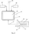
- the moment force is monitored by a load monitor 13 that comprises one and preferably two strain gauges 14 linked to a processor 15 and indicator 16, typically a display screen, by wiring 17 as shown in Fig. 2 .
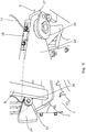
- the strain gauges 14 are preferably resistive strain gauges and are each mounted on a bridge 18 secured at each end to locations that are either on that part 10 of the chassis 2 adjacent the mounting of one end of the tilt cylinders 9, as shown in Figs. 3 and 4 , or alternatively on the mast 6 at positions adjacent to the mounting of the other end of the tilt cylinders 9, as shown in Figs. 5 and 7 .
- These locations, that is those on the part 10 of the chassis 2 or on the mast 6, are static with respect to one another. This is described in more detail below.
- This is a non-destructive mode of attachment that does not weaken the underlying structure of the vehicle 1. It also enables the load monitor 13 along with its accompanying indicator 16 to be retrofitted to an existing lifting vehicle.
- the bridges 18 are fastened to the studs 19 by nuts 20.
- other fixation methods can be used to attach the bridge 18.
- the bridge 18 could be bonded directly to the vehicle 1 but this would have to take place in a controlled environment and require microelectronic work.
- Another fixation method is by drilling and tapping mounting holes but this would weaken the underlying structure if the bridge 18 is being retro-fitted to an existing vehicle and could only practically be used by a manufacturer of the vehicle 1 when the holes could be taken into account when designing the vehicle 1.
- the strain gauge 14 carried by each bridge 18 is preferably a conventional resistive strain gauge that comprises an insulating flexible backing sheet 21 supporting a metallic foil pattern 22 that is adhered to the bridge 18 between the studs 19. Two terminals 23 at the end of the foil pattern 22 are connected to the wiring 17 and thereby to the processor 15.
- the processor 15 and indicator 16 are mounted in the cab 5 of the vehicle 1 and powered by their own batteries or by attachment to the battery of the vehicle 1. Prior to use the arrangement is calibrated using a load 12 with a known load centre with the mast 6 in a vertical position. Thereafter, when in use the part 10 of the chassis 2 or the mast 6 is put under strain it distorts slightly, this also distorts the bridge 18 which in turn distorts the metallic foil pattern 22.
- Distortion of the metallic foil pattern 22 causes its electrical resistance to change.
- This resistance change is related to the strain by a known quantity known as the gauge factor.
- the processor 15 is programmed to interpret the changes in resistance of the metallic foil pattern 22 and to display the result on the indicator 16.
- the indicator 16 can thereby indicate to an operator of the vehicle 1 when the vehicle is either overloaded or loaded such that it is liable to tip should the lifting forks 7 be used to raise the load 12 beyond a threshold level or the mast 6 tipped forwards beyond a given angle.
- the bridge or the bridges 18 are secured to at each end to the parts 10 of the chassis 2 adjacent the mounting of one end of the tilt cylinders 9.
- These parts 10 of the chassis 2 at the ends of each bridge 18 are static with respect to one another. In the case when two bridges 18 are used this will be to the parts 10 on opposite sides of the vehicle 1 respectively.
- Each tilt cylinder 9 is mounted to the chassis 2 by a clevis fastening 24 and the parts 10 of the chassis 2 are those parts 10 that are adapted to form one piece of each of the clevis fastenings, that is either the clevis 25 or a tang 26 that fits within the clevis.
- the part 10 is adapted to form the tang 26, the tilt cylinder 9 being connected to the clevis 25. Hence the part 10 will be put under direct strain by the tilt cylinder 9 when the vehicle 10 is in use.
- the bridge or bridges 18 are secured to the mast 6 adjacent to the mounting of the other ends 27 of the tilt cylinders 9.
- the tilt cylinders 9 are secured to the mast 6 by clevis fastenings 28 and the mast 6 is adapted to form one piece of each of the clevis fastenings 28.
- the mast 6 is adapted to form a tang 29 that is fitted between a clevis 30 secured to the end 27 of the tilt cylinder.
- Each bridge 18 is attached to the tang 29 as shown in more detail in the enlarged detail forming part of Fig. 5 . It will be seen that the locations to which the ends of the bridge 18 are secured are static with respect to one another.
- the ends of the bridge 18 are secured to a part 31 of the mast 6 adjacent its pivot 32 such that the bridge 18 straddles the centre line of the pivot 32.
- the locations to which the ends of the bridge 18 are secured are, however, static with respect to one another.
- the bridge 18 is secured adjacent to that part 31 of the mast that is adapted to form a tang of a clevis fastening forming the pivot 32. This enables the strain gauge 14 to measure load forces tending to stretch the mast 6 about the pivot 32.
- the present invention enables the indicator 17 to display to an operator of the invention a more complete picture of the effects caused by loading the vehicle 1 with a given load.
- the stress to the vehicle directly and solely caused by the tilt angle of the mast 6 and the lift height is measured. This is because the locations to which the ends of the bridge 18 of the strain gauge 14 are secured are static with respect to one another so that the readings taken by the strain gauge 14 are not distorted by torsional and shear forces.
- the present invention is chassis based. This greatly reduces the cost of the invention.
- the vehicle 1 may incorporate one or more hydraulic pressure transducers installed in the hydraulic circuitry for the lift and tilt cylinders 8 and 9 and linked to the processor 15 in order to provide data to enable the processor 15 to calculate the weight of load 12 carried by the vehicle 1.
- a hydraulic transducer 33 (see Fig. 2 for a schematic arrangement) may be provided that is used to measure the hydraulic pressure within the hydraulic hose supplying hydraulic pressure to the lift cylinder 8. The readings taken by the transducer 33 are relayed to the processor 15, which uses them to calculate the weight of the load 12.
- a further transducer 34 may also be provided to measure the hydraulic pressure within the hydraulic hose supplying hydraulic pressure to the tilt cylinder 9 so that the moment M from both load centre position and mast tilt can be taken into account.
- the weight of the load 12 may then be displayed on the indicator 16. As the processor 15 will then be aware when there is no load 12, this can be used to zero the readings from the strain gauge 14, making the arrangement self-calibrating.
- the processor 15 may be programmed to use feedback readings from the strain gauge or strain gauges 14 to take into account temperature changes in the hydraulic pressure so that the arrangement is aware when a vehicle is driven from one environment to another with a considerably different ambient temperature, for example driving a vehicle from the interior of an building outside, where the temperature may be considerably warmer or colder.
- the processor 15 is used to continuously calculate the stability of the vehicle 1 and to weigh the load 12. These data are preferably continuously displayed on the indicator 16 in a format and colour that can be taken in at a glance, for example graphically and in red or green.
- An audible alarm 35 is also preferably linked to the processor 15 or to the indicator 16 to sound an alarm if an overload or near-tipping condition occurs.
- the processor 15 may also be adapted to log information and to transfer it, for example by a wireless network to a remote device.
Landscapes
- Engineering & Computer Science (AREA)
- Structural Engineering (AREA)
- Transportation (AREA)
- Life Sciences & Earth Sciences (AREA)
- Geology (AREA)
- Mechanical Engineering (AREA)
- Civil Engineering (AREA)
- Physics & Mathematics (AREA)
- General Physics & Mathematics (AREA)
- Chemical & Material Sciences (AREA)
- Combustion & Propulsion (AREA)
- Forklifts And Lifting Vehicles (AREA)
Description
- The present invention relates to a lifting vehicle, in particular a forklift truck, that incorporates a load monitor to assist in reduction of the risk of overloading and tip-over accidents occurring.
- In order to use a lifting vehicle such as a forklift truck safely the capacity of the vehicle needs to be considered at all times. The capacity of the vehicle is determined by the weight of the load to be carried, the centre of gravity of the load and its distance from the front face of the lifting platform or forks (the load centre) and the height of the load. Conventional lifting vehicles often incorporate a load monitor in their forks or secured to their lifting platform that measures the bending force in the forks or platform caused by the weight of the load. The monitor relays this information to the cab of the vehicle in order that the driver can be alerted when the vehicle is likely to be overloaded.
- However, another consideration that needs to be taken into account with regard to the stability of the vehicle is the tilt angle of the mast of the vehicle. For example, as described in
JP 2000 044196A - 1. If the weight of the load is greater than that of the counterweight carried by the vehicle at its rear the vehicle will tip forwards.
- 2. If the weight of the load is within safe limits given the weight of the counterweight but the load centre is too far forwards, the moment of the load may overcome the counterbalance effect of the counterweight.
- 3. If the weight of the load is within safe limits but the tilt angle of the load is too far forwards, the moment of the load may again overcome the counterbalance effect of the counterweight.
-
JP 2000 044196 A -
GB1510292 GB 1510292 -
GB1590440 - In both of the aforementioned conventional arrangements, the strain gauges do not measure stresses in the vehicle chassis or its mast directly and detect torsional and shearing forces that distort the reading of forces that should be measured to determine whether the vehicle is overloaded or liable to tip over.
- It is an object of the present invention to provide a lifting vehicle with a load monitor that issues an appropriate warning to an operator of the vehicle, which can take into account all of the aforementioned conditions and overcome the aforementioned disadvantages of conventional arrangements.
- According to the present invention there is provided a lifting vehicle comprising
a lifting device movably mounted on a mast secured to a chassis of the vehicle, raising and lowering of the lifting device on the mast being controlled by a lift cylinder and tilting of the mast forward and backward out of a vertical position being controlled by a tilt cylinder that is mounted by fastenings between a part of the chassis and the mast;
a load monitor comprising a strain gauge mounted on a bridge that is secured at each end to locations that are either on said part of the chassis or on the mast adjacent the fastening for the tilt cylinder; and
an indicator in communication with the load monitor that can signal an output of the load monitor to an operator of the vehicle;
the locations on said part of the chassis or on the mast to which the ends of the bridge are secured being static with respect to one another. - It will be appreciated that as the or each strain gauge is secured to a part of the vehicle which is stressed by the loads being carried, the load monitor is able to measure the stress being imposed on the chassis or mast of the vehicle directly. This enables not only to the weight of the load to be detected but also the stability of the vehicle as a whole to be determined uncontaminated by directional, torsional or shearing forces. The arrangement is therefore much reliable than conventional arrangements.
- Preferably, said fastenings are clevis fastenings and the bridge is secured to said part of the chassis or the mast that is adapted to form part of one of said clevis fastenings.
- Preferably also, the bridge is secured to at each end either to said part of the chassis or the mast by studs that are stud welded to said part of the chassis or the mast.
- Preferably also, the strain gauge comprises a resistive strain gauge.
- Other preferred but non-essential features of the various aspects of the present invention are described in the dependent claims appended hereto.
- The present invention will now be described by way of example with reference to the accompanying drawings, in which:-
-
Fig. 1 is a schematic drawing of a lifting vehicle; -
Fig. 2 is a schematic drawing showing a load monitor and an accompanying indicator; -
Fig. 3 shows to an enlarged scale a part of a vehicle as shown inFig. 1 that carries a strain gauge and bridge in accordance with the present invention; -
Fig. 4 is a view to an enlarged scale of the bridge shown inFig. 3 ; -
Fig. 5 shows to an enlarged scale another part of the vehicle shown inFig.1 that carries a strain gauge and bridge in accordance with the present invention, an enlarged scrap view showing the mounting of the bridge in more detail; -
Fig 6 is a schematic drawing of an articulated lifting vehicle; and -
Fig, 7 shows to an enlarged scale a part of a vehicle as shown inFig. 6 that carries a strain gauge and bridge in accordance with the present invention. - A
lifting vehicle 1 such as a forklift truck as shown inFigs. 1 and6 comprises achassis 2 carried byfront wheels 3 andrear steering wheels 4. Mounted on thechassis 2 are acab 5 for an operator and amast 6. A lifting device, forexample lifting forks 7 or in other embodiments of the invention a lifting platform, is mounted on themast 6. Raising and lowering of thelifting forks 7 is controlled by a lift cylinder 8 mounted on themast 6. Tilting of themast 6 and thereby thelifting forks 7 forward and backward out of a vertical position is controlled by a pair oftilt cylinders 9 located on opposite sides of themast 6 respectively, each of whichcylinders 9 is mounted between apart 10 of thechassis 2 and themast 6. At the rear of thevehicle 1 is acounterweight 11. The truck shown inFig. 6 differs from that shown inFig. 1 in that it is an articulated forklift truck wherein thechassis 2 is split, afront part 2F carrying the lifting device including themast 5 andforks 7 is articulated about a vertical axis A to arear part 2R carrying thecab 5 andcounterweight 11. - With reference to
Fig. 1 , it will be appreciated that all moment forces M applied to themast 6 by aload 12 carried by thelifting forks 7 are transmitted to the chassis through thetilt cylinders 9. Thefront wheels 3 act as a fulcrum F with the resulting force R being applied over therear wheels 4 of thevehicle 1. This resulting force R must be overcome by thecounterweight 11 that is mounted above therear wheels 4 if the vehicle is to be prevented from tipping over forwards. Hence, by monitoring the moment force M, an indication can be given to an operator of the vehicle of the safety of the vehicle given the size ofload 12. - In the present invention, the moment force is monitored by a
load monitor 13 that comprises one and preferably twostrain gauges 14 linked to aprocessor 15 andindicator 16, typically a display screen, bywiring 17 as shown inFig. 2 . Thestrain gauges 14 are preferably resistive strain gauges and are each mounted on abridge 18 secured at each end to locations that are either on thatpart 10 of thechassis 2 adjacent the mounting of one end of thetilt cylinders 9, as shown inFigs. 3 and4 , or alternatively on themast 6 at positions adjacent to the mounting of the other end of thetilt cylinders 9, as shown inFigs. 5 and7 . These locations, that is those on thepart 10 of thechassis 2 or on themast 6, are static with respect to one another. This is described in more detail below. However, in both cases thebridge 18, which is typically of steel, is attached to thevehicle 1 viastuds 19 that are secured to the vehicle by preferably by stud welding, advantageously by capacitor-discharge stud welding. This is a non-destructive mode of attachment that does not weaken the underlying structure of thevehicle 1. It also enables the load monitor 13 along with its accompanyingindicator 16 to be retrofitted to an existing lifting vehicle. Thebridges 18 are fastened to thestuds 19 by nuts 20. However, other fixation methods can be used to attach thebridge 18. For example, thebridge 18 could be bonded directly to thevehicle 1 but this would have to take place in a controlled environment and require microelectronic work. Another fixation method is by drilling and tapping mounting holes but this would weaken the underlying structure if thebridge 18 is being retro-fitted to an existing vehicle and could only practically be used by a manufacturer of thevehicle 1 when the holes could be taken into account when designing thevehicle 1. - The
strain gauge 14 carried by eachbridge 18 is preferably a conventional resistive strain gauge that comprises an insulatingflexible backing sheet 21 supporting ametallic foil pattern 22 that is adhered to thebridge 18 between thestuds 19. Twoterminals 23 at the end of thefoil pattern 22 are connected to thewiring 17 and thereby to theprocessor 15. Theprocessor 15 andindicator 16 are mounted in thecab 5 of thevehicle 1 and powered by their own batteries or by attachment to the battery of thevehicle 1. Prior to use the arrangement is calibrated using aload 12 with a known load centre with themast 6 in a vertical position. Thereafter, when in use thepart 10 of thechassis 2 or themast 6 is put under strain it distorts slightly, this also distorts thebridge 18 which in turn distorts themetallic foil pattern 22. Distortion of themetallic foil pattern 22 causes its electrical resistance to change. This resistance change, usually measured using a Wheatstone bridge arrangement, is related to the strain by a known quantity known as the gauge factor. Theprocessor 15 is programmed to interpret the changes in resistance of themetallic foil pattern 22 and to display the result on theindicator 16. Theindicator 16 can thereby indicate to an operator of thevehicle 1 when the vehicle is either overloaded or loaded such that it is liable to tip should the liftingforks 7 be used to raise theload 12 beyond a threshold level or themast 6 tipped forwards beyond a given angle. - The location of the
bridges 18 with their attached strain gauges 14 will now be described in more detail. - In one arrangement as shown in
Figs. 3 and4 , the bridge or thebridges 18 are secured to at each end to theparts 10 of thechassis 2 adjacent the mounting of one end of thetilt cylinders 9. Theseparts 10 of thechassis 2 at the ends of eachbridge 18 are static with respect to one another. In the case when twobridges 18 are used this will be to theparts 10 on opposite sides of thevehicle 1 respectively. Eachtilt cylinder 9 is mounted to thechassis 2 by a clevis fastening 24 and theparts 10 of thechassis 2 are thoseparts 10 that are adapted to form one piece of each of the clevis fastenings, that is either theclevis 25 or atang 26 that fits within the clevis. In the arrangement shown inFig. 3 thepart 10 is adapted to form thetang 26, thetilt cylinder 9 being connected to theclevis 25. Hence thepart 10 will be put under direct strain by thetilt cylinder 9 when thevehicle 10 is in use. - In an alternative arrangement as shown in
Fig. 5 , the bridge or bridges 18 are secured to themast 6 adjacent to the mounting of the other ends 27 of thetilt cylinders 9. Here again thetilt cylinders 9 are secured to themast 6 by clevisfastenings 28 and themast 6 is adapted to form one piece of each of the clevis fastenings 28. In the illustrated arrangement themast 6 is adapted to form atang 29 that is fitted between aclevis 30 secured to theend 27 of the tilt cylinder. Eachbridge 18 is attached to thetang 29 as shown in more detail in the enlarged detail forming part ofFig. 5 . It will be seen that the locations to which the ends of thebridge 18 are secured are static with respect to one another. - In the articulated vehicle shown in
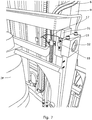
Figs. 6 and7 , the ends of thebridge 18 are secured to apart 31 of themast 6 adjacent itspivot 32 such that thebridge 18 straddles the centre line of thepivot 32. As before, the locations to which the ends of thebridge 18 are secured are, however, static with respect to one another. Thebridge 18 is secured adjacent to thatpart 31 of the mast that is adapted to form a tang of a clevis fastening forming thepivot 32. This enables thestrain gauge 14 to measure load forces tending to stretch themast 6 about thepivot 32. - In use, the present invention enables the
indicator 17 to display to an operator of the invention a more complete picture of the effects caused by loading thevehicle 1 with a given load. Unlike prior art arrangements which only measure the weight and load centre of the load and those which are distorted by torsional and shear forces, the stress to the vehicle directly and solely caused by the tilt angle of themast 6 and the lift height is measured. This is because the locations to which the ends of thebridge 18 of thestrain gauge 14 are secured are static with respect to one another so that the readings taken by thestrain gauge 14 are not distorted by torsional and shear forces. In addition, unlike many conventional arrangements which are secured to the lifting forks or lifting platforms of lifting vehicles, the present invention is chassis based. This greatly reduces the cost of the invention. This is because lifting forks and platforms wear in use and are replaced many times during the life of a vehicle. Load monitors secured to the lifting forks or platforms therefore have to be replaced at the same time, significantly increasing the cost of replacement. However, the present invention does not need to be replaced once fitted when the lifting forks or platform are replaced. Finally, the load monitor and indicator arrangement of the present invention can be readily retrofitted to any existing lifting vehicle. In this regard although the description above describes the invention in relation to a forklift vehicle it will be appreciated that it can be applied to any appropriate lifting vehicle including lifting trolleys and the like. - In some embodiments, the
vehicle 1 may incorporate one or more hydraulic pressure transducers installed in the hydraulic circuitry for the lift andtilt cylinders 8 and 9 and linked to theprocessor 15 in order to provide data to enable theprocessor 15 to calculate the weight ofload 12 carried by thevehicle 1. For example, a hydraulic transducer 33 (seeFig. 2 for a schematic arrangement) may be provided that is used to measure the hydraulic pressure within the hydraulic hose supplying hydraulic pressure to the lift cylinder 8. The readings taken by thetransducer 33 are relayed to theprocessor 15, which uses them to calculate the weight of theload 12. Similarly, afurther transducer 34 may also be provided to measure the hydraulic pressure within the hydraulic hose supplying hydraulic pressure to thetilt cylinder 9 so that the moment M from both load centre position and mast tilt can be taken into account. The weight of theload 12 may then be displayed on theindicator 16. As theprocessor 15 will then be aware when there is noload 12, this can be used to zero the readings from thestrain gauge 14, making the arrangement self-calibrating. Also, as the measured hydraulic pressure is affected by the ambient temperature theprocessor 15 may be programmed to use feedback readings from the strain gauge orstrain gauges 14 to take into account temperature changes in the hydraulic pressure so that the arrangement is aware when a vehicle is driven from one environment to another with a considerably different ambient temperature, for example driving a vehicle from the interior of an building outside, where the temperature may be considerably warmer or colder. - Preferably, the
processor 15 is used to continuously calculate the stability of thevehicle 1 and to weigh theload 12. These data are preferably continuously displayed on theindicator 16 in a format and colour that can be taken in at a glance, for example graphically and in red or green. Anaudible alarm 35, such as a buzzer, is also preferably linked to theprocessor 15 or to theindicator 16 to sound an alarm if an overload or near-tipping condition occurs. Theprocessor 15 may also be adapted to log information and to transfer it, for example by a wireless network to a remote device.
Claims (13)
- A lifting vehicle (1) comprisinga lifting device (7) movably mounted on a mast (6) secured to a chassis (2) of the vehicle (1), raising and lowering of the lifting device (7) on the mast (6) being controlled by a lift cylinder (8) and tilting of the mast (6) forward and backward out of a vertical position being controlled by a tilt cylinder (9) that is mounted by fastenings (24:28) between a part (10) of the chassis (2) and the mast (6);a load monitor (13) comprising a strain gauge (14) mounted on a bridge (18) that is secured at each end to locations that are either on said part (10) of the chassis (2) or on the mast (6) adjacent the fastening (24:28) for the tilt cylinder (9); andan indicator (16) in communication with the load monitor (13) that can signal an output of the load monitor (13) to an operator of the vehicle (1);the locations on said part (10) of the chassis (2) or on the mast (6) to which the ends of the bridge (18) are secured being static with respect to one another.
- A vehicle (1) as claimed in Claim 1, wherein said fastenings (24: 28) are clevis fastenings and the bridge (18) is secured to said part of the chassis (2) or the mast (6) that is adapted to form part of one of said clevis fastenings (24: 28).
- A vehicle (1) as claimed in Claim 2, wherein said part of the chassis (2) or the mast (6) is adapted to form a tang (26; 29) of the clevis fastening (24: 28).
- A vehicle (1) as claimed in any of Claims 1 to 3, wherein the bridge (18) is secured at each end by studs (19) that are stud welded to said part of the chassis (2) or to the mast (6).
- A vehicle (1) as claimed in Claim 4, wherein the studs (19) have been welded to said part of the chassis (2) or the mast (6) by capacitor-discharge stud welding.
- A vehicle (1) as claimed in any of Claims 1 to 5, comprising a pair of tilt cylinders (9) located respectively on each side of the mast (6), each tilt cylinder (9) having a strain gauge (14) associated therewith that is mounted adjacent one of its fastenings and that forms part of said load monitor (13).
- A vehicle (1) as claimed in any of Claims 1 to 6, wherein the or each strain gauge (14) is a resistive strain gauge.
- A vehicle (1) as claimed in Claim 7, wherein the or each resistive strain gauge (14) comprises an insulating flexible backing sheet (21) supporting a metallic foil pattern (22), the backing sheet (21) being adhered to the bridge (18).
- A vehicle (1) as claimed in any of Claims 1 to 8, wherein the or each strain gauge (14) is attached by wiring (17) to a processor (15) which is in communication with the indicator (16) and which processes data from the strain gauge (14) to determine the stability of the vehicle (1).
- A vehicle (1) as claimed in Claim 9, wherein one or more hydraulic pressure transducers (33, 34) are provided that are installed in the hydraulic circuitry for the lift and tilt cylinders (8, 9) and linked to the processor (15) in order to provide data to enable the processor (15) to calculate the weight of a load (12) carried by the vehicle (1).
- A vehicle (1) as claimed in Claim 10, wherein the processor (15) is adapted to use the data from the hydraulic pressure transducer or transducers (33, 34) to zero readings from the strain gauge (14).
- A vehicle (1) as claimed in any of Claims 9 to 11, wherein an audible alarm (35) is provided that is linked to the processor (15) or the indicator (16).
- A vehicle (1) as claimed in any of Claims 9 to 12, wherein the processor (15) is adapted to log information and to transfer it by a wireless network to a remote device.
Applications Claiming Priority (2)
| Application Number | Priority Date | Filing Date | Title |
|---|---|---|---|
| GBGB1506438.9A GB201506438D0 (en) | 2015-04-16 | 2015-04-16 | A lifting vehicle incorporating a load monitor |
| PCT/GB2016/000082 WO2016166500A1 (en) | 2015-04-16 | 2016-04-15 | A lifting vehicle incorporating a load monitor |
Publications (2)
| Publication Number | Publication Date |
|---|---|
| EP3283429A1 EP3283429A1 (en) | 2018-02-21 |
| EP3283429B1 true EP3283429B1 (en) | 2019-10-30 |
Family
ID=53298663
Family Applications (1)
| Application Number | Title | Priority Date | Filing Date |
|---|---|---|---|
| EP16717676.7A Active EP3283429B1 (en) | 2015-04-16 | 2016-04-15 | A lifting vehicle incorporating a load monitor |
Country Status (4)
| Country | Link |
|---|---|
| US (1) | US10322922B2 (en) |
| EP (1) | EP3283429B1 (en) |
| GB (1) | GB201506438D0 (en) |
| WO (1) | WO2016166500A1 (en) |
Families Citing this family (3)
| Publication number | Priority date | Publication date | Assignee | Title |
|---|---|---|---|---|
| JP6365366B2 (en) * | 2015-03-17 | 2018-08-01 | 株式会社豊田自動織機 | Forklift cargo handling equipment |
| RU2711183C1 (en) * | 2019-06-17 | 2020-01-15 | Общество с ограниченной ответственностью "РД Групп" | Strain gauge for measuring load on axis of cargo vehicle and system for measuring load on axis of cargo vehicle |
| CN111121939B (en) * | 2020-01-02 | 2021-03-23 | 深圳市汉德网络科技有限公司 | High-precision vehicle-mounted area weighing method |
Family Cites Families (10)
| Publication number | Priority date | Publication date | Assignee | Title |
|---|---|---|---|---|
| US4003487A (en) * | 1975-04-03 | 1977-01-18 | Allis-Chalmers Corporation | Truck overload protective system having trip signal sampling means |
| US4093091A (en) * | 1976-06-30 | 1978-06-06 | Towmotor Corporation | Load moment sensing system for lift trucks |
| GB1590440A (en) * | 1978-03-23 | 1981-06-03 | Liner Ltd | Load-handling vehicle |
| US4231450A (en) * | 1978-10-23 | 1980-11-04 | White Farm Equipment Company | Overload warning system |
| US4942529A (en) * | 1988-05-26 | 1990-07-17 | The Raymond Corporation | Lift truck control systems |
| JP2000033810A (en) * | 1997-10-09 | 2000-02-02 | Nissan Motor Co Ltd | Rear axle swinging regulation device and regulation method |
| JP2000044196A (en) * | 1998-07-31 | 2000-02-15 | Toyota Autom Loom Works Ltd | Axial force measuring device of tilt cylinder of industrial vehicle |
| US8970363B2 (en) * | 2006-09-14 | 2015-03-03 | Crown Equipment Corporation | Wrist/arm/hand mounted device for remotely controlling a materials handling vehicle |
| US9476418B2 (en) * | 2013-12-17 | 2016-10-25 | General Electric Company | Systems and methods for determining mechanical stress of a compressor |
| US20160187210A1 (en) * | 2014-12-31 | 2016-06-30 | Nate J. Coleman | System and method to measure force or location on an l-beam |
-
2015
- 2015-04-16 GB GBGB1506438.9A patent/GB201506438D0/en not_active Ceased
-
2016
- 2016-04-15 EP EP16717676.7A patent/EP3283429B1/en active Active
- 2016-04-15 US US15/565,744 patent/US10322922B2/en active Active
- 2016-04-15 WO PCT/GB2016/000082 patent/WO2016166500A1/en active Application Filing
Non-Patent Citations (1)
| Title |
|---|
| None * |
Also Published As
| Publication number | Publication date |
|---|---|
| US20180072549A1 (en) | 2018-03-15 |
| US10322922B2 (en) | 2019-06-18 |
| WO2016166500A1 (en) | 2016-10-20 |
| EP3283429A1 (en) | 2018-02-21 |
| GB201506438D0 (en) | 2015-06-03 |
Similar Documents
| Publication | Publication Date | Title |
|---|---|---|
| CN108137300B (en) | Forklift truck | |
| EP2470465B1 (en) | Lifting device and lifting vehicle | |
| US6050770A (en) | Stabilization system for load handling equipment | |
| EP3059202B1 (en) | A lifting vehicle with a transverse stability control system | |
| US4516116A (en) | Apparatus for visually displaying the load-moment, axle-load, or payload of a vehicle | |
| CA1266869A (en) | Vehicle load monitoring system | |
| CA1044713A (en) | Method of indicating a load placed on a load-carrying vehicle platform and corresponding apparatus | |
| US8779306B2 (en) | Weight sensing method and apparatus for forklifts | |
| US20070041820A1 (en) | Fork cover having weighing capability | |
| EP3283429B1 (en) | A lifting vehicle incorporating a load monitor | |
| US20140032060A1 (en) | Method and device for monitoring the stability of a loading crane mounted on a vehicle | |
| KR20190080183A (en) | Axial load sensor module with axle load | |
| KR101863309B1 (en) | Safety Apparatus of a forklift | |
| EP1167638B1 (en) | Device for measurement and control of the conditions of stability of a vehicle, in particular an industrial vehicle | |
| GB2487608A (en) | Clevis pin strain sensor for vehicle payload weighing | |
| US11820372B2 (en) | Tow weight evaluation system for wreckers | |
| CN213112435U (en) | Aerial working platform truck | |
| US20220162048A1 (en) | Carrier for a Lifting Device, Lifting Device Provided Therewith and Method Therefor | |
| JP2010083669A (en) | Allowable load determination device of forklift | |
| CN219259382U (en) | Automatic assessment device for fatigue life of metal structure of bridge crane | |
| US20230384144A1 (en) | Tow weight evaluation system for wreckers | |
| KR102140980B1 (en) | Installation structure of sensor module to measure axial load of vehicle | |
| GB1590440A (en) | Load-handling vehicle | |
| GB2332279A (en) | Arrangement for weighing a load on a vehicle | |
| JPS6176919A (en) | Carrying car having load detecting sensor |
Legal Events
| Date | Code | Title | Description |
|---|---|---|---|
| STAA | Information on the status of an ep patent application or granted ep patent |
Free format text: STATUS: THE INTERNATIONAL PUBLICATION HAS BEEN MADE |
|
| PUAI | Public reference made under article 153(3) epc to a published international application that has entered the european phase |
Free format text: ORIGINAL CODE: 0009012 |
|
| STAA | Information on the status of an ep patent application or granted ep patent |
Free format text: STATUS: REQUEST FOR EXAMINATION WAS MADE |
|
| 17P | Request for examination filed |
Effective date: 20171012 |
|
| AK | Designated contracting states |
Kind code of ref document: A1 Designated state(s): AL AT BE BG CH CY CZ DE DK EE ES FI FR GB GR HR HU IE IS IT LI LT LU LV MC MK MT NL NO PL PT RO RS SE SI SK SM TR |
|
| AX | Request for extension of the european patent |
Extension state: BA ME |
|
| DAV | Request for validation of the european patent (deleted) | ||
| DAX | Request for extension of the european patent (deleted) | ||
| RIC1 | Information provided on ipc code assigned before grant |
Ipc: B66F 9/08 20060101ALI20190301BHEP Ipc: G01G 19/12 20060101ALI20190301BHEP Ipc: G07C 5/08 20060101ALI20190301BHEP Ipc: B66F 17/00 20060101ALI20190301BHEP Ipc: G01L 1/22 20060101ALI20190301BHEP Ipc: B66F 9/07 20060101ALI20190301BHEP Ipc: B66F 9/22 20060101ALI20190301BHEP Ipc: G08B 3/00 20060101ALI20190301BHEP Ipc: B66F 9/075 20060101AFI20190301BHEP |
|
| GRAP | Despatch of communication of intention to grant a patent |
Free format text: ORIGINAL CODE: EPIDOSNIGR1 |
|
| STAA | Information on the status of an ep patent application or granted ep patent |
Free format text: STATUS: GRANT OF PATENT IS INTENDED |
|
| INTG | Intention to grant announced |
Effective date: 20190424 |
|
| GRAS | Grant fee paid |
Free format text: ORIGINAL CODE: EPIDOSNIGR3 |
|
| GRAJ | Information related to disapproval of communication of intention to grant by the applicant or resumption of examination proceedings by the epo deleted |
Free format text: ORIGINAL CODE: EPIDOSDIGR1 |
|
| GRAL | Information related to payment of fee for publishing/printing deleted |
Free format text: ORIGINAL CODE: EPIDOSDIGR3 |
|
| STAA | Information on the status of an ep patent application or granted ep patent |
Free format text: STATUS: REQUEST FOR EXAMINATION WAS MADE |
|
| GRAP | Despatch of communication of intention to grant a patent |
Free format text: ORIGINAL CODE: EPIDOSNIGR1 |
|
| STAA | Information on the status of an ep patent application or granted ep patent |
Free format text: STATUS: GRANT OF PATENT IS INTENDED |
|
| INTC | Intention to grant announced (deleted) | ||
| GRAA | (expected) grant |
Free format text: ORIGINAL CODE: 0009210 |
|
| STAA | Information on the status of an ep patent application or granted ep patent |
Free format text: STATUS: THE PATENT HAS BEEN GRANTED |
|
| INTG | Intention to grant announced |
Effective date: 20190913 |
|
| AK | Designated contracting states |
Kind code of ref document: B1 Designated state(s): AL AT BE BG CH CY CZ DE DK EE ES FI FR GB GR HR HU IE IS IT LI LT LU LV MC MK MT NL NO PL PT RO RS SE SI SK SM TR |
|
| REG | Reference to a national code |
Ref country code: GB Ref legal event code: FG4D |
|
| REG | Reference to a national code |
Ref country code: CH Ref legal event code: EP |
|
| REG | Reference to a national code |
Ref country code: AT Ref legal event code: REF Ref document number: 1195923 Country of ref document: AT Kind code of ref document: T Effective date: 20191115 |
|
| REG | Reference to a national code |
Ref country code: DE Ref legal event code: R096 Ref document number: 602016023300 Country of ref document: DE |
|
| REG | Reference to a national code |
Ref country code: IE Ref legal event code: FG4D |
|
| REG | Reference to a national code |
Ref country code: SE Ref legal event code: TRGR |
|
| REG | Reference to a national code |
Ref country code: NL Ref legal event code: FP |
|
| REG | Reference to a national code |
Ref country code: LT Ref legal event code: MG4D |
|
| PG25 | Lapsed in a contracting state [announced via postgrant information from national office to epo] |
Ref country code: GR Free format text: LAPSE BECAUSE OF FAILURE TO SUBMIT A TRANSLATION OF THE DESCRIPTION OR TO PAY THE FEE WITHIN THE PRESCRIBED TIME-LIMIT Effective date: 20200131 Ref country code: LT Free format text: LAPSE BECAUSE OF FAILURE TO SUBMIT A TRANSLATION OF THE DESCRIPTION OR TO PAY THE FEE WITHIN THE PRESCRIBED TIME-LIMIT Effective date: 20191030 Ref country code: NO Free format text: LAPSE BECAUSE OF FAILURE TO SUBMIT A TRANSLATION OF THE DESCRIPTION OR TO PAY THE FEE WITHIN THE PRESCRIBED TIME-LIMIT Effective date: 20200130 Ref country code: BG Free format text: LAPSE BECAUSE OF FAILURE TO SUBMIT A TRANSLATION OF THE DESCRIPTION OR TO PAY THE FEE WITHIN THE PRESCRIBED TIME-LIMIT Effective date: 20200130 Ref country code: FI Free format text: LAPSE BECAUSE OF FAILURE TO SUBMIT A TRANSLATION OF THE DESCRIPTION OR TO PAY THE FEE WITHIN THE PRESCRIBED TIME-LIMIT Effective date: 20191030 Ref country code: PT Free format text: LAPSE BECAUSE OF FAILURE TO SUBMIT A TRANSLATION OF THE DESCRIPTION OR TO PAY THE FEE WITHIN THE PRESCRIBED TIME-LIMIT Effective date: 20200302 Ref country code: LV Free format text: LAPSE BECAUSE OF FAILURE TO SUBMIT A TRANSLATION OF THE DESCRIPTION OR TO PAY THE FEE WITHIN THE PRESCRIBED TIME-LIMIT Effective date: 20191030 Ref country code: PL Free format text: LAPSE BECAUSE OF FAILURE TO SUBMIT A TRANSLATION OF THE DESCRIPTION OR TO PAY THE FEE WITHIN THE PRESCRIBED TIME-LIMIT Effective date: 20191030 |
|
| PG25 | Lapsed in a contracting state [announced via postgrant information from national office to epo] |
Ref country code: IS Free format text: LAPSE BECAUSE OF FAILURE TO SUBMIT A TRANSLATION OF THE DESCRIPTION OR TO PAY THE FEE WITHIN THE PRESCRIBED TIME-LIMIT Effective date: 20200229 Ref country code: HR Free format text: LAPSE BECAUSE OF FAILURE TO SUBMIT A TRANSLATION OF THE DESCRIPTION OR TO PAY THE FEE WITHIN THE PRESCRIBED TIME-LIMIT Effective date: 20191030 Ref country code: RS Free format text: LAPSE BECAUSE OF FAILURE TO SUBMIT A TRANSLATION OF THE DESCRIPTION OR TO PAY THE FEE WITHIN THE PRESCRIBED TIME-LIMIT Effective date: 20191030 |
|
| PG25 | Lapsed in a contracting state [announced via postgrant information from national office to epo] |
Ref country code: AL Free format text: LAPSE BECAUSE OF FAILURE TO SUBMIT A TRANSLATION OF THE DESCRIPTION OR TO PAY THE FEE WITHIN THE PRESCRIBED TIME-LIMIT Effective date: 20191030 |
|
| PG25 | Lapsed in a contracting state [announced via postgrant information from national office to epo] |
Ref country code: CZ Free format text: LAPSE BECAUSE OF FAILURE TO SUBMIT A TRANSLATION OF THE DESCRIPTION OR TO PAY THE FEE WITHIN THE PRESCRIBED TIME-LIMIT Effective date: 20191030 Ref country code: RO Free format text: LAPSE BECAUSE OF FAILURE TO SUBMIT A TRANSLATION OF THE DESCRIPTION OR TO PAY THE FEE WITHIN THE PRESCRIBED TIME-LIMIT Effective date: 20191030 Ref country code: ES Free format text: LAPSE BECAUSE OF FAILURE TO SUBMIT A TRANSLATION OF THE DESCRIPTION OR TO PAY THE FEE WITHIN THE PRESCRIBED TIME-LIMIT Effective date: 20191030 Ref country code: EE Free format text: LAPSE BECAUSE OF FAILURE TO SUBMIT A TRANSLATION OF THE DESCRIPTION OR TO PAY THE FEE WITHIN THE PRESCRIBED TIME-LIMIT Effective date: 20191030 Ref country code: DK Free format text: LAPSE BECAUSE OF FAILURE TO SUBMIT A TRANSLATION OF THE DESCRIPTION OR TO PAY THE FEE WITHIN THE PRESCRIBED TIME-LIMIT Effective date: 20191030 |
|
| REG | Reference to a national code |
Ref country code: DE Ref legal event code: R097 Ref document number: 602016023300 Country of ref document: DE |
|
| REG | Reference to a national code |
Ref country code: AT Ref legal event code: MK05 Ref document number: 1195923 Country of ref document: AT Kind code of ref document: T Effective date: 20191030 |
|
| PG25 | Lapsed in a contracting state [announced via postgrant information from national office to epo] |
Ref country code: SM Free format text: LAPSE BECAUSE OF FAILURE TO SUBMIT A TRANSLATION OF THE DESCRIPTION OR TO PAY THE FEE WITHIN THE PRESCRIBED TIME-LIMIT Effective date: 20191030 Ref country code: SK Free format text: LAPSE BECAUSE OF FAILURE TO SUBMIT A TRANSLATION OF THE DESCRIPTION OR TO PAY THE FEE WITHIN THE PRESCRIBED TIME-LIMIT Effective date: 20191030 |
|
| PLBE | No opposition filed within time limit |
Free format text: ORIGINAL CODE: 0009261 |
|
| STAA | Information on the status of an ep patent application or granted ep patent |
Free format text: STATUS: NO OPPOSITION FILED WITHIN TIME LIMIT |
|
| 26N | No opposition filed |
Effective date: 20200731 |
|
| PG25 | Lapsed in a contracting state [announced via postgrant information from national office to epo] |
Ref country code: AT Free format text: LAPSE BECAUSE OF FAILURE TO SUBMIT A TRANSLATION OF THE DESCRIPTION OR TO PAY THE FEE WITHIN THE PRESCRIBED TIME-LIMIT Effective date: 20191030 Ref country code: SI Free format text: LAPSE BECAUSE OF FAILURE TO SUBMIT A TRANSLATION OF THE DESCRIPTION OR TO PAY THE FEE WITHIN THE PRESCRIBED TIME-LIMIT Effective date: 20191030 Ref country code: MC Free format text: LAPSE BECAUSE OF FAILURE TO SUBMIT A TRANSLATION OF THE DESCRIPTION OR TO PAY THE FEE WITHIN THE PRESCRIBED TIME-LIMIT Effective date: 20191030 |
|
| REG | Reference to a national code |
Ref country code: CH Ref legal event code: PL |
|
| PG25 | Lapsed in a contracting state [announced via postgrant information from national office to epo] |
Ref country code: LU Free format text: LAPSE BECAUSE OF NON-PAYMENT OF DUE FEES Effective date: 20200415 Ref country code: LI Free format text: LAPSE BECAUSE OF NON-PAYMENT OF DUE FEES Effective date: 20200430 Ref country code: CH Free format text: LAPSE BECAUSE OF NON-PAYMENT OF DUE FEES Effective date: 20200430 |
|
| PGFP | Annual fee paid to national office [announced via postgrant information from national office to epo] |
Ref country code: IT Payment date: 20210423 Year of fee payment: 6 Ref country code: FR Payment date: 20210427 Year of fee payment: 6 |
|
| PGFP | Annual fee paid to national office [announced via postgrant information from national office to epo] |
Ref country code: BE Payment date: 20210426 Year of fee payment: 6 Ref country code: SE Payment date: 20210422 Year of fee payment: 6 |
|
| PG25 | Lapsed in a contracting state [announced via postgrant information from national office to epo] |
Ref country code: TR Free format text: LAPSE BECAUSE OF FAILURE TO SUBMIT A TRANSLATION OF THE DESCRIPTION OR TO PAY THE FEE WITHIN THE PRESCRIBED TIME-LIMIT Effective date: 20191030 Ref country code: MT Free format text: LAPSE BECAUSE OF FAILURE TO SUBMIT A TRANSLATION OF THE DESCRIPTION OR TO PAY THE FEE WITHIN THE PRESCRIBED TIME-LIMIT Effective date: 20191030 Ref country code: CY Free format text: LAPSE BECAUSE OF FAILURE TO SUBMIT A TRANSLATION OF THE DESCRIPTION OR TO PAY THE FEE WITHIN THE PRESCRIBED TIME-LIMIT Effective date: 20191030 |
|
| PG25 | Lapsed in a contracting state [announced via postgrant information from national office to epo] |
Ref country code: MK Free format text: LAPSE BECAUSE OF FAILURE TO SUBMIT A TRANSLATION OF THE DESCRIPTION OR TO PAY THE FEE WITHIN THE PRESCRIBED TIME-LIMIT Effective date: 20191030 |
|
| REG | Reference to a national code |
Ref country code: SE Ref legal event code: EUG |
|
| REG | Reference to a national code |
Ref country code: BE Ref legal event code: MM Effective date: 20220430 |
|
| PG25 | Lapsed in a contracting state [announced via postgrant information from national office to epo] |
Ref country code: SE Free format text: LAPSE BECAUSE OF NON-PAYMENT OF DUE FEES Effective date: 20220416 Ref country code: FR Free format text: LAPSE BECAUSE OF NON-PAYMENT OF DUE FEES Effective date: 20220430 |
|
| PG25 | Lapsed in a contracting state [announced via postgrant information from national office to epo] |
Ref country code: BE Free format text: LAPSE BECAUSE OF NON-PAYMENT OF DUE FEES Effective date: 20220430 |
|
| PGFP | Annual fee paid to national office [announced via postgrant information from national office to epo] |
Ref country code: IE Payment date: 20230222 Year of fee payment: 8 |
|
| PG25 | Lapsed in a contracting state [announced via postgrant information from national office to epo] |
Ref country code: IT Free format text: LAPSE BECAUSE OF NON-PAYMENT OF DUE FEES Effective date: 20220415 |
|
| PGFP | Annual fee paid to national office [announced via postgrant information from national office to epo] |
Ref country code: GB Payment date: 20230222 Year of fee payment: 8 |
|
| PGFP | Annual fee paid to national office [announced via postgrant information from national office to epo] |
Ref country code: NL Payment date: 20230424 Year of fee payment: 8 |
|
| PGFP | Annual fee paid to national office [announced via postgrant information from national office to epo] |
Ref country code: DE Payment date: 20230427 Year of fee payment: 8 |