EP3282374A1 - User interface data sample transformer - Google Patents
User interface data sample transformer Download PDFInfo
- Publication number
- EP3282374A1 EP3282374A1 EP17185392.2A EP17185392A EP3282374A1 EP 3282374 A1 EP3282374 A1 EP 3282374A1 EP 17185392 A EP17185392 A EP 17185392A EP 3282374 A1 EP3282374 A1 EP 3282374A1
- Authority
- EP
- European Patent Office
- Prior art keywords
- dataset
- database
- data
- transformation
- receiving
- Prior art date
- Legal status (The legal status is an assumption and is not a legal conclusion. Google has not performed a legal analysis and makes no representation as to the accuracy of the status listed.)
- Ceased
Links
Images


Classifications
-
- G—PHYSICS
- G06—COMPUTING; CALCULATING OR COUNTING
- G06F—ELECTRIC DIGITAL DATA PROCESSING
- G06F16/00—Information retrieval; Database structures therefor; File system structures therefor
- G06F16/20—Information retrieval; Database structures therefor; File system structures therefor of structured data, e.g. relational data
- G06F16/25—Integrating or interfacing systems involving database management systems
- G06F16/254—Extract, transform and load [ETL] procedures, e.g. ETL data flows in data warehouses
-
- G—PHYSICS
- G06—COMPUTING; CALCULATING OR COUNTING
- G06F—ELECTRIC DIGITAL DATA PROCESSING
- G06F16/00—Information retrieval; Database structures therefor; File system structures therefor
- G06F16/20—Information retrieval; Database structures therefor; File system structures therefor of structured data, e.g. relational data
- G06F16/25—Integrating or interfacing systems involving database management systems
- G06F16/252—Integrating or interfacing systems involving database management systems between a Database Management System and a front-end application
-
- G—PHYSICS
- G06—COMPUTING; CALCULATING OR COUNTING
- G06F—ELECTRIC DIGITAL DATA PROCESSING
- G06F21/00—Security arrangements for protecting computers, components thereof, programs or data against unauthorised activity
- G06F21/50—Monitoring users, programs or devices to maintain the integrity of platforms, e.g. of processors, firmware or operating systems
- G06F21/55—Detecting local intrusion or implementing counter-measures
- G06F21/56—Computer malware detection or handling, e.g. anti-virus arrangements
- G06F21/562—Static detection
- G06F21/565—Static detection by checking file integrity
-
- G—PHYSICS
- G06—COMPUTING; CALCULATING OR COUNTING
- G06F—ELECTRIC DIGITAL DATA PROCESSING
- G06F3/00—Input arrangements for transferring data to be processed into a form capable of being handled by the computer; Output arrangements for transferring data from processing unit to output unit, e.g. interface arrangements
- G06F3/01—Input arrangements or combined input and output arrangements for interaction between user and computer
- G06F3/048—Interaction techniques based on graphical user interfaces [GUI]
Definitions
- the present disclosure generally relates to the technical field of special-purpose machines that facilitate data manipulation and validation including computerized variants of such special-purpose machines and improvements to such variants, and to the technologies by which such special-purpose machines become improved compared to other special-purpose machines that facilitate data manipulation and validation.
- the present disclosure addresses systems and methods for user interface data sample based transformations of data.
- raw data can be imported and transformed using a sample portion of the raw data.
- the raw data may be unstructured or structured data.
- the transformations may define structure for the raw data, change pre-existing structure (e.g., schema) of the data, add or remove portions of the data, modify the data values, or modify data types assigned to data values in the raw data.
- a sample portion of the raw data is displayed in a UI with a control menu.
- the control menu includes one or more transformation elements (e.g., buttons, drop-downs, fields) that are configured to apply transformations to the raw data.
- the transformations are applied to the sample portions of the data in real time or near real time, without applying the transformations to the raw data not in the sample. In this way, by applying each transformation only to the sample displayed in the UI, the user can see the changes applied to the sample and judge whether the transformations were applied properly and further determine whether additional transformations are need to further transform the raw data into structured data.
- the transformations are recorded as a transformation job that can be applied to the rest of the raw data (e.g., the raw data not included in the displayed sample set) stored in a backend database.
- the transformations on the rest of the raw data transform the raw data into a structured form per the transformation job recorded from the sample dataset transformations.
- the transformation job is automatically applied to the new raw data, and stored with the structured data in the database backend.
- the newer raw data may comprise entirely new values in raw format or updates to the data already transformed and stored in a backend database.
- the transformations specify types of validations to occur when transforming the data (e.g., exclude data outside a defined range of values, make sure a given column contains only integers). If, during the transformations, an error occurs due to one or more validations failing, an error message is generated; the user can ignore the error message, correct the error manually, or create a new transformation task to address future errors of the same type.
- a user can effectuate transformations to arbitrarily large datasets (e.g., trillions of rows, thousands of columns) through a fast and responsive UI-based approach that shows the results of the transformations in real time and uses a transformation job to transform raw data into a structured form ready for analysis.
- arbitrarily large datasets e.g., trillions of rows, thousands of columns
- a network-based data analysis system 104 provides server-side functionality via a network 102 (e.g., the Internet or wide area network (WAN)) to one or more client devices 106 and 108.
- a data architect user e.g., user 196
- an analyst user e.g., user 198
- the data visualizer application 128 is an application to import, transform, and visualize data.
- user 196 can use the data visualizer application 128 to import raw data and transform it for storage and later analysis. Further, user 198 can use the data visualizer application 128 to view the data transformed per user 196.
- the data visualizer application 128 is run as local software executed by processors of the client device (e.g., client device 106 and client device 108).
- the data visualizer application 128 is run from a web client (e.g., a browser) as a cloud service that works with application server 118 to provide cloud services (e.g., cloud-based data analysis).
- the client devices 106 and 108 each comprise a computing device that includes at least a display and communication capabilities that provide access to the network-based data analysis system 104 via the network 102.
- the client device can be implemented as, but is not limited to, a remote device, work station, Internet appliance, hand-held device, wireless device, portable device, wearable computer, cellular or mobile phone, Personal Digital Assistant (PDA), smart phone, tablet, ultrabook, netbook, laptop, desktop, multiprocessor system, microprocessor-based or programmable consumer electronic, game consoles, set-top box, network Personal Computer (PC), mini-computer, and so forth.
- PDA Personal Digital Assistant
- the data visualizer application 128 accesses the various systems of the network-based data analysis system 104 via the web interface supported by a web server 122. Similarly, in some embodiments, the data visualizer application 128 can initiate tasks to be performed programmatically (e.g., automatically) without user input. In those example embodiments, the data visualizer application 128 can interface to perform the programmatic tasks through an Application Program Interface (API) server 114 located on the server side (e.g., within network-based data analysis system 104).
- API Application Program Interface
- Users comprise a person, a machine, or other means of interacting with the client devices (e.g., client device 106 and 108).
- the user is not part of the network architecture 100, but interacts with the network architecture 100 via the client devices 106 and 108.
- the user 196 provides input (e.g., touch screen input or alphanumeric input) to the client device 106 and the input is communicated to the network-based data analysis system 104 via the network 102.
- the network-based data analysis system 104 in response to receiving the input from the user 196, communicates information from application server 118 to the client device 106 via the network 102 to be presented to the user 196.
- users can interact with the network-based data analysis system 104 using their respective client devices.
- the API server 114 and the web server 122 are coupled to, and provide programmatic and web interfaces respectively to, one or more application server 118.
- the application server 118 can host a UI sample transformer 124 configured to receive raw data, and perform transformations on a sample of the raw data to record as a transformation job.
- the UI sample transformer 124 may create a sample of the raw data for display on data visualizer application 128 for transformation job generation.
- the portion of the raw data not included in the sample is stored in a database system (e.g., database backend), such as database system 120.
- the raw data not in the sample can be distributed across data stores 122A-N, which are configured to work as distributed data stores for a distributed database system.
- the database system 120 is implemented as an Apache Hadoop-based system, which may implement Hadoop techniques (e.g., MapReduce) on Hadoop Distributed File System (HDFS) datastores, such as data stores122A-N.
- Hadoop and HDFS are mere examples of the database system 120 and features and file implementations may be modified.
- the data stores122A-N are HDFS formatted files which can be transformed using Apache Spark functionality that is integrated into UI sample transformer 124.
- FIG. 2 illustrates a block diagram showing components provided within the UI sample transformer 124, according to some example embodiments.
- each functional component e.g., engine, module, or database
- FIG. 2 may be implemented using hardware (e.g., a processor of a machine) or a combination of logic (e.g., executable software instructions) and hardware (e.g., memory and processor of a machine) for executing the logic.
- the various functional components depicted in FIG. 2 may reside on a single machine (e.g., a server) or may be distributed across several machines in various arrangements such as cloud-based architectures.
- any two or more of these components may be combined into a single component (e.g., a single module), and the functions described herein for a single component may be subdivided among multiple modules.
- the UI sample transformer 124 comprises multiple engines that implement data transformation of raw data into structured data, according to some example embodiments.
- the components themselves are communicatively coupled (e.g., via appropriate interfaces) to each other and to various data sources, so as to allow information to be passed between the applications or so as to allow the applications to share and access common data.
- components such as the transformation engine 205
- one or more components of the UI sample transformer 124 may be integrated into a client-side program (e.g., data visualizer application 128) to improve responsiveness.
- the UI sample transformer 124 comprises an interface engine 200, a transformation engine 205, a record engine 210, a database engine 215, an analysis engine 220, and a validation engine 225.
- the interface engine 200 manages generating and displaying user interfaces on the client devices 106 and 108 using the data visualizer application 128.
- the interface engine 200 generates a UI display of a sample dataset of data to be imported and control elements that can be manipulated by the user to effectuate changes to the displayed sample dataset.
- the transformation logic is provided by transformation engine 205, which is configured to receive specific transformation commands from the UI, apply the transformation commands to the sample dataset, and pass the resultant transformed data to the interface engine 200, which then transmits the resultant transformed data to the client device for display by the data visualizer application 128. How the transformations are applied and example types of transformations are discussed in further detail below, with reference to FIGS. 6A-E .
- the transformation engine 205 is located in the data visualizer application 128 and transformations are implemented by the client-side transformation engine 205 using a client side programming language (e.g., browser-executable code type, browser executed JavaScript, code executed locally by client device 106), which allow the user to quickly see the changes he/she is making to the sample dataset in real time or near real time, without waiting for the transformations to be applied to the full raw dataset, which may be many petabytes in size.
- client side programming language e.g., browser-executable code type, browser executed JavaScript, code executed locally by client device 106
- the record engine 210 is configured to record the applied transformations (e.g., types of transformations applied, and order of transformations applied) to the sample dataset. As with the transformation engine 205, in some embodiments, the record engine 210 is integrated into the data visualizer application 128 to record client-side transformations applied to the sample dataset. Upon a build command being selected, the record engine 210 uses the selected transformations to generate a transformation job, which is then transmitted to the UI sample transformer 124. The UI sample transformer 124 then applies the transformation job to the rest of the raw data stored in the database system 120.
- the applied transformations e.g., types of transformations applied, and order of transformations applied
- the record engine 210 is integrated into the data visualizer application 128 to record client-side transformations applied to the sample dataset.
- the record engine 210 uses the selected transformations to generate a transformation job, which is then transmitted to the UI sample transformer 124.
- the UI sample transformer 124 then applies the transformation job to the rest of the raw data stored in the database
- the record engine 210 is configured to generate the transformation job into a database-executable code type that executes across a distributed data storage system.
- the browser-executable code type cannot be natively run on the database as it is configured as client-side script (e.g., JavaScript) that can be used to quickly apply transformations to the sample dataset.
- client-side script e.g., JavaScript
- the database-executable code type cannot be natively run on the browser because the database-executable code type is code configured for functional programming (e.g., MapReduce) on a database backend, not a client side browser.
- a transformation to the sample dataset involves locating a delimiter value and deleting values that appear before the delimiter value (e.g., if the data is "firstName;lastName", the transformation would identify the delimiter ";” and delete the value before the delimiter, which is the "firstName” value).
- the transformation engine 205 may apply the process to the sample dataset directly, locating the specified delimiter and removing values that appear before the delimiter, and display the results directly in the display of the client device.
- the record engine 210 records the transformation as a task that may be applied in each node that manages each datastore (e.g., datastore 122A, datastore 122B).
- the record engine 210 may record the task as part of a mapper code in a MapReduce sequence that can be applied across all the data stores concurrently (e.g., in parallel).
- the record engine 210 records the task as part of an Apache Spark job to be performed by Spark workers across all data stores concurrently (e.g., in parallel).
- the database engine 215 is configured to receive the transformation job from the record engine 210 and apply the transformations to the raw data in the data stores122A-N in database system 120.
- the database engine 215 may be implemented using different types of database systems (e.g., Apache Hadoop and HDFS, Oracle RDMS) and the record engine 210 transforms the code applied to the sample dataset (which is configured to only apply the transformation to the small displayed sample dataset) into code that can be applied at very large scales by the database engine 215.
- the validation engine 225 manages validation logic for the transformations applied to the raw data. As new raw data is received, the validation engine 225 retrieves the transformation job that was created by the record engine 210 and instructs the database engine 215 to apply the transformation job to the new raw data to transform the new raw data into new structured data, to be added to the originally transformed data stored in the data stores 122A-N. The process of transforming new raw data into new structured data can be performed automatically by the UI sample transformer 124 (e.g., via validation engine 225) without requiring the user to redo the transformations on the sample dataset to create the transformation job. If an error is encountered while transforming the new raw data, the validation engine 225 generates an error for the user to address. To address the error, the user may correct the faulty values in the new raw data, the user can choose to ignore the error, or the user can create a new transformation task to be included as part of the transformation job so that future errors are avoided.
- an architect user e.g., user 196
- Other users such as user 198, can analyze the structured data using the data visualizer application 128. Because the potentially large set of transformed data is handled on the backend (e.g., across data stores 122A-122N), the analyst user 198 can quickly apply filters to the data to hone the data down to understandable results.
- the analysis engine 220 is configured to generate filtered commands that the database engine 215 can use to retrieve filtered data from data stores 122A-N. Further, because new data is automatically transformed using the pre-configured transformation job, the analyst user 198 can simply use a refresh command to check whether new data has been added to the data stores 122A-N, instead of rerunning a transformation job on the entire dataset.
- FIG. 3 illustrates a flow diagram for a method 300 of transforming large sets of data using the UI sample dataset-based approached, according to some example embodiments.
- the UI sample transformer 124 receives raw data (e.g., an input dataset) to be transformed.
- the raw data is in non-validated form in that further changes are required to make the data valid or parsable by the data visualizer application 128.
- the raw data may be in unstructured form (e.g., lists without delimiters, images).
- the raw data may have some structure, such as columns, but the user still desires to transform the data to a desired structure so that that the data can be parsed and analyzed.
- the database engine 215 stores the raw data in the database system 120 and partitions off a sample of the raw data to be displayed by the interface engine 200.
- the transformation engine 205 receives one or more transformations from the user (e.g., user 196). In response, the transformation engine 205 applies the received transformations to the sample dataset, and displays the result on the data visualizer application 128.
- the UI sample transformer 124 receives the build command from the user through the user interface.
- the record engine 210 in response to receiving the build command, generates a transformation job that includes the one or more transformations received at operation 310.
- the record engine 210 records the transformations by translating the transformations from commands to be applied to the sample dataset (e.g., command to be run on a single table) into commands that run on at a large scale on database system 120, e.g., distributed database commands.
- the database engine 215 applies the transformation job to the raw dataset to transform the raw dataset into a structured format. For instance, the transformation job applies each of the transformations performed on the sample dataset to the raw dataset, thereby transforming the raw dataset into a structured dataset.
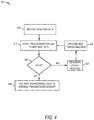
- FIG. 4 shows a flow diagram for a method 400 of transforming new raw data and validations, according to some example embodiments.
- Validations are performed to ensure newer data is transformed by the transformation job properly (e.g., so that the newly received data can be added to the already transformed structured data in data stores 122A-N).
- An example validation includes checking that certain types of data are in certain forms (e.g., check that a given column contains only string characters).
- a further example of a validation is checking whether values are within a given range (e.g., checking that the values in a given column are between a minimum and maximum value, checking that the values of a given column are within some standard deviation value of the total values in the column).
- the UI sample transformer 124 receives new raw data to be transformed.
- the database engine 215 automatically transfers (e.g., upon receipt by the UI sample transformer 124) the new data to the database system 120 for storage in data stores122A-N. Because the raw data is not yet structured, the newer raw data is stored in a staging partition in the data stores122A-N.
- the new raw data is in the same or similar form as the original raw data for which the transformation job was created.
- the new raw data is assumed to be in the same form because the data was uploaded from the same source (e.g., user uploads more data to the transformation job project).
- the user 196 determines that the newer data is in the same or similar form as the original raw data and, accordingly, the user 196 chooses the same transformation job (e.g., the transformation job created to transform the original raw data) for application to the newer data.
- the UI sample transformer 124 creates a project session for each transformation job, and if a user (e.g., user 196) uploads the data to the project session, the UI sample transformer 124 automatically applies the transformation job for that project session.
- a user e.g., user 196
- the user manually uploads the new raw data, and then manually selects the transformation job to be applied to the new raw data.
- the user may visually ascertain that the new raw data is in the same unstructured format as the original raw data (e.g., the raw data received in operation 305, in FIG. 3 ) and accordingly select the same transformation job (e.g., the transformation job created at operation 320, of FIG. 3 ).
- the database engine 215 applies the transformation job to the new raw data stored in the staging partition of the data stores122A-N.
- the database engine 215 encounters an error when applying the transformation job to the new raw data, the error is passed to the validation engine 225 for operation 425. For example, if a transformation to be applied is configured to identify a semi-colon as a delimiter, and a given value does not have a delimiter, the database engine 215 determines that validation has failed at operation 420 because there is an error in the data (e.g., missing delimiter).
- the validation engine 225 receives the error (e.g., error data received from database engine 215) and generates an error message for the user (e.g., user 196) to manage the error.
- the validation error is due to failure of a transformation task. For example, if a transformation task specifies that a given column is to have its values transformed from an integer data type to floating point data type, and the column contains strings, then the transformation task may fail as the database engine 215 may not be configured to transform strings to floating point data types.
- the database engine 215 ignores the error and the values that caused the error are left in uncorrected form in the newer transformed dataset.
- the user corrects the values that caused the error (e.g., by deleting a stray delimiter in the new raw data that caused an error).
- the transformation engine 205 receives from the user (e.g., user 196) a new transformation task to be included in the transformation job to address the error, as illustrated at operation 430. Once the error is handled (e.g., by correcting the error or creating a new transformation) the transformation job is again reapplied to the newer raw data at operation 410.
- the new raw data is thereby transformed into new structured data, and is added to the partition that stores the originally transformed raw data in data stores 122A-N.
- the data visualizer application 128 allows users (e.g., user 198) to quickly retrieve, filter, and analyze the information. Furthermore, in contrast to past approaches, because new raw data is automatically transformed using the transformation job, the analyst user (e.g., user 198) does not have to run a full transformation job his/herself to analyze the latest data.
- FIG. 5 shows a flow diagram for a method 500 of analyzing structured data transformed using the approaches disclosed herein, according to some example embodiments.
- the analysis engine 220 receives an analysis request from an analyst user (e.g., user 198).
- the analysis request may be a request to filter out portions of the structured data (e.g., return data only matching certain ranges) and/or visualize the structured data using a data visualization graph (e.g., social network graph, histogram).
- a data visualization graph e.g., social network graph, histogram
- the database engine 215 receives the analysis request and applies operations of the analysis request to the structured data. For example, if the analysis request of operation 505 requests only rows having a value between a minimum and maximum, the database engine 215 formulates a query configured to run on database system 120 and retrieves the matching rows from the structured data. The database engine 215 then transmits the matching rows to the analysis engine 220 for further visualization or other operations specified in the analysis request. At operation 515, the analysis engine 220 displays the requested analysis results to the user through a display of the data visualizer application 128.
- the new raw data and all of operations of FIG. 4 occurred between operations 515 and 520 of FIG. 5 . That is, assume that after viewing the requested analysis data, newer data is received and transformed using the transformation job, and further that the transformed data is stored in the distributed database system 120. Continuing, further assume that at operation 520, the user (e.g., user 198) wants to refresh the data to get the latest data for analysis. Conventionally, the user would have to run the transformation job on the newly received data, or wait for other users with expertise to transform the data. However, using the approach here, the transformation job was quickly created using the sample-based approach.
- users of the data visualizer application 128 can transform and analyze data in an efficient, accurate way.
- the analysis engine 220 receives an update request from the analyst user (e.g., user 198).
- the update request is a type a refresh requests configured to check whether any new data has been added to the data being analyzed (e.g., the transformed data stored in data stores 122A-N).
- the database engine 215 retrieves data matching the operations of the analysis request.
- the analysis engine 220 display the requested data using one or more graphical data visualizations (e.g., network graph, point plot, histogram).
- FIGS. 6A-E depict example user interfaces for the UI sample transformer 124, according to some embodiments.
- alternate presentations of the displays of FIGS. 6A-E can include additional information, graphics, options, and so forth. Alternatively, other presentations can include less information, or provide abridged information for easy use by the user.
- FIG. 6A shows a graphical user interface 600 for transforming data according to some example embodiments.
- the user interface 600 includes a control menu 602 with display objects 604a-e (e.g., buttons, drop-downs, fields) that are selectable by a user (e.g., user 196, user 198) for uploading raw data, applying transformations, selecting filters and graphical visualizations, and other operations discussed herein.
- display object 604a can be configured as a data upload tool that allows a user (e.g., user 196) to select raw data for upload to the application server 118 and UI sample transformer 124.
- a sample dataset 606 of the raw data that represents the unstructured form of the data to be uploaded (e.g., the sample data is subset of the raw data that is stratified to accurately represent the raw dataset) is displayed within a portion of user interface 600.
- the user e.g., user 196
- transformation display objects 604b and 604c can be used to perform different transformations on the sample dataset 606.
- FIG. 6A-E it is appreciated that in some example embodiments, more transformation display objects can be included in control menu 602, in different menus and areas within user interface 600, or as pop-up menus that appear upon selecting or visually manipulating data values within sample dataset 606.
- Display object(s) 604d can be options for graphical visualizations to be applied to the sample dataset 606 and/or the transformed full dataset.
- the transformations selected by the user are displayed in the transformation area 616.
- a user e.g., user 196
- he/she may select the build display object 610e, which triggers the record engine 210 to generate a transformation job from each of the applied transformations.
- FIG. 6B shows the result of a first sample transformation on the sample dataset 606 through the user interface 600, according to some example embodiments.
- the user e.g., user 196
- each row in the top row of the sample dataset 606 is a header for the column of values below each top row value (e.g., the "name" value is a header for a column of name values for each of the rows or entries below the top row).
- transformation engine 205 identifies the sample dataset 606 as a table with columns having values set by the top row values.
- the first transformation is shown as a first transformation task in the transformation area 616.
- FIG. 6C shows the result of a second sample transformation on the sample dataset 606 through the user interface 600, according to some example embodiments.
- the user e.g., user 196
- the user combined two columns, the height column ("HT") and the weight column ("WT)" into a single column, with the below values to be separated by a semi-colon delimiter (";"). Consequently, as illustrated, the two columns are combined into a single column with the corresponding column values per row separated by the semi-colon delimiter.
- the second transformation is shown as a second transformation task in the transformation area 616.
- FIG. 6D shows the result of a third sample transformation on the sample dataset 606 through the user interface 600, according to some example embodiments.
- the user e.g., user 196
- the second row which contained data for the person "H. Lorentz”
- the third transformation is shown as a third transformation task in the transformation area 616.
- FIG. 6E shows the result of a fourth sample transformation on the sample dataset 606 through the user interface 600, according to some example embodiments.
- the user e.g., user 196
- the fourth transformation is shown as a fourth transformation task (e.g., validation transformation) in the transformation area 616.
- the user 196 selects the build display object 610e.
- the record engine 210 identifies each of the transformations tasks (e.g., validation transformations) applied to the sample dataset 606 and generates a transformation job in code that is configured to run on the backend, at scale (e.g., runnable in parallel across data stores 122A-N).
- the record engine 210 then passes the transformation job code to the database engine 215, which applies the transformation job to raw data in the database system 120 to transform the raw data to structured data that matches the changes made to the sample dataset 606.
- FIG. 7 shows a network interaction diagram 700 showing network interactions for UI sample dataset-based transformations to large sets of data, according to some embodiments.
- the computing entities include the client device 106, which runs the data visualizer application 128, which communicates over network 102 (represented by a vertical dashed line) to the application server 118, which hosts the UI sample transformer 124, and which further issues instructions to the database system 124 over a network (represented by an additional vertical dashed line).
- the user 196 uploads the raw dataset to the application server 118.
- the UI sample transformer 124 e.g., the database engine 215 stores the uploaded raw data to the network-based data analysis system 104.
- the network-based data analysis system 104 receives the raw dataset from the UI sample transformer 124 and stores it in a database, e.g., in distributed form across data stores 122A-N.
- the database engine 215 generates a sample dataset of the uploaded raw data for UI-based transformations.
- the sample dataset should be small enough to maintain responsiveness in a UI on client device 106.
- the sample dataset may comprise all of the columns (e.g., schema) for a given dataset but only a small number of rows (e.g., less than 100). In this way, the transformations applied to the sample dataset will yield the same results when applied to the large raw dataset because the sample dataset accurately reflects the schema structure of the raw dataset, but only over a few rows.
- the client device 106 displays the sample dataset, as illustrated in FIG. 6A .
- the user 196 applies one or more transformations to the dataset, as illustrated in FIGS. 6B-E .
- the record engine 210 in response to the user 196 selecting the build display object 610e, the record engine 210 generates a transformation job configured to run on the network-based data analysis system 104.
- the database engine 215 receives the transformation job code and applies the transformation job to the raw data in the network-based data analysis system 104.
- the network-based data analysis system 104 receives instructions from the database system 120 and applies the transformations on the raw data across the data stores122A-N in parallel.
- Modules can constitute either software modules (e.g., code embodied on a machine-readable medium) or hardware modules.
- a "hardware module” is a tangible unit capable of performing certain operations and can be configured or arranged in a certain physical manner.
- one or more computer systems e.g., a standalone computer system, a client computer system, or a server computer system
- one or more hardware modules of a computer system e.g., a processor or a group of processors
- software e.g., an application or application portion
- a hardware module can be implemented mechanically, electronically, or any suitable combination thereof.
- a hardware module can include dedicated circuitry or logic that is permanently configured to perform certain operations.
- a hardware module can be a special-purpose processor, such as a Field-Programmable Gate Array (FPGA) or an Application Specific Integrated Circuit (ASIC).
- a hardware module may also include programmable logic or circuitry that is temporarily configured by software to perform certain operations.
- a hardware module can include software executed by a general-purpose processor or other programmable processor. Once configured by such software, hardware modules become specific machines (or specific components of a machine) uniquely tailored to perform the configured functions and are no longer general-purpose processors. It will be appreciated that the decision to implement a hardware module mechanically, in dedicated and permanently configured circuitry, or in temporarily configured circuitry (e.g., configured by software) can be driven by cost and time considerations.
- hardware module should be understood to encompass a tangible entity, be that an entity that is physically constructed, permanently configured (e.g., hardwired), or temporarily configured (e.g., programmed) to operate in a certain manner or to perform certain operations described herein.
- “hardware-implemented module” refers to a hardware module. Considering embodiments in which hardware modules are temporarily configured (e.g., programmed), each of the hardware modules need not be configured or instantiated at any one instance in time. For example, where a hardware module comprises a general-purpose processor configured by software to become a special-purpose processor, the general-purpose processor may be configured as respectively different special-purpose processors (e.g., comprising different hardware modules) at different times. Software accordingly configures a particular processor or processors, for example, to constitute a particular hardware module at one instance of time and to constitute a different hardware module at a different instance of time.
- Hardware modules can provide information to, and receive information from, other hardware modules. Accordingly, the described hardware modules can be regarded as being communicatively coupled. Where multiple hardware modules exist contemporaneously, communications can be achieved through signal transmission (e.g., over appropriate circuits and buses) between or among two or more of the hardware modules. In embodiments in which multiple hardware modules are configured or instantiated at different times, communications between such hardware modules may be achieved, for example, through the storage and retrieval of information in memory structures to which the multiple hardware modules have access. For example, one hardware module can perform an operation and store the output of that operation in a memory device to which it is communicatively coupled. A further hardware module can then, at a later time, access the memory device to retrieve and process the stored output. Hardware modules can also initiate communications with input or output devices, and can operate on a resource (e.g., a collection of information).
- a resource e.g., a collection of information
- processors that are temporarily configured (e.g., by software) or permanently configured to perform the relevant operations. Whether temporarily or permanently configured, such processors constitute processor-implemented modules that operate to perform one or more operations or functions described herein.
- processor-implemented module refers to a hardware module implemented using one or more processors.
- the methods described herein can be at least partially processor-implemented, with a particular processor or processors being an example of hardware.
- a particular processor or processors being an example of hardware.
- the operations of a method can be performed by one or more processors or processor-implemented modules.
- the one or more processors may also operate to support performance of the relevant operations in a "cloud computing" environment or as a "software as a service” (SaaS).
- SaaS software as a service
- at least some of the operations may be performed by a group of computers (as examples of machines including processors), with these operations being accessible via a network (e.g., the Internet) and via one or more appropriate interfaces (e.g., an Application Program Interface (API)).
- API Application Program Interface
- the performance of certain of the operations may be distributed among the processors, not only residing within a single machine, but deployed across a number of machines.
- the processors or processor-implemented modules can be located in a single geographic location (e.g., within a home environment, an office environment, or a server farm). In other example embodiments, the processors or processor-implemented modules are distributed across a number of geographic locations.
- the modules, methods, applications and so forth described in conjunction with FIGS. 1-7 are implemented in some embodiments in the context of a machine and an associated software architecture. The sections below describe representative software architecture and machine (e.g., hardware) architecture that are suitable for use with the disclosed embodiments.
- FIG. 8 is a block diagram illustrating components of a machine 800, according to some example embodiments, able to read instructions from a machine-readable medium (e.g., a machine-readable storage medium) and perform any one or more of the methodologies discussed herein.
- FIG. 8 shows a diagrammatic representation of the machine 800 in the example form of a computer system, within which instructions 816 (e.g., software, a program, an application, an applet, an app, or other executable code) for causing the machine 800 to perform any one or more of the methodologies discussed herein can be executed.
- the instructions 816 can cause the machine 800 to execute the flow diagrams of FIGS. 3-5 and network interaction diagram of FIG. 7 .
- the instructions 816 can implement the interface engine 200, transformation engine 205, record engine 210, database engine 215, analysis engine 220, and validation engine 225 of FIG. 2 , and so forth.
- the instructions 816 transform the general, non-programmed machine into a particular machine 800 programmed to carry out the described and illustrated functions in the manner described.
- the machine 800 operates as a standalone device or can be coupled (e.g., networked) to other machines.
- the machine 800 may operate in the capacity of a server machine or a client machine in a server-client network environment, or as a peer machine in a peer-to-peer (or distributed) network environment.
- the machine 800 can comprise, but not be limited to, a server computer, a client computer, a personal computer (PC), a tablet computer, a laptop computer, a netbook, a set-top box (STB), a personal digital assistant (PDA), an entertainment media system, a cellular telephone, a smart phone, a mobile device, a wearable device (e.g., a smart watch), a smart home device (e.g., a smart appliance), other smart devices, a web appliance, a network router, a network switch, a network bridge, or any machine capable of executing the instructions 816, sequentially or otherwise, that specify actions to be taken by the machine 800.
- the term "machine” shall also be taken to include a collection of machines 800 that individually or jointly execute the instructions 816 to perform any one or more of the methodologies discussed herein.
- the machine 800 can include processors 810, memory/storage 830, and I/O components 850, which can be configured to communicate with each other such as via a bus 802.
- the processors 810 e.g., a Central Processing Unit (CPU), a Reduced Instruction Set Computing (RISC) processor, a Complex Instruction Set Computing (CISC) processor, a Graphics Processing Unit (GPU), a Digital Signal Processor (DSP), an Application Specific Integrated Circuit (ASIC), a Radio-Frequency Integrated Circuit (RFIC), another processor, or any suitable combination thereof
- the processors 810 can include, for example, processor 812 and processor 814 that may execute instructions 816.
- processor is intended to include multi-core processor that may comprise two or more independent processors (sometimes referred to as “cores") that can execute instructions 816 contemporaneously.
- FIG. 8 shows multiple processors 810, the machine 800 may include a single processor with a single core, a single processor with multiple cores (e.g., a multi-core processor), multiple processors with a single core, multiple processors with multiples cores, or any combination thereof.
- the memory/storage 830 can include a memory 832, such as a main memory, or other memory storage, and a storage unit 836, both accessible to the processors 810 such as via the bus 802.
- the storage unit 836 and memory 832 store the instructions 816 embodying any one or more of the methodologies or functions described herein.
- the instructions 816 can also reside, completely or partially, within the memory 832, within the storage unit 836, within at least one of the processors 810 (e.g., within the processor's cache memory), or any suitable combination thereof, during execution thereof by the machine 800. Accordingly, the memory 832, the storage unit 836, and the memory of the processors 810 are examples of machine-readable media.
- machine-readable medium means a device able to store instructions and data temporarily or permanently and may include, but is not be limited to, random-access memory (RAM), read-only memory (ROM), buffer memory, flash memory, optical media, magnetic media, cache memory, other types of storage (e.g., Erasable Programmable Read-Only Memory (EEPROM)) or any suitable combination thereof.
- RAM random-access memory
- ROM read-only memory
- buffer memory flash memory
- optical media magnetic media
- cache memory other types of storage
- EEPROM Erasable Programmable Read-Only Memory
- machine-readable medium shall also be taken to include any medium, or combination of multiple media, that is capable of storing instructions (e.g., instructions 816) for execution by a machine (e.g., machine 800), such that the instructions, when executed by one or more processors of the machine 800 (e.g., processors 810), cause the machine 800 to perform any one or more of the methodologies described herein.
- a “machine-readable medium” refers to a single storage apparatus or device, as well as “cloud-based” storage systems or storage networks that include multiple storage apparatus or devices.
- the term “machine-readable medium” excludes signals per se.
- the I/O components 850 can include a wide variety of components to receive input, provide output, produce output, transmit information, exchange information, capture measurements, and so on.
- the specific I/O components 850 that are included in a particular machine will depend on the type of machine. For example, portable machines such as mobile phones will likely include a touch input device or other such input mechanisms, while a headless server machine will likely not include such a touch input device. It will be appreciated that the I/O components 850 can include many other components that are not shown in FIG. 8 .
- the I/O components 850 are grouped according to functionality merely for simplifying the following discussion, and the grouping is in no way limiting. In various example embodiments, the I/O components 850 can include output components 852 and input components 854.
- the output components 852 can include visual components (e.g., a display such as a plasma display panel (PDP), a light emitting diode (LED) display, a liquid crystal display (LCD), a projector, or a cathode ray tube (CRT)), acoustic components (e.g., speakers), haptic components (e.g., a vibratory motor, resistance mechanisms), other signal generators, and so forth.
- visual components e.g., a display such as a plasma display panel (PDP), a light emitting diode (LED) display, a liquid crystal display (LCD), a projector, or a cathode ray tube (CRT)
- acoustic components e.g., speakers
- haptic components e.g., a vibratory motor, resistance mechanisms
- the input components 854 can include alphanumeric input components (e.g., a keyboard, a touch screen configured to receive alphanumeric input, a photo-optical keyboard, or other alphanumeric input components), point based input components (e.g., a mouse, a touchpad, a trackball, a joystick, a motion sensor, or other pointing instruments), tactile input components (e.g., a physical button, a touch screen that provides location and force of touches or touch gestures, or other tactile input components), audio input components (e.g., a microphone), and the like.
- alphanumeric input components e.g., a keyboard, a touch screen configured to receive alphanumeric input, a photo-optical keyboard, or other alphanumeric input components
- point based input components e.g., a mouse, a touchpad, a trackball, a joystick, a motion sensor, or other pointing instruments
- tactile input components e.g., a physical button, a
- the I/O components 850 can include biometric components 856, motion components 858, environmental components 860, or position components 862 among a wide array of other components.
- the biometric components 856 can include components to detect expressions (e.g., hand expressions, facial expressions, vocal expressions, body gestures, or eye tracking), measure biosignals (e.g., blood pressure, heart rate, body temperature, perspiration, or brain waves), identify a person (e.g., voice identification, retinal identification, facial identification, fingerprint identification, or electroencephalogram based identification), and the like.
- the motion components 858 can include acceleration sensor components (e.g., an accelerometer), gravitation sensor components, rotation sensor components (e.g., a gyroscope), and so forth.
- the environmental components 860 can include, for example, illumination sensor components (e.g., a photometer), temperature sensor components (e.g., one or more thermometers that detect ambient temperature), humidity sensor components, pressure sensor components (e.g., a barometer), acoustic sensor components (e.g., one or more microphones that detect background noise), proximity sensor components (e.g., infrared sensors that detect nearby objects), gas sensor components (e.g., machine olfaction detection sensors, gas detection sensors to detect concentrations of hazardous gases for safety or to measure pollutants in the atmosphere), or other components that may provide indications, measurements, or signals corresponding to a surrounding physical environment.
- illumination sensor components e.g., a photometer
- temperature sensor components e.g., one or more thermometers that detect ambient temperature
- the position components 862 can include location sensor components (e.g., a Global Positioning System (GPS) receiver component), altitude sensor components (e.g., altimeters or barometers that detect air pressure from which altitude may be derived), orientation sensor components (e.g., magnetometers), and the like.
- location sensor components e.g., a Global Positioning System (GPS) receiver component
- altitude sensor components e.g., altimeters or barometers that detect air pressure from which altitude may be derived
- orientation sensor components e.g., magnetometers
- the I/O components 850 may include communication components 864 operable to couple the machine 800 to a network 880 or devices 870 via a coupling 882 and a coupling 872, respectively.
- the communication components 864 include a network interface component or other suitable device to interface with the network 880.
- communication components 864 include wired communication components, wireless communication components, cellular communication components, Near Field Communication (NFC) components, BLUETOOTH® components (e.g., BLUETOOTH® Low Energy), WI-FI® components, and other communication components to provide communication via other modalities.
- the devices 870 may be another machine or any of a wide variety of peripheral devices (e.g., a peripheral device coupled via a Universal Serial Bus (USB)).
- USB Universal Serial Bus
- the communication components 864 can detect identifiers or include components operable to detect identifiers.
- the communication components 864 can include Radio Frequency Identification (RFID) tag reader components, NFC smart tag detection components, optical reader components (e.g., an optical sensor to detect one-dimensional bar codes such as a Universal Product Code (UPC) bar code, multi-dimensional bar codes such as a Quick Response (QR) code, Aztec Code, Data Matrix, Dataglyph, MaxiCode, PDF417, Ultra Code, Uniform Commercial Code Reduced Space Symbology (UCC RSS)-2D bar codes, and other optical codes), acoustic detection components (e.g., microphones to identify tagged audio signals), or any suitable combination thereof.
- RFID Radio Frequency Identification
- NFC smart tag detection components e.g., NFC smart tag detection components
- optical reader components e.g., an optical sensor to detect one-dimensional bar codes such as a Universal Product Code (UPC) bar code, multi-dimensional bar codes such as a Quick Response (QR
- IP Internet Protocol
- WI-FI® Wireless Fidelity
- NFC beacon a variety of information can be derived via the communication components 864, such as location via Internet Protocol (IP) geo-location, location via WI-FI® signal triangulation, location via detecting a BLUETOOTH® or NFC beacon signal that may indicate a particular location, and so forth.
- IP Internet Protocol
- one or more portions of the network 880 can be an ad hoc network, an intranet, an extranet, a virtual private network (VPN), a local area network (LAN), a wireless LAN (WLAN), a wide area network (WAN), a wireless WAN (WWAN), a metropolitan area network (MAN), the Internet, a portion of the Internet, a portion of the Public Switched Telephone Network (PSTN), a plain old telephone service (POTS) network, a cellular telephone network, a wireless network, a WI-FI® network, another type of network, or a combination of two or more such networks.
- VPN virtual private network
- LAN local area network
- WLAN wireless LAN
- WAN wide area network
- WWAN wireless WAN
- MAN metropolitan area network
- PSTN Public Switched Telephone Network
- POTS plain old telephone service
- the network 880 or a portion of the network 880 may include a wireless or cellular network
- the coupling 882 may be a Code Division Multiple Access (CDMA) connection, a Global System for Mobile communications (GSM) connection, or other type of cellular or wireless coupling.
- CDMA Code Division Multiple Access
- GSM Global System for Mobile communications
- the coupling 882 can implement any of a variety of types of data transfer technology, such as Single Carrier Radio Transmission Technology (1xRTT), Evolution-Data Optimized (EVDO) technology, General Packet Radio Service (GPRS) technology, Enhanced Data rates for GSM Evolution (EDGE) technology, third Generation Partnership Project (3GPP) including 3G, fourth generation wireless (4G) networks, Universal Mobile Telecommunications System (UMTS), High Speed Packet Access (HSPA), Worldwide Interoperability for Microwave Access (WiMAX), Long Term Evolution (LTE) standard, others defined by various standard setting organizations, other long range protocols, or other data transfer technology.
- 1xRTT Single Carrier Radio Transmission Technology
- GPRS General Packet Radio Service
- EDGE Enhanced Data rates for GSM Evolution
- 3GPP Third Generation Partnership Project
- 4G fourth generation wireless (4G) networks
- Universal Mobile Telecommunications System (UMTS) Universal Mobile Telecommunications System
- HSPA High Speed Packet Access
- WiMAX Worldwide Interoperability for Microwave Access
- the instructions 816 can be transmitted or received over the network 880 using a transmission medium via a network interface device (e.g., a network interface component included in the communication components 864) and utilizing any one of a number of well-known transfer protocols (e.g., Hypertext Transfer Protocol (HTTP)).
- HTTP Hypertext Transfer Protocol
- the instructions 816 can be transmitted or received using a transmission medium via the coupling 872 (e.g., a peer-to-peer coupling) to devices 870.
- the term "transmission medium” shall be taken to include any intangible medium that is capable of storing, encoding, or carrying the instructions 816 for execution by the machine 800, and includes digital or analog communications signals or other intangible medium to facilitate communication of such software.
- inventive subject matter has been described with reference to specific example embodiments, various modifications and changes may be made to these embodiments without departing from the broader scope of embodiments of the present disclosure.
- inventive subject matter may be referred to herein, individually or collectively, by the term "invention" merely for convenience and without intending to voluntarily limit the scope of this application to any single disclosure or inventive concept if more than one is, in fact, disclosed.
- the term "or" may be construed in either an inclusive or exclusive sense. Moreover, plural instances may be provided for resources, operations, or structures described herein as a single instance. Additionally, boundaries between various resources, operations, modules, engines, and data stores are somewhat arbitrary, and particular operations are illustrated in a context of specific illustrative configurations. Other allocations of functionality are envisioned and may fall within a scope of various embodiments of the present disclosure. In general, structures and functionality presented as separate resources in the example configurations may be implemented as a combined structure or resource. Similarly, structures and functionality presented as a single resource may be implemented as separate resources. These and other variations, modifications, additions, and improvements fall within a scope of embodiments of the present disclosure as represented by the appended claims. The specification and drawings are, accordingly, to be regarded in an illustrative rather than a restrictive sense.
Abstract
Description
- The present disclosure generally relates to the technical field of special-purpose machines that facilitate data manipulation and validation including computerized variants of such special-purpose machines and improvements to such variants, and to the technologies by which such special-purpose machines become improved compared to other special-purpose machines that facilitate data manipulation and validation. In particular, the present disclosure addresses systems and methods for user interface data sample based transformations of data.
- In recent years, extremely large amounts of data have been generated by network-connected systems and users. The collected data may contain patterns that show malicious online behavior, e.g., behavior by malware or hackers, potential terrorism activities, potential sources of food poisoning, or even the best bike routes for a morning commute. Conventional data analysis tools have been unable to parse the extremely large amounts of data in human-understandable ways, thus the patterns remain hidden, e.g., signals lost in noise. Worse yet, much of the extremely large amounts of data is in an unstructured form which conventional data analysis tools cannot parse. Users attempting to add structure to the data encounter various types of errors, including program freezing and crashing. As is evident, there is a demand for improved approaches for structuring and analyzing extremely large sets of data.
- Various ones of the appended drawings merely illustrate example embodiments of the present disclosure and should not be considered as limiting its scope.
-
FIG. 1 is a block diagram illustrating a network-based data analysis system for a user interface (UI) sample dataset-based transformation of data, according to some example embodiments. -
FIG. 2 is a block diagram illustrating example components forming part of a UI sample transformer, according to some example embodiments. -
FIG. 3 is a flow diagram illustrating a method of transforming large sets of data using a UI sample-based approach, according to some example embodiments. -
FIG. 4 is a flow diagram illustrating a method of transforming newly received large sets of data using a pre-generated transformation job and validation, according to some example embodiments. -
FIG. 5 is a flow diagram illustrating a method of analyzing the original and newly received data, according to some example embodiments. -
FIGS. 6A-E illustrate example user interfaces for sample dataset-based transformation of large sets of data, according to some example embodiments. -
FIG. 7 is a network interaction diagram illustrating sample-based transformation of large datasets in a network environment, according to some example embodiments. -
FIG. 8 illustrates a diagrammatic representation of a machine in the form of a computer system within which a set of instructions may be executed for causing the machine to perform any one or more of the methodologies discussed herein, according to an example embodiment. - The description that follows includes systems, methods, techniques, instruction sequences, and computing machine program products that embody illustrative embodiments of the disclosure. In the following description, for the purposes of explanation, numerous specific details are set forth in order to provide an understanding of various embodiments of the inventive subject matter. It will be evident, however, to those skilled in the art, that embodiments of the inventive subject matter may be practiced without these specific details. In general, well-known instruction instances, protocols, structures, and techniques are not necessarily shown in detail.
- In various example embodiments, raw data can be imported and transformed using a sample portion of the raw data. The raw data may be unstructured or structured data. The transformations may define structure for the raw data, change pre-existing structure (e.g., schema) of the data, add or remove portions of the data, modify the data values, or modify data types assigned to data values in the raw data. To apply transformations, a sample portion of the raw data is displayed in a UI with a control menu. The control menu includes one or more transformation elements (e.g., buttons, drop-downs, fields) that are configured to apply transformations to the raw data. The transformations are applied to the sample portions of the data in real time or near real time, without applying the transformations to the raw data not in the sample. In this way, by applying each transformation only to the sample displayed in the UI, the user can see the changes applied to the sample and judge whether the transformations were applied properly and further determine whether additional transformations are need to further transform the raw data into structured data.
- Once the user determines that no more transformations are necessary, the transformations are recorded as a transformation job that can be applied to the rest of the raw data (e.g., the raw data not included in the displayed sample set) stored in a backend database. The transformations on the rest of the raw data transform the raw data into a structured form per the transformation job recorded from the sample dataset transformations.
- When newer raw data (e.g., raw data in the same raw unstructured format) is received, the transformation job is automatically applied to the new raw data, and stored with the structured data in the database backend. The newer raw data may comprise entirely new values in raw format or updates to the data already transformed and stored in a backend database. In some embodiments, the transformations specify types of validations to occur when transforming the data (e.g., exclude data outside a defined range of values, make sure a given column contains only integers). If, during the transformations, an error occurs due to one or more validations failing, an error message is generated; the user can ignore the error message, correct the error manually, or create a new transformation task to address future errors of the same type.
- In this way, a user can effectuate transformations to arbitrarily large datasets (e.g., trillions of rows, thousands of columns) through a fast and responsive UI-based approach that shows the results of the transformations in real time and uses a transformation job to transform raw data into a structured form ready for analysis.
- With reference to
FIG. 1 , an example embodiment of a high-level client-server-basednetwork architecture 100 is shown. A network-baseddata analysis system 104 provides server-side functionality via a network 102 (e.g., the Internet or wide area network (WAN)) to one ormore client devices data analysis system 104 using theclient device 106, and an analyst user (e.g., user 198) interacts with the network-baseddata analysis system 104 usingclient device 108. Thedata visualizer application 128 is an application to import, transform, and visualize data. For example,user 196 can use thedata visualizer application 128 to import raw data and transform it for storage and later analysis. Further,user 198 can use thedata visualizer application 128 to view the data transformed peruser 196. In some embodiments, thedata visualizer application 128 is run as local software executed by processors of the client device (e.g.,client device 106 and client device 108). In some embodiments, thedata visualizer application 128 is run from a web client (e.g., a browser) as a cloud service that works withapplication server 118 to provide cloud services (e.g., cloud-based data analysis). - In various implementations, the
client devices data analysis system 104 via thenetwork 102. The client device can be implemented as, but is not limited to, a remote device, work station, Internet appliance, hand-held device, wireless device, portable device, wearable computer, cellular or mobile phone, Personal Digital Assistant (PDA), smart phone, tablet, ultrabook, netbook, laptop, desktop, multiprocessor system, microprocessor-based or programmable consumer electronic, game consoles, set-top box, network Personal Computer (PC), mini-computer, and so forth. - In some embodiments, the
data visualizer application 128 accesses the various systems of the network-baseddata analysis system 104 via the web interface supported by aweb server 122. Similarly, in some embodiments, thedata visualizer application 128 can initiate tasks to be performed programmatically (e.g., automatically) without user input. In those example embodiments, thedata visualizer application 128 can interface to perform the programmatic tasks through an Application Program Interface (API) server 114 located on the server side (e.g., within network-based data analysis system 104). - Users (e.g., the
user 196 and 198) comprise a person, a machine, or other means of interacting with the client devices (e.g.,client device 106 and 108). In some example embodiments, the user is not part of thenetwork architecture 100, but interacts with thenetwork architecture 100 via theclient devices user 196 provides input (e.g., touch screen input or alphanumeric input) to theclient device 106 and the input is communicated to the network-baseddata analysis system 104 via thenetwork 102. In this instance, the network-baseddata analysis system 104, in response to receiving the input from theuser 196, communicates information fromapplication server 118 to theclient device 106 via thenetwork 102 to be presented to theuser 196. In this way, according to some example embodiments, users can interact with the network-baseddata analysis system 104 using their respective client devices. - As illustrated in the example embodiment of
FIG. 1 , the API server 114 and theweb server 122 are coupled to, and provide programmatic and web interfaces respectively to, one ormore application server 118. Theapplication server 118 can host aUI sample transformer 124 configured to receive raw data, and perform transformations on a sample of the raw data to record as a transformation job. As described in further detail below, theUI sample transformer 124 may create a sample of the raw data for display ondata visualizer application 128 for transformation job generation. The portion of the raw data not included in the sample is stored in a database system (e.g., database backend), such asdatabase system 120. In some example embodiments, the raw data not in the sample can be distributed acrossdata stores 122A-N, which are configured to work as distributed data stores for a distributed database system. - In some example embodiments, the
database system 120 is implemented as an Apache Hadoop-based system, which may implement Hadoop techniques (e.g., MapReduce) on Hadoop Distributed File System (HDFS) datastores, such as data stores122A-N. It is appreciated that Hadoop and HDFS are mere examples of thedatabase system 120 and features and file implementations may be modified. For example, in some embodiments, the data stores122A-N are HDFS formatted files which can be transformed using Apache Spark functionality that is integrated intoUI sample transformer 124. -
FIG. 2 illustrates a block diagram showing components provided within theUI sample transformer 124, according to some example embodiments. As is understood by skilled artisans in the relevant computer and Internet-related arts, each functional component (e.g., engine, module, or database) illustrated inFIG. 2 may be implemented using hardware (e.g., a processor of a machine) or a combination of logic (e.g., executable software instructions) and hardware (e.g., memory and processor of a machine) for executing the logic. Furthermore, the various functional components depicted inFIG. 2 may reside on a single machine (e.g., a server) or may be distributed across several machines in various arrangements such as cloud-based architectures. Moreover, any two or more of these components may be combined into a single component (e.g., a single module), and the functions described herein for a single component may be subdivided among multiple modules. - As illustrated in
FIG. 2 , theUI sample transformer 124 comprises multiple engines that implement data transformation of raw data into structured data, according to some example embodiments. The components themselves are communicatively coupled (e.g., via appropriate interfaces) to each other and to various data sources, so as to allow information to be passed between the applications or so as to allow the applications to share and access common data. Although inFIG. 2 components, such as thetransformation engine 205, are displayed within theUI sample transformer 124 on the server side, in some embodiments, one or more components of theUI sample transformer 124 may be integrated into a client-side program (e.g., data visualizer application 128) to improve responsiveness. To this end, theUI sample transformer 124 comprises aninterface engine 200, atransformation engine 205, arecord engine 210, adatabase engine 215, ananalysis engine 220, and avalidation engine 225. - The
interface engine 200 manages generating and displaying user interfaces on theclient devices data visualizer application 128. In particular, theinterface engine 200 generates a UI display of a sample dataset of data to be imported and control elements that can be manipulated by the user to effectuate changes to the displayed sample dataset. The transformation logic is provided bytransformation engine 205, which is configured to receive specific transformation commands from the UI, apply the transformation commands to the sample dataset, and pass the resultant transformed data to theinterface engine 200, which then transmits the resultant transformed data to the client device for display by thedata visualizer application 128. How the transformations are applied and example types of transformations are discussed in further detail below, with reference toFIGS. 6A-E . - In some example embodiments, the
transformation engine 205 is located in thedata visualizer application 128 and transformations are implemented by the client-side transformation engine 205 using a client side programming language (e.g., browser-executable code type, browser executed JavaScript, code executed locally by client device 106), which allow the user to quickly see the changes he/she is making to the sample dataset in real time or near real time, without waiting for the transformations to be applied to the full raw dataset, which may be many petabytes in size. - The
record engine 210 is configured to record the applied transformations (e.g., types of transformations applied, and order of transformations applied) to the sample dataset. As with thetransformation engine 205, in some embodiments, therecord engine 210 is integrated into thedata visualizer application 128 to record client-side transformations applied to the sample dataset. Upon a build command being selected, therecord engine 210 uses the selected transformations to generate a transformation job, which is then transmitted to theUI sample transformer 124. TheUI sample transformer 124 then applies the transformation job to the rest of the raw data stored in thedatabase system 120. - In some embodiments, the
record engine 210 is configured to generate the transformation job into a database-executable code type that executes across a distributed data storage system. In according to some example embodiments, the browser-executable code type cannot be natively run on the database as it is configured as client-side script (e.g., JavaScript) that can be used to quickly apply transformations to the sample dataset. Similarly, according to some example embodiments, the database-executable code type cannot be natively run on the browser because the database-executable code type is code configured for functional programming (e.g., MapReduce) on a database backend, not a client side browser. - As an example, assume a transformation to the sample dataset involves locating a delimiter value and deleting values that appear before the delimiter value (e.g., if the data is "firstName;lastName", the transformation would identify the delimiter ";" and delete the value before the delimiter, which is the "firstName" value). The
transformation engine 205 may apply the process to the sample dataset directly, locating the specified delimiter and removing values that appear before the delimiter, and display the results directly in the display of the client device. In contrast, upon the build command being selected, therecord engine 210 records the transformation as a task that may be applied in each node that manages each datastore (e.g., datastore 122A, datastore 122B). For example, therecord engine 210 may record the task as part of a mapper code in a MapReduce sequence that can be applied across all the data stores concurrently (e.g., in parallel). Alternatively, according to some example embodiments, therecord engine 210 records the task as part of an Apache Spark job to be performed by Spark workers across all data stores concurrently (e.g., in parallel). - The
database engine 215 is configured to receive the transformation job from therecord engine 210 and apply the transformations to the raw data in the data stores122A-N indatabase system 120. As discussed, thedatabase engine 215 may be implemented using different types of database systems (e.g., Apache Hadoop and HDFS, Oracle RDMS) and therecord engine 210 transforms the code applied to the sample dataset (which is configured to only apply the transformation to the small displayed sample dataset) into code that can be applied at very large scales by thedatabase engine 215. - The
validation engine 225 manages validation logic for the transformations applied to the raw data. As new raw data is received, thevalidation engine 225 retrieves the transformation job that was created by therecord engine 210 and instructs thedatabase engine 215 to apply the transformation job to the new raw data to transform the new raw data into new structured data, to be added to the originally transformed data stored in thedata stores 122A-N. The process of transforming new raw data into new structured data can be performed automatically by the UI sample transformer 124 (e.g., via validation engine 225) without requiring the user to redo the transformations on the sample dataset to create the transformation job. If an error is encountered while transforming the new raw data, thevalidation engine 225 generates an error for the user to address. To address the error, the user may correct the faulty values in the new raw data, the user can choose to ignore the error, or the user can create a new transformation task to be included as part of the transformation job so that future errors are avoided. - In this way, an architect user (e.g., user 196) can quickly set up a distributed workflow that automatically transforms raw data into structured data for analysis, and further ensure that new raw data is automatically structured and added to the previous data. Other users, such as
user 198, can analyze the structured data using thedata visualizer application 128. Because the potentially large set of transformed data is handled on the backend (e.g., acrossdata stores 122A-122N), theanalyst user 198 can quickly apply filters to the data to hone the data down to understandable results. To this end, theanalysis engine 220 is configured to generate filtered commands that thedatabase engine 215 can use to retrieve filtered data fromdata stores 122A-N. Further, because new data is automatically transformed using the pre-configured transformation job, theanalyst user 198 can simply use a refresh command to check whether new data has been added to thedata stores 122A-N, instead of rerunning a transformation job on the entire dataset. -
FIG. 3 illustrates a flow diagram for amethod 300 of transforming large sets of data using the UI sample dataset-based approached, according to some example embodiments. Atoperation 305, theUI sample transformer 124 receives raw data (e.g., an input dataset) to be transformed. In some example embodiments, the raw data is in non-validated form in that further changes are required to make the data valid or parsable by thedata visualizer application 128. For example, the raw data may be in unstructured form (e.g., lists without delimiters, images). As a further example, the raw data may have some structure, such as columns, but the user still desires to transform the data to a desired structure so that that the data can be parsed and analyzed. Thedatabase engine 215 stores the raw data in thedatabase system 120 and partitions off a sample of the raw data to be displayed by theinterface engine 200. - At
operation 310, thetransformation engine 205 receives one or more transformations from the user (e.g., user 196). In response, thetransformation engine 205 applies the received transformations to the sample dataset, and displays the result on thedata visualizer application 128. Atoperation 315, theUI sample transformer 124 receives the build command from the user through the user interface. Atoperation 320, therecord engine 210, in response to receiving the build command, generates a transformation job that includes the one or more transformations received atoperation 310. In some embodiments, therecord engine 210 records the transformations by translating the transformations from commands to be applied to the sample dataset (e.g., command to be run on a single table) into commands that run on at a large scale ondatabase system 120, e.g., distributed database commands. Atoperation 325, thedatabase engine 215 applies the transformation job to the raw dataset to transform the raw dataset into a structured format. For instance, the transformation job applies each of the transformations performed on the sample dataset to the raw dataset, thereby transforming the raw dataset into a structured dataset. -
FIG. 4 shows a flow diagram for amethod 400 of transforming new raw data and validations, according to some example embodiments. Validations are performed to ensure newer data is transformed by the transformation job properly (e.g., so that the newly received data can be added to the already transformed structured data indata stores 122A-N). An example validation includes checking that certain types of data are in certain forms (e.g., check that a given column contains only string characters). A further example of a validation is checking whether values are within a given range (e.g., checking that the values in a given column are between a minimum and maximum value, checking that the values of a given column are within some standard deviation value of the total values in the column). - At
operation 405, theUI sample transformer 124 receives new raw data to be transformed. Thedatabase engine 215 automatically transfers (e.g., upon receipt by the UI sample transformer 124) the new data to thedatabase system 120 for storage in data stores122A-N. Because the raw data is not yet structured, the newer raw data is stored in a staging partition in the data stores122A-N. - In the example of
FIG. 4 , the new raw data is in the same or similar form as the original raw data for which the transformation job was created. In some embodiments, the new raw data is assumed to be in the same form because the data was uploaded from the same source (e.g., user uploads more data to the transformation job project). In some embodiments, theuser 196 determines that the newer data is in the same or similar form as the original raw data and, accordingly, theuser 196 chooses the same transformation job (e.g., the transformation job created to transform the original raw data) for application to the newer data. In some example embodiments, theUI sample transformer 124 creates a project session for each transformation job, and if a user (e.g., user 196) uploads the data to the project session, theUI sample transformer 124 automatically applies the transformation job for that project session. - In some embodiments, the user (e.g., user 196) manually uploads the new raw data, and then manually selects the transformation job to be applied to the new raw data. For example, the user may visually ascertain that the new raw data is in the same unstructured format as the original raw data (e.g., the raw data received in
operation 305, inFIG. 3 ) and accordingly select the same transformation job (e.g., the transformation job created atoperation 320, ofFIG. 3 ). - At
operation 410, thedatabase engine 215 applies the transformation job to the new raw data stored in the staging partition of the data stores122A-N. At operation 420, if thedatabase engine 215 encounters an error when applying the transformation job to the new raw data, the error is passed to thevalidation engine 225 foroperation 425. For example, if a transformation to be applied is configured to identify a semi-colon as a delimiter, and a given value does not have a delimiter, thedatabase engine 215 determines that validation has failed atoperation 420 because there is an error in the data (e.g., missing delimiter). Atoperation 425, thevalidation engine 225 receives the error (e.g., error data received from database engine 215) and generates an error message for the user (e.g., user 196) to manage the error. In some example embodiments, the validation error is due to failure of a transformation task. For example, if a transformation task specifies that a given column is to have its values transformed from an integer data type to floating point data type, and the column contains strings, then the transformation task may fail as thedatabase engine 215 may not be configured to transform strings to floating point data types. - To address a validation error, in some embodiments, the
database engine 215 ignores the error and the values that caused the error are left in uncorrected form in the newer transformed dataset. In some embodiments, the user corrects the values that caused the error (e.g., by deleting a stray delimiter in the new raw data that caused an error). In some embodiments, particularly those where the error is widespread throughout the newer raw data, thetransformation engine 205 receives from the user (e.g., user 196) a new transformation task to be included in the transformation job to address the error, as illustrated atoperation 430. Once the error is handled (e.g., by correcting the error or creating a new transformation) the transformation job is again reapplied to the newer raw data atoperation 410. - At
operation 435, if thedatabase engine 215 does not encounter errors when applying the transformation job to the new raw data, the new raw data is thereby transformed into new structured data, and is added to the partition that stores the originally transformed raw data indata stores 122A-N. - Once the data is transformed into structured data and stored in
database system 120, thedata visualizer application 128 allows users (e.g., user 198) to quickly retrieve, filter, and analyze the information. Furthermore, in contrast to past approaches, because new raw data is automatically transformed using the transformation job, the analyst user (e.g., user 198) does not have to run a full transformation job his/herself to analyze the latest data. -
FIG. 5 shows a flow diagram for amethod 500 of analyzing structured data transformed using the approaches disclosed herein, according to some example embodiments. Atoperation 505, theanalysis engine 220 receives an analysis request from an analyst user (e.g., user 198). The analysis request may be a request to filter out portions of the structured data (e.g., return data only matching certain ranges) and/or visualize the structured data using a data visualization graph (e.g., social network graph, histogram). - At
operation 510, thedatabase engine 215 receives the analysis request and applies operations of the analysis request to the structured data. For example, if the analysis request ofoperation 505 requests only rows having a value between a minimum and maximum, thedatabase engine 215 formulates a query configured to run ondatabase system 120 and retrieves the matching rows from the structured data. Thedatabase engine 215 then transmits the matching rows to theanalysis engine 220 for further visualization or other operations specified in the analysis request. Atoperation 515, theanalysis engine 220 displays the requested analysis results to the user through a display of thedata visualizer application 128. - As an illustrative example, and strictly as a non-limiting example, assume that the new raw data and all of operations of
FIG. 4 occurred betweenoperations FIG. 5 . That is, assume that after viewing the requested analysis data, newer data is received and transformed using the transformation job, and further that the transformed data is stored in the distributeddatabase system 120. Continuing, further assume that atoperation 520, the user (e.g., user 198) wants to refresh the data to get the latest data for analysis. Conventionally, the user would have to run the transformation job on the newly received data, or wait for other users with expertise to transform the data. However, using the approach here, the transformation job was quickly created using the sample-based approach. That is, through verifying that the transformations produce the desired structured data using a sample dataset, automatically applying the transformations at-scale on the back end to transform the entire large dataset, and constantly transforming newly received data using the sample-dataset-created transformation job, users of thedata visualizer application 128 can transform and analyze data in an efficient, accurate way. - At
operation 520, theanalysis engine 220 receives an update request from the analyst user (e.g., user 198). The update request is a type a refresh requests configured to check whether any new data has been added to the data being analyzed (e.g., the transformed data stored indata stores 122A-N). Atoperation 525, thedatabase engine 215 retrieves data matching the operations of the analysis request. Atoperation 530, theanalysis engine 220 display the requested data using one or more graphical data visualizations (e.g., network graph, point plot, histogram). -
FIGS. 6A-E depict example user interfaces for theUI sample transformer 124, according to some embodiments. AlthoughFIGS. 6A-E depict specific example user interfaces and user interface elements, these are merely non-limiting examples; many other alternate user interfaces and user interface elements can be generated byUI sample transformer 124 anddata visualizer application 128. It will be noted that alternate presentations of the displays ofFIGS. 6A-E can include additional information, graphics, options, and so forth. Alternatively, other presentations can include less information, or provide abridged information for easy use by the user. -
FIG. 6A shows agraphical user interface 600 for transforming data according to some example embodiments. Theuser interface 600 includes acontrol menu 602 withdisplay objects 604a-e (e.g., buttons, drop-downs, fields) that are selectable by a user (e.g.,user 196, user 198) for uploading raw data, applying transformations, selecting filters and graphical visualizations, and other operations discussed herein. For instance,display object 604a can be configured as a data upload tool that allows a user (e.g., user 196) to select raw data for upload to theapplication server 118 andUI sample transformer 124. As discussed above, asample dataset 606 of the raw data that represents the unstructured form of the data to be uploaded (e.g., the sample data is subset of the raw data that is stratified to accurately represent the raw dataset) is displayed within a portion ofuser interface 600. The user (e.g., user 196) can use transformation display objects 604b and 604c to perform different transformations on thesample dataset 606. Though only two display objects are displayed as transformation display objects inFIG. 6A-E , it is appreciated that in some example embodiments, more transformation display objects can be included incontrol menu 602, in different menus and areas withinuser interface 600, or as pop-up menus that appear upon selecting or visually manipulating data values withinsample dataset 606. Display object(s) 604d can be options for graphical visualizations to be applied to thesample dataset 606 and/or the transformed full dataset. The transformations selected by the user (e.g., user 196) are displayed in thetransformation area 616. When a user (e.g., user 196) has completed transformations of thesample dataset 606, he/she may select thebuild display object 610e, which triggers therecord engine 210 to generate a transformation job from each of the applied transformations. -
FIG. 6B shows the result of a first sample transformation on thesample dataset 606 through theuser interface 600, according to some example embodiments. In the example shown inFIG. 6B , the user (e.g., user 196) defined that each row in the top row of thesample dataset 606 is a header for the column of values below each top row value (e.g., the "name" value is a header for a column of name values for each of the rows or entries below the top row). Consequently,transformation engine 205 identifies thesample dataset 606 as a table with columns having values set by the top row values. The first transformation is shown as a first transformation task in thetransformation area 616. -
FIG. 6C shows the result of a second sample transformation on thesample dataset 606 through theuser interface 600, according to some example embodiments. In the example shown inFIG. 6C , the user (e.g., user 196) combined two columns, the height column ("HT") and the weight column ("WT)" into a single column, with the below values to be separated by a semi-colon delimiter (";"). Consequently, as illustrated, the two columns are combined into a single column with the corresponding column values per row separated by the semi-colon delimiter. The second transformation is shown as a second transformation task in thetransformation area 616. -
FIG. 6D shows the result of a third sample transformation on thesample dataset 606 through theuser interface 600, according to some example embodiments. In the example shown inFIG. 6D , the user (e.g., user 196) removed rows that have the value of "NL" in the "Country" column. Consequently, as shown inFIG. 6D , the second row (which contained data for the person "H. Lorentz") has been removed, as that entry has "NL" in the country column. The third transformation is shown as a third transformation task in thetransformation area 616. -
FIG. 6E shows the result of a fourth sample transformation on thesample dataset 606 through theuser interface 600, according to some example embodiments. In the example shown inFIG. 6E , the user (e.g., user 196) used a find and replace transformation to find and replace any value in the column "Country" that matches "GB" and replace the value with the value "UK". Consequently, as shown inFIG. 6E , the first, third, seventh, and eight columns have their column values replaced per the transformation. The fourth transformation is shown as a fourth transformation task (e.g., validation transformation) in thetransformation area 616. - After the
user 196 is finished transforming thesample dataset 606, theuser 196 selects thebuild display object 610e. In response to thebuild display object 610e being selected, therecord engine 210 identifies each of the transformations tasks (e.g., validation transformations) applied to thesample dataset 606 and generates a transformation job in code that is configured to run on the backend, at scale (e.g., runnable in parallel acrossdata stores 122A-N). Therecord engine 210 then passes the transformation job code to thedatabase engine 215, which applies the transformation job to raw data in thedatabase system 120 to transform the raw data to structured data that matches the changes made to thesample dataset 606. -
FIG. 7 shows a network interaction diagram 700 showing network interactions for UI sample dataset-based transformations to large sets of data, according to some embodiments. As illustrated, the computing entities include theclient device 106, which runs thedata visualizer application 128, which communicates over network 102 (represented by a vertical dashed line) to theapplication server 118, which hosts theUI sample transformer 124, and which further issues instructions to thedatabase system 124 over a network (represented by an additional vertical dashed line). - At
operation 705, using theclient device 106, theuser 196 uploads the raw dataset to theapplication server 118. Atoperation 710, the UI sample transformer 124 (e.g., the database engine 215) stores the uploaded raw data to the network-baseddata analysis system 104. Atoperation 715, the network-baseddata analysis system 104 receives the raw dataset from theUI sample transformer 124 and stores it in a database, e.g., in distributed form acrossdata stores 122A-N. - At
operation 750, thedatabase engine 215 generates a sample dataset of the uploaded raw data for UI-based transformations. According to some example embodiments, the sample dataset should be small enough to maintain responsiveness in a UI onclient device 106. For example, the sample dataset may comprise all of the columns (e.g., schema) for a given dataset but only a small number of rows (e.g., less than 100). In this way, the transformations applied to the sample dataset will yield the same results when applied to the large raw dataset because the sample dataset accurately reflects the schema structure of the raw dataset, but only over a few rows. - At
operation 755, theclient device 106 displays the sample dataset, as illustrated inFIG. 6A . Atoperation 760, theuser 196 applies one or more transformations to the dataset, as illustrated inFIGS. 6B-E . Atoperation 765, in response to theuser 196 selecting thebuild display object 610e, therecord engine 210 generates a transformation job configured to run on the network-baseddata analysis system 104. Atoperation 770, thedatabase engine 215 receives the transformation job code and applies the transformation job to the raw data in the network-baseddata analysis system 104. For example, the network-baseddata analysis system 104 receives instructions from thedatabase system 120 and applies the transformations on the raw data across the data stores122A-N in parallel. - Certain embodiments are described herein as including logic or a number of components, modules, or mechanisms. Modules can constitute either software modules (e.g., code embodied on a machine-readable medium) or hardware modules. A "hardware module" is a tangible unit capable of performing certain operations and can be configured or arranged in a certain physical manner. In various example embodiments, one or more computer systems (e.g., a standalone computer system, a client computer system, or a server computer system) or one or more hardware modules of a computer system (e.g., a processor or a group of processors) can be configured by software (e.g., an application or application portion) as a hardware module that operates to perform certain operations as described herein.
- In some embodiments, a hardware module can be implemented mechanically, electronically, or any suitable combination thereof. For example, a hardware module can include dedicated circuitry or logic that is permanently configured to perform certain operations. For example, a hardware module can be a special-purpose processor, such as a Field-Programmable Gate Array (FPGA) or an Application Specific Integrated Circuit (ASIC). A hardware module may also include programmable logic or circuitry that is temporarily configured by software to perform certain operations. For example, a hardware module can include software executed by a general-purpose processor or other programmable processor. Once configured by such software, hardware modules become specific machines (or specific components of a machine) uniquely tailored to perform the configured functions and are no longer general-purpose processors. It will be appreciated that the decision to implement a hardware module mechanically, in dedicated and permanently configured circuitry, or in temporarily configured circuitry (e.g., configured by software) can be driven by cost and time considerations.
- Accordingly, the phrase "hardware module" should be understood to encompass a tangible entity, be that an entity that is physically constructed, permanently configured (e.g., hardwired), or temporarily configured (e.g., programmed) to operate in a certain manner or to perform certain operations described herein. As used herein, "hardware-implemented module" refers to a hardware module. Considering embodiments in which hardware modules are temporarily configured (e.g., programmed), each of the hardware modules need not be configured or instantiated at any one instance in time. For example, where a hardware module comprises a general-purpose processor configured by software to become a special-purpose processor, the general-purpose processor may be configured as respectively different special-purpose processors (e.g., comprising different hardware modules) at different times. Software accordingly configures a particular processor or processors, for example, to constitute a particular hardware module at one instance of time and to constitute a different hardware module at a different instance of time.
- Hardware modules can provide information to, and receive information from, other hardware modules. Accordingly, the described hardware modules can be regarded as being communicatively coupled. Where multiple hardware modules exist contemporaneously, communications can be achieved through signal transmission (e.g., over appropriate circuits and buses) between or among two or more of the hardware modules. In embodiments in which multiple hardware modules are configured or instantiated at different times, communications between such hardware modules may be achieved, for example, through the storage and retrieval of information in memory structures to which the multiple hardware modules have access. For example, one hardware module can perform an operation and store the output of that operation in a memory device to which it is communicatively coupled. A further hardware module can then, at a later time, access the memory device to retrieve and process the stored output. Hardware modules can also initiate communications with input or output devices, and can operate on a resource (e.g., a collection of information).
- The various operations of example methods described herein can be performed, at least partially, by one or more processors that are temporarily configured (e.g., by software) or permanently configured to perform the relevant operations. Whether temporarily or permanently configured, such processors constitute processor-implemented modules that operate to perform one or more operations or functions described herein. As used herein, "processor-implemented module" refers to a hardware module implemented using one or more processors.
- Similarly, the methods described herein can be at least partially processor-implemented, with a particular processor or processors being an example of hardware. For example, at least some of the operations of a method can be performed by one or more processors or processor-implemented modules. Moreover, the one or more processors may also operate to support performance of the relevant operations in a "cloud computing" environment or as a "software as a service" (SaaS). For example, at least some of the operations may be performed by a group of computers (as examples of machines including processors), with these operations being accessible via a network (e.g., the Internet) and via one or more appropriate interfaces (e.g., an Application Program Interface (API)).
- The performance of certain of the operations may be distributed among the processors, not only residing within a single machine, but deployed across a number of machines. In some example embodiments, the processors or processor-implemented modules can be located in a single geographic location (e.g., within a home environment, an office environment, or a server farm). In other example embodiments, the processors or processor-implemented modules are distributed across a number of geographic locations. The modules, methods, applications and so forth described in conjunction with
FIGS. 1-7 are implemented in some embodiments in the context of a machine and an associated software architecture. The sections below describe representative software architecture and machine (e.g., hardware) architecture that are suitable for use with the disclosed embodiments. -
FIG. 8 is a block diagram illustrating components of amachine 800, according to some example embodiments, able to read instructions from a machine-readable medium (e.g., a machine-readable storage medium) and perform any one or more of the methodologies discussed herein. Specifically,FIG. 8 shows a diagrammatic representation of themachine 800 in the example form of a computer system, within which instructions 816 (e.g., software, a program, an application, an applet, an app, or other executable code) for causing themachine 800 to perform any one or more of the methodologies discussed herein can be executed. For example, theinstructions 816 can cause themachine 800 to execute the flow diagrams ofFIGS. 3-5 and network interaction diagram ofFIG. 7 . Additionally, or alternatively, theinstructions 816 can implement theinterface engine 200,transformation engine 205,record engine 210,database engine 215,analysis engine 220, andvalidation engine 225 ofFIG. 2 , and so forth. Theinstructions 816 transform the general, non-programmed machine into aparticular machine 800 programmed to carry out the described and illustrated functions in the manner described. In alternative embodiments, themachine 800 operates as a standalone device or can be coupled (e.g., networked) to other machines. In a networked deployment, themachine 800 may operate in the capacity of a server machine or a client machine in a server-client network environment, or as a peer machine in a peer-to-peer (or distributed) network environment. Themachine 800 can comprise, but not be limited to, a server computer, a client computer, a personal computer (PC), a tablet computer, a laptop computer, a netbook, a set-top box (STB), a personal digital assistant (PDA), an entertainment media system, a cellular telephone, a smart phone, a mobile device, a wearable device (e.g., a smart watch), a smart home device (e.g., a smart appliance), other smart devices, a web appliance, a network router, a network switch, a network bridge, or any machine capable of executing theinstructions 816, sequentially or otherwise, that specify actions to be taken by themachine 800. Further, while only asingle machine 800 is illustrated, the term "machine" shall also be taken to include a collection ofmachines 800 that individually or jointly execute theinstructions 816 to perform any one or more of the methodologies discussed herein. - The
machine 800 can includeprocessors 810, memory/storage 830, and I/O components 850, which can be configured to communicate with each other such as via a bus 802. In an example embodiment, the processors 810 (e.g., a Central Processing Unit (CPU), a Reduced Instruction Set Computing (RISC) processor, a Complex Instruction Set Computing (CISC) processor, a Graphics Processing Unit (GPU), a Digital Signal Processor (DSP), an Application Specific Integrated Circuit (ASIC), a Radio-Frequency Integrated Circuit (RFIC), another processor, or any suitable combination thereof) can include, for example, processor 812 andprocessor 814 that may executeinstructions 816. The term "processor" is intended to include multi-core processor that may comprise two or more independent processors (sometimes referred to as "cores") that can executeinstructions 816 contemporaneously. AlthoughFIG. 8 showsmultiple processors 810, themachine 800 may include a single processor with a single core, a single processor with multiple cores (e.g., a multi-core processor), multiple processors with a single core, multiple processors with multiples cores, or any combination thereof. - The memory/
storage 830 can include amemory 832, such as a main memory, or other memory storage, and astorage unit 836, both accessible to theprocessors 810 such as via the bus 802. Thestorage unit 836 andmemory 832 store theinstructions 816 embodying any one or more of the methodologies or functions described herein. Theinstructions 816 can also reside, completely or partially, within thememory 832, within thestorage unit 836, within at least one of the processors 810 (e.g., within the processor's cache memory), or any suitable combination thereof, during execution thereof by themachine 800. Accordingly, thememory 832, thestorage unit 836, and the memory of theprocessors 810 are examples of machine-readable media. - As used herein, the term "machine-readable medium" means a device able to store instructions and data temporarily or permanently and may include, but is not be limited to, random-access memory (RAM), read-only memory (ROM), buffer memory, flash memory, optical media, magnetic media, cache memory, other types of storage (e.g., Erasable Programmable Read-Only Memory (EEPROM)) or any suitable combination thereof. The term "machine-readable medium" should be taken to include a single medium or multiple media (e.g., a centralized or distributed database, or associated caches and servers) able to store
instructions 816. The term "machine-readable medium" shall also be taken to include any medium, or combination of multiple media, that is capable of storing instructions (e.g., instructions 816) for execution by a machine (e.g., machine 800), such that the instructions, when executed by one or more processors of the machine 800 (e.g., processors 810), cause themachine 800 to perform any one or more of the methodologies described herein. Accordingly, a "machine-readable medium" refers to a single storage apparatus or device, as well as "cloud-based" storage systems or storage networks that include multiple storage apparatus or devices. The term "machine-readable medium" excludes signals per se. - The I/
O components 850 can include a wide variety of components to receive input, provide output, produce output, transmit information, exchange information, capture measurements, and so on. The specific I/O components 850 that are included in a particular machine will depend on the type of machine. For example, portable machines such as mobile phones will likely include a touch input device or other such input mechanisms, while a headless server machine will likely not include such a touch input device. It will be appreciated that the I/O components 850 can include many other components that are not shown inFIG. 8 . The I/O components 850 are grouped according to functionality merely for simplifying the following discussion, and the grouping is in no way limiting. In various example embodiments, the I/O components 850 can includeoutput components 852 andinput components 854. Theoutput components 852 can include visual components (e.g., a display such as a plasma display panel (PDP), a light emitting diode (LED) display, a liquid crystal display (LCD), a projector, or a cathode ray tube (CRT)), acoustic components (e.g., speakers), haptic components (e.g., a vibratory motor, resistance mechanisms), other signal generators, and so forth. Theinput components 854 can include alphanumeric input components (e.g., a keyboard, a touch screen configured to receive alphanumeric input, a photo-optical keyboard, or other alphanumeric input components), point based input components (e.g., a mouse, a touchpad, a trackball, a joystick, a motion sensor, or other pointing instruments), tactile input components (e.g., a physical button, a touch screen that provides location and force of touches or touch gestures, or other tactile input components), audio input components (e.g., a microphone), and the like. - In further example embodiments, the I/
O components 850 can includebiometric components 856,motion components 858,environmental components 860, orposition components 862 among a wide array of other components. For example, thebiometric components 856 can include components to detect expressions (e.g., hand expressions, facial expressions, vocal expressions, body gestures, or eye tracking), measure biosignals (e.g., blood pressure, heart rate, body temperature, perspiration, or brain waves), identify a person (e.g., voice identification, retinal identification, facial identification, fingerprint identification, or electroencephalogram based identification), and the like. Themotion components 858 can include acceleration sensor components (e.g., an accelerometer), gravitation sensor components, rotation sensor components (e.g., a gyroscope), and so forth. Theenvironmental components 860 can include, for example, illumination sensor components (e.g., a photometer), temperature sensor components (e.g., one or more thermometers that detect ambient temperature), humidity sensor components, pressure sensor components (e.g., a barometer), acoustic sensor components (e.g., one or more microphones that detect background noise), proximity sensor components (e.g., infrared sensors that detect nearby objects), gas sensor components (e.g., machine olfaction detection sensors, gas detection sensors to detect concentrations of hazardous gases for safety or to measure pollutants in the atmosphere), or other components that may provide indications, measurements, or signals corresponding to a surrounding physical environment. Theposition components 862 can include location sensor components (e.g., a Global Positioning System (GPS) receiver component), altitude sensor components (e.g., altimeters or barometers that detect air pressure from which altitude may be derived), orientation sensor components (e.g., magnetometers), and the like. - Communication can be implemented using a wide variety of technologies. The I/
O components 850 may includecommunication components 864 operable to couple themachine 800 to anetwork 880 ordevices 870 via acoupling 882 and acoupling 872, respectively. For example, thecommunication components 864 include a network interface component or other suitable device to interface with thenetwork 880. In further examples,communication components 864 include wired communication components, wireless communication components, cellular communication components, Near Field Communication (NFC) components, BLUETOOTH® components (e.g., BLUETOOTH® Low Energy), WI-FI® components, and other communication components to provide communication via other modalities. Thedevices 870 may be another machine or any of a wide variety of peripheral devices (e.g., a peripheral device coupled via a Universal Serial Bus (USB)). - Moreover, the
communication components 864 can detect identifiers or include components operable to detect identifiers. For example, thecommunication components 864 can include Radio Frequency Identification (RFID) tag reader components, NFC smart tag detection components, optical reader components (e.g., an optical sensor to detect one-dimensional bar codes such as a Universal Product Code (UPC) bar code, multi-dimensional bar codes such as a Quick Response (QR) code, Aztec Code, Data Matrix, Dataglyph, MaxiCode, PDF417, Ultra Code, Uniform Commercial Code Reduced Space Symbology (UCC RSS)-2D bar codes, and other optical codes), acoustic detection components (e.g., microphones to identify tagged audio signals), or any suitable combination thereof. In addition, a variety of information can be derived via thecommunication components 864, such as location via Internet Protocol (IP) geo-location, location via WI-FI® signal triangulation, location via detecting a BLUETOOTH® or NFC beacon signal that may indicate a particular location, and so forth. - In various example embodiments, one or more portions of the
network 880 can be an ad hoc network, an intranet, an extranet, a virtual private network (VPN), a local area network (LAN), a wireless LAN (WLAN), a wide area network (WAN), a wireless WAN (WWAN), a metropolitan area network (MAN), the Internet, a portion of the Internet, a portion of the Public Switched Telephone Network (PSTN), a plain old telephone service (POTS) network, a cellular telephone network, a wireless network, a WI-FI® network, another type of network, or a combination of two or more such networks. For example, thenetwork 880 or a portion of thenetwork 880 may include a wireless or cellular network, and thecoupling 882 may be a Code Division Multiple Access (CDMA) connection, a Global System for Mobile communications (GSM) connection, or other type of cellular or wireless coupling. In this example, thecoupling 882 can implement any of a variety of types of data transfer technology, such as Single Carrier Radio Transmission Technology (1xRTT), Evolution-Data Optimized (EVDO) technology, General Packet Radio Service (GPRS) technology, Enhanced Data rates for GSM Evolution (EDGE) technology, third Generation Partnership Project (3GPP) including 3G, fourth generation wireless (4G) networks, Universal Mobile Telecommunications System (UMTS), High Speed Packet Access (HSPA), Worldwide Interoperability for Microwave Access (WiMAX), Long Term Evolution (LTE) standard, others defined by various standard setting organizations, other long range protocols, or other data transfer technology. - The
instructions 816 can be transmitted or received over thenetwork 880 using a transmission medium via a network interface device (e.g., a network interface component included in the communication components 864) and utilizing any one of a number of well-known transfer protocols (e.g., Hypertext Transfer Protocol (HTTP)). Similarly, theinstructions 816 can be transmitted or received using a transmission medium via the coupling 872 (e.g., a peer-to-peer coupling) todevices 870. The term "transmission medium" shall be taken to include any intangible medium that is capable of storing, encoding, or carrying theinstructions 816 for execution by themachine 800, and includes digital or analog communications signals or other intangible medium to facilitate communication of such software. - Throughout this specification, plural instances may implement components, operations, or structures described as a single instance. Although individual operations of one or more methods are illustrated and described as separate operations, one or more of the individual operations may be performed concurrently, and nothing requires that the operations be performed in the order illustrated. Structures and functionality presented as separate components in example configurations may be implemented as a combined structure or component. Similarly, structures and functionality presented as a single component may be implemented as separate components. These and other variations, modifications, additions, and improvements fall within the scope of the subject matter herein.
- Although an overview of the inventive subject matter has been described with reference to specific example embodiments, various modifications and changes may be made to these embodiments without departing from the broader scope of embodiments of the present disclosure. Such embodiments of the inventive subject matter may be referred to herein, individually or collectively, by the term "invention" merely for convenience and without intending to voluntarily limit the scope of this application to any single disclosure or inventive concept if more than one is, in fact, disclosed.
- The embodiments illustrated herein are described in sufficient detail to enable those skilled in the art to practice the teachings disclosed. Other embodiments may be used and derived therefrom, such that structural and logical substitutions and changes may be made without departing from the scope of this disclosure. The Detailed Description, therefore, is not to be taken in a limiting sense, and the scope of various embodiments is defined only by the appended claims, along with the full range of equivalents to which such claims are entitled.
- As used herein, the term "or" may be construed in either an inclusive or exclusive sense. Moreover, plural instances may be provided for resources, operations, or structures described herein as a single instance. Additionally, boundaries between various resources, operations, modules, engines, and data stores are somewhat arbitrary, and particular operations are illustrated in a context of specific illustrative configurations. Other allocations of functionality are envisioned and may fall within a scope of various embodiments of the present disclosure. In general, structures and functionality presented as separate resources in the example configurations may be implemented as a combined structure or resource. Similarly, structures and functionality presented as a single resource may be implemented as separate resources. These and other variations, modifications, additions, and improvements fall within a scope of embodiments of the present disclosure as represented by the appended claims. The specification and drawings are, accordingly, to be regarded in an illustrative rather than a restrictive sense.
Claims (15)
- A system comprising:one or more processors of a machine; anda memory storing instructions that, when executed by the one or more processors, cause the machine to perform operations comprising:receiving an input dataset in non-validated format;generating, from the input dataset, a sample dataset for display on a graphical user interface (GUI) of a browser, the sample dataset including a subset of the input dataset;receiving, through the GUI, one or more validation transformations that transform the sample dataset in the GUI from the non-validated format to a validated format using browser-executable code type;in response to receiving the one or more validation transformations, generating a transformation job configured to execute the one or more validation transformations on a database using database-executable code type that is different than the browser-executable code type; andconverting the input dataset into the validated format by executing the transformation job on the database.
- The system of claim 1, wherein the database is a distributed database and the transformation job is configured to concurrently execute the one or more validation transformations across the distributed database.
- The system of claim 1 or claim 2, wherein the database-executable code type cannot be natively executed from the browser and the browser-executable code type is an interpreted code type that cannot be natively executed on the database.
- The system of any preceding claim, wherein the operations further comprise:receiving an additional input dataset in the non-validated format; andin response to receiving the additional input dataset in the non-validated format of the input dataset, automatically applying the transformation job to the additional input dataset in the database.
- The system of claim 4, wherein the operations further comprise:receiving a request to filter a portion of the input dataset that is in the validated format;in response to receiving the request, generating a first filtered dataset for display on the GUI, the first filtered dataset extracted from the input dataset that is in the validated format in the database;receiving a refresh request for the first filtered dataset; andin response to receiving the refresh request, generating a second filtered dataset that includes validated data from the additional input dataset.
- The system of claim 4 or claim 5, the operations further comprising:detecting an error caused by application of the transformation job;receiving, through the GUI, an additional transformation to address the error; andmodifying the transformation job to include the additional transformation.
- The system of any preceding claim, wherein the GUI comprises one or more display objects that are configured to initiate pre-configured transformations to the sample dataset using the browser-executable code type upon the one or more display objects being selected through the GUI.
- A method comprising:receiving, using one or more processors of a machine, an input dataset in non-validated format;generating, from the input dataset, a sample dataset for display on a graphical user interface (GUI) of a browser, the sample dataset including a subset of the input dataset;receiving, through the GUI, one or more validation transformations that visually transform the sample dataset in the GUI from the non-validated format to a validated format using browser-executable code type;in response to receiving the one or more validation transformations, generating a transformation job configured to execute the one or more validation transformations on a database using database-executable code type that is different than the browser-executable code type; andconverting the input dataset into the validated format by executing the transformation job on the database.
- The method of claim 8, wherein the database is a distributed database and the transformation job is configured to concurrently execute the one or more validation transformations across the distributed database.
- The method of claim 8 or claim 9, wherein the database-executable code type cannot be natively executed from the browser and the browser-executable code type is an interpreted code type that cannot be natively executed on the database.
- The method of any of claim 8 to claim 10, further comprising:receiving an additional input dataset in the non-validated format; andin response to receiving the additional input dataset in the non-validated format of the input dataset, automatically applying the transformation job to the additional input dataset in the database.
- The method of claim 11, further comprising:receiving a request to filter a portion of the input dataset that is in the validated format;in response to receiving the request, generating a first filtered dataset for display on the GUI, the first filtered dataset extracted from the input dataset that is in the validated format in the database;receiving a refresh request for the first filtered dataset; andin response to receiving the refresh request, generating a second filtered dataset that includes validated data from the additional input dataset.
- The method of claim 11 or claim 12, further comprising:detecting an error caused by application of the transformation job;receiving, through the GUI, an additional transformation to address the error; andmodifying the transformation job to include the additional transformation.
- The method of any of claim 8 to claim 13, wherein the GUI comprises one or more display objects that are configured to initiate pre-configured transformations to the sample dataset using the browser-executable code type upon the one or more display objects being selected through the GUI.
- A non-transitory computer-readable medium comprising instructions that, when executed by a processor of a machine, cause the machine to perform actions comprising the method of any of claim 8 to claim 14.
Applications Claiming Priority (1)
| Application Number | Priority Date | Filing Date | Title |
|---|---|---|---|
| US201662495587P | 2016-08-17 | 2016-08-17 |
Publications (1)
| Publication Number | Publication Date |
|---|---|
| EP3282374A1 true EP3282374A1 (en) | 2018-02-14 |
Family
ID=59564120
Family Applications (1)
| Application Number | Title | Priority Date | Filing Date |
|---|---|---|---|
| EP17185392.2A Ceased EP3282374A1 (en) | 2016-08-17 | 2017-08-08 | User interface data sample transformer |
Country Status (2)
| Country | Link |
|---|---|
| US (3) | US10977267B1 (en) |
| EP (1) | EP3282374A1 (en) |
Cited By (1)
| Publication number | Priority date | Publication date | Assignee | Title |
|---|---|---|---|---|
| CN108448461A (en) * | 2018-03-05 | 2018-08-24 | 国网山东省电力公司高密市供电公司 | A kind of 220kV substation equipment maintenance and repair systems with more monitors |
Families Citing this family (2)
| Publication number | Priority date | Publication date | Assignee | Title |
|---|---|---|---|---|
| EP3282374A1 (en) | 2016-08-17 | 2018-02-14 | Palantir Technologies Inc. | User interface data sample transformer |
| US11526527B2 (en) * | 2019-04-04 | 2022-12-13 | Sap Se | Data transfer in a computer-implemented database |
Citations (3)
| Publication number | Priority date | Publication date | Assignee | Title |
|---|---|---|---|---|
| US20150100541A1 (en) * | 2013-10-03 | 2015-04-09 | International Business Machines Corporation | Automatic generation of an extract, transform, load (etl) job |
| WO2016049460A1 (en) * | 2014-09-26 | 2016-03-31 | Oracle International Corporation | Declarative language and visualization system for recommended data transformations and repairs |
| WO2016064771A1 (en) * | 2014-10-23 | 2016-04-28 | Microsoft Technology Licensing, Llc | Job authoring with data preview |
Family Cites Families (214)
| Publication number | Priority date | Publication date | Assignee | Title |
|---|---|---|---|---|
| US2634745A (en) | 1949-07-29 | 1953-04-14 | Richard T Cornelius | Cooling device for faucets |
| DE69126795T2 (en) | 1991-03-12 | 1998-02-19 | Wang Laboratories | FILE MANAGEMENT SYSTEM WITH GRAPHIC USER INTERFACE FOR QUESTIONS |
| US5426747A (en) | 1991-03-22 | 1995-06-20 | Object Design, Inc. | Method and apparatus for virtual memory mapping and transaction management in an object-oriented database system |
| US5428737A (en) | 1991-10-16 | 1995-06-27 | International Business Machines Corporation | Comprehensive bilateral translation between SQL and graphically depicted queries |
| JPH0689307A (en) | 1992-05-04 | 1994-03-29 | Internatl Business Mach Corp <Ibm> | Device and method for displaying information in database |
| JP2710548B2 (en) | 1993-03-17 | 1998-02-10 | インターナショナル・ビジネス・マシーンズ・コーポレイション | Method for retrieving data and converting between Boolean algebraic and graphic representations |
| US5794229A (en) | 1993-04-16 | 1998-08-11 | Sybase, Inc. | Database system with methodology for storing a database table by vertically partitioning all columns of the table |
| US5794228A (en) | 1993-04-16 | 1998-08-11 | Sybase, Inc. | Database system with buffer manager providing per page native data compression and decompression |
| US5918225A (en) | 1993-04-16 | 1999-06-29 | Sybase, Inc. | SQL-based database system with improved indexing methodology |
| US5911138A (en) | 1993-06-04 | 1999-06-08 | International Business Machines Corporation | Database search facility having improved user interface |
| US5608899A (en) | 1993-06-04 | 1997-03-04 | International Business Machines Corporation | Method and apparatus for searching a database by interactively modifying a database query |
| US5613105A (en) | 1993-06-30 | 1997-03-18 | Microsoft Corporation | Efficient storage of objects in a file system |
| US6877137B1 (en) | 1998-04-09 | 2005-04-05 | Rose Blush Software Llc | System, method and computer program product for mediating notes and note sub-notes linked or otherwise associated with stored or networked web pages |
| US5742806A (en) | 1994-01-31 | 1998-04-21 | Sun Microsystems, Inc. | Apparatus and method for decomposing database queries for database management system including multiprocessor digital data processing system |
| US5560005A (en) | 1994-02-25 | 1996-09-24 | Actamed Corp. | Methods and systems for object-based relational distributed databases |
| US5542089A (en) | 1994-07-26 | 1996-07-30 | International Business Machines Corporation | Method and apparatus for estimating the number of occurrences of frequent values in a data set |
| US6321274B1 (en) | 1996-06-28 | 2001-11-20 | Microsoft Corporation | Multiple procedure calls in a single request |
| US5857329A (en) | 1997-03-14 | 1999-01-12 | Deere & Company | One-piece combined muffler exhaust outlet and exhaust gas deflector |
| US6208985B1 (en) | 1997-07-09 | 2001-03-27 | Caseventure Llc | Data refinery: a direct manipulation user interface for data querying with integrated qualitative and quantitative graphical representations of query construction and query result presentation |
| US6701352B1 (en) | 1997-07-11 | 2004-03-02 | Pitney Bowes Inc. | Method and apparatus for importing information from a network resource |
| US6236994B1 (en) | 1997-10-21 | 2001-05-22 | Xerox Corporation | Method and apparatus for the integration of information and knowledge |
| US6279015B1 (en) | 1997-12-23 | 2001-08-21 | Ricoh Company, Ltd. | Method and apparatus for providing a graphical user interface for creating and editing a mapping of a first structural description to a second structural description |
| US6178519B1 (en) | 1998-12-10 | 2001-01-23 | Mci Worldcom, Inc. | Cluster-wide database system |
| KR100313198B1 (en) | 1999-03-05 | 2001-11-05 | 윤덕용 | Multi-dimensional Selectivity Estimation Using Compressed Histogram Information |
| US7418399B2 (en) | 1999-03-10 | 2008-08-26 | Illinois Institute Of Technology | Methods and kits for managing diagnosis and therapeutics of bacterial infections |
| US6560774B1 (en) | 1999-09-01 | 2003-05-06 | Microsoft Corporation | Verifier to check intermediate language |
| US7546353B2 (en) | 1999-12-02 | 2009-06-09 | Western Digital Technologies, Inc. | Managed peer-to-peer applications, systems and methods for distributed data access and storage |
| US6604100B1 (en) | 2000-02-09 | 2003-08-05 | At&T Corp. | Method for converting relational data into a structured document |
| US6745382B1 (en) | 2000-04-13 | 2004-06-01 | Worldcom, Inc. | CORBA wrappers for rules automation technology |
| US7668963B1 (en) | 2000-04-24 | 2010-02-23 | Tvworks, Llc | News architecture for iTV |
| US8386945B1 (en) | 2000-05-17 | 2013-02-26 | Eastman Kodak Company | System and method for implementing compound documents in a production printing workflow |
| GB2366498A (en) | 2000-08-25 | 2002-03-06 | Copyn Ltd | Method of bookmarking a section of a web-page and storing said bookmarks |
| US6718336B1 (en) | 2000-09-29 | 2004-04-06 | Battelle Memorial Institute | Data import system for data analysis system |
| US6976024B1 (en) | 2000-10-12 | 2005-12-13 | International Buisness Machines Corporation | Batch submission API |
| US20020087744A1 (en) | 2000-11-01 | 2002-07-04 | Aeroflex Altair Cybernetics Corporation | Information transformation software engine |
| US6857120B1 (en) | 2000-11-01 | 2005-02-15 | International Business Machines Corporation | Method for characterizing program execution by periodic call stack inspection |
| US7370040B1 (en) | 2000-11-21 | 2008-05-06 | Microsoft Corporation | Searching with adaptively configurable user interface and extensible query language |
| US6668254B2 (en) | 2000-12-21 | 2003-12-23 | Fulltilt Solutions, Inc. | Method and system for importing data |
| WO2002063535A2 (en) | 2001-02-07 | 2002-08-15 | Exalt Solutions, Inc. | Intelligent multimedia e-catalog |
| US7499922B1 (en) | 2001-04-26 | 2009-03-03 | Dakota Software Corp. | Information retrieval system and method |
| US7877421B2 (en) | 2001-05-25 | 2011-01-25 | International Business Machines Corporation | Method and system for mapping enterprise data assets to a semantic information model |
| US7146399B2 (en) | 2001-05-25 | 2006-12-05 | 2006 Trident Company | Run-time architecture for enterprise integration with transformation generation |
| US7155728B1 (en) | 2001-06-28 | 2006-12-26 | Microsoft Corporation | Remoting features |
| US7100147B2 (en) | 2001-06-28 | 2006-08-29 | International Business Machines Corporation | Method, system, and program for generating a workflow |
| AU2002316479A1 (en) | 2001-07-03 | 2003-01-21 | Altaworks Corporation | System and methods for monitoring performance metrics |
| US20030023620A1 (en) | 2001-07-30 | 2003-01-30 | Nicholas Trotta | Creation of media-interaction profiles |
| US7028223B1 (en) | 2001-08-13 | 2006-04-11 | Parasoft Corporation | System and method for testing of web services |
| US6968329B1 (en) | 2001-09-26 | 2005-11-22 | Syniverse Brience, Llc | Event-driven and logic-based data transformation |
| US7165101B2 (en) | 2001-12-03 | 2007-01-16 | Sun Microsystems, Inc. | Transparent optimization of network traffic in distributed systems |
| US20030110297A1 (en) | 2001-12-12 | 2003-06-12 | Tabatabai Ali J. | Transforming multimedia data for delivery to multiple heterogeneous devices |
| US7519589B2 (en) | 2003-02-04 | 2009-04-14 | Cataphora, Inc. | Method and apparatus for sociological data analysis |
| US20050021397A1 (en) | 2003-07-22 | 2005-01-27 | Cui Yingwei Claire | Content-targeted advertising using collected user behavior data |
| US20040126840A1 (en) | 2002-12-23 | 2004-07-01 | Affymetrix, Inc. | Method, system and computer software for providing genomic ontological data |
| US20040012633A1 (en) | 2002-04-26 | 2004-01-22 | Affymetrix, Inc., A Corporation Organized Under The Laws Of Delaware | System, method, and computer program product for dynamic display, and analysis of biological sequence data |
| US7484170B2 (en) | 2002-07-11 | 2009-01-27 | International Business Machines Corporation | System and method for formatting source text files to be imported into a spreadsheet file |
| US8244895B2 (en) | 2002-07-15 | 2012-08-14 | Hewlett-Packard Development Company, L.P. | Method and apparatus for applying receiving attributes using constraints |
| GB0221257D0 (en) | 2002-09-13 | 2002-10-23 | Ibm | Automated testing |
| US7383513B2 (en) | 2002-09-25 | 2008-06-03 | Oracle International Corporation | Graphical condition builder for facilitating database queries |
| US20040088177A1 (en) | 2002-11-04 | 2004-05-06 | Electronic Data Systems Corporation | Employee performance management method and system |
| US7546607B2 (en) | 2002-11-19 | 2009-06-09 | Microsoft Corporation | Native code exposing virtual machine managed object |
| US7243093B2 (en) | 2002-11-27 | 2007-07-10 | International Business Machines Corporation | Federated query management |
| US20040117386A1 (en) | 2002-12-12 | 2004-06-17 | Sun Microsystems, Inc. | Syncronization facility for information domains employing dissimilar protective transformations |
| US6857994B2 (en) | 2003-01-07 | 2005-02-22 | Jao-Hsing Tsai | Adjustable handles for spring bars |
| US7017112B2 (en) | 2003-02-28 | 2006-03-21 | Microsoft Corporation | Importing and exporting markup language data in a spreadsheet application document |
| GB0306610D0 (en) | 2003-03-21 | 2003-04-30 | British Telecomm | Conversion of structured information |
| US7099888B2 (en) | 2003-03-26 | 2006-08-29 | Oracle International Corporation | Accessing a remotely located nested object |
| US8275742B2 (en) | 2003-05-19 | 2012-09-25 | Sap Aktiengesellschaft | Data importation and exportation for computing devices |
| US7216133B2 (en) | 2003-07-29 | 2007-05-08 | Microsoft Corporation | Synchronizing logical views independent of physical storage representations |
| US7406660B1 (en) | 2003-08-01 | 2008-07-29 | Microsoft Corporation | Mapping between structured data and a visual surface |
| US7305404B2 (en) * | 2003-10-21 | 2007-12-04 | United Parcel Service Of America, Inc. | Data structure and management system for a superset of relational databases |
| US7640497B1 (en) | 2003-12-22 | 2009-12-29 | Apple Inc. | Transforming a hierarchical data structure according to requirements specified in a transformation template |
| US7343552B2 (en) | 2004-02-12 | 2008-03-11 | Fuji Xerox Co., Ltd. | Systems and methods for freeform annotations |
| US7085890B2 (en) | 2004-02-19 | 2006-08-01 | International Business Machines Corporation | Memory mapping to reduce cache conflicts in multiprocessor systems |
| US7707230B1 (en) | 2004-02-27 | 2010-04-27 | Gary Brenner | Methods and structure for use of an auxiliary database for importation of data into a target database |
| US8528063B2 (en) | 2004-03-31 | 2013-09-03 | International Business Machines Corporation | Cross domain security information conversion |
| US20050226473A1 (en) | 2004-04-07 | 2005-10-13 | Subramanyan Ramesh | Electronic Documents Signing and Compliance Monitoring Invention |
| US8554805B2 (en) | 2004-05-17 | 2013-10-08 | Sap Ag | Methods and systems for importing source data |
| EP1769435A1 (en) | 2004-05-25 | 2007-04-04 | Arion Human Capital Limited | Data analysis and flow control system |
| US8055672B2 (en) | 2004-06-10 | 2011-11-08 | International Business Machines Corporation | Dynamic graphical database query and data mining interface |
| US7421440B2 (en) | 2004-08-24 | 2008-09-02 | Microsoft Corporation | Method and system for importing data |
| US7406592B1 (en) | 2004-09-23 | 2008-07-29 | American Megatrends, Inc. | Method, system, and apparatus for efficient evaluation of boolean expressions |
| US7512738B2 (en) | 2004-09-30 | 2009-03-31 | Intel Corporation | Allocating call stack frame entries at different memory levels to functions in a program |
| US7366723B2 (en) | 2004-10-05 | 2008-04-29 | Sap Ag | Visual query modeling for configurable patterns |
| GB0422750D0 (en) | 2004-10-13 | 2004-11-17 | Ciphergrid Ltd | Remote database technique |
| US20060080616A1 (en) | 2004-10-13 | 2006-04-13 | Xerox Corporation | Systems, methods and user interfaces for document workflow construction |
| CA2484694A1 (en) | 2004-10-14 | 2006-04-14 | Alcatel | Database ram cache |
| US20060129992A1 (en) | 2004-11-10 | 2006-06-15 | Oberholtzer Brian K | Software test and performance monitoring system |
| US7783679B2 (en) | 2005-01-12 | 2010-08-24 | Computer Associates Think, Inc. | Efficient processing of time series data |
| US7483028B2 (en) | 2005-03-15 | 2009-01-27 | Microsoft Corporation | Providing 1D and 2D connectors in a connected diagram |
| WO2006102270A2 (en) | 2005-03-22 | 2006-09-28 | Cooper Kim A | Performance motivation systems and methods for contact centers |
| US20060236307A1 (en) | 2005-04-15 | 2006-10-19 | Debruin David | System and method for transformation of wireless application definition to simplified form |
| US8020110B2 (en) | 2005-05-26 | 2011-09-13 | Weisermazars Llp | Methods for defining queries, generating query results and displaying same |
| US8161122B2 (en) | 2005-06-03 | 2012-04-17 | Messagemind, Inc. | System and method of dynamically prioritized electronic mail graphical user interface, and measuring email productivity and collaboration trends |
| US7571192B2 (en) | 2005-06-15 | 2009-08-04 | Oracle International Corporation | Methods and apparatus for maintaining consistency during analysis of large data sets |
| US20070005582A1 (en) | 2005-06-17 | 2007-01-04 | Honeywell International Inc. | Building of database queries from graphical operations |
| JP5020075B2 (en) | 2005-06-24 | 2012-09-05 | 株式会社ジャストシステム | Document processing device |
| US20070005635A1 (en) | 2005-07-01 | 2007-01-04 | Microsoft Corporation | Importing database data to a non-database program |
| US20070178501A1 (en) | 2005-12-06 | 2007-08-02 | Matthew Rabinowitz | System and method for integrating and validating genotypic, phenotypic and medical information into a database according to a standardized ontology |
| CN1913441A (en) | 2005-08-09 | 2007-02-14 | 张永敏 | Continuous changed data set transmission and updating method |
| US20070094248A1 (en) | 2005-09-26 | 2007-04-26 | Bea Systems, Inc. | System and method for managing content by workflows |
| US7870512B2 (en) | 2005-12-28 | 2011-01-11 | Sap Ag | User interface (UI) prototype using UI taxonomy |
| US7801912B2 (en) | 2005-12-29 | 2010-09-21 | Amazon Technologies, Inc. | Method and apparatus for a searchable data service |
| US7831917B1 (en) | 2005-12-30 | 2010-11-09 | Google Inc. | Method, system, and graphical user interface for identifying and communicating with meeting spots |
| US20080010076A1 (en) * | 2006-01-25 | 2008-01-10 | Mcmahon Michael B | System and method for creating dynamic electronic publications |
| US20070192281A1 (en) | 2006-02-02 | 2007-08-16 | International Business Machines Corporation | Methods and apparatus for displaying real-time search trends in graphical search specification and result interfaces |
| US20070239762A1 (en) | 2006-03-30 | 2007-10-11 | International Business Machines Corporation | Automated interactive visual mapping utility and method for transformation and storage of XML data |
| US7853573B2 (en) | 2006-05-03 | 2010-12-14 | Oracle International Corporation | Efficient replication of XML data in a relational database management system |
| US20070260582A1 (en) | 2006-05-05 | 2007-11-08 | Inetsoft Technology | Method and System for Visual Query Construction and Representation |
| US20090300482A1 (en) | 2006-08-30 | 2009-12-03 | Compsci Resources, Llc | Interactive User Interface for Converting Unstructured Documents |
| US20080114797A1 (en) | 2006-11-14 | 2008-05-15 | Microsoft Corporation | Importing non-native content into a document |
| US8352754B2 (en) | 2006-11-15 | 2013-01-08 | Broadcom Corporation | Power management of PoE devices based on powered queue and unpowered queue of time order connection priority while maintaining reserve power |
| US7853614B2 (en) | 2006-11-27 | 2010-12-14 | Rapleaf, Inc. | Hierarchical, traceable, and association reputation assessment of email domains |
| US7680939B2 (en) | 2006-12-20 | 2010-03-16 | Yahoo! Inc. | Graphical user interface to manipulate syndication data feeds |
| US8799871B2 (en) | 2007-01-08 | 2014-08-05 | The Mathworks, Inc. | Computation of elementwise expression in parallel |
| US8171418B2 (en) | 2007-01-31 | 2012-05-01 | Salesforce.Com, Inc. | Method and system for presenting a visual representation of the portion of the sets of data that a query is expected to return |
| CN101246486B (en) | 2007-02-13 | 2012-02-01 | 国际商业机器公司 | Method and apparatus for improved process of expressions |
| US7689624B2 (en) | 2007-03-01 | 2010-03-30 | Microsoft Corporation | Graph-based search leveraging sentiment analysis of user comments |
| US8156422B2 (en) | 2007-04-30 | 2012-04-10 | Intuit Inc. | Method and apparatus for importing data from an application into a second application |
| US8095870B2 (en) | 2007-06-06 | 2012-01-10 | Oracle International Corporation | Extensible document transformation language: an innovative way of generating business document and report |
| JP4488034B2 (en) | 2007-06-29 | 2010-06-23 | 株式会社日立製作所 | Dye-sensitized solar cell |
| US8386996B2 (en) | 2007-06-29 | 2013-02-26 | Sap Ag | Process extension wizard for coherent multi-dimensional business process models |
| US8139249B2 (en) | 2007-06-29 | 2012-03-20 | Xerox Corporation | Event driven plugin architecture for importing scanned image data into a production workflow |
| US20090006150A1 (en) | 2007-06-29 | 2009-01-01 | Sap Ag | Coherent multi-dimensional business process model |
| US7904491B2 (en) | 2007-07-18 | 2011-03-08 | Sap Ag | Data mapping and import system |
| US7761525B2 (en) | 2007-08-23 | 2010-07-20 | International Business Machines Corporation | System and method for providing improved time references in documents |
| US20090083275A1 (en) | 2007-09-24 | 2009-03-26 | Nokia Corporation | Method, Apparatus and Computer Program Product for Performing a Visual Search Using Grid-Based Feature Organization |
| US8417715B1 (en) | 2007-12-19 | 2013-04-09 | Tilmann Bruckhaus | Platform independent plug-in methods and systems for data mining and analytics |
| US20090161147A1 (en) | 2007-12-20 | 2009-06-25 | Sharp Laboratories Of America, Inc. | Personal document container |
| US20090172674A1 (en) | 2007-12-28 | 2009-07-02 | International Business Machines Corporation | Managing the computer collection of information in an information technology environment |
| US7877367B2 (en) | 2008-01-22 | 2011-01-25 | International Business Machines Corporation | Computer method and apparatus for graphical inquiry specification with progressive summary |
| US20090193012A1 (en) | 2008-01-29 | 2009-07-30 | James Charles Williams | Inheritance in a Search Index |
| US20090199047A1 (en) | 2008-01-31 | 2009-08-06 | Yahoo! Inc. | Executing software performance test jobs in a clustered system |
| US9274923B2 (en) | 2008-03-25 | 2016-03-01 | Wind River Systems, Inc. | System and method for stack crawl testing and caching |
| US20090282068A1 (en) | 2008-05-12 | 2009-11-12 | Shockro John J | Semantic packager |
| US9870629B2 (en) * | 2008-06-20 | 2018-01-16 | New Bis Safe Luxco S.À R.L | Methods, apparatus and systems for data visualization and related applications |
| US8499287B2 (en) | 2008-06-23 | 2013-07-30 | Microsoft Corporation | Analysis of thread synchronization events |
| US7908521B2 (en) | 2008-06-25 | 2011-03-15 | Microsoft Corporation | Process reflection |
| US20100011282A1 (en) | 2008-07-11 | 2010-01-14 | iCyte Pty Ltd. | Annotation system and method |
| US8142283B2 (en) | 2008-08-20 | 2012-03-27 | Cfph, Llc | Game of chance processing apparatus |
| US8984390B2 (en) | 2008-09-15 | 2015-03-17 | Palantir Technologies, Inc. | One-click sharing for screenshots and related documents |
| KR101495132B1 (en) | 2008-09-24 | 2015-02-25 | 삼성전자주식회사 | Mobile terminal and method for displaying data thereof |
| CN101685449B (en) | 2008-09-26 | 2012-07-11 | 国际商业机器公司 | Method and system for connecting tables in a plurality of heterogeneous distributed databases |
| US9032254B2 (en) | 2008-10-29 | 2015-05-12 | Aternity Information Systems Ltd. | Real time monitoring of computer for determining speed and energy consumption of various processes |
| US8103962B2 (en) | 2008-11-04 | 2012-01-24 | Brigham Young University | Form-based ontology creation and information harvesting |
| US8805861B2 (en) | 2008-12-09 | 2014-08-12 | Google Inc. | Methods and systems to train models to extract and integrate information from data sources |
| US8312038B2 (en) | 2008-12-18 | 2012-11-13 | Oracle International Corporation | Criteria builder for query builder |
| US20100169376A1 (en) | 2008-12-29 | 2010-07-01 | Yahoo! Inc. | Visual search engine for personal dating |
| US8073857B2 (en) | 2009-02-17 | 2011-12-06 | International Business Machines Corporation | Semantics-based data transformation over a wire in mashups |
| US9268761B2 (en) | 2009-06-05 | 2016-02-23 | Microsoft Technology Licensing, Llc | In-line dynamic text with variable formatting |
| US8606804B2 (en) | 2009-08-05 | 2013-12-10 | Microsoft Corporation | Runtime-defined dynamic queries |
| US20110035667A1 (en) | 2009-08-05 | 2011-02-10 | Bjorn Michael Dittmer-Roche | Instant Import of Media Files |
| US20110066497A1 (en) | 2009-09-14 | 2011-03-17 | Choicestream, Inc. | Personalized advertising and recommendation |
| US20110074811A1 (en) | 2009-09-25 | 2011-03-31 | Apple Inc. | Map Layout for Print Production |
| US9158816B2 (en) | 2009-10-21 | 2015-10-13 | Microsoft Technology Licensing, Llc | Event processing with XML query based on reusable XML query template |
| US20110119583A1 (en) | 2009-11-16 | 2011-05-19 | Apple Inc. | Module-Based Process for Importing Media Files |
| US20110131547A1 (en) | 2009-12-01 | 2011-06-02 | International Business Machines Corporation | Method and system defining and interchanging diagrams of graphical modeling languages |
| GB2476121A (en) | 2009-12-14 | 2011-06-15 | Colin Westlake | Linking interactions using a reference for an internet user's web session |
| US8140735B2 (en) | 2010-02-17 | 2012-03-20 | Novell, Inc. | Techniques for dynamic disk personalization |
| US20110208822A1 (en) | 2010-02-22 | 2011-08-25 | Yogesh Chunilal Rathod | Method and system for customized, contextual, dynamic and unified communication, zero click advertisement and prospective customers search engine |
| US8739118B2 (en) | 2010-04-08 | 2014-05-27 | Microsoft Corporation | Pragmatic mapping specification, compilation and validation |
| US20110258216A1 (en) | 2010-04-20 | 2011-10-20 | International Business Machines Corporation | Usability enhancements for bookmarks of browsers |
| US8626770B2 (en) | 2010-05-03 | 2014-01-07 | International Business Machines Corporation | Iceberg query evaluation implementing a compressed bitmap index |
| US8799867B1 (en) | 2010-06-08 | 2014-08-05 | Cadence Design Systems, Inc. | Methods, systems, and articles of manufacture for synchronizing software verification flows |
| US8352908B2 (en) | 2010-06-28 | 2013-01-08 | International Business Machines Corporation | Multi-modal conversion tool for form-type applications |
| CA2707916C (en) | 2010-07-14 | 2015-12-01 | Ibm Canada Limited - Ibm Canada Limitee | Intelligent timesheet assistance |
| US20120078595A1 (en) | 2010-09-24 | 2012-03-29 | Nokia Corporation | Method and apparatus for ontology matching |
| WO2012054860A1 (en) | 2010-10-22 | 2012-04-26 | Daniel Paul Miranker | Accessing relational databases as resource description framework databases |
| US20120159449A1 (en) | 2010-12-15 | 2012-06-21 | International Business Machines Corporation | Call Stack Inspection For A Thread Of Execution |
| US20120173381A1 (en) | 2011-01-03 | 2012-07-05 | Stanley Benjamin Smith | Process and system for pricing and processing weighted data in a federated or subscription based data source |
| US9122532B2 (en) * | 2011-04-29 | 2015-09-01 | Nokia Technologies Oy | Method and apparatus for executing code in a distributed storage platform |
| US8966486B2 (en) | 2011-05-03 | 2015-02-24 | Microsoft Corporation | Distributed multi-phase batch job processing |
| US20130024268A1 (en) | 2011-07-22 | 2013-01-24 | Ebay Inc. | Incentivizing the linking of internet content to products for sale |
| US9996807B2 (en) | 2011-08-17 | 2018-06-12 | Roundhouse One Llc | Multidimensional digital platform for building integration and analysis |
| US20130054551A1 (en) | 2011-08-24 | 2013-02-28 | Sap Ag | Global product database |
| GB201115083D0 (en) | 2011-08-31 | 2011-10-19 | Data Connection Ltd | Identifying data items |
| US8433702B1 (en) | 2011-09-28 | 2013-04-30 | Palantir Technologies, Inc. | Horizon histogram optimizations |
| US8560494B1 (en) | 2011-09-30 | 2013-10-15 | Palantir Technologies, Inc. | Visual data importer |
| US20130086482A1 (en) | 2011-09-30 | 2013-04-04 | Cbs Interactive, Inc. | Displaying plurality of content items in window |
| US8626545B2 (en) | 2011-10-17 | 2014-01-07 | CrowdFlower, Inc. | Predicting future performance of multiple workers on crowdsourcing tasks and selecting repeated crowdsourcing workers |
| US9367539B2 (en) | 2011-11-03 | 2016-06-14 | Microsoft Technology Licensing, Llc | Techniques for automated document translation |
| US8965422B2 (en) | 2012-02-23 | 2015-02-24 | Blackberry Limited | Tagging instant message content for retrieval using mobile communication devices |
| US20130226944A1 (en) | 2012-02-24 | 2013-08-29 | Microsoft Corporation | Format independent data transformation |
| US9378526B2 (en) | 2012-03-02 | 2016-06-28 | Palantir Technologies, Inc. | System and method for accessing data objects via remote references |
| NO345502B1 (en) | 2012-03-28 | 2021-03-08 | Logined Bv | Transformation of seismic attribute color model |
| US20130275383A1 (en) | 2012-04-16 | 2013-10-17 | Thomas P. McLarty | Automatically Converting Emails to Image Files |
| US9672560B2 (en) | 2012-06-28 | 2017-06-06 | Oracle International Corporation | Distributed order orchestration system that transforms sales products to fulfillment products |
| US9798768B2 (en) | 2012-09-10 | 2017-10-24 | Palantir Technologies, Inc. | Search around visual queries |
| US20150106685A1 (en) | 2012-10-12 | 2015-04-16 | Thrivon Management Consulting | Transforming a document into web application |
| US9348677B2 (en) | 2012-10-22 | 2016-05-24 | Palantir Technologies Inc. | System and method for batch evaluation programs |
| US9471370B2 (en) | 2012-10-22 | 2016-10-18 | Palantir Technologies, Inc. | System and method for stack-based batch evaluation of program instructions |
| US20140129556A1 (en) * | 2012-11-06 | 2014-05-08 | Qrc, Inc. Dba Qrc Technologies | System and method for receiving, storing, manipulating and distributing rf digital information files |
| US8723512B1 (en) | 2012-11-26 | 2014-05-13 | Allegro Microsystems, Llc | Circuits and methods for generating a threshold signal used in a magnetic field sensor based on a peak signal associated with a prior cycle of a magnetic field signal |
| US10108668B2 (en) | 2012-12-14 | 2018-10-23 | Sap Se | Column smart mechanism for column based database |
| US9158744B2 (en) | 2013-01-04 | 2015-10-13 | Cognizant Technology Solutions India Pvt. Ltd. | System and method for automatically extracting multi-format data from documents and converting into XML |
| US8639552B1 (en) | 2013-01-24 | 2014-01-28 | Broadvision, Inc. | Systems and methods for creating and sharing tasks |
| US9805407B2 (en) | 2013-01-25 | 2017-10-31 | Illumina, Inc. | Methods and systems for using a cloud computing environment to configure and sell a biological sample preparation cartridge and share related data |
| US9256969B2 (en) * | 2013-02-01 | 2016-02-09 | Microsoft Technology Licensing, Llc | Transformation function insertion for dynamically displayed tracer data |
| US20140244388A1 (en) | 2013-02-28 | 2014-08-28 | MetroStar Systems, Inc. | Social Content Synchronization |
| US20140281886A1 (en) | 2013-03-14 | 2014-09-18 | Media Direct, Inc. | Systems and methods for creating or updating an application using website content |
| US9501202B2 (en) | 2013-03-15 | 2016-11-22 | Palantir Technologies, Inc. | Computer graphical user interface with genomic workflow |
| US9898167B2 (en) | 2013-03-15 | 2018-02-20 | Palantir Technologies Inc. | Systems and methods for providing a tagging interface for external content |
| US9576036B2 (en) * | 2013-03-15 | 2017-02-21 | International Business Machines Corporation | Self-analyzing data processing job to determine data quality issues |
| US20150019476A1 (en) * | 2013-07-12 | 2015-01-15 | Seven Seas Technologies Inc. | Systems and methods for converting data from legacy computer systems into target formats for target computer systems |
| US9792194B2 (en) | 2013-10-18 | 2017-10-17 | International Business Machines Corporation | Performance regression manager for large scale systems |
| US9105000B1 (en) | 2013-12-10 | 2015-08-11 | Palantir Technologies Inc. | Aggregating data from a plurality of data sources |
| CN104885293B (en) | 2013-12-30 | 2018-05-29 | 华为技术有限公司 | Resonator, wave filter, duplexer, multiplexer and communication equipment |
| US8935201B1 (en) | 2014-03-18 | 2015-01-13 | Palantir Technologies Inc. | Determining and extracting changed data from a data source |
| US20160026923A1 (en) | 2014-07-22 | 2016-01-28 | Palantir Technologies Inc. | System and method for determining a propensity of entity to take a specified action |
| US10042849B2 (en) | 2014-09-22 | 2018-08-07 | Oracle Financial Services Software Limited | Simplifying invocation of import procedures to transfer data from data sources to data targets |
| US10915233B2 (en) | 2014-09-26 | 2021-02-09 | Oracle International Corporation | Automated entity correlation and classification across heterogeneous datasets |
| US9886436B2 (en) | 2014-11-06 | 2018-02-06 | Accenture Global Services Limited | Conversion of documents of different types to a uniform and an editable or a searchable format |
| US10317554B2 (en) | 2014-12-05 | 2019-06-11 | Schlumberger Technology Corporation | Noise attenuation via thresholding in a transform domain |
| US9514205B1 (en) | 2015-09-04 | 2016-12-06 | Palantir Technologies Inc. | Systems and methods for importing data from electronic data files |
| EP3282374A1 (en) | 2016-08-17 | 2018-02-14 | Palantir Technologies Inc. | User interface data sample transformer |
-
2017
- 2017-08-08 EP EP17185392.2A patent/EP3282374A1/en not_active Ceased
- 2017-08-11 US US15/675,173 patent/US10977267B1/en active Active
-
2021
- 2021-03-16 US US17/203,302 patent/US11475033B2/en active Active
-
2022
- 2022-09-16 US US17/932,832 patent/US11841874B2/en active Active
Patent Citations (3)
| Publication number | Priority date | Publication date | Assignee | Title |
|---|---|---|---|---|
| US20150100541A1 (en) * | 2013-10-03 | 2015-04-09 | International Business Machines Corporation | Automatic generation of an extract, transform, load (etl) job |
| WO2016049460A1 (en) * | 2014-09-26 | 2016-03-31 | Oracle International Corporation | Declarative language and visualization system for recommended data transformations and repairs |
| WO2016064771A1 (en) * | 2014-10-23 | 2016-04-28 | Microsoft Technology Licensing, Llc | Job authoring with data preview |
Non-Patent Citations (1)
| Title |
|---|
| MICHELE MCDONOUGH: "How to Import CSV and Other Delimited Files into Microsoft Access 2007", 27 February 2009 (2009-02-27), XP055410717, Retrieved from the Internet <URL:http://www.brighthub.com/computing/windows-platform/articles/27511.aspx> [retrieved on 20170927] * |
Cited By (2)
| Publication number | Priority date | Publication date | Assignee | Title |
|---|---|---|---|---|
| CN108448461A (en) * | 2018-03-05 | 2018-08-24 | 国网山东省电力公司高密市供电公司 | A kind of 220kV substation equipment maintenance and repair systems with more monitors |
| CN108448461B (en) * | 2018-03-05 | 2019-04-02 | 国网山东省电力公司高密市供电公司 | A kind of 220kV substation equipment maintenance and repair system with more monitors |
Also Published As
| Publication number | Publication date |
|---|---|
| US20230013821A1 (en) | 2023-01-19 |
| US10977267B1 (en) | 2021-04-13 |
| US11475033B2 (en) | 2022-10-18 |
| US11841874B2 (en) | 2023-12-12 |
| US20210209123A1 (en) | 2021-07-08 |
Similar Documents
| Publication | Publication Date | Title |
|---|---|---|
| US11782941B2 (en) | Visual analysis of data using sequenced dataset reduction | |
| US11841874B2 (en) | User interface data sample transformer | |
| US11366959B2 (en) | Collaborative spreadsheet data validation and integration | |
| US10372761B2 (en) | Auto-discovery of data lineage in large computer systems | |
| US10795918B2 (en) | Simplified frontend processing and visualization of large datasets | |
| US11561877B2 (en) | Interactive electronic documentation for operational activities | |
| US20160246481A1 (en) | Extraction of multiple elements from a web page | |
| US20180349427A1 (en) | Multiple Workspace Database Engine | |
| US11556506B2 (en) | Consistent schema-less scalable storage system for orders | |
| US20220253368A1 (en) | Contextualized notifications for verbose application errors | |
| US10055263B2 (en) | Optimization of parallel processing using waterfall representations | |
| US10782983B2 (en) | Transforming instructions for collaborative updates | |
| US20160335312A1 (en) | Updating asset references | |
| US20240143617A1 (en) | User interface data sample transformer | |
| US10289980B2 (en) | In-memory index for evaluating a complex expression | |
| US10157240B2 (en) | Systems and methods to generate a concept graph | |
| US20170091326A1 (en) | Managing search engines using dynamic similarity | |
| US20200387517A1 (en) | Search result page ranking optimization | |
| US10769695B2 (en) | Generating titles for a structured browse page |
Legal Events
| Date | Code | Title | Description |
|---|---|---|---|
| PUAI | Public reference made under article 153(3) epc to a published international application that has entered the european phase |
Free format text: ORIGINAL CODE: 0009012 |
|
| AK | Designated contracting states |
Kind code of ref document: A1 Designated state(s): AL AT BE BG CH CY CZ DE DK EE ES FI FR GB GR HR HU IE IS IT LI LT LU LV MC MK MT NL NO PL PT RO RS SE SI SK SM TR |
|
| AX | Request for extension of the european patent |
Extension state: BA ME |
|
| 17P | Request for examination filed |
Effective date: 20180813 |
|
| RBV | Designated contracting states (corrected) |
Designated state(s): AL AT BE BG CH CY CZ DE DK EE ES FI FR GB GR HR HU IE IS IT LI LT LU LV MC MK MT NL NO PL PT RO RS SE SI SK SM TR |
|
| STAA | Information on the status of an ep patent application or granted ep patent |
Free format text: STATUS: THE APPLICATION HAS BEEN REFUSED |
|
| 18R | Application refused |
Effective date: 20190924 |