EP3280908B1 - Floating, yawing spar current/tidal turbine - Google Patents
Floating, yawing spar current/tidal turbine Download PDFInfo
- Publication number
- EP3280908B1 EP3280908B1 EP16777514.7A EP16777514A EP3280908B1 EP 3280908 B1 EP3280908 B1 EP 3280908B1 EP 16777514 A EP16777514 A EP 16777514A EP 3280908 B1 EP3280908 B1 EP 3280908B1
- Authority
- EP
- European Patent Office
- Prior art keywords
- current
- turbine
- spar
- tidal
- flow
- Prior art date
- Legal status (The legal status is an assumption and is not a legal conclusion. Google has not performed a legal analysis and makes no representation as to the accuracy of the status listed.)
- Active
Links
- 238000007667 floating Methods 0.000 title claims description 34
- 230000008859 change Effects 0.000 claims description 7
- 230000004913 activation Effects 0.000 claims description 5
- 230000000694 effects Effects 0.000 claims description 3
- 230000005611 electricity Effects 0.000 claims description 3
- 230000004044 response Effects 0.000 claims description 3
- XLYOFNOQVPJJNP-UHFFFAOYSA-N water Substances O XLYOFNOQVPJJNP-UHFFFAOYSA-N 0.000 description 24
- 239000011295 pitch Substances 0.000 description 13
- 238000004519 manufacturing process Methods 0.000 description 11
- 230000005484 gravity Effects 0.000 description 8
- 230000008901 benefit Effects 0.000 description 7
- 238000012423 maintenance Methods 0.000 description 7
- 238000010248 power generation Methods 0.000 description 7
- 238000004873 anchoring Methods 0.000 description 6
- 238000000034 method Methods 0.000 description 6
- 238000013461 design Methods 0.000 description 5
- 230000002706 hydrostatic effect Effects 0.000 description 4
- 238000009434 installation Methods 0.000 description 4
- 239000013535 sea water Substances 0.000 description 4
- 238000011144 upstream manufacturing Methods 0.000 description 4
- 239000013598 vector Substances 0.000 description 4
- 239000013505 freshwater Substances 0.000 description 3
- 230000006870 function Effects 0.000 description 3
- 230000007246 mechanism Effects 0.000 description 3
- 238000001223 reverse osmosis Methods 0.000 description 3
- 238000007665 sagging Methods 0.000 description 3
- 230000009471 action Effects 0.000 description 2
- 238000006073 displacement reaction Methods 0.000 description 2
- 230000009977 dual effect Effects 0.000 description 2
- 239000012530 fluid Substances 0.000 description 2
- 230000007774 longterm Effects 0.000 description 2
- 239000012528 membrane Substances 0.000 description 2
- VNWKTOKETHGBQD-UHFFFAOYSA-N methane Chemical compound C VNWKTOKETHGBQD-UHFFFAOYSA-N 0.000 description 2
- 230000000737 periodic effect Effects 0.000 description 2
- 230000002441 reversible effect Effects 0.000 description 2
- 230000007704 transition Effects 0.000 description 2
- OKTJSMMVPCPJKN-UHFFFAOYSA-N Carbon Chemical compound [C] OKTJSMMVPCPJKN-UHFFFAOYSA-N 0.000 description 1
- PEDCQBHIVMGVHV-UHFFFAOYSA-N Glycerine Chemical compound OCC(O)CO PEDCQBHIVMGVHV-UHFFFAOYSA-N 0.000 description 1
- 239000004809 Teflon Substances 0.000 description 1
- 229920006362 Teflon® Polymers 0.000 description 1
- 238000013459 approach Methods 0.000 description 1
- 230000005540 biological transmission Effects 0.000 description 1
- 230000015572 biosynthetic process Effects 0.000 description 1
- 229910052799 carbon Inorganic materials 0.000 description 1
- 239000011248 coating agent Substances 0.000 description 1
- 238000000576 coating method Methods 0.000 description 1
- 238000002485 combustion reaction Methods 0.000 description 1
- 230000002860 competitive effect Effects 0.000 description 1
- 230000003750 conditioning effect Effects 0.000 description 1
- 238000010276 construction Methods 0.000 description 1
- 230000007797 corrosion Effects 0.000 description 1
- 238000005260 corrosion Methods 0.000 description 1
- 230000008878 coupling Effects 0.000 description 1
- 238000010168 coupling process Methods 0.000 description 1
- 238000005859 coupling reaction Methods 0.000 description 1
- 125000004122 cyclic group Chemical group 0.000 description 1
- 230000007423 decrease Effects 0.000 description 1
- 230000007812 deficiency Effects 0.000 description 1
- 230000003111 delayed effect Effects 0.000 description 1
- 230000001066 destructive effect Effects 0.000 description 1
- 238000001514 detection method Methods 0.000 description 1
- -1 e.g. Substances 0.000 description 1
- 238000005516 engineering process Methods 0.000 description 1
- 230000008020 evaporation Effects 0.000 description 1
- 238000001704 evaporation Methods 0.000 description 1
- 210000003746 feather Anatomy 0.000 description 1
- 230000037433 frameshift Effects 0.000 description 1
- 239000002783 friction material Substances 0.000 description 1
- 239000000446 fuel Substances 0.000 description 1
- 230000003993 interaction Effects 0.000 description 1
- 239000007788 liquid Substances 0.000 description 1
- 230000007257 malfunction Effects 0.000 description 1
- 239000000463 material Substances 0.000 description 1
- 239000000203 mixture Substances 0.000 description 1
- 230000000704 physical effect Effects 0.000 description 1
- 229920000642 polymer Polymers 0.000 description 1
- 230000002265 prevention Effects 0.000 description 1
- 230000008569 process Effects 0.000 description 1
- 238000012827 research and development Methods 0.000 description 1
- 230000000630 rising effect Effects 0.000 description 1
- 239000002689 soil Substances 0.000 description 1
- 239000007787 solid Substances 0.000 description 1
- 230000006641 stabilisation Effects 0.000 description 1
- 238000011105 stabilization Methods 0.000 description 1
- 238000012546 transfer Methods 0.000 description 1
- 238000010792 warming Methods 0.000 description 1
- 239000003643 water by type Substances 0.000 description 1
- 201000009482 yaws Diseases 0.000 description 1
Images


Classifications
-
- F—MECHANICAL ENGINEERING; LIGHTING; HEATING; WEAPONS; BLASTING
- F03—MACHINES OR ENGINES FOR LIQUIDS; WIND, SPRING, OR WEIGHT MOTORS; PRODUCING MECHANICAL POWER OR A REACTIVE PROPULSIVE THRUST, NOT OTHERWISE PROVIDED FOR
- F03B—MACHINES OR ENGINES FOR LIQUIDS
- F03B17/00—Other machines or engines
- F03B17/06—Other machines or engines using liquid flow with predominantly kinetic energy conversion, e.g. of swinging-flap type, "run-of-river", "ultra-low head"
- F03B17/061—Other machines or engines using liquid flow with predominantly kinetic energy conversion, e.g. of swinging-flap type, "run-of-river", "ultra-low head" with rotation axis substantially in flow direction
-
- F—MECHANICAL ENGINEERING; LIGHTING; HEATING; WEAPONS; BLASTING
- F03—MACHINES OR ENGINES FOR LIQUIDS; WIND, SPRING, OR WEIGHT MOTORS; PRODUCING MECHANICAL POWER OR A REACTIVE PROPULSIVE THRUST, NOT OTHERWISE PROVIDED FOR
- F03B—MACHINES OR ENGINES FOR LIQUIDS
- F03B13/00—Adaptations of machines or engines for special use; Combinations of machines or engines with driving or driven apparatus; Power stations or aggregates
- F03B13/12—Adaptations of machines or engines for special use; Combinations of machines or engines with driving or driven apparatus; Power stations or aggregates characterised by using wave or tide energy
- F03B13/26—Adaptations of machines or engines for special use; Combinations of machines or engines with driving or driven apparatus; Power stations or aggregates characterised by using wave or tide energy using tide energy
- F03B13/264—Adaptations of machines or engines for special use; Combinations of machines or engines with driving or driven apparatus; Power stations or aggregates characterised by using wave or tide energy using tide energy using the horizontal flow of water resulting from tide movement
-
- B—PERFORMING OPERATIONS; TRANSPORTING
- B63—SHIPS OR OTHER WATERBORNE VESSELS; RELATED EQUIPMENT
- B63B—SHIPS OR OTHER WATERBORNE VESSELS; EQUIPMENT FOR SHIPPING
- B63B21/00—Tying-up; Shifting, towing, or pushing equipment; Anchoring
- B63B21/50—Anchoring arrangements or methods for special vessels, e.g. for floating drilling platforms or dredgers
- B63B2021/505—Methods for installation or mooring of floating offshore platforms on site
-
- F—MECHANICAL ENGINEERING; LIGHTING; HEATING; WEAPONS; BLASTING
- F05—INDEXING SCHEMES RELATING TO ENGINES OR PUMPS IN VARIOUS SUBCLASSES OF CLASSES F01-F04
- F05B—INDEXING SCHEME RELATING TO WIND, SPRING, WEIGHT, INERTIA OR LIKE MOTORS, TO MACHINES OR ENGINES FOR LIQUIDS COVERED BY SUBCLASSES F03B, F03D AND F03G
- F05B2210/00—Working fluid
- F05B2210/40—Flow geometry or direction
- F05B2210/404—Flow geometry or direction bidirectional, i.e. in opposite, alternating directions
-
- F—MECHANICAL ENGINEERING; LIGHTING; HEATING; WEAPONS; BLASTING
- F05—INDEXING SCHEMES RELATING TO ENGINES OR PUMPS IN VARIOUS SUBCLASSES OF CLASSES F01-F04
- F05B—INDEXING SCHEME RELATING TO WIND, SPRING, WEIGHT, INERTIA OR LIKE MOTORS, TO MACHINES OR ENGINES FOR LIQUIDS COVERED BY SUBCLASSES F03B, F03D AND F03G
- F05B2240/00—Components
- F05B2240/90—Mounting on supporting structures or systems
- F05B2240/91—Mounting on supporting structures or systems on a stationary structure
- F05B2240/912—Mounting on supporting structures or systems on a stationary structure on a tower
-
- F—MECHANICAL ENGINEERING; LIGHTING; HEATING; WEAPONS; BLASTING
- F05—INDEXING SCHEMES RELATING TO ENGINES OR PUMPS IN VARIOUS SUBCLASSES OF CLASSES F01-F04
- F05B—INDEXING SCHEME RELATING TO WIND, SPRING, WEIGHT, INERTIA OR LIKE MOTORS, TO MACHINES OR ENGINES FOR LIQUIDS COVERED BY SUBCLASSES F03B, F03D AND F03G
- F05B2240/00—Components
- F05B2240/90—Mounting on supporting structures or systems
- F05B2240/91—Mounting on supporting structures or systems on a stationary structure
- F05B2240/913—Mounting on supporting structures or systems on a stationary structure on a mast
-
- F—MECHANICAL ENGINEERING; LIGHTING; HEATING; WEAPONS; BLASTING
- F05—INDEXING SCHEMES RELATING TO ENGINES OR PUMPS IN VARIOUS SUBCLASSES OF CLASSES F01-F04
- F05B—INDEXING SCHEME RELATING TO WIND, SPRING, WEIGHT, INERTIA OR LIKE MOTORS, TO MACHINES OR ENGINES FOR LIQUIDS COVERED BY SUBCLASSES F03B, F03D AND F03G
- F05B2240/00—Components
- F05B2240/90—Mounting on supporting structures or systems
- F05B2240/91—Mounting on supporting structures or systems on a stationary structure
- F05B2240/916—Mounting on supporting structures or systems on a stationary structure with provision for hoisting onto the structure
-
- F—MECHANICAL ENGINEERING; LIGHTING; HEATING; WEAPONS; BLASTING
- F05—INDEXING SCHEMES RELATING TO ENGINES OR PUMPS IN VARIOUS SUBCLASSES OF CLASSES F01-F04
- F05B—INDEXING SCHEME RELATING TO WIND, SPRING, WEIGHT, INERTIA OR LIKE MOTORS, TO MACHINES OR ENGINES FOR LIQUIDS COVERED BY SUBCLASSES F03B, F03D AND F03G
- F05B2240/00—Components
- F05B2240/90—Mounting on supporting structures or systems
- F05B2240/93—Mounting on supporting structures or systems on a structure floating on a liquid surface
-
- F—MECHANICAL ENGINEERING; LIGHTING; HEATING; WEAPONS; BLASTING
- F05—INDEXING SCHEMES RELATING TO ENGINES OR PUMPS IN VARIOUS SUBCLASSES OF CLASSES F01-F04
- F05B—INDEXING SCHEME RELATING TO WIND, SPRING, WEIGHT, INERTIA OR LIKE MOTORS, TO MACHINES OR ENGINES FOR LIQUIDS COVERED BY SUBCLASSES F03B, F03D AND F03G
- F05B2260/00—Function
- F05B2260/02—Transport, e.g. specific adaptations or devices for conveyance
-
- F—MECHANICAL ENGINEERING; LIGHTING; HEATING; WEAPONS; BLASTING
- F05—INDEXING SCHEMES RELATING TO ENGINES OR PUMPS IN VARIOUS SUBCLASSES OF CLASSES F01-F04
- F05B—INDEXING SCHEME RELATING TO WIND, SPRING, WEIGHT, INERTIA OR LIKE MOTORS, TO MACHINES OR ENGINES FOR LIQUIDS COVERED BY SUBCLASSES F03B, F03D AND F03G
- F05B2260/00—Function
- F05B2260/50—Kinematic linkage, i.e. transmission of position
- F05B2260/503—Kinematic linkage, i.e. transmission of position using gears
-
- F—MECHANICAL ENGINEERING; LIGHTING; HEATING; WEAPONS; BLASTING
- F05—INDEXING SCHEMES RELATING TO ENGINES OR PUMPS IN VARIOUS SUBCLASSES OF CLASSES F01-F04
- F05B—INDEXING SCHEME RELATING TO WIND, SPRING, WEIGHT, INERTIA OR LIKE MOTORS, TO MACHINES OR ENGINES FOR LIQUIDS COVERED BY SUBCLASSES F03B, F03D AND F03G
- F05B2260/00—Function
- F05B2260/50—Kinematic linkage, i.e. transmission of position
- F05B2260/507—Kinematic linkage, i.e. transmission of position using servos, independent actuators, etc.
-
- F—MECHANICAL ENGINEERING; LIGHTING; HEATING; WEAPONS; BLASTING
- F05—INDEXING SCHEMES RELATING TO ENGINES OR PUMPS IN VARIOUS SUBCLASSES OF CLASSES F01-F04
- F05B—INDEXING SCHEME RELATING TO WIND, SPRING, WEIGHT, INERTIA OR LIKE MOTORS, TO MACHINES OR ENGINES FOR LIQUIDS COVERED BY SUBCLASSES F03B, F03D AND F03G
- F05B2270/00—Control
- F05B2270/10—Purpose of the control system
- F05B2270/20—Purpose of the control system to optimise the performance of a machine
-
- Y—GENERAL TAGGING OF NEW TECHNOLOGICAL DEVELOPMENTS; GENERAL TAGGING OF CROSS-SECTIONAL TECHNOLOGIES SPANNING OVER SEVERAL SECTIONS OF THE IPC; TECHNICAL SUBJECTS COVERED BY FORMER USPC CROSS-REFERENCE ART COLLECTIONS [XRACs] AND DIGESTS
- Y02—TECHNOLOGIES OR APPLICATIONS FOR MITIGATION OR ADAPTATION AGAINST CLIMATE CHANGE
- Y02E—REDUCTION OF GREENHOUSE GAS [GHG] EMISSIONS, RELATED TO ENERGY GENERATION, TRANSMISSION OR DISTRIBUTION
- Y02E10/00—Energy generation through renewable energy sources
- Y02E10/20—Hydro energy
-
- Y—GENERAL TAGGING OF NEW TECHNOLOGICAL DEVELOPMENTS; GENERAL TAGGING OF CROSS-SECTIONAL TECHNOLOGIES SPANNING OVER SEVERAL SECTIONS OF THE IPC; TECHNICAL SUBJECTS COVERED BY FORMER USPC CROSS-REFERENCE ART COLLECTIONS [XRACs] AND DIGESTS
- Y02—TECHNOLOGIES OR APPLICATIONS FOR MITIGATION OR ADAPTATION AGAINST CLIMATE CHANGE
- Y02E—REDUCTION OF GREENHOUSE GAS [GHG] EMISSIONS, RELATED TO ENERGY GENERATION, TRANSMISSION OR DISTRIBUTION
- Y02E10/00—Energy generation through renewable energy sources
- Y02E10/30—Energy from the sea, e.g. using wave energy or salinity gradient
Definitions
- the present invention is directed to turbine systems for the generation of electrical power and/or the production of fresh water from ocean tidal and/or current (gyre) flows, and more specifically, to a floating, yawing spar tidal turbine.
- Ocean currents are a major, largely untapped energy resource.
- the potential for ocean current electric power generation in the United States is as much as 185 TWh/yr., comprising both tidal and gyre currents, which have the advantage of delivering clean, renewable, predictable power to the coastal transmission grid, which are usually in close proximity to high load centers.
- Research and development in this area is driven by the need to generate electricity from renewable energy resources, particularly in view of the rising level of CO 2 and methane in the earth's atmosphere from the combustion of carbon fuels and the resulting disruptive impact on climate from global warming.
- An ocean current is a continuous, directed movement of seawater generated by the forces acting upon this flow, such as breaking waves, wind, Coriolis effect, evaporation, temperature, salinity differences, and tides caused by the gravitational pull of the Moon and the Sun.
- Depth contours, shoreline configurations and interaction with other currents influence a current's direction and strength.
- Ocean gyre currents are relatively constant and near our coastlines, generally flow in one direction, in contrast to periodic tidal currents that reverse in flow direction due to gravitational forces. Harnessing a slow moving fluid to generate power has been effectively accomplished with wind turbines. While ocean currents move slowly relative to typical wind speeds, they carry a great deal more energy because of the density of water, which is more than 800 times that of air.
- Wind Turbine Marine Turbine Average Wind Speed typically range - m/s
- Average Flow Speed typically range - m/s
- Korean Patent No. 936907 to Kim discloses an ocean floor mounted, two rotor tidal electrical power generating system in which a main body automatically rotates so that a rotor always faces the tidal flow.
- This system is expensive due to the structural requirements necessary to resist the overturning moment of the whole structure due to the thrust load of the current on the rotors. This limits deployment to shallow locations. Installation is costly, since it is only possible to perform during short periods of time between tidal flows. This permanent type of installation makes it challenging to return the structure to the shore base facility for long-term servicing.
- U.S. Patent No. 7,307,356 to Fraenkel discloses a dual rotor marine current turbine mounted on the ocean floor. This system is also expensive due to structural requirements to deal with the overturning of the whole structure resulting from thrust load of the current on the rotors. Also, installation and securing to the ocean floor is only possible during short periods of time between tidal flows. Rotors and support structure can be raised for servicing, however all power generation is shut down if only one rotor requires servicing. Rotors and their support structure do not yaw. Rather, the blades reverse direction for change in tidal flow direction. This means that the rotors are not squarely facing the flow when the flow in one direction is a little different than the flow in the opposing direction resulting in reduced power production.
- Great Britain Patent No. 2,447,774 to Fraenkel discloses a deep water current dual turbine system anchored to an ocean floor. If one rotor malfunctions, requiring servicing, the entire system must be shut down and brought to the surface. In a tidal flow, this would be difficult, as the flow in one direction drops off and waters calm, only a brief window in time is available for servicing operations before the flow reverses, at which point the whole anchored structure must swing around to an opposite position on the surface due to the opposite flow direction. There is no surface accessibility to the turbine drivetrains for servicing. This design appears costly, complex, and problematic to service. This design is based on the rotors downstream of the spar and yawing of the rotors to face the flow downstream of the spar.
- WO 2005/040604 A2 discloses a floating power generation assembly which comprises at least three floating units floating on a body of water, and at least three anchors secured to a solid surface beneath the body of water. Each of the floating units is provided with power generation means. Further, the floating units are arranged substantially at the vertices of at least one equilateral triangle.
- DE 10 2008 029982 A1 discloses a stabilization and maintenance device for rope tensioned carrier device for e.g. wind energy plant.
- a device for production of energy from currents in water is disclosed.
- the device comprises a first element, a second element and a plurality of turbine modules connected to the first element.
- the second element is mounted on the first element in an approximately perpendicular relationship.
- the first element is adapted for submersion below a water surface.
- An upper part of the second element projects up above the water surface when the plant is in production.
- the present invention overcomes these and other deficiencies of the prior art by providing a novel floating, yawing spar platform for a turbine generating system according to appended claim 1.
- the yawing, spar platform includes a spreader located above the rotor with the tips of the spreader serving as connections points, for the fore and aft cable yokes, which transition to fore and aft mooring lines connected to anchors on the seabed.
- the spreader contains one or more yaw motors driving gears, which engage with a ring gear on the outer perimeter of the spar. As tidal direction changes the spreader is held in a fixed position by the mooring lines and yokes.
- the entire spar and turbine are yawed against the fixed spreader to maintain the rotor plane facing the tidal flow.
- Flow direction sensors on the platform activate the yaw motor for automatic yaw adjustments to flow direction.
- the bottom end (“the keel") of the spar extends to approximately the bottom sweep of the rotor plane and contains a winched vertical mooring line, extending to the seabed and attached to a gravity or suction pile anchor.
- the turbine drive train deck can be accessed from the surface deck, via hatches and ladders within the spar. Deployment is performed by towing the spar turbine in a horizontal position by the winch mooring line and the spreader yoke cables.
- the yokes are connected to the forward and aft mooring lines and the winch line is connected to a gravity anchor.
- the winch inside the keel draws the bottom end of the spar down and may be assisted by flooding ballast tanks in the keel to reach a vertical position for the spar.
- the winch is then locked to retain required operating depth, or can be used to actively control operating depth in areas of wide tide level range.
- a current or tidal turbine comprises: a floating spar buoy including a keel at a bottom end; a spreader disposed on the spar, wherein the spreader comprises connection points for attaching one or more mooring lines connected to one or more anchors; the spreader may further comprise a yaw motor to react the spreader against the spar to effect yawing, and turbine and its power generating system disposed in a vessel integrated with the spar for converting current or tidal flow into electricity.
- a current or tidal flow direction sensor activates the yaw motor in response to a change in current or tidal flow direction.
- the spar may include a plurality of rotors within a rotor plane and the yaw motor rotates the floating spar about a vertical axis to maintain the rotor plane facing the current or tidal flow direction.
- the keel extends to the bottom of the rotor sweep and downstream of the operating rotor plane, and may comprise a winch attached to a vertical mooring line. The keel avoids any entanglement by the rotor with the vertical mooring line.
- the keel may further include a ballast tank.
- the spar buoy platform floats in a horizontal plane during towing to an operating site.
- the floating spar includes a hatch on the top deck above the waterline and internal ladders to permit serviceman access to the drivetrain, the electrical equipment, and the controls of the turbine.
- a current or tidal turbine comprises: a cylindrical floating spar, a turbine and drivetrain/power generating system within a vessel integrated with the cylindrical floating spar, a sensor for sensing a direction of water flow across the cylindrical floating spar, a spreader on the spar above the rotor, and a yaw motor fixed to the spreader to position the turbine in the sensed direction of water flow.
- the cylindrical floating spar floats vertically with its top approximately ten to twenty percent (10-20%) above the water line and its bottom approximately eighty to ninety percent (80-90%) below the water line.
- the center of gravity of the current or tidal turbine is located below its center of buoyancy.
- a winch is located at a bottom end of the spar within the keel and is attached to a mooring line extending to the seabed.
- the spreader structure lateral ends are fixed to fore and aft cable yokes.
- the fore and aft cable yokes connect to mooring lines with anchors on the seabed.
- the spreader houses the yaw motor(s) and further comprises driving gears engaging a ring gear on an outer perimeter of the spar.
- the platform has a current flow direction sensor to activate the spar yawing system.
- the turbine rotor comprises variable pitch blades, which can be activated to shed the force of the current speed in excess of the system's rated power and to feather the blades completely for a safe shutdown of the machine.
- the turbine is serviced by personnel through an entrance hatch on the spar above the water line and a decent on ladders internal to the spar and to the drivetrain deck.
- This present invention has significant advantages over existing tidal current turbines.
- currents are often relatively turbulent and flow faster closer toward the surface.
- Certain tidal turbines are mounted rigidly on the seabed and they are not able to operate in the higher, more energetic flow speeds near the surface.
- rigidly mounted structures require greater structural margins, which have significantly higher costs.
- the yawing spar turbine platform of the present invention floats with a portion of the spar above the water surface, but is resiliently stationed by mooring cables and can therefore flex to mitigate higher loads from wave turbulence and unusually higher speeds in the flow.
- the cost of seabed mounted turbines can be extremely high due to the massive structure and foundation required, short windows of nil flow (still water) and the complexities and costs of underwater construction requiring specialized ships and cranes.
- the spar turbine of the present invention utilizes conventional anchoring systems providing substantial cost savings compared to seabed mounted.
- the turbine of the present invention captures more energy in the tidal flow by passively adjusting its operating depth by means of rotor drag. As the tides change direction, the flow slows and virtually stops, then the counter flow starts to increase. With minimum flow the spar turbine is closer to the surface, since the rotor drag is less and the machine captures whatever energy is yielded in that flow.
- the turbine operates more of the time in its design capacity range, than a turbine vertically fixed in the flow.
- a vessel on the surface rotates multiple arms with turbines, down below the surface to a vertical rotor operating position. Since this vessel operates on the surface this precludes adjusting the rotor depth to the current velocity for gains in turbine power production.
- the surface vessel is also subjected to extreme forces of high seas and turbulent wave action.
- the yawing spar turbine of the present invention has the special properties of a spar buoy where small ocean surface area is penetrated by the cylindrical spar structure, ideal for minimizing wave loading.
- the small surface area coupled with the mass of the spar turbine results in minimal heave of the system and stresses on the structure in destructive wave environments, allowing for a lighter structure with lower costs.
- Figs. 1-16 wherein like reference numerals refer to like elements.
- the present invention may be utilized in any type of moving liquid, e.g., water flow, environment such as, but not limited an ocean current environment or tidal current environment.
- the present invention is described in the context of electrical power generation, it can also be used to provide high pressure seawater for reverse osmosis fresh water production.
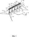
- Fig. 1 illustrates an ocean current turbine system 100 according to an embodiment of the invention.
- the ocean current turbine system 100 comprises a plurality of current turbines 110A-E and respective floating spar/towers 120A-E, each turbine 110 disposed on its own spar/tower 120.
- the spar/towers 120A-E are located (when in operation) between a top structural connecting member 130 above the water line "WL" and a bottom structural connecting member 140 below the water line.
- the top structural connecting member 130 can be either a truss, a beam, or other suitable structural element, the identification and implementation of which is apparent to one of ordinary skill in the art, to join spars/towers 120A-E together at one end.
- the top structural connecting member 130 is illustrated as a truss and therefore will be referred to as such in the remaining description even though other types of a structural connecting member may be used.
- the bottom structural connecting member 140 is a wing in a preferred embodiment.
- the bottom structural connecting member 140 can alternatively be a truss, beam, or other suitable structural element, the identification and implementation of which is apparent to one of ordinary skill in the art, to join spars/towers 120A-E together at the opposite end.
- the bottom structural connecting member 140 is illustrated as a wing and therefore will be referred to as such in the remaining description even though other types of a structural connecting member may be used.
- the towers 120A-E, truss 130, and wing 140 make a floating frame.
- the system 100 includes five turbines 110A-E; however any number (greater than one) of turbines 110 with respective spar/towers 120A-E may be implemented.
- the turbines 110A-E are located subsurface near the base of the towers 120A-E and horizontal wing 140. This permits the center of gravity of the system 100 to be located in the bottom one-third of the spar/towers 120A-E near the wing 140, while the center of buoyancy is located in the top third of the spar/towers 120A-E below the water line and near the truss structure 130.
- the entire system 100 floats vertically, with respect to the spar/towers, and appears as a horizontal ladder floating with one side above the water surface.
- the turbines 110A-E and spar/towers 120A-E are modular, which enables the system 100 to provide added turbine capacity by lengthening the truss 130 and the bottom wing 140.
- the turbines 110A-E may be located at the same relative height along the towers 120A-E or at different heights for added capacity per unit length of the frame.
- a turbine 110 may be moved coaxially up and down a respective spar/tower 120 along a track 125 by a motorized gear on the turbine base engaging with a linear gear along the track.
- the turbine may be moved coaxially up and down the spar/tower by cables and pulleys.
- worm gears, hydraulic pistons, or other means may also be used to drive a turbine 110 along the track 125.
- the turbine track/drive is herein referred to as the elevator.
- the truss 130 may include an optional crane 160 that can move along the length of the truss 130 to raise and lower turbines 110A-E, remove the rotor, and handle other components. Power generated by the system 100 may be carried via a power cable 161 to an electrical transfer station 170, the implementation of which is apparent to one of ordinary skill in the art.
- a turbine 110 may comprise fixed pitch blades or variable pitch blades. Blade spoilers may be optionally implemented to limit the amount of lift created by the blades.
- one or more of the turbines 120A-E may be located on a respective tower 120A-E downstream of the current flow.
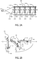
- Fig. 2A and 2B illustrates the transiting and deployment of the floating tower frame ocean current turbine system 100 to an operating site.
- towing e.g., by a boat 210 via towing lines 215
- the system 100 is allowed to float flat on the ocean surface, to clear shallow areas such as those near a quayside or other littoral area.
- upstream mooring lines are attached.
- an electric motor and drive gear housed within the turbine base engages a linear gear along the track, thus, the turbine 110 and its base slides coaxially along the track.
- the motor-gear arrangement drives the turbine on its base towards a collar 220A-E, which is aligned to receive the turbine base from the spar/tower track.
- turbines 110A-E move along the respective track 125A-E, toward the bottom end of the spar/tower 120A-E, the center of gravity of the entire frame shifts from the horizontal floating tower central position, used in transiting, to the lower end of the tower near the wing, causing the lower end to sink thereby rotating the frame from horizontal to vertical.
- This rotation of the frame may be assisted by ballast tanks (not shown) inside the base of the spa/towers 120A-E and/or in the wing 140, and which when flooded stabilizes the frame in its operational vertical position. For long-term overhaul, this rotation process is reversed for towing the system 100 back to quayside.
- the system 100 is moored to seabed anchor(s) with a number of mooring lines 150.
- mooring lines 150 are disposed at each end of the truss 130 and wing 140 as shown.
- mooring lines 150 may also be at intermittent points along the length of the truss and wing as the system 100 is made longer to accommodate the thrust load of more spar/towers and turbines.
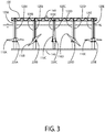
- Fig. 3 illustrates a front view of the floating spar/tower frame ocean current turbine system 100 in its operating position.
- Each turbine 110A-E and the connected turbine base moves along the track and collar yaw (TRAKYAW) system comprising tracks 125A-E and collars 220A-E attached to the towers 120A-E.
- TRAKYAW track and collar yaw
- a TRAKYAW system provides a means of turbine yawing, when in operation.
- the turbine 110 and its base 112 rides on the vertical track 125.
- the track 125 provides a means of raising the turbine to the truss 130 above the ocean surface for servicing. Once servicing is completed, a turbine 110 and its base 112 are lowered to the operating position.
- the turbine base 112 disengages the track 125 and engages a coupling arrangement similar to the track on the collar.
- the turbine 110 is able to yaw around the spar/tower 120 by a collar 220 around the spar/tower 120, on which it is connected.
- the turbine 110 is coupled to the turbine base 112 via a bearing 114.
- the tower 120 is laminated with low friction material such as teflon or low friction polymer coating on which the collar 220 rotates once it reaches its operating position. Other bearing methods may be used.
- the TRAKYAW system of Fig. 4 comprises hydraulic actuators or electric yaw motors 410 attached to the collar 220.
- the gears 412 of the yaw motors 410 mesh with a sun gear 420 girdling and connected to the spar/tower 120.
- Activation of yaw motors 410 rotate the turbine 110 and collar 220 against the sun gear 420 on the tower.
- yaw motor activation is controlled by a current flow direction sensor (not shown).
- a generator torque control sensor (not shown) may also activate the yaw motor 410.
- the turbine generator torque control sensor can detect current flow speeds in excesses of the generator system capacity.
- the turbine controller is programmed to activate the yaw system to reduce the rotor exposure to the flow, thus limiting the rotor torque to the generating system to stay within its rated loads.
- the following table presents the relationship between the percentage rotor flow exposure and degrees the rotors are off-axis to flow direction. Rotor Flow Exposure Degrees Off-Axis to Flow Direction 100% 0° 98% 10° 87% 20° 71% 45°
- This method of torque control benefits from using the yaw system for both yawing to squarely face the current to gain maximum current flow energy capture, while also providing a means of shedding current energy in excesses of the turbine's rated capacity. This is particularly important in tidal flows where the force of extreme flow speed must be mitigated to a productive and economic operation range for the turbine. Yawing "out of the flow” avoids variable pitch blades in a rotor prone to failures and high servicing requirements.
- Fig. 5 illustrates a cross-sectional view of the TRAKYAW system.
- the collar 220 including its turbine 110 can be rotated or yawed about the tower 120 thereby positioning the rotor blades to squarely face the current flow to optimize the power capture of the current.
- the collar 220 and respective turbine 110 can rotate 350 degrees about the vertical axis of the tower 120. In most tidal currents yawing would be in the range of 150° to 210°.
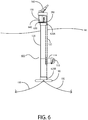
- Fig. 6 illustrates the side view of a turbine and spar/tower yawing system 600 according to an embodiment of the invention.
- the turbine yawing system 600 comprises a tower top connection to the truss 130 by a rotatable bearing 620A and a bottom of the tower connection to the wing 140 also by a rotatable bearing 620B.
- a sun gear 630 girdling the spar/tower top is driven as required by a yaw motor 640 mounted on the bottom of the truss.
- the track 125 also serves to access the turbine 110 to the operations deck 350 for servicing.
- the TRAKYAW system responds when the flow direction sensor detects a deviation in current direction.
- the system controller energizes the yaw motors 410 to make a turbine yaw position adjustment upstream of the spar/tower.
- the TRAKYAW system positions the rotor in the flow much quicker than a passive yaw system, thereby generating power earlier, for overall higher production. This is to be contrasted with a passive yaw system which requires the forces of the flow to yaw the turbine 110, moving it to a downstream position (from the tower). Passive yawing where the rotor is downstream of its support structure can result in damaging cyclic loads, since the rotor blades experience substantial stream flow impedance (shadowing) from a spar/tower, twice on each revolution.
- TRACKYAW The preceding TRACKYAW description applies to ocean current turbines operating in tidal flow regimes with periodic flow reversal.
- the current meanders and azimuth adjustments in the range of ⁇ 20° for the rotors to face the current are required.
- the 350° yawing of the individual turbines is not required and the yaw system function may be accomplished by changing the azimuth orientation of the frame as shown in Fig. 7 .
- the floating spar/tower frame ocean current turbine system 100 is viewed from the top looking down onto the ocean surface.
- An azimuth orientation change is accomplished using the mooring lines 150 at each end of the frame.
- the mooring lines 150 are instead run across or looped over a winch 107, which is controlled to adjust the upstream and downstream mooring line length to the frame, thus altering the heading of the frame.
- An optional second winch 107 can be used on the opposite side of the frame. This azimuth positioning control by winching the mooring line(s) 150 provides an alternative method of facing the rotors squarely to the current flow without the need for a yaw system on each turbine.
- Depth control of the current turbine system 100 is based on buoyancy of the towers 120A-E and hydrodynamic lift of the wing 140, offsetting the gravity force and downward force vector of the current creating drag on rotors and frame due to mooring to the ocean floor.
- the drag force from the current on the system 100, moored to the ocean floor has two force vectors: a horizontal (drag) force and a downward force.
- the downward force is compensated by the added volumetric displacement as the submerged portion of the spars/towers 120 increases, along with the hydrodynamic lift of the wing 140, resulting from the current.
- the greater the flow speed the greater the wing lift to offset the downward force component. This balance of upward and downward forces maintains the current turbine system 100 within the operating range of depth for optimum performance.
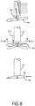
- Fig. 8 illustrates three alternative embodiments of the wing 140.
- the wing 140 comprises a hydrodynamic efficient wing in a fixed pitch position connected to the base of the towers 120A-E. This is preferable when operating in a current that flows with no flow reversal (such as the Florida Gulf Stream).
- the wing 140 can be fitted to pitch actively or passively.
- the wing 140 may vary its pitch relative to the spar/tower via an electromechanical or hydraulic activation control mechanism 810 at the base of the towers 120A-E.
- the control mechanism 810 actively controls the pitch of the wing 140.
- the pitch of the wing 140 is passively adjusted via a pivot arm 820, where drag of the current over a drag plate pitches the wing into a position to provide hydrodynamic lift. Adjusting the pitch of the wing 140 provides hydrodynamic lift to the ocean current turbine system 100 and compensates for the downward force vector induced by the current drag on the turbines and the frame moored to the ocean floor.
- a pivot arm 820 where drag of the current over a drag plate pitches the wing into a position to provide hydrodynamic lift.
- Adjusting the pitch of the wing 140 provides hydrodynamic lift to the ocean current turbine system 100 and compensates for the downward force vector induced by the current drag on the turbines and the frame moored to the ocean floor.
- the system 100 does not have a connection vessel floating on the surface creating unproductive drag across the current flow; rather, the turbine spar/towers 120A-E present the only ocean surface exposure, which due to their small volumetric displacement in a passing wave and the distance between the towers 120A-E, the hogging and sagging loads become minimal.
- the current turbine system 100 is designed to avoid loads caused by wave action. These specifically hogging and sagging loads of a surface vessel being lifted by a wave passing along its longitudinal center (hogging) or waves at each end of the wing resulting in reduced support at the center (sagging load).
- the current turbine system spar/towers extending through the ocean surface provide minimum exposure to wave "slap" loads.
- the current turbine system 100 requires far less structural material and can be made much larger providing a cost competitive advantage.
- a major cost component of ocean current generating systems is the power cable to shore and the mooring and anchoring. Therefore it is advantageous to have more turbines per system that can utilize the same mooring and anchoring, along with a single power cable.
- Fig. 9 illustrates the side view of a current turbine system 900 according to another embodiment of the invention.
- the box truss structure 130 spans the tops of the spars/towers 120 above the ocean surface and serves as a platform for service crews to board and maintain the turbines 110.
- the bottom of the box truss 130 is the operations deck 350 while its top serves as a track for the crane 160 to traverse the length of the truss 130 for accessing the turbines 110.
- the combination of the elevator TRAKYAW system 125 and the crane 160 enables each turbine 110 to be serviced on the operations deck 350 of the truss 130 under most weather and sea conditions. Power generation remains uninterrupted for the rest of the turbines 110B-E while a particular turbine 110A is being serviced.
- This equipment cabin 610 may also contain a hydrostatic motor (not shown) to drive an electric generator (not shown).
- the low speed (RPM), high torque of the turbine drives a hydrostatic pump (not shown) on a common shaft delivering high pressure hydraulic fluid to the hydrostatic motor driving the generator at high speed (RPM) for efficient power generation.
- Multiple turbine pumps may feed into a common manifold plumbed to the hydrostatic motor which drives the generator.
- the electric power is delivered from the generators via a submarine cable to a shore substation.
- the equipment cabin 610 may also contain a reverse osmosis membrane bank (not shown) whereby the turbines 110A-E drive a sea water pump (not shown) delivering high pressure seawater to the reverse osmosis membrane bank for delivery of fresh water by pipeline connection to a shore receiving station.
- a reverse osmosis membrane bank (not shown) whereby the turbines 110A-E drive a sea water pump (not shown) delivering high pressure seawater to the reverse osmosis membrane bank for delivery of fresh water by pipeline connection to a shore receiving station.
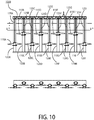
- Fig. 10 illustrates a floating spar/tower frame current turbine system 1000 according to another embodiment of the invention.
- the current turbine system 1000 comprises turbines 110A-I and towers 120A-I with TRAKYAWS 310, truss 130, wing 140, and a crane 160.
- the turbines 110A-I are offset from one another, i.e., odd turbines 110A, 110C, 110E, 110G, and 1101 are located closer to the wing 140 than even turbines 110B, 110D, 110F, and 110H.
- multiple rows of turbines 110 are disposed at varying depth.
- the spar/towers 120A-I are also offset from one another. Such a configuration increases the electric power generating capacity and number of turbines 110 per length of truss 130.
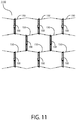
- Fig. 11 illustrates a current turbine farm 1100 according to an embodiment of the invention.
- a plurality of current turbine systems 100 (or 900, 1000) are placed in a honeycomb pattern as shown (looking down from above onto the ocean surface). Any number of current turbine systems 100 may be employed.
- the current turbine systems 100 are connected to one another via mooring lines 150 and shared anchors (shown by black dots).
- Fig. 12 illustrates a yawing spar turbine 1200 according to an embodiment of the invention.
- the turbine system 1200 comprises a floating spar buoy 1210, a spreader 1220 disposed on the spar 1210, a turbine drivetrain/generating system in a vessel 1230, and a service deck or platform 1240.
- the spar 1210 is cylindrical in shape.
- the diameter of the spar buoy 1210 decreases at its bottom end (or keel) 1212 starting at the location of the drivetrain/generator turbine vessel 1230.
- the keel 1212 houses a winch (not shown) that is connected to a vertical mooring line 1214.
- the winch maintains tension on the mooring line 1214, which is anchored to a seabed.
- the winch can also adjust the freeboard (depth) of the yawing spar turbine 1200 by taking in or letting out the mooring line 1214.
- Within the keel 1212 are one or more ballast tanks (not shown), the implementation of which is apparent to one of ordinary skill in the art.
- the ballast tanks may be used to adjust the buoyancy of the yawing spar turbine 1200 and keep it upright during operation and with the desired tension on the mooring line 1214.
- the spreader 1220 sits below the water line and comprises tips 1222 that serve as connections points for fore and aft cable yokes 1224, which transition to mooring lines 1225 connected to anchors (not shown) on the seabed.
- the anchors may be gravity anchors and/or suction pile anchors, or other types best suited to the seabed soil composition, the implementation of which are apparent to one of ordinary skill in the art.
- the turbine vessel 1230 comprises an upstream rotor 1232 having two or more fixed pitch blades or variable pitch blades 1234 (although only two are shown).
- the vessel 1230 contains drivetrain and generator (not shown) driven by the rotor 1232.
- Blade spoilers may be optionally implemented to limit the amount of lift created by the blades 1234.
- the blades 1234 rotate within the rotor plane producing rotation torque to drive a generator within the turbine vessel 1230, the implementation of which is apparent to one of ordinary skill in the art. Since currents generally flow faster near the surface, in slower flows the yawing spar turbine 1200 will operate closer to the surface, capturing the higher energy close to the surface.
- the yawing, spar turbine 1200 passively adjusts its operating depth through rotor drag whereby higher flow speed results in more rotor drag driving spar and turbine deeper by the downward force vector of the mooring system. This results in the yawing spar turbine 1200 capturing more energy in a tidal flow by adjusting the operating depth to the turbine's rated capacity.
- the spar 1210 and the turbine vessel 1230 are able to rotate (yaw) relative to stationary spreader 1220.
- exemplary yawing of the spar 1210, the turbine vessel 1230, and the rotor blades 1234 are shown.
- the rotor blades 1234 and vessel (drivetrain and generator) 1230 are oriented for the rotor to face the flow direction of the current.
- the rotor 1232 and vessel 1230 has rotated forty-five (45) degrees relative to the spreader 1220.
- the spar 1210 and rotor 1232 has rotated a further ninety (90) degrees and one hundred and thirty five (135) degrees respectively relative to the spreader 1220.
- the spar 1210, vessel 1230 and rotor 1232 rotate (yaw) together three hundred and sixty (360) degrees in either direction relative to the spreader and mooring lines and, this way, the rotor 1232 is always positioned to face the current as the current direction reverses or the current meanders in the same direction.
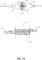
- rotation/yawing of the spar 1210 along with the turbine 1230 is accomplished through one or more yaw motors (not shown) housed within the spreader 1220.
- a ring gear 1216 is fixed on the outside surface of the spar 1210.
- Actuation of the yaw motors drive gears 1226, which engage the ring gear 1216 to rotate the spar buoy 1210 relative to the spreader 1220.
- a current flow direction sensor (not shown) is included to detect changes in flow direction.
- the yaw motors are automatically activated in order to adjust the orientation of the spar 1210 and rotor 1232 relative to the spreader 1220, thereby ensuring that at all times, the rotor plane properly faces the direction of current or tidal flow. For example, if the direction of the water flow changes by forty-five (45) degrees, the spar 1210 and rotor 1232 are rotated forty-five (45) degrees in the direction of the flow to ensure the rotor plane properly faces the new current flow.
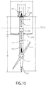
- Fig. 15 illustrates the yawing spar turbine 1200 according to an exemplary embodiment of the invention.
- the height of the spar 1210 (from keel 1212 to platform 1240) is twenty-five (25) meters.
- the diameter at its maximum girth is two (2) meters.
- the platform 1240 spans four (4) meters and sits five (5) meters above the water line.
- the spreader 1220 spans eleven (11) meters and the spreader 1220 sits three (3) meters below the water line.
- an outer hatch 1250, one or more optional ladders 1252, and one or more optional inner hatches 1254 to allow servicing of a drivetrain and generating equipment.
- a crane 1260 for raising or lowering heavy parts within the spar 1210.
- Fig. 16 illustrates deployment of the yawing spar turbine 1200 according to an embodiment of the invention.
- the yawing spar platform 1200 is towed in a horizontal position by the winch mooring line 1214 and the spreader yoke cables.
- the yokes 1224 are connected to the forward and aft mooring lines 1225 and the winch line 1214 is connected to a gravity anchor (not shown).
- the winch inside the keel 1212 draws the bottom end of the spar 1210 down and may be assisted by flooding of ballast tanks in the keel 1212 to reach a vertical position (shown in shading). The winch is then locked to retain a desired operating depth, or can actively control operating depth in areas of wide tide level range.
Landscapes
- Engineering & Computer Science (AREA)
- Chemical & Material Sciences (AREA)
- Combustion & Propulsion (AREA)
- Mechanical Engineering (AREA)
- General Engineering & Computer Science (AREA)
- Life Sciences & Earth Sciences (AREA)
- General Life Sciences & Earth Sciences (AREA)
- Oceanography (AREA)
- Power Engineering (AREA)
- Other Liquid Machine Or Engine Such As Wave Power Use (AREA)
Description
- The present invention is directed to turbine systems for the generation of electrical power and/or the production of fresh water from ocean tidal and/or current (gyre) flows, and more specifically, to a floating, yawing spar tidal turbine.
- Ocean currents are a major, largely untapped energy resource. The potential for ocean current electric power generation in the United States is as much as 185 TWh/yr., comprising both tidal and gyre currents, which have the advantage of delivering clean, renewable, predictable power to the coastal transmission grid, which are usually in close proximity to high load centers. Research and development in this area is driven by the need to generate electricity from renewable energy resources, particularly in view of the rising level of CO2 and methane in the earth's atmosphere from the combustion of carbon fuels and the resulting disruptive impact on climate from global warming.
- An ocean current is a continuous, directed movement of seawater generated by the forces acting upon this flow, such as breaking waves, wind, Coriolis effect, evaporation, temperature, salinity differences, and tides caused by the gravitational pull of the Moon and the Sun. Depth contours, shoreline configurations and interaction with other currents influence a current's direction and strength. Ocean gyre currents are relatively constant and near our coastlines, generally flow in one direction, in contrast to periodic tidal currents that reverse in flow direction due to gravitational forces. Harnessing a slow moving fluid to generate power has been effectively accomplished with wind turbines. While ocean currents move slowly relative to typical wind speeds, they carry a great deal more energy because of the density of water, which is more than 800 times that of air. The following table illustrates the average electrical power density as a function of wind or current flow speeds for a wind turbine or marine turbine, respectively.
Wind Turbine Marine Turbine Average Wind Speed (typical range - m/s) Average Power Density W/m2 Average Flow Speed (typical range - m/s) Average Power Density W/m2 6.0 132 0.99 498 7.5 258 1.20 886 8.5 376 1.43 1500 10.0 613 1.60 2101 - With gyre currents, the constancy of flow also provides the opportunity for steady electric power delivery, compared to the intermittency of wind and solar. Because of these physical properties, ocean currents contain an enormous amount of energy that can be captured and converted to a usable form.
- The United States, United Kingdom, Japan, and other countries are pursuing ocean current energy. Wind turbine technology is mature and generally adaptable to marine conditions, therefore the principal challenge to economically harnessing currents has been with the turbine platform topology and its station holding approach. For wide commercial deployment, turbines must be easy to transport, install, have accessibility to the turbine power deck for operations and maintenance, and generate power with levelized cost of energy (LCOE) comparable to wind turbines and photovoltaic systems.
- For ocean current energy to be utilized successfully on a commercial scale, a number of engineering and technical challenges need to be addressed, including: avoidance of blade cavitation (bubble formation); prevention of marine growth buildup; reliability (since at-sea maintenance costs are potentially high); efficient methods of deployment; corrosion resistance; and anchoring and mooring methods. System reliability is of particular importance, since the logistics of at-sea maintenance is limited by accessibility, in windows of acceptable weather and sea-states, adding to the costs of maintenance services. Any system deployed in the ocean must be able to survive extreme waves and storms, which raises the capital cost and maintenance, and have minimal impact on the marine environment, such as fishing grounds, beach shoreline, and be compatible with ocean navigation.
- Korean Patent No.
936907 -
U.S. Patent No. 7,307,356 to Fraenkel discloses a dual rotor marine current turbine mounted on the ocean floor. This system is also expensive due to structural requirements to deal with the overturning of the whole structure resulting from thrust load of the current on the rotors. Also, installation and securing to the ocean floor is only possible during short periods of time between tidal flows. Rotors and support structure can be raised for servicing, however all power generation is shut down if only one rotor requires servicing. Rotors and their support structure do not yaw. Rather, the blades reverse direction for change in tidal flow direction. This means that the rotors are not squarely facing the flow when the flow in one direction is a little different than the flow in the opposing direction resulting in reduced power production. - Great
Britain Patent No. 2,447,774 to Fraenkel WO 2005/040604 A2 discloses a floating power generation assembly which comprises at least three floating units floating on a body of water, and at least three anchors secured to a solid surface beneath the body of water. Each of the floating units is provided with power generation means. Further, the floating units are arranged substantially at the vertices of at least one equilateral triangle. Furthermore,DE 10 2008 029982 A1 discloses a stabilization and maintenance device for rope tensioned carrier device for e.g. wind energy plant. Moreover, inUS 2010/074750 A1 a device for production of energy from currents in water is disclosed. The device comprises a first element, a second element and a plurality of turbine modules connected to the first element. The second element is mounted on the first element in an approximately perpendicular relationship. Further, the first element is adapted for submersion below a water surface. An upper part of the second element projects up above the water surface when the plant is in production. - In summary, known prior art systems are not capable of producing cost-effective, utility-scale electrical power output to meet modern energy needs. What is needed is a system for efficiently capturing power from ocean or tidal currents, to generate electric power or produce desalinated water, which is cost effective to manufacture, deploy, and maintain.
- The present invention overcomes these and other deficiencies of the prior art by providing a novel floating, yawing spar platform for a turbine generating system according to appended
claim 1. The yawing, spar platform includes a spreader located above the rotor with the tips of the spreader serving as connections points, for the fore and aft cable yokes, which transition to fore and aft mooring lines connected to anchors on the seabed. The spreader contains one or more yaw motors driving gears, which engage with a ring gear on the outer perimeter of the spar. As tidal direction changes the spreader is held in a fixed position by the mooring lines and yokes. The entire spar and turbine are yawed against the fixed spreader to maintain the rotor plane facing the tidal flow. Flow direction sensors on the platform activate the yaw motor for automatic yaw adjustments to flow direction. The bottom end ("the keel") of the spar extends to approximately the bottom sweep of the rotor plane and contains a winched vertical mooring line, extending to the seabed and attached to a gravity or suction pile anchor. The turbine drive train deck can be accessed from the surface deck, via hatches and ladders within the spar. Deployment is performed by towing the spar turbine in a horizontal position by the winch mooring line and the spreader yoke cables. At the operating site, the yokes are connected to the forward and aft mooring lines and the winch line is connected to a gravity anchor. The winch inside the keel draws the bottom end of the spar down and may be assisted by flooding ballast tanks in the keel to reach a vertical position for the spar. The winch is then locked to retain required operating depth, or can be used to actively control operating depth in areas of wide tide level range. - In an embodiment of the invention, a current or tidal turbine comprises: a floating spar buoy including a keel at a bottom end; a spreader disposed on the spar, wherein the spreader comprises connection points for attaching one or more mooring lines connected to one or more anchors; the spreader may further comprise a yaw motor to react the spreader against the spar to effect yawing, and turbine and its power generating system disposed in a vessel integrated with the spar for converting current or tidal flow into electricity. A current or tidal flow direction sensor activates the yaw motor in response to a change in current or tidal flow direction. The spar may include a plurality of rotors within a rotor plane and the yaw motor rotates the floating spar about a vertical axis to maintain the rotor plane facing the current or tidal flow direction. The keel extends to the bottom of the rotor sweep and downstream of the operating rotor plane, and may comprise a winch attached to a vertical mooring line. The keel avoids any entanglement by the rotor with the vertical mooring line. The keel may further include a ballast tank. The spar buoy platform floats in a horizontal plane during towing to an operating site. Flooding of the ballast tank and activation of the winch draws the keel down and rotates the yawing spar platform into a vertical position. The operating depth from the ocean surface of the current or tidal turbine rotor is adjusted through the winch and helps maintain the rotor plane in a vertical position when under the thrust load of the current. The floating spar includes a hatch on the top deck above the waterline and internal ladders to permit serviceman access to the drivetrain, the electrical equipment, and the controls of the turbine.
- In another embodiment of the invention, a current or tidal turbine comprises: a cylindrical floating spar, a turbine and drivetrain/power generating system within a vessel integrated with the cylindrical floating spar, a sensor for sensing a direction of water flow across the cylindrical floating spar, a spreader on the spar above the rotor, and a yaw motor fixed to the spreader to position the turbine in the sensed direction of water flow. In operation of the turbine, the cylindrical floating spar floats vertically with its top approximately ten to twenty percent (10-20%) above the water line and its bottom approximately eighty to ninety percent (80-90%) below the water line. The center of gravity of the current or tidal turbine is located below its center of buoyancy. A winch is located at a bottom end of the spar within the keel and is attached to a mooring line extending to the seabed. The spreader structure lateral ends are fixed to fore and aft cable yokes. The fore and aft cable yokes connect to mooring lines with anchors on the seabed. The spreader houses the yaw motor(s) and further comprises driving gears engaging a ring gear on an outer perimeter of the spar. The platform has a current flow direction sensor to activate the spar yawing system. The turbine rotor comprises variable pitch blades, which can be activated to shed the force of the current speed in excess of the system's rated power and to feather the blades completely for a safe shutdown of the machine. The turbine is serviced by personnel through an entrance hatch on the spar above the water line and a decent on ladders internal to the spar and to the drivetrain deck.
- This present invention has significant advantages over existing tidal current turbines. First, currents are often relatively turbulent and flow faster closer toward the surface. Certain tidal turbines are mounted rigidly on the seabed and they are not able to operate in the higher, more energetic flow speeds near the surface. Furthermore, rigidly mounted structures require greater structural margins, which have significantly higher costs. The yawing spar turbine platform of the present invention floats with a portion of the spar above the water surface, but is resiliently stationed by mooring cables and can therefore flex to mitigate higher loads from wave turbulence and unusually higher speeds in the flow. Second, the cost of seabed mounted turbines can be extremely high due to the massive structure and foundation required, short windows of nil flow (still water) and the complexities and costs of underwater construction requiring specialized ships and cranes. The spar turbine of the present invention utilizes conventional anchoring systems providing substantial cost savings compared to seabed mounted. Third, the turbine of the present invention captures more energy in the tidal flow by passively adjusting its operating depth by means of rotor drag. As the tides change direction, the flow slows and virtually stops, then the counter flow starts to increase. With minimum flow the spar turbine is closer to the surface, since the rotor drag is less and the machine captures whatever energy is yielded in that flow. As the flow velocity increases, the rotor drag increases, and the mooring to the seabed creates a downward force which causes the spar buoy to reach a depth where the downward force of the moored rotor drag equals the upward force of the platform buoyancy. Higher flow speed results in more rotor drag driving the buoyant spar deeper. In this manner, the turbine operates more of the time in its design capacity range, than a turbine vertically fixed in the flow. Fourth, in certain prior art, a vessel on the surface rotates multiple arms with turbines, down below the surface to a vertical rotor operating position. Since this vessel operates on the surface this precludes adjusting the rotor depth to the current velocity for gains in turbine power production. The surface vessel is also subjected to extreme forces of high seas and turbulent wave action. The yawing spar turbine of the present invention has the special properties of a spar buoy where small ocean surface area is penetrated by the cylindrical spar structure, ideal for minimizing wave loading. The small surface area coupled with the mass of the spar turbine results in minimal heave of the system and stresses on the structure in destructive wave environments, allowing for a lighter structure with lower costs.
- The foregoing, and other features and advantages of the invention, will be apparent from the following, more particular description of the preferred embodiments of the invention, the accompanying drawings, and the claims.
- For a more complete understanding of the present invention, the objects and advantages thereof, reference is now made to the ensuing descriptions taken in connection with the accompanying drawings briefly described as follows.
-
Fig. 1 illustrates an ocean current turbine system according to an embodiment of the invention; -
Fig. 2A and 2B illustrates transportation and deployment of the ocean current turbine system ofFig. 1 to an operating site; -
Fig. 3 illustrates a front view of the ocean current turbine system ofFig. 1 in its operating position; -
Fig. 4 illustrates a track and collar yaw (TRAKYAW) system attached to a tower according to an embodiment of the invention; -
Fig. 5 illustrates a cross-sectional view of the TRAKYAW system ofFig. 4 ; -
Fig. 6 illustrates a turbine and tower yawing system according to an embodiment of the invention; -
Fig. 7 illustrates a system for changing the azimuth orientation of the ocean current turbine system ofFig. 1 ; -
Fig. 8 illustrates three alternative embodiments of the wing ofFig. 1 ; -
Fig. 9 illustrates a side view of the movement of a turbine system according to an embodiment of the invention; -
Fig. 10 illustrates an ocean current turbine system according to another embodiment of the invention; -
Fig. 11 illustrates a turbine farm utilizing the ocean current turbine system ofFig. 1 according to an embodiment of the invention; -
Fig. 12 illustrates a yawing spar turbine according to an embodiment of the invention; -
Fig. 13 illustrates exemplary 180 degree yawing of the spar and turbine as the spreader remains stationary; -
Fig. 14 illustrates a gearing mechanism by which the spreader and turbine are rotated relative to the stationary spreader of the yawing spar turbine ofFig. 12 ; -
Fig. 15 illustrates the yawing spar turbine interior decks and hatches according to an exemplary embodiment of the invention; and -
Fig. 16 illustrates deployment of the yawing spar turbine ofFig. 12 according to an embodiment of the invention. - Preferred embodiments of the present invention and their advantages may be understood by referring to
Figs. 1-16 , wherein like reference numerals refer to like elements. The present invention may be utilized in any type of moving liquid, e.g., water flow, environment such as, but not limited an ocean current environment or tidal current environment. Although the present invention is described in the context of electrical power generation, it can also be used to provide high pressure seawater for reverse osmosis fresh water production. -
Fig. 1 illustrates an oceancurrent turbine system 100 according to an embodiment of the invention. The oceancurrent turbine system 100 comprises a plurality ofcurrent turbines 110A-E and respective floating spar/towers 120A-E, eachturbine 110 disposed on its own spar/tower 120. The spar/towers 120A-E are located (when in operation) between a top structural connectingmember 130 above the water line "WL" and a bottom structural connectingmember 140 below the water line. The top structural connectingmember 130 can be either a truss, a beam, or other suitable structural element, the identification and implementation of which is apparent to one of ordinary skill in the art, to join spars/towers 120A-E together at one end. As shown, the top structural connectingmember 130 is illustrated as a truss and therefore will be referred to as such in the remaining description even though other types of a structural connecting member may be used. The bottom structural connectingmember 140 is a wing in a preferred embodiment. However, the bottom structural connectingmember 140 can alternatively be a truss, beam, or other suitable structural element, the identification and implementation of which is apparent to one of ordinary skill in the art, to join spars/towers 120A-E together at the opposite end. As shown, the bottom structural connectingmember 140 is illustrated as a wing and therefore will be referred to as such in the remaining description even though other types of a structural connecting member may be used. Thetowers 120A-E,truss 130, andwing 140 make a floating frame. - As shown, the
system 100 includes fiveturbines 110A-E; however any number (greater than one) ofturbines 110 with respective spar/towers 120A-E may be implemented. In operation, theturbines 110A-E are located subsurface near the base of thetowers 120A-E andhorizontal wing 140. This permits the center of gravity of thesystem 100 to be located in the bottom one-third of the spar/towers 120A-E near thewing 140, while the center of buoyancy is located in the top third of the spar/towers 120A-E below the water line and near thetruss structure 130. When in operating position, theentire system 100 floats vertically, with respect to the spar/towers, and appears as a horizontal ladder floating with one side above the water surface. In an embodiment of the invention, theturbines 110A-E and spar/towers 120A-E are modular, which enables thesystem 100 to provide added turbine capacity by lengthening thetruss 130 and thebottom wing 140. Theturbines 110A-E may be located at the same relative height along thetowers 120A-E or at different heights for added capacity per unit length of the frame. - As further discussed below, a
turbine 110 may be moved coaxially up and down a respective spar/tower 120 along atrack 125 by a motorized gear on the turbine base engaging with a linear gear along the track. Alternatively, the turbine may be moved coaxially up and down the spar/tower by cables and pulleys. Still alternatively, worm gears, hydraulic pistons, or other means may also be used to drive aturbine 110 along thetrack 125. The turbine track/drive is herein referred to as the elevator. Thetruss 130 may include anoptional crane 160 that can move along the length of thetruss 130 to raise andlower turbines 110A-E, remove the rotor, and handle other components. Power generated by thesystem 100 may be carried via apower cable 161 to anelectrical transfer station 170, the implementation of which is apparent to one of ordinary skill in the art. - In an embodiment of the invention, a
turbine 110 may comprise fixed pitch blades or variable pitch blades. Blade spoilers may be optionally implemented to limit the amount of lift created by the blades. In an alternative embodiment of the invention, one or more of theturbines 120A-E may be located on arespective tower 120A-E downstream of the current flow. -
Fig. 2A and 2B illustrates the transiting and deployment of the floating tower frame oceancurrent turbine system 100 to an operating site. In towing (e.g., by aboat 210 via towing lines 215) to an operating site as shown inFig. 2A (viewed from above and looking down on the ocean), thesystem 100 is allowed to float flat on the ocean surface, to clear shallow areas such as those near a quayside or other littoral area. Once at the operating site as shown inFig. 2B (which is a side view looking at the end of the system 100), upstream mooring lines (not shown) are attached. When ready for installation of the frame at the operating site, an electric motor and drive gear housed within the turbine base engages a linear gear along the track, thus, theturbine 110 and its base slides coaxially along the track. The motor-gear arrangement drives the turbine on its base towards acollar 220A-E, which is aligned to receive the turbine base from the spar/tower track. Asturbines 110A-E move along therespective track 125A-E, toward the bottom end of the spar/tower 120A-E, the center of gravity of the entire frame shifts from the horizontal floating tower central position, used in transiting, to the lower end of the tower near the wing, causing the lower end to sink thereby rotating the frame from horizontal to vertical. This rotation of the frame may be assisted by ballast tanks (not shown) inside the base of the spa/towers 120A-E and/or in thewing 140, and which when flooded stabilizes the frame in its operational vertical position. For long-term overhaul, this rotation process is reversed for towing thesystem 100 back to quayside. Thesystem 100 is moored to seabed anchor(s) with a number of mooring lines 150. For example,mooring lines 150 are disposed at each end of thetruss 130 andwing 140 as shown. Optionally,mooring lines 150 may also be at intermittent points along the length of the truss and wing as thesystem 100 is made longer to accommodate the thrust load of more spar/towers and turbines. -
Fig. 3 illustrates a front view of the floating spar/tower frame oceancurrent turbine system 100 in its operating position. Eachturbine 110A-E and the connected turbine base moves along the track and collar yaw (TRAKYAW)system comprising tracks 125A-E andcollars 220A-E attached to thetowers 120A-E. As shown in more detail inFig. 4 , a TRAKYAW system provides a means of turbine yawing, when in operation. Theturbine 110 and itsbase 112 rides on thevertical track 125. Thetrack 125 provides a means of raising the turbine to thetruss 130 above the ocean surface for servicing. Once servicing is completed, aturbine 110 and itsbase 112 are lowered to the operating position. At thecollar 220, theturbine base 112 disengages thetrack 125 and engages a coupling arrangement similar to the track on the collar. In this position, theturbine 110 is able to yaw around the spar/tower 120 by acollar 220 around the spar/tower 120, on which it is connected. Theturbine 110 is coupled to theturbine base 112 via abearing 114. In an embodiment of the invention, thetower 120 is laminated with low friction material such as teflon or low friction polymer coating on which thecollar 220 rotates once it reaches its operating position. Other bearing methods may be used. - The TRAKYAW system of
Fig. 4 comprises hydraulic actuators orelectric yaw motors 410 attached to thecollar 220. Thegears 412 of theyaw motors 410 mesh with asun gear 420 girdling and connected to the spar/tower 120. Activation ofyaw motors 410 rotate theturbine 110 andcollar 220 against thesun gear 420 on the tower. In an embodiment of the invention, yaw motor activation is controlled by a current flow direction sensor (not shown). A generator torque control sensor (not shown) may also activate theyaw motor 410. The turbine generator torque control sensor can detect current flow speeds in excesses of the generator system capacity. The turbine controller is programmed to activate the yaw system to reduce the rotor exposure to the flow, thus limiting the rotor torque to the generating system to stay within its rated loads. The following table presents the relationship between the percentage rotor flow exposure and degrees the rotors are off-axis to flow direction.Rotor Flow Exposure Degrees Off-Axis to Flow Direction 100% 0° 98% 10° 87% 20° 71% 45° - This method of torque control benefits from using the yaw system for both yawing to squarely face the current to gain maximum current flow energy capture, while also providing a means of shedding current energy in excesses of the turbine's rated capacity. This is particularly important in tidal flows where the force of extreme flow speed must be mitigated to a productive and economic operation range for the turbine. Yawing "out of the flow" avoids variable pitch blades in a rotor prone to failures and high servicing requirements.
-
Fig. 5 illustrates a cross-sectional view of the TRAKYAW system. When in operation, thecollar 220 including itsturbine 110 can be rotated or yawed about thetower 120 thereby positioning the rotor blades to squarely face the current flow to optimize the power capture of the current. In an embodiment of the invention, thecollar 220 andrespective turbine 110 can rotate 350 degrees about the vertical axis of thetower 120. In most tidal currents yawing would be in the range of 150° to 210°. -
Fig. 6 illustrates the side view of a turbine and spar/tower yawing system 600 according to an embodiment of the invention. Here, theturbine yawing system 600 comprises a tower top connection to thetruss 130 by arotatable bearing 620A and a bottom of the tower connection to thewing 140 also by a rotatable bearing 620B. In this configuration there is no collar, and in operation, theturbine 110 and its base, are at the lower end of thetrack 125. For yawing the spar/tower and turbine, asun gear 630 girdling the spar/tower top is driven as required by ayaw motor 640 mounted on the bottom of the truss. In this configuration theentire tower 120 andturbine 110 yaws for the rotor to squarely face the flow. Thetrack 125 also serves to access theturbine 110 to theoperations deck 350 for servicing. - The TRAKYAW system responds when the flow direction sensor detects a deviation in current direction. The system controller energizes the
yaw motors 410 to make a turbine yaw position adjustment upstream of the spar/tower. The TRAKYAW system positions the rotor in the flow much quicker than a passive yaw system, thereby generating power earlier, for overall higher production. This is to be contrasted with a passive yaw system which requires the forces of the flow to yaw theturbine 110, moving it to a downstream position (from the tower). Passive yawing where the rotor is downstream of its support structure can result in damaging cyclic loads, since the rotor blades experience substantial stream flow impedance (shadowing) from a spar/tower, twice on each revolution. - The preceding TRACKYAW description applies to ocean current turbines operating in tidal flow regimes with periodic flow reversal. In areas where the current usually flows in steady direction with no flow reversal, there may be times when the current meanders and azimuth adjustments in the range of ±20° for the rotors to face the current are required. Under these conditions, the 350° yawing of the individual turbines is not required and the yaw system function may be accomplished by changing the azimuth orientation of the frame as shown in
Fig. 7 . Here, the floating spar/tower frame oceancurrent turbine system 100 is viewed from the top looking down onto the ocean surface. An azimuth orientation change is accomplished using themooring lines 150 at each end of the frame. Rather than being permanently secured to the frame, themooring lines 150 are instead run across or looped over awinch 107, which is controlled to adjust the upstream and downstream mooring line length to the frame, thus altering the heading of the frame. An optionalsecond winch 107 can be used on the opposite side of the frame. This azimuth positioning control by winching the mooring line(s) 150 provides an alternative method of facing the rotors squarely to the current flow without the need for a yaw system on each turbine. - Depth control of the
current turbine system 100 is based on buoyancy of thetowers 120A-E and hydrodynamic lift of thewing 140, offsetting the gravity force and downward force vector of the current creating drag on rotors and frame due to mooring to the ocean floor. The drag force from the current on thesystem 100, moored to the ocean floor has two force vectors: a horizontal (drag) force and a downward force. The downward force is compensated by the added volumetric displacement as the submerged portion of the spars/towers 120 increases, along with the hydrodynamic lift of thewing 140, resulting from the current. The greater the flow speed, the greater the wing lift to offset the downward force component. This balance of upward and downward forces maintains thecurrent turbine system 100 within the operating range of depth for optimum performance. -
Fig. 8 illustrates three alternative embodiments of thewing 140. As shown in the bottom illustration, thewing 140 comprises a hydrodynamic efficient wing in a fixed pitch position connected to the base of thetowers 120A-E. This is preferable when operating in a current that flows with no flow reversal (such as the Florida Gulf Stream). However, in a tidal current, thewing 140 can be fitted to pitch actively or passively. For example, as shown in the center illustration, thewing 140 may vary its pitch relative to the spar/tower via an electromechanical or hydraulicactivation control mechanism 810 at the base of thetowers 120A-E. Here, thecontrol mechanism 810 actively controls the pitch of thewing 140. As shown in the top illustration, the pitch of thewing 140 is passively adjusted via apivot arm 820, where drag of the current over a drag plate pitches the wing into a position to provide hydrodynamic lift. Adjusting the pitch of thewing 140 provides hydrodynamic lift to the oceancurrent turbine system 100 and compensates for the downward force vector induced by the current drag on the turbines and the frame moored to the ocean floor. One of ordinary skill in the art readily appreciates that the structure of awing 140 can be altered before deployment to change its hydrodynamic performance. - The
system 100 does not have a connection vessel floating on the surface creating unproductive drag across the current flow; rather, the turbine spar/towers 120A-E present the only ocean surface exposure, which due to their small volumetric displacement in a passing wave and the distance between thetowers 120A-E, the hogging and sagging loads become minimal. Thecurrent turbine system 100 is designed to avoid loads caused by wave action. These specifically hogging and sagging loads of a surface vessel being lifted by a wave passing along its longitudinal center (hogging) or waves at each end of the wing resulting in reduced support at the center (sagging load). The current turbine system spar/towers extending through the ocean surface provide minimum exposure to wave "slap" loads. - Current shear typically has the highest flow velocity at the surface, dropping to near zero at the ocean floor. A vessel floating on the surface at a cross angle to the current would require massive mooring and anchoring capacity due to drag along the length of the vessel. This not a problem with the current invention since the
current turbine system 100 has only the spar/towers below the surface and thelow drag wing 140 at the bottom of the spar/towers 120A-E. Therefore the principal drag of thesystem 100 is from the rotors thereby harnessing the power in the flow and reducing the mooring and anchoring structural requirements. - In this reduced surface exposure design, the
current turbine system 100 requires far less structural material and can be made much larger providing a cost competitive advantage. A major cost component of ocean current generating systems is the power cable to shore and the mooring and anchoring. Therefore it is advantageous to have more turbines per system that can utilize the same mooring and anchoring, along with a single power cable. -
Fig. 9 illustrates the side view of acurrent turbine system 900 according to another embodiment of the invention. Thebox truss structure 130 spans the tops of the spars/towers 120 above the ocean surface and serves as a platform for service crews to board and maintain theturbines 110. The bottom of thebox truss 130 is theoperations deck 350 while its top serves as a track for thecrane 160 to traverse the length of thetruss 130 for accessing theturbines 110. The combination of theelevator TRAKYAW system 125 and thecrane 160 enables eachturbine 110 to be serviced on theoperations deck 350 of thetruss 130 under most weather and sea conditions. Power generation remains uninterrupted for the rest of theturbines 110B-E while aparticular turbine 110A is being serviced. - Located on the
operations deck 350 of thetruss 130 is an equipment cabin 610 containing electric power conditioning equipment (not shown), This equipment cabin 610 may also contain a hydrostatic motor (not shown) to drive an electric generator (not shown). In this embodiment of the invention, the low speed (RPM), high torque of the turbine, drives a hydrostatic pump (not shown) on a common shaft delivering high pressure hydraulic fluid to the hydrostatic motor driving the generator at high speed (RPM) for efficient power generation. Multiple turbine pumps may feed into a common manifold plumbed to the hydrostatic motor which drives the generator. The electric power is delivered from the generators via a submarine cable to a shore substation. - In another embodiment of the invention, the equipment cabin 610 may also contain a reverse osmosis membrane bank (not shown) whereby the
turbines 110A-E drive a sea water pump (not shown) delivering high pressure seawater to the reverse osmosis membrane bank for delivery of fresh water by pipeline connection to a shore receiving station. -
Fig. 10 illustrates a floating spar/tower framecurrent turbine system 1000 according to another embodiment of the invention. Here, thecurrent turbine system 1000 comprisesturbines 110A-I and towers 120A-I with TRAKYAWS 310,truss 130,wing 140, and acrane 160. Theturbines 110A-I are offset from one another, i.e.,odd turbines wing 140 than eventurbines turbines 110 are disposed at varying depth. As shown in the cross-sectional view AA, the spar/towers 120A-I are also offset from one another. Such a configuration increases the electric power generating capacity and number ofturbines 110 per length oftruss 130. -
Fig. 11 illustrates acurrent turbine farm 1100 according to an embodiment of the invention. Here, a plurality of current turbine systems 100 (or 900, 1000) are placed in a honeycomb pattern as shown (looking down from above onto the ocean surface). Any number ofcurrent turbine systems 100 may be employed. Thecurrent turbine systems 100 are connected to one another viamooring lines 150 and shared anchors (shown by black dots). - Due to the multiple turbines in the embodiments discussed above, its structure may require wider quayside access and more vessels to deploy. Furthermore, the multiple interconnected rotors and tower require substantial structural mass to withstand the loads imposed by high wave states. This has led to the yawing spar tidal turbine design described below where the multiple tower frame structure is eliminated and a single spar and turbine, yawing against a stationary spreader on the spar, provides simplicity of structure, ease of deployment, resiliency to extreme sea state loads, and accessibility for operation and maintenance functions.
-
Fig. 12 illustrates a yawingspar turbine 1200 according to an embodiment of the invention. Here, theturbine system 1200 comprises a floatingspar buoy 1210, aspreader 1220 disposed on thespar 1210, a turbine drivetrain/generating system in avessel 1230, and a service deck orplatform 1240. Thespar 1210 is cylindrical in shape. In an optional embodiment of the invention, the diameter of thespar buoy 1210 decreases at its bottom end (or keel) 1212 starting at the location of the drivetrain/generator turbine vessel 1230. At its lowermost portion, thekeel 1212 houses a winch (not shown) that is connected to avertical mooring line 1214. The winch maintains tension on themooring line 1214, which is anchored to a seabed. The winch can also adjust the freeboard (depth) of the yawingspar turbine 1200 by taking in or letting out themooring line 1214. Within thekeel 1212 are one or more ballast tanks (not shown), the implementation of which is apparent to one of ordinary skill in the art. The ballast tanks may be used to adjust the buoyancy of the yawingspar turbine 1200 and keep it upright during operation and with the desired tension on themooring line 1214. During operation, thespreader 1220 sits below the water line and comprisestips 1222 that serve as connections points for fore andaft cable yokes 1224, which transition tomooring lines 1225 connected to anchors (not shown) on the seabed. The anchors may be gravity anchors and/or suction pile anchors, or other types best suited to the seabed soil composition, the implementation of which are apparent to one of ordinary skill in the art. - The
turbine vessel 1230 comprises anupstream rotor 1232 having two or more fixed pitch blades or variable pitch blades 1234 (although only two are shown). Thevessel 1230 contains drivetrain and generator (not shown) driven by therotor 1232. Blade spoilers may be optionally implemented to limit the amount of lift created by theblades 1234. In response to a current or tidal flow, theblades 1234 rotate within the rotor plane producing rotation torque to drive a generator within theturbine vessel 1230, the implementation of which is apparent to one of ordinary skill in the art. Since currents generally flow faster near the surface, in slower flows the yawingspar turbine 1200 will operate closer to the surface, capturing the higher energy close to the surface. In an embodiment of the invention, the yawing,spar turbine 1200 passively adjusts its operating depth through rotor drag whereby higher flow speed results in more rotor drag driving spar and turbine deeper by the downward force vector of the mooring system. This results in the yawingspar turbine 1200 capturing more energy in a tidal flow by adjusting the operating depth to the turbine's rated capacity. - In an embodiment of the invention, the
spar 1210 and theturbine vessel 1230 are able to rotate (yaw) relative tostationary spreader 1220. Referring toFig. 13 , exemplary yawing of thespar 1210, theturbine vessel 1230, and therotor blades 1234 are shown. Referring to 13A, therotor blades 1234 and vessel (drivetrain and generator) 1230 are oriented for the rotor to face the flow direction of the current. Referring to 13B, therotor 1232 andvessel 1230 has rotated forty-five (45) degrees relative to thespreader 1220. Referring to 13C and 13D thespar 1210 androtor 1232 has rotated a further ninety (90) degrees and one hundred and thirty five (135) degrees respectively relative to thespreader 1220. Thespar 1210,vessel 1230 androtor 1232 rotate (yaw) together three hundred and sixty (360) degrees in either direction relative to the spreader and mooring lines and, this way, therotor 1232 is always positioned to face the current as the current direction reverses or the current meanders in the same direction. - In an embodiment of the invention, rotation/yawing of the
spar 1210 along with theturbine 1230 is accomplished through one or more yaw motors (not shown) housed within thespreader 1220. Referring toFig. 14 , aring gear 1216 is fixed on the outside surface of thespar 1210. Actuation of the yaw motors drivegears 1226, which engage thering gear 1216 to rotate thespar buoy 1210 relative to thespreader 1220. A current flow direction sensor (not shown) is included to detect changes in flow direction. Upon detection of a flow direction change by the sensor, the yaw motors are automatically activated in order to adjust the orientation of thespar 1210 androtor 1232 relative to thespreader 1220, thereby ensuring that at all times, the rotor plane properly faces the direction of current or tidal flow. For example, if the direction of the water flow changes by forty-five (45) degrees, thespar 1210 androtor 1232 are rotated forty-five (45) degrees in the direction of the flow to ensure the rotor plane properly faces the new current flow. -
Fig. 15 illustrates the yawingspar turbine 1200 according to an exemplary embodiment of the invention. Referring to the depiction, exemplary dimensions are provided. For example, the height of the spar 1210 (fromkeel 1212 to platform 1240) is twenty-five (25) meters. The diameter at its maximum girth is two (2) meters. Theplatform 1240 spans four (4) meters and sits five (5) meters above the water line. From tip to tip, thespreader 1220 spans eleven (11) meters and thespreader 1220 sits three (3) meters below the water line. Also shown are anouter hatch 1250, one or moreoptional ladders 1252, and one or more optionalinner hatches 1254 to allow servicing of a drivetrain and generating equipment. Optionally included is acrane 1260 for raising or lowering heavy parts within thespar 1210. -
Fig. 16 illustrates deployment of the yawingspar turbine 1200 according to an embodiment of the invention. During transportation, the yawingspar platform 1200 is towed in a horizontal position by thewinch mooring line 1214 and the spreader yoke cables. Referring to the top depiction (which is a top view), once at the operating site, theyokes 1224 are connected to the forward andaft mooring lines 1225 and thewinch line 1214 is connected to a gravity anchor (not shown). Referring to the bottom depiction (which is a side view), the winch inside thekeel 1212 draws the bottom end of thespar 1210 down and may be assisted by flooding of ballast tanks in thekeel 1212 to reach a vertical position (shown in shading). The winch is then locked to retain a desired operating depth, or can actively control operating depth in areas of wide tide level range. - The invention has been described herein using specific embodiments for the purposes of illustration only. It will be readily apparent to one of ordinary skill in the art, however, that the principles of the invention can be embodied in other ways. Therefore, the invention should not be regarded as being limited in scope to the specific embodiments disclosed herein, but instead as being fully commensurate in scope with the following claims.
Claims (10)
- A current or tidal turbine (110; 1200) comprising:
a floating spar buoy (1210), the floating spar buoy (1210) including a keel (1212) at a bottom end;
a spreader (1220) disposed on the floating spar buoy (1210), wherein the spreader (1220) comprises outer end connection points (1222) for attaching one or more mooring lines (150; 1225) connected to one or more anchors; and
a turbine (1230) with a drivetrain and generator disposed on the floating spar buoy (1210) for converting current or tidal flow into electricity, wherein the floating spar buoy (1210) and turbine (1230) rotate relative to the spreader (1220) to face a current flow. - The current or tidal turbine of claim 1, further comprising a rotor (1232) or a plurality of rotors operating within a rotor plane (1234) and a yaw motor (410) in the spreader (1220) to effect yawing about a vertical axis so that the rotor plane (1234) faces a current or tidal flow, wherein the spreader (1220) is stationary.
- The current or tidal turbine of claim 2, further comprising a current or tidal flow direction sensor that activates the yaw motor (410) in response to a change in current or tidal flow direction.
- The current or tidal turbine of claim 2, wherein the keel (1212) extends to a bottom sweep of the rotor plane (1234).
- The current or tidal turbine of claim 1, wherein the keel (1212) comprises a winch (107) attached to a vertical mooring line.
- The current or tidal turbine of claim 5, wherein the keel (1212) includes a ballast tank.
- The current or tidal turbine of claim 6, wherein the current or tidal turbine (110; 1200) floats in a horizontal plane during towing to an operating site.
- The current or tidal turbine of claim 7, wherein flooding of the ballast tank and activation of the winch (107) draws the keel (1212) down below a waterline and rotates the floating spar (1210) into a vertical position.
- The current or tidal turbine of claim 5, wherein an operating depth of the current or tidal turbine (110; 1200) is adjusted through the winch (107), ballast in the floating spar buoy (1210), and current drag on the rotor (1232).
- The current or tidal turbine of claim 1, wherein the floating spar buoy (1210) includes a hatch (1250) at a top end and internal ladders (1252) to permit serviceman access to a drivetrain of the turbine.
Applications Claiming Priority (2)
| Application Number | Priority Date | Filing Date | Title |
|---|---|---|---|
| US14/682,700 US9506451B2 (en) | 2014-03-17 | 2015-04-09 | Floating, yawing spar current/tidal turbine |
| PCT/US2016/027004 WO2016164934A1 (en) | 2015-04-09 | 2016-04-11 | Floating, yawing spar current/tidal turbine |
Publications (3)
| Publication Number | Publication Date |
|---|---|
| EP3280908A1 EP3280908A1 (en) | 2018-02-14 |
| EP3280908A4 EP3280908A4 (en) | 2018-11-21 |
| EP3280908B1 true EP3280908B1 (en) | 2021-02-24 |
Family
ID=57072159
Family Applications (1)
| Application Number | Title | Priority Date | Filing Date |
|---|---|---|---|
| EP16777514.7A Active EP3280908B1 (en) | 2015-04-09 | 2016-04-11 | Floating, yawing spar current/tidal turbine |
Country Status (3)
| Country | Link |
|---|---|
| US (1) | US10294917B2 (en) |
| EP (1) | EP3280908B1 (en) |
| WO (1) | WO2016164934A1 (en) |
Families Citing this family (7)
| Publication number | Priority date | Publication date | Assignee | Title |
|---|---|---|---|---|
| US10495065B2 (en) * | 2017-05-03 | 2019-12-03 | William O. Fortner | Multi-turbine platform tower assembly and related methods systems, and apparatus |
| US10676162B2 (en) | 2018-10-02 | 2020-06-09 | United States Government As Represented By The Secretary Of The Navy | Autonomous anchor device and methods using deployable blades |
| WO2021136570A1 (en) * | 2019-12-30 | 2021-07-08 | Vestas Wind Systems A/S | Wind turbine generator with service platform and associated method |
| CN112963294A (en) * | 2021-02-25 | 2021-06-15 | 李文明 | Power generation equipment utilizing offshore wave energy |
| KR102561045B1 (en) * | 2021-10-07 | 2023-07-27 | 김성식 | Tide power generation device using tidal current induction hydraulic pipeline and tidal power generation tube turbine |
| CN114457773B (en) * | 2022-01-21 | 2023-11-14 | 西南石油大学 | Novel jacket platform suitable for offshore oil and gas exploitation |
| WO2023230087A1 (en) * | 2022-05-23 | 2023-11-30 | Aquantis, Inc. | Marine current turbine platform with faired spar |
Family Cites Families (10)
| Publication number | Priority date | Publication date | Assignee | Title |
|---|---|---|---|---|
| GB0227739D0 (en) | 2002-11-28 | 2003-01-08 | Marine Current Turbines Ltd | Supporting structures for water current (including tidal stream) turbines |
| US7293960B2 (en) * | 2003-10-23 | 2007-11-13 | Shigeyuki Yamamoto | Power generation assemblies, and apparatus for use therewith |
| NO327567B1 (en) | 2007-02-16 | 2009-08-17 | Hydra Tidal Energy Technology | Liquid plants for the production of energy from streams in water |
| GB0705476D0 (en) | 2007-03-22 | 2007-05-02 | Marine Current Turbines Ltd | Deep water water current turbine installations |
| DE102008029982A1 (en) * | 2008-06-24 | 2009-12-31 | Schopf, Walter, Dipl.-Ing. | Stabilization and maintenance device for rope tensioned carrier device for e.g. wind energy plant, has rope structures with fastening base, where repair prone stretching of rope structures is replaced by new rope structure stored at board |
| WO2011008353A2 (en) | 2009-06-30 | 2011-01-20 | Turner Hunt | Pitch, roll and drag stabilization of a tethered hydrokinetic device |
| GB201110597D0 (en) | 2011-06-22 | 2011-08-03 | Armstrong John R C | Improvements in tidal platform transitions |
| US8777555B1 (en) | 2013-02-21 | 2014-07-15 | Lockheed Martin Corporation | Yaw drive tidal turbine system and method |
| US9506451B2 (en) * | 2014-03-17 | 2016-11-29 | Aquantis, Inc. | Floating, yawing spar current/tidal turbine |
| US9334849B2 (en) * | 2014-03-17 | 2016-05-10 | Aquantis, Inc. | Floating tower frame for ocean current turbine system |
-
2016
- 2016-04-11 US US15/565,386 patent/US10294917B2/en active Active
- 2016-04-11 EP EP16777514.7A patent/EP3280908B1/en active Active
- 2016-04-11 WO PCT/US2016/027004 patent/WO2016164934A1/en active Application Filing
Non-Patent Citations (1)
| Title |
|---|
| None * |
Also Published As
| Publication number | Publication date |
|---|---|
| US10294917B2 (en) | 2019-05-21 |
| EP3280908A4 (en) | 2018-11-21 |
| WO2016164934A1 (en) | 2016-10-13 |
| EP3280908A1 (en) | 2018-02-14 |
| US20180119669A1 (en) | 2018-05-03 |
Similar Documents
| Publication | Publication Date | Title |
|---|---|---|
| US9506451B2 (en) | Floating, yawing spar current/tidal turbine | |
| US9334849B2 (en) | Floating tower frame for ocean current turbine system | |
| EP3280908B1 (en) | Floating, yawing spar current/tidal turbine | |
| US8237304B2 (en) | Multi-point tethering and stability system and control method for underwater current turbine | |
| AU2007284071B2 (en) | Energy extraction method and apparatus | |
| US11660572B2 (en) | Wind and wave desalination vessel | |
| EP2604501B1 (en) | System of anchoring and mooring of floating wind turbine towers and corresponding methods for towing and erecting thereof | |
| US11084558B2 (en) | Integrated offshore renewable energy floating platform | |
| US20110074155A1 (en) | Floating offshore wind farm, a floating offshore wind turbine and a method for positioning a floating offshore wind turbine | |
| EP2496836B1 (en) | Floating wind turbine | |
| RU2727657C2 (en) | Floating platform | |
| WO2010021655A2 (en) | Deep offshore floating wind turbine and method of deep offshore floating wind turbine assembly, transportation, installation and operation | |
| ZA200703743B (en) | Floating apparatus for deploying in marine current for gaining energy | |
| US8439641B2 (en) | Flow driven engine | |
| US10422311B2 (en) | Hydroelectricity generating unit capturing marine current energy | |
| WO2015059772A1 (en) | Power generation device utilizing water flow energy | |
| US20140322012A1 (en) | Flow Driven Engine | |
| JP2013002399A (en) | Ocean wind power generation wind turbine unflowing by wind even without mooring to sea bottom, by using a part of wind power for windward propulsion | |
| US11927170B2 (en) | Cycloturbine modular river current energy converter and method and apparatus for deploying marine hydrokinetic turbine assembly to harvest riverine and ocean tidal current energy | |
| SE542891C2 (en) | A floating vertical axis wind turbine with peripheral water turbine assemblies | |
| US20240141865A1 (en) | Power plant | |
| KR102427102B1 (en) | A tidal power generator and tidal power generation system in deep water | |
| CN115539313A (en) | Carry on semi-submerged formula hull of marine turbogenerator |
Legal Events
| Date | Code | Title | Description |
|---|---|---|---|
| STAA | Information on the status of an ep patent application or granted ep patent |
Free format text: STATUS: THE INTERNATIONAL PUBLICATION HAS BEEN MADE |
|
| PUAI | Public reference made under article 153(3) epc to a published international application that has entered the european phase |
Free format text: ORIGINAL CODE: 0009012 |
|
| STAA | Information on the status of an ep patent application or granted ep patent |
Free format text: STATUS: REQUEST FOR EXAMINATION WAS MADE |
|
| 17P | Request for examination filed |
Effective date: 20171108 |
|
| AK | Designated contracting states |
Kind code of ref document: A1 Designated state(s): AL AT BE BG CH CY CZ DE DK EE ES FI FR GB GR HR HU IE IS IT LI LT LU LV MC MK MT NL NO PL PT RO RS SE SI SK SM TR |
|
| AX | Request for extension of the european patent |
Extension state: BA ME |
|
| DAV | Request for validation of the european patent (deleted) | ||
| DAX | Request for extension of the european patent (deleted) | ||
| A4 | Supplementary search report drawn up and despatched |
Effective date: 20181018 |
|
| RIC1 | Information provided on ipc code assigned before grant |
Ipc: B63B 21/50 20060101ALI20181012BHEP Ipc: F03B 13/26 20060101AFI20181012BHEP Ipc: F03B 17/06 20060101ALI20181012BHEP Ipc: B63B 9/06 20060101ALI20181012BHEP |
|
| RIC1 | Information provided on ipc code assigned before grant |
Ipc: F03B 17/06 20060101ALI20191121BHEP Ipc: B63B 9/06 20060101ALI20191121BHEP Ipc: F03B 13/26 20060101AFI20191121BHEP Ipc: B63B 21/50 20060101ALI20191121BHEP |
|
| REG | Reference to a national code |
Ref country code: DE Ref legal event code: R079 Ref document number: 602016053166 Country of ref document: DE Free format text: PREVIOUS MAIN CLASS: F03B0013260000 Ipc: B63B0075000000 |
|
| GRAJ | Information related to disapproval of communication of intention to grant by the applicant or resumption of examination proceedings by the epo deleted |
Free format text: ORIGINAL CODE: EPIDOSDIGR1 |
|
| GRAP | Despatch of communication of intention to grant a patent |
Free format text: ORIGINAL CODE: EPIDOSNIGR1 |
|
| GRAP | Despatch of communication of intention to grant a patent |
Free format text: ORIGINAL CODE: EPIDOSNIGR1 |
|
| STAA | Information on the status of an ep patent application or granted ep patent |
Free format text: STATUS: GRANT OF PATENT IS INTENDED |
|
| RIC1 | Information provided on ipc code assigned before grant |
Ipc: F03B 13/26 20060101ALI20200123BHEP Ipc: F03B 17/06 20060101ALI20200123BHEP Ipc: B63B 75/00 20200101AFI20200123BHEP |
|
| INTG | Intention to grant announced |
Effective date: 20200221 |
|
| GRAS | Grant fee paid |
Free format text: ORIGINAL CODE: EPIDOSNIGR3 |
|
| GRAA | (expected) grant |
Free format text: ORIGINAL CODE: 0009210 |
|
| STAA | Information on the status of an ep patent application or granted ep patent |
Free format text: STATUS: THE PATENT HAS BEEN GRANTED |
|
| AK | Designated contracting states |
Kind code of ref document: B1 Designated state(s): AL AT BE BG CH CY CZ DE DK EE ES FI FR GB GR HR HU IE IS IT LI LT LU LV MC MK MT NL NO PL PT RO RS SE SI SK SM TR |
|
| REG | Reference to a national code |
Ref country code: CH Ref legal event code: EP |
|
| REG | Reference to a national code |
Ref country code: DE Ref legal event code: R096 Ref document number: 602016053166 Country of ref document: DE |
|
| REG | Reference to a national code |
Ref country code: AT Ref legal event code: REF Ref document number: 1364137 Country of ref document: AT Kind code of ref document: T Effective date: 20210315 |
|
| REG | Reference to a national code |
Ref country code: IE Ref legal event code: FG4D |
|
| REG | Reference to a national code |
Ref country code: LT Ref legal event code: MG9D |
|
| REG | Reference to a national code |
Ref country code: NL Ref legal event code: MP Effective date: 20210224 |
|
| PG25 | Lapsed in a contracting state [announced via postgrant information from national office to epo] |
Ref country code: LT Free format text: LAPSE BECAUSE OF FAILURE TO SUBMIT A TRANSLATION OF THE DESCRIPTION OR TO PAY THE FEE WITHIN THE PRESCRIBED TIME-LIMIT Effective date: 20210224 Ref country code: BG Free format text: LAPSE BECAUSE OF FAILURE TO SUBMIT A TRANSLATION OF THE DESCRIPTION OR TO PAY THE FEE WITHIN THE PRESCRIBED TIME-LIMIT Effective date: 20210524 Ref country code: FI Free format text: LAPSE BECAUSE OF FAILURE TO SUBMIT A TRANSLATION OF THE DESCRIPTION OR TO PAY THE FEE WITHIN THE PRESCRIBED TIME-LIMIT Effective date: 20210224 Ref country code: HR Free format text: LAPSE BECAUSE OF FAILURE TO SUBMIT A TRANSLATION OF THE DESCRIPTION OR TO PAY THE FEE WITHIN THE PRESCRIBED TIME-LIMIT Effective date: 20210224 Ref country code: GR Free format text: LAPSE BECAUSE OF FAILURE TO SUBMIT A TRANSLATION OF THE DESCRIPTION OR TO PAY THE FEE WITHIN THE PRESCRIBED TIME-LIMIT Effective date: 20210525 Ref country code: PT Free format text: LAPSE BECAUSE OF FAILURE TO SUBMIT A TRANSLATION OF THE DESCRIPTION OR TO PAY THE FEE WITHIN THE PRESCRIBED TIME-LIMIT Effective date: 20210624 Ref country code: NO Free format text: LAPSE BECAUSE OF FAILURE TO SUBMIT A TRANSLATION OF THE DESCRIPTION OR TO PAY THE FEE WITHIN THE PRESCRIBED TIME-LIMIT Effective date: 20210524 |
|
| REG | Reference to a national code |
Ref country code: AT Ref legal event code: MK05 Ref document number: 1364137 Country of ref document: AT Kind code of ref document: T Effective date: 20210224 |
|
| PG25 | Lapsed in a contracting state [announced via postgrant information from national office to epo] |
Ref country code: PL Free format text: LAPSE BECAUSE OF FAILURE TO SUBMIT A TRANSLATION OF THE DESCRIPTION OR TO PAY THE FEE WITHIN THE PRESCRIBED TIME-LIMIT Effective date: 20210224 Ref country code: NL Free format text: LAPSE BECAUSE OF FAILURE TO SUBMIT A TRANSLATION OF THE DESCRIPTION OR TO PAY THE FEE WITHIN THE PRESCRIBED TIME-LIMIT Effective date: 20210224 Ref country code: LV Free format text: LAPSE BECAUSE OF FAILURE TO SUBMIT A TRANSLATION OF THE DESCRIPTION OR TO PAY THE FEE WITHIN THE PRESCRIBED TIME-LIMIT Effective date: 20210224 Ref country code: RS Free format text: LAPSE BECAUSE OF FAILURE TO SUBMIT A TRANSLATION OF THE DESCRIPTION OR TO PAY THE FEE WITHIN THE PRESCRIBED TIME-LIMIT Effective date: 20210224 Ref country code: SE Free format text: LAPSE BECAUSE OF FAILURE TO SUBMIT A TRANSLATION OF THE DESCRIPTION OR TO PAY THE FEE WITHIN THE PRESCRIBED TIME-LIMIT Effective date: 20210224 |
|
| PG25 | Lapsed in a contracting state [announced via postgrant information from national office to epo] |
Ref country code: IS Free format text: LAPSE BECAUSE OF FAILURE TO SUBMIT A TRANSLATION OF THE DESCRIPTION OR TO PAY THE FEE WITHIN THE PRESCRIBED TIME-LIMIT Effective date: 20210624 |
|
| PG25 | Lapsed in a contracting state [announced via postgrant information from national office to epo] |
Ref country code: CZ Free format text: LAPSE BECAUSE OF FAILURE TO SUBMIT A TRANSLATION OF THE DESCRIPTION OR TO PAY THE FEE WITHIN THE PRESCRIBED TIME-LIMIT Effective date: 20210224 Ref country code: EE Free format text: LAPSE BECAUSE OF FAILURE TO SUBMIT A TRANSLATION OF THE DESCRIPTION OR TO PAY THE FEE WITHIN THE PRESCRIBED TIME-LIMIT Effective date: 20210224 Ref country code: SM Free format text: LAPSE BECAUSE OF FAILURE TO SUBMIT A TRANSLATION OF THE DESCRIPTION OR TO PAY THE FEE WITHIN THE PRESCRIBED TIME-LIMIT Effective date: 20210224 Ref country code: AT Free format text: LAPSE BECAUSE OF FAILURE TO SUBMIT A TRANSLATION OF THE DESCRIPTION OR TO PAY THE FEE WITHIN THE PRESCRIBED TIME-LIMIT Effective date: 20210224 |
|
| REG | Reference to a national code |
Ref country code: DE Ref legal event code: R119 Ref document number: 602016053166 Country of ref document: DE |
|
| PG25 | Lapsed in a contracting state [announced via postgrant information from national office to epo] |
Ref country code: SK Free format text: LAPSE BECAUSE OF FAILURE TO SUBMIT A TRANSLATION OF THE DESCRIPTION OR TO PAY THE FEE WITHIN THE PRESCRIBED TIME-LIMIT Effective date: 20210224 Ref country code: RO Free format text: LAPSE BECAUSE OF FAILURE TO SUBMIT A TRANSLATION OF THE DESCRIPTION OR TO PAY THE FEE WITHIN THE PRESCRIBED TIME-LIMIT Effective date: 20210224 Ref country code: DK Free format text: LAPSE BECAUSE OF FAILURE TO SUBMIT A TRANSLATION OF THE DESCRIPTION OR TO PAY THE FEE WITHIN THE PRESCRIBED TIME-LIMIT Effective date: 20210224 Ref country code: MC Free format text: LAPSE BECAUSE OF FAILURE TO SUBMIT A TRANSLATION OF THE DESCRIPTION OR TO PAY THE FEE WITHIN THE PRESCRIBED TIME-LIMIT Effective date: 20210224 |
|
| PG25 | Lapsed in a contracting state [announced via postgrant information from national office to epo] |
Ref country code: LU Free format text: LAPSE BECAUSE OF NON-PAYMENT OF DUE FEES Effective date: 20210411 |
|
| PLBE | No opposition filed within time limit |
Free format text: ORIGINAL CODE: 0009261 |
|
| STAA | Information on the status of an ep patent application or granted ep patent |
Free format text: STATUS: NO OPPOSITION FILED WITHIN TIME LIMIT |
|
| REG | Reference to a national code |
Ref country code: BE Ref legal event code: MM Effective date: 20210430 |
|
| PG25 | Lapsed in a contracting state [announced via postgrant information from national office to epo] |
Ref country code: DE Free format text: LAPSE BECAUSE OF NON-PAYMENT OF DUE FEES Effective date: 20211103 Ref country code: FR Free format text: LAPSE BECAUSE OF NON-PAYMENT OF DUE FEES Effective date: 20210424 Ref country code: ES Free format text: LAPSE BECAUSE OF FAILURE TO SUBMIT A TRANSLATION OF THE DESCRIPTION OR TO PAY THE FEE WITHIN THE PRESCRIBED TIME-LIMIT Effective date: 20210224 Ref country code: CH Free format text: LAPSE BECAUSE OF NON-PAYMENT OF DUE FEES Effective date: 20210430 Ref country code: AL Free format text: LAPSE BECAUSE OF FAILURE TO SUBMIT A TRANSLATION OF THE DESCRIPTION OR TO PAY THE FEE WITHIN THE PRESCRIBED TIME-LIMIT Effective date: 20210224 Ref country code: LI Free format text: LAPSE BECAUSE OF NON-PAYMENT OF DUE FEES Effective date: 20210430 |
|
| 26N | No opposition filed |
Effective date: 20211125 |
|
| PG25 | Lapsed in a contracting state [announced via postgrant information from national office to epo] |
Ref country code: SI Free format text: LAPSE BECAUSE OF FAILURE TO SUBMIT A TRANSLATION OF THE DESCRIPTION OR TO PAY THE FEE WITHIN THE PRESCRIBED TIME-LIMIT Effective date: 20210224 |
|
| PG25 | Lapsed in a contracting state [announced via postgrant information from national office to epo] |
Ref country code: IT Free format text: LAPSE BECAUSE OF FAILURE TO SUBMIT A TRANSLATION OF THE DESCRIPTION OR TO PAY THE FEE WITHIN THE PRESCRIBED TIME-LIMIT Effective date: 20210224 Ref country code: IE Free format text: LAPSE BECAUSE OF NON-PAYMENT OF DUE FEES Effective date: 20210411 |
|
| PG25 | Lapsed in a contracting state [announced via postgrant information from national office to epo] |
Ref country code: IS Free format text: LAPSE BECAUSE OF FAILURE TO SUBMIT A TRANSLATION OF THE DESCRIPTION OR TO PAY THE FEE WITHIN THE PRESCRIBED TIME-LIMIT Effective date: 20210624 |
|
| PG25 | Lapsed in a contracting state [announced via postgrant information from national office to epo] |
Ref country code: BE Free format text: LAPSE BECAUSE OF NON-PAYMENT OF DUE FEES Effective date: 20210430 |
|
| PG25 | Lapsed in a contracting state [announced via postgrant information from national office to epo] |
Ref country code: HU Free format text: LAPSE BECAUSE OF FAILURE TO SUBMIT A TRANSLATION OF THE DESCRIPTION OR TO PAY THE FEE WITHIN THE PRESCRIBED TIME-LIMIT; INVALID AB INITIO Effective date: 20160411 |
|
| PG25 | Lapsed in a contracting state [announced via postgrant information from national office to epo] |
Ref country code: CY Free format text: LAPSE BECAUSE OF FAILURE TO SUBMIT A TRANSLATION OF THE DESCRIPTION OR TO PAY THE FEE WITHIN THE PRESCRIBED TIME-LIMIT Effective date: 20210224 |
|
| PGFP | Annual fee paid to national office [announced via postgrant information from national office to epo] |
Ref country code: GB Payment date: 20230817 Year of fee payment: 8 |
|
| PG25 | Lapsed in a contracting state [announced via postgrant information from national office to epo] |
Ref country code: MK Free format text: LAPSE BECAUSE OF FAILURE TO SUBMIT A TRANSLATION OF THE DESCRIPTION OR TO PAY THE FEE WITHIN THE PRESCRIBED TIME-LIMIT Effective date: 20210224 |