EP3280366B1 - Apparatus for spinal disc decompression - Google Patents
Apparatus for spinal disc decompression Download PDFInfo
- Publication number
- EP3280366B1 EP3280366B1 EP16777219.3A EP16777219A EP3280366B1 EP 3280366 B1 EP3280366 B1 EP 3280366B1 EP 16777219 A EP16777219 A EP 16777219A EP 3280366 B1 EP3280366 B1 EP 3280366B1
- Authority
- EP
- European Patent Office
- Prior art keywords
- user
- belt
- decompression
- traction
- anchor points
- Prior art date
- Legal status (The legal status is an assumption and is not a legal conclusion. Google has not performed a legal analysis and makes no representation as to the accuracy of the status listed.)
- Active
Links
- 230000006837 decompression Effects 0.000 title claims description 31
- 210000000115 thoracic cavity Anatomy 0.000 claims description 12
- 230000007246 mechanism Effects 0.000 claims description 10
- 230000007935 neutral effect Effects 0.000 claims description 9
- 239000000463 material Substances 0.000 claims description 7
- 210000001099 axilla Anatomy 0.000 claims description 4
- 210000000038 chest Anatomy 0.000 claims description 4
- 239000000835 fiber Substances 0.000 claims description 3
- 230000003213 activating effect Effects 0.000 claims description 2
- 208000002193 Pain Diseases 0.000 description 6
- 230000000712 assembly Effects 0.000 description 5
- 238000000429 assembly Methods 0.000 description 5
- 230000000694 effects Effects 0.000 description 3
- 230000035876 healing Effects 0.000 description 3
- 238000002560 therapeutic procedure Methods 0.000 description 3
- 208000008035 Back Pain Diseases 0.000 description 2
- 208000003618 Intervertebral Disc Displacement Diseases 0.000 description 2
- 208000020307 Spinal disease Diseases 0.000 description 2
- 230000009471 action Effects 0.000 description 2
- 230000008901 benefit Effects 0.000 description 2
- 230000007850 degeneration Effects 0.000 description 2
- 238000000034 method Methods 0.000 description 2
- 238000012986 modification Methods 0.000 description 2
- 230000004048 modification Effects 0.000 description 2
- 230000001737 promoting effect Effects 0.000 description 2
- 230000001225 therapeutic effect Effects 0.000 description 2
- 206010022562 Intermittent claudication Diseases 0.000 description 1
- 208000007623 Lordosis Diseases 0.000 description 1
- 206010028570 Myelopathy Diseases 0.000 description 1
- 239000004677 Nylon Substances 0.000 description 1
- 206010037779 Radiculopathy Diseases 0.000 description 1
- 230000037237 body shape Effects 0.000 description 1
- 208000024980 claudication Diseases 0.000 description 1
- 238000010411 cooking Methods 0.000 description 1
- 230000009977 dual effect Effects 0.000 description 1
- 230000036541 health Effects 0.000 description 1
- 230000004941 influx Effects 0.000 description 1
- 210000005036 nerve Anatomy 0.000 description 1
- 230000001537 neural effect Effects 0.000 description 1
- 235000015097 nutrients Nutrition 0.000 description 1
- 229920001778 nylon Polymers 0.000 description 1
- 230000008569 process Effects 0.000 description 1
- 230000000284 resting effect Effects 0.000 description 1
- 206010039722 scoliosis Diseases 0.000 description 1
- 210000000278 spinal cord Anatomy 0.000 description 1
- 239000000126 substance Substances 0.000 description 1
Images


Classifications
-
- A—HUMAN NECESSITIES
- A61—MEDICAL OR VETERINARY SCIENCE; HYGIENE
- A61F—FILTERS IMPLANTABLE INTO BLOOD VESSELS; PROSTHESES; DEVICES PROVIDING PATENCY TO, OR PREVENTING COLLAPSING OF, TUBULAR STRUCTURES OF THE BODY, e.g. STENTS; ORTHOPAEDIC, NURSING OR CONTRACEPTIVE DEVICES; FOMENTATION; TREATMENT OR PROTECTION OF EYES OR EARS; BANDAGES, DRESSINGS OR ABSORBENT PADS; FIRST-AID KITS
- A61F5/00—Orthopaedic methods or devices for non-surgical treatment of bones or joints; Nursing devices; Anti-rape devices
- A61F5/01—Orthopaedic devices, e.g. splints, casts or braces
- A61F5/04—Devices for stretching or reducing fractured limbs; Devices for distractions; Splints
- A61F5/042—Devices for stretching or reducing fractured limbs; Devices for distractions; Splints for extension or stretching
- A61F5/048—Traction splints
-
- A—HUMAN NECESSITIES
- A61—MEDICAL OR VETERINARY SCIENCE; HYGIENE
- A61F—FILTERS IMPLANTABLE INTO BLOOD VESSELS; PROSTHESES; DEVICES PROVIDING PATENCY TO, OR PREVENTING COLLAPSING OF, TUBULAR STRUCTURES OF THE BODY, e.g. STENTS; ORTHOPAEDIC, NURSING OR CONTRACEPTIVE DEVICES; FOMENTATION; TREATMENT OR PROTECTION OF EYES OR EARS; BANDAGES, DRESSINGS OR ABSORBENT PADS; FIRST-AID KITS
- A61F5/00—Orthopaedic methods or devices for non-surgical treatment of bones or joints; Nursing devices; Anti-rape devices
- A61F5/01—Orthopaedic devices, e.g. splints, casts or braces
- A61F5/02—Orthopaedic corsets
- A61F5/022—Orthopaedic corsets consisting of one or more shells
-
- A—HUMAN NECESSITIES
- A61—MEDICAL OR VETERINARY SCIENCE; HYGIENE
- A61H—PHYSICAL THERAPY APPARATUS, e.g. DEVICES FOR LOCATING OR STIMULATING REFLEX POINTS IN THE BODY; ARTIFICIAL RESPIRATION; MASSAGE; BATHING DEVICES FOR SPECIAL THERAPEUTIC OR HYGIENIC PURPOSES OR SPECIFIC PARTS OF THE BODY
- A61H1/00—Apparatus for passive exercising; Vibrating apparatus; Chiropractic devices, e.g. body impacting devices, external devices for briefly extending or aligning unbroken bones
- A61H1/02—Stretching or bending or torsioning apparatus for exercising
- A61H1/0218—Drawing-out devices
-
- A—HUMAN NECESSITIES
- A61—MEDICAL OR VETERINARY SCIENCE; HYGIENE
- A61H—PHYSICAL THERAPY APPARATUS, e.g. DEVICES FOR LOCATING OR STIMULATING REFLEX POINTS IN THE BODY; ARTIFICIAL RESPIRATION; MASSAGE; BATHING DEVICES FOR SPECIAL THERAPEUTIC OR HYGIENIC PURPOSES OR SPECIFIC PARTS OF THE BODY
- A61H1/00—Apparatus for passive exercising; Vibrating apparatus; Chiropractic devices, e.g. body impacting devices, external devices for briefly extending or aligning unbroken bones
- A61H1/02—Stretching or bending or torsioning apparatus for exercising
- A61H1/0292—Stretching or bending or torsioning apparatus for exercising for the spinal column
-
- A—HUMAN NECESSITIES
- A61—MEDICAL OR VETERINARY SCIENCE; HYGIENE
- A61H—PHYSICAL THERAPY APPARATUS, e.g. DEVICES FOR LOCATING OR STIMULATING REFLEX POINTS IN THE BODY; ARTIFICIAL RESPIRATION; MASSAGE; BATHING DEVICES FOR SPECIAL THERAPEUTIC OR HYGIENIC PURPOSES OR SPECIFIC PARTS OF THE BODY
- A61H2201/00—Characteristics of apparatus not provided for in the preceding codes
- A61H2201/12—Driving means
- A61H2201/1207—Driving means with electric or magnetic drive
-
- A—HUMAN NECESSITIES
- A61—MEDICAL OR VETERINARY SCIENCE; HYGIENE
- A61H—PHYSICAL THERAPY APPARATUS, e.g. DEVICES FOR LOCATING OR STIMULATING REFLEX POINTS IN THE BODY; ARTIFICIAL RESPIRATION; MASSAGE; BATHING DEVICES FOR SPECIAL THERAPEUTIC OR HYGIENIC PURPOSES OR SPECIFIC PARTS OF THE BODY
- A61H2201/00—Characteristics of apparatus not provided for in the preceding codes
- A61H2201/12—Driving means
- A61H2201/1238—Driving means with hydraulic or pneumatic drive
-
- A—HUMAN NECESSITIES
- A61—MEDICAL OR VETERINARY SCIENCE; HYGIENE
- A61H—PHYSICAL THERAPY APPARATUS, e.g. DEVICES FOR LOCATING OR STIMULATING REFLEX POINTS IN THE BODY; ARTIFICIAL RESPIRATION; MASSAGE; BATHING DEVICES FOR SPECIAL THERAPEUTIC OR HYGIENIC PURPOSES OR SPECIFIC PARTS OF THE BODY
- A61H2201/00—Characteristics of apparatus not provided for in the preceding codes
- A61H2201/12—Driving means
- A61H2201/1253—Driving means driven by a human being, e.g. hand driven
-
- A—HUMAN NECESSITIES
- A61—MEDICAL OR VETERINARY SCIENCE; HYGIENE
- A61H—PHYSICAL THERAPY APPARATUS, e.g. DEVICES FOR LOCATING OR STIMULATING REFLEX POINTS IN THE BODY; ARTIFICIAL RESPIRATION; MASSAGE; BATHING DEVICES FOR SPECIAL THERAPEUTIC OR HYGIENIC PURPOSES OR SPECIFIC PARTS OF THE BODY
- A61H2201/00—Characteristics of apparatus not provided for in the preceding codes
- A61H2201/14—Special force transmission means, i.e. between the driving means and the interface with the user
- A61H2201/1436—Special crank assembly
-
- A—HUMAN NECESSITIES
- A61—MEDICAL OR VETERINARY SCIENCE; HYGIENE
- A61H—PHYSICAL THERAPY APPARATUS, e.g. DEVICES FOR LOCATING OR STIMULATING REFLEX POINTS IN THE BODY; ARTIFICIAL RESPIRATION; MASSAGE; BATHING DEVICES FOR SPECIAL THERAPEUTIC OR HYGIENIC PURPOSES OR SPECIFIC PARTS OF THE BODY
- A61H2201/00—Characteristics of apparatus not provided for in the preceding codes
- A61H2201/16—Physical interface with patient
- A61H2201/1602—Physical interface with patient kind of interface, e.g. head rest, knee support or lumbar support
- A61H2201/1623—Back
-
- A—HUMAN NECESSITIES
- A61—MEDICAL OR VETERINARY SCIENCE; HYGIENE
- A61H—PHYSICAL THERAPY APPARATUS, e.g. DEVICES FOR LOCATING OR STIMULATING REFLEX POINTS IN THE BODY; ARTIFICIAL RESPIRATION; MASSAGE; BATHING DEVICES FOR SPECIAL THERAPEUTIC OR HYGIENIC PURPOSES OR SPECIFIC PARTS OF THE BODY
- A61H2201/00—Characteristics of apparatus not provided for in the preceding codes
- A61H2201/16—Physical interface with patient
- A61H2201/1602—Physical interface with patient kind of interface, e.g. head rest, knee support or lumbar support
- A61H2201/1628—Pelvis
-
- A—HUMAN NECESSITIES
- A61—MEDICAL OR VETERINARY SCIENCE; HYGIENE
- A61H—PHYSICAL THERAPY APPARATUS, e.g. DEVICES FOR LOCATING OR STIMULATING REFLEX POINTS IN THE BODY; ARTIFICIAL RESPIRATION; MASSAGE; BATHING DEVICES FOR SPECIAL THERAPEUTIC OR HYGIENIC PURPOSES OR SPECIFIC PARTS OF THE BODY
- A61H2201/00—Characteristics of apparatus not provided for in the preceding codes
- A61H2201/16—Physical interface with patient
- A61H2201/1602—Physical interface with patient kind of interface, e.g. head rest, knee support or lumbar support
- A61H2201/1645—Physical interface with patient kind of interface, e.g. head rest, knee support or lumbar support contoured to fit the user
-
- A—HUMAN NECESSITIES
- A61—MEDICAL OR VETERINARY SCIENCE; HYGIENE
- A61H—PHYSICAL THERAPY APPARATUS, e.g. DEVICES FOR LOCATING OR STIMULATING REFLEX POINTS IN THE BODY; ARTIFICIAL RESPIRATION; MASSAGE; BATHING DEVICES FOR SPECIAL THERAPEUTIC OR HYGIENIC PURPOSES OR SPECIFIC PARTS OF THE BODY
- A61H2201/00—Characteristics of apparatus not provided for in the preceding codes
- A61H2201/16—Physical interface with patient
- A61H2201/1602—Physical interface with patient kind of interface, e.g. head rest, knee support or lumbar support
- A61H2201/165—Wearable interfaces
-
- A—HUMAN NECESSITIES
- A61—MEDICAL OR VETERINARY SCIENCE; HYGIENE
- A61H—PHYSICAL THERAPY APPARATUS, e.g. DEVICES FOR LOCATING OR STIMULATING REFLEX POINTS IN THE BODY; ARTIFICIAL RESPIRATION; MASSAGE; BATHING DEVICES FOR SPECIAL THERAPEUTIC OR HYGIENIC PURPOSES OR SPECIFIC PARTS OF THE BODY
- A61H2201/00—Characteristics of apparatus not provided for in the preceding codes
- A61H2201/16—Physical interface with patient
- A61H2201/1657—Movement of interface, i.e. force application means
- A61H2201/1664—Movement of interface, i.e. force application means linear
-
- A—HUMAN NECESSITIES
- A61—MEDICAL OR VETERINARY SCIENCE; HYGIENE
- A61H—PHYSICAL THERAPY APPARATUS, e.g. DEVICES FOR LOCATING OR STIMULATING REFLEX POINTS IN THE BODY; ARTIFICIAL RESPIRATION; MASSAGE; BATHING DEVICES FOR SPECIAL THERAPEUTIC OR HYGIENIC PURPOSES OR SPECIFIC PARTS OF THE BODY
- A61H2201/00—Characteristics of apparatus not provided for in the preceding codes
- A61H2201/16—Physical interface with patient
- A61H2201/1683—Surface of interface
- A61H2201/169—Physical characteristics of the surface, e.g. material, relief, texture or indicia
- A61H2201/1697—Breathability of the material
Definitions
- the present invention is generally directed toward therapeutic decompressions. More specifically, it relates to an apparatus that promotes spinal disc decompression.
- spinal traction has been offered by chiropractors, osteopaths, and other appropriately trained health professionals for many years. Both traction and decompression therapy are applied with the goal of relieving pain and promoting an optimal healing environment for bulging, degeneration or herniated discs. Pain relief is a result of creating a negative intradiscal pressure to promote retraction or repositioning of the herniated or bulging disc material and/or creating a lower pressure in the disc that will cause an influx of healing nutrients and other substances into the disc. Additionally, spinal decompression is used to relieve pressure on the spinal cord or one or more compressed nerve roots passing through the spinal column. Decompression of the spinal neural elements is a key component in treating spinal disorders such as radiculopathy, myelopathy and claudication.
- Spinal decompression therapy involves stretching the spine, using traction or a motorized device, with the goal of relieving back pain.
- Devices that apply traction forces to the body to facilitate spinal disc decompression and provide relief to individuals in back pain are known in the art.
- the current decompression devices are bulky, difficult to operate, and require the user to stay in a single position in a single location, such as lying face down on a table.
- the current devices are limited to a specific body type and thus, not available to individuals who may be suffering the most. Therefore, the need exists for a decompression device that is portable and allows the user to carry on normal daily activities while providing therapeutic relief to the user.
- US2835247A discloses a lumbar traction apparatus which incorporates means including belt, assemblies to be disposed in spaced vertical relationship about the lower and upper waist portions of a patient, means extending therebetween for applying force or, traction longitudinally of the spine of a patient, and further including a lordosis pad assembly for controlling the forward convexity of the. spine of a patient.
- US 3926182 A discloses a lumbar traction apparatus comprising a pair of upper and lower U-shaped supports adapted to be attached to a patient undergoing treatment; and a pair of traction control assemblies extending between the supports, each assembly having a vertically extending tube connected to one of the supports and a toothed rod telescopically mounted for reciprocation in the tube and connected to the other support, and a ratchet drive mechanism associated with each traction control assembly for moving the rod relative to the tube thereby moving the supports apart.
- the invention generally relates to a portable decompression device that provides traction and decompression therapy that relieves pain and promoting an optimal healing environment for bulging, degeneration or herniated discs.
- the invention is set out in appended claim 1.
- This device solves the problems existing in the art by providing users a portable solution which they can operate while completing their normal daily activities. Unlike prior decompression devices which require users to remain in a single position without moving while receiving treatment from a second individual, this portable device can be operated and worn by users while driving, walking, working on a computer, sitting, cooking, etc. Furthermore, this invention provides pain relief to individuals with many different body shapes and sizes. For example, the device can be worn by children, athletes, and/or obese individuals who may be suffering the most from spinal disc pain.
- the device 9 consists of adjustable belts 10, 20 and a traction tensioner assembly 30 with a plurality of traction devices at set anchor points to allow for elongation and decompression of toothed rods 32 while on a user.
- the thoracic belt 10 is designed to encircle the torso and serves as the host for the top vertical anchor points 13 for extension or decompression.
- the lower lumbar belt 20 is designed to encircle the waist area and serves as the host for the lower vertical anchor points 23 for extension or decompression.
- Top vertical anchor points 13 and lower vertical anchor point 23 are attached or positioned into the top thoracic belt 10 and lower lumbar belt 20 respectively.
- Both belts, the thoracic belt 10 and lumbar belt 20 are adjustable such that they can accommodate people of larger girths.
- the belts are adjoined by hook and loops which allow the position of the decompression rods 32 to be adjusted forward or back along the belts to accommodate a wide range of user sizes and body types and enhance the device's use as a treatment tool certain spinal disorders such as scoliosis.
- the belts 10, 20 can be made of any material that has stretchable as well as fixed fibers which allow them to form, contour or wrap around the thoracic or chest region and waist regions.
- the material is a breathable material such as nylon.
- the belts can be securely fastened and adjoined by mechanisms other than the hook and loop, such as clasps, buckles, snaps or any other type of adjoinment.
- the belts may also include molded pieces, padding or inserts for greater comfort, tighter fits or more precise movement and adjustments.
- the belt design is not required for the present invention, and any other mechanisms capable of securing the traction tensioner assembly to the user are contemplated by this invention.
- the decompression device operates by extending the distance between the two belts.
- Mechanisms for extending a rod 32 or exerting pressure between top and bottom anchor points 13, 23 such as hydraulic, pneumatic, electric or mechanical may be used in other embodiments of the present invention.
- the traction tensioner assembly 30 serves as the connecting element between anchor points 13, 23 incorporated in the thoracic belt 10 and the lumbar belt 20 as well as the element to apply force utilized for extension or decompression.
- the traction tensioner assembly 30 allows the user to exert reasonable lift or force needed to decompress and then return to a neutral position by way of a user operated ratchet type actuator mechanism and incorporated release.
- the ratchet type actuator moves bi-directionally along the toothed rods 32 when lift or force is exerted upon the actuator handles 35 by the user.
- the thoracic belt 10, containing at least two top anchor points 13 is inserted with the upper end 31 of two traction tensioner assemblies, one assembly for each anchor point inserted to form 90 degree angles.
- the lumbar belt 20, likewise containing at least two lower anchor points 23, is inserted with the lower portion of the same two traction tensioner assemblies 34, thus holding the two traction tensioner assemblies 30 on each side of the adjustable belts 10, 20 and parallel to each other.
- the user first attaches the upper thoracic belt 10 around their chest, positioning close up in the axilla (armpit) area and adjusts said belt 10 for a tight fit using an elastic hook and loop closure of the thoracic inner wrap belt 11.
- the outer tension adjustment 12 can further be cinched to ensure a snug custom fit.
- the two top anchor points 13 attached to the belt on opposite halves are positioned snuggly within the recess of the axilla.
- the bottom lumbar belt 20 is placed around the waist and adjusted for a tight fit using the elastic hook and loop closure of the lumbar inner wrap belt 21.
- the user will note that the traction tensioner assembly 30 on each side runs from the axilla toward the hip and parallel to the body. As shown in FIGs. 1 and 2 , once the user has finished attaching the device 9, it is compressed in neutral or start position.
- the user simply grasps the incorporated actuator 33 with quick release handle 35 on the side of each traction tensioner assembly 30, raising and lowering the handles 35 in a back and forth ratchet action.
- An audible ratcheting sound confirms the extending action of the along the toothed rods 32 caused by stroking the handles 33.
- the anchor points 13, 23 which receive and transfer force for decompression can be fixed and utilized in various embodiments and of varying materials, including as illustrated in adjustable belts or in vests, single and dual point anchors which are transportable between utility style belts and various harnesses.
- a potential embodiment of the device 9 includes using rods 32 with telescoping stock to further reduce the height requirements of the rod 32 lengths when in a neutral starting position and further increase the range of individual users able to use the device 9.
- a potential embodiment of the device provides an audible indicator when extension or decompression is being initiated, engaged or proceeding, with or without electronic readout for certain indicators such as pounds of force, time duration or length of extension.
- the device can also be used to alleviate pain in different areas of the body.
- the device can be used to provide cervical traction to a user's neck.
Landscapes
- Health & Medical Sciences (AREA)
- Animal Behavior & Ethology (AREA)
- Veterinary Medicine (AREA)
- Public Health (AREA)
- General Health & Medical Sciences (AREA)
- Life Sciences & Earth Sciences (AREA)
- Engineering & Computer Science (AREA)
- Orthopedic Medicine & Surgery (AREA)
- Biomedical Technology (AREA)
- Rehabilitation Therapy (AREA)
- Physical Education & Sports Medicine (AREA)
- Pain & Pain Management (AREA)
- Epidemiology (AREA)
- Nursing (AREA)
- Heart & Thoracic Surgery (AREA)
- Vascular Medicine (AREA)
- Neurology (AREA)
- Orthopedics, Nursing, And Contraception (AREA)
Description
- The present invention is generally directed toward therapeutic decompressions. More specifically, it relates to an apparatus that promotes spinal disc decompression.
- The basic principles of spinal traction have been offered by chiropractors, osteopaths, and other appropriately trained health professionals for many years. Both traction and decompression therapy are applied with the goal of relieving pain and promoting an optimal healing environment for bulging, degeneration or herniated discs. Pain relief is a result of creating a negative intradiscal pressure to promote retraction or repositioning of the herniated or bulging disc material and/or creating a lower pressure in the disc that will cause an influx of healing nutrients and other substances into the disc. Additionally, spinal decompression is used to relieve pressure on the spinal cord or one or more compressed nerve roots passing through the spinal column. Decompression of the spinal neural elements is a key component in treating spinal disorders such as radiculopathy, myelopathy and claudication.
- Spinal decompression therapy involves stretching the spine, using traction or a motorized device, with the goal of relieving back pain. Devices that apply traction forces to the body to facilitate spinal disc decompression and provide relief to individuals in back pain are known in the art. However, the current decompression devices are bulky, difficult to operate, and require the user to stay in a single position in a single location, such as lying face down on a table. Also, the current devices are limited to a specific body type and thus, not available to individuals who may be suffering the most. Therefore, the need exists for a decompression device that is portable and allows the user to carry on normal daily activities while providing therapeutic relief to the user.
-
US2835247A discloses a lumbar traction apparatus which incorporates means including belt, assemblies to be disposed in spaced vertical relationship about the lower and upper waist portions of a patient, means extending therebetween for applying force or, traction longitudinally of the spine of a patient, and further including a lordosis pad assembly for controlling the forward convexity of the. spine of a patient.US 3926182 A discloses a lumbar traction apparatus comprising a pair of upper and lower U-shaped supports adapted to be attached to a patient undergoing treatment; and a pair of traction control assemblies extending between the supports, each assembly having a vertically extending tube connected to one of the supports and a toothed rod telescopically mounted for reciprocation in the tube and connected to the other support, and a ratchet drive mechanism associated with each traction control assembly for moving the rod relative to the tube thereby moving the supports apart. - The invention generally relates to a portable decompression device that provides traction and decompression therapy that relieves pain and promoting an optimal healing environment for bulging, degeneration or herniated discs. The invention is set out in appended claim 1.
- Further advantages of the invention will become apparent by reference to the detailed description of preferred embodiments when considered in conjunction with the drawings:
-
FIG. 1 is a front view of the device collapsed in neutral or start position. -
FIG. 2 is a rear view of the device collapsed in neutral or start position. -
FIG. 3 is a front view of the device extended for decompression with traction tensioner assembly handles in normal down position. -
FIG. 4 is a rear view of the device extended for decompression. -
FIG. 5 is a right side view of the device with the traction tensioner assembly as extended and with handle in downward neutral position. -
FIG. 6 is a right side view of the device with traction tensioner assembly extended and handle in upright positive position. -
FIG. 7 is a front view of the device in the process of decompressing by a user. -
FIG. 8 is a side view of the device decompressed with traction tensioner assembly extended to provide decompression while the user is standing upright. -
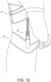
FIG. 9 is a rear view of the device with the user decompressed and resting on his or her side. -
FIG. 10 is a side view of an embodiment of the device. - The following detailed description is presented to enable any person skilled in the art to make and use the invention. For purposes of explanation, specific details are set forth to provide a thorough understanding of the present invention. However, it will be apparent to one skilled in the art that these specific details are not required to practice the invention. Descriptions of specific applications are provided only as representative examples. Various modifications to the preferred embodiments will be readily apparent to one skilled in the art, and the general principles defined herein may be applied to other embodiments and applications without departing from the scope of the invention as defined in the appended claims.
- This device solves the problems existing in the art by providing users a portable solution which they can operate while completing their normal daily activities. Unlike prior decompression devices which require users to remain in a single position without moving while receiving treatment from a second individual, this portable device can be operated and worn by users while driving, walking, working on a computer, sitting, cooking, etc. Furthermore, this invention provides pain relief to individuals with many different body shapes and sizes. For example, the device can be worn by children, athletes, and/or obese individuals who may be suffering the most from spinal disc pain.
- Referring to the drawings, as shown in
FIG. 1 , the device 9 consists ofadjustable belts traction tensioner assembly 30 with a plurality of traction devices at set anchor points to allow for elongation and decompression oftoothed rods 32 while on a user. - In the preferred embodiment of the device, the
thoracic belt 10 is designed to encircle the torso and serves as the host for the topvertical anchor points 13 for extension or decompression. Thelower lumbar belt 20 is designed to encircle the waist area and serves as the host for the lowervertical anchor points 23 for extension or decompression. Topvertical anchor points 13 and lowervertical anchor point 23 are attached or positioned into the topthoracic belt 10 andlower lumbar belt 20 respectively. - Both belts, the
thoracic belt 10 andlumbar belt 20 are adjustable such that they can accommodate people of larger girths. In a preferred embodiment, the belts are adjoined by hook and loops which allow the position of thedecompression rods 32 to be adjusted forward or back along the belts to accommodate a wide range of user sizes and body types and enhance the device's use as a treatment tool certain spinal disorders such as scoliosis. - The
belts - Also, the belts can be securely fastened and adjoined by mechanisms other than the hook and loop, such as clasps, buckles, snaps or any other type of adjoinment.
- The belts may also include molded pieces, padding or inserts for greater comfort, tighter fits or more precise movement and adjustments. However, the belt design is not required for the present invention, and any other mechanisms capable of securing the traction tensioner assembly to the user are contemplated by this invention.
- The decompression device operates by extending the distance between the two belts. Mechanisms for extending a
rod 32 or exerting pressure between top andbottom anchor points - However, in the preferred embodiment, the
traction tensioner assembly 30 serves as the connecting element betweenanchor points thoracic belt 10 and thelumbar belt 20 as well as the element to apply force utilized for extension or decompression. Thetraction tensioner assembly 30 allows the user to exert reasonable lift or force needed to decompress and then return to a neutral position by way of a user operated ratchet type actuator mechanism and incorporated release. When in use, the ratchet type actuator moves bi-directionally along thetoothed rods 32 when lift or force is exerted upon the actuator handles 35 by the user. - To assemble the preferred embodiment of the device, the
thoracic belt 10, containing at least twotop anchor points 13 is inserted with theupper end 31 of two traction tensioner assemblies, one assembly for each anchor point inserted to form 90 degree angles. Thelumbar belt 20, likewise containing at least twolower anchor points 23, is inserted with the lower portion of the same twotraction tensioner assemblies 34, thus holding the two traction tensioner assemblies 30 on each side of theadjustable belts - The user first attaches the upper
thoracic belt 10 around their chest, positioning close up in the axilla (armpit) area and adjusts saidbelt 10 for a tight fit using an elastic hook and loop closure of the thoracicinner wrap belt 11. Theouter tension adjustment 12 can further be cinched to ensure a snug custom fit. The twotop anchor points 13 attached to the belt on opposite halves are positioned snuggly within the recess of the axilla. - Next, the
bottom lumbar belt 20 is placed around the waist and adjusted for a tight fit using the elastic hook and loop closure of the lumbarinner wrap belt 21. The user will note that thetraction tensioner assembly 30 on each side runs from the axilla toward the hip and parallel to the body. As shown inFIGs. 1 and2 , once the user has finished attaching the device 9, it is compressed in neutral or start position. - To extend the
traction tensioner assembly 30 and begin decompression as shown inFIG. 7 , the user simply grasps the incorporatedactuator 33 with quick release handle 35 on the side of eachtraction tensioner assembly 30, raising and lowering the handles 35 in a back and forth ratchet action. An audible ratcheting sound confirms the extending action of the along thetoothed rods 32 caused by stroking thehandles 33. - As the
respective belts FIG. 4 , when the handles are upright or in a positive position, the device is ready for the user to stroke the handles 35 down to apply more tension. Alternatively, as shown inFIGs. 3 and10 , the handles 35 are placed in a down position when the user feels they have reached a point of relief or decompression. After reaching this point of relief, as shown inFIG. 8 , the users can continue their normal daily activities in in most any position such as standing, sitting, or laying. - Once the user feels relief or that they have sufficiently decompressed for one session, it is simply a matter of activating the quick release 35 on each
traction tensioner assembly 30actuator 33 to return the unit to a neutral position. Theadjustable belts - The anchor points 13, 23 which receive and transfer force for decompression can be fixed and utilized in various embodiments and of varying materials, including as illustrated in adjustable belts or in vests, single and dual point anchors which are transportable between utility style belts and various harnesses.
- As shown in
FIG. 9 , a potential embodiment of the device 9 includes usingrods 32 with telescoping stock to further reduce the height requirements of therod 32 lengths when in a neutral starting position and further increase the range of individual users able to use the device 9. - A potential embodiment of the device provides an audible indicator when extension or decompression is being initiated, engaged or proceeding, with or without electronic readout for certain indicators such as pounds of force, time duration or length of extension.
- The device can also be used to alleviate pain in different areas of the body. For instance, the device can be used to provide cervical traction to a user's neck.
- The terms "comprising," "including," and "having," as used in the claims and specification herein, shall be considered as indicating an open group that may include other elements not specified. The terms "a," "an," and the singular forms of words shall be taken to include the plural form of the same words, such that the terms mean that one or more of something is provided. The term "one" or "single" may be used to indicate that one and only one of something is intended. Similarly, other specific integer values, such as "two," may be used when a specific number of things is intended. The terms "preferably," "preferred," "prefer," "optionally," "may," and similar terms are used to indicate that an item, condition or step being referred to is an optional (not required) feature of the invention.
- The invention has been described with reference to various specific and preferred embodiments and techniques. However, it should be understood that many variations and modifications may be made while remaining within the scope of the invention defined by the appended claims.
- While the invention has been described with respect to a limited number of embodiments, those skilled in the art, having benefit of this disclosure, will appreciate that other embodiments can be devised which do not depart from the scope of the invention which is limited only by the attached claims.
Claims (3)
- A spinal decompression device (9) comprising:a. a thoracic belt (10) configured to wrap around a user's chest and be positioned in the user's axilla area, wherein the upper thoracic belt (10) is formed of a material having stretchable and fixed fibers configured to contour around the user's chest;b. a lumbar belt (20) configured to wrap around the user's waist, wherein the lumbar belt (20) is formed of a material having stretchable and fixed fibers configured to contour around the user's waist;c. top anchor points (13) positioned on the thoracic belt (10) and bottom anchor points (23) positioned on the lumbar belt (20);d. rods (32) extending between the top anchor points (13) and the bottom anchor points (23); ande. a traction tensioner assembly (30) capable of extending the rods (32) from a neutral position, wherein the traction assembly (30) comprises an user operated ratchet type actuator mechanism (33) with actuator handles with quick release mechanism (35);wherein the actuator mechanism (33) moves bi-directionally along the rods (32) when lift or force is exerted upon the actuator handles to facilitate spinal column decompression between the thoracic belt (10) and the lumbar belt (20); andwherein the actuator mechanism (33) is configured to be operable by a user wearing the spinal decompression device (9).
- The device of claim 1 wherein activating the quick release mechanism (35) returns the decompression device (9) to the neutral position.
- The device of claim 1 wherein the rods (32) are telescoping stock.
Applications Claiming Priority (2)
| Application Number | Priority Date | Filing Date | Title |
|---|---|---|---|
| US201562144958P | 2015-04-09 | 2015-04-09 | |
| PCT/US2016/026257 WO2016164490A1 (en) | 2015-04-09 | 2016-04-06 | Method and apparatus for spinal disc decompression |
Publications (4)
| Publication Number | Publication Date |
|---|---|
| EP3280366A1 EP3280366A1 (en) | 2018-02-14 |
| EP3280366A4 EP3280366A4 (en) | 2018-10-24 |
| EP3280366C0 EP3280366C0 (en) | 2023-08-30 |
| EP3280366B1 true EP3280366B1 (en) | 2023-08-30 |
Family
ID=57072906
Family Applications (1)
| Application Number | Title | Priority Date | Filing Date |
|---|---|---|---|
| EP16777219.3A Active EP3280366B1 (en) | 2015-04-09 | 2016-04-06 | Apparatus for spinal disc decompression |
Country Status (14)
| Country | Link |
|---|---|
| US (1) | US11931283B2 (en) |
| EP (1) | EP3280366B1 (en) |
| JP (1) | JP2018513763A (en) |
| KR (1) | KR20170135908A (en) |
| CN (1) | CN107613910A (en) |
| AU (2) | AU2016246601A1 (en) |
| CA (1) | CA2982113A1 (en) |
| EA (1) | EA201792171A1 (en) |
| ES (1) | ES2959615T3 (en) |
| HK (1) | HK1244420A1 (en) |
| HU (1) | HUE064208T2 (en) |
| MX (1) | MX2017012892A (en) |
| PL (1) | PL3280366T3 (en) |
| WO (1) | WO2016164490A1 (en) |
Families Citing this family (7)
| Publication number | Priority date | Publication date | Assignee | Title |
|---|---|---|---|---|
| US10045875B2 (en) * | 2016-05-03 | 2018-08-14 | Ekramul Haque | Vest to provide decompression and traction for spine and method of use |
| CA3023593A1 (en) | 2016-05-19 | 2017-11-23 | Auctus Surgical, Llc | Spinal curvature modulation systems |
| US11504259B2 (en) | 2016-12-05 | 2022-11-22 | University Of Tennessee Research Foundation | Controlled tension device fastening devices, systems, and methods |
| US11213419B2 (en) | 2017-04-05 | 2022-01-04 | University Of Tennessee Research Foundation | Distractive and mobility-enabling lumbar spinal orthosis devices, systems, and methods for treating mechanical low back pain |
| RU187499U1 (en) * | 2018-05-15 | 2019-03-11 | Дмитрий Александрович Ложкин | TRACTION Corset |
| RU189471U1 (en) * | 2019-01-09 | 2019-05-23 | Сайд-Эмин Баудинович Дадаев | Corset for stretching the spine |
| JP7423211B2 (en) * | 2019-07-18 | 2024-01-29 | ユーピーアール株式会社 | Movement support device |
Citations (1)
| Publication number | Priority date | Publication date | Assignee | Title |
|---|---|---|---|---|
| US2835247A (en) * | 1956-08-28 | 1958-05-20 | Ludwik M Stabholc | Lumbar traction apparatus |
Family Cites Families (25)
| Publication number | Priority date | Publication date | Assignee | Title |
|---|---|---|---|---|
| US2642306A (en) * | 1951-03-16 | 1953-06-16 | William R Beeler | Scrap paper spear |
| IL41411A (en) * | 1973-01-29 | 1976-05-31 | Stabholy L | Lumbar traction apparatus |
| US3889664A (en) | 1974-05-13 | 1975-06-17 | Gordon D Heuser | Ambulatory traction treatment apparatus |
| NZ214557A (en) * | 1984-12-18 | 1989-07-27 | Yulorwoh Pty Ltd | Traction device: biasing means includes slide members and springs |
| US4715362A (en) * | 1986-02-27 | 1987-12-29 | Henry Scott | Ambulatory lumbo-sacral traction systems and methods |
| IL84695A0 (en) * | 1987-12-02 | 1988-06-30 | Ludwig Shtabholz | Lumbar traction apparatus |
| CN2038378U (en) | 1988-09-22 | 1989-05-31 | 施仁照 | Portable lumbar vertebra tractor |
| CN2053093U (en) | 1989-07-06 | 1990-02-21 | 施仁照 | Portable tractor for lumbar vertebra |
| NO180514C (en) * | 1995-01-18 | 1997-05-07 | Svein Ousdal | Device for stretch corsets and neck straps |
| US5651764A (en) * | 1996-03-05 | 1997-07-29 | Chiu; Shui-Shang | Portable apparatus for reforming spine |
| US6280405B1 (en) | 1996-12-03 | 2001-08-28 | Fisheries Management And Supply Co A.B. | Device for stationary and/or ambulant traction of the spinal column |
| CN2351111Y (en) | 1998-08-19 | 1999-12-01 | 吴智江 | Lumbar vertebra tractor |
| US6533740B2 (en) * | 2001-03-01 | 2003-03-18 | Amei Technologies Inc. | Lifting mechanism for a traction device |
| US7144380B2 (en) | 2001-07-23 | 2006-12-05 | Gilliam Larry A | Traction method and device |
| US20040073150A1 (en) * | 2002-10-15 | 2004-04-15 | Roballey Thomas C. | Ambulatory trans-lumbar traction system |
| US7276038B2 (en) * | 2003-01-14 | 2007-10-02 | Amei Technologies Inc. | Field adjustable traction device |
| KR100612432B1 (en) | 2003-07-26 | 2006-08-16 | 빈 이 | Pneumatic Lumbar Traction device |
| CN2676868Y (en) | 2003-12-28 | 2005-02-09 | 徐安顺 | Lumbar vertebra traction therapeutic instrument |
| US20060161083A1 (en) | 2005-01-15 | 2006-07-20 | Dunfee Matthew J | Ambulatory spinal unloading method and apparatus |
| CN200939192Y (en) | 2006-08-24 | 2007-08-29 | 贺石生 | Lambar tractor |
| CN201026255Y (en) | 2006-10-30 | 2008-02-27 | 徐安顺 | Traction instrument for lumbar |
| CN201524158U (en) | 2009-08-26 | 2010-07-14 | 张克俭 | Lumbar traction instrument capable of adjusting bidirectionally |
| KR101138911B1 (en) | 2011-04-08 | 2012-07-12 | 유인섭 | Belt for the lumber tow |
| KR101370518B1 (en) | 2012-07-27 | 2014-03-10 | 유인섭 | belt |
| US9308036B2 (en) | 2013-01-27 | 2016-04-12 | Ivan L. Robinson | Portable assembly and method for treating desiccated and injured spinal discs |
-
2016
- 2016-04-06 ES ES16777219T patent/ES2959615T3/en active Active
- 2016-04-06 US US15/092,545 patent/US11931283B2/en active Active
- 2016-04-06 CA CA2982113A patent/CA2982113A1/en active Pending
- 2016-04-06 EP EP16777219.3A patent/EP3280366B1/en active Active
- 2016-04-06 MX MX2017012892A patent/MX2017012892A/en unknown
- 2016-04-06 CN CN201680026848.9A patent/CN107613910A/en active Pending
- 2016-04-06 HU HUE16777219A patent/HUE064208T2/en unknown
- 2016-04-06 JP JP2018503734A patent/JP2018513763A/en active Pending
- 2016-04-06 WO PCT/US2016/026257 patent/WO2016164490A1/en active Application Filing
- 2016-04-06 PL PL16777219.3T patent/PL3280366T3/en unknown
- 2016-04-06 AU AU2016246601A patent/AU2016246601A1/en not_active Abandoned
- 2016-04-06 KR KR1020177032000A patent/KR20170135908A/en active IP Right Grant
- 2016-04-06 EA EA201792171A patent/EA201792171A1/en unknown
-
2018
- 2018-03-06 HK HK18103152.8A patent/HK1244420A1/en unknown
-
2020
- 2020-11-25 AU AU2020277156A patent/AU2020277156A1/en not_active Abandoned
Patent Citations (1)
| Publication number | Priority date | Publication date | Assignee | Title |
|---|---|---|---|---|
| US2835247A (en) * | 1956-08-28 | 1958-05-20 | Ludwik M Stabholc | Lumbar traction apparatus |
Also Published As
| Publication number | Publication date |
|---|---|
| ES2959615T3 (en) | 2024-02-27 |
| HK1244420A1 (en) | 2018-08-10 |
| EP3280366C0 (en) | 2023-08-30 |
| PL3280366T3 (en) | 2024-02-12 |
| JP2018513763A (en) | 2018-05-31 |
| US11931283B2 (en) | 2024-03-19 |
| CN107613910A (en) | 2018-01-19 |
| US20160296361A1 (en) | 2016-10-13 |
| CA2982113A1 (en) | 2016-10-13 |
| WO2016164490A1 (en) | 2016-10-13 |
| KR20170135908A (en) | 2017-12-08 |
| MX2017012892A (en) | 2018-05-02 |
| AU2020277156A1 (en) | 2020-12-24 |
| HUE064208T2 (en) | 2024-02-28 |
| EP3280366A1 (en) | 2018-02-14 |
| EA201792171A1 (en) | 2018-07-31 |
| AU2016246601A1 (en) | 2017-11-02 |
| EP3280366A4 (en) | 2018-10-24 |
| NZ736236A (en) | 2023-08-25 |
Similar Documents
| Publication | Publication Date | Title |
|---|---|---|
| EP3280366B1 (en) | Apparatus for spinal disc decompression | |
| US20210113359A1 (en) | Spinal orthosis | |
| AU699290B2 (en) | Inflatable spinal traction device | |
| CA2073069A1 (en) | Portable traction apparatus | |
| US20130023931A1 (en) | Spinal traction device | |
| US20030130696A1 (en) | Method and portable apparatus for spinal adjustment | |
| KR20030032790A (en) | A chair for rectifing the spine | |
| US5637079A (en) | Traction apparatus | |
| WO2015019351A2 (en) | Novik mehanurgichesky table or portable traction apparatus for manual therapy and massage | |
| NZ736236B2 (en) | Method and apparatus for spinal disc decompression | |
| US7041071B2 (en) | Method and apparatus for adjusting lumbosacral area | |
| CN209847494U (en) | Waist two-side adjustable elastic support type waist support device | |
| CN106726067B (en) | Multifunctional suspension type vertebra traction rehabilitation therapeutic machine | |
| HU229977B1 (en) | Apparatus for regenerating spine | |
| JP3229852B2 (en) | Device for treatment or prevention of back pain | |
| CN203524828U (en) | Cervical vertebra tractor | |
| EA040979B1 (en) | METHOD AND DEVICE FOR DECOMPRESSION OF VERTEBRAL DISC | |
| CN203506948U (en) | Cervical vertebra and lumbar vertebra tractor | |
| KR200293741Y1 (en) | Portable automatic traction apparatus | |
| RU214872U1 (en) | A device for stretching the spine due to gravity under the weight of a person's own body | |
| JP6042755B2 (en) | Simple freestanding traction tool | |
| WO2003051159A1 (en) | Chair for spinal therapy | |
| JP3178018U (en) | Back pain relief supporter | |
| KR20220041967A (en) | Chair type orthodontic treatment device with spinal traction alignment function | |
| KR20190081419A (en) | Joint mobilization Device having Cuff-shape |
Legal Events
| Date | Code | Title | Description |
|---|---|---|---|
| STAA | Information on the status of an ep patent application or granted ep patent |
Free format text: STATUS: THE INTERNATIONAL PUBLICATION HAS BEEN MADE |
|
| PUAI | Public reference made under article 153(3) epc to a published international application that has entered the european phase |
Free format text: ORIGINAL CODE: 0009012 |
|
| STAA | Information on the status of an ep patent application or granted ep patent |
Free format text: STATUS: REQUEST FOR EXAMINATION WAS MADE |
|
| 17P | Request for examination filed |
Effective date: 20171009 |
|
| AK | Designated contracting states |
Kind code of ref document: A1 Designated state(s): AL AT BE BG CH CY CZ DE DK EE ES FI FR GB GR HR HU IE IS IT LI LT LU LV MC MK MT NL NO PL PT RO RS SE SI SK SM TR |
|
| AX | Request for extension of the european patent |
Extension state: BA ME |
|
| DAV | Request for validation of the european patent (deleted) | ||
| DAX | Request for extension of the european patent (deleted) | ||
| REG | Reference to a national code |
Ref country code: HK Ref legal event code: DE Ref document number: 1244420 Country of ref document: HK |
|
| A4 | Supplementary search report drawn up and despatched |
Effective date: 20180924 |
|
| RIC1 | Information provided on ipc code assigned before grant |
Ipc: A61F 5/02 20060101AFI20180918BHEP Ipc: A61F 5/04 20060101ALI20180918BHEP Ipc: A61F 5/048 20060101ALI20180918BHEP Ipc: A61F 5/03 20060101ALI20180918BHEP |
|
| STAA | Information on the status of an ep patent application or granted ep patent |
Free format text: STATUS: EXAMINATION IS IN PROGRESS |
|
| 17Q | First examination report despatched |
Effective date: 20191120 |
|
| STAA | Information on the status of an ep patent application or granted ep patent |
Free format text: STATUS: EXAMINATION IS IN PROGRESS |
|
| STAA | Information on the status of an ep patent application or granted ep patent |
Free format text: STATUS: EXAMINATION IS IN PROGRESS |
|
| GRAP | Despatch of communication of intention to grant a patent |
Free format text: ORIGINAL CODE: EPIDOSNIGR1 |
|
| STAA | Information on the status of an ep patent application or granted ep patent |
Free format text: STATUS: GRANT OF PATENT IS INTENDED |
|
| INTG | Intention to grant announced |
Effective date: 20230323 |
|
| GRAS | Grant fee paid |
Free format text: ORIGINAL CODE: EPIDOSNIGR3 |
|
| GRAA | (expected) grant |
Free format text: ORIGINAL CODE: 0009210 |
|
| STAA | Information on the status of an ep patent application or granted ep patent |
Free format text: STATUS: THE PATENT HAS BEEN GRANTED |
|
| AK | Designated contracting states |
Kind code of ref document: B1 Designated state(s): AL AT BE BG CH CY CZ DE DK EE ES FI FR GB GR HR HU IE IS IT LI LT LU LV MC MK MT NL NO PL PT RO RS SE SI SK SM TR |
|
| REG | Reference to a national code |
Ref country code: GB Ref legal event code: FG4D |
|
| REG | Reference to a national code |
Ref country code: CH Ref legal event code: EP |
|
| REG | Reference to a national code |
Ref country code: DE Ref legal event code: R096 Ref document number: 602016082326 Country of ref document: DE |
|
| REG | Reference to a national code |
Ref country code: IE Ref legal event code: FG4D |
|
| U01 | Request for unitary effect filed |
Effective date: 20230925 |
|
| U07 | Unitary effect registered |
Designated state(s): AT BE BG DE DK EE FI FR IT LT LU LV MT NL PT SE SI Effective date: 20230928 |
|
| REG | Reference to a national code |
Ref country code: NO Ref legal event code: T2 Effective date: 20230830 |
|
| PG25 | Lapsed in a contracting state [announced via postgrant information from national office to epo] |
Ref country code: GR Free format text: LAPSE BECAUSE OF FAILURE TO SUBMIT A TRANSLATION OF THE DESCRIPTION OR TO PAY THE FEE WITHIN THE PRESCRIBED TIME-LIMIT Effective date: 20231201 |
|
| PG25 | Lapsed in a contracting state [announced via postgrant information from national office to epo] |
Ref country code: IS Free format text: LAPSE BECAUSE OF FAILURE TO SUBMIT A TRANSLATION OF THE DESCRIPTION OR TO PAY THE FEE WITHIN THE PRESCRIBED TIME-LIMIT Effective date: 20231230 |
|
| PG25 | Lapsed in a contracting state [announced via postgrant information from national office to epo] |
Ref country code: RS Free format text: LAPSE BECAUSE OF FAILURE TO SUBMIT A TRANSLATION OF THE DESCRIPTION OR TO PAY THE FEE WITHIN THE PRESCRIBED TIME-LIMIT Effective date: 20230830 Ref country code: IS Free format text: LAPSE BECAUSE OF FAILURE TO SUBMIT A TRANSLATION OF THE DESCRIPTION OR TO PAY THE FEE WITHIN THE PRESCRIBED TIME-LIMIT Effective date: 20231230 Ref country code: HR Free format text: LAPSE BECAUSE OF FAILURE TO SUBMIT A TRANSLATION OF THE DESCRIPTION OR TO PAY THE FEE WITHIN THE PRESCRIBED TIME-LIMIT Effective date: 20230830 Ref country code: GR Free format text: LAPSE BECAUSE OF FAILURE TO SUBMIT A TRANSLATION OF THE DESCRIPTION OR TO PAY THE FEE WITHIN THE PRESCRIBED TIME-LIMIT Effective date: 20231201 |
|
| REG | Reference to a national code |
Ref country code: ES Ref legal event code: FG2A Ref document number: 2959615 Country of ref document: ES Kind code of ref document: T3 Effective date: 20240227 |
|
| REG | Reference to a national code |
Ref country code: HU Ref legal event code: AG4A Ref document number: E064208 Country of ref document: HU |
|
| PG25 | Lapsed in a contracting state [announced via postgrant information from national office to epo] |
Ref country code: SM Free format text: LAPSE BECAUSE OF FAILURE TO SUBMIT A TRANSLATION OF THE DESCRIPTION OR TO PAY THE FEE WITHIN THE PRESCRIBED TIME-LIMIT Effective date: 20230830 Ref country code: RO Free format text: LAPSE BECAUSE OF FAILURE TO SUBMIT A TRANSLATION OF THE DESCRIPTION OR TO PAY THE FEE WITHIN THE PRESCRIBED TIME-LIMIT Effective date: 20230830 Ref country code: CZ Free format text: LAPSE BECAUSE OF FAILURE TO SUBMIT A TRANSLATION OF THE DESCRIPTION OR TO PAY THE FEE WITHIN THE PRESCRIBED TIME-LIMIT Effective date: 20230830 Ref country code: SK Free format text: LAPSE BECAUSE OF FAILURE TO SUBMIT A TRANSLATION OF THE DESCRIPTION OR TO PAY THE FEE WITHIN THE PRESCRIBED TIME-LIMIT Effective date: 20230830 |