EP3270362B1 - Fire alarm with a measurement chamber and a switch holder for joint assembly of a fire sensor of the measuring chamber and at least one further sensor for detecting a measured variable in the environment outside the fire detector - Google Patents
Fire alarm with a measurement chamber and a switch holder for joint assembly of a fire sensor of the measuring chamber and at least one further sensor for detecting a measured variable in the environment outside the fire detector Download PDFInfo
- Publication number
- EP3270362B1 EP3270362B1 EP17155080.9A EP17155080A EP3270362B1 EP 3270362 B1 EP3270362 B1 EP 3270362B1 EP 17155080 A EP17155080 A EP 17155080A EP 3270362 B1 EP3270362 B1 EP 3270362B1
- Authority
- EP
- European Patent Office
- Prior art keywords
- fire
- light
- fire alarm
- sensor
- detector
- Prior art date
- Legal status (The legal status is an assumption and is not a legal conclusion. Google has not performed a legal analysis and makes no representation as to the accuracy of the status listed.)
- Revoked
Links
Images
Classifications
-
- G—PHYSICS
- G08—SIGNALLING
- G08B—SIGNALLING OR CALLING SYSTEMS; ORDER TELEGRAPHS; ALARM SYSTEMS
- G08B17/00—Fire alarms; Alarms responsive to explosion
- G08B17/10—Actuation by presence of smoke or gases, e.g. automatic alarm devices for analysing flowing fluid materials by the use of optical means
- G08B17/103—Actuation by presence of smoke or gases, e.g. automatic alarm devices for analysing flowing fluid materials by the use of optical means using a light emitting and receiving device
- G08B17/107—Actuation by presence of smoke or gases, e.g. automatic alarm devices for analysing flowing fluid materials by the use of optical means using a light emitting and receiving device for detecting light-scattering due to smoke
Definitions
- the invention relates to a fire detector which has a circuit carrier and a measuring chamber communicating with the ambient air.
- the measuring chamber comprises a fire sensor for detecting a fire characteristic. It is also housed in a detector housing of the fire detector.
- the measuring chamber comprises a base body as well as an opposing attachment body with a measuring space formed therebetween.
- the main body is designed for attachment to a mounting surface, in particular on a detector base.
- the measuring chamber can also be referred to as a detection unit.
- the base body and the Aufsetzêtharm are typically assembled during assembly.
- an optical smoke detector in which at least one planar-optical element is arranged in the beam path between the radiation source and the radiation receiver.
- This element can be either a diffractive element, preferably a holographic-optical element (HOE), or a microfine reflector (MFR).
- HOE holographic-optical element
- MFR microfine reflector
- the smoke detector comprises a sensor system for detecting an adjacent object, ultrasound signals can be transmitted and received by means of the sensor system, and a received ultrasound signal can be evaluated to detect an object.
- the sensor system comprises a plurality of ultrasound transmitters, which are aligned in such a way that they are in operation in the direction of a mounting surface, on which the smoke detector is mounted, radiate.
- the monitoring circuit of the smoke detector has as a receiver a microphone in the ultrasonic range, which is oriented in a direction away from the mounting surface, typically towards the ground.
- the microphone may be, for example, an electret microphone or a microphone in silicon technology (semiconductor technology), which is substantially smaller than a piezoelectric transducer.
- the microphone can be so small that it can be placed unobtrusively under the hood of the smoke detector.
- a scattered light smoke detector which has a communicating with the ambient air optical measuring chamber.
- the latter is accommodated inside a detector housing and limited by a main body and a detector hood of the detector housing.
- a preferably planar circuit carrier is added in the main body.
- a light emitting diode and a photosensor are arranged in a scattered light arrangement adjacent to the measuring chamber.
- the light-emitting diode and the photosensor each have an optical axis extending at least approximately orthogonally to the circuit carrier and lie opposite an inner side of the detector hood which delimits the measuring chamber.
- a part of the inside has a mirror surface, which is opposite to the light emitting diode.
- the mirror surface has a mirror geometry such that a light cone of the light-emitting diode intersects a reception region of the photosensor in a first scattered light volume within the measurement chamber.
- Fire detectors are well known. Like the fire detector according to the invention, they can be designed for connection to a detector bus or to a detector line. If a fire characteristic is detected, an alarm or warning message is output to the detector bus. Both messages can alternatively or additionally via radio and / or on Fire alarms are issued visually and / or acoustically.
- the considered fire detectors designed as point detectors can alternatively or additionally be designed for battery-supported stand-alone operation.
- the documents EP0399 244 and FR2 964 743 show scattered light smoke detector, which have a circuit carrier, the front side of the scattered light chamber faces and on the back of which electronic components are arranged. On this basis, it is an object of the invention to provide a particularly compact fire detector.
- the circuit carrier bears against the mounting body with an inner side facing the measuring space.
- the circuit carrier is provided for arranging the fire sensor and the at least one further sensor and / or the indicator LED.
- the core of the invention lies in the double use of the circuit carrier with the sensors applied there.
- the part of the sensors ie the fire sensor, part of the adjacent measuring chamber and sensor aligned to the measuring chamber.
- the other part of the sensors ie the at least one further sensor, is directed away from the measuring chamber into the adjacent surroundings of the fire detector.
- Another advantage is that the direct mounting of the sensors on the circuit carrier drastically reduces the EMC influence on the sensors. This is the case in particular for sensors which are designed as SMD components for direct surface mounting on the circuit carrier. Here elaborate shielding measures can be omitted.
- the indicator LED is provided to cyclically output a light pulse to indicate proper operational readiness and / or to indicate the presence of a fire alarm, such as a fire alarm. by faster flashing.
- the measuring chamber communicating with the ambient air may be an optical measuring chamber, such as a so-called labyrinth.
- a measuring chamber is permeable to the passage of smoke particles to be detected and to be detected combustion gases, such as carbon monoxide.
- the measuring chamber is shielded from direct ambient light.
- the optical measuring chamber can be based on the scattered light principle or on the extinction principle.
- the fire sensor has a light-emitting diode and a photosensor as part of the optical measuring chamber.
- the measuring chamber may have one or more gas sensors as a fire sensor for detecting flammable flue gases typical of fire.
- a fire detector is also referred to as a flue gas detector.
- the gas sensor such as a so-called GasFET, protrudes into the measuring chamber of the measuring chamber.
- the fire sensor is the main sensor of the fire detector.
- the detector housing comprises a base housing and a detector hood with at least one inlet opening formed therebetween.
- the latter is intended for the passage of combustion gases and smoke particles into the measuring chamber of the fire detector.
- the entrance opening may be slit-shaped, e.g. with a slit width in the range of 2 to 5 mm.
- the detector hood has a hood outer side facing away from the fire detector, and an opposite hood inside.
- the circuit board is located on the hood inside.
- the circuit carrier with a maximum distance A of 1.5 cm from the hood inner side spaced.
- the at least one further sensor and / or the indicator LED is opposite an opening in the detector hood or protrudes into this opening or protrudes through this opening.
- the (central) opening is located at a central position of the fire detector, in particular at a vertex of the detector hood.
- the opening may be a recess. It preferably has a circular diameter. The diameter is in particular in a range of 1 to 30 mm, preferably in a range of 3 to 15 mm.
- the main body and the detector hood can both be in one piece. They are both preferably plastic injection molding parts.
- the circuit carrier accommodated in the detector hood is preferably a planar printed circuit board.
- the fire detector has a control unit arranged on the control unit, preferably a microcontroller.
- the control unit is each signal or data technology with the fire sensor for detecting a fire characteristic and with the at least one sensor for detecting the respective measured variable and / or connected to the indicator LED for optical output of the operating display.
- the control unit has an interface and is adapted to detect by the interface a respective sensor information and / or output by the interface a respective alarm message in an impermissible deviation from a respective detected sensor measured value.
- the control unit may be configured to bundle the respective alarm messages and output them as an alarm message. It can also be set up to evaluate and / or weight the respective alarm messages in the sense of a multi-criteria alarm in combination. It can finally be set up to use the further sensor signals for testing the fire sensor signal for plausibility. This reduces the output of a false alarm.
- the at least one sensor is a temperature sensor and in particular a thermistor for detecting a temperature in the immediate vicinity of the fire detector.
- the thermistor is a so-called NTC (for negative temperature coefficient thermistor).
- the control unit is set up, when a temperature value detected by the temperature sensor, such as a temperature value is exceeded. of 60 °, and / or when exceeding a temperature gradient, e.g. of 5 ° / min, to output a temperature information or alarm message.
- the at least one further sensor may be a light receiver, such as a photodiode.
- the light receiver is provided for detecting an ambient brightness.
- the control unit is set up to suppress the output of an optical and / or acoustic warning message at night when a brightness value, for example 10 lux detected by the photosensor, drops below the output of an optical and / or acoustic warning message, if a battery is to supply energy of the fire detector falls below a voltage value for a low state of charge.
- the at least one further sensor may be a gas sensor for detecting a flue gas concentration, in particular carbon monoxide.
- the gas sensor is e.g. a semiconductor gas sensor, and preferably a so-called gas FET.
- the control unit is adapted to operate when a minimum gas concentration such as e.g. of 300 ppm carbon monoxide, a gas information and / or an alarm message.
- the at least one further sensor may be a thermal radiation sensor for detecting open fire or blazing embers in the vicinity of the fire detector, in particular a thermopile (thermopile) or a bolometer.
- the control unit is adapted to detect a characteristic flicker frequency, e.g. in the range of 8 to 20 Hz in the sensor signal of the heat radiation sensor to output a flame information and / or an alarm message.
- the thermal radiation sensor may also include a PIR sensor (for Passive InfraRed) for detecting movements such as motion. of people to be in the vicinity of the fire alarm. In this case, the control unit is set up to output movement information or an alarm message upon detected movement of objects.
- the at least one further sensor may be a microphone for receiving ultrasonic waves from the surroundings of the band detector.
- the control unit is set up to evaluate a microphone signal output by the microphone in terms of time, for example with respect to temporal reference to ultrasonic waves, which are preferably emitted cyclically by the fire detector and which are reflected by objects in the vicinity of the fire detector.
- a fault message can then be output if a detected object is within a predetermined distance from the fire detector.
- the fault message only then is output if the microphone signal exceeds a minimum level, so that smaller microphone levels of typically smaller and negligible objects can be disregarded.
- the microphone may alternatively or additionally be provided and designed to receive noises from the environment of the fire detector.
- the control device may in this case be adapted to output a noise information or an alarm message when a microphone detected noise level exceeds a minimum level.
- the detector hood has a (continuous) opening in a vertex of the detector hood.
- the outside of the circuit substrate is opposite to the opening.
- the vertex is preferably located on an axis of symmetry, in particular on a rotational symmetry axis or constructive main axis of the fire detector.
- fire detectors have an approximately rotationally symmetrical design. From this central point, a uniform "all-round view" around the fire detector is advantageously possible. At the same time, an advantageously direction-independent temperature detection by means of the temperature sensor is possible at this central point.
- the opening in the detector hood is provided with a cover which is transparent to electromagnetic radiation in the wavelength range from 400 nm to 25 ⁇ m.
- the transparent cover may be made of a plastic or of glass. It can completely close the opening.
- the transparent cover may have one or more passage openings to allow passage of ambient air for temperature detection or fire gas detection to the at least one sensor.
- the transparent cover may also form an optical lens for expanding the optical detection area. This is open fire, blazing embers or movements of larger objects, such as For example, by humans, advantageously detectable in a larger environment of the fire alarm.
- At least the heat radiation sensor is arranged on the circuit carrier.
- the opening in the detector hood is provided with a cover which is transparent only for medium infrared radiation in the wavelength range from 2 to 25 ⁇ m.
- the cover appears in the optically visible region of a human being as opaque, in particular as opaque.
- the transparent cover may for example be made of a plastic, in which scattering particles are introduced.
- the plastic may alternatively have a structuring which scatters visible light and allows medium infrared radiation to pass to the major part.
- visible light is meant the human optically perceptible wavelength range of about 380 nm to 780 nm.
- Suitable materials for the cover are eg from the EP 2 715 792 A1 known.
- the fire sensor comprises a light-emitting diode and a photosensor (6).
- the light emitting diode and the photosensor are arranged in a scattered light arrangement for optical smoke detection according to the scattered light principle.
- the light-emitting diode and the photosensor are arranged opposite each other for optical smoke detection according to the extinction principle.
- the measuring volume for the transmitted light measurement is in the measuring chamber of the measuring chamber.
- the light-emitting diode can be a single-color light-emitting diode which emits monochromatic light, for example in the wavelength range from 380 to 1000 nm. It can be a two-color light-emitting diode which is designed to generate a first light beam or a first light cone in a first wavelength range from 380 to 540 nm and / or a second light beam or a second light cone in a second wavelength range from 750 to 1000 nm for smoke detection according to the two-color principle send out. Due to the color-specific evaluation of the photosensor signal, a fire technical analysis of the detected smoke particles with regard to their particle size and thus a determination of the type of smoke is possible.
- the light emitting diode and the photosensor are optically aligned to a common scattered light volume within the measuring space.
- the photosensor is arranged on the circuit carrier in such a way that a main axis or axis of symmetry extending through the center of the fire detector extends both through the scattered light volume and through the photosensor.
- the light-emitting diode and the photosensor are arranged and aligned on the circuit carrier such that they each have an optical axis extending at least approximately orthogonally to the circuit carrier.
- a part of the inside of the main body has a mirror surface, which is opposite to the light emitting diode.
- the mirror surface has a mirror geometry such that a light cone of the light-emitting diode intersects a receiving region of the photosensor in a scattered light volume within the measuring chamber of the measuring chamber.
- the mirror surface may e.g. have a spherical geometry, which causes a bundling of the incident light beam.
- the mirror surface may be part of the surface e.g. a ball, an ellipsoid or a paraboloid.
- the mirror surface may have a plane or a concave surface. It may be a silvery foil or a sheet metal piece, such as aluminum or steel. The film can be glued on the inside of the body. The sheet metal piece can be glued to this inside, for example, or attached during injection molding of the body.
- the mirror surface may also be a metallized surface which For example, by means of a vapor deposition in vacuum is applied.
- the mirror surface may also be a plastic mirror with a shiny or polished surface, such as black plastic.
- the attachment body preferably has or forms at least one diaphragm for the light-emitting diode and for the photosensor, the light trap and / or light-absorbing structures as integral parts of the attachment body.
- the attachment body is preferably a black plastic injection molded part. He can be independently provided with a black paint job.
- the mounting body covers substantially all of the measuring space of the measuring chamber facing the inside of the circuit substrate except for the aforementioned recesses.
- the circuit carrier is thus as in a sandwich between the Aufsetzêtraj and the detector hood. This advantageously allows a particularly compact design and easy integration of the other sensors and the indicator LED on the circuit board. The latter is advantageously adjacent directly to the detector hood and thus also to the environment to be monitored outside the fire alarm.
- the detector hood may, for example, have a spherical, arched design or the shape of a cylindrical lid with a circular flat bottom. It is usually made of a white plastic.
- a part of the inside of the base body has a focusing element, which is opposite to the photosensor and which has such a focus geometry that scattered light is reflected from the scattered light volume in the direction of the photosensor.
- the focusing element is arranged such that the constructive main axis or the rotational axis of symmetry of the fire detector extends through the (geometric) center of the focusing element and through the scattered light volume and is aligned with the optical receiving axis of the photosensor. Due to the additionally incident on the photosensor scattered light, the sensitivity of the photosensor is advantageously increased.
- the focusing element has according to a further embodiment of the invention, a plurality of optically reflective and adjacent segments.
- Each segment is part of an ellipsoid, in particular an ellipsoid of revolution, whose first focal point lies in the scattered light volume and whose second focal point lies directly in front of the photosensor.
- intermediate is meant that the second focus is at a distance of not more than 5 mm in front of the photosensitive sensor layer of the photosensor.
- the segmented design of the focusing element results in a low overall height of the focusing element. As a result, the focusing element protrudes less into the measuring chamber of the measuring chamber and thus advantageously forms a smaller flow obstacle against penetrating smoke.
- the focusing element is preferably designed as a "black” mirror. In particular, it is a shiny part of an injection molded part made of black plastic of the main body.
- the mirror surface opposite the light-emitting diode has a mirror geometry such that the light cone of the light-emitting diode traverses the measuring space and opens into a light-absorbing light trap.
- the light trap is preferably pot-shaped or funnel-shaped. In particular with respect to the main incident direction of the light rays reflected by the mirror surface, it has geometrically oriented surfaces and / or corrugations such that the light rays incident thereon cancel out or "run dead" after a number of reflections.
- the light trap is shaped in the form of a funnel in the base body.
- the funnel extends in a radial outer region of the base body substantially coaxially about a main axis extending through the center of the fire detector.
- the funnel shape advantageously enables even more effective light absorption by a large number of reflections within the funnel.
- Another advantage lies in the structurally simple spatial integration of the funnel in the radial outer region of the body.
- a plurality of ultrasound transmitters are arranged on the circuit carrier. They are aligned so that they radiate in operation towards a mounting surface on which the fire detector is mounted.
- a plurality of ultrasonic receivers or a plurality of ultrasonic transceivers are each arranged as a structural unit of an ultrasonic transmitter and an ultrasonic receiver.
- the ultrasonic receivers are oriented towards the mounting surface to to detect ultrasonic waves during operation from this direction.
- at least one microphone as a further sensor of the fire detector is arranged on the circuit carrier such that it lies opposite the opening in the detector hood, protrudes into this opening or protrudes through this opening.
- the opening is preferably arranged at the apex of the detector hood.
- the control unit is set up to control the respective ultrasound transmitters for emitting an acoustic signal in the direction of the mounting surface, to evaluate in time a respective ultrasound signal originating from the ultrasound receivers or from the microphone and reflected from objects in the surroundings of the fire detector and to output a fault message if within a predetermined distance around the fire detector, such as at a distance of 50 cm around the fire detector, a detected object is located.
- the fault message can be output if, in addition, the ultrasound signal received by the microphone exceeds a minimum level.
- the mounting surface is typically the ceiling in a building. It can alternatively be a wall.
- the mounting surface may also be a mounting base on which the fire detector is in particular releasably attachable and which in turn is attached to the ceiling or on the wall.
- the mounting base is in particular plate-shaped and preferably circular.
- the mounting base may extend radially outward to the extent that hits an ultrasonic signal or ultrasound beam emitted by the respective ultrasound transmitter or ultrasound transceiver onto the mounting base.
- the fire detector has at least one preferably formed in the base body reflection surface in the beam path from the respective ultrasonic transmitter to the mounting surface.
- the reflection surfaces may be formed such that they have bundling properties for the emitted ultrasonic waves.
- the reflection surfaces are concave.
- the particular advantage is that the ultrasound transmitter, ultrasound receiver and, as a combination thereof, ultrasound transceivers can be flatly applied to the circuit carrier.
- the beam steering takes place through the reflection surfaces.
- the abovementioned ultrasound units are arranged on the inside of the circuit carrier facing the interior of the fire detector, and preferably on the radial outer edge of the circuit carrier.
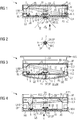
- FIG. 1 shows a first embodiment of a fire detector 1 according to the invention with a plurality of other sensors 6 ', 7, 8, TS, MIC and with an indicator LED LED in the region of a central opening OP in a detector hood 4 of the fire detector 1.
- the fire detector shown. 1 has a measuring chamber M communicating with the ambient air for detecting a fire characteristic by means of a fire sensor 5, 6.
- a fire characteristic may be, for example, a smoke particle concentration, a fire gas concentration, such as CO concentration, or an excess temperature.
- the measuring chamber M is in the present example, an optical measuring chamber M, which is also referred to as a labyrinth. It forms a measuring space IR together with a main body G and an attachment body A.
- the main body G has a connection side AN for attaching the fire detector 1 to a mounting surface, such as on a ceiling or wall on.
- a connection side AN for attaching the fire detector 1 to a mounting surface, such as on a ceiling or wall on.
- On the connection side are ON arranged two contacts K, which are connected to the circuit substrate 9 signal or data technology.
- the contacts K are provided for contacting the fire detector 1 to a detector line. You contact after attachment of the fire detector 1 to a detector base there correspondingly trained mating contacts.
- the connecting lines between the contacts K and the circuit carrier 9 preferably extend outside the measuring space IR. With MA the outside of the detector hood 4 is designated.
- the detector hood 4 is a cylindrical cover D in the example shown.
- a circuit carrier 9 is arranged in the detector hood 4 with an inner side LI facing the measuring space IR and an outer side LA opposite this.
- the outside LA of the circuit substrate 9 is located directly on an inner side MI of the detector hood 4.
- a temperature sensor TS are arranged, in particular an NTC, another photosensor 6 'for measuring the ambient brightness, a gas sensor 7, e.g. a GasFET for CO measurement, a heat radiation sensor 8, in particular a thermopile, arranged for flame and motion detection, a microphone MIC and an indicator LED LED for visual operational readiness indication in the environment.
- the aforementioned components TS, 6 ', 7, 8, MIC, LED are arranged on the circuit carrier 9, that they oppose the opening OP.
- the opening OP has a diameter in the range of 5 to 10 mm and a depth of about 2 mm.
- the opening OP is arranged in a vertex SP of the detector hood 4, ie centrally or centrally in the detector hood 4. It is thus the outside LA of the circuit substrate 9 of the opening OP directly opposite.
- central or “central” is meant that the major structural axis or axis of symmetry SA of the fire detector 1 passes through the opening OP.
- the opening OP is provided with a cover AB, which is transparent to electromagnetic radiation in the wavelength range from 400 nm to 25 ⁇ m.
- the cover AB is further formed as an optical lens OL for widening the detection area W for heat radiation as well as for light.
- the optical lens OL shown also forms a radially outer circumferential gap to the outside MA of the detector hood 4 out, so ambient air to determine the ambient temperature and the concentration of combustion gases and sound waves to detect acoustic signals in the opening OP with the other sensors located there TS , 6 ', 7, 8, MIC can arrive.
- the measuring chamber M is an optical measuring chamber M.
- the measuring chamber M shown is shielded from direct ambient light by light-shielding elements in the form of lamellae LAM.
- the shielding elements LAM are preferably an integral part of the main body G or the Aufsetz stressess A.
- the optical measuring chamber M is based in the present example on the scattered light principle.
- the fire sensor 5, 6 is part of the optical measuring chamber M. It comprises a light emitting diode 5 and a photosensor 6 in a scattered light arrangement for optical smoke detection.
- the photosensor 6 is additionally preceded by a lens 11 for optically focusing the scattered light onto the photosensor 6.
- the fire detector 1 shown is thus primarily a scattered light smoke detector.
- Both light-emitting diode 5 and photosensor 6 are arranged on the planar circuit carrier 9 such that their optical axes are orthogonal or nearly orthogonal to the circuit carrier 9 and thus parallel to one another.
- the light-emitting diode 5 and the photosensor 6 are SMD components which can be applied with high precision and automatically on the circuit carrier 9 with contact areas provided for this purpose.
- a part of the inner side GI of the base body G has a mirror surface S, which is opposite to the light-emitting diode 5.
- the mirror surface S is dimensioned such that the of the Light emitting diode 5 emitted light cone L completely (and only) on the mirror surface S applies.
- the light-emitting diode 5 is a two-color light-emitting diode which is set up to emit a red light beam L and / or a blue light beam L along a substantially identical optical path.
- the mirror surface S has such a mirror geometry that the light cone L or the light beam intersects a receiving region E of the photosensor 6 in a scattered light volume Z within the optical measuring chamber M. In this case, scattered light passes only from particles in the scattered light volume Z for detection by the photosensor 6.
- the receiving area E is a receiving cone.
- apertures BL, a light trap LF and / or light-absorbing structures AB are provided in the form of corrugations for minimizing the fundamental pulse in the optical measuring chamber M.
- the aforementioned constructive elements BL, LF, AB are integral elements of a black glossy or matt Aufsetz emotionss A, which is mounted for covering or attachment to the circuit substrate 9.
- the Aufsetzêtharm A is in the example a one-piece plastic injection molded part. It can also be inseparably composed of several plastic parts.
- In the body A further two recesses in the form of openings for the light emitting diode 5 and for the photosensor 6 are still present.
- the inside GI of the body G also has light-absorbing structures AB, such as e.g. in the form of corrugations or fluted surfaces.
- the exception is the mirror surface S, which is e.g. by an attached specular piece of sheet metal or by vapor-deposited metal, e.g. Aluminum, can be realized.
- the mirror surface S has such a mirror geometry that the light cone L or the light bundles of the light-emitting diode 5, after being mirrored, actually passes without contact through the measuring space IR of the measuring chamber M and opens into the light-absorbing light trap LF. That there incident, not scattered smoke particles light is effectively absorbed there.
- the fire detector 1 shown has for controlling and evaluating the optoelectronic components 5, 6, that is, the light-emitting diode 5 and the photosensor 6, and for outputting an alarm message to an electronic control unit 10.
- This is preferably a microcontroller and applied to the circuit substrate 9.
- the control unit 10 is set up or programmed to actuate the light-emitting diode 5 at least indirectly pulsed and to evaluate a corresponding sensor signal originating from the photosensor 6.
- the control unit 10 has corresponding analog and / or digital interfaces. If the sensor signal exceeds a scattered light limit, an alarm message is output.
- the fire detector 1 shown finally has an essentially rotationally symmetrical or mirror-symmetrical outer contour with respect to the constructive main axis or axis of symmetry SA of the fire detector 1.
- FIG. 2 shows a plan view of the detector hood 4 with the central opening OP along the in FIG. 1 line of sight II. Like the FIG. 2 shows, are all components TS, 6 ', 7, 8, MIC, LED in the projected representation within the opening OP. In addition, aligned in this projected representation of the vertex SP and the axis of symmetry SA of the fire detector 1 with the center of the opening OP.
- FIG. 3 shows a second embodiment with a formed in a gap ZW between the detector hood 4 and the attachment body A light trap LF according to the invention.
- the fire detector 1 has a receptacle AF for preferably detachable attachment of the detector 1 to a mounting base MS.
- the latter is typically attached to the ceiling.
- the detector 1 is not connected to its connection side AN on one attached detector base, which is typically attached to the ceiling.
- the detector hood 4 is designed in such a way that there is a gap ZW between the seating body A and the detector hood 4, which space acts according to the invention as a light trap LF.
- a recess AU is present in the attachment body and optionally in the circuit carrier 9.
- the reflected light beam L or the light cone is passed through the recess AU into the gap ZW.
- the placement body A has a correspondingly shaped reflector surface RF, such as a "black” mirror.
- the inside of the gap ZW has light-absorbing structures, such as a black paint.
- the opening OP is arranged at the vertex SP of the detector hood 4.
- a temperature sensor TS for detecting the current ambient temperature T in the immediate vicinity of the fire detector 1 is arranged.
- the thermistor TS is attached to the largely direction-independent temperature detection at a central position on the vertex SP of the fire detector 1.
- the electrical contacts of the thermistor TS are contacted directly with the circuit carrier 9.
- the detector hood 4 has a convex outer contour on its outer side AS.
- the detector hood 4 has an approximately equal wall thickness in the range of 1 to 2 mm.
- FIG. 4 shows a third embodiment with a centrally located photosensor 6 and with an opposite focusing element FOC according to the invention.
- the focusing element FOC has such a focusing geometry that the scattered light emitted by the scattered light center Z and directed in the opposite direction to the photosensor 6 is focused and reflected in the direction of the photosensor 6. This advantageously increases the amount of light that the photosensor 6 receives from the scattered light volume SZ for the optical smoke detection.
- the scattered light reaching from the scattered light center Z to the focusing element FOC also has approximately the same scattering angle as the scattered light reaching the photosensor 6 directly from the scattered light center Z.
- the focusing element FOC may be a mirror surface as described above. Preferably, it is a "black" mirror, i. a smooth, shiny surface, which is formed in the black plastic of the base body G.
- the focusing element FOC comprises the contour of a part of an ellipsoid of revolution whose first focal point lies in the scattered light center Z and whose second focal point lies in the immediate region in front of the photosensor 6.
- FIG. 4 further shows a formed in the radial outer region RA of the body G funnel TR as a light trap LF according to the invention.
- a passage opening in an inner wall IW of the base body G is indicated, through which the light beam R, B enters the hopper TR.
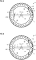
- FIG. 5 shows a plan view of the fire detector 1 according FIG. 4 along the viewing direction V marked there. It can now be seen in detail how the light beam L passes through the measuring space IR of the measuring chamber M and through the central area of the detector 1 into the light trap LF. The light beam L thereby intersects the main axis SA of the detector 1.
- the light trap LF is formed or formed in a cavity of the radial outer region RA of the main body G.
- the radial outer region RA of the main body G is limited by an inner wall IW, by which the optical measuring chamber M itself is limited. In the inner wall IW and the passage opening DL is recessed, through which the light beam L passes.
- the light trap LF has the form of a funnel TR, which extends around the main axis SA of the detector 1 in the radial outer region RA of the body G and the input side passes into a tubular bend, the entire region of the bend then directly the incident light beam L opposite. All light rays of the light beam L are then through the inner contour of the light trap LF in lateral, coaxial direction to the main axis SA of the detector 1 in the funnel TR of the light trap LF inside reflected. The light rays then run dead after repeated lossy reflection finally in the ever-narrowing funnel TR dead.
- FIG. 6 shows a plan view of the fire detector 1 according FIG. 4 by way of example two funnels TR formed in the radial outer region RA of the main body G as a light trap LF.
- the light trap LF which is twice as large, allows even more efficient light attenuation.
- SCH designates a cutting edge in the passage opening DL, which separates the two funnels TR from one another.
- FIG. 7 shows a fourth embodiment with a focusing element FOC of three optically reflective, adjacent segments according to the invention.
- Each segment in this case is part of an ellipsoid of revolution whose first focal point lies in the scattered light volume and whose second focal point lies directly in front of the photosensor. This makes a special compact design possible.
- the central opening OP in the detector hood 4 is covered by a dome DOM, leaving a plurality of radially outer, not further designated inlet openings.
- the DOM serves as a mechanical protection for a temperature sensor TS, which projects through the opening OP into the DOM.
- the inlet openings allow the passage of ambient air, so that a temperature detection by the temperature sensor TS is possible.
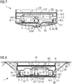
- FIG. 8 shows a fifth embodiment with a plurality of circumferentially distributed ultrasound transmitters US and with a microphone MIC according to the invention. They are aligned such that they radiate in operation in the direction of a mounting surface MF, to which the fire detector 1 is attached.
- a mounting base MS is shown, the radially as far outward extends, that the ultrasonic beam incident there is completely reflected from the surface of the mounting base MS.
- the surface of the mounting base MS at least in the region of the impact of the respective ultrasound beam is flat and smooth.
- ultrasonic transmitters US and ultrasonic receivers may be arranged on the circuit carrier, preferably at the radially outer end of the circuit carrier 9 and preferably alternately in the circumferential direction. Both the ultrasound transmitters US and the ultrasound receivers are acoustically aligned "obliquely" with the mounting surface MF. This is achieved in the present case by a respectively formed on the base body G reflection surface REF for ultrasonic waves UW.
- the control unit 10 of the fire detector 1 is set up to control the respective ultrasound transmitters for emitting an acoustic signal in the direction of the mounting surface MF, to temporally evaluate a respective ultrasound signal originating from the ultrasound receivers and reflected in the vicinity of the fire detector 1 and to output a fault message, if a detected object is within a predetermined distance around the fire detector 1.
- a microphone MIC for receiving the ultrasound waves UW may be provided, which is arranged centrally at the vertex SP of the detector hood 4.
- the reference numeral N denotes an insect screen or a net which prevents the penetration of insects and larger dust particles into the interior of the optical measuring chamber.
- the indicator LED LED is arranged on the inside LI of the circuit substrate 9. It shines in the opposite direction, ie in the direction of the circuit substrate 9 and through a through hole DO in the circuit substrate 9 through and further out into the environment of the fire detector 1.
- the light emitting diode LED is an example of the type Gullwing.
- the other sensors, such as photosensor 6 ', the heat radiation sensor 8, the gas sensor 7, the temperature sensor TS and the microphone MIC on the inside LI of the circuit substrate 9 may be arranged and through a corresponding passage opening OF in the circuit substrate 9, the respective measurement in the Detect environment of the fire detector 1.
- the photosensor 6 of the fire sensor 5, 6 may be arranged on the outside LA of the circuit substrate 9 and be optically aligned by a corresponding passage opening DO in the direction of the measuring chamber IR of the measuring chamber M.
Landscapes
- Chemical & Material Sciences (AREA)
- Analytical Chemistry (AREA)
- Business, Economics & Management (AREA)
- Emergency Management (AREA)
- Physics & Mathematics (AREA)
- General Physics & Mathematics (AREA)
- Fire-Detection Mechanisms (AREA)
Description
Die Erfindung betrifft einen Brandmelder, der einen Schaltungsträger sowie eine mit der Umgebungsluft kommunizierende Messkammer aufweist. Die Messkammer umfasst einen Brandsensor zur Erfassung einer Brandkenngrösse. Sie ist zudem in einem Meldergehäuse des Brandmelders aufgenommen. Die Messkammer umfasst einen Grundkörper sowie einen gegenüberliegenden Aufsetzkörper mit einem dazwischen ausgebildeten Messraum. Der Grundkörper ist zur Anbringung an einer Montagefläche, insbesondere an einem Meldersockel ausgebildet.The invention relates to a fire detector which has a circuit carrier and a measuring chamber communicating with the ambient air. The measuring chamber comprises a fire sensor for detecting a fire characteristic. It is also housed in a detector housing of the fire detector. The measuring chamber comprises a base body as well as an opposing attachment body with a measuring space formed therebetween. The main body is designed for attachment to a mounting surface, in particular on a detector base.
Die Messkammer kann auch als Detektionseinheit bezeichnet werden. Der Grundkörper und der Aufsetzkörper werden typischerweise im Rahmen der Montage zusammengefügt.The measuring chamber can also be referred to as a detection unit. The base body and the Aufsetzkörper are typically assembled during assembly.
Aus der
Aus der noch nicht veröffentlichten Europäischen Patentanmeldung der Anmelderin mit dem Anmeldeaktenzeichen
Aus der noch nicht veröffentlichten Europäischen Patentanmeldung der Anmelderin mit dem Anmeldeaktenzeichen 15180045.5 ist ein Streulichtrauchmelder bekannt, der eine mit der Umgebungsluft kommunizierende optische Messkammer aufweist. Letztere ist im Inneren eines Meldergehäuses aufgenommen und durch einen Grundkörper und durch eine Melderhaube des Meldergehäuses begrenzt. Im Grundkörper ist ein vorzugsweise ebener Schaltungsträger aufgenommen. Auf diesem sind angrenzend zur Messkammer eine Leuchtdiode und ein Photosensor in einer Streulichtanordnung angeordnet. Die Leuchtdiode und der Photosensor weisen jeweils eine zumindest nahezu orthogonal zum Schaltungsträger verlaufende optische Achse auf und liegen einer die Messkammer begrenzenden Innenseite der Melderhaube gegenüber. Ein Teil der Innenseite weist eine Spiegelfläche auf, welche der Leuchtdiode gegenüberliegt. Die Spiegelfläche weist eine derartige Spiegelgeometrie auf, dass ein Lichtkegel der Leuchtdiode einen Empfangsbereich des Photosensors in einem ersten Streulichtvolumen innerhalb der Messkammer schneidet.From the not yet published European patent application of the applicant with the registration file 15180045.5 a scattered light smoke detector is known, which has a communicating with the ambient air optical measuring chamber. The latter is accommodated inside a detector housing and limited by a main body and a detector hood of the detector housing. In the main body, a preferably planar circuit carrier is added. On this, a light emitting diode and a photosensor are arranged in a scattered light arrangement adjacent to the measuring chamber. The light-emitting diode and the photosensor each have an optical axis extending at least approximately orthogonally to the circuit carrier and lie opposite an inner side of the detector hood which delimits the measuring chamber. A part of the inside has a mirror surface, which is opposite to the light emitting diode. The mirror surface has a mirror geometry such that a light cone of the light-emitting diode intersects a reception region of the photosensor in a first scattered light volume within the measurement chamber.
Brandmelder sind allgemein bekannt. Sie können, wie auch der erfindungsgemässe Brandmelder, zum Anschluss an einem Melderbus bzw. an einer Melderlinie ausgebildet sein. Im Falle einer detektierten Brandkenngrösse erfolgt die Ausgabe einer Alarm- oder Warnmeldung auf den Melderbus. Beide Meldungen können alternativ oder zusätzlich über Funk und/oder am Brandmelder optisch und/oder akustisch ausgegeben werden. Die betrachteten, als Punktmelder ausgebildeten Brandmelder können alternativ oder zusätzlich für einen batteriegestützten Stand-Alone-Betrieb ausgebildet sein. Die Dokumente
Davon ausgehend ist es eine Aufgabe der Erfindung, einen besonders kompakten Brandmelder anzugeben.
Eine weitere Aufgabe der Erfindung ist, einen Brandmelder anzugeben, bei dem der Aufwand zur EMV-Abschirmung des Brandmelders reduziert ist.
Die Aufgabe wird mit den Gegenständen des Hauptanspruchs gelöst. Vorteilhafte Ausführungsformen der vorliegenden Erfindung sind in den abhängigen Ansprüchen angegeben.
Erfindungsgemäss liegt der Schaltungsträger mit einer dem Messraum zugewandten Innenseite am Aufsetzkörper an. Auf einer der Innenseite des Schaltungsträgers gegenüberliegenden Aussenseite ist zumindest ein weiterer Sensor jeweils zur Erfassung einer Messgrösse in der Umgebung und somit ausserhalb des Brandmelders und/oder eine Indikator-LED zur optischen Ausgabe einer Betriebsanzeige des Brandmelders in die Umgebung des Brandmelders angeordnet. Der Schaltungsträger ist zur Anordnung des Brandsensors sowie des zumindest weiteren Sensors und/oder der Indikator-LED vorgesehen.
Der Kern der Erfindung liegt in der doppelten Nutzung des Schaltungsträgers mit den dort applizierten Sensoren. Hier ist der eine Teil der Sensoren, d.h. der Brandsensor, Teil der angrenzenden Messkammer und sensorisch zur Messkammer hin ausgerichtet. Dagegen ist der andere Teil der Sensoren, d.h. der zumindest eine weitere Sensor, weg von der Messkammer in die angrenzende Umgebung des Brandmelders ausgerichtet.
Dadurch ist vorteilhaft keine separate Leitung zur elektrischen Verbindung der Sensoren mit dem Schaltungsträger erforderlich. Eine derartige Leitung muss häufig manuell an den Schaltungsträger angelötet werden.Fire detectors are well known. Like the fire detector according to the invention, they can be designed for connection to a detector bus or to a detector line. If a fire characteristic is detected, an alarm or warning message is output to the detector bus. Both messages can alternatively or additionally via radio and / or on Fire alarms are issued visually and / or acoustically. The considered fire detectors designed as point detectors can alternatively or additionally be designed for battery-supported stand-alone operation. The documents
On this basis, it is an object of the invention to provide a particularly compact fire detector.
Another object of the invention is to provide a fire detector in which the cost of EMC shielding the fire alarm is reduced.
The object is achieved with the objects of the main claim. Advantageous embodiments of the present invention are indicated in the dependent claims.
According to the invention, the circuit carrier bears against the mounting body with an inner side facing the measuring space. On one of the inside of the circuit substrate opposite outside at least one other sensor is arranged in each case for detecting a measured variable in the environment and thus outside the fire detector and / or an indicator LED for optical output of a fire alarm in the environment of the fire detector. The circuit carrier is provided for arranging the fire sensor and the at least one further sensor and / or the indicator LED.
The core of the invention lies in the double use of the circuit carrier with the sensors applied there. Here is the part of the sensors, ie the fire sensor, part of the adjacent measuring chamber and sensor aligned to the measuring chamber. By contrast, the other part of the sensors, ie the at least one further sensor, is directed away from the measuring chamber into the adjacent surroundings of the fire detector.
As a result, advantageously no separate line for the electrical connection of the sensors to the circuit carrier is required. Such a line must often be manually soldered to the circuit board.
Ein weiterer Vorteil ist, dass durch die direkte Anbringung der Sensoren auf dem Schaltungsträger der EMV-Einfluss auf die Sensoren drastisch reduziert wird. Dies ist insbesondere bei Sensoren der Fall, die als SMD-Bauteile für eine direkte Oberflächenmontage auf dem Schaltungsträger ausgebildet sind. Hier können aufwändige Abschirmmassnahmen entfallen.Another advantage is that the direct mounting of the sensors on the circuit carrier drastically reduces the EMC influence on the sensors. This is the case in particular for sensors which are designed as SMD components for direct surface mounting on the circuit carrier. Here elaborate shielding measures can be omitted.
Ein weiterer Vorteil liegt darin, dass kein Lichtleiter mehr zur optischen Ausleitung des von der Indikator-LED emittierten Lichts in die Umgebung des Brandmelders benötigt wird. Die Indikator-LED ist dazu vorgesehen, zyklisch einen Lichtimpuls auszugeben, um eine ordnungsgemässe Betriebsbereitschaft anzuzeigen und/oder das Vorliegen eines Brandalarm anzuzeigen, wie z.B. durch schnelleres Blinken.Another advantage is that no more optical fiber is needed for the optical discharge of the light emitted by the indicator LED light in the environment of the fire detector. The indicator LED is provided to cyclically output a light pulse to indicate proper operational readiness and / or to indicate the presence of a fire alarm, such as a fire alarm. by faster flashing.
Schliesslich ist der erfindungsgemässe Brandmelder mit erheblich reduziertem Fertigungs- und Montageaufwand herstellbar.Finally, the inventive fire detector with significantly reduced manufacturing and assembly costs can be produced.
Die mit der Umgebungsluft kommunizierende Messkammer kann eine optische Messkammer sein, wie z.B. ein sogenanntes Labyrinth. Eine solche Messkammer ist durchlässig für den Durchtritt von zu detektierenden Rauchteilchen und von zu detektierenden Brandgasen, wie z.B. Kohlenstoffmonoxid. Anderseits ist die Messkammer gegenüber direktem Umgebungslicht abgeschirmt. Die optische Messkammer kann auf dem Streulichtprinzip oder auf dem Extinktionsprinzip basieren. In diesem Fall weist der Brandsensor als Teil der optischen Messkammer eine Leuchtdiode sowie einen Photosensor auf. Alternativ oder zusätzlich kann die Messkammer einen oder mehrere Gassensoren als Brandsensor zur Detektion brandtypischer Rauchgase aufweisen. Ein derartiger Brandmelder wird auch als Rauchgasmelder bezeichnet. In diesem Fall ragt der Gassensor, wie z.B. ein sogenannter GasFET, in den Messraum der Messkammer hinein.The measuring chamber communicating with the ambient air may be an optical measuring chamber, such as a so-called labyrinth. Such a measuring chamber is permeable to the passage of smoke particles to be detected and to be detected combustion gases, such as carbon monoxide. On the other hand, the measuring chamber is shielded from direct ambient light. The optical measuring chamber can be based on the scattered light principle or on the extinction principle. In this case, the fire sensor has a light-emitting diode and a photosensor as part of the optical measuring chamber. Alternatively or additionally, the measuring chamber may have one or more gas sensors as a fire sensor for detecting flammable flue gases typical of fire. Such a fire detector is also referred to as a flue gas detector. In this case, the gas sensor, such as a so-called GasFET, protrudes into the measuring chamber of the measuring chamber.
Der Brandsensor ist dabei der Hauptsensor des Brandmelders.The fire sensor is the main sensor of the fire detector.
Nach einer Ausführungsform umfasst das Meldergehäuse ein Grundgehäuse und eine Melderhaube mit zumindest einer dazwischenliegend ausgebildeten Eintrittsöffnung. Letztere ist für den Durchtritt von Brandgasen und Rauchteilchen in die Messkammer des Brandmelders vorgesehen. Die Eintrittsöffnung kann schlitzförmig ausgebildet sein, wie z.B. mit einer Schlitzbreite im Bereich von 2 bis 5 mm. Es kann eine Vielzahl von kreisförmigen Eintrittsöffnungen mit einem Durchmesser im Bereich von 2 bis 10 mm im Meldergehäuse vorhanden sein. Die Melderhaube weist eine Haubenaussenseite, die weg vom Brandmelder zeigt, und eine gegenüberliegende Haubeninnenseite auf. Der Schaltungsträger liegt an der Haubeninnenseite an. Alternativ ist der Schaltungsträger mit einem maximalen Abstand A von 1.5 cm von der Haubeninnenseite beabstandet.According to one embodiment, the detector housing comprises a base housing and a detector hood with at least one inlet opening formed therebetween. The latter is intended for the passage of combustion gases and smoke particles into the measuring chamber of the fire detector. The entrance opening may be slit-shaped, e.g. with a slit width in the range of 2 to 5 mm. There may be a plurality of circular inlet openings with a diameter in the range of 2 to 10 mm in the detector housing. The detector hood has a hood outer side facing away from the fire detector, and an opposite hood inside. The circuit board is located on the hood inside. Alternatively, the circuit carrier with a maximum distance A of 1.5 cm from the hood inner side spaced.
Zudem liegt der zumindest eine weitere Sensor und/oder die Indikator-LED einer Öffnung in der Melderhaube gegenüber oder ragt in diese Öffnung oder ragt durch diese Öffnung hindurch.In addition, the at least one further sensor and / or the indicator LED is opposite an opening in the detector hood or protrudes into this opening or protrudes through this opening.
Vorzugsweise befindet sich die (zentrale) Öffnung an einer zentralen Position des Brandmelders, insbesondere an einem Scheitelpunkt der Melderhaube. Die Öffnung kann eine Aussparung sein. Sie weist vorzugsweise einen kreisförmigen Durchmesser auf. Der Durchmesser liegt insbesondere in einem Bereich von 1 bis 30 mm, vorzugsweise in einem Bereich von 3 bis 15 mm.Preferably, the (central) opening is located at a central position of the fire detector, in particular at a vertex of the detector hood. The opening may be a recess. It preferably has a circular diameter. The diameter is in particular in a range of 1 to 30 mm, preferably in a range of 3 to 15 mm.
Der Grundkörper und die Melderhaube können beide jeweils einstückig sein. Sie sind beide vorzugsweise Kunststoffspritzgrussteile. Der in der Melderhaube aufgenommene Schaltungsträger ist vorzugsweise eine ebene Leiterplatte.The main body and the detector hood can both be in one piece. They are both preferably plastic injection molding parts. The circuit carrier accommodated in the detector hood is preferably a planar printed circuit board.
Nach einer Ausführungsform der Erfindung weist der Brandmelder eine auf dem Schaltungsträger angeordnete Steuereinheit auf, vorzugsweise einen Mikrocontroller. Die Steuereinheit ist jeweils signal- oder datentechnisch mit dem Brandsensor zur Erfassung einer Brandkenngrösse sowie mit dem zumindest einen Sensor zur Erfassung der jeweiligen Messgrösse und/oder mit der Indikator-LED zur optischen Ausgabe der Betriebsanzeige verbunden. Die Steuereinheit weist eine Schnittstelle auf und ist dazu eingerichtet, durch die Schnittstelle eine jeweilige Sensorinformation zu erfassen und/oder durch die Schnittstelle eine jeweilige Alarmmeldung bei einer unzulässigen Abweichung von einem jeweiligen erfassten Sensormesswert auszugeben.According to one embodiment of the invention, the fire detector has a control unit arranged on the control unit, preferably a microcontroller. The control unit is each signal or data technology with the fire sensor for detecting a fire characteristic and with the at least one sensor for detecting the respective measured variable and / or connected to the indicator LED for optical output of the operating display. The control unit has an interface and is adapted to detect by the interface a respective sensor information and / or output by the interface a respective alarm message in an impermissible deviation from a respective detected sensor measured value.
Die Steuereinheit kann dazu eingerichtet sein, die jeweiligen Alarmmeldungen zu bündeln und als eine Alarmmeldung auszugeben. Sie kann zudem dazu eingerichtet sein, die jeweiligen Alarmmeldungen im Sinne eines Multikriterienmelders in Kombination zu bewerten und/oder zu gewichten. Sie kann schliesslich dazu eingerichtet sein, die weiteren Sensorsignale zur Prüfung des Brandsensorsignals auf Plausibilität hin heranzuziehen. Dadurch wird die Ausgabe eines Fehlalarms reduziert.The control unit may be configured to bundle the respective alarm messages and output them as an alarm message. It can also be set up to evaluate and / or weight the respective alarm messages in the sense of a multi-criteria alarm in combination. It can finally be set up to use the further sensor signals for testing the fire sensor signal for plausibility. This reduces the output of a false alarm.
Nach einer Ausführungsform ist der zumindest eine Sensor ein Temperatursensor und insbesondere ein Thermistor zur Erfassung einer Temperatur in der unmittelbaren Umgebung am Brandmelder. Vorzugsweise ist der Thermistor ein sogenannter NTC (für Negative Temperature Coefficient thermistor). Die Steuereinheit ist dazu eingerichtet, bei Überschreiten eines vom Temperatursensor erfassten Temperaturwerts, wie z.B. von 60°, und/oder bei Überschreiten eines Temperaturgradienten, wie z.B. von 5°/min, eine Temperaturinformation oder eine Alarmmeldung auszugeben.According to one embodiment, the at least one sensor is a temperature sensor and in particular a thermistor for detecting a temperature in the immediate vicinity of the fire detector. Preferably, the thermistor is a so-called NTC (for negative temperature coefficient thermistor). The control unit is set up, when a temperature value detected by the temperature sensor, such as a temperature value is exceeded. of 60 °, and / or when exceeding a temperature gradient, e.g. of 5 ° / min, to output a temperature information or alarm message.
Der zumindest eine weitere Sensor kann ein Lichtempfänger sein, wie z.B. eine Photodiode. Der Lichtempfänger ist zur Erfassung einer Umgebungshelligkeit vorgesehen. Die Steuereinheit ist dazu eingerichtet, bei Unterschreiten eines vom Photosensor erfassten Helligkeitswerts, z.B. von 10 Lux, nachts die Ausgabe einer optischen und/oder akustischen Warnmeldung zu unterdrücken, falls eine Batterie zur Energieversorgung des Brandmelders einen Spannungswert für einen niedrigen Ladezustand unterschreitet.The at least one further sensor may be a light receiver, such as a photodiode. The light receiver is provided for detecting an ambient brightness. The control unit is set up to suppress the output of an optical and / or acoustic warning message at night when a brightness value, for example 10 lux detected by the photosensor, drops below the output of an optical and / or acoustic warning message, if a battery is to supply energy of the fire detector falls below a voltage value for a low state of charge.
Weiterhin kann der zumindest eine weitere Sensor ein Gassensor zur Erfassung einer Rauchgaskonzentration sein, insbesondere von Kohlenstoffmonoxid. Der Gassensor ist z.B. ein Halbleiter-Gassensor und vorzugsweise ein sogenannter GasFET. Die Steuereinheit ist dazu eingerichtet, bei Überschreiten einer Mindestgaskonzentration, wie z.B. von 300 ppm Kohlenstoffmonoxid, eine Gasinformation und/oder eine Alarmmeldung auszugeben.Furthermore, the at least one further sensor may be a gas sensor for detecting a flue gas concentration, in particular carbon monoxide. The gas sensor is e.g. a semiconductor gas sensor, and preferably a so-called gas FET. The control unit is adapted to operate when a minimum gas concentration such as e.g. of 300 ppm carbon monoxide, a gas information and / or an alarm message.
Der zumindest eine weitere Sensor kann ein Wärmestrahlungssensor zur Erfassung von offenem Feuer oder lodernder Glut in der Umgebung des Brandmelders sein, insbesondere eine Thermosäule (Thermopile) oder ein Bolometer. Die Steuereinheit ist dazu eingerichtet, bei Detektion einer charakteristischen Flackerfrequenz, wie z.B. im Bereich von 8 bis 20 Hz im Sensorsignal des Wärmestrahlungssensors, eine Flammeninformation und/oder eine Alarmmeldung auszugeben. Der Wärmestrahlungssensor kann auch ein PIR-Sensor (für Passive InfraRed) zur Erfassung von Bewegungen, wie z.B. von Menschen, in der Umgebung des Brandmelders sein. Die Steuereinheit ist in diesem Fall dazu eingerichtet, eine Bewegungsinformation oder eine Alarmmeldung bei detektierter Bewegung von Objekten auszugeben.The at least one further sensor may be a thermal radiation sensor for detecting open fire or blazing embers in the vicinity of the fire detector, in particular a thermopile (thermopile) or a bolometer. The control unit is adapted to detect a characteristic flicker frequency, e.g. in the range of 8 to 20 Hz in the sensor signal of the heat radiation sensor to output a flame information and / or an alarm message. The thermal radiation sensor may also include a PIR sensor (for Passive InfraRed) for detecting movements such as motion. of people to be in the vicinity of the fire alarm. In this case, the control unit is set up to output movement information or an alarm message upon detected movement of objects.
Schliesslich kann der zumindest eine weitere Sensor ein Mikrophon zum Empfang von Ultraschallwellen aus der Umgebung des Bandmelders sein. Die Steuereinheit ist dazu eingerichtet, ein vom Mikrophon ausgegebenes Mikrophonsignal zeitlich auszuwerten, wie z.B. im zeitlichen Bezug auf Ultraschallwellen, die vorzugsweise zyklisch vom Brandmelder ausgesendet werden und die an Gegenständen in der Umgebung des Brandmelders reflektiert werden. Mittels der Steuereinheit ist dann eine Störmeldung ausgebbar, falls sich ein detektierter Gegenstand innerhalb einer vorgegebenen Distanz um den Brandmelder befindet. Vorzugsweise wird die Störmeldung nur dann ausgegeben, falls das Mikrophonsignal einen Mindestpegel überschreitet, sodass kleinere Mikrophonpegel von typischerweise kleineren und vernachlässigbaren Objekten ausser Acht gelassen werden können.Finally, the at least one further sensor may be a microphone for receiving ultrasonic waves from the surroundings of the band detector. The control unit is set up to evaluate a microphone signal output by the microphone in terms of time, for example with respect to temporal reference to ultrasonic waves, which are preferably emitted cyclically by the fire detector and which are reflected by objects in the vicinity of the fire detector. By means of the control unit, a fault message can then be output if a detected object is within a predetermined distance from the fire detector. Preferably, the fault message only then is output if the microphone signal exceeds a minimum level, so that smaller microphone levels of typically smaller and negligible objects can be disregarded.
Das Mikrophon kann alternativ oder zusätzlich zum Empfang von Geräuschen aus der Umgebung des Brandmelders vorgesehen und ausgebildet sein. Die Steuereinrichtung kann in diesem Fall dazu eingerichtet sein, eine Geräuschinformation oder eine Alarmmeldung auszugeben, wenn ein vom Mikrophon erfasster Geräuschpegel einen Mindestpegel überschreitet.The microphone may alternatively or additionally be provided and designed to receive noises from the environment of the fire detector. The control device may in this case be adapted to output a noise information or an alarm message when a microphone detected noise level exceeds a minimum level.
Nach einer weiteren Ausführungsform der Erfindung weist die Melderhaube eine (durchgehende) Öffnung in einem Scheitelpunkt der Melderhaube auf. Dabei liegt die Aussenseite des Schaltungsträgers der Öffnung gegenüber. Der Scheitelpunkt liegt vorzugsweise auf einer Symmetrieachse, insbesondere auf einer Rotationssymmetrieachse oder konstruktiven Hauptachse des Brandmelders. Typischerweise weisen Brandmelder eine in etwa rotationssymmetrische Bauform auf. Von dieser zentralen Stelle aus ist vorteilhaft eine gleichmässige "Rundumsicht" um den Brandmelder möglich. Zugleich ist an dieser zentralen Stelle eine vorteilhaft richtungsunabhängige Temperaturerfassung mittels des Temperatursensors möglich.According to a further embodiment of the invention, the detector hood has a (continuous) opening in a vertex of the detector hood. In this case, the outside of the circuit substrate is opposite to the opening. The vertex is preferably located on an axis of symmetry, in particular on a rotational symmetry axis or constructive main axis of the fire detector. Typically, fire detectors have an approximately rotationally symmetrical design. From this central point, a uniform "all-round view" around the fire detector is advantageously possible. At the same time, an advantageously direction-independent temperature detection by means of the temperature sensor is possible at this central point.
Einer weiteren Ausführungsform der Erfindung zufolge ist die Öffnung in der Melderhaube mit einer Abdeckung versehen, die für elektromagnetische Strahlung im Wellenlängenbereich von 400 nm bis 25 µm transparent ist. Die transparente Abdeckung kann aus einem Kunststoff oder aus Glas hergestellt sein. Sie kann die Öffnung vollständig verschliessen. Alternativ kann die transparente Abdeckung eine oder mehrere Durchlassöffnungen aufweisen, um einen Durchtritt von Umgebungsluft zur Temperaturerfassung oder zur Brandgasdetektion zu dem zumindest einen Sensor zu ermöglichen. Die transparente Abdeckung kann auch eine optische Linse zur Aufweitung des optischen Erfassungsbereichs ausformen. Dadurch sind offenes Feuer, lodernde Glut oder Bewegungen von grösseren Objekten, wie z.B. von Menschen, in einer grösseren Umgebung des Brandmelders vorteilhaft erfassbar.According to a further embodiment of the invention, the opening in the detector hood is provided with a cover which is transparent to electromagnetic radiation in the wavelength range from 400 nm to 25 μm. The transparent cover may be made of a plastic or of glass. It can completely close the opening. Alternatively, the transparent cover may have one or more passage openings to allow passage of ambient air for temperature detection or fire gas detection to the at least one sensor. The transparent cover may also form an optical lens for expanding the optical detection area. This is open fire, blazing embers or movements of larger objects, such as For example, by humans, advantageously detectable in a larger environment of the fire alarm.
Nach einer weiteren Ausführungsform ist auf dem Schaltungsträger zumindest der Wärmestrahlungssensor angeordnet. Die Öffnung in der Melderhaube ist mit einer nur für mittlere Infrarotstrahlung im Wellenlängenbereich von 2 bis 25 µm transparenten Abdeckung versehen.According to a further embodiment, at least the heat radiation sensor is arranged on the circuit carrier. The opening in the detector hood is provided with a cover which is transparent only for medium infrared radiation in the wavelength range from 2 to 25 μm.
Dadurch erscheint die Abdeckung im optisch sichtbaren Bereich eines Menschen als undurchsichtig, insbesondere als opak. Die transparente Abdeckung kann z.B. aus einem Kunststoff hergestellt sein, in welchem Streupartikel eingebracht sind. Der Kunststoff kann alternativ eine Strukturierung aufweisen, die sichtbares Licht zerstreut und mittlere Infrarotstrahlung zum Grossenteil passieren lässt. Mit "sichtbarem Licht" ist der für den Menschen optisch wahrnehmbare Wellenlängenbereich von etwa 380 nm bis 780 nm gemeint. Geeignete Werkstoffe für die Abdeckung sind z.B. aus der
Einer weiteren Ausführungsform der Erfindung umfasst der Brandsensor eine Leuchtdiode und einen Photosensor (6). Die Leuchtdiode und der Photosensor sind in einer Streulichtanordnung zur optischen Rauchdetektion nach dem Streulichtprinzip angeordnet. Alternativ oder zusätzlich sind die Leuchtdiode und der Photosensor sich gegenüberliegend zur optischen Rauchdetektion nach dem Extinktionsprinzip angeordnet. Auch in diesem Fall liegt das Messvolumen für die Durchlichtmessung im Messraum der Messkammer.In a further embodiment of the invention, the fire sensor comprises a light-emitting diode and a photosensor (6). The light emitting diode and the photosensor are arranged in a scattered light arrangement for optical smoke detection according to the scattered light principle. Alternatively or additionally, the light-emitting diode and the photosensor are arranged opposite each other for optical smoke detection according to the extinction principle. Also in this case, the measuring volume for the transmitted light measurement is in the measuring chamber of the measuring chamber.
Die Leuchtdiode kann eine einfarbige Leuchtdiode sein, welche monochromatisches Licht z.B. im Wellenlängenbereich von 380 bis 1000 nm aussendet. Sie kann eine Zweifarben-Leuchtdiode sein, welche dazu ausgebildet, ein erstes Lichtbündel oder einen ersten Lichtkegel in einem ersten Wellenlängenbereich von 380 bis 540 nm und/oder ein zweites Lichtbündel oder einen zweiten Lichtkegel in einem zweiten Wellenlängenbereich von 750 bis 1000 nm für eine Rauchdetektion nach dem Zweifarbenprinzip auszusenden. Durch die farbspezifische Auswertung des Photosensorsignals ist eine brandtechnische Analyse der detektierten Rauchteilchen hinsichtlich ihrer Teilchengrösse und somit eine Bestimmung des Rauchtyps möglich.The light-emitting diode can be a single-color light-emitting diode which emits monochromatic light, for example in the wavelength range from 380 to 1000 nm. It can be a two-color light-emitting diode which is designed to generate a first light beam or a first light cone in a first wavelength range from 380 to 540 nm and / or a second light beam or a second light cone in a second wavelength range from 750 to 1000 nm for smoke detection according to the two-color principle send out. Due to the color-specific evaluation of the photosensor signal, a fire technical analysis of the detected smoke particles with regard to their particle size and thus a determination of the type of smoke is possible.
Nach einer weiteren Ausführungsform der Erfindung sind die Leuchtdiode und der Photosensor optisch auf ein gemeinsames Streulichtvolumen innerhalb des Messraums ausgerichtet. Der Photosensor ist derart auf dem Schaltungsträger angeordnet, dass eine durch das Zentrum des Brandmelders verlaufende Hauptachse oder Symmetrieachse sowohl durch das Streulichtvolumen als auch durch den Photosensor verläuft. Dadurch ist eine weitgehend richtungsunabhängige Rauchdetektion vorteilhaft möglich.According to a further embodiment of the invention, the light emitting diode and the photosensor are optically aligned to a common scattered light volume within the measuring space. The photosensor is arranged on the circuit carrier in such a way that a main axis or axis of symmetry extending through the center of the fire detector extends both through the scattered light volume and through the photosensor. As a result, a largely direction-independent smoke detection is advantageously possible.
Einer besonders vorteilhaften Ausführungsform der Erfindung zufolge sind die Leuchtdiode und der Photosensor derart auf dem Schaltungsträger angeordnet und ausgerichtet, dass diese jeweils eine zumindest nahezu orthogonal zum Schaltungsträger verlaufende optische Achse aufweisen. Ein Teil der Innenseite des Grundkörpers weist eine Spiegelfläche auf, welche der Leuchtdiode gegenüberliegt. Die Spiegelfläche weist eine derartige Spiegelgeometrie auf, dass ein Lichtkegel der Leuchtdiode einen Empfangsbereich des Photosensors in einem Streulichtvolumen innerhalb des Messraums der Messkammer schneidet. Die Spiegelfläche kann z.B. eine sphärische Geometrie aufweisen, welche eine Bündelung des einfallenden Lichtbündels bewirkt. Die Spiegelfläche kann Teil der Oberfläche z.B. einer Kugel, eines Ellipsoids oder eines Paraboloids sein.According to a particularly advantageous embodiment of the invention, the light-emitting diode and the photosensor are arranged and aligned on the circuit carrier such that they each have an optical axis extending at least approximately orthogonally to the circuit carrier. A part of the inside of the main body has a mirror surface, which is opposite to the light emitting diode. The mirror surface has a mirror geometry such that a light cone of the light-emitting diode intersects a receiving region of the photosensor in a scattered light volume within the measuring chamber of the measuring chamber. The mirror surface may e.g. have a spherical geometry, which causes a bundling of the incident light beam. The mirror surface may be part of the surface e.g. a ball, an ellipsoid or a paraboloid.
Die Spiegelfläche kann eine plane oder eine konkave Fläche aufweisen. Sie kann eine silbrige Folie oder ein Blechstück aus Metall sein, wie z.B. aus Aluminium oder Stahl. Die Folie kann auf der Innenseite des Grundkörpers aufgeklebt werden. Das Blechstück kann an dieser Innenseite z.B. angeklebt oder beim Spritzguss des Grundkörpers mit angebracht werden. Die Spiegelfläche kann auch eine metallisierte Fläche sein, die z.B. mittels eines Bedampfungsverfahrens im Vakuum aufgebracht wird. Die Spiegelfläche kann auch ein Kunststoffspiegel mit einer glänzenden oder polierten Fläche sein, wie z.B. aus schwarzem Kunststoff.The mirror surface may have a plane or a concave surface. It may be a silvery foil or a sheet metal piece, such as aluminum or steel. The film can be glued on the inside of the body. The sheet metal piece can be glued to this inside, for example, or attached during injection molding of the body. The mirror surface may also be a metallized surface which For example, by means of a vapor deposition in vacuum is applied. The mirror surface may also be a plastic mirror with a shiny or polished surface, such as black plastic.
Die Verwendung der Innenseite des Grundkörpers als Spiegel bzw. als Reflektor, um das von der Leuchtdiode orthogonal zum Schaltungsträger ausgesandte Lichtbündel durch einen zentralen Bereich im Inneren des Meldergehäuses zu lenken, ermöglicht vorteilhaft die Herstellung eines besonders kompakten und zugleich konstruktiv einfachen Brandmelders.The use of the inside of the body as a mirror or as a reflector to direct the light emitted by the light emitting diode orthogonal to the circuit substrate light beam through a central region in the interior of the detector housing, advantageously allows the production of a particularly compact and at the same time structurally simple fire detector.
Im Aufsetzkörper sind Ausnehmungen für den Brandsensor, wie z.B. für die Leuchtdiode und für den Photosensor, vorhanden. Der Aufsetzkörper weist vorzugsweise zumindest eine Blende für die Leuchtdiode und für den Photosensor, die Lichtfalle und/oder lichtabsorbierende Strukturen als integrale Teile des Aufsetzkörpers auf bzw. formt diese aus. Der Aufsetzkörper ist vorzugsweise ein schwarzes Kunststoffspritzgussteil. Er kann davon unabhängig mit einem schwarzen Farbauftrag versehen sein. Insbesondere überdeckt der Aufsetzkörpers bis auf die zuvor genannten Ausnehmungen im Wesentlichen die gesamte, dem Messraum der Messkammer zugewandte Innenseite des Schaltungsträgers. Der Schaltungsträger liegt somit wie bei einem Sandwich zwischen dem Aufsetzkörper und der Melderhaube. Dies ermöglicht vorteilhaft eine besonders kompakte Bauweise sowie eine einfache Integration der weiteren Sensoren sowie der Indikator-LED auf dem Schaltungsträger. Letzterer grenzt in vorteilhafter Weise direkt an die Melderhaube und somit auch an die zu überwachende Umgebung ausserhalb des Brandmelders.In the seating body are recesses for the fire sensor, such as e.g. for the light-emitting diode and for the photosensor, available. The attachment body preferably has or forms at least one diaphragm for the light-emitting diode and for the photosensor, the light trap and / or light-absorbing structures as integral parts of the attachment body. The attachment body is preferably a black plastic injection molded part. He can be independently provided with a black paint job. In particular, the mounting body covers substantially all of the measuring space of the measuring chamber facing the inside of the circuit substrate except for the aforementioned recesses. The circuit carrier is thus as in a sandwich between the Aufsetzkörper and the detector hood. This advantageously allows a particularly compact design and easy integration of the other sensors and the indicator LED on the circuit board. The latter is advantageously adjacent directly to the detector hood and thus also to the environment to be monitored outside the fire alarm.
Die Melderhaube kann z.B. eine sphärische, gewölbte Bauform oder die Form eines zylindrischen Deckels mit kreisförmigen planen Boden aufweisen. Sie ist üblicherweise aus einem weissen Kunststoff hergestellt.The detector hood may, for example, have a spherical, arched design or the shape of a cylindrical lid with a circular flat bottom. It is usually made of a white plastic.
Nach einer weiteren Ausführungsform der Erfindung weist ein Teil der Innenseite des Grundkörpers ein Fokussierelement auf, welches dem Photosensor gegenüberliegt und welches eine derartige Fokussiergeometrie aufweist, dass Streulicht aus dem Streulichtvolumen in Richtung zum Photosensor reflektiert wird. Insbesondere ist das Fokussierelement derart angeordnet, dass die konstruktive Hauptachse bzw. die Rotationssymmetrieachse des Brandmelders durch die (geometrische) Mitte des Fokussierelements und durch das Streulichtvolumen verläuft sowie mit der optischen Empfangsachse des Photosensors fluchtet. Durch das zusätzlich auf den Photosensor auftreffende Streulicht wird die Empfindlichkeit des Photosensors vorteilhaft erhöht.According to a further embodiment of the invention, a part of the inside of the base body has a focusing element, which is opposite to the photosensor and which has such a focus geometry that scattered light is reflected from the scattered light volume in the direction of the photosensor. In particular, the focusing element is arranged such that the constructive main axis or the rotational axis of symmetry of the fire detector extends through the (geometric) center of the focusing element and through the scattered light volume and is aligned with the optical receiving axis of the photosensor. Due to the additionally incident on the photosensor scattered light, the sensitivity of the photosensor is advantageously increased.
Das Fokussierelement weist nach einer weiteren Ausführungsform der Erfindung mehrere optisch reflektierende sowie aneinander angrenzende Segmente auf. Jedes Segment ist Teil eines Ellipsoids, insbesondere eines Rotationsellipsoids, dessen erster Brennpunkt im Streulichtvolumen liegt und dessen zweiter Brennpunkt unmittelbar vor dem Photosensor liegt. Mit "unmittelbar" ist gemeint, dass der zweite Brennpunkt sich in einem Abstand von maximal 5 mm vor der lichtempfindlichen Sensorschicht des Photosensors befindet. Durch die segmentierte Ausführung des Fokussierelements resultiert eine geringe Bauhöhe des Fokussierelements. Dadurch ragt das Fokussierelement weniger in den Messraum der Messkammer und bildet somit vorteilhaft ein geringeres Strömungshindernis gegenüber eindringendem Rauch. Das Fokussierelement ist vorzugsweise als "schwarzer" Spiegel ausgebildet. Es ist insbesondere ein glänzendes Teil eines aus schwarzem Kunststoff hergestellten Spritzgussteils des Grundkörpers.The focusing element has according to a further embodiment of the invention, a plurality of optically reflective and adjacent segments. Each segment is part of an ellipsoid, in particular an ellipsoid of revolution, whose first focal point lies in the scattered light volume and whose second focal point lies directly in front of the photosensor. By "immediate" is meant that the second focus is at a distance of not more than 5 mm in front of the photosensitive sensor layer of the photosensor. The segmented design of the focusing element results in a low overall height of the focusing element. As a result, the focusing element protrudes less into the measuring chamber of the measuring chamber and thus advantageously forms a smaller flow obstacle against penetrating smoke. The focusing element is preferably designed as a "black" mirror. In particular, it is a shiny part of an injection molded part made of black plastic of the main body.
Nach einer weiteren Ausführungsform der Erfindung weist die der Leuchtdiode gegenüberliegende Spiegelfläche eine derartige Spiegelgeometrie auf, dass der Lichtkegel der Leuchtdiode den Messraum durchquert und in eine lichtabsorbierende Lichtfalle mündet.According to a further embodiment of the invention, the mirror surface opposite the light-emitting diode has a mirror geometry such that the light cone of the light-emitting diode traverses the measuring space and opens into a light-absorbing light trap.
Durch die Fokussierung und gezielte Lenkung des Lichtbündels ist vorteilhaft eine effektive gerichtete Einleitung des Lichtbündels in die dafür vorgesehene Lichtfalle mit einer nahezu vollständigen Lichtabsorption möglich.By focusing and targeted steering of the light beam is advantageously an effective directional introduction of the light beam in the designated light trap with a nearly complete absorption of light possible.
Die Lichtfalle ist vorzugsweise topf- oder trichterförmig ausgebildet. Sie weist insbesondere im Bezug auf die Haupteinfallrichtung der von der Spiegelfläche reflektierten Lichtstrahlen derart geometrisch orientierte Flächen und/oder Riffelungen auf, dass sich die dort einfallenden Lichtstrahlen nach einigen Reflexionen auslöschen bzw. "totlaufen".The light trap is preferably pot-shaped or funnel-shaped. In particular with respect to the main incident direction of the light rays reflected by the mirror surface, it has geometrically oriented surfaces and / or corrugations such that the light rays incident thereon cancel out or "run dead" after a number of reflections.
Dadurch verringert sich vorteilhaft der sogenannte Grundpuls. Es gelangt somit weniger an den Wänden und Komponenten der optischen Messkammer reflektiertes Licht zum Photosensor.This advantageously reduces the so-called basic pulse. It thus passes less to the walls and components of the optical measuring chamber reflected light to the photosensor.
Nach einer besonders vorteilhaften Ausführungsform der Erfindung ist die Lichtfalle in Form eines Trichters im Grundkörper ausgeformt. Der Trichter erstreckt sich in einem radialen Aussenbereich des Grundkörpers im Wesentlichen koaxial um eine durch das Zentrum des Brandmelders verlaufende Hauptachse. Die Trichterform ermöglicht vorteilhaft eine noch effektivere Lichtabsorption durch eine Vielzahl von Reflexion innerhalb des Trichters. Ein weiterer Vorteil liegt in der konstruktiv einfachen räumlichen Integration des Trichters in den radialen Aussenbereich des Grundkörpers.According to a particularly advantageous embodiment of the invention, the light trap is shaped in the form of a funnel in the base body. The funnel extends in a radial outer region of the base body substantially coaxially about a main axis extending through the center of the fire detector. The funnel shape advantageously enables even more effective light absorption by a large number of reflections within the funnel. Another advantage lies in the structurally simple spatial integration of the funnel in the radial outer region of the body.
Einer weiteren Ausführungsform der Erfindung zufolge ist auf dem Schaltungsträger eine Mehrzahl von Ultraschallsendern angeordnet. Sie sind derart ausgerichtet, dass diese im Betrieb in Richtung auf eine Montagefläche, an welcher der Brandmelder angebracht ist, strahlen.According to a further embodiment of the invention, a plurality of ultrasound transmitters are arranged on the circuit carrier. They are aligned so that they radiate in operation towards a mounting surface on which the fire detector is mounted.
Auf dem Schaltungsträger ist eine Mehrzahl von Ultraschallempfängern oder eine Mehrzahl von Ultraschalltransceivern jeweils als Baueinheit aus einem Ultraschallsender und aus einem Ultraschallempfänger angeordnet. Die Ultraschallempfänger sind in Richtung auf die Montagefläche ausgerichtet, um im Betrieb aus dieser Richtung Ultraschallwellen zu erfassen. Alternativ dazu ist zumindest ein Mikrophon als weiterer Sensor des Brandmelders derart auf dem Schaltungsträger angeordnet, dass dieses der Öffnung in der Melderhaube gegenüberliegt, in diese Öffnung ragt oder durch diese Öffnung hindurchragt. Die Öffnung ist vorzugsweise im Scheitelpunkt der Melderhaube angeordnet. Die Steuereinheit ist dazu eingerichtet, die jeweiligen Ultraschallsender zum Aussenden eines akustischen Signals in Richtung auf die Montagefläche anzusteuern, ein jeweiliges von den Ultraschallempfängern oder von dem Mikrophon stammendes, an Gegenständen in der Umgebung des Brandmelders reflektiertes Ultraschallsignal zeitlich auszuwerten und eine Störmeldung auszugeben, falls sich innerhalb einer vorgegebenen Distanz um den Brandmelder, wie z.B. in einer Distanz von 50 cm um den Brandmelder, ein detektierter Gegenstand befindet. Vorzugsweise ist die Störmeldung ausgebbar, falls zusätzlich das vom Mikrophon empfangene Ultraschallsignal einen Mindestpegel überschreitet.On the circuit carrier, a plurality of ultrasonic receivers or a plurality of ultrasonic transceivers are each arranged as a structural unit of an ultrasonic transmitter and an ultrasonic receiver. The ultrasonic receivers are oriented towards the mounting surface to to detect ultrasonic waves during operation from this direction. Alternatively, at least one microphone as a further sensor of the fire detector is arranged on the circuit carrier such that it lies opposite the opening in the detector hood, protrudes into this opening or protrudes through this opening. The opening is preferably arranged at the apex of the detector hood. The control unit is set up to control the respective ultrasound transmitters for emitting an acoustic signal in the direction of the mounting surface, to evaluate in time a respective ultrasound signal originating from the ultrasound receivers or from the microphone and reflected from objects in the surroundings of the fire detector and to output a fault message if within a predetermined distance around the fire detector, such as at a distance of 50 cm around the fire detector, a detected object is located. Preferably, the fault message can be output if, in addition, the ultrasound signal received by the microphone exceeds a minimum level.
Dadurch lassen sich vorteilhaft grössere Objekte, wie Stellwände oder Einbauschränke, in der Umgebung um den Brandmelder detektieren, die möglicherweise strömungsabschirmend für zu detektierenden Rauch oder Brandgase sind.As a result, advantageously larger objects, such as partitions or built-in cabinets, can be detected in the environment around the fire detector, which may possibly be flow-shielding for smoke or combustion gases to be detected.
Die Montagefläche ist typischerweise die Decke in einem Gebäude. Sie kann alternativ eine Wand sein. Die Montagefläche kann auch ein Montagesockel sein, auf dem der Brandmelder insbesondere lösbar anbringbar ist und der seinerseits an der Decke bzw. an der Wand befestigt ist. Der Montagesockel ist insbesondere plattenförmig und vorzugsweise kreisförmig ausgebildet. Der Montagesockel kann sich in radial soweit nach aussen erstrecken, das ein vom jeweiligen Ultraschallsender bzw. Ultraschalltransceiver abgestrahltes Ultraschallsignal bzw. Ultraschallbündel auf den Montagesockel trifft. Diese Kombination aus einem erfindungsgemässen Brandmelder mit einem derartigen Montagesockel hat den Vorteil, dass unabhängig von der Qualität der Decke bzw. der Wand im Bezug auf die Reflexionseigenschaft für Ultraschallwellen immer definierte Reflexionseigenschaften vorliegen.The mounting surface is typically the ceiling in a building. It can alternatively be a wall. The mounting surface may also be a mounting base on which the fire detector is in particular releasably attachable and which in turn is attached to the ceiling or on the wall. The mounting base is in particular plate-shaped and preferably circular. The mounting base may extend radially outward to the extent that hits an ultrasonic signal or ultrasound beam emitted by the respective ultrasound transmitter or ultrasound transceiver onto the mounting base. This combination of a fire detector according to the invention with such a mounting base has the advantage that regardless of the quality of the ceiling or the wall in relation reflection properties always present on the reflection property for ultrasonic waves.
Nach einer Ausführungsform weist der Brandmelder zumindest eine vorzugsweise im Grundkörper ausgebildete Reflexionsfläche im Strahlengang vom jeweiligen Ultraschallsender zur Montagefläche auf. Die Reflexionsflächen können derart ausgeformt sein, dass sie bündelnde Eigenschaften für die ausgesandten Ultraschallwellen aufweisen. Insbesondere sind die Reflexionsflächen konkav ausgeformt.According to one embodiment, the fire detector has at least one preferably formed in the base body reflection surface in the beam path from the respective ultrasonic transmitter to the mounting surface. The reflection surfaces may be formed such that they have bundling properties for the emitted ultrasonic waves. In particular, the reflection surfaces are concave.
Der besondere Vorteil ist, dass die Ultraschallsender, Ultraschallempfänger und als Kombination davon Ultraschalltransceiver plan auf dem Schaltungsträger appliziert werden können. Die Strahllenkung erfolgt durch die Reflexionsflächen. Insbesondere sind die zuvor genannten Ultraschallbaueinheiten auf der dem Innenraum des Brandmelders zugewandten Innenseite des Schaltungsträgers angeordnet und vorzugsweise am radialen Aussenrand des Schaltungsträgers.The particular advantage is that the ultrasound transmitter, ultrasound receiver and, as a combination thereof, ultrasound transceivers can be flatly applied to the circuit carrier. The beam steering takes place through the reflection surfaces. In particular, the abovementioned ultrasound units are arranged on the inside of the circuit carrier facing the interior of the fire detector, and preferably on the radial outer edge of the circuit carrier.
Die Erfindung sowie vorteilhafte Ausführungen der vorliegenden Erfindung werden am Beispiel der nachfolgenden Figuren erläutert. Dabei zeigen:
- FIG 1
- eine erste Ausführungsform mit einer Vielzahl weiterer Sensoren sowie mit einer Indikator-LED im Bereich einer zentralen Öffnung in der Melderhaube eines Brandmelders gemäss der Erfindung,
- FIG 2
- eine Draufsicht auf die Melderhaube mit der zentralen Öffnung entlang der in
FIG 1 eingezeichneten Blickrichtung II, - FIG 3
- eine zweite Ausführungsform mit einer in einem Zwischenraum zwischen der Melderhaube und einem Aufsetzkörper der Messkammer ausgebildeten Lichtfalle gemäss der Erfindung,
- FIG 4
- eine dritte Ausführungsform mit einem zentral angeordneten Photosensor und mit einem gegenüberliegendem Fokussierelement gemäss der Erfindung sowie mit einem im radialen Aussenbereich des Grundkörpers ausgeformten Trichter als Lichtfalle gemäss der Erfindung,
- FIG 5
- eine Draufsicht auf den Brandmelder gemäss
FIG 4 entlang der dort eingezeichneten Blickrichtung V, - FIG 6
- eine Draufsicht auf den Brandmelder gemäss
FIG 4 mit beispielhaft zwei im radialen Aussenbereich des Grundkörpers ausgeformten Trichtern als Lichtfalle, - FIG 7
- eine vierte Ausführungsform mit einem Fokussierelement aus drei optisch reflektierenden, aneinander angrenzenden Segmenten gemäss der Erfindung, und
- FIG 8
- eine fünfte Ausführungsform mit mehreren in Umfangsrichtung verteilt angeordneten Ultraschallsendern und mit einem Mikrophon gemäss der Erfindung.
- FIG. 1
- a first embodiment with a plurality of further sensors and with an indicator LED in the region of a central opening in the detector hood of a fire detector according to the invention,
- FIG. 2
- a plan view of the detector hood with the central opening along the in
FIG. 1 marked line of sight II, - FIG. 3
- a second embodiment with a formed in a space between the detector hood and a Aufsetzkörper the measuring chamber light trap according to the invention,
- FIG. 4
- a third embodiment with a centrally located photosensor and with an opposite focusing element according to the invention and with a formed in the radial outer region of the body funnel as a light trap according to the invention,
- FIG. 5
- a plan view of the fire detector according to
FIG. 4 along the viewing direction V marked there, - FIG. 6
- a plan view of the fire detector according to
FIG. 4 by way of example two funnels formed in the radial outer region of the main body as a light trap, - FIG. 7
- a fourth embodiment with a focusing element of three optically reflective, adjacent segments according to the invention, and
- FIG. 8
- a fifth embodiment with a plurality of circumferentially distributed ultrasound transmitters and with a microphone according to the invention.
Es ist gemäss der Erfindung ein Schaltungsträger 9 in der Melderhaube 4 mit einer dem Messraum IR zugewandten Innenseite LI und mit einer dieser gegenüberliegenden Aussenseite LA angeordnet. Die Aussenseite LA des Schaltungsträgers 9 liegt direkt an einer Innenseite MI der Melderhaube 4 an. Auf dem Schaltungsträger 9 sind ein Temperatursensor TS angeordnet, insbesondere ein NTC, ein weiterer Photosensor 6' zur Messung der Umgebungshelligkeit, ein Gassensor 7, z.B. ein GasFET zur CO-Messung, ein Wärmestrahlungssensor 8, insbesondere ein Thermopile, zur Flammen- und Bewegungserkennung, ein Mikrophon MIC sowie eine Indikator-LED LED zur optischen Betriebsbereitanzeige in die Umgebung angeordnet. Die zuvor genannten Bauelemente TS, 6', 7, 8, MIC, LED sind derart auf dem Schaltungsträger 9 angeordnet, dass sie der Öffnung OP gegenüberliegen. Im vorliegenden Beispiel weist die Öffnung OP einen Durchmesser im Bereich von 5 bis 10 mm sowie eine Tiefe von etwa 2 mm auf.According to the invention, a
Im vorliegenden Beispiel ist die Öffnung OP in einem Scheitelpunkt SP der Melderhaube 4, d.h. mittig oder zentral in der Melderhaube 4 angeordnet. Es liegt somit die Aussenseite LA des Schaltungsträgers 9 der Öffnung OP direkt gegenüber. Mit "mittig" oder "zentral" ist gemeint, dass die konstruktive Hauptachse oder Symmetrieachse SA des Brandmelders 1 durch die Öffnung OP hindurchgeht.In the present example, the opening OP is arranged in a vertex SP of the detector hood 4, ie centrally or centrally in the detector hood 4. It is thus the outside LA of the
Gemäss dem vorliegenden Beispiel ist die Öffnung OP mit einer Abdeckung AB versehen, welche für elektromagnetische Strahlung im Wellenlängenbereich von 400 nm bis 25 µm transparent ist. Die Abdeckung AB ist ferner als optische Linse OL zur Aufweitung des Erfassungsbereichs W für Wärmestrahlung sowie für Licht ausgeformt. Die gezeigte optische Linse OL bildet zudem einen radial aussenliegenden umlaufenden Spalt zu Aussenseite MA der Melderhaube 4 hin aus, sodass Umgebungsluft zur Bestimmung der Umgebungstemperatur und der Konzentration von Brandgasen sowie Schallwellen zur Erfassung von akustischen Signalen in die Öffnung OP mit den dort befindlichen weiteren Sensoren TS, 6', 7, 8, MIC gelangen können.According to the present example, the opening OP is provided with a cover AB, which is transparent to electromagnetic radiation in the wavelength range from 400 nm to 25 μm. The cover AB is further formed as an optical lens OL for widening the detection area W for heat radiation as well as for light. The optical lens OL shown also forms a radially outer circumferential gap to the outside MA of the detector hood 4 out, so ambient air to determine the ambient temperature and the concentration of combustion gases and sound waves to detect acoustic signals in the opening OP with the other sensors located there TS , 6 ', 7, 8, MIC can arrive.
Die Messkammer M ist im vorliegenden Beispiel eine optische Messkammer M. Die gezeigte Messkammer M ist durch Lichtabschirmelemente in Form von Lamellen LAM gegenüber direktem Umgebungslicht abgeschirmt. Die Abschirmelemente LAM sind vorzugsweise integraler Bestandteil des Grundkörpers G oder des Aufsetzkörpers A. Die optische Messkammer M basiert im vorliegenden Beispiel auf dem Streulichtprinzip. Der Brandsensor 5, 6 ist Teil der optischen Messkammer M. Er umfasst eine Leuchtdiode 5 sowie einen Photosensor 6 in einer Streulichtanordnung zur optischen Rauchdetektion. Dem Photosensor 6 ist zudem eine Linse 11 zur optischen Bündelung des Streulichts auf den Photosensor 6 vorgeschaltet. Der gezeigte Brandmelder 1 ist somit in erster Linie ein Streulichtrauchmelder. Sowohl Leuchtdiode 5 als auch Photosensor 6 sind derart auf dem ebenen Schaltungsträger 9 angeordnet, dass ihre optischen Achsen orthogonal oder nahezu orthogonal zum Schaltungsträger 9 und somit parallel zueinander verlaufen. Im bevorzugten praktischen Fall sind die Leuchtdiode 5 und der Photosensor 6 SMD-Bauelemente, die mit hoher Präzision und automatisiert auf dem Schaltungsträger 9 mit dafür vorgesehenen Kontaktierungsflächen appliziert werden können.In the present example, the measuring chamber M is an optical measuring chamber M. The measuring chamber M shown is shielded from direct ambient light by light-shielding elements in the form of lamellae LAM. The shielding elements LAM are preferably an integral part of the main body G or the Aufsetzkörpers A. The optical measuring chamber M is based in the present example on the scattered light principle. The
Weiterhin weist ein Teil der Innenseite GI des Grundkörpers G eine Spiegelfläche S auf, die der Leuchtdiode 5 gegenüberliegt. Die Spiegelfläche S ist so bemessen, dass der von der Leuchtdiode 5 ausgesandte Lichtkegel L vollständig (und nur) auf die Spiegelfläche S trifft. Die Leuchtdiode 5 ist im vorliegenden Beispiel eine Zweifarben-Leuchtdiode, die dazu eingerichtet ist, ein rotes Lichtbündel L und/oder ein blaues Lichtbündel L entlang eines im Wesentlichen gleichen optischen Pfads auszusenden. Die Spiegelfläche S weist eine derartige Spiegelgeometrie auf, dass der Lichtkegel L bzw. das Lichtbündel einen Empfangsbereich E des Photosensors 6 in einem Streulichtvolumen Z innerhalb der optischen Messkammer M schneidet. Dabei gelangt Streulicht nur von Teilchen im Streulichtvolumen Z zur Detektion durch den Photosensor 6. Typischerweise ist der Empfangsbereich E ein Empfangskegel.Furthermore, a part of the inner side GI of the base body G has a mirror surface S, which is opposite to the light-emitting
Weiter gemäss der Erfindung sind Blenden BL, eine Lichtfalle LF und/oder lichtabsorbierende Strukturen AB in Form von Riffelungen zur Minimierung des Grundpulses in der optischen Messkammer M vorgesehen. Im Beispiel sind die zuvor genannten konstruktiven Elemente BL, LF, AB integrale Elemente eines schwarz glänzenden oder matten Aufsetzkörpers A, der zur Abdeckung oder Anbringung am Schaltungsträger 9 angebracht ist. Der Aufsetzkörper A ist im Beispiel ein einstückiges Kunststoffspritzgussteil. Es kann auch aus mehreren Kunststoffteilen untrennbar zusammengesetzt sein. Im Aufsetzkörper A sind weiterhin zwei Ausnehmungen in Form von Durchbrüchen für die Leuchtdiode 5 und für den Photosensor 6 vorhanden. Vorzugsweise weist auch die Innenseite GI des Grundkörpers G lichtabsorbierende Strukturen AB wie z.B. in Form von Riffelungen oder geriffelten Flächen auf. Davon ausgenommen ist die Spiegelfläche S, die z.B. durch ein angebrachtes spiegelndes Blechstück oder durch aufgedampftes Metall, wie z.B. Aluminium, realisiert werden kann.Further according to the invention, apertures BL, a light trap LF and / or light-absorbing structures AB are provided in the form of corrugations for minimizing the fundamental pulse in the optical measuring chamber M. In the example, the aforementioned constructive elements BL, LF, AB are integral elements of a black glossy or matt Aufsetzkörpers A, which is mounted for covering or attachment to the
Im gezeigten Beispiel weist die Spiegelfläche S eine derartige Spiegelgeometrie auf, dass der Lichtkegel L bzw. das Lichtbünde der Leuchtdiode 5 nach seiner Spiegelung faktisch berührungsfrei den Messraum IR der Messkammer M durchquert und in die lichtabsorbierende Lichtfalle LF mündet. Das dort einfallende, nicht an Rauchpartikeln gestreute Licht wird dort wirksam absorbiert.In the example shown, the mirror surface S has such a mirror geometry that the light cone L or the light bundles of the light-emitting
Der gezeigte Brandmelder 1 weist zur Ansteuerung und Auswertung der optoelektronischen Bauelemente 5, 6, das heisst der Leuchtdiode 5 und des Photosensors 6, sowie zur Ausgabe einer Alarmmeldung eine elektronische Steuereinheit 10 auf. Diese ist vorzugsweise ein Mikrocontroller und auf dem Schaltungsträger 9 appliziert. Die Steuereinheit 10 ist dazu eingerichtet bzw. programmiert, die Leuchtdiode 5 zumindest mittelbar gepulst anzusteuern und ein entsprechendes vom Photosensor 6 stammendes Sensorsignal auszuwerten. Hierzu weist die Steuereinheit 10 entsprechende analoge und/oder digitale Schnittstellen auf. Überschreitet das Sensorsignal einen Streulicht-Grenzwert, so wird eine Alarmmeldung ausgegeben.The fire detector 1 shown has for controlling and evaluating the
Der gezeigte Brandmelder 1 weist schliesslich eine im Wesentlichen rotationssymmetrische oder spiegelbildliche Aussenkontur im Bezug auf die konstruktive Hauptachse bzw. Symmetrieachse SA des Brandmelders 1 auf.The fire detector 1 shown finally has an essentially rotationally symmetrical or mirror-symmetrical outer contour with respect to the constructive main axis or axis of symmetry SA of the fire detector 1.
Im Unterschied zur vorherigen Ausführungsform weist der Brandmelder 1 eine Aufnahme AF zur vorzugsweise lösbaren Befestigung des Melders 1 an einem Montagesockel MS auf. Letzterer wird typischerweise an der Decke befestigt. Der Melder 1 wird mit seiner Anschlussseite AN an einem nicht weiter gezeigten Meldersockel angebracht, der typischerweise an der Decke befestigt ist. Weiterhin ist die Melderhaube 4 derart ausgestaltet, dass zwischen dem Aufsetzkörper A und der Melderhaube 4 ein Zwischenraum ZW vorhanden ist, der gemäss der Erfindung als Lichtfalle LF fungiert. Hierzu ist im Aufsetzkörper und gegebenenfalls im Schaltungsträger 9 eine Aussparung AU vorhanden. Dadurch wird das reflektierte Lichtbündel L bzw. der Lichtkegel durch die Aussparung AU hindurch in den Zwischenraum ZW geleitet. Zur Umlenkung des reflektierten Lichtbündels L weist der Aufsetzkörper A eine entsprechend ausgeformte Reflektorfläche RF, wie z.B. einen "schwarzen" Spiegel auf. Vorzugsweise weist die Innenseite des Zwischenraums ZW lichtabsorbierende Strukturen auf, wie z.B. einen schwarzen Farbauftrag.In contrast to the previous embodiment, the fire detector 1 has a receptacle AF for preferably detachable attachment of the detector 1 to a mounting base MS. The latter is typically attached to the ceiling. The detector 1 is not connected to its connection side AN on one attached detector base, which is typically attached to the ceiling. Furthermore, the detector hood 4 is designed in such a way that there is a gap ZW between the seating body A and the detector hood 4, which space acts according to the invention as a light trap LF. For this purpose, a recess AU is present in the attachment body and optionally in the
Im Beispiel der
Weiterhin weist die Melderhaube 4 eine konvexe Aussenkontur an ihrer Aussenseite AS auf. Die Melderhaube 4 weist eine etwa gleichstarke Wanddicke im Bereich von 1 bis 2 mm auf.Furthermore, the detector hood 4 has a convex outer contour on its outer side AS. The detector hood 4 has an approximately equal wall thickness in the range of 1 to 2 mm.
Dabei weist das aus dem Streulichtzentrum Z zum Fokussierelement FOC gelangende Streulicht in etwa auch den gleichen Streuwinkel auf wie das direkt aus dem Streulichtzentrum Z zum Photosensor 6 gelangende Streulicht. Das Fokussierelement FOC kann eine Spiegelfläche wie eingangs beschrieben sein. Vorzugsweise ist es ein "schwarzer" Spiegel, d.h. eine glatte, glänzende Fläche, die im schwarzen Kunststoff des Grundkörpers G ausgeformt ist. Vorzugsweise umfasst das Fokussierelement FOC die Kontur eines Teils eines Rotationsellipsoids, dessen erster Brennpunkt im Streulichtzentrum Z liegt und dessen zweiter Brennpunkt im unmittelbaren Bereich vor dem Photosensor 6 liegt.In this case, the scattered light reaching from the scattered light center Z to the focusing element FOC also has approximately the same scattering angle as the scattered light reaching the
Im unteren Teil der
Auf dem Schaltungsträger können mehrere Ultraschallsender US und Ultraschallempfänger angeordnet sein, vorzugsweise am radial aussenliegenden Ende des Schaltungsträgers 9 und vorzugsweise abwechselnd in Umfangsrichtung. Sowohl die Ultraschallsender US als auch die Ultraschallempfänger sind in akustischer Hinsicht "schräg" auf die Montagefläche MF ausgerichtet. Erreicht wird dies im vorliegenden Fall durch eine jeweils am Grundkörper G ausgeformte Reflexionsfläche REF für Ultraschallwellen UW. Die Steuereinheit 10 des Brandmelders 1 ist dazu eingerichtet, die jeweiligen Ultraschallsender zum Aussenden eines akustischen Signals in Richtung auf die Montagefläche MF anzusteuern, ein jeweiliges von den Ultraschallempfängern stammendes, an Gegenständen in der Umgebung des Brandmelders 1 reflektiertes Ultraschallsignal zeitlich auszuwerten und eine Störmeldung auszugeben, wenn sich innerhalb einer vorgegebenen Distanz um den Brandmelder 1 ein detektierter Gegenstand befindet.Several ultrasonic transmitters US and ultrasonic receivers may be arranged on the circuit carrier, preferably at the radially outer end of the
Alternativ zu den Ultraschallempfängern kann, wie im vorliegenden Beispiel, ein Mikrophon MIC zum Empfang der Ultraschallwellen UW vorgesehen sein, welches im Scheitelpunkt SP der Melderhaube 4 zentral angeordnet ist.As an alternative to the ultrasound receivers, as in the present example, a microphone MIC for receiving the ultrasound waves UW may be provided, which is arranged centrally at the vertex SP of the detector hood 4.
Für beide Alternativen lassen sich vorteilhaft grössere Objekte, wie Stellwände oder Einbauschränke, in der Umgebung des Brandmelders 1 detektieren, die möglicherweise strömungsabschirmend für zu detektierenden Rauch oder Brandgase sind.For both alternatives, advantageously larger objects, such as partitions or built-in cabinets, can be detected in the surroundings of the fire detector 1, which may possibly be flow-shielding for smoke or combustion gases to be detected.
Mit dem Bezugszeichen N ist abschliessend ein Insektenschutz oder ein Netz bezeichnet, welches das Eindringen von Insekten sowie von grösseren Staubpartikeln in das Innere der optischen Messkammer unterbindet.Finally, the reference numeral N denotes an insect screen or a net which prevents the penetration of insects and larger dust particles into the interior of the optical measuring chamber.
Im Beispiel der
- 11
- Brandmelder, Rauchmelder, Gefahrenmelder,Fire detectors, smoke detectors, danger detectors,
- 22
- Meldergehäusedetector housing
- 33
- GrundgehäuseHeaders
- 44
- Melderhaube, KappeDetector hood, cap
- 55
- Leuchtdiode, Lichtsender, Dual-LEDLED, light transmitter, dual LED
- 66
- Photosensor (Rauchdetektion)Photosensor (smoke detection)
- 6'6 '
- Lichtempfänger (Helligkeitssensor)Light receiver (brightness sensor)
- 77
- Gassensor, Halbleiter-RauchgassensorGas sensor, semiconductor flue gas sensor
- 88th
- Wärmestrahlungssensor, ThermopileThermal radiation sensor, thermopile
- 99
- Schaltungsträger, LeiterplatteCircuit carrier, printed circuit board
- 1010
- Steuereinheit, MikrocontrollerControl unit, microcontroller
- 1111
- Linse, optisches ElementLens, optical element
- AA
- AufsetzkörperAufsetzkörper
- ABFROM
- Abdeckung, LinseCover, lens
- AFAF
- Aufnahmeadmission
- ANAT
- Anschlusssseiteterminal side
- ASAS
- lichtabsorbierende Strukturenlight absorbing structures
- AUAU
- Aussparungrecess
- BLBL
- Blendecover
- DLDL
- DurchlassöffnungPort
- DODO
- DurchgangsöffnungThrough opening
- DOMDOM
- Dom, zentrale HaubeDom, central dome
- Ee
- Empfangsbereichreception area
- FOCFOC
- Fokussierelement, Spiegel, elliptischer SpiegelFocusing element, mirror, elliptical mirror
- GG
- Grundkörper, MesskammerbodenMain body, measuring chamber bottom
- GIGI
- Innenseite des GrundkörpersInside of the body
- IRIR
- Messraum, InnenraumMeasuring room, interior
- IWIW
- Innenwand, InnenwandungInner wall, inner wall
- HAHA
- Aussenseite der MelderhaubeOutside of the detector hood
- HIHI
- Innenseite der MelderhaubeInside of the detector hood
- KK
- Anschlusskontakteterminals
- LL
- Lichtbündel, LichtkegelLight beam, light cone
- LALA
- LeiterplattenaussenseitePCB outside
- LAMLAM
- Lamellenslats
- LEDLED
- Indikator, Indikator-LEDIndicator, indicator LED
- LILI
- LeiterplatteninnenseitePCB inside
- LFLF
- Lichtfallelight trap
- MM
- Messkammermeasuring chamber
- MFMF
- Montagefläche, DeckeMounting surface, ceiling
- MICMIC
- Mikrophon, UltraschallmikrophonMicrophone, ultrasound microphone
- MSMS
- Montagesockelmounting base
- NN
- Netz, InsektenschutzNet, insect repellent
- OFOF
- RaucheintrittsöffnungSmoke inlet opening
- OLOIL
- Optische LinseOptical lens
- OPoperating room
- Öffnung, FensterOpening, window
- RARA
- radialer Aussenbereichradial outside area
- RFRF
- Reflektorfläche für LichtbündelReflector surface for light bundles
- REFREF
- Reflexionsfläche für UltraschallwellenReflection surface for ultrasonic waves
- SS
- Spiegelfläche, SpiegelMirror surface, mirror
- SASA
- Symmetrieachse, konstruktive HauptachseSymmetry axis, constructive main axis
- SCHSCH
- Schneidecutting edge
- SPSP
- Scheitelpunkt, ScheitelVertex, vertex
- TSTS
- Temperatursensor, Thermistor, NTCTemperature sensor, thermistor, NTC
- TRTR
- Trichter, ParaboloidFunnel, paraboloid
- USUS
- Ultraschallsensor, Transceiver, US-SenderUltrasonic sensor, transceiver, US transmitter
- UWUW
- Ultraschallwellen, akustisches SignalUltrasonic waves, acoustic signal
- WW
- Erfassungsbereich, optischer ErfassungsbereichDetection range, optical detection range
- ZZ
- Streulichtzentrum, Schnittvolumen, MessvolumenStray light center, cutting volume, measuring volume
- ZWZW
- Zwischenraumgap
Claims (15)
- Fire alarm with a printed circuit board (9) and with a measurement chamber (M) communicating with the ambient air, wherein the measurement chamber (M) comprises a fire sensor (5, 6) for detecting a fire parameter, wherein the measurement chamber (M) is accommodated in an alarm housing (2) of the fire alarm, wherein the measurement chamber (M) comprises a base body (G) and an opposing attachment element (A) with a measurement space (IR) embodied therebetween, wherein the base body (G) is embodied for attachment to a mounting surface (MF), in particular to a detector base (MS), wherein the printed circuit board (9) rests against the attachment element (A) with an inner side (L1) facing the measurement space (IR), wherein at least one further sensor (TS, 6', 7, 8, MIC) in each case for detecting a measured variable in the surroundings of the fire alarm is arranged on an outer side (LA) opposing the inner side (L1) of the printed circuit board (9) and/or an indicator LED (LED) for optically outputting an operation status of the fire alarm is arranged in the surroundings of the fire alarm, and wherein the printed circuit board (9) is provided for arrangement of the fire sensor (5, 6) and the at least further sensor (TS, 6', 7, 8, MIC) and/or the indicator LED (LED).
- Fire alarm according to claim 1, wherein the alarm housing (2) comprises a base housing (3) and an alarm cover (4) with at least one inlet opening (OF) embodied therebetween, wherein the at least one inlet opening (OF) is provided to allow fire gases and smoke particles to pass into the measurement chamber (M) of the fire alarm, wherein the alarm cover (4) has a cover outer side (HA) and a cover inner side (HI) opposing the latter, wherein the printed circuit board (9) rests on the cover inner side (HI) or wherein the printed circuit board (9) is distanced from the cover inner side (HI) by a maximum distance A of 1.5 cm, and wherein the at least one further sensor (TS, 6', 7, 8, MIC) and/or the indicator LED (LED) opposes an opening (OP) in the alarm cover (4) or projects into this opening (OP) or through this opening (OF) .
- Fire alarm according to claim 1 or 2, wherein the fire alarm has a control unit (10) arranged on the printed circuit board (9), wherein the control unit (10) is connected to the fire sensor (5, 6) for detecting a fire parameter and to the at least one further sensor (TS, 6', 7, 8, MIC) for detecting the respective measured variable and/or to the indicator LED (LED) for optically outputting the operation status, and wherein the control unit (10) has an interface and is designed to detect a respective item of sensor information by means of the interface and/or by means of the interface to output a respective alarm message when impermissibly deviating from a respective detected sensor measured value.
- Fire alarm according to one of the preceding claims, wherein the alarm cover (4) has an opening (OP) at a peak (SP) of the alarm cover (4) and wherein the outer side (LA) of the printed circuit board (9) opposes the opening (OP).
- Fire alarm according to one of claims 1 to 4, wherein the opening (OP) in the alarm cover (4) is provided with a cover (AB), which is transparent for electromagnetic radiation in the wavelength range of 400 nm up to 25 µm.
- Fire alarm according to one of claims 2 to 4, wherein at least the thermal radiation sensor (8) is arranged on the printed circuit board (9), and wherein the opening (OP) in the alarm cover (4) is provided with a cover (AB) which is only transparent for average infrared radiation in the wavelength range of 2 µm to 25 µm.
- Fire alarm according to one of the preceding claims, wherein the fire sensor (5, 6) comprises a light-emitting diode (5) and a photosensor (6) and wherein the light-emitting diode (5) and the photo sensor (6) are arranged in a scattered light arrangement for optical smoke detection in accordance with the scattered light principle, and/or wherein the light-emitting diode (5) and the photosensor (6) are arranged opposite one another for optical smoke detection in accordance with the extinction principle.
- Fire alarm according to claim 7, wherein the light-emitting diode (5) and the photosensor (6) are aligned optically with a shared scattered light volume (Z) within the measurement space (IR) and wherein the photo sensor (6) is arranged on the printed circuit board (9) such that a main axis (SA) which extends through the centre of the fire alarm extends through both the scattered light volume (Z) and also through the photo sensor (6).
- Fire alarm according to claim 7 or 8, wherein the light-emitting diode (5) and the photo sensor (6) are arranged on the printed circuit board (9) and aligned such that these each have an optical axis which extends at least approximately orthogonally to the printed circuit board (9), wherein one part of the inner side (GI) of the base body (G) has a reflecting surface (S), which opposes the light-emitting diode (5), and wherein the reflecting surface (S) has a mirror geometry of this type, such that a cone of light (L) of the light-emitting diode (5) intersects a receiving region (E) of the photosensor (6) in a scattered light volume (Z) within the measurement space (IR) of the measurement chamber (M).
- Fire alarm according to claim 9, wherein one part of the inner side (GI) of the base body (G) has a focussing element (FOC), which opposes the photosensor (6) and which has a focussing geometry such that scattered light is reflected out of the scattered light volume (Z) in the direction of the photosensor (6).
- Fire alarm according to claim 10, wherein the focussing element (FOC) has a number of segments which reflect optically and adjoin one another, wherein each segment is part of an ellipsoid, in particular a rotational ellipsoid, the first focal point of which lies in the scattered light volume (Z) and the second focal point of which lies directly in front of the photosensor (6).
- Fire alarm according to one of claims 9 to 11, wherein the reflecting surface (S) opposing the light-emitting diode (5) has a mirror geometry such that the cone of light (L) of the light-emitting diodes (5) traverses the measurement space (IR) and leads into a light-absorbing light trap (LF).
- Fire alarm according to claim 12, wherein the light trap (LF) is shaped in the form of a funnel (TR) in the base body (G) and wherein the funnel (TR) in a radial outer region (RA) of the base body (G) extends substantially coaxially about a main axis (SA) extending through the centre of the fire alarm.
- Fire alarm according to one of the preceding claims,- wherein a plurality of ultrasound emitters (US) are arranged on the printed circuit board (9) and are aligned such that during operation these radiate in the direction of a mounting surface (MF), to which the fire alarm is attached,- wherein a plurality of ultrasound receivers or a plurality of ultrasound transceivers is arranged on the printed circuit board (9) in each case as a structural unit comprising an ultrasound emitter (US) and an ultrasound receiver,wherein the ultrasound receiver is aligned in the direction of the mounting surface (MF) in order to detect ultrasound waves (UW) during operation from this direction or- wherein at least one microphone (MIC) is arranged as a further sensor on the printed circuit board (9) such that this opposes the opening (OP) in the detector cover (4), projects into this opening or through this opening (OP), wherein the opening (OP) is preferably arranged at the peak (SP) of the detector cover (4), and- wherein the control unit (10) is designed to activate the respective ultrasound emitter (US) for emitting an acoustic signal (UW) in the direction of the mounting surface (MF), to evaluate in terms of time an ultrasound signal originating from the ultrasound receivers or from the microphone (MIC) and reflected onto objects in the environment of the fire alarm, and to output a fault indication if an object is disposed within a predetermined distance from the fire alarm.
- Fire alarm according to claim 14, which has at least one reflection surface (REF) embodied preferably in the base body (G) in the beam path from the respective ultrasound emitter (US) to the mounting surface (MF).
Priority Applications (2)
| Application Number | Priority Date | Filing Date | Title |
|---|---|---|---|
| EP17155080.9A EP3270362B1 (en) | 2017-02-07 | 2017-02-07 | Fire alarm with a measurement chamber and a switch holder for joint assembly of a fire sensor of the measuring chamber and at least one further sensor for detecting a measured variable in the environment outside the fire detector |
| CN201810121843.5A CN108460948B (en) | 2017-02-07 | 2018-02-07 | Fire alarm with a measuring chamber and a circuit carrier for the joint arrangement of a fire sensor and at least one further sensor |
Applications Claiming Priority (1)
| Application Number | Priority Date | Filing Date | Title |
|---|---|---|---|
| EP17155080.9A EP3270362B1 (en) | 2017-02-07 | 2017-02-07 | Fire alarm with a measurement chamber and a switch holder for joint assembly of a fire sensor of the measuring chamber and at least one further sensor for detecting a measured variable in the environment outside the fire detector |
Publications (2)
| Publication Number | Publication Date |
|---|---|
| EP3270362A1 EP3270362A1 (en) | 2018-01-17 |
| EP3270362B1 true EP3270362B1 (en) | 2019-01-02 |
Family
ID=57995079
Family Applications (1)
| Application Number | Title | Priority Date | Filing Date |
|---|---|---|---|
| EP17155080.9A Revoked EP3270362B1 (en) | 2017-02-07 | 2017-02-07 | Fire alarm with a measurement chamber and a switch holder for joint assembly of a fire sensor of the measuring chamber and at least one further sensor for detecting a measured variable in the environment outside the fire detector |
Country Status (2)
| Country | Link |
|---|---|
| EP (1) | EP3270362B1 (en) |
| CN (1) | CN108460948B (en) |
Families Citing this family (10)
| Publication number | Priority date | Publication date | Assignee | Title |
|---|---|---|---|---|
| US10809173B2 (en) | 2017-12-15 | 2020-10-20 | Analog Devices, Inc. | Smoke detector chamber boundary surfaces |
| US11788942B2 (en) | 2017-12-15 | 2023-10-17 | Analog Devices, Inc. | Compact optical smoke detector system and apparatus |
| JP2020061122A (en) * | 2018-10-10 | 2020-04-16 | パナソニックIpマネジメント株式会社 | sensor |
| USD918756S1 (en) | 2018-11-06 | 2021-05-11 | Analog Devices, Inc. | Smoke detector boundary |
| USD920825S1 (en) | 2018-11-06 | 2021-06-01 | Analog Devices, Inc. | Smoke detector chamber |
| JP1668655S (en) * | 2018-11-30 | 2020-09-23 | ||
| US10921367B2 (en) | 2019-03-06 | 2021-02-16 | Analog Devices, Inc. | Stable measurement of sensors methods and systems |
| US11796445B2 (en) | 2019-05-15 | 2023-10-24 | Analog Devices, Inc. | Optical improvements to compact smoke detectors, systems and apparatus |
| CN113516824B (en) * | 2021-04-14 | 2023-05-12 | 汉威科技集团股份有限公司 | Composite fire detector and detection method thereof |
| CN115240358A (en) * | 2022-05-25 | 2022-10-25 | 中国船舶重工集团公司第七0三研究所 | A formula of breathing in smoke is felt and is surveyed structure for smog concentration detection |
Citations (24)
| Publication number | Priority date | Publication date | Assignee | Title |
|---|---|---|---|---|
| JPS5622937A (en) | 1979-07-31 | 1981-03-04 | Matsushita Electric Works Ltd | Light scattering system smoke detector |
| JPS5622936A (en) | 1979-07-31 | 1981-03-04 | Matsushita Electric Works Ltd | Light scattering system smoke detector |
| DE2338080C2 (en) | 1972-08-21 | 1984-11-29 | Hekatron GmbH, 7811 Sulzburg | Smoke detector based on the scattered light principle |
| EP0399244A2 (en) | 1989-05-02 | 1990-11-28 | Nohmi Bosai Kabushiki Kaisha | A light-scattering-type smoke detector |
| EP0588232A1 (en) | 1992-09-14 | 1994-03-23 | Cerberus Ag | Optic smoke detector |
| US5719557A (en) | 1994-05-19 | 1998-02-17 | Digital Security Controls Ltd. | Photoelectric smoke detector |
| WO2001043098A2 (en) | 1999-12-17 | 2001-06-14 | Brk Brands, Inc. | Detector system with modular units providing different functions in connections with the detector |
| WO2004027557A2 (en) | 2002-09-19 | 2004-04-01 | Pittway Corporation | Detector with ambient photon sensor and other sensors |
| WO2004104959A2 (en) | 2003-05-23 | 2004-12-02 | Apollo Fire Detectors Limited | Smoke detector |
| JP2005352932A (en) | 2004-06-14 | 2005-12-22 | Hochiki Corp | Smoke sensor |
| EP1746552A1 (en) | 2005-07-19 | 2007-01-24 | Siemens Schweiz AG | Bi-directional communication between an acoustic hazard detecting unit and at least a further unit |
| WO2008011413A2 (en) | 2006-07-18 | 2008-01-24 | Gentex Corporation | Improved optical particle detectors |
| EP2109085A2 (en) | 2008-03-31 | 2009-10-14 | Nohmi Bosai Ltd. | Combination smoke and heat detector |
| US20100271220A1 (en) | 2009-04-24 | 2010-10-28 | Pattok Greg R | Detection Device System and Device Thereof |
| DE102009047531A1 (en) | 2009-12-04 | 2011-06-09 | Atral- Secal Gmbh | Smoke detector with ultrasonic cover monitoring |
| FR2964743A1 (en) | 2010-09-14 | 2012-03-16 | Finsecur | SMOKE DETECTION CIRCUIT, SMOKE DETECTOR COMPRISING IT, AND ALARM DEVICE COMPRISING SAME. |
| WO2014143936A1 (en) | 2012-09-21 | 2014-09-18 | Nest Labs, Inc. | Selectable lens button for a hazard detector and method therefor |
| WO2014150667A1 (en) | 2013-03-15 | 2014-09-25 | Nest Labs, Inc. | Cover plate for a hazard detector |
| WO2014150284A1 (en) | 2013-03-15 | 2014-09-25 | Nest Labs, Inc. | Detector unit and sensing chamber |
| JP2015094982A (en) | 2013-11-08 | 2015-05-18 | 能美防災株式会社 | Fire sensor |
| WO2015193660A1 (en) | 2014-06-16 | 2015-12-23 | Apollo Fire Detectors Limited | Conical light absorber for smoke detector |
| JP2016091380A (en) | 2014-11-06 | 2016-05-23 | 新コスモス電機株式会社 | Detector |
| EP3029647A1 (en) | 2014-12-04 | 2016-06-08 | Siemens Schweiz AG | Open scattered light smoke detector, particularly with a sidelooker LED |
| WO2018050461A1 (en) | 2016-09-15 | 2018-03-22 | Siemens Schweiz Ag | Smoke detector, smoke detector system and method for monitoring a smoke detector |
Family Cites Families (3)
| Publication number | Priority date | Publication date | Assignee | Title |
|---|---|---|---|---|
| EP1039427B1 (en) * | 1999-03-22 | 2007-05-02 | Siemens Schweiz AG | Fire detector |
| KR20100037539A (en) * | 2008-10-01 | 2010-04-09 | 노미 보사이 가부시키가이샤 | Photoelectric smoke sensor |
| US9564579B2 (en) | 2011-05-27 | 2017-02-07 | University Of North Texas | Graphene magnetic tunnel junction spin filters and methods of making |
-
2017
- 2017-02-07 EP EP17155080.9A patent/EP3270362B1/en not_active Revoked
-
2018
- 2018-02-07 CN CN201810121843.5A patent/CN108460948B/en active Active
Patent Citations (24)
| Publication number | Priority date | Publication date | Assignee | Title |
|---|---|---|---|---|
| DE2338080C2 (en) | 1972-08-21 | 1984-11-29 | Hekatron GmbH, 7811 Sulzburg | Smoke detector based on the scattered light principle |
| JPS5622937A (en) | 1979-07-31 | 1981-03-04 | Matsushita Electric Works Ltd | Light scattering system smoke detector |
| JPS5622936A (en) | 1979-07-31 | 1981-03-04 | Matsushita Electric Works Ltd | Light scattering system smoke detector |
| EP0399244A2 (en) | 1989-05-02 | 1990-11-28 | Nohmi Bosai Kabushiki Kaisha | A light-scattering-type smoke detector |
| EP0588232A1 (en) | 1992-09-14 | 1994-03-23 | Cerberus Ag | Optic smoke detector |
| US5719557A (en) | 1994-05-19 | 1998-02-17 | Digital Security Controls Ltd. | Photoelectric smoke detector |
| WO2001043098A2 (en) | 1999-12-17 | 2001-06-14 | Brk Brands, Inc. | Detector system with modular units providing different functions in connections with the detector |
| WO2004027557A2 (en) | 2002-09-19 | 2004-04-01 | Pittway Corporation | Detector with ambient photon sensor and other sensors |
| WO2004104959A2 (en) | 2003-05-23 | 2004-12-02 | Apollo Fire Detectors Limited | Smoke detector |
| JP2005352932A (en) | 2004-06-14 | 2005-12-22 | Hochiki Corp | Smoke sensor |
| EP1746552A1 (en) | 2005-07-19 | 2007-01-24 | Siemens Schweiz AG | Bi-directional communication between an acoustic hazard detecting unit and at least a further unit |
| WO2008011413A2 (en) | 2006-07-18 | 2008-01-24 | Gentex Corporation | Improved optical particle detectors |
| EP2109085A2 (en) | 2008-03-31 | 2009-10-14 | Nohmi Bosai Ltd. | Combination smoke and heat detector |
| US20100271220A1 (en) | 2009-04-24 | 2010-10-28 | Pattok Greg R | Detection Device System and Device Thereof |
| DE102009047531A1 (en) | 2009-12-04 | 2011-06-09 | Atral- Secal Gmbh | Smoke detector with ultrasonic cover monitoring |
| FR2964743A1 (en) | 2010-09-14 | 2012-03-16 | Finsecur | SMOKE DETECTION CIRCUIT, SMOKE DETECTOR COMPRISING IT, AND ALARM DEVICE COMPRISING SAME. |
| WO2014143936A1 (en) | 2012-09-21 | 2014-09-18 | Nest Labs, Inc. | Selectable lens button for a hazard detector and method therefor |
| WO2014150667A1 (en) | 2013-03-15 | 2014-09-25 | Nest Labs, Inc. | Cover plate for a hazard detector |
| WO2014150284A1 (en) | 2013-03-15 | 2014-09-25 | Nest Labs, Inc. | Detector unit and sensing chamber |
| JP2015094982A (en) | 2013-11-08 | 2015-05-18 | 能美防災株式会社 | Fire sensor |
| WO2015193660A1 (en) | 2014-06-16 | 2015-12-23 | Apollo Fire Detectors Limited | Conical light absorber for smoke detector |
| JP2016091380A (en) | 2014-11-06 | 2016-05-23 | 新コスモス電機株式会社 | Detector |
| EP3029647A1 (en) | 2014-12-04 | 2016-06-08 | Siemens Schweiz AG | Open scattered light smoke detector, particularly with a sidelooker LED |
| WO2018050461A1 (en) | 2016-09-15 | 2018-03-22 | Siemens Schweiz Ag | Smoke detector, smoke detector system and method for monitoring a smoke detector |
Non-Patent Citations (3)
| Title |
|---|
| "Rauchwarnmelder HSD IV LongLife und Funkvernetzung Duo-Line", HEKATRON BROSCHÜRE, April 2007 (2007-04-01), XP055646511 |
| "Rauchwarnmelder HSD IV LongLife", MONTAGE- UND BEDIENUNGSANLEITUNG, 26 January 2016 (2016-01-26), pages 1 - 16, XP055646514 |
| "Rauchwarnmelder und Funkvernetzung", HEKATRON GESAMTKATALOG, February 2007 (2007-02-01), pages 1 - 24, XP055646518 |
Also Published As
| Publication number | Publication date |
|---|---|
| EP3270362A1 (en) | 2018-01-17 |
| CN108460948A (en) | 2018-08-28 |
| CN108460948B (en) | 2020-04-14 |
Similar Documents
| Publication | Publication Date | Title |
|---|---|---|
| EP3270362B1 (en) | Fire alarm with a measurement chamber and a switch holder for joint assembly of a fire sensor of the measuring chamber and at least one further sensor for detecting a measured variable in the environment outside the fire detector | |
| EP3029647B1 (en) | Open scattered light smoke detector, particularly with a sidelooker LED | |
| EP1376504B1 (en) | Light scattering smoke detector | |
| DE10046992C1 (en) | Scattered light smoke | |
| EP3332395B1 (en) | Light-scattering smoke detector having an optical measurement chamber accommodated in the detector housing and having a mirror surface on an inner face of a detector hood as part of the detector housing | |
| CN100533497C (en) | Fire detector | |
| US5719557A (en) | Photoelectric smoke detector | |
| EP1851744B1 (en) | Smoke detector | |
| US6239710B1 (en) | Smoke detector | |
| WO2004001694A1 (en) | Fire detector | |
| US5670947A (en) | Light scattering smoke sensor | |
| CN100340868C (en) | Proximity sensor | |
| JPH05157690A (en) | Photoelectric smoke detector | |
| JPH08261835A (en) | Pyroelectric type infrared sensor | |
| JP2021522523A (en) | Scattered radiation optical smoke detector | |
| EP0880118B1 (en) | Optical smoke detector | |
| JP2545772Y2 (en) | Smoke detector | |
| JPH10253533A (en) | Photo detector with film reflector | |
| CN110940619A (en) | High-precision smoke detector | |
| DE102018000292A1 (en) | Smoke detector and method for detecting soiling or covering a smoke detector | |
| JPH1172368A (en) | Optical sensor | |
| CA2123155C (en) | Photoelectric smoke detector | |
| JP2581830B2 (en) | Photoelectric smoke detector | |
| DE19733992C2 (en) | Device for detecting radiation levels above the hazard level in the case of invisible radiation |
Legal Events
| Date | Code | Title | Description |
|---|---|---|---|
| PUAI | Public reference made under article 153(3) epc to a published international application that has entered the european phase |
Free format text: ORIGINAL CODE: 0009012 |
|
| STAA | Information on the status of an ep patent application or granted ep patent |
Free format text: STATUS: THE APPLICATION HAS BEEN PUBLISHED |
|
| AK | Designated contracting states |
Kind code of ref document: A1 Designated state(s): AL AT BE BG CH CY CZ DE DK EE ES FI FR GB GR HR HU IE IS IT LI LT LU LV MC MK MT NL NO PL PT RO RS SE SI SK SM TR |
|
| AX | Request for extension of the european patent |
Extension state: BA ME |
|
| STAA | Information on the status of an ep patent application or granted ep patent |
Free format text: STATUS: REQUEST FOR EXAMINATION WAS MADE |
|
| 17P | Request for examination filed |
Effective date: 20180105 |
|
| RBV | Designated contracting states (corrected) |
Designated state(s): AL AT BE BG CH CY CZ DE DK EE ES FI FR GB GR HR HU IE IS IT LI LT LU LV MC MK MT NL NO PL PT RO RS SE SI SK SM TR |
|
| GRAP | Despatch of communication of intention to grant a patent |
Free format text: ORIGINAL CODE: EPIDOSNIGR1 |
|
| STAA | Information on the status of an ep patent application or granted ep patent |
Free format text: STATUS: GRANT OF PATENT IS INTENDED |
|
| INTG | Intention to grant announced |
Effective date: 20180924 |
|
| GRAS | Grant fee paid |
Free format text: ORIGINAL CODE: EPIDOSNIGR3 |
|
| GRAA | (expected) grant |
Free format text: ORIGINAL CODE: 0009210 |
|
| STAA | Information on the status of an ep patent application or granted ep patent |
Free format text: STATUS: THE PATENT HAS BEEN GRANTED |
|
| AK | Designated contracting states |
Kind code of ref document: B1 Designated state(s): AL AT BE BG CH CY CZ DE DK EE ES FI FR GB GR HR HU IE IS IT LI LT LU LV MC MK MT NL NO PL PT RO RS SE SI SK SM TR |
|
| REG | Reference to a national code |
Ref country code: GB Ref legal event code: FG4D Free format text: NOT ENGLISH |
|
| REG | Reference to a national code |
Ref country code: CH Ref legal event code: EP Ref country code: CH Ref legal event code: NV Representative=s name: SIEMENS SCHWEIZ AG, CH Ref country code: AT Ref legal event code: REF Ref document number: 1085353 Country of ref document: AT Kind code of ref document: T Effective date: 20190115 |
|
| REG | Reference to a national code |
Ref country code: IE Ref legal event code: FG4D Free format text: LANGUAGE OF EP DOCUMENT: GERMAN |
|
| REG | Reference to a national code |
Ref country code: DE Ref legal event code: R096 Ref document number: 502017000579 Country of ref document: DE |
|
| REG | Reference to a national code |
Ref country code: NL Ref legal event code: MP Effective date: 20190102 |
|
| REG | Reference to a national code |
Ref country code: LT Ref legal event code: MG4D |
|
| PG25 | Lapsed in a contracting state [announced via postgrant information from national office to epo] |
Ref country code: NL Free format text: LAPSE BECAUSE OF FAILURE TO SUBMIT A TRANSLATION OF THE DESCRIPTION OR TO PAY THE FEE WITHIN THE PRESCRIBED TIME-LIMIT Effective date: 20190102 |
|
| PG25 | Lapsed in a contracting state [announced via postgrant information from national office to epo] |
Ref country code: PT Free format text: LAPSE BECAUSE OF FAILURE TO SUBMIT A TRANSLATION OF THE DESCRIPTION OR TO PAY THE FEE WITHIN THE PRESCRIBED TIME-LIMIT Effective date: 20190502 Ref country code: ES Free format text: LAPSE BECAUSE OF FAILURE TO SUBMIT A TRANSLATION OF THE DESCRIPTION OR TO PAY THE FEE WITHIN THE PRESCRIBED TIME-LIMIT Effective date: 20190102 Ref country code: PL Free format text: LAPSE BECAUSE OF FAILURE TO SUBMIT A TRANSLATION OF THE DESCRIPTION OR TO PAY THE FEE WITHIN THE PRESCRIBED TIME-LIMIT Effective date: 20190102 Ref country code: SE Free format text: LAPSE BECAUSE OF FAILURE TO SUBMIT A TRANSLATION OF THE DESCRIPTION OR TO PAY THE FEE WITHIN THE PRESCRIBED TIME-LIMIT Effective date: 20190102 Ref country code: NO Free format text: LAPSE BECAUSE OF FAILURE TO SUBMIT A TRANSLATION OF THE DESCRIPTION OR TO PAY THE FEE WITHIN THE PRESCRIBED TIME-LIMIT Effective date: 20190402 Ref country code: FI Free format text: LAPSE BECAUSE OF FAILURE TO SUBMIT A TRANSLATION OF THE DESCRIPTION OR TO PAY THE FEE WITHIN THE PRESCRIBED TIME-LIMIT Effective date: 20190102 Ref country code: LT Free format text: LAPSE BECAUSE OF FAILURE TO SUBMIT A TRANSLATION OF THE DESCRIPTION OR TO PAY THE FEE WITHIN THE PRESCRIBED TIME-LIMIT Effective date: 20190102 |
|
| PGFP | Annual fee paid to national office [announced via postgrant information from national office to epo] |
Ref country code: DE Payment date: 20190416 Year of fee payment: 3 |
|
| PG25 | Lapsed in a contracting state [announced via postgrant information from national office to epo] |
Ref country code: BG Free format text: LAPSE BECAUSE OF FAILURE TO SUBMIT A TRANSLATION OF THE DESCRIPTION OR TO PAY THE FEE WITHIN THE PRESCRIBED TIME-LIMIT Effective date: 20190402 Ref country code: GR Free format text: LAPSE BECAUSE OF FAILURE TO SUBMIT A TRANSLATION OF THE DESCRIPTION OR TO PAY THE FEE WITHIN THE PRESCRIBED TIME-LIMIT Effective date: 20190403 Ref country code: RS Free format text: LAPSE BECAUSE OF FAILURE TO SUBMIT A TRANSLATION OF THE DESCRIPTION OR TO PAY THE FEE WITHIN THE PRESCRIBED TIME-LIMIT Effective date: 20190102 Ref country code: HR Free format text: LAPSE BECAUSE OF FAILURE TO SUBMIT A TRANSLATION OF THE DESCRIPTION OR TO PAY THE FEE WITHIN THE PRESCRIBED TIME-LIMIT Effective date: 20190102 Ref country code: IS Free format text: LAPSE BECAUSE OF FAILURE TO SUBMIT A TRANSLATION OF THE DESCRIPTION OR TO PAY THE FEE WITHIN THE PRESCRIBED TIME-LIMIT Effective date: 20190502 Ref country code: LV Free format text: LAPSE BECAUSE OF FAILURE TO SUBMIT A TRANSLATION OF THE DESCRIPTION OR TO PAY THE FEE WITHIN THE PRESCRIBED TIME-LIMIT Effective date: 20190102 |
|
| REG | Reference to a national code |
Ref country code: DE Ref legal event code: R026 Ref document number: 502017000579 Country of ref document: DE |
|
| PLBI | Opposition filed |
Free format text: ORIGINAL CODE: 0009260 |
|
| PLAX | Notice of opposition and request to file observation + time limit sent |
Free format text: ORIGINAL CODE: EPIDOSNOBS2 |
|
| PG25 | Lapsed in a contracting state [announced via postgrant information from national office to epo] |
Ref country code: IT Free format text: LAPSE BECAUSE OF FAILURE TO SUBMIT A TRANSLATION OF THE DESCRIPTION OR TO PAY THE FEE WITHIN THE PRESCRIBED TIME-LIMIT Effective date: 20190102 Ref country code: RO Free format text: LAPSE BECAUSE OF FAILURE TO SUBMIT A TRANSLATION OF THE DESCRIPTION OR TO PAY THE FEE WITHIN THE PRESCRIBED TIME-LIMIT Effective date: 20190102 Ref country code: CZ Free format text: LAPSE BECAUSE OF FAILURE TO SUBMIT A TRANSLATION OF THE DESCRIPTION OR TO PAY THE FEE WITHIN THE PRESCRIBED TIME-LIMIT Effective date: 20190102 Ref country code: SK Free format text: LAPSE BECAUSE OF FAILURE TO SUBMIT A TRANSLATION OF THE DESCRIPTION OR TO PAY THE FEE WITHIN THE PRESCRIBED TIME-LIMIT Effective date: 20190102 Ref country code: AL Free format text: LAPSE BECAUSE OF FAILURE TO SUBMIT A TRANSLATION OF THE DESCRIPTION OR TO PAY THE FEE WITHIN THE PRESCRIBED TIME-LIMIT Effective date: 20190102 Ref country code: EE Free format text: LAPSE BECAUSE OF FAILURE TO SUBMIT A TRANSLATION OF THE DESCRIPTION OR TO PAY THE FEE WITHIN THE PRESCRIBED TIME-LIMIT Effective date: 20190102 Ref country code: DK Free format text: LAPSE BECAUSE OF FAILURE TO SUBMIT A TRANSLATION OF THE DESCRIPTION OR TO PAY THE FEE WITHIN THE PRESCRIBED TIME-LIMIT Effective date: 20190102 Ref country code: MC Free format text: LAPSE BECAUSE OF FAILURE TO SUBMIT A TRANSLATION OF THE DESCRIPTION OR TO PAY THE FEE WITHIN THE PRESCRIBED TIME-LIMIT Effective date: 20190102 Ref country code: LU Free format text: LAPSE BECAUSE OF NON-PAYMENT OF DUE FEES Effective date: 20190207 |
|
| 26 | Opposition filed |
Opponent name: HEKATRON VERTRIEBS GMBH Effective date: 20190930 |
|
| REG | Reference to a national code |
Ref country code: BE Ref legal event code: MM Effective date: 20190228 |
|
| REG | Reference to a national code |
Ref country code: IE Ref legal event code: MM4A |
|
| PG25 | Lapsed in a contracting state [announced via postgrant information from national office to epo] |
Ref country code: SM Free format text: LAPSE BECAUSE OF FAILURE TO SUBMIT A TRANSLATION OF THE DESCRIPTION OR TO PAY THE FEE WITHIN THE PRESCRIBED TIME-LIMIT Effective date: 20190102 |
|
| PG25 | Lapsed in a contracting state [announced via postgrant information from national office to epo] |
Ref country code: IE Free format text: LAPSE BECAUSE OF NON-PAYMENT OF DUE FEES Effective date: 20190207 |
|
| PG25 | Lapsed in a contracting state [announced via postgrant information from national office to epo] |
Ref country code: SI Free format text: LAPSE BECAUSE OF FAILURE TO SUBMIT A TRANSLATION OF THE DESCRIPTION OR TO PAY THE FEE WITHIN THE PRESCRIBED TIME-LIMIT Effective date: 20190102 Ref country code: BE Free format text: LAPSE BECAUSE OF NON-PAYMENT OF DUE FEES Effective date: 20190228 |
|
| PG25 | Lapsed in a contracting state [announced via postgrant information from national office to epo] |
Ref country code: TR Free format text: LAPSE BECAUSE OF FAILURE TO SUBMIT A TRANSLATION OF THE DESCRIPTION OR TO PAY THE FEE WITHIN THE PRESCRIBED TIME-LIMIT Effective date: 20190102 |
|
| PLBB | Reply of patent proprietor to notice(s) of opposition received |
Free format text: ORIGINAL CODE: EPIDOSNOBS3 |
|
| RDAF | Communication despatched that patent is revoked |
Free format text: ORIGINAL CODE: EPIDOSNREV1 |
|
| REG | Reference to a national code |
Ref country code: DE Ref legal event code: R064 Ref document number: 502017000579 Country of ref document: DE Ref country code: DE Ref legal event code: R103 Ref document number: 502017000579 Country of ref document: DE |
|
| PG25 | Lapsed in a contracting state [announced via postgrant information from national office to epo] |
Ref country code: MT Free format text: LAPSE BECAUSE OF FAILURE TO SUBMIT A TRANSLATION OF THE DESCRIPTION OR TO PAY THE FEE WITHIN THE PRESCRIBED TIME-LIMIT Effective date: 20190102 |
|
| PGFP | Annual fee paid to national office [announced via postgrant information from national office to epo] |
Ref country code: FR Payment date: 20200211 Year of fee payment: 4 |
|
| RDAG | Patent revoked |
Free format text: ORIGINAL CODE: 0009271 |
|
| STAA | Information on the status of an ep patent application or granted ep patent |
Free format text: STATUS: PATENT REVOKED |
|
| REG | Reference to a national code |
Ref country code: CH Ref legal event code: PL |
|
| REG | Reference to a national code |
Ref country code: FI Ref legal event code: MGE |
|
| 27W | Patent revoked |
Effective date: 20200419 |
|
| GBPR | Gb: patent revoked under art. 102 of the ep convention designating the uk as contracting state |
Effective date: 20200419 |
|
| REG | Reference to a national code |
Ref country code: AT Ref legal event code: MA03 Ref document number: 1085353 Country of ref document: AT Kind code of ref document: T Effective date: 20200419 |
|
| PG25 | Lapsed in a contracting state [announced via postgrant information from national office to epo] |
Ref country code: HU Free format text: LAPSE BECAUSE OF FAILURE TO SUBMIT A TRANSLATION OF THE DESCRIPTION OR TO PAY THE FEE WITHIN THE PRESCRIBED TIME-LIMIT; INVALID AB INITIO Effective date: 20170207 |
|
| PG25 | Lapsed in a contracting state [announced via postgrant information from national office to epo] |
Ref country code: CY Free format text: LAPSE BECAUSE OF FAILURE TO SUBMIT A TRANSLATION OF THE DESCRIPTION OR TO PAY THE FEE WITHIN THE PRESCRIBED TIME-LIMIT Effective date: 20190102 |
|
| PG25 | Lapsed in a contracting state [announced via postgrant information from national office to epo] |
Ref country code: MK Free format text: LAPSE BECAUSE OF FAILURE TO SUBMIT A TRANSLATION OF THE DESCRIPTION OR TO PAY THE FEE WITHIN THE PRESCRIBED TIME-LIMIT Effective date: 20190102 |