EP3266383A1 - Optical sensing - enabled interventional instruments for rapid distributed measurements of pressure - Google Patents
Optical sensing - enabled interventional instruments for rapid distributed measurements of pressure Download PDFInfo
- Publication number
- EP3266383A1 EP3266383A1 EP17183272.8A EP17183272A EP3266383A1 EP 3266383 A1 EP3266383 A1 EP 3266383A1 EP 17183272 A EP17183272 A EP 17183272A EP 3266383 A1 EP3266383 A1 EP 3266383A1
- Authority
- EP
- European Patent Office
- Prior art keywords
- instrument
- recited
- flexible member
- interventional
- fiber
- Prior art date
- Legal status (The legal status is an assumption and is not a legal conclusion. Google has not performed a legal analysis and makes no representation as to the accuracy of the status listed.)
- Withdrawn
Links
Images


Classifications
-
- A—HUMAN NECESSITIES
- A61—MEDICAL OR VETERINARY SCIENCE; HYGIENE
- A61B—DIAGNOSIS; SURGERY; IDENTIFICATION
- A61B1/00—Instruments for performing medical examinations of the interior of cavities or tubes of the body by visual or photographical inspection, e.g. endoscopes; Illuminating arrangements therefor
- A61B1/00163—Optical arrangements
- A61B1/00165—Optical arrangements with light-conductive means, e.g. fibre optics
-
- A—HUMAN NECESSITIES
- A61—MEDICAL OR VETERINARY SCIENCE; HYGIENE
- A61B—DIAGNOSIS; SURGERY; IDENTIFICATION
- A61B1/00—Instruments for performing medical examinations of the interior of cavities or tubes of the body by visual or photographical inspection, e.g. endoscopes; Illuminating arrangements therefor
- A61B1/005—Flexible endoscopes
- A61B1/009—Flexible endoscopes with bending or curvature detection of the insertion part
-
- A—HUMAN NECESSITIES
- A61—MEDICAL OR VETERINARY SCIENCE; HYGIENE
- A61B—DIAGNOSIS; SURGERY; IDENTIFICATION
- A61B90/00—Instruments, implements or accessories specially adapted for surgery or diagnosis and not covered by any of the groups A61B1/00 - A61B50/00, e.g. for luxation treatment or for protecting wound edges
- A61B90/06—Measuring instruments not otherwise provided for
-
- A—HUMAN NECESSITIES
- A61—MEDICAL OR VETERINARY SCIENCE; HYGIENE
- A61B—DIAGNOSIS; SURGERY; IDENTIFICATION
- A61B17/00—Surgical instruments, devices or methods, e.g. tourniquets
- A61B2017/00017—Electrical control of surgical instruments
- A61B2017/00022—Sensing or detecting at the treatment site
-
- A—HUMAN NECESSITIES
- A61—MEDICAL OR VETERINARY SCIENCE; HYGIENE
- A61B—DIAGNOSIS; SURGERY; IDENTIFICATION
- A61B34/00—Computer-aided surgery; Manipulators or robots specially adapted for use in surgery
- A61B34/20—Surgical navigation systems; Devices for tracking or guiding surgical instruments, e.g. for frameless stereotaxis
- A61B2034/2046—Tracking techniques
- A61B2034/2061—Tracking techniques using shape-sensors, e.g. fiber shape sensors with Bragg gratings
-
- A—HUMAN NECESSITIES
- A61—MEDICAL OR VETERINARY SCIENCE; HYGIENE
- A61B—DIAGNOSIS; SURGERY; IDENTIFICATION
- A61B34/00—Computer-aided surgery; Manipulators or robots specially adapted for use in surgery
- A61B34/20—Surgical navigation systems; Devices for tracking or guiding surgical instruments, e.g. for frameless stereotaxis
Definitions
- This disclosure relates to medical devices, and more particularly to medical devices employing fiber optic technology for pressure measuring and monitoring.
- Interventional instruments typically measure only one physical parameter.
- Examples include pressure/flow wires for hemodynamic monitoring at a tip location, cardiac mapping electrodes for voltage measurements at discrete electrode locations, and ablation catheters which allow for tissue temperature and impedance measurements at the tip.
- Spatial tracking via impedance measurement or electromagnetic (EM) sensing can be incorporated into these devices to facilitate navigation; however, tracking measurements are generally localized to the tip and are sensitive to environmental heterogeneity or temporal variation in the underlying impedance / EM characteristics.
- tracking coils can be difficult to miniaturize within the submillimeter range while maintaining signal-to-noise and other performance characteristics. Trade-offs between coil size and performance constrain the overall footprint of the instrument and size of a working channel or lumen within the instrument.
- MR magnetic resonance
- EP electrophysiology
- optical fiber based sensing is employed.
- the instruments in accordance with the present principles provide immunity to electromagnetic interference and no electromagnetic emissions.
- Optical sensors are employed which are passive and therefore intrinsically safe.
- Optical sensors in an array have the ability to be multiplexed.
- the possibility of multi-parameter sensing (strain and pressure) is provided as well as the possibility of distributed sensing when using optics.
- the sensors have high sensitivity (down to nanostrains when interferometry is used in optical interrogation), and are insensitive to variation in signal amplitude (e.g., when fiber Bragg sensors are employed with wavelength detection). Fibers are small and light weight, and ideal for minimally invasive applications.
- fiber optic sensing offers the allure of high-accuracy and high-precision localization / physiological parameter sensing at high spatial resolution along the length of the fiber with high temporal resolution.
- fiber technology may be employed in clinical applications needing fine spatiotemporal tracking of a continuous and elongated medical device/instrument that can be introduced into the body percutaneously or via natural orifices.
- Fiber-optic Bragg Gratings can be incorporated directly into the body of an elongated instrument such as a guide wire or catheter without significantly changing the instrument's mechanical properties or form factor / footprint.
- coated fiber Bragg gratings into guide wires, catheters, or other flexible elongated instruments overcomes limitations of the prior art by allowing for rapid pressure measurements along the instrument. Voltage, magnetic field, temperature (hemodynamic flow can be derived from temperature changes), and pressure are possible with introduction of coatings or crystal materials (e.g., Bi 12 TiO 20 crystals for voltage sensing, Ni-Mn-Ga memory shape metal alloys for magnetic sensing, Zn metal vapor deposition for enhanced temperature sensing, etc.). These instruments permit segmental motion tracking in a distributed fashion along the length of the instrument.
- coatings or crystal materials e.g., Bi 12 TiO 20 crystals for voltage sensing, Ni-Mn-Ga memory shape metal alloys for magnetic sensing, Zn metal vapor deposition for enhanced temperature sensing, etc.
- Different segments are influenced primarily by different physiological motions, e.g., respiratory versus cardiac and therefore, motion-specific compensation or gating of instrument data becomes possible (without the need for additional catheters/devices, e.g., tracking of a coronary sinus catheter, separate from the main EP catheter to obtain respiratory compensation or gating of X-ray fluoroscopy).
- coated fiber Bragg gratings into guide wires, catheters, or other flexible elongated instruments overcomes limitations of the prior art by allowing for rapid pressure measurements along the instrument. Simultaneous measurements maybe made for pressure in a distributed fashion at the "effector" or other segment of the instrument (e.g., at the distal 10 cm segment including the tip of a loop/lasso mapping catheter used in electrophysiology procedures) using a single (or multiple) sensing fiber(s) and an optical interrogation system (as opposed to multiple separate sensors, cabling, and a significantly larger footprint that are needed to achieve this with conventional electronics).
- Mechanical deformation of the "effector" segment of the instrument may be tracked to monitor changes in biological tissue in response to intervention, e.g., measurement of tissue-induced FBG strains in a electrophysiology loop catheter to estimate electromechanical response, or to estimate intervention impact on cardiac contractility.
- OFDR Optical Frequency Domain Reflectometry
- OFDR uses a continuously tunable laser to interrogate a series of FBGs along an optical fiber. Reflected light from these elements is detected interferometrically to estimate the wavelength shift associated with strain in the fiber Bragg elements. Strains from multiple FBGs can be measured and the corresponding fiber shape can be reconstructed from several optical cores running in parallel.
- an interventional instrument comprising: an elongated flexible member; at least one shape sensing fiber disposed internally in the flexible member; and a plurality of pressure sensors coupled to the at least one shape sensing fiber and distributed along a length of the flexible member such that the pressure sensors are positioned to monitor pressure simultaneously at different positions along the flexible member to provide distributed pressure sensing.
- a system for an interventional procedure comprising: an interventional instrument as defined here above; and a workstation configured to provide an interface to control the interventional instrument and to perform a procedure using the interventional instrument.
- Fiber-optic Bragg Gratings can be incorporated directly into the body of an elongated instrument such as a guide wire or catheter without significantly changing the instrument mechanical properties, form factor or footprint.
- rapid multipoint and multiparameter measurements of segmental motion, voltage, temperature, and pressure are possible with the introduction of coatings or crystal materials (e.g., Bi 12 TiO 20 crystals for voltage sensing, Ni-Mn-Ga memory shape metal alloys for magnetic sensing, Zn metal vapor deposition for enhanced temperature sensing, etc.).
- a FBG functionalized medical device such as a guide wire, catheter, or other flexible elongated instrument is described that performs simultaneous measurements of motion, voltage, temperature, pressure or other parameters in a distributed fashion such as at an "effector" segment or other segment of the instrument, e.g., the distal 10 cm segment including the tip of a loop/lasso mapping catheter used in electrophysiology procedures. Segmental motion tracking may be performed along the length of the instrument and therefore motion compensation / gating of instrument imaging data or voltage/temperature/pressure measurements may be made more accurate.
- Tracking deformation of the "effector" segment of the instrument may be employed to measure a change in biological tissue response to the intervention, e.g., monitoring tissue-induced FBG strains in a loop catheter to estimate electromechanical synchrony or to estimate intervention impact on cardiac contractility.
- the present invention will be described in terms of medical instruments; however, the teachings of the present invention are much broader and are applicable to any instruments employed in tracking or analyzing complex biological or mechanical systems. It should also be understood that the illustrative example of the optical device may also include electronic components, depending on the application. The elements depicted in the FIGS. may be implemented in various combinations of hardware and provide functions which may be combined in a single element or multiple elements.
- processor or “controller” should not be construed to refer exclusively to hardware capable of executing software, and can implicitly include, without limitation, digital signal processor (“DSP”) hardware, read-only memory (“ROM”) for storing software, random access memory (“RAM”), and non-volatile storage.
- DSP digital signal processor
- ROM read-only memory
- RAM random access memory
- embodiments of the present invention can take the form of a computer program product accessible from a computer-usable or computer-readable medium providing program code for use by or in connection with a computer or any instruction execution system.
- a computer-usable or computer readable medium can be any apparatus that may include, store, communicate, propagate, or transport the program for use by or in connection with the instruction execution system, apparatus, or device.
- the medium can be an electronic, magnetic, optical, electromagnetic, infrared, or semiconductor system (or apparatus or device) or a propagation medium.
- Examples of a computer-readable medium include a semiconductor or solid state memory, magnetic tape, a removable computer diskette, a random access memory (RAM), a read-only memory (ROM), a rigid magnetic disk and an optical disk. Current examples of optical disks include compact disk - read only memory (CD-ROM), compact disk - read/write (CD-R/W) and DVD.
- Device 100 may include a guide wire, catheter, or other flexible elongated instrument that permits any or all of simultaneous measurements, segmental motion tracking and/or tracking deformation.
- Simultaneous measurements maybe made using device 100 for motion, voltage, temperature, pressure, color, strain, magnetism, position, biochemical state, etc. in a distributed fashion.
- multiple measurements may be made at an effector segment or any segment 101 of an instrument.
- the effector segment may include a distal end segment including a tip of a loop/lasso mapping catheter used in electrophysiology procedures, and more particularly, a distal end 10 cm segment.
- Device 100 is also capable of segmental motion tracking along the length of the instrument itself. Therefore, FBG-derived compensation and correction of instrument imaging data or voltage/temperature/pressure measurements can be made at one or more segments 101.
- the device 100 may also track deformation of the effector segment of the instrument to measure a change in biological tissue responsive to an intervention procedure, e.g., monitoring tissue-induced FBG strains in a loop catheter to estimate electromechanical synchrony or to estimate intervention impact on cardiac contractility. In this way, deflection experienced by device 100 may be correlated to deformations of tissue surrounding the device 100.
- an intervention procedure e.g., monitoring tissue-induced FBG strains in a loop catheter to estimate electromechanical synchrony or to estimate intervention impact on cardiac contractility.
- the device 100 includes strain or other sensors 102 which are disposed over an elongated section of the device 100.
- One sensor 102 may be provided in each of three fibers 104 to form a sensor triplet at a given cross-section or axial location (x-direction) in this embodiment. Other numbers of fibers may also be employed.
- the device 100 is preferably an elongated medical instrument for diagnosis, intervention, or therapy monitoring and may take the form of a catheter, guidewire, endoscope, etc. (with manual or automatic steering control for device navigation).
- the fibers 104 are introduced into the body of the instrument 100 with a series of fiber Bragg gratings or other sensors 102 spatially distributed along its length and/or clustered in functional regions of the instrument, e.g., a distal segment including a tip.
- the sensors 102 may form an array to collect data over a region.
- Each fiber 104 may include one or more sensors 102.
- the sensors 102 may include uncoated FBGs for shape sensing, FBGs incorporating materials for temperature sensing (e.g. Zn metal vapor deposition), FBGs incorporating materials for voltage / magnetic field sensing (e.g. Bi 12 TiO 20 , Ni-Mn-Ga), and/or other FBGs incorporating materials for sensitivity to other biophysical parameters of interest (e.g., pH sensing, pCO 2 , etc.). Other optical or electronic sensors may also be employed.
- FBGs for shape sensing e.g. Zn metal vapor deposition
- FBGs incorporating materials for voltage / magnetic field sensing e.g. Bi 12 TiO 20 , Ni-Mn-Ga
- Other optical or electronic sensors may also be employed.
- Device 100 may include an optical module 110 for sense fiber illumination and receiving fiber signals.
- the source of module 110 may be at a proximate end portion of the device and carry light using a waveguide or at the distal end portion for direct illumination.
- the module 110 includes a receiver function.
- An optical interrogation console 112 may be employed for readout of multiplexed signals returning from FBGs in all fibers.
- a computing device 114 may include a real-time FBG sensing program 116 for sensing fiber shape, mapping temperature-sensitive FBG wavelength shifts into temperature changes, mapping voltage / magnetic field sensitive FBG wavelength shifts into voltage / magnetic field characteristics, and/or mapping other custom FBG wavelength shifts into corresponding biophysical parameter measurements.
- the console 112 is configured for real-time interaction and visual display of instrument location and spatially distributed measurements (e.g., FBG-derived biophysical measurements, endoscope-based video or other imaging data, catheter-based video or other imaging data).
- the device 100 may optionally include low-cost conventional sensors 120, e.g., electrodes for voltage sensing or may include a stabilizing / fixation mechanism 122 for holding a point on the sensing fiber fixed against a reference location of interest (e.g. a balloon with or without perforations to allow for flow past the fixation point).
- a stabilizing / fixation mechanism 122 for holding a point on the sensing fiber fixed against a reference location of interest (e.g. a balloon with or without perforations to allow for flow past the fixation point).
- the system 150 may optionally include a medical imaging system 130 to provide a more global visualization of the anatomy of interest and interventional field-of-view (e.g., CV-X-ray system for cardiac procedures, or ultrasound system for body interventions, etc.).
- the instrument 100 maybe employed in conjunction with imaging data acquired either pre-procedurally, intra-procedurally, or simultaneously with optical interrogation. Imaging and optical data recordings can be used in combination to improve the estimates of biophysical parameters, instrument characteristics, and tissue properties to make decisions about interventional procedure guidance and monitor therapy progress.
- System 150 includes a data connection 152 to/from a sensor output (or FBG interrogation output) from sensors 102a-c providing a read-out of fiber shape/additional biophysical parameters.
- the instrument data acquired may be carried on connection 152, e.g., real-time video (e.g., from a video endoscope), real-time ultrasound (e.g., from an intracardiac echo, ICE catheter).
- An instrument therapy mechanism 154 delivers, e.g., RF power for an RF ablation catheter, ultrasound (US) power delivery for a HIFU instrument, etc.
- the data connection 152 between the FBG-enabled instrument 100 also provide information to/from the medical imaging system 130. Feedback and control signals may be exchanged through connection 152. For example, instrument navigation may be employed as feedback based on FBG interrogation to assist in guiding the instrument 100. In addition, feedback or control signals may be employed for instrument therapy delivery based on FBG interrogation.
- System 150 may include multiple processing or computing devices 114 for generating control signals, performing computations, generating video images, interpreting feedback, etc.
- processing of distributed FBG shape measurements permits segment dependent respiratory, cardiac, or gross patient motion gating, correction of instruments, medical imaging system data, etc.
- cardiac motion may dominate at sensor 102c
- respiratory motion may dominate at sensor 102b
- a third segment 101 reflects gross patient motion at sensor 102a.
- Multiple fibers permit feedback from all three segments.
- a user such as a surgeon or technician, can select specific segments from which to extract gating signals via graphical interaction on an instrument console 112 of system 150.
- the signals from these regions can then be used to gate or motion correct the actual measurements of interest to obtain motion-compensation video from a video endoscope, or motion-compensated ultrasound from an ICE catheter, or motion-corrected fluoroscopy from an X-ray imaging system, etc.
- processing of FBG shape measurements may be performed by processor 114 to track deformation of the "effector" segment of the instrument 100 and so monitor a change resulting from intervention, e.g., monitoring tissue-induced FBG strains in a loop catheter to estimate electromechanical synchrony or to estimate intervention impact on cardiac contractility.
- the user may store data in memory 115.
- Memory may include programs (e.g., program 116).
- the program 116 may be adapted to take measurements and control sensors (e.g., FBGs).
- a display 157 may be provided for visualizing procedures and/or for interfacing with the console 112 and device 100 during a procedure.
- the user may employ a user interface 159 to interact with the console 112 and/or the instrument 100.
- the interface 159 may include a keyboard, a mouse, a touch screen system, etc.
- an illustrative interventional medical device 200 includes a shape sensing fiber(s) 202 in an elongated medical instrument 204 with segment specific motion correction for individual segments 201 or the device 200 as a whole.
- the elongated instrument 204 may include low-cost sensors 208 such as electrodes for voltage mapping, miniature thermistors for temperature sensing, etc.
- the sensing fibers 202 include a distribution of FBGs 210a-c embedded within the instrument body. During a procedure, FBG-derived shape/motion data are visualized on a graphical display (157, FIG.
- instrument location shown as a registered overlay on top of pre-procedurally acquired imaging data or intra-procedurally acquired imaging data from a medical imaging system sharing a data connection with the FBG-enabled instrument.
- a clinician is enabled to graphically select the segments or sub-segments of the instrument 200 to be used for separate respiratory motion gating (and/or compensation) 210a, cardiac motion gating (and/or compensation) 210b, gastro-intestinal (GI) motion (and/or compensation) 210c, and gross patient motion (and/or compensation) 210d, for example.
- the sensor positions and locations can be predetermined or adjusted to provide spatially specific measurements concurrently from different information sources.
- a workstation or console 220 takes the prescribed motion/gating signals from each of the segments or sub-segments, then computes and displays, in real-time, the motion corrected measurements of interest, e.g., gated/motion-corrected voltage measurements from an EP mapping catheter.
- Position tracking provided by the embedded sensing fiber 202 permits for spatial mapping and multidimensional reconstruction of data acquired by the instrument 200, e.g., video/image mapping/surface reconstruction in 3D, voltage / temperature mapping in 3D, etc.
- deformation measurements from the sensing fiber 202 can be combined with conventional instrument measurements (208) to monitor responses to the intervention.
- a shape-sensing-enabled flexible loop catheter with conventional electrodes (208) for both voltage measurement and delivery of ablation energy can be positioned in contact with the ventricular wall during ablation and voltage measurement. Changes in deformation of the loop segment in contact with wall will reflect changes in synchrony and magnitude of myocardial motion, which is of clinical relevance in assessing response.
- the workstation or console 220 can also take the position / motion signals from each of the segments or sub-segment to display, in real-time, a fused overlay of the FBG-enabled interventional device with imaging data acquired concurrently or pre-procedurally.
- This allows for visualization of the interventional device via FBG enabled position sensing which is especially useful for imaging modalities that do not permit direct visualization of the device itself.
- standard catheters are poorly visible under ultrasound imaging or are completely invisible under magnetic resonance imaging.
- the use of FBG-enabled instrumentation in combination with imaging would facilitate intervention guidance since the imaging modality would provide feedback about tissue/organ properties whereas FBG sensing would provide information about instrument properties.
- the instruments described herein may have many functional features and variations.
- the instruments (100, 200, etc.) may include a working channel or lumen 215 to provide a way to by-pass fluids, to apply suction, to permit the movement of other tools and instruments, etc.
- an illustrative interventional medical device 300 includes one or more shape sensing fibers 302 each with a single biophysical parameter sensing core and a contact/window 306 to an external environment 307.
- the elongated instrument 304 has FBG-based sensors for measurement of temperature, voltage, magnetic field, chemical concentration, etc. to achieve further miniaturization potential.
- FBG-based sensors for measurement of temperature, voltage, magnetic field, chemical concentration, etc. to achieve further miniaturization potential.
- a single optical fiber with a distribution of FBGs spaced along the length of interest is employed.
- the coatings used for consecutive FBGs can be interleaved so that a temperature sensitive FBG 308 is positioned beside a voltage sensitive FBG 310, followed by a pressure sensitive FBG 312 in an alternating pattern.
- the pattern and distribution/spacing of these FBGs can be varied according to the instrument type and application.
- the biophysical parameter sensing fiber 302' is eccentrically positioned close to the outer perimeter of the instrument 300 is shown.
- a metallic or conductive ring 314 is placed around the instrument 300 in contact with both the FBG temperature sensor 308 and the external environment to ensure coupling.
- windows 306 or 320 in the outer perimeter of the instrument at or near a location of FBGs maybe employed for exposure of the FBG sensor(s) to pressure conditions in the external environment (these windows 306 or 320 can either be open or thin-membrane covered holes). These windows 306 or 320 maybe closable and controlled by an operator as needed.
- an illustrative interventional medical device 400 is shown in cross-section on the left and with an illustrative side diagram on the right to demonstrate the present concepts.
- the device 400 includes shape sensing fibers 402 in an elongated medical instrument 404 with multiple biophysical parameter sensing cores or sensors 406 which may include contacts or windows to an external environment to make measurements thereof. Aligned multiparameter sensing cores are depicted in FIG. 4A , while FIG. 4B shows staggered multiparameter sensing cores or sensors.
- Multi-core arrangements of biophysical parameter sensing fibers or sensors 406 can be positioned around the shape sensing fibers 402 to permit for parameter sensing at multiple points around the instrument periphery. If the FBGs in these cores are aligned (as in FIG. 4A ) so that each FBG at the same axial section (at position P) senses the same biophysical parameter, e.g. temperature, the measurements can be averaged to obtain higher signal to noise (SNR) performance.
- SNR signal to noise
- the cores or sensors 406 can be staggered (as depicted in FIG. 4B ) so that at the same axial contact point (Q), each of the FBGs senses a different biophysical parameter, allowing for multi-parameter sensing at the same location along the instrument 400.
- these multi-parameter measurements can be used jointly to derive more accurate temperature, strain, etc. corrected estimates.
- the elongated instrument may be reconfigurable to permit customization of the positioning of FBG sensors or even the fiber density or position relative the periphery or other feature of the instrument.
- optical fibers may be replaced with other signals carrying devices and that optical sensors may include non-optical sensors.
- additional mechanisms or features may be employed to customize or increase the functionality of the instruments in accordance with the present principles.
- Any of the described embodiments may be employed together with a stabilization/mechanical fixation device 502 (e.g., based on balloons or other mechanical structures) for an instrument 500 (similar to those described as instruments 100, 200, 300) to obtain a reference location for measurements.
- a stabilization/mechanical fixation device 502 e.g., based on balloons or other mechanical structures
- balloon deployment may be employed to fix a temperature-sensitive FBG 504 at an anatomical location 506 desired for reference temperature measurements far from a site of ablation therapy.
- Another mechanism that may be employed using FBGs includes a feedback mechanism employed for feedback or control of navigation or therapy delivery based on multi-sensor distributed measurements (e.g., a temperature reference at a fixed point distant from an ablation site for monitoring and control of temperature elevation following energy delivery).
- the information collected at the site is employed to provide information to the technician or surgeon to provide feedback on events occurring at the site (e.g., 506).
- the system 150 depicted in FIG. 1 e.g., maybe employed for collecting and using the feedback during a procedure.
- sensors are preferably distributed such that deformation, vibration, or any other distortion mode induced in a segment of the instrument is measured to determine either a tissue response to the instrument during an interventional procedure, or feedback from the instrument about tissue-instrument interaction (e.g., haptic feedback during instrument navigation within a lumen).
- an interventional instrument including an elongated flexible member having one or more sections, which may be segmented and disposed longitudinally. At least one optical fiber is disposed internally in the flexible member, and a plurality of optical sensors are coupled to the at least one optical fiber and distributed along a length of the flexible member such that the optical sensors are positioned to monitor separate parameters simultaneously along the flexible member to provide distributed sensing.
- the interventional instrument is guided into a body to perform a medical procedure.
- a set of optical sensors associated with a plurality of optical fibers is aligned where an aligned set includes a sensor associated with each fiber such that the aligned set measures a same parameter at a same axial position along a length of the flexible member.
- a set of optical sensors associated with the plurality of optical fibers is staggered where a staggered set includes a sensor associated with each fiber such that the staggered set measures different parameters at a same axial position along a length of the flexible member.
- An array of sensors maybe employed to map, monitor, apply therapy, etc. to a given area.
- data is concurrently gathered from a plurality of data sources by respective sensors. Testing or therapy is performed, or any other action is performed using the fiber optic interventional instrument.
- respective sensors are positioned relatively, the relative position being determined to provide proximity to different data sources when the flexible member is located in a data gathering position in block 612.
- segmental motion of two or more of the segments is measured to provide a more accurate positional orientation for the instrument.
- deformation of a segment of the instrument is measured using distributed sensors to determine a tissue response to the instrument during an interventional procedure.
- fibers and sensor arrays may be customized and repositioned to provide a flexible design to accommodate a given procedure.
- Clinical applications include, but are not limited to catheter-based navigation, mapping, and ablation for treatment of atrial fibrillation or ventricular arrhythmias (FBG-functionalized ablation catheter, pulmonary vein loop catheter, coronary sinus catheter, etc.), pulmonary venous contraction monitoring, cardiac resynchronization therapy and cardiac contractility / electromechanical synchrony assessment, cardiac filter device or balloon deployment, transcatheter valve replacement, and FBG-enabled endoscopy-based procedures (imaging, biopsy, ablation, NOTES, etc.) in cardiac, pulmonary, or body interventions.
- FBG-functionalized ablation catheter, pulmonary vein loop catheter, coronary sinus catheter, etc. pulmonary venous contraction monitoring
- cardiac resynchronization therapy and cardiac contractility / electromechanical synchrony assessment
- cardiac filter device or balloon deployment transcatheter valve replacement
- FBG-enabled endoscopy-based procedures imaging, biopsy, ablation, NOTES, etc.
- Other applications and procedures where the present principles are applicable also exist and are contemplated by the present embodiment
Landscapes
- Health & Medical Sciences (AREA)
- Life Sciences & Earth Sciences (AREA)
- Surgery (AREA)
- Biomedical Technology (AREA)
- Medical Informatics (AREA)
- Nuclear Medicine, Radiotherapy & Molecular Imaging (AREA)
- Pathology (AREA)
- Veterinary Medicine (AREA)
- Optics & Photonics (AREA)
- Engineering & Computer Science (AREA)
- Physics & Mathematics (AREA)
- Heart & Thoracic Surgery (AREA)
- Public Health (AREA)
- Molecular Biology (AREA)
- Animal Behavior & Ethology (AREA)
- General Health & Medical Sciences (AREA)
- Biophysics (AREA)
- Radiology & Medical Imaging (AREA)
- Oral & Maxillofacial Surgery (AREA)
- Endoscopes (AREA)
- Measuring And Recording Apparatus For Diagnosis (AREA)
- Surgical Instruments (AREA)
- Length Measuring Devices By Optical Means (AREA)
Abstract
Description
- This disclosure relates to medical devices, and more particularly to medical devices employing fiber optic technology for pressure measuring and monitoring.
- Interventional instruments typically measure only one physical parameter.
- Examples include pressure/flow wires for hemodynamic monitoring at a tip location, cardiac mapping electrodes for voltage measurements at discrete electrode locations, and ablation catheters which allow for tissue temperature and impedance measurements at the tip. Spatial tracking via impedance measurement or electromagnetic (EM) sensing can be incorporated into these devices to facilitate navigation; however, tracking measurements are generally localized to the tip and are sensitive to environmental heterogeneity or temporal variation in the underlying impedance / EM characteristics. In addition, tracking coils can be difficult to miniaturize within the submillimeter range while maintaining signal-to-noise and other performance characteristics. Trade-offs between coil size and performance constrain the overall footprint of the instrument and size of a working channel or lumen within the instrument. In addition, during magnetic resonance (MR)-guided electrophysiology (EP) procedures, a discrete point on the catheter may be localized by means of a bulky coil and transformer cable. The coil and cable generally have sizes that preclude their use in tracking multiple points along the catheter body. Furthermore, RF generator noise during ablation impedes the ability to accurately track the coil using MR.
- In accordance with the present principles, optical fiber based sensing is employed. The instruments in accordance with the present principles provide immunity to electromagnetic interference and no electromagnetic emissions. Optical sensors are employed which are passive and therefore intrinsically safe. Optical sensors in an array have the ability to be multiplexed. In addition, the possibility of multi-parameter sensing (strain and pressure) is provided as well as the possibility of distributed sensing when using optics. The sensors have high sensitivity (down to nanostrains when interferometry is used in optical interrogation), and are insensitive to variation in signal amplitude (e.g., when fiber Bragg sensors are employed with wavelength detection). Fibers are small and light weight, and ideal for minimally invasive applications.
- For many medical applications, in particular for those requiring minimally-invasive navigation and instrumentation, fiber optic sensing (of shape and other relevant biomedical parameters) offers the allure of high-accuracy and high-precision localization / physiological parameter sensing at high spatial resolution along the length of the fiber with high temporal resolution. Given the light-weight, elongated form factor of optical fiber and compact cross-sectional footprint, fiber technology may be employed in clinical applications needing fine spatiotemporal tracking of a continuous and elongated medical device/instrument that can be introduced into the body percutaneously or via natural orifices.
- In addition, interventional procedures are enabled that employ guide wires, catheters, flexible endoscopes (or other similar elongated instruments) in which there is a need for compact and robust multipoint / distributed sensing of physiological motion characteristics and pressure parameters. Fiber-optic Bragg Gratings (FBG) can be incorporated directly into the body of an elongated instrument such as a guide wire or catheter without significantly changing the instrument's mechanical properties or form factor / footprint. Further, rapid multipoint and multi-parameter measurements of segmental motion, voltage, temperature, and pressure are possible with the introduction of coatings or crystal materials (e.g., Bi12TiO20 crystals for voltage sensing, Ni-Mn-Ga memory shape metal alloys for magnetic sensing, Zn metal vapor deposition for enhanced temperature sensing, etc.).
- The incorporation of coated fiber Bragg gratings into guide wires, catheters, or other flexible elongated instruments overcomes limitations of the prior art by allowing for rapid pressure measurements along the instrument. Voltage, magnetic field, temperature (hemodynamic flow can be derived from temperature changes), and pressure are possible with introduction of coatings or crystal materials (e.g., Bi12TiO20 crystals for voltage sensing, Ni-Mn-Ga memory shape metal alloys for magnetic sensing, Zn metal vapor deposition for enhanced temperature sensing, etc.). These instruments permit segmental motion tracking in a distributed fashion along the length of the instrument. Different segments are influenced primarily by different physiological motions, e.g., respiratory versus cardiac and therefore, motion-specific compensation or gating of instrument data becomes possible (without the need for additional catheters/devices, e.g., tracking of a coronary sinus catheter, separate from the main EP catheter to obtain respiratory compensation or gating of X-ray fluoroscopy).
- The incorporation of coated fiber Bragg gratings into guide wires, catheters, or other flexible elongated instruments overcomes limitations of the prior art by allowing for rapid pressure measurements along the instrument. Simultaneous measurements maybe made for pressure in a distributed fashion at the "effector" or other segment of the instrument (e.g., at the distal 10 cm segment including the tip of a loop/lasso mapping catheter used in electrophysiology procedures) using a single (or multiple) sensing fiber(s) and an optical interrogation system (as opposed to multiple separate sensors, cabling, and a significantly larger footprint that are needed to achieve this with conventional electronics).
- Mechanical deformation of the "effector" segment of the instrument may be tracked to monitor changes in biological tissue in response to intervention, e.g., measurement of tissue-induced FBG strains in a electrophysiology loop catheter to estimate electromechanical response, or to estimate intervention impact on cardiac contractility.
- Optical Frequency Domain Reflectometry (OFDR) may be employed to measure thousands of sensors with the same nominal reflected wavelength with high spatial and temporal resolution. OFDR uses a continuously tunable laser to interrogate a series of FBGs along an optical fiber. Reflected light from these elements is detected interferometrically to estimate the wavelength shift associated with strain in the fiber Bragg elements. Strains from multiple FBGs can be measured and the corresponding fiber shape can be reconstructed from several optical cores running in parallel.
- According to the invention, there is provided an interventional instrument comprising: an elongated flexible member; at least one shape sensing fiber disposed internally in the flexible member; and a plurality of pressure sensors coupled to the at least one shape sensing fiber and distributed along a length of the flexible member such that the pressure sensors are positioned to monitor pressure simultaneously at different positions along the flexible member to provide distributed pressure sensing.
- According to the invention there is further provided a system for an interventional procedure comprising: an interventional instrument as defined here above; and a workstation configured to provide an interface to control the interventional instrument and to perform a procedure using the interventional instrument.
- Advantageous embodiments of the interventional instrument and of the system are defined in the dependent claims.
- These and other objects, features and advantages of the present disclosure will become apparent from the following detailed description of illustrative embodiments thereof, which is to be read in connection with the accompanying drawings.
- This disclosure will present in detail the following description of preferred embodiments with reference to the following figures wherein:
-
FIG. 1 is a block diagram showing an illustrative system for performing an interventional procedure in accordance with the present principles; -
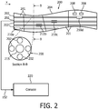
FIG. 2 is a block diagram showing an interventional instrument having sensing optical fibers and a parameter measuring fiber in accordance with the present principles; -
FIG. 3 is a block diagram showing an interventional instrument having sensing optical fibers and a parameter measuring fiber with windows opened to the external environment in accordance with the present principles; -
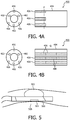
FIG. 4A is a diagram showing fiber sensors aligned to measure a parameter at a same location in accordance with the present principles; -
FIG. 4B is a diagram showing fiber sensors staggered to measure several parameters at a same location in accordance with the present principles; -
FIG. 5 is a diagram showing a stabilization device employed with optical sensors in accordance with one illustrative application; and -
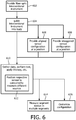
FIG. 6 is a flow diagram showing an illustrative interventional procedure in accordance with the present principles. - In many interventional procedures employing the use of guide wires or catheters, there is a need for compact and robust multipoint or distributed sensing of physiological motion characteristics and parameters including temperature, pressure, voltage changes, etc. In accordance with the present principles, Fiber-optic Bragg Gratings (FBG) can be incorporated directly into the body of an elongated instrument such as a guide wire or catheter without significantly changing the instrument mechanical properties, form factor or footprint. In addition, rapid multipoint and multiparameter measurements of segmental motion, voltage, temperature, and pressure are possible with the introduction of coatings or crystal materials (e.g., Bi12TiO20 crystals for voltage sensing, Ni-Mn-Ga memory shape metal alloys for magnetic sensing, Zn metal vapor deposition for enhanced temperature sensing, etc.).
- A FBG functionalized medical device such as a guide wire, catheter, or other flexible elongated instrument is described that performs simultaneous measurements of motion, voltage, temperature, pressure or other parameters in a distributed fashion such as at an "effector" segment or other segment of the instrument, e.g., the distal 10 cm segment including the tip of a loop/lasso mapping catheter used in electrophysiology procedures. Segmental motion tracking may be performed along the length of the instrument and therefore motion compensation / gating of instrument imaging data or voltage/temperature/pressure measurements may be made more accurate. Tracking deformation of the "effector" segment of the instrument may be employed to measure a change in biological tissue response to the intervention, e.g., monitoring tissue-induced FBG strains in a loop catheter to estimate electromechanical synchrony or to estimate intervention impact on cardiac contractility.
- It should be understood that the present invention will be described in terms of medical instruments; however, the teachings of the present invention are much broader and are applicable to any instruments employed in tracking or analyzing complex biological or mechanical systems. It should also be understood that the illustrative example of the optical device may also include electronic components, depending on the application. The elements depicted in the FIGS. may be implemented in various combinations of hardware and provide functions which may be combined in a single element or multiple elements.
- The functions of the various elements shown in the figures can be provided through the use of dedicated hardware as well as hardware capable of executing software in association with appropriate software. When provided by a processor, the functions can be provided by a single dedicated processor, by a single shared processor, or by a plurality of individual processors, some of which can be shared. Moreover, explicit use of the term "processor" or "controller" should not be construed to refer exclusively to hardware capable of executing software, and can implicitly include, without limitation, digital signal processor ("DSP") hardware, read-only memory ("ROM") for storing software, random access memory ("RAM"), and non-volatile storage.
- Moreover, all statements herein reciting principles, aspects, and embodiments of the invention, as well as specific examples thereof, are intended to encompass both structural and functional equivalents thereof. Additionally, it is intended that such equivalents include both currently known equivalents as well as equivalents developed in the future (i.e., any elements developed that perform the same function, regardless of structure).
- Thus, for example, it will be appreciated by those skilled in the art that the block diagrams presented herein represent conceptual views of illustrative system components and/or circuitry embodying the principles of the invention. Similarly, it will be appreciated that any flow charts, flow diagrams, state transition diagrams, pseudocode, and the like represent various processes which may be substantially represented in computer readable storage media and so executed by a computer or processor, whether or not such computer or processor is explicitly shown.
- Furthermore, embodiments of the present invention can take the form of a computer program product accessible from a computer-usable or computer-readable medium providing program code for use by or in connection with a computer or any instruction execution system. For the purposes of this description, a computer-usable or computer readable medium can be any apparatus that may include, store, communicate, propagate, or transport the program for use by or in connection with the instruction execution system, apparatus, or device. The medium can be an electronic, magnetic, optical, electromagnetic, infrared, or semiconductor system (or apparatus or device) or a propagation medium. Examples of a computer-readable medium include a semiconductor or solid state memory, magnetic tape, a removable computer diskette, a random access memory (RAM), a read-only memory (ROM), a rigid magnetic disk and an optical disk. Current examples of optical disks include compact disk - read only memory (CD-ROM), compact disk - read/write (CD-R/W) and DVD.
- Referring now to the drawings in which like numerals represent the same or similar elements and initially to
FIG. 1 , an optically functionalizedmedical device 100 is illustratively shown in accordance with one embodiment.Device 100 may include a guide wire, catheter, or other flexible elongated instrument that permits any or all of simultaneous measurements, segmental motion tracking and/or tracking deformation. - Simultaneous measurements maybe made using
device 100 for motion, voltage, temperature, pressure, color, strain, magnetism, position, biochemical state, etc. in a distributed fashion. For example, multiple measurements may be made at an effector segment or anysegment 101 of an instrument. The effector segment may include a distal end segment including a tip of a loop/lasso mapping catheter used in electrophysiology procedures, and more particularly, a distal end 10 cm segment.Device 100 is also capable of segmental motion tracking along the length of the instrument itself. Therefore, FBG-derived compensation and correction of instrument imaging data or voltage/temperature/pressure measurements can be made at one ormore segments 101. Thedevice 100 may also track deformation of the effector segment of the instrument to measure a change in biological tissue responsive to an intervention procedure, e.g., monitoring tissue-induced FBG strains in a loop catheter to estimate electromechanical synchrony or to estimate intervention impact on cardiac contractility. In this way, deflection experienced bydevice 100 may be correlated to deformations of tissue surrounding thedevice 100. - The
device 100 includes strain or other sensors 102 which are disposed over an elongated section of thedevice 100. One sensor 102 may be provided in each of threefibers 104 to form a sensor triplet at a given cross-section or axial location (x-direction) in this embodiment. Other numbers of fibers may also be employed. Thedevice 100 is preferably an elongated medical instrument for diagnosis, intervention, or therapy monitoring and may take the form of a catheter, guidewire, endoscope, etc. (with manual or automatic steering control for device navigation). Thefibers 104 are introduced into the body of theinstrument 100 with a series of fiber Bragg gratings or other sensors 102 spatially distributed along its length and/or clustered in functional regions of the instrument, e.g., a distal segment including a tip. The sensors 102 may form an array to collect data over a region. Eachfiber 104 may include one or more sensors 102. - The sensors 102 may include uncoated FBGs for shape sensing, FBGs incorporating materials for temperature sensing (e.g. Zn metal vapor deposition), FBGs incorporating materials for voltage / magnetic field sensing (e.g. Bi12TiO20, Ni-Mn-Ga), and/or other FBGs incorporating materials for sensitivity to other biophysical parameters of interest (e.g., pH sensing, pCO2, etc.). Other optical or electronic sensors may also be employed.
-
Device 100 may include anoptical module 110 for sense fiber illumination and receiving fiber signals. The source ofmodule 110 may be at a proximate end portion of the device and carry light using a waveguide or at the distal end portion for direct illumination. Themodule 110 includes a receiver function. -
Device 100 may be implemented as part of asystem 150 of components. Anoptical interrogation console 112 may be employed for readout of multiplexed signals returning from FBGs in all fibers. Acomputing device 114 may include a real-timeFBG sensing program 116 for sensing fiber shape, mapping temperature-sensitive FBG wavelength shifts into temperature changes, mapping voltage / magnetic field sensitive FBG wavelength shifts into voltage / magnetic field characteristics, and/or mapping other custom FBG wavelength shifts into corresponding biophysical parameter measurements. Theconsole 112 is configured for real-time interaction and visual display of instrument location and spatially distributed measurements (e.g., FBG-derived biophysical measurements, endoscope-based video or other imaging data, catheter-based video or other imaging data). - The
device 100 may optionally include low-costconventional sensors 120, e.g., electrodes for voltage sensing or may include a stabilizing /fixation mechanism 122 for holding a point on the sensing fiber fixed against a reference location of interest (e.g. a balloon with or without perforations to allow for flow past the fixation point). - The
system 150 may optionally include amedical imaging system 130 to provide a more global visualization of the anatomy of interest and interventional field-of-view (e.g., CV-X-ray system for cardiac procedures, or ultrasound system for body interventions, etc.). Theinstrument 100 maybe employed in conjunction with imaging data acquired either pre-procedurally, intra-procedurally, or simultaneously with optical interrogation. Imaging and optical data recordings can be used in combination to improve the estimates of biophysical parameters, instrument characteristics, and tissue properties to make decisions about interventional procedure guidance and monitor therapy progress. -
System 150 includes adata connection 152 to/from a sensor output (or FBG interrogation output) fromsensors 102a-c providing a read-out of fiber shape/additional biophysical parameters. The instrument data acquired may be carried onconnection 152, e.g., real-time video (e.g., from a video endoscope), real-time ultrasound (e.g., from an intracardiac echo, ICE catheter). Aninstrument therapy mechanism 154 delivers, e.g., RF power for an RF ablation catheter, ultrasound (US) power delivery for a HIFU instrument, etc. Thedata connection 152 between the FBG-enabledinstrument 100 also provide information to/from themedical imaging system 130. Feedback and control signals may be exchanged throughconnection 152. For example, instrument navigation may be employed as feedback based on FBG interrogation to assist in guiding theinstrument 100. In addition, feedback or control signals may be employed for instrument therapy delivery based on FBG interrogation. -
System 150 may include multiple processing orcomputing devices 114 for generating control signals, performing computations, generating video images, interpreting feedback, etc. For example, processing of distributed FBG shape measurements permits segment dependent respiratory, cardiac, or gross patient motion gating, correction of instruments, medical imaging system data, etc. In particularly useful embodiments, from onesegment 101 of a sensing fiber, cardiac motion may dominate atsensor 102c, in yet anothersegment 101, respiratory motion may dominate atsensor 102b, whereas athird segment 101 reflects gross patient motion atsensor 102a. Multiple fibers (or even a single fiber) permit feedback from all three segments. A user, such as a surgeon or technician, can select specific segments from which to extract gating signals via graphical interaction on aninstrument console 112 ofsystem 150. The signals from these regions can then be used to gate or motion correct the actual measurements of interest to obtain motion-compensation video from a video endoscope, or motion-compensated ultrasound from an ICE catheter, or motion-corrected fluoroscopy from an X-ray imaging system, etc. In addition, processing of FBG shape measurements may be performed byprocessor 114 to track deformation of the "effector" segment of theinstrument 100 and so monitor a change resulting from intervention, e.g., monitoring tissue-induced FBG strains in a loop catheter to estimate electromechanical synchrony or to estimate intervention impact on cardiac contractility. - The user may store data in
memory 115. Memory may include programs (e.g., program 116). Theprogram 116 may be adapted to take measurements and control sensors (e.g., FBGs). Adisplay 157 may be provided for visualizing procedures and/or for interfacing with theconsole 112 anddevice 100 during a procedure. The user may employ auser interface 159 to interact with theconsole 112 and/or theinstrument 100. Theinterface 159 may include a keyboard, a mouse, a touch screen system, etc. - Referring to
FIG. 2 , an illustrative interventionalmedical device 200 includes a shape sensing fiber(s) 202 in an elongatedmedical instrument 204 with segment specific motion correction forindividual segments 201 or thedevice 200 as a whole. In this embodiment, theelongated instrument 204 may include low-cost sensors 208 such as electrodes for voltage mapping, miniature thermistors for temperature sensing, etc. In addition, thesensing fibers 202 include a distribution ofFBGs 210a-c embedded within the instrument body. During a procedure, FBG-derived shape/motion data are visualized on a graphical display (157,FIG. 1 ) with instrument location shown as a registered overlay on top of pre-procedurally acquired imaging data or intra-procedurally acquired imaging data from a medical imaging system sharing a data connection with the FBG-enabled instrument. A clinician is enabled to graphically select the segments or sub-segments of theinstrument 200 to be used for separate respiratory motion gating (and/or compensation) 210a, cardiac motion gating (and/or compensation) 210b, gastro-intestinal (GI) motion (and/or compensation) 210c, and gross patient motion (and/or compensation) 210d, for example. The sensor positions and locations can be predetermined or adjusted to provide spatially specific measurements concurrently from different information sources. - A workstation or
console 220 takes the prescribed motion/gating signals from each of the segments or sub-segments, then computes and displays, in real-time, the motion corrected measurements of interest, e.g., gated/motion-corrected voltage measurements from an EP mapping catheter. Position tracking provided by the embeddedsensing fiber 202 permits for spatial mapping and multidimensional reconstruction of data acquired by theinstrument 200, e.g., video/image mapping/surface reconstruction in 3D, voltage / temperature mapping in 3D, etc. Furthermore, deformation measurements from thesensing fiber 202 can be combined with conventional instrument measurements (208) to monitor responses to the intervention. For example, a shape-sensing-enabled flexible loop catheter with conventional electrodes (208) for both voltage measurement and delivery of ablation energy can be positioned in contact with the ventricular wall during ablation and voltage measurement. Changes in deformation of the loop segment in contact with wall will reflect changes in synchrony and magnitude of myocardial motion, which is of clinical relevance in assessing response. - The workstation or
console 220 can also take the position / motion signals from each of the segments or sub-segment to display, in real-time, a fused overlay of the FBG-enabled interventional device with imaging data acquired concurrently or pre-procedurally. This allows for visualization of the interventional device via FBG enabled position sensing which is especially useful for imaging modalities that do not permit direct visualization of the device itself. For example, standard catheters are poorly visible under ultrasound imaging or are completely invisible under magnetic resonance imaging. The use of FBG-enabled instrumentation in combination with imaging would facilitate intervention guidance since the imaging modality would provide feedback about tissue/organ properties whereas FBG sensing would provide information about instrument properties. - It should be understood that the instruments described herein may have many functional features and variations. For example, the instruments (100, 200, etc.) may include a working channel or
lumen 215 to provide a way to by-pass fluids, to apply suction, to permit the movement of other tools and instruments, etc. - Referring to
FIG. 3 , an illustrative interventionalmedical device 300 includes one or moreshape sensing fibers 302 each with a single biophysical parameter sensing core and a contact/window 306 to anexternal environment 307. Theelongated instrument 304 has FBG-based sensors for measurement of temperature, voltage, magnetic field, chemical concentration, etc. to achieve further miniaturization potential. For the measurement of scalar fields such as temperature or voltage, a single optical fiber with a distribution of FBGs spaced along the length of interest (depending on the application) is employed. For multiparameter sensing in the illustrative example, the coatings used for consecutive FBGs can be interleaved so that a temperaturesensitive FBG 308 is positioned beside a voltagesensitive FBG 310, followed by a pressuresensitive FBG 312 in an alternating pattern. The pattern and distribution/spacing of these FBGs can be varied according to the instrument type and application. - Given the close proximity of each of these FBG types and a sensor 311 of the additional
shape sensing fiber 302 embedded within theinstrument 300, it is also possible to apply the measured strains from the shape sensing fibers to obtain deformation-corrected temperature, pressure, or voltage measurements. The measured biophysical parameters such as temperature are used to obtain corrected estimates for fiber shape (since wavelength shifts in FBGs are strain as well as temperature sensitive). In this way, accurate and relevant multiparameter measurements can be made to adjust and further provide information during an interventional procedure. - To ensure that the biophysical parameter FBGs are able to sense environmental conditions, an embodiment in which the biophysical parameter sensing fiber 302' is eccentrically positioned close to the outer perimeter of the
instrument 300 is shown. For temperature or voltage sensitized FBGs, a metallic orconductive ring 314 is placed around theinstrument 300 in contact with both theFBG temperature sensor 308 and the external environment to ensure coupling. For pressure-sensitizedFBGs 310,windows windows windows - Referring to
FIGS. 4A and 4B , an illustrative interventionalmedical device 400 is shown in cross-section on the left and with an illustrative side diagram on the right to demonstrate the present concepts. Thedevice 400 includesshape sensing fibers 402 in an elongatedmedical instrument 404 with multiple biophysical parameter sensing cores orsensors 406 which may include contacts or windows to an external environment to make measurements thereof. Aligned multiparameter sensing cores are depicted inFIG. 4A , whileFIG. 4B shows staggered multiparameter sensing cores or sensors. - Multi-core arrangements of biophysical parameter sensing fibers or
sensors 406 can be positioned around theshape sensing fibers 402 to permit for parameter sensing at multiple points around the instrument periphery. If the FBGs in these cores are aligned (as inFIG. 4A ) so that each FBG at the same axial section (at position P) senses the same biophysical parameter, e.g. temperature, the measurements can be averaged to obtain higher signal to noise (SNR) performance. - Alternatively, the cores or
sensors 406 can be staggered (as depicted inFIG. 4B ) so that at the same axial contact point (Q), each of the FBGs senses a different biophysical parameter, allowing for multi-parameter sensing at the same location along theinstrument 400. As inFIGS. 1-3 , these multi-parameter measurements can be used jointly to derive more accurate temperature, strain, etc. corrected estimates. It should be understood that many variations of the described embodiments may exist. Different features and different parameters may be configured for a given procedure or application. In some embodiments, the elongated instrument may be reconfigurable to permit customization of the positioning of FBG sensors or even the fiber density or position relative the periphery or other feature of the instrument. It should also be understood that optical fibers may be replaced with other signals carrying devices and that optical sensors may include non-optical sensors. - Referring to
FIG. 5 , additional mechanisms or features may be employed to customize or increase the functionality of the instruments in accordance with the present principles. Any of the described embodiments may be employed together with a stabilization/mechanical fixation device 502 (e.g., based on balloons or other mechanical structures) for an instrument 500 (similar to those described asinstruments sensitive FBG 504 at ananatomical location 506 desired for reference temperature measurements far from a site of ablation therapy. - Another mechanism that may be employed using FBGs includes a feedback mechanism employed for feedback or control of navigation or therapy delivery based on multi-sensor distributed measurements (e.g., a temperature reference at a fixed point distant from an ablation site for monitoring and control of temperature elevation following energy delivery). The information collected at the site is employed to provide information to the technician or surgeon to provide feedback on events occurring at the site (e.g., 506). The
system 150 depicted inFIG. 1 , e.g., maybe employed for collecting and using the feedback during a procedure. - For example, sensors (optical or non-optical) are preferably distributed such that deformation, vibration, or any other distortion mode induced in a segment of the instrument is measured to determine either a tissue response to the instrument during an interventional procedure, or feedback from the instrument about tissue-instrument interaction (e.g., haptic feedback during instrument navigation within a lumen).
- Referring to
FIG. 6 , a medical interventional method or procedure is illustratively depicted. Inblock 602, an interventional instrument is provided including an elongated flexible member having one or more sections, which may be segmented and disposed longitudinally. At least one optical fiber is disposed internally in the flexible member, and a plurality of optical sensors are coupled to the at least one optical fiber and distributed along a length of the flexible member such that the optical sensors are positioned to monitor separate parameters simultaneously along the flexible member to provide distributed sensing. Inblock 604, the interventional instrument is guided into a body to perform a medical procedure. Inblock 606, in one optional embodiment, a set of optical sensors associated with a plurality of optical fibers is aligned where an aligned set includes a sensor associated with each fiber such that the aligned set measures a same parameter at a same axial position along a length of the flexible member. Inblock 608, in another optional embodiment, a set of optical sensors associated with the plurality of optical fibers is staggered where a staggered set includes a sensor associated with each fiber such that the staggered set measures different parameters at a same axial position along a length of the flexible member. - An array of sensors maybe employed to map, monitor, apply therapy, etc. to a given area. In
block 610, data is concurrently gathered from a plurality of data sources by respective sensors. Testing or therapy is performed, or any other action is performed using the fiber optic interventional instrument. In one embodiment, respective sensors are positioned relatively, the relative position being determined to provide proximity to different data sources when the flexible member is located in a data gathering position inblock 612. Inblock 614, segmental motion of two or more of the segments is measured to provide a more accurate positional orientation for the instrument. In another embodiment, deformation of a segment of the instrument is measured using distributed sensors to determine a tissue response to the instrument during an interventional procedure. Inblock 616, fibers and sensor arrays may be customized and repositioned to provide a flexible design to accommodate a given procedure. - The present principles provide systems and methods for performing clinical, surgical or testing applications using fiber optic technology in medical instrumentation. Clinical applications include, but are not limited to catheter-based navigation, mapping, and ablation for treatment of atrial fibrillation or ventricular arrhythmias (FBG-functionalized ablation catheter, pulmonary vein loop catheter, coronary sinus catheter, etc.), pulmonary venous contraction monitoring, cardiac resynchronization therapy and cardiac contractility / electromechanical synchrony assessment, cardiac filter device or balloon deployment, transcatheter valve replacement, and FBG-enabled endoscopy-based procedures (imaging, biopsy, ablation, NOTES, etc.) in cardiac, pulmonary, or body interventions. Other applications and procedures where the present principles are applicable also exist and are contemplated by the present embodiments.
- In interpreting the appended claims, it should be understood that:
- a) the word "comprising" does not exclude the presence of other elements or acts than those listed in a given claim;
- b) the word "a" or "an" preceding an element does not exclude the presence of a plurality of such elements;
- c) any reference signs in the claims do not limit their scope;
- d) several "means" may be represented by the same item or hardware or software implemented structure or function; and
- e) no specific sequence of acts is intended to be required unless specifically indicated.
- Having described preferred embodiments for systems and methods for optical sensing - enabled interventional instruments for rapid distributed measurements of biophysical parameters (which are intended to be illustrative and not limiting), it is noted that modifications and variations can be made by persons skilled in the art in light of the above teachings. It is therefore to be understood that changes may be made in the particular embodiments of the disclosure disclosed which are within the scope of the embodiments disclosed herein as outlined by the appended claims. Having thus described the details and particularity required by the patent laws, what is claimed and desired protected by Letters Patent is set forth in the appended claims.
Claims (13)
- An interventional instrument, comprising:an elongated flexible member (100);at least one shape sensing fiber (104, 302) disposed internally in the flexible member; anda plurality of pressure sensors (310) coupled to the at least one shape sensing fiber and distributed along a length of the flexible member such that the pressure sensors are positioned to monitor pressure simultaneously at different positions along the flexible member to provide distributed pressure sensing.
- The instrument as recited in claim 1, wherein each of the plurality of pressure sensors includes a pressure-sensitized fiber Bragg grating.
- The instrument as recited in claim 1, wherein the at least one shape sensing fiber (104, 302) includes a plurality of fiber Bragg gratings of which strain is arranged to be measured, wherein measurement of strains from the plurality of fiber Bragg grating allows reconstruction of the shape of the at least one shape sensing fiber.
- The instrument as recited in claim 2, further comprising a window (306) at or near the fiber Bragg grating for exposure of the fiber Bragg grating to pressure conditions in the external environment.
- The instrument as recited in claim 1, wherein the elongated flexible member (100) includes one of a guide wire, a catheter and an endoscopic tool.
- The instrument as recited in claim 1, wherein the at least one shape sensing fiber (104, 302) includes a plurality of optical fibers distributed within the flexible member.
- The instrument as recited in claim 1, wherein the instrument is employed in conjunction with imaging data (130) acquired pre-procedurally, intra-procedurally, or simultaneously with optical interrogation.
- The instrument as recited in claim 1, wherein the flexible member includes a closeable aperture to expose at least one of the plurality of pressure sensors.
- A system for an interventional procedure, comprising:an interventional instrument (100, 300) as recited in claim 1; anda workstation (112) configured to provide an interface (159) to control the interventional instrument and to perform a procedure using the interventional instrument.
- The system as recited in claim 9, further comprising a position/shape tracking system (112, 116) for tracking the instrument during an interventional procedure wherein the workstation includes a display such that position data collected from the instrument is overlaid on image data.
- The system as recited in claim 9, further comprising a therapy mechanism (154) disposed on the instrument and controlled using the workstation such that therapy is applied to tissue during an interventional procedure.
- The system as recited in claim 9, further comprising a fixation mechanism (122) disposed on the instrument and controlled using the workstation such that activation of the fixation mechanism stabilizes or positions at least one of the sensors relative to a target location during an interventional procedure.
- The instrument as recited in claim 9, wherein the instrument is employed in conjunction with imaging data (130) acquired pre-procedurally, intra-procedurally, or simultaneously with optical interrogation.
Applications Claiming Priority (2)
| Application Number | Priority Date | Filing Date | Title |
|---|---|---|---|
| US25431709P | 2009-10-23 | 2009-10-23 | |
| EP10760016A EP2490612A1 (en) | 2009-10-23 | 2010-08-26 | Optical sensing - enabled interventional instruments for rapid distributed measurements of biophysical parameters |
Related Parent Applications (1)
| Application Number | Title | Priority Date | Filing Date |
|---|---|---|---|
| EP10760016A Division EP2490612A1 (en) | 2009-10-23 | 2010-08-26 | Optical sensing - enabled interventional instruments for rapid distributed measurements of biophysical parameters |
Publications (1)
| Publication Number | Publication Date |
|---|---|
| EP3266383A1 true EP3266383A1 (en) | 2018-01-10 |
Family
ID=43063556
Family Applications (2)
| Application Number | Title | Priority Date | Filing Date |
|---|---|---|---|
| EP10760016A Withdrawn EP2490612A1 (en) | 2009-10-23 | 2010-08-26 | Optical sensing - enabled interventional instruments for rapid distributed measurements of biophysical parameters |
| EP17183272.8A Withdrawn EP3266383A1 (en) | 2009-10-23 | 2010-08-26 | Optical sensing - enabled interventional instruments for rapid distributed measurements of pressure |
Family Applications Before (1)
| Application Number | Title | Priority Date | Filing Date |
|---|---|---|---|
| EP10760016A Withdrawn EP2490612A1 (en) | 2009-10-23 | 2010-08-26 | Optical sensing - enabled interventional instruments for rapid distributed measurements of biophysical parameters |
Country Status (6)
| Country | Link |
|---|---|
| US (1) | US10610085B2 (en) |
| EP (2) | EP2490612A1 (en) |
| JP (2) | JP5952736B2 (en) |
| CN (1) | CN102573691B (en) |
| RU (1) | RU2577509C2 (en) |
| WO (1) | WO2011048509A1 (en) |
Cited By (3)
| Publication number | Priority date | Publication date | Assignee | Title |
|---|---|---|---|---|
| WO2023177889A1 (en) * | 2022-03-17 | 2023-09-21 | Bard Access Systems, Inc. | Fiber optic medical systems and devices with atraumatic tip |
| US11899249B2 (en) | 2020-10-13 | 2024-02-13 | Bard Access Systems, Inc. | Disinfecting covers for functional connectors of medical devices and methods thereof |
| US11931179B2 (en) | 2020-03-30 | 2024-03-19 | Bard Access Systems, Inc. | Optical and electrical diagnostic systems and methods thereof |
Families Citing this family (48)
| Publication number | Priority date | Publication date | Assignee | Title |
|---|---|---|---|---|
| JP6072017B2 (en) * | 2011-06-10 | 2017-02-01 | コーニンクレッカ フィリップス エヌ ヴェKoninklijke Philips N.V. | Dynamic constraints associated with optical shape sensing |
| DE102011081546B4 (en) * | 2011-08-25 | 2013-07-04 | Siemens Ag | Apparatus and method for minimally invasive length measurement within a hollow organ |
| JP5618422B2 (en) * | 2011-09-02 | 2014-11-05 | 飛島建設株式会社 | FBG optical fiber sensor type strain sensor |
| CN103765176B (en) * | 2011-09-02 | 2016-08-17 | 皇家飞利浦有限公司 | The Medical Equipment using distributed fiber optic temperature sensing inserts and exits information |
| WO2013061280A1 (en) * | 2011-10-28 | 2013-05-02 | Hemodynamix Medical Systems Inc. | Fluid temperature and flow sensor apparatus and system for cardiovascular and other medical applications |
| US10463259B2 (en) * | 2011-10-28 | 2019-11-05 | Three Rivers Cardiovascular Systems Inc. | System and apparatus comprising a multi-sensor catheter for right heart and pulmonary artery catheterization |
| EP2779897B1 (en) * | 2011-11-16 | 2019-07-31 | Commonwealth Scientific and Industrial Research Organisation | An optical sensing device |
| JP5462424B1 (en) * | 2012-03-22 | 2014-04-02 | オリンパスメディカルシステムズ株式会社 | Measurement probe, bio-optical measurement apparatus, and bio-optical measurement system |
| EP2830482A1 (en) * | 2012-03-29 | 2015-02-04 | Koninklijke Philips N.V. | Temperature control mechanisms for stable shape sensing |
| US20130274618A1 (en) * | 2012-04-17 | 2013-10-17 | Boston Scientific Scimed, Inc. | Guidewire system for use in transcatheter aortic valve implantation procedures |
| US10506934B2 (en) * | 2012-05-25 | 2019-12-17 | Phyzhon Health Inc. | Optical fiber pressure sensor |
| JP2015522324A (en) * | 2012-06-08 | 2015-08-06 | コーニンクレッカ フィリップス エヌ ヴェ | Distributed sensing device that scales physiological features |
| WO2014024069A1 (en) * | 2012-08-04 | 2014-02-13 | Koninklijke Philips N.V. | Quantifying probe deflection for improved catheter identification |
| EP2879752B1 (en) | 2012-08-14 | 2021-10-06 | Intuitive Surgical Operations, Inc. | Systems and methods for configuring components in a minimally invasive instrument |
| CN108403088A (en) * | 2012-10-02 | 2018-08-17 | 皇家飞利浦有限公司 | It is mapped using the volume of optic shape sensor |
| WO2014091340A1 (en) | 2012-12-14 | 2014-06-19 | Koninklijke Philips N.V. | Wrist-worn device for sensing ambient light intensity |
| CA2895332A1 (en) * | 2012-12-21 | 2014-06-26 | David Anderson | Multi-sensor devices |
| US20140180168A1 (en) * | 2012-12-21 | 2014-06-26 | Volcano Corporation | Guidewire with touch sensor |
| CN105073172B (en) * | 2013-02-14 | 2019-12-10 | 皇家飞利浦有限公司 | interventional system |
| CN105120789B (en) * | 2013-03-26 | 2019-12-31 | 皇家飞利浦有限公司 | System and method for minimizing distortion for optical shape sensing enabled instruments |
| CN109199388B (en) * | 2013-07-29 | 2022-03-18 | 直观外科手术操作公司 | Shape sensor system with redundant sensing |
| CN105517489B (en) * | 2013-09-06 | 2020-06-05 | 皇家飞利浦有限公司 | Navigation system |
| WO2015051003A1 (en) | 2013-10-04 | 2015-04-09 | Vascular Imaging Corporation | Imaging techniques using an imaging guidewire |
| WO2015059969A1 (en) | 2013-10-25 | 2015-04-30 | ニューブレクス株式会社 | Fiber optic biodiagnostic sensor system and vascular insertion type device for measuring pressure distribution |
| US10537255B2 (en) | 2013-11-21 | 2020-01-21 | Phyzhon Health Inc. | Optical fiber pressure sensor |
| JP6188564B2 (en) * | 2013-12-19 | 2017-08-30 | オリンパス株式会社 | Insertion device |
| JP2015134001A (en) * | 2014-01-16 | 2015-07-27 | ニプロ株式会社 | Measurement device using optical fiber |
| US10322299B2 (en) | 2014-02-27 | 2019-06-18 | Koninklijke Philips N.V. | System for performing a therapeutic procedure |
| JP6659560B2 (en) * | 2014-02-27 | 2020-03-04 | コーニンクレッカ フィリップス エヌ ヴェKoninklijke Philips N.V. | Registration device for intervention procedure and its operation method |
| WO2015152999A1 (en) * | 2014-03-31 | 2015-10-08 | Regents Of The University Of Minnesota | Navigation tools using shape sensing technology |
| CN106659394A (en) | 2014-07-13 | 2017-05-10 | 三河城心血管系统有限公司 | System and apparatus comprising multisensor guidewire for use in interventional cardiology |
| WO2016070110A1 (en) * | 2014-10-31 | 2016-05-06 | Lake Region Medical, Inc. | Fiber bragg grating multi-point pressure sensing guidewire with birefringent component |
| WO2016070099A1 (en) * | 2014-10-31 | 2016-05-06 | Lake Region Medical, Inc. | Membrane-free fiber bragg grating pressure sensing guidewire |
| JP6618254B2 (en) * | 2014-12-24 | 2019-12-11 | 日本ライフライン株式会社 | Temperature measuring device and catheter system |
| US10499995B2 (en) * | 2015-02-02 | 2019-12-10 | Louis FERREIRA | Navigation by bending forces |
| US11272847B2 (en) | 2016-10-14 | 2022-03-15 | Hemocath Ltd. | System and apparatus comprising a multi-sensor catheter for right heart and pulmonary artery catheterization |
| CN115363537A (en) * | 2016-12-09 | 2022-11-22 | 直观外科手术操作公司 | System and method for distributed heat flux sensing of body tissue |
| CN110225710B (en) * | 2017-02-01 | 2022-12-30 | 直观外科手术操作公司 | System and method for registration of image-guided procedures |
| US20190380762A1 (en) * | 2017-02-21 | 2019-12-19 | St. Jude Medical, Cardiology Division, Inc. | Blood Vessel Isolation Ablation Device |
| EP3524953A1 (en) * | 2018-02-07 | 2019-08-14 | Koninklijke Philips N.V. | Distributed intravascular fiber bragg pressure sensor |
| US11801362B2 (en) * | 2018-05-21 | 2023-10-31 | The Texas A&M University System | Surgical cannulas and related methods |
| RU2760994C2 (en) * | 2018-08-01 | 2021-12-02 | Юрий Викторович Бабченко | Device for measuring heart work parameters |
| CN112804946A (en) * | 2018-08-07 | 2021-05-14 | 奥瑞斯健康公司 | Combining strain-based shape sensing with catheter control |
| CN109223060A (en) * | 2018-08-23 | 2019-01-18 | 荆门市第二人民医院 | The control system and control method of auxiliary device in a kind of surgical operation |
| US11134851B2 (en) * | 2018-12-14 | 2021-10-05 | Viavi Solutions Inc. | Sensor device |
| GB2580164A (en) * | 2018-12-21 | 2020-07-15 | Imperial College Sci Tech & Medicine | A sensor |
| CN111839442B (en) * | 2020-06-08 | 2021-09-07 | 北京交通大学 | Fiber grating sensor and flexible ureteroscope |
| CN112237423A (en) * | 2020-08-13 | 2021-01-19 | 张海军 | Intervention type weak magnetic and pressure sensing system |
Citations (6)
| Publication number | Priority date | Publication date | Assignee | Title |
|---|---|---|---|---|
| WO2001013060A1 (en) * | 1999-08-13 | 2001-02-22 | Advanced Sensor Technologies Llc | Probe position sensing system for use in a coordinate measuring machine |
| WO2001074252A2 (en) * | 2000-03-31 | 2001-10-11 | Rita Medical Systems Inc. | Tissue biopsy and treatment apparatus and method |
| US20040165810A1 (en) * | 2003-02-20 | 2004-08-26 | Fuji Photo Optical Co., Ltd. | Device for detecting three-dimensional shapes of elongated flexible body |
| WO2007015139A2 (en) * | 2005-08-01 | 2007-02-08 | Endosense Sa | Medical apparatus system having optical fiber load sensing capability |
| CN101099657A (en) * | 2007-07-13 | 2008-01-09 | 上海大学 | Thin long flexible rod spatial shape detecting device and method |
| JP2008173397A (en) * | 2007-01-22 | 2008-07-31 | Olympus Corp | Endoscope system |
Family Cites Families (35)
| Publication number | Priority date | Publication date | Assignee | Title |
|---|---|---|---|---|
| JPS6260571A (en) * | 1985-09-12 | 1987-03-17 | アロカ株式会社 | Fiber applicator for endoscopic treatment |
| CA2034285A1 (en) * | 1990-02-09 | 1991-08-10 | Masao Yafuso | Method and system for monitoring of blood constituents in vivo |
| US5124130A (en) | 1990-05-22 | 1992-06-23 | Optex Biomedical, Inc. | Optical probe |
| JPH07270261A (en) | 1994-03-31 | 1995-10-20 | Olympus Optical Co Ltd | Contact force and tactile sensor using piezoelectric vibration having three-terminal structure |
| US5493113A (en) * | 1994-11-29 | 1996-02-20 | United Technologies Corporation | Highly sensitive optical fiber cavity coating removal detection |
| JP3507161B2 (en) | 1994-12-28 | 2004-03-15 | テルモ株式会社 | Blood analyte measuring device |
| RU2116044C1 (en) * | 1996-04-02 | 1998-07-27 | Геннадий Борисович Яцевич | Panoramic light fiberscope |
| US6120457A (en) * | 1997-07-02 | 2000-09-19 | Johnson & Johnson Professional, Inc. | In vivo zeroing of catheter pressure sensor |
| US6256090B1 (en) | 1997-07-31 | 2001-07-03 | University Of Maryland | Method and apparatus for determining the shape of a flexible body |
| EP1059878B1 (en) * | 1998-03-05 | 2005-11-09 | Gil M. Vardi | Optical-acoustic imaging device |
| US6285806B1 (en) | 1998-05-31 | 2001-09-04 | The United States Of America As Represented By The Secretary Of The Navy | Coherent reflectometric fiber Bragg grating sensor array |
| FR2785132B1 (en) * | 1998-10-27 | 2000-12-22 | Tokendo Sarl | DISTAL COLOR CCD SENSOR VIDEOENDOSCOPIC PROBE |
| GB0021976D0 (en) * | 2000-09-07 | 2000-10-25 | Optomed As | Multi-parameter fiber optic probes |
| US7194296B2 (en) * | 2000-10-31 | 2007-03-20 | Northern Digital Inc. | Flexible instrument with optical sensors |
| RU2208375C2 (en) * | 2001-07-17 | 2003-07-20 | Общество с ограниченной ответственностью "ЭФА-МВТ" | Videolaparoscope |
| US6748255B2 (en) | 2001-12-14 | 2004-06-08 | Biosense Webster, Inc. | Basket catheter with multiple location sensors |
| EP1501415A1 (en) | 2002-05-09 | 2005-02-02 | Given Imaging Ltd. | System and method for in vivo sensing |
| WO2004083909A2 (en) | 2003-03-19 | 2004-09-30 | Luna Innovations, Inc. | Fiber-optic apparatus and method for making simultaneous multiple parameter measurements |
| JP4594616B2 (en) * | 2003-12-19 | 2010-12-08 | オリンパス株式会社 | Capsule medical system |
| US8306592B2 (en) | 2003-12-19 | 2012-11-06 | Olympus Corporation | Capsule medical device |
| JP4520161B2 (en) * | 2004-01-08 | 2010-08-04 | オリンパス株式会社 | Capsule medical device |
| JP2006043449A (en) | 2004-07-08 | 2006-02-16 | Pentax Corp | Endoscope system |
| US20060013523A1 (en) | 2004-07-16 | 2006-01-19 | Luna Innovations Incorporated | Fiber optic position and shape sensing device and method relating thereto |
| US8121687B2 (en) * | 2004-11-01 | 2012-02-21 | Proteus Biomedical, Inc. | Cardiac motion characterization by strain measurement |
| US7528860B2 (en) | 2005-04-29 | 2009-05-05 | Hewlett-Packard Development Company, L.P. | Method and system for videoconferencing between parties at N sites |
| JP2007044412A (en) * | 2005-08-12 | 2007-02-22 | Pentax Corp | Endoscope insertion shape detecting probe |
| US7228017B2 (en) * | 2005-09-30 | 2007-06-05 | General Electric Company | Fiber optic sensing device and method of making and operating the same |
| TWI274225B (en) | 2005-11-11 | 2007-02-21 | Coretronic Corp | Projector and positioning structure for positioning the integration rod module in the projector |
| US7433552B2 (en) | 2005-12-22 | 2008-10-07 | Palo Alto Research Center Incorporated | Obtaining analyte information |
| JP5631585B2 (en) | 2006-03-22 | 2014-11-26 | コーニンクレッカ フィリップス エレクトロニクス エヌ.ヴィ. | Optical fiber equipment sensing system |
| JP4918288B2 (en) | 2006-06-02 | 2012-04-18 | オリンパス株式会社 | Endoscope device |
| WO2008049187A1 (en) * | 2006-10-25 | 2008-05-02 | Lxsix Photonics, Inc. | Tilted grating sensor |
| US20090076476A1 (en) * | 2007-08-15 | 2009-03-19 | Hansen Medical, Inc. | Systems and methods employing force sensing for mapping intra-body tissue |
| JP2011500162A (en) * | 2007-10-11 | 2011-01-06 | タフツ ユニバーシティー | System, apparatus, and method employing optical fiber shape tracking |
| US8780339B2 (en) | 2009-07-15 | 2014-07-15 | Koninklijke Philips N.V. | Fiber shape sensing systems and methods |
-
2010
- 2010-08-26 EP EP10760016A patent/EP2490612A1/en not_active Withdrawn
- 2010-08-26 US US13/501,101 patent/US10610085B2/en not_active Expired - Fee Related
- 2010-08-26 CN CN201080047765.0A patent/CN102573691B/en not_active Expired - Fee Related
- 2010-08-26 JP JP2012534795A patent/JP5952736B2/en not_active Expired - Fee Related
- 2010-08-26 RU RU2012121174/14A patent/RU2577509C2/en not_active IP Right Cessation
- 2010-08-26 WO PCT/IB2010/053845 patent/WO2011048509A1/en active Application Filing
- 2010-08-26 EP EP17183272.8A patent/EP3266383A1/en not_active Withdrawn
-
2015
- 2015-03-13 JP JP2015051145A patent/JP6157526B2/en not_active Expired - Fee Related
Patent Citations (6)
| Publication number | Priority date | Publication date | Assignee | Title |
|---|---|---|---|---|
| WO2001013060A1 (en) * | 1999-08-13 | 2001-02-22 | Advanced Sensor Technologies Llc | Probe position sensing system for use in a coordinate measuring machine |
| WO2001074252A2 (en) * | 2000-03-31 | 2001-10-11 | Rita Medical Systems Inc. | Tissue biopsy and treatment apparatus and method |
| US20040165810A1 (en) * | 2003-02-20 | 2004-08-26 | Fuji Photo Optical Co., Ltd. | Device for detecting three-dimensional shapes of elongated flexible body |
| WO2007015139A2 (en) * | 2005-08-01 | 2007-02-08 | Endosense Sa | Medical apparatus system having optical fiber load sensing capability |
| JP2008173397A (en) * | 2007-01-22 | 2008-07-31 | Olympus Corp | Endoscope system |
| CN101099657A (en) * | 2007-07-13 | 2008-01-09 | 上海大学 | Thin long flexible rod spatial shape detecting device and method |
Non-Patent Citations (2)
| Title |
|---|
| FERNANDEZ FERNANDEZ A ET AL: "Multi-component force sensor based on multiplexed fibre Bragg grating strain sensors; Multi-component force sensor based on multiplexed FBG strain sensors", MEASUREMENT SCIENCE AND TECHNOLOGY, IOP, BRISTOL, GB, vol. 12, no. 7, 1 July 2001 (2001-07-01), pages 810 - 813, XP020063206, ISSN: 0957-0233, DOI: 10.1088/0957-0233/12/7/310 * |
| LUNWEI ZHANG ET AL: "On SDM/WDM FBG Sensor Net for Shape Detection of Endoscope", MECHATRONICS AND AUTOMATION, 2005 IEEE INTERNATIONAL CONFERENCE NIAGARA FALLS, ON, CANADA JULY 29-AUG 1, 2005, PISCATAWAY, NJ, USA,IEEE, vol. 4, 29 July 2005 (2005-07-29), pages 1986 - 1991, XP010913579, ISBN: 978-0-7803-9044-7 * |
Cited By (3)
| Publication number | Priority date | Publication date | Assignee | Title |
|---|---|---|---|---|
| US11931179B2 (en) | 2020-03-30 | 2024-03-19 | Bard Access Systems, Inc. | Optical and electrical diagnostic systems and methods thereof |
| US11899249B2 (en) | 2020-10-13 | 2024-02-13 | Bard Access Systems, Inc. | Disinfecting covers for functional connectors of medical devices and methods thereof |
| WO2023177889A1 (en) * | 2022-03-17 | 2023-09-21 | Bard Access Systems, Inc. | Fiber optic medical systems and devices with atraumatic tip |
Also Published As
| Publication number | Publication date |
|---|---|
| US10610085B2 (en) | 2020-04-07 |
| CN102573691B (en) | 2016-02-24 |
| JP5952736B2 (en) | 2016-07-13 |
| CN102573691A (en) | 2012-07-11 |
| US20120197097A1 (en) | 2012-08-02 |
| WO2011048509A1 (en) | 2011-04-28 |
| JP2013508058A (en) | 2013-03-07 |
| JP6157526B2 (en) | 2017-07-05 |
| RU2012121174A (en) | 2013-11-27 |
| RU2577509C2 (en) | 2016-03-20 |
| EP2490612A1 (en) | 2012-08-29 |
| JP2015154938A (en) | 2015-08-27 |
Similar Documents
| Publication | Publication Date | Title |
|---|---|---|
| US10610085B2 (en) | Optical sensing-enabled interventional instruments for rapid distributed measurements of biophysical parameters | |
| EP2608720B1 (en) | Mapping system for medical procedures | |
| CN106999153B (en) | Automatic tracking and registration of ultrasound probes using optical shape sensing with distal tip not fixed | |
| US11547489B2 (en) | Shape sensing of multiple over-the-wire devices | |
| US20150141764A1 (en) | Distributed sensing device for referencing of physiological features | |
| US20130324833A1 (en) | Non-rigid-body morphing of vessel image using intravascular device shape | |
| JP2013534433A (en) | Optical fiber shape reconstruction | |
| WO2013030749A2 (en) | Medical device insertion and exit information using distributed fiber optic temperature sensing | |
| CN105828721B (en) | Robotic ultrasound for shape sensing for minimally invasive interventions | |
| US11432740B2 (en) | Introducer sheath localization and visualization | |
| US20140243687A1 (en) | Shape sensing devices for real-time mechanical function assessment of an internal organ | |
| JP2017500935A5 (en) | ||
| WO2021186330A1 (en) | System and method for optical sensor reference frame alignment | |
| US20240000515A1 (en) | System, Method, and Apparatus for Improved Confirm of an Anatomical Position of a Medical Instrument |
Legal Events
| Date | Code | Title | Description |
|---|---|---|---|
| PUAI | Public reference made under article 153(3) epc to a published international application that has entered the european phase |
Free format text: ORIGINAL CODE: 0009012 |
|
| AC | Divisional application: reference to earlier application |
Ref document number: 2490612 Country of ref document: EP Kind code of ref document: P |
|
| AK | Designated contracting states |
Kind code of ref document: A1 Designated state(s): AL AT BE BG CH CY CZ DE DK EE ES FI FR GB GR HR HU IE IS IT LI LT LU LV MC MK MT NL NO PL PT RO SE SI SK SM TR |
|
| 17P | Request for examination filed |
Effective date: 20180710 |
|
| RBV | Designated contracting states (corrected) |
Designated state(s): AL AT BE BG CH CY CZ DE DK EE ES FI FR GB GR HR HU IE IS IT LI LT LU LV MC MK MT NL NO PL PT RO SE SI SK SM TR |
|
| 17Q | First examination report despatched |
Effective date: 20180920 |
|
| RAP1 | Party data changed (applicant data changed or rights of an application transferred) |
Owner name: KONINKLIJKE PHILIPS N.V. |
|
| STAA | Information on the status of an ep patent application or granted ep patent |
Free format text: STATUS: THE APPLICATION HAS BEEN WITHDRAWN |
|
| 18W | Application withdrawn |
Effective date: 20200930 |