EP3264651B1 - Polar code hybrid automatic retransmission request method and device - Google Patents
Polar code hybrid automatic retransmission request method and device Download PDFInfo
- Publication number
- EP3264651B1 EP3264651B1 EP15886942.0A EP15886942A EP3264651B1 EP 3264651 B1 EP3264651 B1 EP 3264651B1 EP 15886942 A EP15886942 A EP 15886942A EP 3264651 B1 EP3264651 B1 EP 3264651B1
- Authority
- EP
- European Patent Office
- Prior art keywords
- retransmission
- bit sequence
- information
- bits
- retransmission information
- Prior art date
- Legal status (The legal status is an assumption and is not a legal conclusion. Google has not performed a legal analysis and makes no representation as to the accuracy of the status listed.)
- Active
Links
- 238000000034 method Methods 0.000 title claims description 44
- 230000005540 biological transmission Effects 0.000 claims description 52
- 230000006854 communication Effects 0.000 claims description 51
- 238000004891 communication Methods 0.000 claims description 50
- 238000010586 diagram Methods 0.000 description 15
- 238000012545 processing Methods 0.000 description 11
- 238000005516 engineering process Methods 0.000 description 9
- 230000006870 function Effects 0.000 description 6
- 241000169170 Boreogadus saida Species 0.000 description 5
- 238000010295 mobile communication Methods 0.000 description 4
- 238000004364 calculation method Methods 0.000 description 3
- 239000002131 composite material Substances 0.000 description 2
- 230000007774 longterm Effects 0.000 description 2
- 102100035593 POU domain, class 2, transcription factor 1 Human genes 0.000 description 1
- 101710084414 POU domain, class 2, transcription factor 1 Proteins 0.000 description 1
- 230000006978 adaptation Effects 0.000 description 1
- 230000003044 adaptive effect Effects 0.000 description 1
- 238000013459 approach Methods 0.000 description 1
- 230000001413 cellular effect Effects 0.000 description 1
- 238000012937 correction Methods 0.000 description 1
- 238000013461 design Methods 0.000 description 1
- 230000014509 gene expression Effects 0.000 description 1
- 230000006855 networking Effects 0.000 description 1
Images


Classifications
-
- H—ELECTRICITY
- H04—ELECTRIC COMMUNICATION TECHNIQUE
- H04L—TRANSMISSION OF DIGITAL INFORMATION, e.g. TELEGRAPHIC COMMUNICATION
- H04L1/00—Arrangements for detecting or preventing errors in the information received
- H04L1/08—Arrangements for detecting or preventing errors in the information received by repeating transmission, e.g. Verdan system
-
- H—ELECTRICITY
- H03—ELECTRONIC CIRCUITRY
- H03M—CODING; DECODING; CODE CONVERSION IN GENERAL
- H03M13/00—Coding, decoding or code conversion, for error detection or error correction; Coding theory basic assumptions; Coding bounds; Error probability evaluation methods; Channel models; Simulation or testing of codes
- H03M13/03—Error detection or forward error correction by redundancy in data representation, i.e. code words containing more digits than the source words
- H03M13/05—Error detection or forward error correction by redundancy in data representation, i.e. code words containing more digits than the source words using block codes, i.e. a predetermined number of check bits joined to a predetermined number of information bits
- H03M13/13—Linear codes
-
- H—ELECTRICITY
- H04—ELECTRIC COMMUNICATION TECHNIQUE
- H04L—TRANSMISSION OF DIGITAL INFORMATION, e.g. TELEGRAPHIC COMMUNICATION
- H04L1/00—Arrangements for detecting or preventing errors in the information received
- H04L1/004—Arrangements for detecting or preventing errors in the information received by using forward error control
- H04L1/0041—Arrangements at the transmitter end
-
- H—ELECTRICITY
- H04—ELECTRIC COMMUNICATION TECHNIQUE
- H04L—TRANSMISSION OF DIGITAL INFORMATION, e.g. TELEGRAPHIC COMMUNICATION
- H04L1/00—Arrangements for detecting or preventing errors in the information received
- H04L1/004—Arrangements for detecting or preventing errors in the information received by using forward error control
- H04L1/0056—Systems characterized by the type of code used
- H04L1/0057—Block codes
-
- H—ELECTRICITY
- H04—ELECTRIC COMMUNICATION TECHNIQUE
- H04L—TRANSMISSION OF DIGITAL INFORMATION, e.g. TELEGRAPHIC COMMUNICATION
- H04L1/00—Arrangements for detecting or preventing errors in the information received
- H04L1/12—Arrangements for detecting or preventing errors in the information received by using return channel
- H04L1/16—Arrangements for detecting or preventing errors in the information received by using return channel in which the return channel carries supervisory signals, e.g. repetition request signals
- H04L1/18—Automatic repetition systems, e.g. Van Duuren systems
- H04L1/1812—Hybrid protocols; Hybrid automatic repeat request [HARQ]
Definitions
- the present invention relates to the field of mobile communications technologies, and in particular, to a polar code hybrid automatic repeat request method and an apparatus.
- Polar code is an encoding technology to which increasing attention is paid, where a composite channel is constructed and a feature of an original channel is changed, so that a capacity of the composite channel is more polarized. Because of such a feature, by means of appropriate encoding design, the polar code technology may be suitable to an original channel that is randomly distributed, and good performance may be achieved and a channel capacity may be approached in many different channel implementations. In addition, the polar code technology can greatly reduce complexity of a receiver by means of interference cancellation decoding, facilitating implementation of the receiver.
- HARQ hybrid automatic repeat request
- the HARQ is a technology formed by combining forward error correction coding and automatic repeat request, and can efficiently compensate for bit errors caused by link adaptation, thereby improving a data transmission rate and reducing a data transmission delay.
- the feature of the polar code technology is different from that of another existing encoding manner. There are apparent differences in transmission quality of input bits and differences in functions of output bits. Therefore, an encoding capability of a polar code cannot be fully used if the existing HARQ technology is used, resulting in poor HARQ performance.
- the present invention discloses a polar code hybrid automatic repeat request method and an apparatus, so as to resolve a problem that an existing hybrid automatic repeat request technology fails to fully use an encoding capability of a polar code.
- the polar code hybrid automatic repeat request method and the apparatus that are provided in the embodiments of the present invention can fully use an encoding capability of a polar code, thereby achieving hybrid automatic repeat request performance.
- GSM Global System for Mobile Communications
- GPRS General Packet Radio Service
- CDMA Code Division Multiple Access
- WCDMA Wideband Code Division Multiple Access Wireless
- LTE Long Term Evolution
- 5G fifth-generation mobile communications system
- UE User Equipment
- CN Core Network
- RAN Radio Access Network
- the user equipment may be, for example, a mobile phone or a computer with a mobile terminal.
- the user equipment may be a portable, pocket-sized, handheld, computer built-in, or in-vehicle mobile apparatus.
- a base station may be a base station (BTS, Base Transceiver Station) in the GSM or CDMA, may be a base station (NodeB) in the WCDMA, or may be an evolved NodeB (eNB or e-NodeB, evolutional Node B) in the LTE, or a network device implementing a similar function in a subsequent evolved system, which is not limited in the present invention.
- BTS Base Transceiver Station
- NodeB base station
- eNB or e-NodeB, evolutional Node B evolved NodeB
- a polar code (polar code) hybrid automatic repeat request (HARQ, Hybrid Automatic Repeat Request) method, an apparatus, and a terminal device that are disclosed in the embodiments of the present invention can fully use a capability of a polar code, thereby improving retransmission performance and efficiency of the polar code.
- polar code polar code
- HARQ Hybrid Automatic Repeat Request
- FIG. 1 shows a wireless communications system 100 according to the embodiments described in the specification.
- the system 100 includes a base station 102, which may include multiple antenna groups.
- one antenna group may include an antenna 104 and an antenna 106
- another antenna group may include an antenna 108 and an antenna 110
- an additional group may include an antenna 112 and an antenna 114.
- two antennas are shown; however, more or fewer antennas may be used for each group.
- the base station 102 may additionally include a transmitter link and a receiver link, and a person of ordinary skill in the art may understand that both the transmitter link and the receiver link may include multiple components related to signal sending and receiving, for example, a processor, a modulator, a multiplexer, a demodulator, a demultiplexer, and an antenna.
- the base station 102 may communicate with one or more access terminals, for example, an access terminal 116 and an access terminal 122. It may be understood that the base station 102 may communicate with any quantity of access terminals that are similar to the access terminal 116 and the access terminal 122.
- the access terminal 116 and the access terminal 122 may be, for example, a cellular phone, a smart phone, a portable computer, a handheld communications device, a handheld computing device, a satellite radio apparatus, a global positioning system, a PDA, or any other suitable devices configured to perform communication in the wireless communications system 100. As shown in FIG.
- the access terminal 116 communicates with the antenna 112 and the antenna 114, and the antenna 112 and the antenna 114 send information to the access terminal 116 by using a forward link 118, and receive information from the access terminal 116 by using a reverse link 120.
- the access terminal 122 communicates with the antenna 104 and the antenna 106, and the antenna 104 and the antenna 106 send information to the access terminal 122 by using a forward link 124, and receive information from the access terminal 122 by using a reverse link 126.
- a frequency division duplex (FDD, Frequency Division Duplex) system for example, a frequency band different from that used by the reverse link 120 may be used by the forward link 118, and a frequency band different from that used by the reverse link 126 may be used by the forward link 124.
- FDD Frequency Division Duplex
- TDD Time Division Duplex
- a common frequency band may be used by the forward link 118 and the reverse link 120, and a common frequency band may be used by the forward link 124 and the reverse link 126.
- Each antenna group and/or area designed for communication is referred to as a sector of the base station 102.
- an antenna group may be designed to communicate with an access terminal in a sector of an area covered by the base station 102.
- a transmit antenna of the base station 102 may improve, by means of beamforming, signal-to-noise ratios of the forward link 118 and the forward link 124 for the access terminal 116 and the access terminal 122.
- sending, by the base station 102 by means of beamforming, information to the access terminal 116 and the access terminal 122 that are distributed randomly in a related coverage area causes less interference to a mobile device in a neighboring cell.
- the base station 102, the access terminal 116, or the access terminal 122 may be a sending wireless communications apparatus or a receiving wireless communications apparatus.
- the sending wireless communications apparatus may encode the data for transmission.
- the sending wireless communications apparatus may have a particular quantity of information bits that need to be sent to the receiving wireless communications apparatus by using a channel. Such information bits may be contained in one or more data transport blocks.
- the sending wireless communications apparatus may encode each code block by using a polar code encoder, so as to improve data transmission reliability and ensure communication quality.
- FIG. 2 is a schematic block diagram of a system 200 applicable to the present invention in a wireless communication environment and applied to a polar code encoding method.
- the system 200 includes a wireless communications device 202.
- the wireless communications device 202 may be a base station, for example, the base station 102 in FIG. 1 , or may be an access terminal, for example, the access terminal 116 or the access terminal 122 in FIG. 1 .
- the wireless communications device 202 further includes a polar code encoder 204, a rate matching apparatus 205, and a transmitter 206.
- the wireless communications device 202 may further include a receiver.
- the receiver may exist separately, or may be integrated into the transmitter 206 to form a transceiver having sending and receiving functions.
- the polar code encoder 204 is configured to encode data to be sent from the wireless communications device 202 to obtain an encoded polar code.
- FIG. 3 is a schematic flowchart of a polar code HARQ method disclosed in the present invention.
- the method 300 shown in FIG. 3 may be performed by a wireless communications device, for example, the polar code encoder 204 in the wireless communications device shown in FIG. 2 .
- bit sequence of the retransmission information is determined according to K retransmission information bits that are determined from a bit sequence of first transmission information, the bit sequence of the first transmission information includes N first transmission information bits, N is a positive integer, and K is a positive integer not greater than N.
- bit sequence of the retransmission information is u P , and includes K retransmission information bits, that is, u p 1 , u p 2 , ..., u pK , and 1 ⁇ K ⁇ N.
- bits have different reliability in polar code encoding
- a receive end determines the K retransmission information bits according to the order reverse to the preset order during decoding, positions of bits having different reliability in first transmission can be changed in retransmission, thereby improving link performance in a transmission process.
- the bit sequence u P of the retransmission information may satisfy the following conditions:
- u P includes I groups.
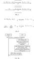
- u P ( u p 2 , u p 1 , u p 4 , u p 3 , ..., u p K , u p K- 1 ), that is, two retransmission information bits in each of sequentially arranged K/2 groups in u P are arranged according to the order reverse to the preset order, as shown in FIG. 4A .
- each of sequentially arranged K/3 groups in u P includes three retransmission information bits, and as shown in FIG. 4B , retransmission information bits in the first group and in the (K/3) th group are arranged according to the order reverse to the preset order, and retransmission information bits in the second group are arranged according to the preset order.
- quantities of retransmission information bits included in all groups of the I groups in the bit sequence u P of the retransmission information may be the same or may be different, and may be set flexibly by a person skilled in the art according to a specific application scenario. This is not described herein.
- the polar code encoding may be performed on u P by using any existing technical solution, or by using a solution obtained by improving the prior art. This is not limited in the present invention.
- a manner of obtaining the bit sequence u P of the retransmission information in S301 is not limited in the present invention.
- a general implementation manner in the present invention is shown in FIG. 5 .
- a person skilled in the art may perform polar code encoding on u P by using an encoder that is different from that used when performing polar code encoding on u A , or may use a same encoder according to a need of a specific implementation manner.
- FIG. 5 is merely an example, and the implementation manner is not limited in the present invention.
- the present invention further discloses multiple manners of obtaining the bit sequence u P of the retransmission information in S301, and each of the following described implementation manners may be combined with S301.
- an implementation manner of obtaining a bit sequence of retransmission information is shown in IFG. 6, and the obtaining the bit sequence u P of the retransmission information specifically includes the following steps:
- another implementation manner of obtaining the bit sequence u P of the retransmission information specifically includes the following steps:
- the retransmission parameter may be sent from a peer network device in a communication process, or may be sent from a control device in a communications network, a forwarder or a server having a similar control function, or the like, as shown in FIG. 7A and FIG. 7B .
- Names of network devices in FIG. 7A and FIG. 7B are merely used as examples.
- the retransmission parameter received in S701 may include information adequate for determining the bit sequence of the retransmission information. That is, in S702, the bit sequence of the retransmission information may be obtained according to the information carried in the retransmission parameter.
- the retransmission parameter may include a rule for determining the K retransmission information bits, and an arrangement manner of the K retransmission information bits, so as to determine the bit sequence of the retransmission information.
- the retransmission parameter received in S701 may include only a part of information for determining the bit sequence of the retransmission information.
- the bit sequence of the retransmission information may be obtained according to the retransmission parameter and pre-stored information.
- the pre-stored information includes at least one of a rule for determining the retransmission information bits or a rule for arranging the retransmission information bits. Specific content of the retransmission parameter and the pre-stored information may be flexibly configured by a person skilled in the art in a specific implementation manner.
- the retransmission parameter may include a rule for determining the K retransmission information bits, and the pre-stored information includes a rule for arranging the K retransmission information bits.
- the retransmission parameter may include an arrangement manner of the K retransmission information bits, and the pre-stored information includes a rule for determining the K retransmission information bits.
- the retransmission parameter may indicate, by using a number, an index, or the like, information carried in the retransmission parameter.
- the bit sequence of the retransmission information is determined according to the information provided by the received retransmission parameter and the pre-stored information.
- the pre-stored information may include a rule for determining the retransmission information bits and a rule for arranging the retransmission information bits.
- the present invention further discloses an implementation manner of obtaining the bit sequence of the retransmission information, that is, obtaining the bit sequence of the retransmission information according to pre-stored information.
- the bit sequence of the retransmission information is determined according to the bit sequence of the first transmission information and the pre-stored information by means of table lookup, calculation, or another similar processing process.
- the pre-stored information includes a rule for determining the retransmission information bits and a rule for arranging the retransmission information bits. This implementation manner does not need to depend on a received retransmission parameter, thereby further saving the transmission resources of the air interface.
- the pre-stored information disclosed in the foregoing embodiments may be in different forms in specific implementation processes. Examples are provided as follows:
- the pre-stored information may be a pre-stored table, and the bit sequence of the retransmission information is determined by looking up the table directly. For example, after the first transmission, the bit sequence of the retransmission information is determined according to the preset table.
- the pre-stored information may be a pre-stored algorithm, and the bit sequence of the retransmission information is determined by means of calculation.
- the retransmission parameter carries a particular number, and the particular number represents a corresponding particular algorithm.
- the bit sequence of the retransmission information may be determined according to the particular algorithm.
- the pre-stored information may be in another form, such as an interleaver designed according to a table or an algorithm.
- the K retransmission information bits may be K bits having lowest reliability among the N first transmission information bits. Because a transmission error probability of the K bits having lowest reliability is relatively high, retransmitting the K bits may greatly improve link performance.
- the K retransmission information bits may be selected from the N first transmission information bits according to a sequential order or according to a reverse order, or may be selected in a random manner or in a pseudo random manner. This is not limited in the present invention and is not described herein.
- the present invention discloses a polar code HARQ method, which is used when multiple times of retransmission need to be performed during data transmission between network devices in a communications system, as shown in FIG. 8 .
- a polar code HARQ method which is used when multiple times of retransmission need to be performed during data transmission between network devices in a communications system, as shown in FIG. 8 .
- For an entity for performing the method 800 shown in FIG. 8 refer to the entity for performing the method disclosed in FIG. 3 . Because S301 to S303 have been described in the foregoing embodiments, only the remaining steps are described below:
- An execution process of S804 is similar to that of S301. It is assumed that the bit sequence u M of the second-time-retransmission information includes the M second-time-retransmission information bits, where 1 ⁇ M ⁇ N.
- the bit sequence of the second-time-retransmission information may be obtained in any one or a combination of the manners described in the foregoing embodiments.
- a method of obtaining the bit sequence of the retransmission information may be the same or different from that of obtaining the bit sequence of the second-time-retransmission information.
- the M second-time-retransmission information bits included in the bit sequence of the second-time-retransmission information may be different from the K retransmission information bits included in the bit sequence of the retransmission information.
- K+M bits are retransmitted, thereby further improving link performance.
- the M second-time-retransmission information bits may be the (K+1) th to the (K+M) th bits having lowest reliability among the N first transmission information bits.
- FIG. 9 shows a polar code HARQ method in a process in which multiple times of retransmission are performed.
- a same polar code encoder and a same polar code encoding solution may be used, or different polar code encoders and different polar code encoding solutions may be used, or similar configuration solutions may be used.
- For a retransmission process from the second time of retransmission refer to the solution disclosed in S804 to S806, which is not described herein again.
- FIG. 10 is a schematic diagram of a polar code encoding apparatus disclosed in the present invention.
- the apparatus 1000 shown in FIG. 10 includes an obtaining circuit 1010 and an encoding circuit 1020.
- the obtaining circuit 1010 is configured to obtain a bit sequence of retransmission information, where the bit sequence of the retransmission information includes K retransmission information bits determined from a bit sequence of first transmission information, the bit sequence of the first transmission information includes N first transmission information bits, N is a positive integer, and K is a positive integer not greater than N.
- the encoding circuit 1020 is configured to perform polar code encoding on the bit sequence of the retransmission information that is obtained by the obtaining circuit 1010, to obtain an encoded retransmission bit sequence.
- the encoding apparatus 1000 may be located in network devices in various forms, such as a macro base station, a micro base station, a repeater, or user equipment, so as to implement an operation of encoding the bit sequence of the retransmission information.
- the encoding apparatus 1000 may be a general-purpose processor, including a central processing unit (CPU, Central Processing Unit), a network processor (NP, Network Processor), and the like, or may be a digital signal processor (DSP, Digital Signal Processor), an application-specific integrated circuit (ASIC, Application Specific Integrated Circuit), a field-programmable gate array (FPGA, Field-Programmable Gate Array), or another programmable logic device, discrete gate, transistor logic device, or discrete hardware component.
- CPU Central Processing Unit
- NP Network Processor
- DSP Digital Signal Processor
- ASIC Application Specific Integrated Circuit
- FPGA Field-Programmable Gate Array
- FPGA Field-Programmable Gate Array
- the obtaining circuit 1010 and the encoding circuit 1020 may be independent from each other and exist separately, or may be integrated together as function components to form a larger sized circuit. Steps of the methods disclosed in the embodiments of the present invention may be directly performed by a hardware encoding processor, or may be performed by using a combination of hardware and software modules in the encoding processor.
- the software module may be located in a storage medium such as a random access memory, a flash memory, a read-only memory, a programmable read-only memory, an electrically erasable programmable memory, or a register.
- the obtaining circuit 1010 may be configured to perform the method described in S301. Refer to the foregoing descriptions for details, which are not described herein again.
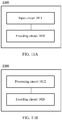
- the obtaining circuit 1010 may be specifically an input circuit 1011, as shown in FIG. 11A .
- the input circuit 1011 is used as an input end of the encoding apparatus 1000, and is specifically configured to input the bit sequence of the retransmission information.
- Input information obtained by the input circuit 1011, that is, the bit sequence of the retransmission information, may be determined by another apparatus.
- the obtaining circuit 1010 may be specifically a processing circuit 1012, as shown in FIG. 11B .
- the processing circuit 1012 is configured to determine the bit sequence of the retransmission information.
- the processing circuit 1012 determines the bit sequence of the retransmission information by performing processing such as bit selection and bit arrangement on the bit sequence of the first transmission information.
- the processing circuit 1012 may be configured to perform the method described in S601 and S602. Refer to the foregoing descriptions for details, which are not described herein again.
- the processing circuit 1012 obtains the bit sequence of the retransmission information according to pre-stored information. Specifically, after first transmission, the bit sequence of the retransmission information is determined according to the bit sequence of the first transmission information and the pre-stored information by means of table lookup, calculation, or another similar processing process.
- the pre-stored information includes a rule for determining the retransmission information bits and a rule for arranging the retransmission information bits.
- the encoding circuit 1020 may be a general-purpose or special-purpose circuit, an encoder, or another circuit having an encoding function, and is configured to perform polar code encoding on the bit sequence of the retransmission information.
- the polar code encoding may be performed by using any existing technical solution, or by using a solution obtained by improving the prior art. This is not limited in the present invention.
- the encoding circuit 1020 may be configured to perform the method described in S302. Refer to the foregoing descriptions for details, which are not described herein again.
- FIG. 12 is a schematic diagram of a polar code communications apparatus disclosed in the present invention.
- the communications apparatus 1200 shown in FIG. 12 includes a receiving circuit 1210 and the polar code encoding apparatus 1000. Specifically:
- the receiving circuit 1210 is configured to receive a retransmission parameter.
- the obtaining circuit 1010 included in the polar code encoding apparatus 1000 is further configured to obtain the bit sequence of the retransmission information according to the retransmission parameter received by the receiving circuit 1210.
- the receiving circuit 1210 and the obtaining circuit 1010 may be configured to perform the method described in S701 and S702. Refer to the foregoing descriptions for details, which are not described herein again.
- the receiving circuit 1210 may be a receiver, or a transceiver into which a transmitting circuit is integrated, or the like.
- FIG. 13 is a schematic diagram of a polar code communications apparatus disclosed in the present invention.
- the communications apparatus 1300 shown in FIG. 13 includes the polar code encoding apparatus 1000 and a transmitting circuit 1310. Specifically:
- the transmitting circuit 1310 is configured to send the encoded retransmission bit sequence to another communications apparatus.
- the encoded retransmission bit sequence is determined by the polar code encoding apparatus 1000.
- the transmitting circuit 1310 may be configured to perform the method described in S301. Refer to the foregoing descriptions for details, which are not described herein again.
- the transmitting circuit 1310 may be a transmitter, or a transceiver into which a receiving circuit is integrated, or the like.
- FIG. 14 is a schematic diagram of a polar code communications apparatus disclosed in the present invention.
- the communications apparatus 1400 shown in FIG. 14 includes the receiving circuit 1210, the polar code encoding apparatus 1000, and the transmitting circuit 1310.
- the communications apparatus 1400 may be configured to perform the methods described in FIG. 3 and FIG. 5 to FIG. 8 . Refer to the foregoing descriptions for details, which are not described herein again.
- the present invention may be implemented by software in addition to necessary general hardware. Based on the understanding, all or a part of the steps of the technical solutions of the present invention may be implemented by a program instructing relevant hardware.
- the program may be stored in a computer readable storage medium. When the program is run, the steps of the method according to the foregoing embodiments are performed.
Description
- The present invention relates to the field of mobile communications technologies, and in particular, to a polar code hybrid automatic repeat request method and an apparatus.
- In a communications system, data transmission reliability is usually improved by means of channel encoding, to ensure communication quality. Polar code (polar code) is an encoding technology to which increasing attention is paid, where a composite channel is constructed and a feature of an original channel is changed, so that a capacity of the composite channel is more polarized. Because of such a feature, by means of appropriate encoding design, the polar code technology may be suitable to an original channel that is randomly distributed, and good performance may be achieved and a channel capacity may be approached in many different channel implementations. In addition, the polar code technology can greatly reduce complexity of a receiver by means of interference cancellation decoding, facilitating implementation of the receiver.
- To improve communication performance, a hybrid automatic repeat request (HARQ, hybrid automatic repeat request) technology may be used. The HARQ is a technology formed by combining forward error correction coding and automatic repeat request, and can efficiently compensate for bit errors caused by link adaptation, thereby improving a data transmission rate and reducing a data transmission delay.
- However, the feature of the polar code technology is different from that of another existing encoding manner. There are apparent differences in transmission quality of input bits and differences in functions of output bits. Therefore, an encoding capability of a polar code cannot be fully used if the existing HARQ technology is used, resulting in poor HARQ performance.
- The paper 'An adaptive hybrid ARQ algorithm for radio channels' by Shacham N., et al (International conference on communications, New York, IEEE, US, Vol, 3, June 23, 1985, pages 1390-1394) describes a HARQ algorithm after receiving a negative acknowledgement.
- The paper 'A practical approach to polar codes' by Eslami A, et. Al (2011 IEEE International SYMPOSIUM on INFORMATION THEORY PROCEEDINGS, St. Petersburg, Russia, 2011-7-31, pages 16-20) describes a concatenated polar codes and rate-compatible polar codes.
- The paper 'A hybrid ARQ scheme based on polar codes' by Chen Kai, et.al (IEEE Communications Letters, Voll7, No.10, ) describes a chase combining HARQ scheme with polar coes.
- The paper 'Polar coded HARQ scheme with chase combining' by Chen Kai, et.al (2014 IEEE Wireless Communications and Networking Conference (WCNC), IEEE, April 6 2014, pages 474-479) describes a chase combining HARQ scheme based on a novel class of rate-compatible polar codes.
- The present invention discloses a polar code hybrid automatic repeat request method and an apparatus, so as to resolve a problem that an existing hybrid automatic repeat request technology fails to fully use an encoding capability of a polar code.
- According to the present invention, the above objects are solved by the claimed matter according to the independent claims.
- Based on the foregoing technical solutions, the polar code hybrid automatic repeat request method and the apparatus that are provided in the embodiments of the present invention can fully use an encoding capability of a polar code, thereby achieving hybrid automatic repeat request performance.
- To describe the technical solutions in the embodiments of the present invention or in the prior art more clearly, the following briefly introduces the accompanying drawings required for describing the embodiments. Apparently, the accompanying drawings in the following description show some embodiments of the present invention, and a person of ordinary skill in the art may still derive other drawings from these accompanying drawings without creative efforts.
-
FIG. 1 is a schematic diagram of a wireless communications system according to an embodiment of the present invention; -
FIG. 2 is a schematic diagram of a polar code encoding system according to an embodiment of the present invention; -
FIG. 3 is a flowchart of a polar code hybrid automatic repeat request method according to an embodiment of the present invention; -
FIG. 4A is a schematic diagram of a bit sequence of retransmission information according to an embodiment of the present invention; -
FIG. 4B is a schematic diagram of another bit sequence of retransmission information according to an embodiment of the present invention; -
FIG. 5 is a flowchart of another polar code hybrid automatic repeat request method according to an embodiment of the present invention; -
FIG. 6 is a flowchart of another polar code hybrid automatic repeat request method according to an embodiment of the present invention; -
FIG. 7A is a flowchart of another polar code hybrid automatic repeat request method according to an embodiment of the present invention; -
FIG. 7B is a flowchart of another polar code hybrid automatic repeat request method according to an embodiment of the present invention; -
FIG. 8 is a flowchart of another polar code hybrid automatic repeat request method according to an embodiment of the present invention; -
FIG. 9 is a flowchart of another polar code hybrid automatic repeat request method according to an embodiment of the present invention; -
FIG. 10 is a schematic diagram of a polar code encoding apparatus according to an embodiment of the present invention; -
FIG. 11A is a schematic diagram of another polar code encoding apparatus according to an embodiment of the present invention; -
FIG. 11B is a schematic diagram of another polar code encoding apparatus according to an embodiment of the present invention; -
FIG. 12 is a schematic diagram of a communications apparatus according to an embodiment of the present invention; -
FIG. 13 is a schematic diagram of another communications apparatus according to an embodiment of the present invention; and -
FIG. 14 is a schematic diagram of another communications apparatus according to an embodiment of the present invention. - To make the objectives, technical solutions, and advantages of the embodiments of the present invention clearer, the following clearly and completely describes the technical solutions in the embodiments of the present invention with reference to the accompanying drawings in the embodiments of the present invention. Apparently, the described embodiments are some but not all of the embodiments of the present invention. All other embodiments obtained by a person of ordinary skill in the art based on the embodiments of the present invention without creative efforts shall fall within the protection scope of the present invention.
- The technical solutions of the present invention may be applied to various communications systems, for example, a Global System for Mobile Communications (GSM, Global System of Mobile communication), a general packet radio service (GPRS, General Packet Radio Service) system, a Code Division Multiple Access (CDMA, Code Division Multiple Access) system, a Wideband Code Division Multiple Access (WCDMA, Wideband Code Division Multiple Access Wireless) system, a Long Term Evolution (LTE, Long Term Evolution) system, and various wireless communications systems evolved and developed subsequently, which include but are not limited to the fifth-generation mobile communications system (5G, 5th Generation) and the like.
- User equipment (UE, User Equipment), also referred to as a mobile terminal (Mobile Terminal), mobile user equipment, or the like, may communicate with one or more core networks (CN, Core Network) through a radio access network (RAN, Radio Access Network). The user equipment may be, for example, a mobile phone or a computer with a mobile terminal. For example, the user equipment may be a portable, pocket-sized, handheld, computer built-in, or in-vehicle mobile apparatus.
- A base station may be a base station (BTS, Base Transceiver Station) in the GSM or CDMA, may be a base station (NodeB) in the WCDMA, or may be an evolved NodeB (eNB or e-NodeB, evolutional Node B) in the LTE, or a network device implementing a similar function in a subsequent evolved system, which is not limited in the present invention. It should be noted that changing a form of a network device correspondingly according to an actual network deployment need, for example, changing the form of the network device to a distributed base station or the like, shall also fall within the protection scope of the present invention.
- A polar code (polar code) hybrid automatic repeat request (HARQ, Hybrid Automatic Repeat Request) method, an apparatus, and a terminal device that are disclosed in the embodiments of the present invention can fully use a capability of a polar code, thereby improving retransmission performance and efficiency of the polar code.
-
FIG. 1 shows awireless communications system 100 according to the embodiments described in the specification. Thesystem 100 includes abase station 102, which may include multiple antenna groups. For example, one antenna group may include anantenna 104 and anantenna 106, another antenna group may include anantenna 108 and anantenna 110, and an additional group may include anantenna 112 and anantenna 114. For each antenna group, two antennas are shown; however, more or fewer antennas may be used for each group. Thebase station 102 may additionally include a transmitter link and a receiver link, and a person of ordinary skill in the art may understand that both the transmitter link and the receiver link may include multiple components related to signal sending and receiving, for example, a processor, a modulator, a multiplexer, a demodulator, a demultiplexer, and an antenna. - The
base station 102 may communicate with one or more access terminals, for example, anaccess terminal 116 and anaccess terminal 122. It may be understood that thebase station 102 may communicate with any quantity of access terminals that are similar to theaccess terminal 116 and theaccess terminal 122. Theaccess terminal 116 and theaccess terminal 122 may be, for example, a cellular phone, a smart phone, a portable computer, a handheld communications device, a handheld computing device, a satellite radio apparatus, a global positioning system, a PDA, or any other suitable devices configured to perform communication in thewireless communications system 100. As shown inFIG. 1 , theaccess terminal 116 communicates with theantenna 112 and theantenna 114, and theantenna 112 and theantenna 114 send information to theaccess terminal 116 by using aforward link 118, and receive information from theaccess terminal 116 by using areverse link 120. Besides, theaccess terminal 122 communicates with theantenna 104 and theantenna 106, and theantenna 104 and theantenna 106 send information to theaccess terminal 122 by using aforward link 124, and receive information from theaccess terminal 122 by using areverse link 126. In a frequency division duplex (FDD, Frequency Division Duplex) system, for example, a frequency band different from that used by thereverse link 120 may be used by theforward link 118, and a frequency band different from that used by thereverse link 126 may be used by theforward link 124. In addition, in a time division duplex (TDD, Time Division Duplex) system, a common frequency band may be used by theforward link 118 and thereverse link 120, and a common frequency band may be used by theforward link 124 and thereverse link 126. - Each antenna group and/or area designed for communication is referred to as a sector of the
base station 102. For example, an antenna group may be designed to communicate with an access terminal in a sector of an area covered by thebase station 102. In communication by using theforward link 118 and theforward link 124, a transmit antenna of thebase station 102 may improve, by means of beamforming, signal-to-noise ratios of theforward link 118 and theforward link 124 for theaccess terminal 116 and theaccess terminal 122. In addition, compared with sending, by the base station by using a single antenna, information to all access terminals of the base station, sending, by thebase station 102 by means of beamforming, information to theaccess terminal 116 and theaccess terminal 122 that are distributed randomly in a related coverage area causes less interference to a mobile device in a neighboring cell. - In a given period of time, the
base station 102, theaccess terminal 116, or theaccess terminal 122 may be a sending wireless communications apparatus or a receiving wireless communications apparatus. When sending data, the sending wireless communications apparatus may encode the data for transmission. Specifically, the sending wireless communications apparatus may have a particular quantity of information bits that need to be sent to the receiving wireless communications apparatus by using a channel. Such information bits may be contained in one or more data transport blocks. In addition, the sending wireless communications apparatus may encode each code block by using a polar code encoder, so as to improve data transmission reliability and ensure communication quality. -
FIG. 2 is a schematic block diagram of asystem 200 applicable to the present invention in a wireless communication environment and applied to a polar code encoding method. Thesystem 200 includes awireless communications device 202. Thewireless communications device 202 may be a base station, for example, thebase station 102 inFIG. 1 , or may be an access terminal, for example, theaccess terminal 116 or theaccess terminal 122 inFIG. 1 . - The
wireless communications device 202 further includes apolar code encoder 204, a rate matching apparatus 205, and atransmitter 206. Optionally, thewireless communications device 202 may further include a receiver. The receiver may exist separately, or may be integrated into thetransmitter 206 to form a transceiver having sending and receiving functions. - The
polar code encoder 204 is configured to encode data to be sent from thewireless communications device 202 to obtain an encoded polar code. - The following describes a specific processing process of the
polar code encoder 204 in detail. It should be noted that these embodiments are merely for helping a person skilled in the art to better understand the present invention, and not for limiting the protection scope of the present invention. -
FIG. 3 is a schematic flowchart of a polar code HARQ method disclosed in the present invention. Themethod 300 shown inFIG. 3 may be performed by a wireless communications device, for example, thepolar code encoder 204 in the wireless communications device shown inFIG. 2 . - S301. Obtain a bit sequence of retransmission information, where the bit sequence of the retransmission information is determined according to K retransmission information bits that are determined from a bit sequence of first transmission information, the bit sequence of the first transmission information includes N first transmission information bits, N is a positive integer, and K is a positive integer not greater than N.
- S302. Perform polar code encoding on the bit sequence of the retransmission information, to obtain an encoded retransmission bit sequence.
- S303. Send the encoded retransmission bit sequence.
- It is assumed that the bit sequence of the first transmission information is u A = (u a
1 , u a2 , ..., uaN ), and a sequence the same as that of the bit sequence of the first transmission information is a preset order. Generally, it is assumed that a 1 < a 2 <···<aN . - In this embodiment, some bits in the bit sequence u A = of the first transmission information need to be encoded and retransmitted. Specifically, it is assumed that the bit sequence of the retransmission information is u P , and includes K retransmission information bits, that is, u p
1 , u p2 , ..., upK , and 1≤K≤N. - Optionally, in S301, the bit sequence of the retransmission information may be u P = (u p
1 , u p2 , ..., upK ), and satisfies p 1 < p 2 <···< pK , that is, the bit sequence u P of the retransmission information is determined according to K retransmission information bits that are determined according to a preset order from the bit sequence u A = of the first transmission information. Because a receive end performs decoding by means of joint decoding, in this case, it is relatively simple for the receive end to implement joint decoding during decoding. - Optionally, in S301, the bit sequence of the retransmission information may be u P = (up
K , u pK-1 , ..., u p1 ), and satisfies p1 < p 2 <···<pK , that is, the bit sequence u P of the retransmission information is determined according to K retransmission information bits that are determined according to an order reverse to a preset order from the bit sequence u A of the first transmission information. Because bits have different reliability in polar code encoding, in this case, as a receive end determines the K retransmission information bits according to the order reverse to the preset order during decoding, positions of bits having different reliability in first transmission can be changed in retransmission, thereby improving link performance in a transmission process. - Optionally, in S301, the bit sequence u P of the retransmission information may satisfy the following conditions:
- (1)

1 , u a2 , ..., uaN ), where p 1 < p 2 < ···< pK , and retransmission information bits included in u P are the same as those in
- (2) u P includes I sequentially arranged groups, where 1≤I≤K. Retransmission information bits included in each of the I groups are arranged according to the preset order or arranged according to the order reverse to the preset order.
- In condition (1), the K retransmission information bits are determined according to the preset order. Specifically, the arrangement order of the K retransmission information bits is the same as that of the K retransmission information bits in the bit sequence u A of the first transmission information. For example, in this embodiment, when a 1 < a 2 <···< aN ,

- For condition (1), an extreme case is K=N, that is, a quantity of the retransmission information bits is the same as a quantity of the first transmission information bits.
- In condition (2), u P includes I groups. An ith group includes K i retransmission information bits, 1≤i≤I, and K = ∑Ki is satisfied.
- For example, when I=K/2, and K i =2, u P = (u p
2 , u p1 , u p4 , u p3 , ..., upK , u pK-1 ), that is, two retransmission information bits in each of sequentially arranged K/2 groups in u P are arranged according to the order reverse to the preset order, as shown inFIG. 4A . - When I=K/3, and K i =3, u P = (u p
3 , up2 , u p1 , u p4 , u p5 , u p6 , ..., upK , u pK-1 , u pK-2 ), that is, each of sequentially arranged K/3 groups in u P includes three retransmission information bits, and as shown inFIG. 4B , retransmission information bits in the first group and in the (K/3)th group are arranged according to the order reverse to the preset order, and retransmission information bits in the second group are arranged according to the preset order. - It should be noted that quantities of retransmission information bits included in all groups of the I groups in the bit sequence u P of the retransmission information may be the same or may be different, and may be set flexibly by a person skilled in the art according to a specific application scenario. This is not described herein.
- In this embodiment, the foregoing mathematical expressions are used merely for ease of description, and should not be construed as a limitation to the protection scope of the present invention.
- In S302, polar code encoding is performed on the bit sequence u P of the retransmission information, to obtain an encoded output sequence, that is, an encoded retransmission bit sequence y P = (y p
1 , y p2 , ..., y pS ), where S is a code length of an encoded polar code. The polar code encoding may be performed on u P by using any existing technical solution, or by using a solution obtained by improving the prior art. This is not limited in the present invention. - It should be noted that in a specific implementation process, a manner of obtaining the bit sequence u P of the retransmission information in S301 is not limited in the present invention. A general implementation manner in the present invention is shown in
FIG. 5 . A person skilled in the art may perform polar code encoding on u P by using an encoder that is different from that used when performing polar code encoding on u A , or may use a same encoder according to a need of a specific implementation manner.FIG. 5 is merely an example, and the implementation manner is not limited in the present invention. - For ease of implementing the present invention, the present invention further discloses multiple manners of obtaining the bit sequence u P of the retransmission information in S301, and each of the following described implementation manners may be combined with S301.
- For example, an implementation manner of obtaining a bit sequence of retransmission information is shown in IFG. 6, and the obtaining the bit sequence u P of the retransmission information specifically includes the following steps:
- S601. Determine K retransmission information bits, that is, select bits. Specifically, the K retransmission information bits are selected from the N first transmission information bits included in the bit sequence u A = of the first transmission information.
- S602. Determine an arrangement order of the K retransmission information bits, that is, arrange the bits. Specifically, the K retransmission information bits selected in S601 are arranged, to obtain the bit sequence u P of the retransmission information.
- For example, another implementation manner of obtaining the bit sequence u P of the retransmission information specifically includes the following steps:
- S701. Receive a retransmission parameter.
- S702. Obtain the bit sequence of the retransmission information according to the retransmission parameter.
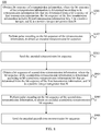
- In S701, the retransmission parameter may be sent from a peer network device in a communication process, or may be sent from a control device in a communications network, a forwarder or a server having a similar control function, or the like, as shown in
FIG. 7A andFIG. 7B . Names of network devices inFIG. 7A andFIG. 7B are merely used as examples. - Optionally, the retransmission parameter received in S701 may include information adequate for determining the bit sequence of the retransmission information. That is, in S702, the bit sequence of the retransmission information may be obtained according to the information carried in the retransmission parameter. For example, the retransmission parameter may include a rule for determining the K retransmission information bits, and an arrangement manner of the K retransmission information bits, so as to determine the bit sequence of the retransmission information.
- Optionally, the retransmission parameter received in S701 may include only a part of information for determining the bit sequence of the retransmission information. In S702, the bit sequence of the retransmission information may be obtained according to the retransmission parameter and pre-stored information. The pre-stored information includes at least one of a rule for determining the retransmission information bits or a rule for arranging the retransmission information bits. Specific content of the retransmission parameter and the pre-stored information may be flexibly configured by a person skilled in the art in a specific implementation manner. For example, the retransmission parameter may include a rule for determining the K retransmission information bits, and the pre-stored information includes a rule for arranging the K retransmission information bits. Alternatively, the retransmission parameter may include an arrangement manner of the K retransmission information bits, and the pre-stored information includes a rule for determining the K retransmission information bits. The foregoing examples and various information combination manners derived from the examples are all within the protection scope of the present invention.
- In addition, in order to save transmission resources of an air interface, the retransmission parameter may indicate, by using a number, an index, or the like, information carried in the retransmission parameter. In S702, the bit sequence of the retransmission information is determined according to the information provided by the received retransmission parameter and the pre-stored information. For example, in this scenario, the pre-stored information may include a rule for determining the retransmission information bits and a rule for arranging the retransmission information bits.
- For example, the present invention further discloses an implementation manner of obtaining the bit sequence of the retransmission information, that is, obtaining the bit sequence of the retransmission information according to pre-stored information. Specifically, after first transmission, the bit sequence of the retransmission information is determined according to the bit sequence of the first transmission information and the pre-stored information by means of table lookup, calculation, or another similar processing process. The pre-stored information includes a rule for determining the retransmission information bits and a rule for arranging the retransmission information bits. This implementation manner does not need to depend on a received retransmission parameter, thereby further saving the transmission resources of the air interface.
- It should be noted that the pre-stored information disclosed in the foregoing embodiments may be in different forms in specific implementation processes. Examples are provided as follows:
The pre-stored information may be a pre-stored table, and the bit sequence of the retransmission information is determined by looking up the table directly. For example, after the first transmission, the bit sequence of the retransmission information is determined according to the preset table. - Alternatively, the pre-stored information may be a pre-stored algorithm, and the bit sequence of the retransmission information is determined by means of calculation. For example, the retransmission parameter carries a particular number, and the particular number represents a corresponding particular algorithm. After the retransmission parameter is received, the bit sequence of the retransmission information may be determined according to the particular algorithm.
- Alternatively, the pre-stored information may be in another form, such as an interleaver designed according to a table or an algorithm.
- In addition, it should be noted that the rule for determining the K retransmission information bits that is disclosed in the foregoing embodiments may be in different forms in specific implementation processes. Examples are provided as follows:
- For example, the K retransmission information bits may be K bits having lowest reliability among the N first transmission information bits. Because a transmission error probability of the K bits having lowest reliability is relatively high, retransmitting the K bits may greatly improve link performance.
- For example, the K retransmission information bits may be selected from the N first transmission information bits according to a sequential order or according to a reverse order, or may be selected in a random manner or in a pseudo random manner. This is not limited in the present invention and is not described herein.
- The present invention discloses a polar code HARQ method, which is used when multiple times of retransmission need to be performed during data transmission between network devices in a communications system, as shown in
FIG. 8 . For an entity for performing themethod 800 shown inFIG. 8 , refer to the entity for performing the method disclosed inFIG. 3 . Because S301 to S303 have been described in the foregoing embodiments, only the remaining steps are described below: - S804. Obtain a bit sequence of second-time-retransmission information, where the bit sequence of the second-time-retransmission information is determined according to M second-time-retransmission information bits that are determined from the bit sequence of the first transmission information, and M is a positive integer not greater than N.
- S805. Perform polar code encoding on the bit sequence of the second-time-retransmission information, to obtain an encoded second-time-retransmission bit sequence.
- S806. Send the encoded second-time-retransmission bit sequence.
- An execution process of S804 is similar to that of S301. It is assumed that the bit sequence u M of the second-time-retransmission information includes the M second-time-retransmission information bits, where 1≤M≤N.
- The bit sequence of the second-time-retransmission information may be obtained in any one or a combination of the manners described in the foregoing embodiments. In addition, a method of obtaining the bit sequence of the retransmission information may be the same or different from that of obtaining the bit sequence of the second-time-retransmission information.
- Optionally, the M second-time-retransmission information bits included in the bit sequence of the second-time-retransmission information may be different from the K retransmission information bits included in the bit sequence of the retransmission information. In this case, K+M bits are retransmitted, thereby further improving link performance.
- Further optionally, when the K retransmission information bits are the K bits having lowest reliability among the N first transmission information bits, the M second-time-retransmission information bits may be the (K+1)th to the (K+M)th bits having lowest reliability among the N first transmission information bits.
- In S805, polar code encoding is performed on u M, to obtain an encoded output sequence, that is, an encoded second-time-retransmission bit sequence y M = (y m
1 , y m2 , ..., ymS ). It should be noted that, during the first transmission and one or more times of retransmission, a same polar code encoding solution may be used, or different polar code encoding solutions may be used. -
FIG. 9 shows a polar code HARQ method in a process in which multiple times of retransmission are performed. In first transmission and each retransmission process, a same polar code encoder and a same polar code encoding solution may be used, or different polar code encoders and different polar code encoding solutions may be used, or similar configuration solutions may be used. For a retransmission process from the second time of retransmission, refer to the solution disclosed in S804 to S806, which is not described herein again. -
FIG. 10 is a schematic diagram of a polar code encoding apparatus disclosed in the present invention. Theapparatus 1000 shown inFIG. 10 includes an obtainingcircuit 1010 and anencoding circuit 1020. Specifically:
The obtainingcircuit 1010 is configured to obtain a bit sequence of retransmission information, where the bit sequence of the retransmission information includes K retransmission information bits determined from a bit sequence of first transmission information, the bit sequence of the first transmission information includes N first transmission information bits, N is a positive integer, and K is a positive integer not greater than N. - The
encoding circuit 1020 is configured to perform polar code encoding on the bit sequence of the retransmission information that is obtained by the obtainingcircuit 1010, to obtain an encoded retransmission bit sequence. - It should be understood that, in a specific application, the
encoding apparatus 1000 may be located in network devices in various forms, such as a macro base station, a micro base station, a repeater, or user equipment, so as to implement an operation of encoding the bit sequence of the retransmission information. Theencoding apparatus 1000 may be a general-purpose processor, including a central processing unit (CPU, Central Processing Unit), a network processor (NP, Network Processor), and the like, or may be a digital signal processor (DSP, Digital Signal Processor), an application-specific integrated circuit (ASIC, Application Specific Integrated Circuit), a field-programmable gate array (FPGA, Field-Programmable Gate Array), or another programmable logic device, discrete gate, transistor logic device, or discrete hardware component. The obtainingcircuit 1010 and theencoding circuit 1020 may be independent from each other and exist separately, or may be integrated together as function components to form a larger sized circuit. Steps of the methods disclosed in the embodiments of the present invention may be directly performed by a hardware encoding processor, or may be performed by using a combination of hardware and software modules in the encoding processor. The software module may be located in a storage medium such as a random access memory, a flash memory, a read-only memory, a programmable read-only memory, an electrically erasable programmable memory, or a register. - The obtaining
circuit 1010 may be configured to perform the method described in S301. Refer to the foregoing descriptions for details, which are not described herein again. - Alternatively, the obtaining
circuit 1010 may be specifically aninput circuit 1011, as shown inFIG. 11A . Specifically, theinput circuit 1011 is used as an input end of theencoding apparatus 1000, and is specifically configured to input the bit sequence of the retransmission information. Input information obtained by theinput circuit 1011, that is, the bit sequence of the retransmission information, may be determined by another apparatus. - Alternatively, the obtaining
circuit 1010 may be specifically aprocessing circuit 1012, as shown inFIG. 11B . Specifically, theprocessing circuit 1012 is configured to determine the bit sequence of the retransmission information. - For example, the
processing circuit 1012 determines the bit sequence of the retransmission information by performing processing such as bit selection and bit arrangement on the bit sequence of the first transmission information. Theprocessing circuit 1012 may be configured to perform the method described in S601 and S602. Refer to the foregoing descriptions for details, which are not described herein again. - For example, the
processing circuit 1012 obtains the bit sequence of the retransmission information according to pre-stored information. Specifically, after first transmission, the bit sequence of the retransmission information is determined according to the bit sequence of the first transmission information and the pre-stored information by means of table lookup, calculation, or another similar processing process. The pre-stored information includes a rule for determining the retransmission information bits and a rule for arranging the retransmission information bits. - The
encoding circuit 1020 may be a general-purpose or special-purpose circuit, an encoder, or another circuit having an encoding function, and is configured to perform polar code encoding on the bit sequence of the retransmission information. The polar code encoding may be performed by using any existing technical solution, or by using a solution obtained by improving the prior art. This is not limited in the present invention. Theencoding circuit 1020 may be configured to perform the method described in S302. Refer to the foregoing descriptions for details, which are not described herein again. -
FIG. 12 is a schematic diagram of a polar code communications apparatus disclosed in the present invention. Thecommunications apparatus 1200 shown inFIG. 12 includes areceiving circuit 1210 and the polarcode encoding apparatus 1000. Specifically: - The receiving
circuit 1210 is configured to receive a retransmission parameter. - The obtaining
circuit 1010 included in the polarcode encoding apparatus 1000 is further configured to obtain the bit sequence of the retransmission information according to the retransmission parameter received by the receivingcircuit 1210. - The receiving
circuit 1210 and the obtainingcircuit 1010 may be configured to perform the method described in S701 and S702. Refer to the foregoing descriptions for details, which are not described herein again. - The receiving
circuit 1210 may be a receiver, or a transceiver into which a transmitting circuit is integrated, or the like. -
FIG. 13 is a schematic diagram of a polar code communications apparatus disclosed in the present invention. Thecommunications apparatus 1300 shown inFIG. 13 includes the polarcode encoding apparatus 1000 and atransmitting circuit 1310. Specifically:
The transmittingcircuit 1310 is configured to send the encoded retransmission bit sequence to another communications apparatus. The encoded retransmission bit sequence is determined by the polarcode encoding apparatus 1000. - The transmitting
circuit 1310 may be configured to perform the method described in S301. Refer to the foregoing descriptions for details, which are not described herein again. - The transmitting
circuit 1310 may be a transmitter, or a transceiver into which a receiving circuit is integrated, or the like. -
FIG. 14 is a schematic diagram of a polar code communications apparatus disclosed in the present invention. Thecommunications apparatus 1400 shown inFIG. 14 includes the receivingcircuit 1210, the polarcode encoding apparatus 1000, and thetransmitting circuit 1310. - The
communications apparatus 1400 may be configured to perform the methods described inFIG. 3 andFIG. 5 toFIG. 8 . Refer to the foregoing descriptions for details, which are not described herein again. - Based on the foregoing descriptions of the embodiments, a person skilled in the art may clearly understand that the present invention may be implemented by software in addition to necessary general hardware. Based on the understanding, all or a part of the steps of the technical solutions of the present invention may be implemented by a program instructing relevant hardware. The program may be stored in a computer readable storage medium. When the program is run, the steps of the method according to the foregoing embodiments are performed.
- The foregoing descriptions are merely specific implementation manners of the present invention, but are not intended to limit the protection scope of the present invention. Any variation or replacement readily figured out by a person skilled in the art within the technical scope disclosed in the present invention shall fall within the protection scope of the present invention. Therefore, the protection scope of the present invention shall be subject to the protection scope of the claims.
Claims (9)
- A polar code hybrid automatic repeat request method, wherein the method comprises:obtaining (S301), by a communications device, a bit sequence of retransmission information, wherein the bit sequence of the retransmission information comprises K retransmission information bits determined from a bit sequence of first transmission information, the bit sequence of the first transmission information comprises N first transmission information bits, N is a positive integer, and K is a positive integer not greater than N;performing(S302), by the communications device, polar code encoding on the bit sequence of the retransmission information, to obtain an encoded retransmission bit sequence; andsending(S303), by the communications device, the encoded retransmission bit sequence to another communications device;wherein the K retransmission information bits in the bit sequence of the retransmission information are arranged according to a preset order or an order reverse to the preset order, and the preset order is the same as an arrangement order of the N bits in the bit sequence of the first transmission information; or the bit sequence of the retransmission information comprises I sequentially arranged groups, wherein retransmission information bits comprised in each of the I groups are arranged according to a preset order or arranged according to an order reverse to the preset order, the preset order is the same as an arrangement order of the N bits in the bit sequence of the first transmission information, and I is a positive integer not greater than K;wherein the K retransmission information bits are K bits having lowest reliability among the N first transmission information bits.
- The method according to claim 1, wherein the method further comprises:receiving (S701) a retransmission parameter; andthe obtaining a bit sequence of the retransmission information(S301) is specifically:
obtaining the bit sequence of the retransmission information according to the retransmission parameter. - The method according to claim 2, wherein the obtaining a bit sequence of the retransmission information according to the retransmission parameter is specifically:
obtaining(S702) the bit sequence of the retransmission information according to the retransmission parameter and pre-stored information, wherein the pre-stored information comprises at least one of a rule for determining the retransmission information bits or a rule for arranging the retransmission information bits. - The method according to claim 1, wherein the obtaining a bit sequence of the retransmission information(S301) is specifically:
obtaining the bit sequence of the retransmission information according to pre-stored information, wherein the pre-stored information comprises a rule for determining the retransmission information bits and a rule for arranging the retransmission information bits. - A polar code encoding apparatus, wherein the apparatus comprises:an obtaining circuit (1010), configured to obtain a bit sequence of retransmission information, wherein the bit sequence of the retransmission information comprises K retransmission information bits determined from a bit sequence of first transmission information, the bit sequence of the first transmission information comprises N first transmission information bits, N is a positive integer, and K is a positive integer not greater than N; andan encoding circuit (1020), configured to perform polar code encoding on the bit sequence of the retransmission information that is obtained by the obtaining circuit, to obtain an encoded retransmission bit sequence;wherein the K retransmission information bits in the bit sequence of the retransmission information are arranged according to a preset order or an order reverse to the preset order, and the preset order is the same as an arrangement order of the N bits in the bit sequence of the first transmission information; or the bit sequence of the retransmission information comprises I sequentially arranged groups, wherein retransmission information bits comprised in each of the I groups are arranged according to a preset order or arranged according to an order reverse to the preset order, the preset order is the same as an arrangement order of the N bits in the bit sequence of the first transmission information, and I is a positive integer not greater than K;wherein the K retransmission information bits are K bits having lowest reliability among the N first transmission information bits.
- The apparatus according to claim 5, wherein the obtaining circuit (1010) is further configured to:
obtain the bit sequence of the retransmission information according to pre-stored information, wherein the pre-stored information comprises a rule for determining the retransmission information bits and a rule for arranging the retransmission information bits. - A communications apparatus, wherein the apparatus comprises:a receiving circuit (1210), configured to receive a retransmission parameter; andthe polar code encoding apparatus according to any one of claims 5 or 6, wherein
the obtaining circuit (1010) is further configured to obtain the bit sequence of the retransmission information according to the retransmission parameter received by the receiving circuit. - The apparatus according to claim 7, wherein the obtaining circuit (1010) is further configured to:
obtain the bit sequence of the retransmission information according to the retransmission parameter and pre-stored information, wherein the pre-stored information comprises at least one of a rule for determining the retransmission information bits or a rule for arranging the retransmission information bits. - A communications apparatus, wherein the apparatus comprises:the polar code encoding apparatus according to any one of claims 5 to 8; anda transmitting circuit (1310), configured to send the encoded retransmission bit sequence to another communications apparatus.
Applications Claiming Priority (1)
| Application Number | Priority Date | Filing Date | Title |
|---|---|---|---|
| PCT/CN2015/075727 WO2016154972A1 (en) | 2015-04-01 | 2015-04-01 | Polar code hybrid automatic retransmission request method and device |
Publications (3)
| Publication Number | Publication Date |
|---|---|
| EP3264651A1 EP3264651A1 (en) | 2018-01-03 |
| EP3264651A4 EP3264651A4 (en) | 2018-04-04 |
| EP3264651B1 true EP3264651B1 (en) | 2020-05-06 |
Family
ID=57004709
Family Applications (1)
| Application Number | Title | Priority Date | Filing Date |
|---|---|---|---|
| EP15886942.0A Active EP3264651B1 (en) | 2015-04-01 | 2015-04-01 | Polar code hybrid automatic retransmission request method and device |
Country Status (4)
| Country | Link |
|---|---|
| US (1) | US10484137B2 (en) |
| EP (1) | EP3264651B1 (en) |
| CN (1) | CN107409006B (en) |
| WO (1) | WO2016154972A1 (en) |
Families Citing this family (9)
| Publication number | Priority date | Publication date | Assignee | Title |
|---|---|---|---|---|
| US10461779B2 (en) * | 2015-08-12 | 2019-10-29 | Telefonaktiebolaget Lm Ericsson (Publ) | Rate-compatible polar codes |
| WO2018083647A1 (en) * | 2016-11-03 | 2018-05-11 | Telefonaktiebolaget Lm Ericsson (Publ) | Systems and methods for rate-compatible polar codes for general channels |
| CN117375765A (en) * | 2017-01-05 | 2024-01-09 | 华为技术有限公司 | Rate matching method, encoding device and communication device |
| WO2018126458A1 (en) * | 2017-01-06 | 2018-07-12 | Nokia Technologies Oy | Retransmission of polar code with reordered information bits |
| EP3610594B1 (en) | 2017-05-05 | 2023-08-30 | Huawei Technologies Co., Ltd. | Method and device for incremental redundancy hybrid automatic repeat request (ir-harq) re-transmission |
| US10700710B2 (en) * | 2017-07-24 | 2020-06-30 | Qualcomm Incorporated | Indicating a number of copied information bits in a retransmission |
| WO2019153301A1 (en) | 2018-02-11 | 2019-08-15 | Qualcomm Incorporated | Retransmission of physical uplink control channel (pucch) for ultra reliable low latency communications (urllc) |
| CN115085862A (en) * | 2021-03-16 | 2022-09-20 | 中兴通讯股份有限公司 | Data transmission method, device and storage medium |
| CN115913472A (en) * | 2021-09-30 | 2023-04-04 | 华为技术有限公司 | Retransmission method and device |
Family Cites Families (9)
| Publication number | Priority date | Publication date | Assignee | Title |
|---|---|---|---|---|
| CN101064708B (en) * | 2006-04-30 | 2010-04-21 | 华为技术有限公司 | Multi-carrier system frequency resource mapping method and apparatus |
| WO2008034285A1 (en) * | 2006-09-18 | 2008-03-27 | Fengwen Sun | A family of ldpc codes for video broadcasting applications |
| CN102017506B (en) * | 2008-03-16 | 2014-06-04 | Lg电子株式会社 | Method of performing hybrid automatic repeat request (HARQ) in wireless communication system |
| US8301979B2 (en) * | 2008-10-07 | 2012-10-30 | Sandisk Il Ltd. | Low density parity code (LDPC) decoding for memory with multiple log likelihood ratio (LLR) decoders |
| CN103516476B (en) | 2012-06-29 | 2016-12-21 | 华为技术有限公司 | Coded method and equipment |
| CN103281166B (en) * | 2013-05-15 | 2016-05-25 | 北京邮电大学 | A kind of mixed automatic retransfer request transmission method based on polarization code |
| USRE49547E1 (en) * | 2013-08-20 | 2023-06-06 | Lg Electronics Inc. | Method for transmitting data by using polar coding in wireless access system |
| CA2972642C (en) | 2014-03-21 | 2020-05-26 | Huawei Technologies Co., Ltd. | Polar code retransmission method and apparatus |
| US9742440B2 (en) * | 2015-03-25 | 2017-08-22 | Samsung Electronics Co., Ltd | HARQ rate-compatible polar codes for wireless channels |
-
2015
- 2015-04-01 EP EP15886942.0A patent/EP3264651B1/en active Active
- 2015-04-01 CN CN201580077235.3A patent/CN107409006B/en active Active
- 2015-04-01 WO PCT/CN2015/075727 patent/WO2016154972A1/en active Application Filing
-
2017
- 2017-09-29 US US15/719,832 patent/US10484137B2/en active Active
Non-Patent Citations (1)
| Title |
|---|
| None * |
Also Published As
| Publication number | Publication date |
|---|---|
| CN107409006B (en) | 2020-04-21 |
| US20180026751A1 (en) | 2018-01-25 |
| EP3264651A1 (en) | 2018-01-03 |
| CN107409006A (en) | 2017-11-28 |
| US10484137B2 (en) | 2019-11-19 |
| WO2016154972A1 (en) | 2016-10-06 |
| EP3264651A4 (en) | 2018-04-04 |
Similar Documents
| Publication | Publication Date | Title |
|---|---|---|
| EP3264651B1 (en) | Polar code hybrid automatic retransmission request method and device | |
| US10966118B2 (en) | Channel encoding method and communication device | |
| EP3079290B1 (en) | Method and apparatus for rate matching of polar code | |
| US10574401B2 (en) | Polar code retransmission method and apparatus | |
| EP3073660A1 (en) | Polar code processing method and device | |
| US10938422B2 (en) | Polar code rate matching method and apparatus, and a communications apparatus | |
| KR20220037414A (en) | Method and terminal device for transmitting data | |
| WO2017124844A1 (en) | Method for determining transmission block size of polarisation code, and communication device | |
| US10419161B2 (en) | Method and communications device for transmitting information | |
| EP3979532B1 (en) | Method for polar decoding and apparatus | |
| US11405159B2 (en) | Method for transmitting feedback information, terminal device and network device | |
| US20230336273A1 (en) | Hybrid automatic repeat request harq-based communication method and apparatus | |
| JP2020503776A (en) | Method, terminal device, and network device for transmitting data on multiple carriers | |
| CN111757505B (en) | Communication method, terminal device and network device | |
| US20220095344A1 (en) | Method and terminal equipment for harq feedback | |
| EP3567767A1 (en) | Data processing method and device | |
| WO2017193932A1 (en) | Communication method and network device thereof, and user equipment | |
| KR20200118807A (en) | Wireless communication method and device | |
| JP6571213B6 (en) | Data storage method, terminal device and base station | |
| CN114302408B (en) | Wireless communication method, terminal equipment and network equipment | |
| CN110545154B (en) | Method and apparatus for signal processing | |
| CN114205874A (en) | Communication method and device | |
| CN109417522B (en) | Data transmission method, receiving end equipment and sending end equipment | |
| CN111262647A (en) | Data transmission method and device | |
| EP3667965A1 (en) | Coding method and device |
Legal Events
| Date | Code | Title | Description |
|---|---|---|---|
| STAA | Information on the status of an ep patent application or granted ep patent |
Free format text: STATUS: THE INTERNATIONAL PUBLICATION HAS BEEN MADE |
|
| PUAI | Public reference made under article 153(3) epc to a published international application that has entered the european phase |
Free format text: ORIGINAL CODE: 0009012 |
|
| STAA | Information on the status of an ep patent application or granted ep patent |
Free format text: STATUS: REQUEST FOR EXAMINATION WAS MADE |
|
| 17P | Request for examination filed |
Effective date: 20170927 |
|
| AK | Designated contracting states |
Kind code of ref document: A1 Designated state(s): AL AT BE BG CH CY CZ DE DK EE ES FI FR GB GR HR HU IE IS IT LI LT LU LV MC MK MT NL NO PL PT RO RS SE SI SK SM TR |
|
| AX | Request for extension of the european patent |
Extension state: BA ME |
|
| A4 | Supplementary search report drawn up and despatched |
Effective date: 20180307 |
|
| RIC1 | Information provided on ipc code assigned before grant |
Ipc: H03M 13/13 20060101ALI20180301BHEP Ipc: H04L 1/00 20060101AFI20180301BHEP Ipc: H04L 1/18 20060101ALI20180301BHEP |
|
| DAV | Request for validation of the european patent (deleted) | ||
| DAX | Request for extension of the european patent (deleted) | ||
| STAA | Information on the status of an ep patent application or granted ep patent |
Free format text: STATUS: EXAMINATION IS IN PROGRESS |
|
| 17Q | First examination report despatched |
Effective date: 20190808 |
|
| GRAP | Despatch of communication of intention to grant a patent |
Free format text: ORIGINAL CODE: EPIDOSNIGR1 |
|
| STAA | Information on the status of an ep patent application or granted ep patent |
Free format text: STATUS: GRANT OF PATENT IS INTENDED |
|
| INTG | Intention to grant announced |
Effective date: 20200130 |
|
| GRAS | Grant fee paid |
Free format text: ORIGINAL CODE: EPIDOSNIGR3 |
|
| GRAA | (expected) grant |
Free format text: ORIGINAL CODE: 0009210 |
|
| STAA | Information on the status of an ep patent application or granted ep patent |
Free format text: STATUS: THE PATENT HAS BEEN GRANTED |
|
| AK | Designated contracting states |
Kind code of ref document: B1 Designated state(s): AL AT BE BG CH CY CZ DE DK EE ES FI FR GB GR HR HU IE IS IT LI LT LU LV MC MK MT NL NO PL PT RO RS SE SI SK SM TR |
|
| REG | Reference to a national code |
Ref country code: GB Ref legal event code: FG4D |
|
| REG | Reference to a national code |
Ref country code: CH Ref legal event code: EP Ref country code: AT Ref legal event code: REF Ref document number: 1268519 Country of ref document: AT Kind code of ref document: T Effective date: 20200515 |
|
| REG | Reference to a national code |
Ref country code: IE Ref legal event code: FG4D |
|
| REG | Reference to a national code |
Ref country code: DE Ref legal event code: R096 Ref document number: 602015052579 Country of ref document: DE |
|
| REG | Reference to a national code |
Ref country code: LT Ref legal event code: MG4D |
|
| REG | Reference to a national code |
Ref country code: NL Ref legal event code: MP Effective date: 20200506 |
|
| PG25 | Lapsed in a contracting state [announced via postgrant information from national office to epo] |
Ref country code: SE Free format text: LAPSE BECAUSE OF FAILURE TO SUBMIT A TRANSLATION OF THE DESCRIPTION OR TO PAY THE FEE WITHIN THE PRESCRIBED TIME-LIMIT Effective date: 20200506 Ref country code: LT Free format text: LAPSE BECAUSE OF FAILURE TO SUBMIT A TRANSLATION OF THE DESCRIPTION OR TO PAY THE FEE WITHIN THE PRESCRIBED TIME-LIMIT Effective date: 20200506 Ref country code: PT Free format text: LAPSE BECAUSE OF FAILURE TO SUBMIT A TRANSLATION OF THE DESCRIPTION OR TO PAY THE FEE WITHIN THE PRESCRIBED TIME-LIMIT Effective date: 20200907 Ref country code: IS Free format text: LAPSE BECAUSE OF FAILURE TO SUBMIT A TRANSLATION OF THE DESCRIPTION OR TO PAY THE FEE WITHIN THE PRESCRIBED TIME-LIMIT Effective date: 20200906 Ref country code: FI Free format text: LAPSE BECAUSE OF FAILURE TO SUBMIT A TRANSLATION OF THE DESCRIPTION OR TO PAY THE FEE WITHIN THE PRESCRIBED TIME-LIMIT Effective date: 20200506 Ref country code: NO Free format text: LAPSE BECAUSE OF FAILURE TO SUBMIT A TRANSLATION OF THE DESCRIPTION OR TO PAY THE FEE WITHIN THE PRESCRIBED TIME-LIMIT Effective date: 20200806 Ref country code: GR Free format text: LAPSE BECAUSE OF FAILURE TO SUBMIT A TRANSLATION OF THE DESCRIPTION OR TO PAY THE FEE WITHIN THE PRESCRIBED TIME-LIMIT Effective date: 20200807 |
|
| PG25 | Lapsed in a contracting state [announced via postgrant information from national office to epo] |
Ref country code: LV Free format text: LAPSE BECAUSE OF FAILURE TO SUBMIT A TRANSLATION OF THE DESCRIPTION OR TO PAY THE FEE WITHIN THE PRESCRIBED TIME-LIMIT Effective date: 20200506 Ref country code: RS Free format text: LAPSE BECAUSE OF FAILURE TO SUBMIT A TRANSLATION OF THE DESCRIPTION OR TO PAY THE FEE WITHIN THE PRESCRIBED TIME-LIMIT Effective date: 20200506 Ref country code: BG Free format text: LAPSE BECAUSE OF FAILURE TO SUBMIT A TRANSLATION OF THE DESCRIPTION OR TO PAY THE FEE WITHIN THE PRESCRIBED TIME-LIMIT Effective date: 20200806 Ref country code: HR Free format text: LAPSE BECAUSE OF FAILURE TO SUBMIT A TRANSLATION OF THE DESCRIPTION OR TO PAY THE FEE WITHIN THE PRESCRIBED TIME-LIMIT Effective date: 20200506 |
|
| REG | Reference to a national code |
Ref country code: AT Ref legal event code: MK05 Ref document number: 1268519 Country of ref document: AT Kind code of ref document: T Effective date: 20200506 |
|
| PG25 | Lapsed in a contracting state [announced via postgrant information from national office to epo] |
Ref country code: NL Free format text: LAPSE BECAUSE OF FAILURE TO SUBMIT A TRANSLATION OF THE DESCRIPTION OR TO PAY THE FEE WITHIN THE PRESCRIBED TIME-LIMIT Effective date: 20200506 Ref country code: AL Free format text: LAPSE BECAUSE OF FAILURE TO SUBMIT A TRANSLATION OF THE DESCRIPTION OR TO PAY THE FEE WITHIN THE PRESCRIBED TIME-LIMIT Effective date: 20200506 |
|
| PG25 | Lapsed in a contracting state [announced via postgrant information from national office to epo] |
Ref country code: IT Free format text: LAPSE BECAUSE OF FAILURE TO SUBMIT A TRANSLATION OF THE DESCRIPTION OR TO PAY THE FEE WITHIN THE PRESCRIBED TIME-LIMIT Effective date: 20200506 Ref country code: CZ Free format text: LAPSE BECAUSE OF FAILURE TO SUBMIT A TRANSLATION OF THE DESCRIPTION OR TO PAY THE FEE WITHIN THE PRESCRIBED TIME-LIMIT Effective date: 20200506 Ref country code: ES Free format text: LAPSE BECAUSE OF FAILURE TO SUBMIT A TRANSLATION OF THE DESCRIPTION OR TO PAY THE FEE WITHIN THE PRESCRIBED TIME-LIMIT Effective date: 20200506 Ref country code: SM Free format text: LAPSE BECAUSE OF FAILURE TO SUBMIT A TRANSLATION OF THE DESCRIPTION OR TO PAY THE FEE WITHIN THE PRESCRIBED TIME-LIMIT Effective date: 20200506 Ref country code: EE Free format text: LAPSE BECAUSE OF FAILURE TO SUBMIT A TRANSLATION OF THE DESCRIPTION OR TO PAY THE FEE WITHIN THE PRESCRIBED TIME-LIMIT Effective date: 20200506 Ref country code: RO Free format text: LAPSE BECAUSE OF FAILURE TO SUBMIT A TRANSLATION OF THE DESCRIPTION OR TO PAY THE FEE WITHIN THE PRESCRIBED TIME-LIMIT Effective date: 20200506 Ref country code: AT Free format text: LAPSE BECAUSE OF FAILURE TO SUBMIT A TRANSLATION OF THE DESCRIPTION OR TO PAY THE FEE WITHIN THE PRESCRIBED TIME-LIMIT Effective date: 20200506 Ref country code: DK Free format text: LAPSE BECAUSE OF FAILURE TO SUBMIT A TRANSLATION OF THE DESCRIPTION OR TO PAY THE FEE WITHIN THE PRESCRIBED TIME-LIMIT Effective date: 20200506 |
|
| REG | Reference to a national code |
Ref country code: DE Ref legal event code: R097 Ref document number: 602015052579 Country of ref document: DE |
|
| PG25 | Lapsed in a contracting state [announced via postgrant information from national office to epo] |
Ref country code: SK Free format text: LAPSE BECAUSE OF FAILURE TO SUBMIT A TRANSLATION OF THE DESCRIPTION OR TO PAY THE FEE WITHIN THE PRESCRIBED TIME-LIMIT Effective date: 20200506 Ref country code: PL Free format text: LAPSE BECAUSE OF FAILURE TO SUBMIT A TRANSLATION OF THE DESCRIPTION OR TO PAY THE FEE WITHIN THE PRESCRIBED TIME-LIMIT Effective date: 20200506 |
|
| PLBE | No opposition filed within time limit |
Free format text: ORIGINAL CODE: 0009261 |
|
| STAA | Information on the status of an ep patent application or granted ep patent |
Free format text: STATUS: NO OPPOSITION FILED WITHIN TIME LIMIT |
|
| 26N | No opposition filed |
Effective date: 20210209 |
|
| PG25 | Lapsed in a contracting state [announced via postgrant information from national office to epo] |
Ref country code: SI Free format text: LAPSE BECAUSE OF FAILURE TO SUBMIT A TRANSLATION OF THE DESCRIPTION OR TO PAY THE FEE WITHIN THE PRESCRIBED TIME-LIMIT Effective date: 20200506 |
|
| REG | Reference to a national code |
Ref country code: DE Ref legal event code: R119 Ref document number: 602015052579 Country of ref document: DE |
|
| PG25 | Lapsed in a contracting state [announced via postgrant information from national office to epo] |
Ref country code: MC Free format text: LAPSE BECAUSE OF FAILURE TO SUBMIT A TRANSLATION OF THE DESCRIPTION OR TO PAY THE FEE WITHIN THE PRESCRIBED TIME-LIMIT Effective date: 20200506 |
|
| PG25 | Lapsed in a contracting state [announced via postgrant information from national office to epo] |
Ref country code: LU Free format text: LAPSE BECAUSE OF NON-PAYMENT OF DUE FEES Effective date: 20210401 |
|
| REG | Reference to a national code |
Ref country code: BE Ref legal event code: MM Effective date: 20210430 |
|
| PG25 | Lapsed in a contracting state [announced via postgrant information from national office to epo] |
Ref country code: DE Free format text: LAPSE BECAUSE OF NON-PAYMENT OF DUE FEES Effective date: 20211103 Ref country code: FR Free format text: LAPSE BECAUSE OF NON-PAYMENT OF DUE FEES Effective date: 20210430 Ref country code: LI Free format text: LAPSE BECAUSE OF NON-PAYMENT OF DUE FEES Effective date: 20210430 Ref country code: CH Free format text: LAPSE BECAUSE OF NON-PAYMENT OF DUE FEES Effective date: 20210430 |
|
| PG25 | Lapsed in a contracting state [announced via postgrant information from national office to epo] |
Ref country code: IE Free format text: LAPSE BECAUSE OF NON-PAYMENT OF DUE FEES Effective date: 20210401 |
|
| PG25 | Lapsed in a contracting state [announced via postgrant information from national office to epo] |
Ref country code: BE Free format text: LAPSE BECAUSE OF NON-PAYMENT OF DUE FEES Effective date: 20210430 |
|
| PG25 | Lapsed in a contracting state [announced via postgrant information from national office to epo] |
Ref country code: HU Free format text: LAPSE BECAUSE OF FAILURE TO SUBMIT A TRANSLATION OF THE DESCRIPTION OR TO PAY THE FEE WITHIN THE PRESCRIBED TIME-LIMIT; INVALID AB INITIO Effective date: 20150401 |
|
| PGFP | Annual fee paid to national office [announced via postgrant information from national office to epo] |
Ref country code: GB Payment date: 20230302 Year of fee payment: 9 |
|
| PG25 | Lapsed in a contracting state [announced via postgrant information from national office to epo] |
Ref country code: CY Free format text: LAPSE BECAUSE OF FAILURE TO SUBMIT A TRANSLATION OF THE DESCRIPTION OR TO PAY THE FEE WITHIN THE PRESCRIBED TIME-LIMIT Effective date: 20200506 |
|
| PG25 | Lapsed in a contracting state [announced via postgrant information from national office to epo] |
Ref country code: MK Free format text: LAPSE BECAUSE OF FAILURE TO SUBMIT A TRANSLATION OF THE DESCRIPTION OR TO PAY THE FEE WITHIN THE PRESCRIBED TIME-LIMIT Effective date: 20200506 |
|
| PGFP | Annual fee paid to national office [announced via postgrant information from national office to epo] |
Ref country code: GB Payment date: 20240229 Year of fee payment: 10 |