EP3260272B1 - Device for the production of at least one three-dimensional component for the building industry - Google Patents
Device for the production of at least one three-dimensional component for the building industry Download PDFInfo
- Publication number
- EP3260272B1 EP3260272B1 EP17177714.7A EP17177714A EP3260272B1 EP 3260272 B1 EP3260272 B1 EP 3260272B1 EP 17177714 A EP17177714 A EP 17177714A EP 3260272 B1 EP3260272 B1 EP 3260272B1
- Authority
- EP
- European Patent Office
- Prior art keywords
- printing
- delimiting
- particulate material
- frame
- printing platform
- Prior art date
- Legal status (The legal status is an assumption and is not a legal conclusion. Google has not performed a legal analysis and makes no representation as to the accuracy of the status listed.)
- Active
Links
Images

Classifications
-
- B—PERFORMING OPERATIONS; TRANSPORTING
- B29—WORKING OF PLASTICS; WORKING OF SUBSTANCES IN A PLASTIC STATE IN GENERAL
- B29C—SHAPING OR JOINING OF PLASTICS; SHAPING OF MATERIAL IN A PLASTIC STATE, NOT OTHERWISE PROVIDED FOR; AFTER-TREATMENT OF THE SHAPED PRODUCTS, e.g. REPAIRING
- B29C64/00—Additive manufacturing, i.e. manufacturing of three-dimensional [3D] objects by additive deposition, additive agglomeration or additive layering, e.g. by 3D printing, stereolithography or selective laser sintering
- B29C64/10—Processes of additive manufacturing
- B29C64/165—Processes of additive manufacturing using a combination of solid and fluid materials, e.g. a powder selectively bound by a liquid binder, catalyst, inhibitor or energy absorber
-
- B—PERFORMING OPERATIONS; TRANSPORTING
- B28—WORKING CEMENT, CLAY, OR STONE
- B28B—SHAPING CLAY OR OTHER CERAMIC COMPOSITIONS; SHAPING SLAG; SHAPING MIXTURES CONTAINING CEMENTITIOUS MATERIAL, e.g. PLASTER
- B28B13/00—Feeding the unshaped material to moulds or apparatus for producing shaped articles; Discharging shaped articles from such moulds or apparatus
- B28B13/02—Feeding the unshaped material to moulds or apparatus for producing shaped articles
- B28B13/0215—Feeding the moulding material in measured quantities from a container or silo
- B28B13/023—Feeding the moulding material in measured quantities from a container or silo by using a feed box transferring the moulding material from a hopper to the moulding cavities
-
- B—PERFORMING OPERATIONS; TRANSPORTING
- B29—WORKING OF PLASTICS; WORKING OF SUBSTANCES IN A PLASTIC STATE IN GENERAL
- B29C—SHAPING OR JOINING OF PLASTICS; SHAPING OF MATERIAL IN A PLASTIC STATE, NOT OTHERWISE PROVIDED FOR; AFTER-TREATMENT OF THE SHAPED PRODUCTS, e.g. REPAIRING
- B29C64/00—Additive manufacturing, i.e. manufacturing of three-dimensional [3D] objects by additive deposition, additive agglomeration or additive layering, e.g. by 3D printing, stereolithography or selective laser sintering
- B29C64/20—Apparatus for additive manufacturing; Details thereof or accessories therefor
- B29C64/255—Enclosures for the building material, e.g. powder containers
- B29C64/259—Interchangeable
-
- E—FIXED CONSTRUCTIONS
- E04—BUILDING
- E04B—GENERAL BUILDING CONSTRUCTIONS; WALLS, e.g. PARTITIONS; ROOFS; FLOORS; CEILINGS; INSULATION OR OTHER PROTECTION OF BUILDINGS
- E04B1/00—Constructions in general; Structures which are not restricted either to walls, e.g. partitions, or floors or ceilings or roofs
- E04B1/35—Extraordinary methods of construction, e.g. lift-slab, jack-block
- E04B1/3505—Extraordinary methods of construction, e.g. lift-slab, jack-block characterised by the in situ moulding of large parts of a structure
-
- B—PERFORMING OPERATIONS; TRANSPORTING
- B28—WORKING CEMENT, CLAY, OR STONE
- B28B—SHAPING CLAY OR OTHER CERAMIC COMPOSITIONS; SHAPING SLAG; SHAPING MIXTURES CONTAINING CEMENTITIOUS MATERIAL, e.g. PLASTER
- B28B1/00—Producing shaped prefabricated articles from the material
- B28B1/001—Rapid manufacturing of 3D objects by additive depositing, agglomerating or laminating of material
-
- B—PERFORMING OPERATIONS; TRANSPORTING
- B29—WORKING OF PLASTICS; WORKING OF SUBSTANCES IN A PLASTIC STATE IN GENERAL
- B29C—SHAPING OR JOINING OF PLASTICS; SHAPING OF MATERIAL IN A PLASTIC STATE, NOT OTHERWISE PROVIDED FOR; AFTER-TREATMENT OF THE SHAPED PRODUCTS, e.g. REPAIRING
- B29C64/00—Additive manufacturing, i.e. manufacturing of three-dimensional [3D] objects by additive deposition, additive agglomeration or additive layering, e.g. by 3D printing, stereolithography or selective laser sintering
- B29C64/30—Auxiliary operations or equipment
- B29C64/357—Recycling
Definitions
- the subject invention relates to the technical field of 3D printing in the construction industry.
- essentially three types of processes are distinguished from each other, two of these types of processes, namely "Contour Crafting” and “Concrete Printing” are very related and define processes in which a viscous concrete mix is sprayed through nozzles in situ and cures itself.
- a particulate material is applied in layers and solidified in locally predetermined areas by dispensing at least one binder and bonded together.
- the WO2006 / 100556 A2 describes a device for producing a three-dimensional component by additive manufacturing.
- the object of the present invention is thus to provide an improved over the prior art device according to the preamble of claim 1 and a method for operating such a device, wherein said device, the disadvantages mentioned are avoided, and which device makes it possible in particular , the Print platform to remain stationary during the printing process and at the same time provide a cost-effective and practical solution for lateral limitation of the particulate material.
- a coupling device is provided, with which a limiting device for lateral delimitation of the particulate material with the at least one pressure frame is detachably coupled, so that the limiting device with the printing frame at a Adjustment is mitbewegbar at least in the vertical direction.
- a great advantage consists in that the printing platform together with the limiting device and the at least one produced three-dimensional component can be removed from the printing frame and transported to a demoulding area where the demoulding of the at least one produced three-dimensional component takes place.
- loose material escapes which is not part of the component. This can lead to an unfavorable development of dust. If one were to carry out the demolding directly in the area of the printing frame, then there would be the risk that the loose material components of the printing frame, such as the drive of the print head, damaged. This danger is completely banned if demolding takes place in a separate location.
- the printing frame would make accessibility to the at least one manufactured three-dimensional component difficult. This disadvantage can also be eliminated by the present invention.
- the demolding offers at a separate location from the printing frame the ability to speed up the production, since immediately after the removal of the package of printing platform including the limiting device and the at least one manufactured three-dimensional component already started printing another component on a new printing platform without having to wait for demoulding.
- the coupling device with which a limiting device for lateral delimitation of the particulate material with the at least one pressure frame is releasably coupled, and optionally the coupling device with which the limiting device for lateral delimitation of the particulate material with the pressure platform and / or an optionally present transport device is releasably coupled, at least one, preferably four, locking bolt and corresponding recesses comprises.
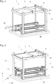
- FIG. 1 shows a transport device 13, with which a printing platform 3 (see for example Fig. 2 ) in the device 1 (see for example Figure 4 ) and can be removed again after completion of the printing operation of the device 1.
- the transport device 13 comprises a frame 16 on which rolling bodies 17, preferably in the form of wheels, for supporting the transport device 13 are arranged on a substrate.
- the transport device 13 is supported by four such rolling elements 17.
- the rolling elements 17 can each be driven by means of an electric motor 18.
- the rolling elements 17 are arranged in the operating position of the transport device 13 on the underside of the frame 16.
- FIG. 2 shows the transport device 13 with a printing platform arranged thereon 3.
- the printing platform 3 has a support structure 32, on which a in use position horizontally aligned flat plate 33, which may also be segmented, is arranged.
- the printing platform 3 is also essentially made of steel.
- the transport device 13 and the printing platform 3 are statically constructed so that there is no torsion or deflection in the frame construction.
- the printing platform 3 can be positioned by means of a lifting device, for example in the form of a forklift, on the transport device 13 and removed therefrom again and fed, for example, to a further station such as an unpacking system, a dryer area or a storage area.
- FIG. 3 shows the arrangement of the transport device 13 and the printing platform 3 according to FIG. 2 in combination with a restriction device 12 for lateral confinement of particulate matter.
- the limiting device 12 is essentially formed of four walls 19, 20, 21 and 22 arranged at right angles to one another. These walls 19, 20, 21 and 22 represent the side walls of an imaginary parallelepiped body.
- the walls 19, 20, 21 and 22 of the limiting device 12 essentially consist of aluminum hollow profiles and are thus made of a lighter material than the printing platform 3 and the transport device 13 built up.
- the walls 19, 20, 21 and 22 are formed rigid, so that there is no deformation when in the course of the printing operation on the printing platform 3 and in the interior of the limiting device 12 particulate material 4 is arranged.
- the walls 19, 20, 21 and 22 at least on its inner surface on a smooth surface with a low coefficient of friction, whereby adhesion of the particulate material 4 can be avoided. This means that the walls 19, 20, 21 and 22 can be moved relative to the particulate material 4, without there being any appreciable change in the spatial position of the adjacent particulate material 4.
- the limiting device 12 has a height 23 of 1.5 m, a width 24 of 4 m and a depth 25 of 2 m. This results in a pressure volume of 12 m 3 . If necessary, the dimensions of the limiting device 12 can also be adapted to larger or smaller pressure volumes.
- a coupling device 10, 11 is provided, with which the limiting device 12 with the Print platform 3 is releasably coupled.
- the coupling device is formed from four locking pins 10, which engage in corresponding recesses 11, wherein these corresponding recesses 11 are arranged both in the limiting device 12 and in the printing platform 3.
- recesses 11 are used, which are formed in the use position in the lower region of the limiting device 12.
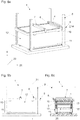
- FIG. 4 now shows a preferred embodiment of an apparatus 1 for producing at least one three-dimensional component for the construction industry.
- the device 1 comprises a frame 8, which is essentially formed of four aligned in the vertical direction 9 post.
- a pressure frame 5 in the operating position of the device 1 in the vertical direction 9 is adjustably mounted.
- a print head 7 for dispensing at least one binder at locally predetermined areas and a coating device 6 arranged adjacent thereto for the layered application of particulate material are movably mounted.
- the device 1 furthermore has a supporting device 26.
- the support device 26 comprises two spaced apart rails, on those in FIG. 3 shown arrangement of transport device 13, printing platform 3 and limiting device 12 is positionable. In order to be able to convey this arrangement into the device, subsequent rails 30 (in FIG FIG. 4 indicated by dashed lines) may be provided.
- the printing frame 5 and thus the limiting device 12 coupled thereto is lowered, to the extent that the print head 7 and the coating device 6 are located directly above the printing platform 3 and can be started with the printing operation.
- the arrangement of the support device 26, the printing platform 3 and the transport device 13 has an overall height 27, which at least the height 23 of the limiting device 12 (see FIG. 3 ) corresponds. Additionally or alternatively, it can also be provided that a recess for receiving the lowered limiting device 12 is formed in the ground.
- a particulate material 4 is applied in layers by means of the coating device 6 and this by means of at least one binder and optionally one Hardened solidified at locally predetermined areas and interconnected.
- the at least one binder is sprayed with the help of the print head 7 at the locally predetermined areas.
- the printing frame 5 is lifted in the vertical direction 9 by a certain distance 34.
- This path 34 defines the thickness of the subsequently applied layer. Since the limiting device 12 is coupled to the pressure frame 5, the limiting device 12 is forcibly moved by the same path 34 in the vertical direction 9.
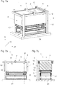
- FIGS. 6a, 6b and 6c show the state of the device 1 immediately after the beginning of the printing operation. In this case, a few layers of the particulate material 4 have already been applied and solidified at locally predetermined areas and connected together.
- the locally predetermined areas are approached by the print head 7 based on computer data.
- FIGS. 7a-7c show the device 1 after completion of printing. Schematically indicated is a manufactured three-dimensional component 2, which consists in the hatched area of solidified and interconnected particulate material. The three-dimensional component 2 is surrounded by unconsolidated loose particulate material 4.
- the coupling between the limiting device 12 and the printing platform 3 is restored.
- the coupling between the limiting device 12 and the printing frame 5 is canceled.
- the printing frame 5 is moved one piece up, so that the arrangement of the transport device 13, the printing platform 3 and the Clamping device 12 can be moved out of the device 1, without the limiting device 12 collides with the pressure frame 5.
- At least the printing platform 3 together with the limiting device 12 and the printed interior is subsequently fed to at least one unpacking station. There, the coupling between the limiting device 12 and the printing platform 3 is released and the limiting device 12 in the vertical direction moved up or down. In this case, a large part of the loose particulate material 4 will automatically fall off the printing platform 3. What remains is the manufactured three-dimensional component 2 for the construction industry.
Landscapes
- Engineering & Computer Science (AREA)
- Chemical & Material Sciences (AREA)
- Materials Engineering (AREA)
- Manufacturing & Machinery (AREA)
- Mechanical Engineering (AREA)
- Physics & Mathematics (AREA)
- Optics & Photonics (AREA)
- Architecture (AREA)
- Ceramic Engineering (AREA)
- Electromagnetism (AREA)
- Civil Engineering (AREA)
- Structural Engineering (AREA)
Description
Die Erfindung betrifft eine Vorrichtung zur Herstellung wenigstens eines dreidimensionalen Bauteils für die Bauindustrie aus einer Mehrzahl von auf einer Druckplattform übereinander angeordneter Schichten aus Partikelmaterial, die in örtlich vorbestimmten Bereichen verfestigt und miteinander zum wenigstens einen dreidimensionalen Bauteil verbunden sind, umfassend wenigstens einen Druckrahmen, an welchem wenigstens eine Beschichtungsvorrichtung zur schichtweisen Auftragung des Partikelmaterials auf der Druckplattform und wenigstens ein Druckkopf zur Abgabe wenigstens eines Bindemittels an den örtlich vorbestimmten Bereichen verfahrbar gelagert sind, und ein Gestell, an welchem der Druckrahmen in Gebrauchslage der Vorrichtung zumindest in vertikaler Richtung verstellbar gelagert ist. Die Erfindung betrifft weiterhin ein Verfahren zum Betrieb einer solchen Vorrichtung.The invention relates to a device for producing at least one three-dimensional component for the construction industry from a plurality of layers of particulate material stacked on a printing platform, solidified in locally predetermined regions and connected to each other at least one three-dimensional component comprising at least one printing frame on which at least one coating device for layered application of the particulate material on the printing platform and at least one print head for delivering at least one binder to the locally predetermined areas are movably mounted, and a frame to which the printing frame is mounted adjustable in the position of use of the device at least in the vertical direction. The invention further relates to a method for operating such a device.
Die gegenständliche Erfindung betrifft das technische Gebiet des 3D-Drucks in der Bauindustrie. Diesbezüglich werden im Wesentlichen drei Prozesstypen voneinander unterschieden, wobei zwei dieser Prozesstypen, nämlich das "Contour Crafting" und das "Concrete Printing" sehr verwandt sind und Prozesse definieren, in denen ein viskoses Betongemisch durch Düsen in situ verspritzt wird und selbst aushärtet.The subject invention relates to the technical field of 3D printing in the construction industry. In this respect, essentially three types of processes are distinguished from each other, two of these types of processes, namely "Contour Crafting" and "Concrete Printing" are very related and define processes in which a viscous concrete mix is sprayed through nozzles in situ and cures itself.
Daneben unterscheidet man als dritten Prozesstyp 3D-Druck-Verfahren auf Basis pulverförmiger Werkstoffe, die unter dem Einfluss zumindest eines Binders zu einem dreidimensionalen Bauteil verbunden werden. Zumeist wird hierzu ein Partikelmaterial schichtweise aufgetragen und in örtlich vorbestimmten Bereichen durch Abgabe wenigstens eines Bindemittels verfestigt und miteinander verbunden.In addition, a distinction is made as a third process type 3D printing process based on powdery materials, which are connected under the influence of at least one binder to a three-dimensional component. In most cases, a particulate material is applied in layers and solidified in locally predetermined areas by dispensing at least one binder and bonded together.
Dieses Verfahren kommt auf anderen technischen Gebieten bereits seit längerer Zeit zum Einsatz, wobei die Druckplattform in der Regel während des Druckprozesses nach unten verfahren wird bis der Druckprozess abgeschlossen ist. Zur seitlichen Begrenzung des schichtweise aufgetragenen Partikelmaterials werden beispielsweise Seitenwände abgerollt, wie dies in der
Nun könnte man sich überlegen, die Druckplattform während des Druckprozesses nicht zu bewegen und stattdessen den Druckrahmen zu verfahren. Hierzu gibt es auf anderen technischen Gebieten bereits ebenfalls Lösungen. Beispielsweise beschreibt die
Die
Diese Aufgabe wird gelöst durch die Merkmale der unabhängigen Ansprüche 1 bzw. 12.This object is achieved by the features of
Es ist also bei der Vorrichtung zur Herstellung wenigstens eines dreidimensionalen Bauteils für die Bauindustrie vorgesehen, dass eine Koppelungsvorrichtung vorgesehen ist, mit welcher eine Begrenzungsvorrichtung zur seitlichen Begrenzung des Partikelmaterials mit dem wenigstens einen Druckrahmen lösbar koppelbar ist, so dass die Begrenzungsvorrichtung mit dem Druckrahmen bei einer Verstellung zumindest in die vertikale Richtung mitbewegbar ist.It is therefore provided in the apparatus for producing at least one three-dimensional component for the construction industry, that a coupling device is provided, with which a limiting device for lateral delimitation of the particulate material with the at least one pressure frame is detachably coupled, so that the limiting device with the printing frame at a Adjustment is mitbewegbar at least in the vertical direction.
Auf diese Weise ist es möglich, eine wiederverwendbare Begrenzungsvorrichtung zur seitlichen Begrenzung des Partikelmaterials während des Druckvorgangs mit dem wenigstens einen Druckrahmen zu koppeln und den Druckrahmen gegenüber einer während des Druckprozesses feststehenden Druckplattform in vertikaler Richtung zu verstellen und dabei gleichzeitig eine optimale seitliche Begrenzung des Partikelmaterials sicherzustellen.In this way, it is possible to couple a reusable limiting device for laterally limiting the particle material during the printing process with the at least one printing frame and to adjust the printing frame in the vertical direction relative to a printing platform fixed during the printing process and at the same time to ensure an optimal lateral boundary of the particle material ,
Ein großer Vorteil besteht darin, dass die Druckplattform samt der Begrenzungsvorrichtung und dem wenigstens einen hergestellten dreidimensionalen Bauteil von dem Druckrahmen entfernt und zu einem Entformungsbereich transportiert werden kann, an welchem die Entformung des wenigstens einen hergestellten dreidimensionalen Bauteils erfolgt. Bei der Entformung entweicht loses Material, welches nicht Teil des Bauteils ist. Dabei kann es zu einer ungünstigen Staubentwicklung gelangen. Würde man die Entformung unmittelbar im Bereich des Druckrahmens durchführen, so bestünde die Gefahr, dass das lose Material Bestandteile des Druckrahmens, wie z.B. den Antrieb des Druckkopfes, beschädigt. Diese Gefahr ist gänzlich gebannt, wenn die Entformung an einem separaten Ort erfolgt.A great advantage consists in that the printing platform together with the limiting device and the at least one produced three-dimensional component can be removed from the printing frame and transported to a demoulding area where the demoulding of the at least one produced three-dimensional component takes place. During demolding loose material escapes, which is not part of the component. This can lead to an unfavorable development of dust. If one were to carry out the demolding directly in the area of the printing frame, then there would be the risk that the loose material components of the printing frame, such as the drive of the print head, damaged. This danger is completely banned if demolding takes place in a separate location.
Weiterhin würde der Druckrahmen die Zugänglichkeit zu dem wenigstens einen hergestellten dreidimensionalen Bauteil erschweren. Auch dieser Nachteil kann durch die vorliegende Erfindung behoben werden.Furthermore, the printing frame would make accessibility to the at least one manufactured three-dimensional component difficult. This disadvantage can also be eliminated by the present invention.
Und schließlich bietet die Entformung an einem vom Druckrahmen separaten Ort die Möglichkeit, die Herstellung zu beschleunigen, da unmittelbar nach dem Abtransport des Pakets aus Druckplattform samt der Begrenzungsvorrichtung und dem wenigstens einen hergestellten dreidimensionalen Bauteil bereits mit dem Druck eines weiteren Bauteils auf einer neuen Druckplattform begonnen werden kann, ohne dass die Entformung abgewartet werden muss.And finally, the demolding offers at a separate location from the printing frame the ability to speed up the production, since immediately after the removal of the package of printing platform including the limiting device and the at least one manufactured three-dimensional component already started printing another component on a new printing platform without having to wait for demoulding.
Bei dem erfindungsgemäßen Verfahren zum Betrieb der erfindungsgemäßen Vorrichtung ist es vorgesehen, dass
- eine Begrenzungsvorrichtung zur seitlichen Begrenzung des Partikelmaterials mittels der hierzu vorgesehenen Koppelungsvorrichtung mit dem wenigstens einen Druckrahmen gekoppelt wird,
- der Druckrahmen samt der daran gekoppelten Begrenzungsvorrichtung auf Höhe der Druckplattform positioniert wird, und
- der Druckvorgang zur Herstellung des wenigstens eines dreidimensionalen Bauteils für die Bauindustrie durch schichtweise Auftragung des Partikelmaterials und Abgabe des wenigstens einen Bindemittels in den örtlich vorbestimmten Bereichen durchgeführt wird, wobei der Druckrahmen zumindest in die vertikale Richtung schrittweise mit einer Schrittweite, welche im Wesentlichen der Höhe der aufgetragenen Partikelmaterialschichten entspricht, angehoben wird.
- a limiting device for lateral limiting of the particulate material is coupled to the at least one pressure frame by means of the coupling device provided for this purpose,
- the printing frame, together with the limiting device coupled thereto, is positioned at the level of the printing platform, and
- the printing operation for producing the at least one three-dimensional component for the construction industry is carried out by coating the particulate material in layers and dispensing the at least one binder in the locally predetermined areas, wherein the printing frame is stepped at least in the vertical direction with a pitch substantially equal to the height of the applied particulate material layers, is raised.
Besonders vorteilhafte Ausführungsformen der erfindungsgemäßen Vorrichtung bzw. des erfindungsgemäßen Verfahren zum Betrieb der erfindungsgemäßen Vorrichtung sind in den abhängigen Ansprüchen 2-11 und 13-15 definiert.Particularly advantageous embodiments of the device according to the invention or of the method according to the invention for operating the device according to the invention are defined in the dependent claims 2-11 and 13-15.
Es ist gemäß einer bevorzugten Ausführungsform vorgesehen, dass die Koppelungsvorrichtung, mit welcher eine Begrenzungsvorrichtung zur seitlichen Begrenzung des Partikelmaterials mit dem wenigstens einen Druckrahmen lösbar koppelbar ist, und gegebenenfalls die Koppelungsvorrichtung, mit welcher die Begrenzungsvorrichtung zur seitlichen Begrenzung des Partikelmaterials mit der Druckplattform und/oder einer gegebenenfalls vorhandenen Transportvorrichtung lösbar koppelbar ist, wenigstens einen, vorzugsweise vier, Verriegelungsbolzen und korrespondierende Ausnehmungen umfasst.It is provided according to a preferred embodiment that the coupling device, with which a limiting device for lateral delimitation of the particulate material with the at least one pressure frame is releasably coupled, and optionally the coupling device with which the limiting device for lateral delimitation of the particulate material with the pressure platform and / or an optionally present transport device is releasably coupled, at least one, preferably four, locking bolt and corresponding recesses comprises.
Diese Koppelungsvorrichtungen können aber auch auf eine andere Art technisch realisiert werden. Es können beispielsweise auch lösbare Schnapp- und/oder Rastverbindungen zum Einsatz kommen. Weiterhin ist es denkbar, dass anstelle einer rein mechanischen Lösung eine elektromechanische Lösung, die auch mit einer Steuerungseinheit verbunden sein kann, zum Einsatz kommt.These coupling devices can also be technically realized in another way. For example, detachable snap-in and / or snap-in connections can also be used. Furthermore, it is conceivable that, instead of a purely mechanical solution, an electromechanical solution, which may also be connected to a control unit, is used.
Weitere Einzelheiten und Vorteile der Erfindung werden anhand der Figurenbeschreibung unter Bezugnahme auf die Zeichnungen im Folgenden näher erläutert. Darin zeigen:
- Fig. 1
- eine Transportvorrichtung in einer perspektivischen Ansicht,
- Fig. 2
- die Transportvorrichtung aus der
Figur 1 - Fig. 3
- die Anordnung aus einer Transportvorrichtung und einer Druckplattform gemäß
Fig. 2 in Kombination mit einer Begrenzungsvorrichtung zur seitlichen Begrenzung des Partikelmaterials, - Fig. 4
- eine Vorrichtung zur Herstellung wenigstens eines dreidimensionalen Bauteils für die Bauindustrie gemäß einer bevorzugten Ausführungsform,
- Fig. 5
- die Vorrichtung gemäß
Fig. 4 mit einer darin angeordneten Transportvorrichtung, einer Druckplattform und einer Begrenzungsvorrichtung, - Fig. 6a-6c
- die Anordnung gemäß
Fig. 5 zu Beginn des Druckvorgangs und zwar in einer perspektivischen Ansicht (Fig. 6a ), in einer Seitenansicht (Fig. 6b ) und in einer Querschnittsansicht entlang der in derFig. 6b eingezeichneten Schnittebene 31 (Fig. 6c ) und - Fig. 7a-7c
- die Anordnung gemäß den
Figuren 6a-6c nach Abschluss des Druckvorgangs.
- Fig. 1
- a transport device in a perspective view,
- Fig. 2
- the transport device from the
FIG. 1 with a printing platform arranged thereon, - Fig. 3
- the arrangement of a transport device and a printing platform according to
Fig. 2 in combination with a limiting device for the lateral limitation of the particulate material, - Fig. 4
- a device for producing at least one three-dimensional component for the construction industry according to a preferred embodiment,
- Fig. 5
- the device according to
Fig. 4 with a transport device arranged therein, a printing platform and a limiting device, - Fig. 6a-6c
- the arrangement according to
Fig. 5 at the beginning of the printing process and in a perspective view (Fig. 6a ), in a side view (Fig. 6b ) and in a cross-sectional view along in theFig. 6b drawn cutting plane 31 (Fig. 6c ) and - Fig. 7a-7c
- the arrangement according to the
Figures 6a-6c after completing the printing process.
Der Rahmen 16 ist als rechteckiger Rahmen mit einer zentralen Öffnung ausgebildet und im Wesentlichen aus Stahl gefertigt. Im Bereich der vier Ecken des Rahmens 16 sind Vorsprünge 14 ausgebildet. Diese dienen zur verschiebesicheren Lagerung der Druckplattform 3 auf der Transportvorrichtung 13. Dazu greifen die Vorsprünge 14 in korrespondierende Ausnehmungen 15, welche in auf der Unterseite der Druckplattform 3 angeordnete Füße ausgebildet sind, ein.The
Die Begrenzungsvorrichtung 12 weist eine Höhe 23 von 1,5 m, eine Breite 24 von 4 m und eine Tiefe 25 von 2 m auf. Damit ergibt sich ein Druckvolumen von 12 m3. Im Bedarfsfall können die Dimensionen der Begrenzungsvorrichtung 12 auch an größere oder kleinere Druckvolumina angepasst werden.The limiting
Um die Anordnung aus der Transportvorrichtung 13, der Druckplattform 3 und der Begrenzungsvorrichtung 12 in ihrer Gesamtheit bewegen zu können, ohne dass es dabei zu einer Relativbewegung dieser drei Komponenten untereinander kommt, ist eine Kopplungsvorrichtung 10, 11 vorgesehen, mit welcher die Begrenzungsvorrichtung 12 mit der Druckplattform 3 lösbar koppelbar ist. Konkret wird die Kopplungsvorrichtung gebildet aus vier Verriegelungsbolzen 10, welche in korrespondierenden Ausnehmungen 11 eingreifen, wobei diese korrespondierenden Ausnehmungen 11 sowohl in der Begrenzungsvorrichtung 12 als auch in der Druckplattform 3 angeordnet sind. Zur lösbaren Kopplung der Begrenzungsvorrichtung 12 mit der Druckplattform 3 werden Ausnehmungen 11 verwendet, die in Gebrauchslage im unteren Bereich der Begrenzungsvorrichtung 12 ausgebildet sind. Auf den Zweck der im oberen Bereich der Begrenzungsvorrichtung 12 angeordneten Ausnehmungen 11 wird nachfolgend eingegangen.In order to move the arrangement of the
Die Vorrichtung 1 weist weiterhin eine Abstützvorrichtung 26 auf. Die Abstützvorrichtung 26 umfasst zwei voneinander beabstandete Schienen, auf denen die in
In weiterer Folge wird der Druckrahmen 5 und damit die daran gekoppelte Begrenzungsvorrichtung 12 abgesenkt und zwar so weit, dass sich der Druckkopf 7 und die Beschichtungsvorrichtunge 6 unmittelbar über der Druckplattform 3 befinden und mit dem Druckvorgang begonnen werden kann. Es bietet sich dabei an, dass die Anordnung aus der Abstützvorrichtung 26, der Druckplattform 3 und der Transportvorrichtung 13 eine Gesamthöhe 27 aufweist, welche mindestens der Höhe 23 der Begrenzungsvorrichtung 12 (vergleiche
Es sei noch darauf hingewiesen, dass die x- und y-Komponenten, welche die horizontale Ebene definieren, mit den Bezugszeichen 28 und 29 versehen sind.It should be noted that the x and y components defining the horizontal plane are designated by
Es wird nun mit dem Druckvorgang begonnen. Dabei wird mittels der Beschichtungsvorrichtunge 6 schichtweise ein Partikelmaterial 4 aufgetragen und dieses mittels wenigstens eines Bindemittels und gegebenenfalls eines Härtemittels an örtlich vorbestimmten Bereichen verfestigt und miteinander verbunden. Das wenigstens eine Bindemittel wird dabei mit Hilfe des Druckkopfs 7 an den örtlich vorbestimmten Bereichen versprüht. Nachdem auf diese Weise eine Schicht mit einer bestimmten Schichtdicke aufgetragen und bearbeitet wurde, wird der Druckrahmen 5 in vertikaler Richtung 9 um einen bestimmten Weg 34 angehoben. Dieser Weg 34 definiert die Dicke der nachfolgend aufgetragenen Schicht. Da die Begrenzungsvorrichtung 12 mit dem Druckrahmen 5 gekoppelt ist, wird die Begrenzungsvorrichtung 12 zwangsweise um denselben Weg 34 in vertikaler Richtung 9 mitbewegt. Diese Vorgänge wiederholen sich so lange, bis das gesamte zur Verfügung stehende Druckvolumen ausgereizt ist bzw. bis das wenigstens eine herzustellende dreidimensionale Bauteil fertig gestellt ist.It will now start printing. In this case, a
Die
Die örtlich vorbestimmten Bereiche werden basierend auf Computerdaten von dem Druckkopf 7 angefahren.The locally predetermined areas are approached by the
Die
Zur Ausformung des dreidimensionalen Bauteils 2 wird die Kopplung zwischen der Begrenzungsvorrichtung 12 und der Druckplattform 3 wieder hergestellt. Die Kopplung zwischen der Begrenzungsvorrichtung 12 und dem Druckrahmen 5 wird aufgehoben. Der Druckrahmen 5 wird ein Stück nach oben bewegt, sodass die Anordnung aus der Transportvorrichtung 13, der Druckplattform 3 und der Begrenzungsvorrichtung 12 aus der Vorrichtung 1 herausgefahren werden kann, ohne dass die Begrenzungsvorrichtung 12 mit dem Druckrahmen 5 kollidiert.For the formation of the three-
Zumindest die Druckplattform 3 zusammen mit der Begrenzungsvorrichtung 12 und dem gedruckten Innenleben wird in weiterer Folge zumindest einer Entpackungsstation zugeführt. Dort wird die Kopplung zwischen der Begrenzungsvorrichtung 12 und der Druckplattform 3 aufgehoben und die Begrenzungsvorrichtung 12 in vertikaler Richtung nach oben oder unten verfahren. Dabei wird ein großer Teil des losen Partikelmaterials 4 von selbst von der Druckplattform 3 herabfallen. Übrig bleibt das hergestellte dreidimensionale Bauteil 2 für die Bauindustrie.At least the
Claims (15)
- Apparatus (1) for producing at least one 3-dimensional component (2) for the building industry from a plurality of layers of particulate material (4) which are arranged in mutually superposed relationship on a printing platform (3) and which are solidified in locally predetermined regions and are connected together to form the at least one 3-dimensional component (2), including at least one printing frame (5) on which at least one coating device (6) for layer-wise application of the particulate material on the printing platform (3) and at least one printing head (7) for the delivery of at least one binding agent at the locally predetermined regions are displaceably mounted, and a frame (8) on which the printing frame (5) is mounted displaceably at least in the vertical direction (9) in the position of use of the apparatus (1), wherein there is provided a coupling device (10, 11) with which a delimiting device (12) for laterally delimiting the particulate material (4) can be releasably coupled to the at least one printing frame (5) so that the delimiting device (12) is moveable with the printing frame (5) upon a displacement at least in the vertical direction (9).
- Apparatus (1) according to claim 1 wherein there is provided a transport device (13) on which the printing platform (3) is arranged, preferably wherein the printing platform (3) is mounted on the transport device (13) non-displaceably by way of projections (14) and corresponding recesses (15).
- Apparatus (1) according to claim 2 wherein the transport device (13) is formed substantially from a frame (16) on which rolling bodies (17) are arranged for supporting the transport device (13) on a support surface.
- Apparatus (1) according to claim 3 wherein the rolling bodies (17) are drivable preferably by means of electric motors (18).
- Apparatus (1) according to one of claims 1 to 4 wherein there is provided a further coupling device (10, 11) with which the delimiting device (12) for laterally delimiting the particulate material can be coupled releasably to the printing platform (3) and/or to a transport device (13) which is possibly provided.
- Apparatus (1) according to one of claims 1 to 5 wherein the delimiting device (12) is formed substantially from four walls (19, 20, 21, 22) arranged at a right angle to each other.
- Apparatus (1) according to claim 6 wherein the walls (19, 20, 21, 22) of the delimiting device (12)- substantially comprise hollow profile members, preferably of aluminium, and/or- are of a flexurally stiff configuration, and/or- have a smooth surface with a low coefficient of friction to avoid adhesion of the particulate material (4).
- Apparatus (1) according to one of claims 1 to 7 wherein the delimiting device (12) is- of a height (23) of 1 to 2 m, preferably 1.5 m, and/or- is of a width (24) of 3 to 5 m, preferably 4 m, and/or- is of a depth (25) of 1 to 3 m, preferably 2 m.
- Apparatus (1) according to one of claims 1 to 8 wherein there is provided a support device (21), preferably in rail form, for supporting the printing platform (3) and a transport device (13) which is possibly provided.
- Apparatus (1) according to claim 9 wherein the arrangement comprising the support device (26), the printing platform (3) and a transport device (13) which is possibly provided is of a total height (27) which corresponds at least to the height (23) of the delimiting device (12).
- Apparatus (1) according to one of claims 1 to 10 wherein the coupling device (10, 11) with which a delimiting device (12) for laterally delimiting the particulate material (4) can be releasably coupled to the at least one printing frame (5) and optionally the coupling device (10, 11) with which the delimiting device (12) for laterally delimiting the particulate material (4) can be releasably coupled to the printing platform (3) and/or a transport device (13) which is possibly provided includes at least one and preferably four locking pins (10) and corresponding openings (11).
- A method of operating an apparatus (1) according to one of claims 1 to 11 wherein- the delimiting device (12) for laterally delimiting the particulate material (4) is coupled to the at least one printing frame (5) by means of the coupling device (10, 11) provided for that purpose,- the printing frame (5) together with the delimiting device (12) coupled thereto is positioned at the height of the printing platform (3), and- the printing operation for producing the at least one 3-dimensional component (2) for the building industry is performed by layer-wise application of the particulate material (4) and delivery of the at least one binding agent in the locally predetermined regions, wherein the printing frame (5) is lifted at least in the vertical direction (9) in stepwise manner with a stepping dimension substantially corresponding to the height of the applied particulate material layers.
- A method according to claim 12 wherein the delimiting device (12) is uncoupled from the at least one printing frame (5) after conclusion of the printing operation.
- A method according to claim 12 or claim 13 wherein the printing platform (3) and the delimiting device (2) are positioned in the apparatus (1) at the beginning of the method and are removed from the apparatus (1) again after conclusion of the printing operation.
- A method according to one of claims 12 to 14 wherein the delimiting device (8) is coupled to the printing platform (3) and/or a transport device (13) which is possibly provided by means of the coupling device (10, 11) provided for that purpose at the beginning of the method and said coupling is released.
Priority Applications (1)
| Application Number | Priority Date | Filing Date | Title |
|---|---|---|---|
| PL17177714T PL3260272T3 (en) | 2016-06-23 | 2017-06-23 | Device for the production of at least one three-dimensional component for the building industry |
Applications Claiming Priority (1)
| Application Number | Priority Date | Filing Date | Title |
|---|---|---|---|
| ATA50569/2016A AT518837B1 (en) | 2016-06-23 | 2016-06-23 | Device for producing at least one three-dimensional component for the construction industry |
Publications (2)
| Publication Number | Publication Date |
|---|---|
| EP3260272A1 EP3260272A1 (en) | 2017-12-27 |
| EP3260272B1 true EP3260272B1 (en) | 2018-10-17 |
Family
ID=59215617
Family Applications (1)
| Application Number | Title | Priority Date | Filing Date |
|---|---|---|---|
| EP17177714.7A Active EP3260272B1 (en) | 2016-06-23 | 2017-06-23 | Device for the production of at least one three-dimensional component for the building industry |
Country Status (4)
| Country | Link |
|---|---|
| EP (1) | EP3260272B1 (en) |
| AT (1) | AT518837B1 (en) |
| DK (1) | DK3260272T3 (en) |
| PL (1) | PL3260272T3 (en) |
Cited By (1)
| Publication number | Priority date | Publication date | Assignee | Title |
|---|---|---|---|---|
| WO2021028797A1 (en) | 2019-08-09 | 2021-02-18 | Ing-3D Ug | Method for producing an additively manufactured product from a mineral starting material by means of direct laser sintering, and lightweight part produced by means of said method |
Families Citing this family (3)
| Publication number | Priority date | Publication date | Assignee | Title |
|---|---|---|---|---|
| AT522560B1 (en) * | 2019-05-29 | 2020-12-15 | Progress Maschinen & Automation Ag | Arrangement for producing at least one three-dimensional component for the construction industry |
| CN110406102B (en) * | 2019-08-27 | 2023-09-12 | 江苏集萃微纳自动化系统与装备技术研究所有限公司 | Can dismantle cylinder body subassembly of 3D printer |
| CN112157795A (en) * | 2020-09-22 | 2021-01-01 | 湖南汇渠建筑科技有限公司 | Assembly type building concrete pouring device based on BIM |
Family Cites Families (8)
| Publication number | Priority date | Publication date | Assignee | Title |
|---|---|---|---|---|
| US20050280185A1 (en) * | 2004-04-02 | 2005-12-22 | Z Corporation | Methods and apparatus for 3D printing |
| ITPI20050031A1 (en) * | 2005-03-22 | 2006-09-23 | Moreno Chiarugi | METHOD AND DEVICE FOR THE AUTOMATIC CONSTRUCTION OF CONGLOMERATE BUILDING STRUCTURES |
| CN101541511B (en) * | 2007-05-30 | 2011-12-21 | 松下电工株式会社 | Laminate shaping apparatus |
| ITPI20070108A1 (en) * | 2007-09-17 | 2009-03-18 | Enrico Dini | PERFECTED METHOD FOR THE AUTOMATIC CONSTRUCTION OF CONGLOMERATE STRUCTURES |
| JP5355213B2 (en) * | 2009-05-18 | 2013-11-27 | パナソニック株式会社 | Laminate modeling equipment for modeling three-dimensional shaped objects |
| DE102010013733A1 (en) * | 2010-03-31 | 2011-10-06 | Voxeljet Technology Gmbh | Device for producing three-dimensional models |
| US9149870B2 (en) * | 2012-09-14 | 2015-10-06 | Aerojet Rocketdyne Of De, Inc. | Additive manufacturing chamber with reduced load |
| JP6448003B2 (en) * | 2014-03-19 | 2019-01-09 | シーメット株式会社 | 3D modeling equipment modeling tank |
-
2016
- 2016-06-23 AT ATA50569/2016A patent/AT518837B1/en active
-
2017
- 2017-06-23 EP EP17177714.7A patent/EP3260272B1/en active Active
- 2017-06-23 DK DK17177714.7T patent/DK3260272T3/en active
- 2017-06-23 PL PL17177714T patent/PL3260272T3/en unknown
Non-Patent Citations (1)
| Title |
|---|
| None * |
Cited By (1)
| Publication number | Priority date | Publication date | Assignee | Title |
|---|---|---|---|---|
| WO2021028797A1 (en) | 2019-08-09 | 2021-02-18 | Ing-3D Ug | Method for producing an additively manufactured product from a mineral starting material by means of direct laser sintering, and lightweight part produced by means of said method |
Also Published As
| Publication number | Publication date |
|---|---|
| EP3260272A1 (en) | 2017-12-27 |
| AT518837A1 (en) | 2018-01-15 |
| DK3260272T3 (en) | 2019-02-18 |
| PL3260272T3 (en) | 2019-05-31 |
| AT518837B1 (en) | 2018-06-15 |
Similar Documents
| Publication | Publication Date | Title |
|---|---|---|
| EP1563928B1 (en) | Apparatus for a stratified construction of models | |
| EP3077181B1 (en) | Building container with movable side walls | |
| EP3351384B1 (en) | 3d printer, 3d printer assembly and generative production method | |
| EP2552674B1 (en) | Device for producing three-dimensional models | |
| EP3260272B1 (en) | Device for the production of at least one three-dimensional component for the building industry | |
| EP1872928B1 (en) | Method for building up three-dimensional parts | |
| EP2391499B1 (en) | Rapid prototyping system comprising a construction box | |
| EP2822753B1 (en) | Method and device for producing three-dimensional models | |
| EP3036087B1 (en) | Coating arrangement for a 3d printer | |
| EP3966019B1 (en) | Construction box system for a 3d printer, 3d printer, 3d printer system, use of the construction box system and 3d printing method | |
| EP1605101B1 (en) | Process and apparatus for the fabrication of a multilayered concrete plate | |
| EP3787866B1 (en) | System and method for flexibly forming a casting mold for manufacturing a model casting | |
| AT522560B1 (en) | Arrangement for producing at least one three-dimensional component for the construction industry | |
| EP3749470A1 (en) | 3d printer and generative manufacturing process | |
| EP0098271B1 (en) | Device for changing model plates in molding machines | |
| DE1683809C3 (en) | Compression press for making panels | |
| DE102022126586A1 (en) | 3D printing processes and 3D printers | |
| EP0515884A1 (en) | Apparatus for coating a machine bed of a machine tool, especially a grinding machine | |
| DD251960A1 (en) | DEVICE FOR FEEDING, STACKING AND TRANSFERRING OBJECTS BETWEEN SUPPLEMENTS |
Legal Events
| Date | Code | Title | Description |
|---|---|---|---|
| PUAI | Public reference made under article 153(3) epc to a published international application that has entered the european phase |
Free format text: ORIGINAL CODE: 0009012 |
|
| STAA | Information on the status of an ep patent application or granted ep patent |
Free format text: STATUS: THE APPLICATION HAS BEEN PUBLISHED |
|
| AK | Designated contracting states |
Kind code of ref document: A1 Designated state(s): AL AT BE BG CH CY CZ DE DK EE ES FI FR GB GR HR HU IE IS IT LI LT LU LV MC MK MT NL NO PL PT RO RS SE SI SK SM TR |
|
| AX | Request for extension of the european patent |
Extension state: BA ME |
|
| STAA | Information on the status of an ep patent application or granted ep patent |
Free format text: STATUS: REQUEST FOR EXAMINATION WAS MADE |
|
| 17P | Request for examination filed |
Effective date: 20180119 |
|
| RBV | Designated contracting states (corrected) |
Designated state(s): AL AT BE BG CH CY CZ DE DK EE ES FI FR GB GR HR HU IE IS IT LI LT LU LV MC MK MT NL NO PL PT RO RS SE SI SK SM TR |
|
| GRAP | Despatch of communication of intention to grant a patent |
Free format text: ORIGINAL CODE: EPIDOSNIGR1 |
|
| STAA | Information on the status of an ep patent application or granted ep patent |
Free format text: STATUS: GRANT OF PATENT IS INTENDED |
|
| RIC1 | Information provided on ipc code assigned before grant |
Ipc: B29C 64/255 20170101ALI20180221BHEP Ipc: B29C 64/259 20170101ALI20180221BHEP Ipc: B29C 64/165 20170101AFI20180221BHEP |
|
| INTG | Intention to grant announced |
Effective date: 20180321 |
|
| GRAS | Grant fee paid |
Free format text: ORIGINAL CODE: EPIDOSNIGR3 |
|
| GRAA | (expected) grant |
Free format text: ORIGINAL CODE: 0009210 |
|
| STAA | Information on the status of an ep patent application or granted ep patent |
Free format text: STATUS: THE PATENT HAS BEEN GRANTED |
|
| AK | Designated contracting states |
Kind code of ref document: B1 Designated state(s): AL AT BE BG CH CY CZ DE DK EE ES FI FR GB GR HR HU IE IS IT LI LT LU LV MC MK MT NL NO PL PT RO RS SE SI SK SM TR |
|
| REG | Reference to a national code |
Ref country code: GB Ref legal event code: FG4D Free format text: NOT ENGLISH |
|
| REG | Reference to a national code |
Ref country code: CH Ref legal event code: EP |
|
| REG | Reference to a national code |
Ref country code: IE Ref legal event code: FG4D Free format text: LANGUAGE OF EP DOCUMENT: GERMAN |
|
| REG | Reference to a national code |
Ref country code: DE Ref legal event code: R096 Ref document number: 502017000256 Country of ref document: DE Ref country code: AT Ref legal event code: REF Ref document number: 1053473 Country of ref document: AT Kind code of ref document: T Effective date: 20181115 |
|
| REG | Reference to a national code |
Ref country code: CH Ref legal event code: NV Representative=s name: ISLER AND PEDRAZZINI AG, CH |
|
| REG | Reference to a national code |
Ref country code: NL Ref legal event code: FP |
|
| REG | Reference to a national code |
Ref country code: DK Ref legal event code: T3 Effective date: 20190211 |
|
| REG | Reference to a national code |
Ref country code: SE Ref legal event code: TRGR |
|
| REG | Reference to a national code |
Ref country code: LT Ref legal event code: MG4D |
|
| PG25 | Lapsed in a contracting state [announced via postgrant information from national office to epo] |
Ref country code: IS Free format text: LAPSE BECAUSE OF FAILURE TO SUBMIT A TRANSLATION OF THE DESCRIPTION OR TO PAY THE FEE WITHIN THE PRESCRIBED TIME-LIMIT Effective date: 20190217 Ref country code: FI Free format text: LAPSE BECAUSE OF FAILURE TO SUBMIT A TRANSLATION OF THE DESCRIPTION OR TO PAY THE FEE WITHIN THE PRESCRIBED TIME-LIMIT Effective date: 20181017 Ref country code: HR Free format text: LAPSE BECAUSE OF FAILURE TO SUBMIT A TRANSLATION OF THE DESCRIPTION OR TO PAY THE FEE WITHIN THE PRESCRIBED TIME-LIMIT Effective date: 20181017 Ref country code: LT Free format text: LAPSE BECAUSE OF FAILURE TO SUBMIT A TRANSLATION OF THE DESCRIPTION OR TO PAY THE FEE WITHIN THE PRESCRIBED TIME-LIMIT Effective date: 20181017 Ref country code: LV Free format text: LAPSE BECAUSE OF FAILURE TO SUBMIT A TRANSLATION OF THE DESCRIPTION OR TO PAY THE FEE WITHIN THE PRESCRIBED TIME-LIMIT Effective date: 20181017 Ref country code: NO Free format text: LAPSE BECAUSE OF FAILURE TO SUBMIT A TRANSLATION OF THE DESCRIPTION OR TO PAY THE FEE WITHIN THE PRESCRIBED TIME-LIMIT Effective date: 20190117 Ref country code: ES Free format text: LAPSE BECAUSE OF FAILURE TO SUBMIT A TRANSLATION OF THE DESCRIPTION OR TO PAY THE FEE WITHIN THE PRESCRIBED TIME-LIMIT Effective date: 20181017 Ref country code: BG Free format text: LAPSE BECAUSE OF FAILURE TO SUBMIT A TRANSLATION OF THE DESCRIPTION OR TO PAY THE FEE WITHIN THE PRESCRIBED TIME-LIMIT Effective date: 20190117 |
|
| PG25 | Lapsed in a contracting state [announced via postgrant information from national office to epo] |
Ref country code: PT Free format text: LAPSE BECAUSE OF FAILURE TO SUBMIT A TRANSLATION OF THE DESCRIPTION OR TO PAY THE FEE WITHIN THE PRESCRIBED TIME-LIMIT Effective date: 20190217 Ref country code: AL Free format text: LAPSE BECAUSE OF FAILURE TO SUBMIT A TRANSLATION OF THE DESCRIPTION OR TO PAY THE FEE WITHIN THE PRESCRIBED TIME-LIMIT Effective date: 20181017 Ref country code: GR Free format text: LAPSE BECAUSE OF FAILURE TO SUBMIT A TRANSLATION OF THE DESCRIPTION OR TO PAY THE FEE WITHIN THE PRESCRIBED TIME-LIMIT Effective date: 20190118 Ref country code: RS Free format text: LAPSE BECAUSE OF FAILURE TO SUBMIT A TRANSLATION OF THE DESCRIPTION OR TO PAY THE FEE WITHIN THE PRESCRIBED TIME-LIMIT Effective date: 20181017 |
|
| REG | Reference to a national code |
Ref country code: DE Ref legal event code: R097 Ref document number: 502017000256 Country of ref document: DE |
|
| PG25 | Lapsed in a contracting state [announced via postgrant information from national office to epo] |
Ref country code: CZ Free format text: LAPSE BECAUSE OF FAILURE TO SUBMIT A TRANSLATION OF THE DESCRIPTION OR TO PAY THE FEE WITHIN THE PRESCRIBED TIME-LIMIT Effective date: 20181017 |
|
| PLBE | No opposition filed within time limit |
Free format text: ORIGINAL CODE: 0009261 |
|
| STAA | Information on the status of an ep patent application or granted ep patent |
Free format text: STATUS: NO OPPOSITION FILED WITHIN TIME LIMIT |
|
| PG25 | Lapsed in a contracting state [announced via postgrant information from national office to epo] |
Ref country code: RO Free format text: LAPSE BECAUSE OF FAILURE TO SUBMIT A TRANSLATION OF THE DESCRIPTION OR TO PAY THE FEE WITHIN THE PRESCRIBED TIME-LIMIT Effective date: 20181017 Ref country code: EE Free format text: LAPSE BECAUSE OF FAILURE TO SUBMIT A TRANSLATION OF THE DESCRIPTION OR TO PAY THE FEE WITHIN THE PRESCRIBED TIME-LIMIT Effective date: 20181017 Ref country code: SM Free format text: LAPSE BECAUSE OF FAILURE TO SUBMIT A TRANSLATION OF THE DESCRIPTION OR TO PAY THE FEE WITHIN THE PRESCRIBED TIME-LIMIT Effective date: 20181017 Ref country code: SK Free format text: LAPSE BECAUSE OF FAILURE TO SUBMIT A TRANSLATION OF THE DESCRIPTION OR TO PAY THE FEE WITHIN THE PRESCRIBED TIME-LIMIT Effective date: 20181017 |
|
| 26N | No opposition filed |
Effective date: 20190718 |
|
| PG25 | Lapsed in a contracting state [announced via postgrant information from national office to epo] |
Ref country code: SI Free format text: LAPSE BECAUSE OF FAILURE TO SUBMIT A TRANSLATION OF THE DESCRIPTION OR TO PAY THE FEE WITHIN THE PRESCRIBED TIME-LIMIT Effective date: 20181017 |
|
| PG25 | Lapsed in a contracting state [announced via postgrant information from national office to epo] |
Ref country code: MC Free format text: LAPSE BECAUSE OF FAILURE TO SUBMIT A TRANSLATION OF THE DESCRIPTION OR TO PAY THE FEE WITHIN THE PRESCRIBED TIME-LIMIT Effective date: 20181017 |
|
| PG25 | Lapsed in a contracting state [announced via postgrant information from national office to epo] |
Ref country code: TR Free format text: LAPSE BECAUSE OF FAILURE TO SUBMIT A TRANSLATION OF THE DESCRIPTION OR TO PAY THE FEE WITHIN THE PRESCRIBED TIME-LIMIT Effective date: 20181017 |
|
| PG25 | Lapsed in a contracting state [announced via postgrant information from national office to epo] |
Ref country code: IE Free format text: LAPSE BECAUSE OF NON-PAYMENT OF DUE FEES Effective date: 20190623 |
|
| PG25 | Lapsed in a contracting state [announced via postgrant information from national office to epo] |
Ref country code: LU Free format text: LAPSE BECAUSE OF NON-PAYMENT OF DUE FEES Effective date: 20190623 |
|
| PG25 | Lapsed in a contracting state [announced via postgrant information from national office to epo] |
Ref country code: CY Free format text: LAPSE BECAUSE OF FAILURE TO SUBMIT A TRANSLATION OF THE DESCRIPTION OR TO PAY THE FEE WITHIN THE PRESCRIBED TIME-LIMIT Effective date: 20181017 |
|
| PG25 | Lapsed in a contracting state [announced via postgrant information from national office to epo] |
Ref country code: MT Free format text: LAPSE BECAUSE OF FAILURE TO SUBMIT A TRANSLATION OF THE DESCRIPTION OR TO PAY THE FEE WITHIN THE PRESCRIBED TIME-LIMIT Effective date: 20181017 Ref country code: HU Free format text: LAPSE BECAUSE OF FAILURE TO SUBMIT A TRANSLATION OF THE DESCRIPTION OR TO PAY THE FEE WITHIN THE PRESCRIBED TIME-LIMIT; INVALID AB INITIO Effective date: 20170623 |
|
| GBPC | Gb: european patent ceased through non-payment of renewal fee |
Effective date: 20210623 |
|
| PG25 | Lapsed in a contracting state [announced via postgrant information from national office to epo] |
Ref country code: GB Free format text: LAPSE BECAUSE OF NON-PAYMENT OF DUE FEES Effective date: 20210623 |
|
| PG25 | Lapsed in a contracting state [announced via postgrant information from national office to epo] |
Ref country code: MK Free format text: LAPSE BECAUSE OF FAILURE TO SUBMIT A TRANSLATION OF THE DESCRIPTION OR TO PAY THE FEE WITHIN THE PRESCRIBED TIME-LIMIT Effective date: 20181017 |
|
| PGFP | Annual fee paid to national office [announced via postgrant information from national office to epo] |
Ref country code: NL Payment date: 20230607 Year of fee payment: 7 Ref country code: FR Payment date: 20230628 Year of fee payment: 7 Ref country code: DK Payment date: 20230622 Year of fee payment: 7 Ref country code: DE Payment date: 20230626 Year of fee payment: 7 |
|
| PGFP | Annual fee paid to national office [announced via postgrant information from national office to epo] |
Ref country code: SE Payment date: 20230616 Year of fee payment: 7 Ref country code: PL Payment date: 20230524 Year of fee payment: 7 Ref country code: AT Payment date: 20230630 Year of fee payment: 7 |
|
| PGFP | Annual fee paid to national office [announced via postgrant information from national office to epo] |
Ref country code: BE Payment date: 20230607 Year of fee payment: 7 |
|
| PGFP | Annual fee paid to national office [announced via postgrant information from national office to epo] |
Ref country code: IT Payment date: 20230622 Year of fee payment: 7 Ref country code: CH Payment date: 20230702 Year of fee payment: 7 |