EP3256835B1 - Test device and method for testing a mirror - Google Patents
Test device and method for testing a mirror Download PDFInfo
- Publication number
- EP3256835B1 EP3256835B1 EP16703455.2A EP16703455A EP3256835B1 EP 3256835 B1 EP3256835 B1 EP 3256835B1 EP 16703455 A EP16703455 A EP 16703455A EP 3256835 B1 EP3256835 B1 EP 3256835B1
- Authority
- EP
- European Patent Office
- Prior art keywords
- mirror
- cgh
- test
- wave
- computer
- Prior art date
- Legal status (The legal status is an assumption and is not a legal conclusion. Google has not performed a legal analysis and makes no representation as to the accuracy of the status listed.)
- Active
Links
- 238000012360 testing method Methods 0.000 title claims description 97
- 238000000034 method Methods 0.000 title claims description 16
- 238000005286 illumination Methods 0.000 description 5
- 238000005259 measurement Methods 0.000 description 5
- 230000003287 optical effect Effects 0.000 description 4
- 239000000758 substrate Substances 0.000 description 4
- 238000009304 pastoral farming Methods 0.000 description 3
- 238000002310 reflectometry Methods 0.000 description 3
- 230000008901 benefit Effects 0.000 description 2
- 238000010586 diagram Methods 0.000 description 2
- 238000004519 manufacturing process Methods 0.000 description 2
- 238000001393 microlithography Methods 0.000 description 2
- 229920002120 photoresistant polymer Polymers 0.000 description 2
- 230000008569 process Effects 0.000 description 2
- 210000001747 pupil Anatomy 0.000 description 2
- 230000005855 radiation Effects 0.000 description 2
- XUIMIQQOPSSXEZ-UHFFFAOYSA-N Silicon Chemical compound [Si] XUIMIQQOPSSXEZ-UHFFFAOYSA-N 0.000 description 1
- 230000008859 change Effects 0.000 description 1
- 239000011248 coating agent Substances 0.000 description 1
- 238000000576 coating method Methods 0.000 description 1
- 230000001010 compromised effect Effects 0.000 description 1
- 238000012937 correction Methods 0.000 description 1
- 230000001419 dependent effect Effects 0.000 description 1
- 238000006073 displacement reaction Methods 0.000 description 1
- 210000000887 face Anatomy 0.000 description 1
- 230000005484 gravity Effects 0.000 description 1
- 238000003384 imaging method Methods 0.000 description 1
- 230000002452 interceptive effect Effects 0.000 description 1
- 239000000463 material Substances 0.000 description 1
- 230000003094 perturbing effect Effects 0.000 description 1
- 230000009467 reduction Effects 0.000 description 1
- 230000011514 reflex Effects 0.000 description 1
- 229910052710 silicon Inorganic materials 0.000 description 1
- 239000010703 silicon Substances 0.000 description 1
- 238000012546 transfer Methods 0.000 description 1
Images


Classifications
-
- G—PHYSICS
- G01—MEASURING; TESTING
- G01M—TESTING STATIC OR DYNAMIC BALANCE OF MACHINES OR STRUCTURES; TESTING OF STRUCTURES OR APPARATUS, NOT OTHERWISE PROVIDED FOR
- G01M11/00—Testing of optical apparatus; Testing structures by optical methods not otherwise provided for
- G01M11/005—Testing of reflective surfaces, e.g. mirrors
-
- G—PHYSICS
- G01—MEASURING; TESTING
- G01B—MEASURING LENGTH, THICKNESS OR SIMILAR LINEAR DIMENSIONS; MEASURING ANGLES; MEASURING AREAS; MEASURING IRREGULARITIES OF SURFACES OR CONTOURS
- G01B9/00—Measuring instruments characterised by the use of optical techniques
- G01B9/02—Interferometers
- G01B9/02034—Interferometers characterised by particularly shaped beams or wavefronts
- G01B9/02038—Shaping the wavefront, e.g. generating a spherical wavefront
-
- G—PHYSICS
- G01—MEASURING; TESTING
- G01B—MEASURING LENGTH, THICKNESS OR SIMILAR LINEAR DIMENSIONS; MEASURING ANGLES; MEASURING AREAS; MEASURING IRREGULARITIES OF SURFACES OR CONTOURS
- G01B9/00—Measuring instruments characterised by the use of optical techniques
- G01B9/02—Interferometers
- G01B9/02083—Interferometers characterised by particular signal processing and presentation
- G01B9/02085—Combining two or more images of different regions
-
- G—PHYSICS
- G01—MEASURING; TESTING
- G01B—MEASURING LENGTH, THICKNESS OR SIMILAR LINEAR DIMENSIONS; MEASURING ANGLES; MEASURING AREAS; MEASURING IRREGULARITIES OF SURFACES OR CONTOURS
- G01B9/00—Measuring instruments characterised by the use of optical techniques
- G01B9/02—Interferometers
- G01B9/021—Interferometers using holographic techniques
-
- G—PHYSICS
- G01—MEASURING; TESTING
- G01M—TESTING STATIC OR DYNAMIC BALANCE OF MACHINES OR STRUCTURES; TESTING OF STRUCTURES OR APPARATUS, NOT OTHERWISE PROVIDED FOR
- G01M11/00—Testing of optical apparatus; Testing structures by optical methods not otherwise provided for
- G01M11/02—Testing optical properties
- G01M11/0242—Testing optical properties by measuring geometrical properties or aberrations
- G01M11/0271—Testing optical properties by measuring geometrical properties or aberrations by using interferometric methods
-
- G—PHYSICS
- G03—PHOTOGRAPHY; CINEMATOGRAPHY; ANALOGOUS TECHNIQUES USING WAVES OTHER THAN OPTICAL WAVES; ELECTROGRAPHY; HOLOGRAPHY
- G03F—PHOTOMECHANICAL PRODUCTION OF TEXTURED OR PATTERNED SURFACES, e.g. FOR PRINTING, FOR PROCESSING OF SEMICONDUCTOR DEVICES; MATERIALS THEREFOR; ORIGINALS THEREFOR; APPARATUS SPECIALLY ADAPTED THEREFOR
- G03F7/00—Photomechanical, e.g. photolithographic, production of textured or patterned surfaces, e.g. printing surfaces; Materials therefor, e.g. comprising photoresists; Apparatus specially adapted therefor
- G03F7/70—Microphotolithographic exposure; Apparatus therefor
- G03F7/70483—Information management; Active and passive control; Testing; Wafer monitoring, e.g. pattern monitoring
- G03F7/70591—Testing optical components
- G03F7/706—Aberration measurement
Definitions
- the invention relates to a test apparatus and a method for testing a mirror, in particular a mirror of a microlithographic projection exposure apparatus.
- Microlithography is used to fabricate microstructured devices such as integrated circuits or LCDs.
- the microlithography process is carried out in a so-called projection exposure apparatus which has an illumination device and a projection objective.
- NA image-side numerical aperture
- NA image-side numerical aperture
- CGH computer-generated holograms
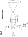
- Fig. 5 shows first a schematic representation for explaining a possible functional principle of a conventional interferometric test arrangement for testing a mirror 501.
- an interferogram is produced between reference light (reference wave) reflected at a reference surface 510 ("Fizeau plate") and a measuring light reflected at the mirror 501 (test wave). generated.
- the measurement light is formed by a computer-generated hologram (CGH) 520 into an aspherical wavefront, which corresponds mathematically exactly to the "test object shape” (ie the shape of the relevant mirror 501) at a desired distance.
- CGH computer-generated hologram
- DE 10 2012 217 800 A1 discloses, inter alia, a diffractive optical element having a substrate and a diffractive pattern disposed thereon and configured to convert an irradiated planar or spherical input wave into at least four separate output waves.
- a diffractive optical element having a substrate and a diffractive pattern disposed thereon and configured to convert an irradiated planar or spherical input wave into at least four separate output waves.
- at least three further output shafts are generated, which are flat or spherical, which makes it possible, inter alia, to measure the diffractive optical element for production errors.
- DE 10 2008 048 844 A1 discloses, inter alia, a method for measuring a surface of an object, wherein a variable light shaper comprises two arranged in a beam path of the measuring light diffraction grating, wherein displacing the surface of the object and displacing the two diffraction gratings relative to each other different parts of the surface of the object with measuring light which the variable light former has interspersed, illuminated.
- US 2012/0170038 A1 discloses, inter alia, a device for inspecting a mirror, wherein an illumination beam F2, which extends over a computer-generated hologram (CGH) comprising optical compensator, is brought to reflect on a partial surface of the surface of the mirror under test with a reference beam F1 to overlap.
- CGH computer-generated hologram
- successive photographic images of the entire mirror surface are produced by translational displacement of the arrangement to respectively different sub-areas of the mirror.
- a test device for testing a mirror, in particular a mirror of a microlithographic projection exposure apparatus
- the test apparatus comprises a computer-generated hologram (CGH) and wherein an examination of at least a partial surface of the mirror by interferometric superposition of a hologram generated by this computer on the mirror guided test wave and a reference wave is feasible
- the computer-generated hologram is designed so that during operation of the device, a first test wave for testing a first partial surface of the mirror by interferometric superposition with a reference wave in a first position of the mirror and at least a second test wave for examining a second sub-area of the mirror by interferometric superposition with a reference wave in a second position of the mirror
- the computer-generated hologram providing the first and the second test wave has a complex coding with mutually different CGH structures
- the invention is based on the concept of combining several "useful functionalities" within one and the same CGH used for mirror testing, which are each assigned to different geometrical regions on the mirror to be measured (ie different measuring positions of the mirror or specimen in the respective test arrangement) ,
- useful functionality is understood to mean in each case a CGH structure which (eg in the form of a spatially varying line grid) forms the respective wavefront which defines the "test object shape" in a specific region or on a specific sub-surface of the specimen corresponds to mirror to be tested and thus suitable for interferometric examination of this area of the mirror.
- the inventive combination of the above-mentioned Nutzfunktion Cheen is realized in one and the same CGH using the known concept of complex coding, but according to the invention, in contrast to the above-described, conventional complex-coded CGH's a plurality of different functional functions for testing different mirror areas (ie not just for the purpose of calibration when testing one and the same mirror area).
- test wave for a first region of the mirror surface for example, “left half of the mirror”
- test wave for a second region of the mirror surface for example "right half of the mirror”
- a test can also be carried out at large concave mirrors or large GI mirrors without changing the CGH's be realized in that only the mirror in question or specimen is moved with unchanged position of the CGH's with the result that the received for different mirror areas, the respective utility functions associated measurement results on the overlapping area only by adjustment degrees of freedom of the specimen differ.
- the invention has the particular advantage that even when testing relatively large mirror surfaces only a single CGH is needed and this also remains at the same position, so that u.a. a possibly repeated CGH adjustment for different mirror positions within the test arrangement is eliminated.
- Another advantage consists in a considerable reduction in the time required for testing even larger mirror surfaces, which results directly from the omission of conventional procedures for CGH change and associated adjustment steps, etc.
- the second test wave is different from the first test wave.
- the mirror may be such that the second sub-area of the mirror does not emerge from the first sub-area of the mirror by a symmetry operation (as would be the case with the rotational symmetry of the mirror of the trap, for example). Therefore, due to the provision of different test waves by the computer-generated hologram (CGH), wherein each of these different surface regions or mirror surfaces is assigned one of these test waves, the invention makes it possible to test free-form mirror surfaces which have no intrinsic symmetry whatsoever.
- CGH computer-generated hologram
- the computer-generated hologram (CGH) for providing the first and the second test wave has a complex coding with mutually different CGH structures.
- the computer-generated hologram is further designed such that the respective intensities of the first test wave and the second test wave do not differ from one another by more than 20%, in particular by not more than 10%.
- the computer-generated hologram is further designed such that it provides at least one calibration wave for interferometric superposition with a reference wave after reflection of this calibration wave at a calibration mirror during operation of the device.
- the computer-generated hologram is further designed such that during operation of the device it provides at least two calibration waves, in particular at least three calibration waves, for interferometric superposition with a reference wave after reflection of these calibration waves at mutually different calibration mirrors.
- the first test wave is reflected at a first partial surface of the mirror
- the second test wave is reflected at a second partial surface of the mirror different from the first partial surface
- the mirror is shifted between the recording of the first interferogram and the recording of the second interferogram and / or rotated about a predetermined axis (for example, about the axis of gravity, depending on the application).
- the computer-generated hologram remains in the same position during acquisition of the first and second interferograms.
- Fig. 7 1 shows a schematic representation of an exemplary projection exposure apparatus designed for operation in the EUV, which has mirrors that can be tested using a method according to the invention.
- an illumination device in a projection exposure apparatus 10 designed for EUV has a field facet mirror 3 and a pupil facet mirror 4.
- a light source unit which comprises a plasma light source 1 and a collector mirror 2, directed.
- a first telescope mirror 5 and a second telescope mirror 6 are arranged in the light path after the pupil facet mirror 4.
- a reflective structure-carrying mask 31 is arranged on a mask table 30, which is imaged by means of the projection lens into an image plane in which a photosensitive layer (photoresist) -coated substrate 41 is located on a wafer table 40.
- the mirror tested in the context of the invention may be e.g. to any mirror of the projection exposure apparatus 10, for example, the mirror 21 or 22 of the projection lens or the mirror 7 of the illumination device, act.
- Fig. 1 shows first, starting from the already using Fig. 5 described fizeau arrangement is a schematic illustration for explaining the examination of a mirror 101 using the reference light reflected at a reference surface 110 ("Fizeau plate") and the reflected light on the mirror 101 to be tested, the measuring light by a computer-generated hologram (CGH) 120 is formed into a wavefront mathematically exactly corresponding to the "test shape” (ie the shape of the relevant mirror 101) at a desired distance.
- the mirror 101 is checked using one and the same CGH 120 for the entire mirror surface of the mirror 101 to be tested, for which purpose the mirror 101 (as in FIG Fig. 1 indicated by the double arrow) is moved to different positions within the testing device.
- the mirror 101 (as in FIG Fig. 1 indicated by the double arrow) is moved to different positions within the testing device.
- Fig. 1 only two different positions "A" and "B" are indicated schematically.
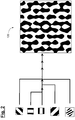
- the examination of only a partial area of the entire mirror surface takes place (with regard to the assumed large mirror surface), for which the CGH 120 corresponding to the in FIG Fig. 2 shown schematic diagram is equipped with a plurality of different CGH structures or functionalities.
- the CGH structures or useful functionalities it can typically, as in Fig. 2 indicated to act (locally varying) line grating of different orientation or grating period.
- the CGH 120 has both a first CGH structure or useful functionality suitable for testing a first mirror area (when the mirror is in position "A") and one for checking a second one Mirror area (corresponding to the position "B" of the mirror 101) suitable CGH structure or useful functionality.
- CGH structures or useful functionalities are realized in the CGH 120 by way of the known method of complex coding.
- the respective CGH structures or line grids can each be described by a phase function (with amplitude and phase), wherein the relevant terms can be added up with possibly different weightings.
- This results in a complex function which in turn can be binarized, with which, for example, those in the right part of Fig. 2 only schematically for a given point on the CGH shown resulting structure of the CGH 120 is obtained.
- the concerned, in the right part of Fig. 2 schematically shown resulting overall structure of the CGH 120 is characterized in particular by the fact that a plurality of test waves for one and the same specimen or mirror is provided due to the complex coding described above, these test waves are assigned to each other different faces of the mirror, ie in Paths of a shift of the mirror 101 relative to the CGH 120 allow an interferometric examination of a comparatively large, composed of the respective partial surfaces mirror surface using one and the same CGH 120.
- the line grids (referred to as "grids 1" or “grids 2") of the useful functionalities (ie of the CGH structures for testing the individual partial surfaces of the mirror 101) relative to the (as " Grid 3 "to” grid 5 ") designated calibration functions relatively heavily weighted, in addition, the weighting of the two Nutzfunktion procheen or" grid 1 "and” grid 2 "relative to each other (or in other embodiments only slightly, eg less than 20%, in particular less than 10% based on the respective stronger weighting differ from each other).
- the CGH 120 has a total of five different functionalities or CGH structures, with only two examples of these CGH structures for testing different mirror areas (when the mirror 101 is positioned in FIGS Fig. 1 mirror positions "A" and "B") can serve, and the other three CGH structures can serve as Kalibrierfunktion gleichen.
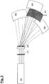
- Fig. 3 shows a schematic representation, wherein to Fig. 1 analogous or substantially functionally identical components are designated by "200" increased reference numerals.
- the test device according to Fig. 3 has a total of three calibration mirrors 302, 303 and 304, to each of which one of the above-described calibration functionalities of the CGH 320 is assigned.
- the mirror 301 becomes (as indicated by the double arrow in FIG Fig. 3 as already described) moves into different positions within the test apparatus for testing different mirror areas, wherein the useful functionality of the CGH 320 designed or assigned to the respective mirror area is used for the test.
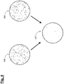
- the examination of a mirror using one and the same CGH can also be used to reduce or substantially increase the influence of undesired interference reflexes on the test result eliminate.
- Such perturbing reflections typically result from additional diffraction orders not desired in the test, in addition to the desired test wave impinging upon and reflected from the mirror surface by diffraction at the respective CGH structures, randomly or due to unavoidable errors within the CGH structure also after reflection at the mirror surface in the same way as the desired test waves run back and also contribute to the generated interferogram.
- the interferometric measurement can now be carried out with one and the same CGH for, for example, two mutually rotated or slightly displaced mirror positions in order to overcome or reduce this problem, wherein subsequently, as in FIG Fig. 4 an "OR operation" of the two obtained interferograms 450, 460 is performed, with the result that the distribution 470 resulting from this OR operation is at least largely freed from the influence of interfering reflections ("speckle pattern").
- the use of one and the same CGH in conjunction with two different mirror positions relative to the CGH can also be advantageously used in applications in which the CGH, due to size and configuration, already directly checks the entire mirror surface in a single step (FIG. ie without sub-steps for individual sub-areas of the mirror).
- Another advantageous aspect of the complex coding according to the invention of a CGH with a plurality of useful functionalities is that with such a CGH (such as in Fig. 2 shown) also the examination of free-form mirror surfaces (which have no intrinsic symmetry) is possible, which is also exploited here that can be encoded on one and the same position on the CGH different user functions or different line grids can be written.
- the provision according to the invention of at least two useful functionalities on one and the same position of the CGH can also - alternatively to the measurement of different partial surfaces of the mirror - also be used to measure different mirror geometries, in which case the individual functionalities or CGH structures do not differ in this case Sections of the same mirror, but different mirrors are assigned.
- the provision of at least two useful functionalities does not have to take place on the entire CGH surface, so that the useful functionalities can also be inscribed only on a subarea of the CGH in each case.
- the optionally existing calibration functionality must include the respective subareas of the useful functionalities.
- the invention is not limited to a certain number of useful functionalities or a certain number of calibration functionalities according to the embodiments described above, so that in particular, more than two useful functionalities or CGH structures, which may each be assigned to one of several partial surfaces of the mirror, are possible.
Landscapes
- Physics & Mathematics (AREA)
- General Physics & Mathematics (AREA)
- Chemical & Material Sciences (AREA)
- Analytical Chemistry (AREA)
- Signal Processing (AREA)
- Engineering & Computer Science (AREA)
- Geometry (AREA)
- Holo Graphy (AREA)
- Instruments For Measurement Of Length By Optical Means (AREA)
- Length Measuring Devices By Optical Means (AREA)
- Testing Of Optical Devices Or Fibers (AREA)
- Microscoopes, Condenser (AREA)
- Exposure And Positioning Against Photoresist Photosensitive Materials (AREA)
Description
Die Erfindung betrifft eine Prüfvorrichtung sowie ein Verfahren zum Prüfen eines Spiegels, insbesondere eines Spiegels einer mikrolithographischen Projektionsbelichtungsanlage.The invention relates to a test apparatus and a method for testing a mirror, in particular a mirror of a microlithographic projection exposure apparatus.
Mikrolithographie wird zur Herstellung mikrostrukturierter Bauelemente, wie beispielsweise integrierter Schaltkreise oder LCD's, angewendet. Der Mikrolithographieprozess wird in einer sogenannten Projektionsbelichtungsanlage durchgeführt, welche eine Beleuchtungseinrichtung und ein Projektionsobjektiv aufweist. Das Bild einer mittels der Beleuchtungseinrichtung beleuchteten Maske (= Retikel) wird hierbei mittels des Projektionsobjektivs auf ein mit einer lichtempfindlichen Schicht (Photoresist) beschichtetes und in der Bildebene des Projektionsobjektivs angeordnetes Substrat (z.B. ein Siliziumwafer) projiziert, um die Maskenstruktur auf die lichtempfindliche Beschichtung des Substrats zu übertragen.Microlithography is used to fabricate microstructured devices such as integrated circuits or LCDs. The microlithography process is carried out in a so-called projection exposure apparatus which has an illumination device and a projection objective. The image of a mask (= reticle) illuminated by means of the illumination device is hereby projected onto a substrate (eg a silicon wafer) coated with a photosensitive layer (photoresist) and arranged in the image plane of the projection objective in order to apply the mask structure to the photosensitive coating of the Transfer substrate.
In für den EUV-Bereich ausgelegten Projektionsobjektiven, d.h. bei Wellenlängen von z.B. etwa 13 nm oder etwa 7 nm, werden mangels Verfügbarkeit geeigneter lichtdurchlässiger refraktiver Materialien Spiegel als optische Komponenten für den Abbildungsprozess verwendet. Typische für EUV ausgelegte Projektionsobjektive, wie z.B. aus
Dabei ist u.a. auch der Betrieb von Spiegeln unter streifendem Einfall bekannt. Unter solchen unter streifendem Einfall betriebenen Spiegeln, deren Einsatz grundsätzlich im Hinblick auf die vergleichsweise hohen erreichbaren Reflektivitäten (von z.B. 80% und mehr) wünschenswert ist, werden z.B. Spiegel verstanden, für welche die bei der Reflexion der EUV-Strahlung auftretenden, auf die jeweilige Oberflächennormale bezogenen Reflexionswinkel wenigstens 65° betragen. Solche Spiegel werden auch als GI-Spiegel ("grazing incidence" = "streifender Einfall") bezeichnet.Among other things, the operation of mirrors under grazing incidence is known. Under such operated under grazing incidence mirrors whose use is generally desirable in terms of comparatively high achievable reflectivities (of eg 80% and more), for example, are understood mirror, for which occurring in the reflection of the EUV radiation to the respective Surface normal referenced reflection angle at least 65 °. Such mirrors are also referred to as GI-mirror ( "g razing ncidence i" = "grazing incidence").
Mit der Erhöhung der bildseitigen numerischen Apertur (NA) sowie auch mit der Realisierung von Anordnungen mit GI-Spiegeln geht typischerweise eine Vergrößerung der erforderlichen Spiegelflächen der in der Projektionsbelichtungsanlage eingesetzten Spiegel einher.The increase of the image-side numerical aperture (NA) as well as the realization of arrangements with GI mirrors is typically accompanied by an enlargement of the required mirror surfaces of the mirrors used in the projection exposure apparatus.
Zur hochgenauen Prüfung der Spiegel ist insbesondere der Einsatz Computergenerierter Hologramme (CGH) bekannt.For the high-precision examination of the mirrors, in particular the use of computer-generated holograms (CGH) is known.
Gemäß
Dabei tritt insbesondere bei GI-Spiegeln oder konkaven Spiegeln mit zunehmender Spiegelgröße in der Praxis das Problem auf, dass der Realisierung immer größerer CGH's Grenzen gesetzt sind, wobei typische CGH-Größen z.B. 6 Zoll (=15.24cm) oder 9 Zoll (=22.86cm) betragen können. Zwar kommt insoweit zur Reduzierung der benötigten CGH-Größen der Einsatz mehrerer CGH's für unterschiedliche, nacheinander eingestellte Spiegelpositionen in Betracht, jedoch ergeben sich in diesem Falle zusätzliche praktische Probleme, wobei insbesondere die Verlängerung der für die gesamte Prüfung benötigten zeitlichen Dauer sowie auch die Notwendigkeit einer exakten Zusammenführung der für die unterschiedlichen Spiegelbereiche erhaltenen Messergebnisse zu nennen sind.Particularly in the case of GI mirrors or concave mirrors with increasing mirror size, the problem arises in practice of limiting the realization of ever larger CGHs, typical CGH magnitudes being e.g. 6 inches (15.24cm) or 9 inches (= 22.86cm). Although the use of several CGHs for different, successively set mirror positions comes into consideration to reduce the required CGH sizes, in this case, additional practical problems arise, in particular the extension of the time required for the entire test as well as the need for a exact combination of the measurement results obtained for the different mirror ranges are to call.
Des Weiteren erweist es sich im Falle des Einsatzes mehrerer CGH's zur Prüfung ein- und desselben Spiegels als zunehmend schwierig, die in den CGH's typischerweise vorhandenen Fertigungsfehler von den im Rahmen der Prüfung zu ermittelnden Spiegelfehlern zuverlässig zu unterscheiden, wodurch im Ergebnis die Genauigkeit der Prüfung beeinträchtigt wird. Weitere Schwierigkeiten ergeben sich im Falle der Verwendung mehrerer CGH's aus den relativen Justagefreiheitsgraden (d.h. Abstände und relative Orientierung) von CGH und Spiegel zueinander.Furthermore, in the case of using several CGHs to test one and the same mirror, it has become increasingly difficult to reliably distinguish the manufacturing errors typically present in the CGHs from the mirror errors to be detected in the test, as a result of which the accuracy of the test is compromised becomes. Further difficulties arise in the case of using multiple CGHs from the relative adjustment degrees of freedom (ie, distances and relative orientation) of CGH and mirror to each other.
Des Weiteren ist es bekannt, eine Kalibrierung der bei der Spiegelprüfung eingesetzten CGH's unter Verwendung sogenannter komplex-kodierter CGH's zu realisieren, wobei in ein- und dasselbe CGH an der gleichen Position zusätzlich zu der für die eigentliche Prüfung benötigten "Nutzfunktionalität" (d.h. der entsprechend der Spiegelform ausgelegten CGH-Struktur zur Formung der mathematisch der Prüflingsform entsprechenden Wellenfront) wenigstens eine weitere "Kalibrierfunktionalität" zur Bereitstellung einer zur Kalibrierung bzw. Fehlerkorrektur dienenden Referenzwellenfront einkodiert wird.Furthermore, it is known to realize a calibration of the CGHs used in the mirror test using so-called complex-coded CGHs, wherein in one and the same CGH at the same position in addition to the "useful functionality" required for the actual test (ie the corresponding at least one further "calibration functionality" for providing a reference wavefront used for calibration or error correction is encoded in the mirror shape of the CGH structure designed to form the wavefront that mathematically corresponds to the test object shape.
Zum weiteren Stand der Technik wird lediglich beispielhaft auf
Vor dem obigen Hintergrund ist es eine Aufgabe der vorliegenden Erfindung, eine Prüfvorrichtung sowie ein Verfahren zum Prüfen eines Spiegels bereitzustellen, welche eine zuverlässige Prüfung auch von vergleichsweise großen Spiegelflächen unter zumindest teilweiser Vermeidung der vorstehend beschriebenen Probleme ermöglichen.Against the above background, it is an object of the present invention to provide a test apparatus and a method for inspecting a mirror, which allow a reliable examination of even relatively large mirror surfaces, at least partially avoiding the problems described above.
Diese Aufgabe wird durch die Merkmale der unabhängigen Patentansprüche gelöst.This object is solved by the features of the independent claims.
Bei einer erfindungsgemäßen Prüfvorrichtung zum Prüfen eines Spiegels, insbesondere eines Spiegels einer mikrolithographischen Projektionsbelichtungsanlage, wobei die Prüfvorrichtung ein Computer-generiertes Hologramm (CGH) aufweist und wobei eine Prüfung zumindest einer Teilfläche des Spiegels durch interferometrische Überlagerung einer von diesem Computer-generierten Hologramm auf den Spiegel gelenkten Prüfwelle und einer Referenzwelle durchführbar ist, ist das Computer-generierte Hologramm derart ausgelegt, dass es im Betrieb der Vorrichtung eine erste Prüfwelle zur Prüfung einer ersten Teilfläche des Spiegels durch interferometrische Überlagerung mit einer Referenzwelle in einer ersten Position des Spiegels und wenigstens eine zweite Prüfwelle zur Prüfung einer zweiten Teilfläche des Spiegels durch interferometrische Überlagerung mit einer Referenzwelle in einer zweiten Position des Spiegels bereitstellt, wobei das Computer-generierte Hologramm zur Bereitstellung der ersten und der zweiten Prüfwelle eine komplexe Kodierung mit voneinander verschiedenen CGH-Strukturen aufweistIn a test device according to the invention for testing a mirror, in particular a mirror of a microlithographic projection exposure apparatus, wherein the test apparatus comprises a computer-generated hologram (CGH) and wherein an examination of at least a partial surface of the mirror by interferometric superposition of a hologram generated by this computer on the mirror guided test wave and a reference wave is feasible, the computer-generated hologram is designed so that during operation of the device, a first test wave for testing a first partial surface of the mirror by interferometric superposition with a reference wave in a first position of the mirror and at least a second test wave for examining a second sub-area of the mirror by interferometric superposition with a reference wave in a second position of the mirror, the computer-generated hologram providing the first and the second test wave has a complex coding with mutually different CGH structures
Der Erfindung liegt insbesondere das Konzept zugrunde, innerhalb ein- und desselben zur Spiegelprüfung eingesetzten CGH's mehrere "Nutzfunktionalitäten" zu kombinieren, welche jeweils unterschiedlichen geometrischen Bereichen auf dem zu messenden Spiegel (d.h. unterschiedlichen Messpositionen des Spiegels bzw. Prüflings in der jeweiligen Prüfanordnung) zugeordnet sind. Dabei wird hier und im Weiteren unter dem Begriff "Nutzfunktionalität" jeweils eine CGH-Struktur verstanden, welche (z.B. in Form eines räumlich variierenden Liniengitters) die jeweilige Wellenfront formt, welche der "Prüflingsform" in einem bestimmten Bereich bzw. auf einer bestimmten Teilfläche des zu prüfenden Spiegels entspricht und somit zur interferometrischen Prüfung dieses Bereichs des Spiegels geeignet ist.In particular, the invention is based on the concept of combining several "useful functionalities" within one and the same CGH used for mirror testing, which are each assigned to different geometrical regions on the mirror to be measured (ie different measuring positions of the mirror or specimen in the respective test arrangement) , Here, and in the following, the term "useful functionality" is understood to mean in each case a CGH structure which (eg in the form of a spatially varying line grid) forms the respective wavefront which defines the "test object shape" in a specific region or on a specific sub-surface of the specimen corresponds to mirror to be tested and thus suitable for interferometric examination of this area of the mirror.
Dabei wird die erfindungsgemäße Kombination der vorstehend genannten Nutzfunktionalitäten in ein- und demselben CGH unter Anwendung des für sich bekannten Konzepts der komplexen Kodierung realisiert, wobei jedoch erfindungsgemäß im Unterschied zu den eingangs beschriebenen, herkömmlichen komplex-kodierten CGH's eine Mehrzahl unterschiedlicher Nutzfunktionalitäten zur Prüfung unterschiedlicher Spiegelbereiche (d.h. nicht lediglich zum Zwecke der Kalibrierung bei der Prüfung ein- und desselben Spiegelbereichs) eingesetzt werden.In this case, the inventive combination of the above-mentioned Nutzfunktionalitäten is realized in one and the same CGH using the known concept of complex coding, but according to the invention, in contrast to the above-described, conventional complex-coded CGH's a plurality of different functional functions for testing different mirror areas (ie not just for the purpose of calibration when testing one and the same mirror area).
Mit anderen Worten wird erfindungsgemäß je nach dem, in welcher Position sich der zu prüfende Spiegel relativ zum CGH befindet, die Prüfwelle für einen ersten Bereich der Spiegelfläche (beispielsweise "linke Hälfte des Spiegels") oder die Prüfwelle für einen zweiten Bereich der Spiegelfläche (beispielsweise "rechte Hälfte des Spiegels") genutzt, wobei diese beiden Prüfwellen gerade durch das in entsprechender Weise komplex-kodierte CGH bereitgestellt werden.In other words, according to the invention, depending on the position in which the mirror under test is relative to the CGH, the test wave for a first region of the mirror surface (for example, "left half of the mirror") or the test wave for a second region of the mirror surface (for example "right half of the mirror") are used, these two test waves are just provided by the correspondingly complex-coded CGH.
Auf Grund der erfindungsgemäßen Kombination mehrerer Nutzfunktionalitäten in ein- und demselben CGH, welche unterschiedlichen geometrischen Bereichen des zu prüfenden Spiegels zugeordnet sind, kann eine Prüfung auch bei großen konkaven Spiegeln oder großen GI-Spiegeln ohne Wechsel des CGH's dadurch realisiert werden, dass lediglich der betreffende Spiegel bzw. Prüfling bei unveränderter Position des CGH's bewegt wird mit der Folge, dass sich die für unterschiedliche Spiegelbereiche erhaltenen, den jeweiligen Nutzfunktionalitäten zugeordneten Messergebnisse auf dem überlappenden Bereich nur durch Justagefreiheitsgrade des Prüflings unterscheiden.Due to the combination according to the invention of a plurality of useful functionalities in one and the same CGH, which are assigned to different geometric regions of the mirror to be tested, a test can also be carried out at large concave mirrors or large GI mirrors without changing the CGH's be realized in that only the mirror in question or specimen is moved with unchanged position of the CGH's with the result that the received for different mirror areas, the respective utility functions associated measurement results on the overlapping area only by adjustment degrees of freedom of the specimen differ.
Die Erfindung hat insbesondere den Vorteil, dass auch bei Prüfung vergleichsweise großer Spiegelflächen nur ein einziges CGH benötigt wird und dieses zudem an derselben Position verbleibt, so dass u.a. eine ggf. wiederholte CGH-Justage für unterschiedliche Spiegelstellungen innerhalb der Prüfanordnung entfällt.The invention has the particular advantage that even when testing relatively large mirror surfaces only a single CGH is needed and this also remains at the same position, so that u.a. a possibly repeated CGH adjustment for different mirror positions within the test arrangement is eliminated.
Ein weiterer Vorteil besteht in einer erheblichen Reduzierung der für die Prüfung auch größerer Spiegelflächen erforderlichen Zeitdauer, was sich unmittelbar aus dem Wegfall herkömmlicher Prozeduren zum CGH-Wechsel sowie damit einhergehender Justageschritte etc. ergibt.Another advantage consists in a considerable reduction in the time required for testing even larger mirror surfaces, which results directly from the omission of conventional procedures for CGH change and associated adjustment steps, etc.
In Ausführungsformen der Erfindung ist die zweite Prüfwelle von der ersten Prüfwelle verschieden. Des Weiteren kann der Spiegel derart beschaffen sein, dass die zweite Teilfläche des Spiegels nicht durch eine Symmetrieoperation aus der ersten Teilfläche des Spiegels hervorgeht (wie dies etwa bei vorhandener Rotationssymmetrie des Spiegels der Falle wäre). Die Erfindung ermöglicht daher aufgrund der Bereitstellung unterschiedlicher Prüfwellen durch das Computer-generierte Hologramm (CGH), wobei voneinander verschiedenen Oberflächenbereichen bzw. Spiegelflächen jeweils eine dieser Prüfwellen zugeordnet ist, die Prüfung von Freiform-Spiegelflächen, welche keinerlei intrinsische Symmetrie aufweisen.In embodiments of the invention, the second test wave is different from the first test wave. Furthermore, the mirror may be such that the second sub-area of the mirror does not emerge from the first sub-area of the mirror by a symmetry operation (as would be the case with the rotational symmetry of the mirror of the trap, for example). Therefore, due to the provision of different test waves by the computer-generated hologram (CGH), wherein each of these different surface regions or mirror surfaces is assigned one of these test waves, the invention makes it possible to test free-form mirror surfaces which have no intrinsic symmetry whatsoever.
Gemäß der Erfindung weist das Computer-generierte Hologramm (CGH) zur Bereitstellung der ersten und der zweiten Prüfwelle eine komplexe Kodierung mit voneinander verschiedenen CGH-Strukturen auf.According to the invention, the computer-generated hologram (CGH) for providing the first and the second test wave has a complex coding with mutually different CGH structures.
Gemäß einer Ausführungsform ist das Computer-generierte Hologramm (CGH) ferner derart ausgelegt, dass die jeweiligen Intensitäten der ersten Prüfwelle und der zweiten Prüfwelle sich um nicht mehr als 20%, insbesondere um nicht mehr als 10%, voneinander unterscheiden.According to one embodiment, the computer-generated hologram (CGH) is further designed such that the respective intensities of the first test wave and the second test wave do not differ from one another by more than 20%, in particular by not more than 10%.
Gemäß einer Ausführungsform ist das Computer-generierte Hologramm (CGH) ferner derart ausgelegt, dass es im Betrieb der Vorrichtung wenigstens eine Kalibrierwelle zur interferometrischen Überlagerung mit einer Referenzwelle nach Reflexion dieser Kalibrierwelle an einem Kalibrierspiegel bereitstellt.According to one embodiment, the computer-generated hologram (CGH) is further designed such that it provides at least one calibration wave for interferometric superposition with a reference wave after reflection of this calibration wave at a calibration mirror during operation of the device.
Gemäß einer Ausführungsform ist das Computer-generierte Hologramm (CGH) ferner derart ausgelegt, dass es im Betrieb der Vorrichtung wenigstens zwei Kalibrierwellen, insbesondere wenigstens drei Kalibrierwellen, zur interferometrischen Überlagerung mit einer Referenzwelle nach Reflexion dieser Kalibrierwellen an voneinander verschiedenen Kalibrierspiegeln bereitstellt.According to one embodiment, the computer-generated hologram (CGH) is further designed such that during operation of the device it provides at least two calibration waves, in particular at least three calibration waves, for interferometric superposition with a reference wave after reflection of these calibration waves at mutually different calibration mirrors.
Die Erfindung betrifft weiter auch ein Verfahren zum Prüfen eines Spiegels, insbesondere eines Spiegels einer mikrolithographischen Projektionsbelichtungsanlage, wobei das Verfahren folgende Schritte aufweist:
- Aufnehmen eines ersten Interferogramms zwischen einer an dem Spiegel reflektierten ersten Prüfwelle und einer Referenzwelle;
- Aufnehmen eines zweiten Interferogramms zwischen einer an dem Spiegel reflektierten zweiten Prüfwelle und einer Referenzwelle;
- wobei die erste Prüfwelle und die zweite Prüfwelle von demselben Computer-generierten Hologramm (CGH) auf den Spiegel gelenkt werden, wobei das Computer-generierte Hologramm (CGH) zur Bereitstellung der ersten und der zweiten Prüfwelle eine komplexe Kodierung mit voneinander verschiedenen CGH-Strukturen aufweist; und
- wobei die Position des Spiegels zwischen dem Aufnehmen des ersten Interferogramms und dem Aufnehmen des zweiten Interferogramms verändert wird.
- Taking a first interferogram between a first test wave reflected on the mirror and a reference wave;
- Taking a second interferogram between a second test wave reflected on the mirror and a reference wave;
- wherein the first test wave and the second test wave are directed to the mirror by the same computer-generated hologram (CGH), the computer-generated hologram (CGH) having complex codings with mutually different CGH structures for providing the first and second test waves ; and
- wherein the position of the mirror is changed between the recording of the first interferogram and the recording of the second interferogram.
Gemäß einer Ausführungsform wird die erste Prüfwelle an einer ersten Teilfläche des Spiegels reflektiert, und die zweite Prüfwelle wird an einer von der ersten Teilfläche verschiedenen zweiten Teilfläche des Spiegels reflektiert.According to one embodiment, the first test wave is reflected at a first partial surface of the mirror, and the second test wave is reflected at a second partial surface of the mirror different from the first partial surface.
Gemäß einer Ausführungsform wird der Spiegel zwischen dem Aufnehmen des ersten Interferogramms und dem Aufnehmen des zweiten Interferogramms verschoben und/oder um eine vorgegebene Achse (je nach Anwendung z.B. um die Gravitationsachse) verdreht.According to one embodiment, the mirror is shifted between the recording of the first interferogram and the recording of the second interferogram and / or rotated about a predetermined axis (for example, about the axis of gravity, depending on the application).
Gemäß einer Ausführungsform verbleibt das Computer-generierte Hologramm (CGH) während der Aufnahme des ersten und zweiten Interferogramms in derselben Position.In one embodiment, the computer-generated hologram (CGH) remains in the same position during acquisition of the first and second interferograms.
Weitere Ausgestaltungen der Erfindung sind der Beschreibung sowie den Unteransprüchen zu entnehmen.Further embodiments of the invention are described in the description and the dependent claims.
Die Erfindung wird nachstehend anhand von in den beigefügten Abbildungen dargestellten Ausführungsbeispielen näher erläutert.The invention will be explained in more detail with reference to embodiments shown in the accompanying drawings.
Es zeigen:
- Figur 1-4
- schematische Darstellungen zur Erläuterung beispielhafter Ausführungsformen der vorliegenden Erfindung;
- Figur 5-6
- schematische Darstellungen zur Erläuterung eines herkömmlichen Funktionsprinzips einer interferometrischen Prüfvorrichtung zur Prüfung eines Spiegels; und
- Figur 7
- eine schematische Darstellung einer für den Betrieb im EUV ausgelegten Projektionsbelichtungsanlage.
- Figure 1-4
- schematic representations for explaining exemplary embodiments of the present invention;
- Figure 5-6
- schematic diagrams for explaining a conventional operating principle of an interferometric tester for testing a mirror; and
- FIG. 7
- a schematic representation of a designed for operation in the EUV projection exposure system.
Gemäß
Bei dem im Rahmen der Erfindung geprüften Spiegel kann es sich z.B. um einen beliebigen Spiegel der Projektionsbelichtungsanlage 10, beispielsweise die Spiegel 21 oder 22 des Projektionsobjektivs oder auch den Spiegel 7 der Beleuchtungseinrichtung, handeln.The mirror tested in the context of the invention may be e.g. to any mirror of the
Im Weiteren wird zunächst ein der Erfindung zugrundeliegendes Prinzip unter Bezugnahme auf die schematischen Abbildungen in
Erfindungsgemäß erfolgt eine Prüfung des Spiegels 101 unter Nutzung ein- und desselben CGH's 120 für die gesamte zu prüfende Spiegelfläche des Spiegels 101, wozu der Spiegel 101 (wie in
In diesen unterschiedlichen Spiegelpositionen "A" und "B" innerhalb der Prüfvorrichtung erfolgt (im Hinblick auf die angenommene große Spiegelfläche) jeweils die Prüfung nur eines Teilbereichs der gesamten Spiegelfläche, wobei für diese Prüfung das CGH 120 entsprechend der in
Mit anderen Worten weist das CGH 120 sowohl eine zur Prüfung eines ersten Spiegelbereichs (bei in Position "A" befindlichem Spiegel 101) geeignete erste CGH-Struktur bzw. Nutzfunktionalität als auch eine zur Prüfung eines zweiten Spiegelbereichs (entsprechend der Position "B" des Spiegels 101) geeignete CGH-Struktur bzw. Nutzfunktionalität auf.In other words, the
Diese CGH-Strukturen bzw. Nutzfunktionalitäten werden in dem CGH 120 im Wege des für sich bekannten Verfahrens der komplexen Kodierung realisiert. Hierbei können die jeweiligen CGH-Strukturen bzw. Liniengitter jeweils durch eine Phasenfunktion (mit Amplitude und Phase) beschrieben werden, wobei die betreffenden Terme mit gegebenenfalls unterschiedlichen Gewichtungen aufaddiert werden können. Auf diese Weise ergibt sich eine komplexe Funktion, welche wiederum binarisiert werden kann, womit z.B. die im rechten Teil von
Die betreffende, im rechten Teil von
In den nachfolgenden Tabellen 1a und 1b werden beispielhafte Ausführungsformen für die vorstehend beschriebene, mögliche Gewichtung der einzelnen CGH-Strukturen angegeben.In the following tables 1a and 1b, exemplary embodiments are given for the possible weighting of the individual CGH structures described above.
Wie aus Tabelle 1a und Tabelle 1b jeweils ersichtlich sind hierbei die (als "Gitter 1" bzw. "Gitter 2") bezeichneten Liniengitter der Nutzfunktionalitäten (d.h. der CGH-Strukturen zur Prüfung der einzelnen Teilflächen des Spiegels 101) relativ zu den (als "Gitter 3" bis "Gitter 5") bezeichneten Kalibrierfunktionalitäten relativ stark gewichtet, wobei zudem die Gewichtung der beiden Nutzfunktionalitäten bzw. "Gitter 1" und "Gitter 2" relativ zueinander übereinstimmt (oder in weiteren Ausführungsformen nur geringfügig, z.B. weniger als 20%, insbesondere weniger als 10% bezogen auf die jeweils stärkere Gewichtung voneinander abweichen). Zusätzlich zu den vorstehend genannten beiden Nutzfunktionalitäten bzw. CGH-Strukturen sind auf dem CGH 120 im Ausführungsbeispiel weitere (Nutz- oder auch Kalibrier-) Funktionalitäten kodiert (Gitter 3, Gitter 4 und Gitter 5 in Tabelle 1a und 1b).
Im Ausführungsbeispiel von
Gemäß einem weiteren Aspekt der Erfindung kann die Prüfung eines Spiegels unter Verwendung ein- und desselben CGH's (und unter Bewegen bzw. Verschieben der Spiegelposition relativ zu diesem CGH) auch dazu genutzt werden, den Einfluss unerwünschter Störreflexe auf das Prüfergebnis zu verringern bzw. weitgehend zu eliminieren. Solche Störreflexe resultieren typischerweise daraus, dass zusätzlich zu den erwünschten, durch Beugung an den jeweiligen CGH-Strukturen auf die Spiegelfläche treffenden und von dieser reflektierten Prüfwelle auch weitere, bei der Prüfung jedoch nicht erwünschte Beugungsordnungen zufällig bzw. aufgrund unvermeidbarer Fehler innerhalb der CGH-Struktur ebenfalls nach Reflexion an der Spiegelfläche auf demselben Weg wie die gewünschten Prüfwellen zurücklaufen und ebenfalls zu dem erzeugten Interferogramm beitragen können.According to a further aspect of the invention, the examination of a mirror using one and the same CGH (and moving the mirror position relative to this CGH) can also be used to reduce or substantially increase the influence of undesired interference reflexes on the test result eliminate. Such perturbing reflections typically result from additional diffraction orders not desired in the test, in addition to the desired test wave impinging upon and reflected from the mirror surface by diffraction at the respective CGH structures, randomly or due to unavoidable errors within the CGH structure also after reflection at the mirror surface in the same way as the desired test waves run back and also contribute to the generated interferogram.
Erfindungsgemäß kann nun zur Überwindung oder Reduzierung dieses Problems die interferometrische Messung mit ein- und demselben CGH für z.B. zwei zueinander verdrehte oder geringfügig verschobene Spiegelstellungen erfolgen, wobei anschließend, wie in
Im vorstehend beschriebenen Ausführungsbeispiel kann somit die Nutzung ein- und desselben CGH in Verbindung mit zwei unterschiedlichen Spiegelstellungen relativ zu dem CGH auch in Anwendungen vorteilhaft genutzt werden, bei denen das CGH bereits aufgrund Größe und Ausgestaltung eine unmittelbare Prüfung der gesamten Spiegelfläche in einem einzigen Schritt (d.h. ohne Teilschritte für einzelne Teilflächen des Spiegels) ermöglicht.Thus, in the embodiment described above, the use of one and the same CGH in conjunction with two different mirror positions relative to the CGH can also be advantageously used in applications in which the CGH, due to size and configuration, already directly checks the entire mirror surface in a single step (FIG. ie without sub-steps for individual sub-areas of the mirror).
Ein weiterer vorteilhafter Aspekt der erfindungsgemäßen komplexen Kodierung eines CGH mit mehreren Nutzfunktionalitäten ist, dass mit einem solchen CGH (wie z.B. in
Die erfindungsgemäße Bereitstellung von wenigstens zwei Nutzfunktionalitäten auf ein- und derselben Position des CGH kann ferner - alternativ zur Messung unterschiedlicher Teilflächen des Spiegels - auch zur Messung unterschiedlicher Spiegelgeometrien genutzt werden, in welchem Falle die einzelnen Nutzfunktionalitäten bzw. CGH-Strukturen in diesem Falle nicht unterschiedlichen Teilflächen desselben Spiegels, sondern unterschiedlichen Spiegeln zugeordnet sind.The provision according to the invention of at least two useful functionalities on one and the same position of the CGH can also - alternatively to the measurement of different partial surfaces of the mirror - also be used to measure different mirror geometries, in which case the individual functionalities or CGH structures do not differ in this case Sections of the same mirror, but different mirrors are assigned.
Des Weiteren muss die Bereitstellung von wenigstens zwei Nutzfunktionalitäten nicht auf der gesamten CGH-Fläche erfolgen, so dass die Nutzfunktionalitäten auch jeweils nur auf einem Teilbereich des CGH eingeschrieben sein können. In diesem Falle muss die gegebenenfalls vorhandene Kalibrierfunktionalität die jeweiligen Teilbereiche der Nutzfunktionalitäten umfassen.Furthermore, the provision of at least two useful functionalities does not have to take place on the entire CGH surface, so that the useful functionalities can also be inscribed only on a subarea of the CGH in each case. In this case, the optionally existing calibration functionality must include the respective subareas of the useful functionalities.
Des Weiteren ist die Erfindung nicht auf eine bestimmte Anzahl von Nutzfunktionalitäten oder eine bestimmte Anzahl von Kalibrierfunktionalitäten entsprechend den vorstehend beschriebenen Ausführungsformen beschränkt, so dass insbesondere auch mehr als zwei Nutzfunktionalitäten bzw. CGH-Strukturen, welche jeweils einer von mehreren Teilflächen des Spiegels zugeordnet sein können, möglich sind.Furthermore, the invention is not limited to a certain number of useful functionalities or a certain number of calibration functionalities according to the embodiments described above, so that in particular, more than two useful functionalities or CGH structures, which may each be assigned to one of several partial surfaces of the mirror, are possible.
Wenn die Erfindung auch anhand spezieller Ausführungsformen beschrieben wurde, erschließen sich für den Fachmann zahlreiche Variationen und alternative Ausführungsformen, z.B. durch Kombination und/oder Austausch von Merkmalen einzelner Ausführungsformen. Dementsprechend versteht es sich für den Fachmann, dass derartige Variationen und alternative Ausführungsformen von der vorliegenden Erfindung mit umfasst sind und die Reichweite der Erfindung nur im Sinne der beigefügten Patentansprüche beschränkt ist.While the invention has been described in terms of specific embodiments, numerous variations and alternative embodiments, e.g. by combination and / or exchange of features of individual embodiments. Accordingly, it will be understood by those skilled in the art that such variations and alternative embodiments are intended to be embraced by the present invention, and the scope of the invention is limited only by the terms of the appended claims.
Claims (8)
- Test appliance for testing a mirror, in particular a mirror of a microlithographic projection exposure apparatus, wherein the test appliance comprises a computer-generated hologram (CGH) and wherein a test can be carried out on at least a portion of the mirror by way of an interferometric superposition of a test wave that is directed onto the mirror by this computer-generated hologram and a reference wave,
wherein the computer-generated hologram (CGH) (120, 320) is designed in such a way that, during operation of the appliance, it provides a first test wave for testing a first portion of the mirror (101, 301) by interferometric superposition with a reference wave in a first position of the mirror (101, 301) and at least a second test wave for testing a second portion of the mirror (101, 301) by interferometric superposition with a reference wave in a second position of the mirror (101, 301);
characterized in that
the computer-generated hologram (CGH) (120, 320) for providing the first test wave and the second test wave has a complex encoding of CGH structures that differ from one another. - Test appliance according to Claim 1, characterized in that the computer-generated hologram (CGH) (120, 320) is further designed in such a way that the respective intensities of the first test wave and of the second test wave differ by no more than 20%, in particular by no more than 10%, from one another.
- Test appliance according to Claim 1 or 2, characterized in that the computer-generated hologram (CGH) (120, 320) is further designed in such a way that, during operation of the appliance, it provides at least one calibration wave for the interferometric superposition with a reference wave after the reflection of this calibration wave at a calibration mirror (302, 303, 304).
- Test appliance according to Claim 3, characterized in that the computer-generated hologram (CGH) (120, 320) is further designed in such a way that, during operation of the appliance, it provides at least two calibration waves, in particular at least three calibration waves, for the interferometric superposition with a reference wave after the reflection of these calibration waves at calibration mirrors (302, 303, 304) that differ from one another.
- Method for testing a mirror, in particular a mirror of a microlithographic projection exposure apparatus, wherein the method comprises the following steps:• recording a first interferogram between a first test wave that is reflected at the mirror (101, 301) and a reference wave;• recording a second interferogram between a second test wave that is reflected at the mirror (101, 301) and a reference wave;• wherein the first test wave and the second test wave are directed onto the mirror (101, 301) by the same computer-generated hologram (CGH) (120, 320), wherein the computer-generated hologram (CGH) (120, 130) for providing the first test wave and the second test wave has a complex encoding of CGH structures that differ from one another; and• wherein the position of the mirror (101, 301) is modified between the recording of the first interferogram and the recording of the second interferogram.
- Method according to Claim 5, characterized in that the first test wave is reflected at a first portion of the mirror and the second test wave is reflected at a second portion of the mirror that is different from the first portion.
- Method according to Claim 5 or 6, characterized in that the mirror is displaced and/or twisted between the recording of the first interferogram and the recording of the second interferogram.
- Method according to any one of Claims 5 to 7, characterized in that the computer-generated hologram (CGH) (120, 320) remains in the same position during the recording of the first interferogram and of the second interferogram.
Applications Claiming Priority (2)
| Application Number | Priority Date | Filing Date | Title |
|---|---|---|---|
| DE102015202695.7A DE102015202695A1 (en) | 2015-02-13 | 2015-02-13 | Test device and method for testing a mirror |
| PCT/EP2016/051957 WO2016128234A1 (en) | 2015-02-13 | 2016-01-29 | Test device and method for testing a mirror |
Publications (2)
| Publication Number | Publication Date |
|---|---|
| EP3256835A1 EP3256835A1 (en) | 2017-12-20 |
| EP3256835B1 true EP3256835B1 (en) | 2019-08-14 |
Family
ID=55315393
Family Applications (1)
| Application Number | Title | Priority Date | Filing Date |
|---|---|---|---|
| EP16703455.2A Active EP3256835B1 (en) | 2015-02-13 | 2016-01-29 | Test device and method for testing a mirror |
Country Status (5)
| Country | Link |
|---|---|
| US (1) | US10422718B2 (en) |
| EP (1) | EP3256835B1 (en) |
| JP (1) | JP6742322B2 (en) |
| DE (1) | DE102015202695A1 (en) |
| WO (1) | WO2016128234A1 (en) |
Families Citing this family (23)
| Publication number | Priority date | Publication date | Assignee | Title |
|---|---|---|---|---|
| JP6783801B2 (en) | 2015-05-20 | 2020-11-11 | カール・ツァイス・エスエムティー・ゲーエムベーハー | Measurement method and measurement arrangement of imaging optical system |
| DE102017204719A1 (en) * | 2017-03-21 | 2018-09-27 | Carl Zeiss Smt Gmbh | Metrology target |
| CN106949853B (en) * | 2017-04-12 | 2019-02-05 | 北京理工大学 | Simultaneous phase-shifting interferometer measuration system and method based on liquid crystal computed hologram |
| DE102017216401A1 (en) | 2017-09-15 | 2018-10-11 | Carl Zeiss Smt Gmbh | Computer-generated hologram (CGH), as well as method for its production |
| DE102017217371A1 (en) * | 2017-09-29 | 2019-04-04 | Carl Zeiss Smt Gmbh | Method and device for characterizing the surface shape of an optical element |
| WO2019081187A1 (en) | 2017-10-25 | 2019-05-02 | Carl Zeiss Smt Gmbh | Method for temperature control of a component |
| DE102018209175B4 (en) * | 2018-06-08 | 2024-01-04 | Carl Zeiss Smt Gmbh | Computer-generated hologram (CGH), interferometric test arrangement, and method for characterizing the surface shape of an optical element |
| CN108895972A (en) * | 2018-06-27 | 2018-11-27 | 中国科学院光电技术研究所 | A kind of method and apparatus based on the optical element vertex radius measurement for calculating holography |
| DE102018211853A1 (en) | 2018-07-17 | 2020-01-23 | Carl Zeiss Smt Gmbh | Method and device for characterizing the surface shape of an optical element |
| DE102019201762A1 (en) * | 2019-02-12 | 2020-08-13 | Carl Zeiss Smt Gmbh | Device and method for characterizing the surface shape of a test object |
| DE102019204096A1 (en) * | 2019-03-26 | 2020-10-01 | Carl Zeiss Smt Gmbh | Measurement method for the interferometric determination of a surface shape |
| DE102019215707A1 (en) * | 2019-10-14 | 2021-04-15 | Carl Zeiss Smt Gmbh | Method and device for characterizing the surface shape of an optical element |
| DE102020205891A1 (en) | 2020-05-11 | 2021-11-11 | Carl Zeiss Smt Gmbh | Method and measuring device for interferometric measurement of a shape of a surface |
| DE102020209580B3 (en) | 2020-07-30 | 2021-09-23 | Carl Zeiss Smt Gmbh | Method for determining a wavefront generated by means of a diffractive optical element, method for producing a diffractive optical element and measuring device for interferometric shape measurement of a surface of a test object |
| CN113008159B (en) * | 2021-02-05 | 2022-10-11 | 中国人民解放军国防科技大学 | Variable one-dimensional spherical aberration interferometry system of non-cylindrical surface shape and application method |
| RU2766855C1 (en) * | 2021-02-25 | 2022-03-16 | Акционерное общество "Научно-производственное объединение "Государственный институт прикладной оптики" (АО "НПО ГИПО") | Axial synthesized holographic optical element |
| RU205115U1 (en) * | 2021-02-25 | 2021-06-28 | Акционерное общество "Научно-производственное объединение "Государственный институт прикладной оптики" (АО "НПО ГИПО") | AXIAL SYNTHESIZED HOLOGRAM OPTICAL ELEMENT |
| CN112923871B (en) * | 2021-03-31 | 2021-12-28 | 中国科学院长春光学精密机械与物理研究所 | Free-form surface reflector curvature radius detection device and method |
| DE102021213383A1 (en) | 2021-11-29 | 2023-06-01 | Carl Zeiss Smt Gmbh | Computer-generated hologram (CGH) and method for designing a CGH |
| CN114252023B (en) * | 2021-12-28 | 2022-10-21 | 中国科学院光电技术研究所 | Computer-aided adjusting device and method for aspheric surface calculation holographic detection |
| DE102022206650A1 (en) | 2022-06-30 | 2024-01-04 | Carl Zeiss Smt Gmbh | Method and measuring arrangement for the interferometric determination of the surface shape of a test specimen |
| DE102022209513A1 (en) | 2022-09-12 | 2023-10-19 | Carl Zeiss Smt Gmbh | Method for calibrating a spherical wave, and testing system for the interferometric determination of the surface shape of a test specimen |
| DE102022214271B4 (en) | 2022-12-22 | 2024-02-29 | Carl Zeiss Smt Gmbh | Device for the interferometric determination of a fit error of an optical surface |
Citations (1)
| Publication number | Priority date | Publication date | Assignee | Title |
|---|---|---|---|---|
| US20120170038A1 (en) * | 2009-09-17 | 2012-07-05 | Sagem Defense Securite | Alignment Method for Inspecting a Mirror |
Family Cites Families (11)
| Publication number | Priority date | Publication date | Assignee | Title |
|---|---|---|---|---|
| EP1649241A1 (en) * | 2002-11-21 | 2006-04-26 | Carl Zeiss SMT AG | Method for calibrating an interferometer, method for qualifying an object, and method for producing an object |
| EP1737454A4 (en) * | 2004-04-22 | 2007-08-08 | Mor Research Applic Ltd | Method of food intake management |
| WO2005114101A1 (en) * | 2004-05-14 | 2005-12-01 | Carl Zeiss Smt Ag | Method of manufacturing an optical element |
| WO2006125609A1 (en) * | 2005-05-24 | 2006-11-30 | Carl Zeiss Smt Ag | Method of aligning an optical system |
| DE102007028371B4 (en) * | 2007-06-13 | 2012-05-16 | Seereal Technologies S.A. | Device for light modulation |
| WO2009006919A1 (en) | 2007-07-09 | 2009-01-15 | Carl Zeiss Smt Ag | Method of measuring a deviation an optical surface from a target shape |
| JP4986754B2 (en) | 2007-07-27 | 2012-07-25 | キヤノン株式会社 | Illumination optical system and exposure apparatus having the same |
| DE102008048844A1 (en) * | 2007-09-25 | 2009-05-14 | Carl Zeiss Smt Ag | Method and system for measuring a surface of an object |
| DE102012217800A1 (en) | 2012-09-28 | 2014-04-03 | Carl Zeiss Smt Gmbh | Diffractive optical element and measuring method |
| DE102015202676B4 (en) | 2015-02-13 | 2016-09-22 | Carl Zeiss Smt Gmbh | Interferometric measuring device |
| DE102015209490A1 (en) | 2015-05-22 | 2016-11-24 | Carl Zeiss Smt Gmbh | Interferometric measuring arrangement |
-
2015
- 2015-02-13 DE DE102015202695.7A patent/DE102015202695A1/en not_active Ceased
-
2016
- 2016-01-29 JP JP2017539281A patent/JP6742322B2/en active Active
- 2016-01-29 WO PCT/EP2016/051957 patent/WO2016128234A1/en active Application Filing
- 2016-01-29 EP EP16703455.2A patent/EP3256835B1/en active Active
-
2017
- 2017-08-14 US US15/676,729 patent/US10422718B2/en active Active
Patent Citations (1)
| Publication number | Priority date | Publication date | Assignee | Title |
|---|---|---|---|---|
| US20120170038A1 (en) * | 2009-09-17 | 2012-07-05 | Sagem Defense Securite | Alignment Method for Inspecting a Mirror |
Also Published As
| Publication number | Publication date |
|---|---|
| US10422718B2 (en) | 2019-09-24 |
| DE102015202695A1 (en) | 2016-08-18 |
| JP2018511783A (en) | 2018-04-26 |
| WO2016128234A1 (en) | 2016-08-18 |
| US20170343449A1 (en) | 2017-11-30 |
| EP3256835A1 (en) | 2017-12-20 |
| JP6742322B2 (en) | 2020-08-19 |
Similar Documents
| Publication | Publication Date | Title |
|---|---|---|
| EP3256835B1 (en) | Test device and method for testing a mirror | |
| EP3298446A2 (en) | Measuring method and measuring arrangement for an imaging optical system | |
| DE102012204704A1 (en) | Measuring device for measuring an imaging quality of an EUV objective | |
| DE102018209175B4 (en) | Computer-generated hologram (CGH), interferometric test arrangement, and method for characterizing the surface shape of an optical element | |
| DE102016212477A1 (en) | Measuring method and measuring system for the interferometric measurement of the imaging quality of an optical imaging system | |
| DE102010038748A1 (en) | Method for producing a mirror with at least two mirror surfaces, mirrors of a microlithography projection exposure apparatus and projection exposure apparatus | |
| DE102017217371A1 (en) | Method and device for characterizing the surface shape of an optical element | |
| DE102009019140A1 (en) | Method and calibration mask for calibrating a position measuring device | |
| DE102005041373A1 (en) | Method of wavefront measurement calibration of projection optical system used in lithographic scanner equipment, forms interference pattern from object pattern and image measurement patterns | |
| WO2019101419A1 (en) | Method and device for calibrating a diffractive measuring structure | |
| DE102014206589A1 (en) | Method for adjusting a mirror of a microlithographic projection exposure apparatus | |
| DE102012100311B4 (en) | A method and apparatus for calibrating the wavefront error of a computer generated hologram for optical surface inspection | |
| DE102015220588A1 (en) | Measuring method and measuring arrangement for an imaging optical system | |
| EP4336139A1 (en) | Method for calibrating a spherical wave and test system for interferometrically determining the surface shape of a test object | |
| WO2021063766A1 (en) | Measuring apparatus for interferometrically determining a surface shape | |
| WO2024002799A1 (en) | Method and measuring assembly for an interferometric determination of the surface shape of a test object | |
| DE102017216401A1 (en) | Computer-generated hologram (CGH), as well as method for its production | |
| DE102007021953B4 (en) | Interferometric measuring device for measuring a surface of a test object | |
| DE102015209489A1 (en) | Interferometric measuring device | |
| DE102021202909A1 (en) | Measuring device for interferometric measuring of a surface shape | |
| DE102022207884B4 (en) | Measuring device, method for interferometric measurement, processing method, optical element and lithography system | |
| DE102021211172B3 (en) | Method and device for characterizing the surface shape of an optical element | |
| DE102021203123A1 (en) | Computer-generated hologram (CGH) and interferometric measurement setup to determine the surface shape of a test object | |
| DE10392704B4 (en) | Method for evaluating the homogeneity of the refractive index of optical components | |
| WO2022037898A1 (en) | Method and device for characterising the surface shape of an optical element |
Legal Events
| Date | Code | Title | Description |
|---|---|---|---|
| STAA | Information on the status of an ep patent application or granted ep patent |
Free format text: STATUS: THE INTERNATIONAL PUBLICATION HAS BEEN MADE |
|
| PUAI | Public reference made under article 153(3) epc to a published international application that has entered the european phase |
Free format text: ORIGINAL CODE: 0009012 |
|
| STAA | Information on the status of an ep patent application or granted ep patent |
Free format text: STATUS: REQUEST FOR EXAMINATION WAS MADE |
|
| 17P | Request for examination filed |
Effective date: 20170711 |
|
| AK | Designated contracting states |
Kind code of ref document: A1 Designated state(s): AL AT BE BG CH CY CZ DE DK EE ES FI FR GB GR HR HU IE IS IT LI LT LU LV MC MK MT NL NO PL PT RO RS SE SI SK SM TR |
|
| AX | Request for extension of the european patent |
Extension state: BA ME |
|
| DAV | Request for validation of the european patent (deleted) | ||
| DAX | Request for extension of the european patent (deleted) | ||
| STAA | Information on the status of an ep patent application or granted ep patent |
Free format text: STATUS: EXAMINATION IS IN PROGRESS |
|
| 17Q | First examination report despatched |
Effective date: 20180720 |
|
| REG | Reference to a national code |
Ref country code: DE Ref legal event code: R079 Ref document number: 502016006076 Country of ref document: DE Free format text: PREVIOUS MAIN CLASS: G01M0011020000 Ipc: G03F0007200000 |
|
| RIC1 | Information provided on ipc code assigned before grant |
Ipc: G01M 11/02 20060101ALI20190307BHEP Ipc: G01M 11/00 20060101ALI20190307BHEP Ipc: G01B 9/021 20060101ALI20190307BHEP Ipc: G01B 9/02 20060101ALI20190307BHEP Ipc: G03F 7/20 20060101AFI20190307BHEP |
|
| GRAP | Despatch of communication of intention to grant a patent |
Free format text: ORIGINAL CODE: EPIDOSNIGR1 |
|
| STAA | Information on the status of an ep patent application or granted ep patent |
Free format text: STATUS: GRANT OF PATENT IS INTENDED |
|
| INTG | Intention to grant announced |
Effective date: 20190423 |
|
| GRAS | Grant fee paid |
Free format text: ORIGINAL CODE: EPIDOSNIGR3 |
|
| GRAA | (expected) grant |
Free format text: ORIGINAL CODE: 0009210 |
|
| STAA | Information on the status of an ep patent application or granted ep patent |
Free format text: STATUS: THE PATENT HAS BEEN GRANTED |
|
| AK | Designated contracting states |
Kind code of ref document: B1 Designated state(s): AL AT BE BG CH CY CZ DE DK EE ES FI FR GB GR HR HU IE IS IT LI LT LU LV MC MK MT NL NO PL PT RO RS SE SI SK SM TR |
|
| REG | Reference to a national code |
Ref country code: GB Ref legal event code: FG4D Free format text: NOT ENGLISH |
|
| REG | Reference to a national code |
Ref country code: CH Ref legal event code: EP Ref country code: AT Ref legal event code: REF Ref document number: 1167736 Country of ref document: AT Kind code of ref document: T Effective date: 20190815 |
|
| REG | Reference to a national code |
Ref country code: IE Ref legal event code: FG4D Free format text: LANGUAGE OF EP DOCUMENT: GERMAN |
|
| REG | Reference to a national code |
Ref country code: DE Ref legal event code: R096 Ref document number: 502016006076 Country of ref document: DE |
|
| REG | Reference to a national code |
Ref country code: NL Ref legal event code: FP |
|
| REG | Reference to a national code |
Ref country code: LT Ref legal event code: MG4D |
|
| PG25 | Lapsed in a contracting state [announced via postgrant information from national office to epo] |
Ref country code: SE Free format text: LAPSE BECAUSE OF FAILURE TO SUBMIT A TRANSLATION OF THE DESCRIPTION OR TO PAY THE FEE WITHIN THE PRESCRIBED TIME-LIMIT Effective date: 20190814 Ref country code: BG Free format text: LAPSE BECAUSE OF FAILURE TO SUBMIT A TRANSLATION OF THE DESCRIPTION OR TO PAY THE FEE WITHIN THE PRESCRIBED TIME-LIMIT Effective date: 20191114 Ref country code: HR Free format text: LAPSE BECAUSE OF FAILURE TO SUBMIT A TRANSLATION OF THE DESCRIPTION OR TO PAY THE FEE WITHIN THE PRESCRIBED TIME-LIMIT Effective date: 20190814 Ref country code: PT Free format text: LAPSE BECAUSE OF FAILURE TO SUBMIT A TRANSLATION OF THE DESCRIPTION OR TO PAY THE FEE WITHIN THE PRESCRIBED TIME-LIMIT Effective date: 20191216 Ref country code: NO Free format text: LAPSE BECAUSE OF FAILURE TO SUBMIT A TRANSLATION OF THE DESCRIPTION OR TO PAY THE FEE WITHIN THE PRESCRIBED TIME-LIMIT Effective date: 20191114 Ref country code: LT Free format text: LAPSE BECAUSE OF FAILURE TO SUBMIT A TRANSLATION OF THE DESCRIPTION OR TO PAY THE FEE WITHIN THE PRESCRIBED TIME-LIMIT Effective date: 20190814 Ref country code: FI Free format text: LAPSE BECAUSE OF FAILURE TO SUBMIT A TRANSLATION OF THE DESCRIPTION OR TO PAY THE FEE WITHIN THE PRESCRIBED TIME-LIMIT Effective date: 20190814 |
|
| PG25 | Lapsed in a contracting state [announced via postgrant information from national office to epo] |
Ref country code: GR Free format text: LAPSE BECAUSE OF FAILURE TO SUBMIT A TRANSLATION OF THE DESCRIPTION OR TO PAY THE FEE WITHIN THE PRESCRIBED TIME-LIMIT Effective date: 20191115 Ref country code: LV Free format text: LAPSE BECAUSE OF FAILURE TO SUBMIT A TRANSLATION OF THE DESCRIPTION OR TO PAY THE FEE WITHIN THE PRESCRIBED TIME-LIMIT Effective date: 20190814 Ref country code: RS Free format text: LAPSE BECAUSE OF FAILURE TO SUBMIT A TRANSLATION OF THE DESCRIPTION OR TO PAY THE FEE WITHIN THE PRESCRIBED TIME-LIMIT Effective date: 20190814 Ref country code: ES Free format text: LAPSE BECAUSE OF FAILURE TO SUBMIT A TRANSLATION OF THE DESCRIPTION OR TO PAY THE FEE WITHIN THE PRESCRIBED TIME-LIMIT Effective date: 20190814 Ref country code: IS Free format text: LAPSE BECAUSE OF FAILURE TO SUBMIT A TRANSLATION OF THE DESCRIPTION OR TO PAY THE FEE WITHIN THE PRESCRIBED TIME-LIMIT Effective date: 20191214 Ref country code: AL Free format text: LAPSE BECAUSE OF FAILURE TO SUBMIT A TRANSLATION OF THE DESCRIPTION OR TO PAY THE FEE WITHIN THE PRESCRIBED TIME-LIMIT Effective date: 20190814 |
|
| PG25 | Lapsed in a contracting state [announced via postgrant information from national office to epo] |
Ref country code: TR Free format text: LAPSE BECAUSE OF FAILURE TO SUBMIT A TRANSLATION OF THE DESCRIPTION OR TO PAY THE FEE WITHIN THE PRESCRIBED TIME-LIMIT Effective date: 20190814 |
|
| PG25 | Lapsed in a contracting state [announced via postgrant information from national office to epo] |
Ref country code: EE Free format text: LAPSE BECAUSE OF FAILURE TO SUBMIT A TRANSLATION OF THE DESCRIPTION OR TO PAY THE FEE WITHIN THE PRESCRIBED TIME-LIMIT Effective date: 20190814 Ref country code: IT Free format text: LAPSE BECAUSE OF FAILURE TO SUBMIT A TRANSLATION OF THE DESCRIPTION OR TO PAY THE FEE WITHIN THE PRESCRIBED TIME-LIMIT Effective date: 20190814 Ref country code: DK Free format text: LAPSE BECAUSE OF FAILURE TO SUBMIT A TRANSLATION OF THE DESCRIPTION OR TO PAY THE FEE WITHIN THE PRESCRIBED TIME-LIMIT Effective date: 20190814 Ref country code: RO Free format text: LAPSE BECAUSE OF FAILURE TO SUBMIT A TRANSLATION OF THE DESCRIPTION OR TO PAY THE FEE WITHIN THE PRESCRIBED TIME-LIMIT Effective date: 20190814 Ref country code: PL Free format text: LAPSE BECAUSE OF FAILURE TO SUBMIT A TRANSLATION OF THE DESCRIPTION OR TO PAY THE FEE WITHIN THE PRESCRIBED TIME-LIMIT Effective date: 20190814 |
|
| PG25 | Lapsed in a contracting state [announced via postgrant information from national office to epo] |
Ref country code: IS Free format text: LAPSE BECAUSE OF FAILURE TO SUBMIT A TRANSLATION OF THE DESCRIPTION OR TO PAY THE FEE WITHIN THE PRESCRIBED TIME-LIMIT Effective date: 20200224 Ref country code: SK Free format text: LAPSE BECAUSE OF FAILURE TO SUBMIT A TRANSLATION OF THE DESCRIPTION OR TO PAY THE FEE WITHIN THE PRESCRIBED TIME-LIMIT Effective date: 20190814 Ref country code: CZ Free format text: LAPSE BECAUSE OF FAILURE TO SUBMIT A TRANSLATION OF THE DESCRIPTION OR TO PAY THE FEE WITHIN THE PRESCRIBED TIME-LIMIT Effective date: 20190814 Ref country code: SM Free format text: LAPSE BECAUSE OF FAILURE TO SUBMIT A TRANSLATION OF THE DESCRIPTION OR TO PAY THE FEE WITHIN THE PRESCRIBED TIME-LIMIT Effective date: 20190814 |
|
| REG | Reference to a national code |
Ref country code: DE Ref legal event code: R097 Ref document number: 502016006076 Country of ref document: DE |
|
| PLBE | No opposition filed within time limit |
Free format text: ORIGINAL CODE: 0009261 |
|
| STAA | Information on the status of an ep patent application or granted ep patent |
Free format text: STATUS: NO OPPOSITION FILED WITHIN TIME LIMIT |
|
| PG2D | Information on lapse in contracting state deleted |
Ref country code: IS |
|
| 26N | No opposition filed |
Effective date: 20200603 |
|
| PG25 | Lapsed in a contracting state [announced via postgrant information from national office to epo] |
Ref country code: SI Free format text: LAPSE BECAUSE OF FAILURE TO SUBMIT A TRANSLATION OF THE DESCRIPTION OR TO PAY THE FEE WITHIN THE PRESCRIBED TIME-LIMIT Effective date: 20190814 Ref country code: MC Free format text: LAPSE BECAUSE OF FAILURE TO SUBMIT A TRANSLATION OF THE DESCRIPTION OR TO PAY THE FEE WITHIN THE PRESCRIBED TIME-LIMIT Effective date: 20190814 |
|
| REG | Reference to a national code |
Ref country code: CH Ref legal event code: PL |
|
| GBPC | Gb: european patent ceased through non-payment of renewal fee |
Effective date: 20200129 |
|
| REG | Reference to a national code |
Ref country code: BE Ref legal event code: MM Effective date: 20200131 |
|
| PG25 | Lapsed in a contracting state [announced via postgrant information from national office to epo] |
Ref country code: FR Free format text: LAPSE BECAUSE OF NON-PAYMENT OF DUE FEES Effective date: 20200131 Ref country code: LU Free format text: LAPSE BECAUSE OF NON-PAYMENT OF DUE FEES Effective date: 20200129 Ref country code: GB Free format text: LAPSE BECAUSE OF NON-PAYMENT OF DUE FEES Effective date: 20200129 |
|
| PG25 | Lapsed in a contracting state [announced via postgrant information from national office to epo] |
Ref country code: CH Free format text: LAPSE BECAUSE OF NON-PAYMENT OF DUE FEES Effective date: 20200131 Ref country code: BE Free format text: LAPSE BECAUSE OF NON-PAYMENT OF DUE FEES Effective date: 20200131 Ref country code: LI Free format text: LAPSE BECAUSE OF NON-PAYMENT OF DUE FEES Effective date: 20200131 |
|
| PG25 | Lapsed in a contracting state [announced via postgrant information from national office to epo] |
Ref country code: IE Free format text: LAPSE BECAUSE OF NON-PAYMENT OF DUE FEES Effective date: 20200129 |
|
| REG | Reference to a national code |
Ref country code: AT Ref legal event code: MM01 Ref document number: 1167736 Country of ref document: AT Kind code of ref document: T Effective date: 20210129 |
|
| PG25 | Lapsed in a contracting state [announced via postgrant information from national office to epo] |
Ref country code: AT Free format text: LAPSE BECAUSE OF NON-PAYMENT OF DUE FEES Effective date: 20210129 |
|
| PG25 | Lapsed in a contracting state [announced via postgrant information from national office to epo] |
Ref country code: MT Free format text: LAPSE BECAUSE OF FAILURE TO SUBMIT A TRANSLATION OF THE DESCRIPTION OR TO PAY THE FEE WITHIN THE PRESCRIBED TIME-LIMIT Effective date: 20190814 Ref country code: CY Free format text: LAPSE BECAUSE OF FAILURE TO SUBMIT A TRANSLATION OF THE DESCRIPTION OR TO PAY THE FEE WITHIN THE PRESCRIBED TIME-LIMIT Effective date: 20190814 |
|
| PG25 | Lapsed in a contracting state [announced via postgrant information from national office to epo] |
Ref country code: MK Free format text: LAPSE BECAUSE OF FAILURE TO SUBMIT A TRANSLATION OF THE DESCRIPTION OR TO PAY THE FEE WITHIN THE PRESCRIBED TIME-LIMIT Effective date: 20190814 |
|
| P01 | Opt-out of the competence of the unified patent court (upc) registered |
Effective date: 20230525 |
|
| PGFP | Annual fee paid to national office [announced via postgrant information from national office to epo] |
Ref country code: NL Payment date: 20240119 Year of fee payment: 9 |
|
| PGFP | Annual fee paid to national office [announced via postgrant information from national office to epo] |
Ref country code: DE Payment date: 20240119 Year of fee payment: 9 |