EP3255254A1 - Outer airseal abradable rub strip - Google Patents
Outer airseal abradable rub strip Download PDFInfo
- Publication number
- EP3255254A1 EP3255254A1 EP17162495.0A EP17162495A EP3255254A1 EP 3255254 A1 EP3255254 A1 EP 3255254A1 EP 17162495 A EP17162495 A EP 17162495A EP 3255254 A1 EP3255254 A1 EP 3255254A1
- Authority
- EP
- European Patent Office
- Prior art keywords
- blade outer
- metallic matrix
- outer airseal
- airseal
- weight
- Prior art date
- Legal status (The legal status is an assumption and is not a legal conclusion. Google has not performed a legal analysis and makes no representation as to the accuracy of the status listed.)
- Granted
Links
- 239000011159 matrix material Substances 0.000 claims abstract description 63
- PXHVJJICTQNCMI-UHFFFAOYSA-N Nickel Chemical compound [Ni] PXHVJJICTQNCMI-UHFFFAOYSA-N 0.000 claims abstract description 56
- 239000000758 substrate Substances 0.000 claims abstract description 55
- 238000000576 coating method Methods 0.000 claims abstract description 49
- 239000011248 coating agent Substances 0.000 claims abstract description 47
- 239000000314 lubricant Substances 0.000 claims abstract description 32
- 239000007787 solid Substances 0.000 claims abstract description 32
- XEEYBQQBJWHFJM-UHFFFAOYSA-N Iron Chemical compound [Fe] XEEYBQQBJWHFJM-UHFFFAOYSA-N 0.000 claims abstract description 28
- 229910052759 nickel Inorganic materials 0.000 claims abstract description 22
- 239000011651 chromium Substances 0.000 claims abstract description 20
- 239000010941 cobalt Substances 0.000 claims abstract description 15
- 229910017052 cobalt Inorganic materials 0.000 claims abstract description 15
- GUTLYIVDDKVIGB-UHFFFAOYSA-N cobalt atom Chemical compound [Co] GUTLYIVDDKVIGB-UHFFFAOYSA-N 0.000 claims abstract description 15
- 229910052742 iron Inorganic materials 0.000 claims abstract description 14
- 229910052782 aluminium Inorganic materials 0.000 claims abstract description 12
- 229910052804 chromium Inorganic materials 0.000 claims abstract description 11
- 239000010949 copper Substances 0.000 claims abstract description 11
- VYZAMTAEIAYCRO-UHFFFAOYSA-N Chromium Chemical compound [Cr] VYZAMTAEIAYCRO-UHFFFAOYSA-N 0.000 claims abstract description 9
- RYGMFSIKBFXOCR-UHFFFAOYSA-N Copper Chemical compound [Cu] RYGMFSIKBFXOCR-UHFFFAOYSA-N 0.000 claims abstract description 9
- XAGFODPZIPBFFR-UHFFFAOYSA-N aluminium Chemical compound [Al] XAGFODPZIPBFFR-UHFFFAOYSA-N 0.000 claims abstract description 9
- 229910052802 copper Inorganic materials 0.000 claims abstract description 9
- 238000000034 method Methods 0.000 claims description 32
- 239000007921 spray Substances 0.000 claims description 27
- 239000013078 crystal Substances 0.000 claims description 18
- 229910052735 hafnium Inorganic materials 0.000 claims description 10
- 229910052710 silicon Inorganic materials 0.000 claims description 10
- 229910052727 yttrium Inorganic materials 0.000 claims description 8
- 239000010955 niobium Substances 0.000 claims description 7
- 229910000601 superalloy Inorganic materials 0.000 claims description 7
- 230000004888 barrier function Effects 0.000 claims description 6
- 238000004519 manufacturing process Methods 0.000 claims description 6
- ZOKXTWBITQBERF-UHFFFAOYSA-N Molybdenum Chemical compound [Mo] ZOKXTWBITQBERF-UHFFFAOYSA-N 0.000 claims description 5
- VBJZVLUMGGDVMO-UHFFFAOYSA-N hafnium atom Chemical compound [Hf] VBJZVLUMGGDVMO-UHFFFAOYSA-N 0.000 claims description 5
- 229910052750 molybdenum Inorganic materials 0.000 claims description 5
- 239000011733 molybdenum Substances 0.000 claims description 5
- 229910052758 niobium Inorganic materials 0.000 claims description 5
- GUCVJGMIXFAOAE-UHFFFAOYSA-N niobium atom Chemical compound [Nb] GUCVJGMIXFAOAE-UHFFFAOYSA-N 0.000 claims description 5
- 229910052702 rhenium Inorganic materials 0.000 claims description 5
- WUAPFZMCVAUBPE-UHFFFAOYSA-N rhenium atom Chemical compound [Re] WUAPFZMCVAUBPE-UHFFFAOYSA-N 0.000 claims description 5
- 239000010703 silicon Substances 0.000 claims description 5
- 229910052715 tantalum Inorganic materials 0.000 claims description 5
- GUVRBAGPIYLISA-UHFFFAOYSA-N tantalum atom Chemical compound [Ta] GUVRBAGPIYLISA-UHFFFAOYSA-N 0.000 claims description 5
- WFKWXMTUELFFGS-UHFFFAOYSA-N tungsten Chemical compound [W] WFKWXMTUELFFGS-UHFFFAOYSA-N 0.000 claims description 5
- 229910052721 tungsten Inorganic materials 0.000 claims description 5
- 239000010937 tungsten Substances 0.000 claims description 5
- VWQVUPCCIRVNHF-UHFFFAOYSA-N yttrium atom Chemical compound [Y] VWQVUPCCIRVNHF-UHFFFAOYSA-N 0.000 claims description 5
- 239000010410 layer Substances 0.000 description 70
- 229910045601 alloy Inorganic materials 0.000 description 38
- 239000000956 alloy Substances 0.000 description 38
- 239000012720 thermal barrier coating Substances 0.000 description 30
- 239000007789 gas Substances 0.000 description 25
- 229910052751 metal Inorganic materials 0.000 description 19
- 239000002184 metal Substances 0.000 description 19
- 230000008569 process Effects 0.000 description 16
- 239000000463 material Substances 0.000 description 15
- 239000000203 mixture Substances 0.000 description 14
- 239000000843 powder Substances 0.000 description 13
- 239000003570 air Substances 0.000 description 9
- 230000008901 benefit Effects 0.000 description 7
- 229910000278 bentonite Inorganic materials 0.000 description 7
- 239000000440 bentonite Substances 0.000 description 7
- SVPXDRXYRYOSEX-UHFFFAOYSA-N bentoquatam Chemical compound O.O=[Si]=O.O=[Al]O[Al]=O SVPXDRXYRYOSEX-UHFFFAOYSA-N 0.000 description 7
- 239000000919 ceramic Substances 0.000 description 7
- 238000007792 addition Methods 0.000 description 6
- 239000000446 fuel Substances 0.000 description 6
- 238000009792 diffusion process Methods 0.000 description 5
- 238000002844 melting Methods 0.000 description 5
- 230000008018 melting Effects 0.000 description 5
- 239000002243 precursor Substances 0.000 description 5
- 229910000990 Ni alloy Inorganic materials 0.000 description 4
- QDOXWKRWXJOMAK-UHFFFAOYSA-N dichromium trioxide Chemical compound O=[Cr]O[Cr]=O QDOXWKRWXJOMAK-UHFFFAOYSA-N 0.000 description 4
- 238000010438 heat treatment Methods 0.000 description 4
- 230000003647 oxidation Effects 0.000 description 4
- 238000007254 oxidation reaction Methods 0.000 description 4
- 230000001681 protective effect Effects 0.000 description 4
- 238000005728 strengthening Methods 0.000 description 4
- 238000012546 transfer Methods 0.000 description 4
- VVQNEPGJFQJSBK-UHFFFAOYSA-N Methyl methacrylate Chemical compound COC(=O)C(C)=C VVQNEPGJFQJSBK-UHFFFAOYSA-N 0.000 description 3
- 230000001464 adherent effect Effects 0.000 description 3
- 239000011230 binding agent Substances 0.000 description 3
- 239000000567 combustion gas Substances 0.000 description 3
- 230000003628 erosive effect Effects 0.000 description 3
- 238000010286 high velocity air fuel Methods 0.000 description 3
- 230000007704 transition Effects 0.000 description 3
- 238000011144 upstream manufacturing Methods 0.000 description 3
- XKRFYHLGVUSROY-UHFFFAOYSA-N Argon Chemical compound [Ar] XKRFYHLGVUSROY-UHFFFAOYSA-N 0.000 description 2
- 229910052684 Cerium Inorganic materials 0.000 description 2
- PNEYBMLMFCGWSK-UHFFFAOYSA-N aluminium oxide Inorganic materials [O-2].[O-2].[O-2].[Al+3].[Al+3] PNEYBMLMFCGWSK-UHFFFAOYSA-N 0.000 description 2
- 125000003118 aryl group Chemical group 0.000 description 2
- QVGXLLKOCUKJST-UHFFFAOYSA-N atomic oxygen Chemical compound [O] QVGXLLKOCUKJST-UHFFFAOYSA-N 0.000 description 2
- 230000015572 biosynthetic process Effects 0.000 description 2
- 238000001816 cooling Methods 0.000 description 2
- 230000007797 corrosion Effects 0.000 description 2
- 238000005260 corrosion Methods 0.000 description 2
- 230000008021 deposition Effects 0.000 description 2
- 230000001627 detrimental effect Effects 0.000 description 2
- 239000012535 impurity Substances 0.000 description 2
- 229910000765 intermetallic Inorganic materials 0.000 description 2
- 229910052746 lanthanum Inorganic materials 0.000 description 2
- 239000011156 metal matrix composite Substances 0.000 description 2
- 230000004048 modification Effects 0.000 description 2
- 238000012986 modification Methods 0.000 description 2
- 239000001301 oxygen Substances 0.000 description 2
- 229910052760 oxygen Inorganic materials 0.000 description 2
- 239000002245 particle Substances 0.000 description 2
- 229920000728 polyester Polymers 0.000 description 2
- 239000002244 precipitate Substances 0.000 description 2
- 230000009467 reduction Effects 0.000 description 2
- 230000002829 reductive effect Effects 0.000 description 2
- 238000006467 substitution reaction Methods 0.000 description 2
- 230000003746 surface roughness Effects 0.000 description 2
- 229910001233 yttria-stabilized zirconia Inorganic materials 0.000 description 2
- 238000010146 3D printing Methods 0.000 description 1
- 229910000951 Aluminide Inorganic materials 0.000 description 1
- 229910052582 BN Inorganic materials 0.000 description 1
- PZNSFCLAULLKQX-UHFFFAOYSA-N Boron nitride Chemical compound N#B PZNSFCLAULLKQX-UHFFFAOYSA-N 0.000 description 1
- 239000004215 Carbon black (E152) Substances 0.000 description 1
- 229910002061 Ni-Cr-Al alloy Inorganic materials 0.000 description 1
- VYPSYNLAJGMNEJ-UHFFFAOYSA-N Silicium dioxide Chemical compound O=[Si]=O VYPSYNLAJGMNEJ-UHFFFAOYSA-N 0.000 description 1
- RTAQQCXQSZGOHL-UHFFFAOYSA-N Titanium Chemical compound [Ti] RTAQQCXQSZGOHL-UHFFFAOYSA-N 0.000 description 1
- 239000012080 ambient air Substances 0.000 description 1
- 229910052786 argon Inorganic materials 0.000 description 1
- 238000006243 chemical reaction Methods 0.000 description 1
- 238000004140 cleaning Methods 0.000 description 1
- 230000000295 complement effect Effects 0.000 description 1
- 239000002131 composite material Substances 0.000 description 1
- 238000007596 consolidation process Methods 0.000 description 1
- 239000000470 constituent Substances 0.000 description 1
- 238000005336 cracking Methods 0.000 description 1
- 230000003247 decreasing effect Effects 0.000 description 1
- 238000005137 deposition process Methods 0.000 description 1
- 230000004069 differentiation Effects 0.000 description 1
- 230000003292 diminished effect Effects 0.000 description 1
- 230000000694 effects Effects 0.000 description 1
- 230000008030 elimination Effects 0.000 description 1
- 238000003379 elimination reaction Methods 0.000 description 1
- 239000000945 filler Substances 0.000 description 1
- 230000009970 fire resistant effect Effects 0.000 description 1
- 229910000449 hafnium oxide Inorganic materials 0.000 description 1
- WIHZLLGSGQNAGK-UHFFFAOYSA-N hafnium(4+);oxygen(2-) Chemical compound [O-2].[O-2].[Hf+4] WIHZLLGSGQNAGK-UHFFFAOYSA-N 0.000 description 1
- 229930195733 hydrocarbon Natural products 0.000 description 1
- 150000002430 hydrocarbons Chemical class 0.000 description 1
- 238000010952 in-situ formation Methods 0.000 description 1
- 239000011229 interlayer Substances 0.000 description 1
- 230000001788 irregular Effects 0.000 description 1
- 230000000670 limiting effect Effects 0.000 description 1
- 230000013011 mating Effects 0.000 description 1
- 239000000155 melt Substances 0.000 description 1
- 238000002156 mixing Methods 0.000 description 1
- SIWVEOZUMHYXCS-UHFFFAOYSA-N oxo(oxoyttriooxy)yttrium Chemical compound O=[Y]O[Y]=O SIWVEOZUMHYXCS-UHFFFAOYSA-N 0.000 description 1
- 230000035699 permeability Effects 0.000 description 1
- 238000003825 pressing Methods 0.000 description 1
- 238000012545 processing Methods 0.000 description 1
- 230000001141 propulsive effect Effects 0.000 description 1
- 239000011369 resultant mixture Substances 0.000 description 1
- 229910052814 silicon oxide Inorganic materials 0.000 description 1
- 239000002002 slurry Substances 0.000 description 1
- 229910002076 stabilized zirconia Inorganic materials 0.000 description 1
- 238000010345 tape casting Methods 0.000 description 1
- 230000002123 temporal effect Effects 0.000 description 1
- 238000007669 thermal treatment Methods 0.000 description 1
- 239000010936 titanium Substances 0.000 description 1
- 229910052719 titanium Inorganic materials 0.000 description 1
- XLYOFNOQVPJJNP-UHFFFAOYSA-N water Substances O XLYOFNOQVPJJNP-UHFFFAOYSA-N 0.000 description 1
- 229910052726 zirconium Inorganic materials 0.000 description 1
Images


Classifications
-
- F—MECHANICAL ENGINEERING; LIGHTING; HEATING; WEAPONS; BLASTING
- F01—MACHINES OR ENGINES IN GENERAL; ENGINE PLANTS IN GENERAL; STEAM ENGINES
- F01D—NON-POSITIVE DISPLACEMENT MACHINES OR ENGINES, e.g. STEAM TURBINES
- F01D11/00—Preventing or minimising internal leakage of working-fluid, e.g. between stages
- F01D11/08—Preventing or minimising internal leakage of working-fluid, e.g. between stages for sealing space between rotor blade tips and stator
- F01D11/12—Preventing or minimising internal leakage of working-fluid, e.g. between stages for sealing space between rotor blade tips and stator using a rubstrip, e.g. erodible. deformable or resiliently-biased part
- F01D11/122—Preventing or minimising internal leakage of working-fluid, e.g. between stages for sealing space between rotor blade tips and stator using a rubstrip, e.g. erodible. deformable or resiliently-biased part with erodable or abradable material
-
- B—PERFORMING OPERATIONS; TRANSPORTING
- B22—CASTING; POWDER METALLURGY
- B22F—WORKING METALLIC POWDER; MANUFACTURE OF ARTICLES FROM METALLIC POWDER; MAKING METALLIC POWDER; APPARATUS OR DEVICES SPECIALLY ADAPTED FOR METALLIC POWDER
- B22F10/00—Additive manufacturing of workpieces or articles from metallic powder
- B22F10/60—Treatment of workpieces or articles after build-up
- B22F10/62—Treatment of workpieces or articles after build-up by chemical means
-
- C—CHEMISTRY; METALLURGY
- C22—METALLURGY; FERROUS OR NON-FERROUS ALLOYS; TREATMENT OF ALLOYS OR NON-FERROUS METALS
- C22C—ALLOYS
- C22C9/00—Alloys based on copper
- C22C9/06—Alloys based on copper with nickel or cobalt as the next major constituent
-
- B—PERFORMING OPERATIONS; TRANSPORTING
- B22—CASTING; POWDER METALLURGY
- B22F—WORKING METALLIC POWDER; MANUFACTURE OF ARTICLES FROM METALLIC POWDER; MAKING METALLIC POWDER; APPARATUS OR DEVICES SPECIALLY ADAPTED FOR METALLIC POWDER
- B22F10/00—Additive manufacturing of workpieces or articles from metallic powder
- B22F10/20—Direct sintering or melting
-
- B—PERFORMING OPERATIONS; TRANSPORTING
- B22—CASTING; POWDER METALLURGY
- B22F—WORKING METALLIC POWDER; MANUFACTURE OF ARTICLES FROM METALLIC POWDER; MAKING METALLIC POWDER; APPARATUS OR DEVICES SPECIALLY ADAPTED FOR METALLIC POWDER
- B22F12/00—Apparatus or devices specially adapted for additive manufacturing; Auxiliary means for additive manufacturing; Combinations of additive manufacturing apparatus or devices with other processing apparatus or devices
- B22F12/70—Gas flow means
-
- B—PERFORMING OPERATIONS; TRANSPORTING
- B22—CASTING; POWDER METALLURGY
- B22F—WORKING METALLIC POWDER; MANUFACTURE OF ARTICLES FROM METALLIC POWDER; MAKING METALLIC POWDER; APPARATUS OR DEVICES SPECIALLY ADAPTED FOR METALLIC POWDER
- B22F5/00—Manufacture of workpieces or articles from metallic powder characterised by the special shape of the product
- B22F5/04—Manufacture of workpieces or articles from metallic powder characterised by the special shape of the product of turbine blades
-
- F—MECHANICAL ENGINEERING; LIGHTING; HEATING; WEAPONS; BLASTING
- F01—MACHINES OR ENGINES IN GENERAL; ENGINE PLANTS IN GENERAL; STEAM ENGINES
- F01D—NON-POSITIVE DISPLACEMENT MACHINES OR ENGINES, e.g. STEAM TURBINES
- F01D5/00—Blades; Blade-carrying members; Heating, heat-insulating, cooling or antivibration means on the blades or the members
- F01D5/12—Blades
- F01D5/28—Selecting particular materials; Particular measures relating thereto; Measures against erosion or corrosion
- F01D5/288—Protective coatings for blades
-
- F—MECHANICAL ENGINEERING; LIGHTING; HEATING; WEAPONS; BLASTING
- F05—INDEXING SCHEMES RELATING TO ENGINES OR PUMPS IN VARIOUS SUBCLASSES OF CLASSES F01-F04
- F05D—INDEXING SCHEME FOR ASPECTS RELATING TO NON-POSITIVE-DISPLACEMENT MACHINES OR ENGINES, GAS-TURBINES OR JET-PROPULSION PLANTS
- F05D2240/00—Components
- F05D2240/10—Stators
- F05D2240/11—Shroud seal segments
-
- F—MECHANICAL ENGINEERING; LIGHTING; HEATING; WEAPONS; BLASTING
- F05—INDEXING SCHEMES RELATING TO ENGINES OR PUMPS IN VARIOUS SUBCLASSES OF CLASSES F01-F04
- F05D—INDEXING SCHEME FOR ASPECTS RELATING TO NON-POSITIVE-DISPLACEMENT MACHINES OR ENGINES, GAS-TURBINES OR JET-PROPULSION PLANTS
- F05D2240/00—Components
- F05D2240/55—Seals
-
- F—MECHANICAL ENGINEERING; LIGHTING; HEATING; WEAPONS; BLASTING
- F05—INDEXING SCHEMES RELATING TO ENGINES OR PUMPS IN VARIOUS SUBCLASSES OF CLASSES F01-F04
- F05D—INDEXING SCHEME FOR ASPECTS RELATING TO NON-POSITIVE-DISPLACEMENT MACHINES OR ENGINES, GAS-TURBINES OR JET-PROPULSION PLANTS
- F05D2300/00—Materials; Properties thereof
- F05D2300/10—Metals, alloys or intermetallic compounds
- F05D2300/17—Alloys
- F05D2300/172—Copper alloys
- F05D2300/1723—Nickel-Copper alloy, e.g. Monel
-
- F—MECHANICAL ENGINEERING; LIGHTING; HEATING; WEAPONS; BLASTING
- F05—INDEXING SCHEMES RELATING TO ENGINES OR PUMPS IN VARIOUS SUBCLASSES OF CLASSES F01-F04
- F05D—INDEXING SCHEME FOR ASPECTS RELATING TO NON-POSITIVE-DISPLACEMENT MACHINES OR ENGINES, GAS-TURBINES OR JET-PROPULSION PLANTS
- F05D2300/00—Materials; Properties thereof
- F05D2300/20—Oxide or non-oxide ceramics
- F05D2300/22—Non-oxide ceramics
- F05D2300/228—Nitrides
- F05D2300/2282—Nitrides of boron
-
- F—MECHANICAL ENGINEERING; LIGHTING; HEATING; WEAPONS; BLASTING
- F05—INDEXING SCHEMES RELATING TO ENGINES OR PUMPS IN VARIOUS SUBCLASSES OF CLASSES F01-F04
- F05D—INDEXING SCHEME FOR ASPECTS RELATING TO NON-POSITIVE-DISPLACEMENT MACHINES OR ENGINES, GAS-TURBINES OR JET-PROPULSION PLANTS
- F05D2300/00—Materials; Properties thereof
- F05D2300/50—Intrinsic material properties or characteristics
- F05D2300/509—Self lubricating materials; Solid lubricants
-
- F—MECHANICAL ENGINEERING; LIGHTING; HEATING; WEAPONS; BLASTING
- F05—INDEXING SCHEMES RELATING TO ENGINES OR PUMPS IN VARIOUS SUBCLASSES OF CLASSES F01-F04
- F05D—INDEXING SCHEME FOR ASPECTS RELATING TO NON-POSITIVE-DISPLACEMENT MACHINES OR ENGINES, GAS-TURBINES OR JET-PROPULSION PLANTS
- F05D2300/00—Materials; Properties thereof
- F05D2300/50—Intrinsic material properties or characteristics
- F05D2300/514—Porosity
-
- F—MECHANICAL ENGINEERING; LIGHTING; HEATING; WEAPONS; BLASTING
- F05—INDEXING SCHEMES RELATING TO ENGINES OR PUMPS IN VARIOUS SUBCLASSES OF CLASSES F01-F04
- F05D—INDEXING SCHEME FOR ASPECTS RELATING TO NON-POSITIVE-DISPLACEMENT MACHINES OR ENGINES, GAS-TURBINES OR JET-PROPULSION PLANTS
- F05D2300/00—Materials; Properties thereof
- F05D2300/60—Properties or characteristics given to material by treatment or manufacturing
- F05D2300/603—Composites; e.g. fibre-reinforced
- F05D2300/6032—Metal matrix composites [MMC]
-
- F—MECHANICAL ENGINEERING; LIGHTING; HEATING; WEAPONS; BLASTING
- F05—INDEXING SCHEMES RELATING TO ENGINES OR PUMPS IN VARIOUS SUBCLASSES OF CLASSES F01-F04
- F05D—INDEXING SCHEME FOR ASPECTS RELATING TO NON-POSITIVE-DISPLACEMENT MACHINES OR ENGINES, GAS-TURBINES OR JET-PROPULSION PLANTS
- F05D2300/00—Materials; Properties thereof
- F05D2300/60—Properties or characteristics given to material by treatment or manufacturing
- F05D2300/612—Foam
-
- F—MECHANICAL ENGINEERING; LIGHTING; HEATING; WEAPONS; BLASTING
- F05—INDEXING SCHEMES RELATING TO ENGINES OR PUMPS IN VARIOUS SUBCLASSES OF CLASSES F01-F04
- F05D—INDEXING SCHEME FOR ASPECTS RELATING TO NON-POSITIVE-DISPLACEMENT MACHINES OR ENGINES, GAS-TURBINES OR JET-PROPULSION PLANTS
- F05D2300/00—Materials; Properties thereof
- F05D2300/60—Properties or characteristics given to material by treatment or manufacturing
- F05D2300/613—Felt
-
- F—MECHANICAL ENGINEERING; LIGHTING; HEATING; WEAPONS; BLASTING
- F05—INDEXING SCHEMES RELATING TO ENGINES OR PUMPS IN VARIOUS SUBCLASSES OF CLASSES F01-F04
- F05D—INDEXING SCHEME FOR ASPECTS RELATING TO NON-POSITIVE-DISPLACEMENT MACHINES OR ENGINES, GAS-TURBINES OR JET-PROPULSION PLANTS
- F05D2300/00—Materials; Properties thereof
- F05D2300/60—Properties or characteristics given to material by treatment or manufacturing
- F05D2300/614—Fibres or filaments
-
- Y—GENERAL TAGGING OF NEW TECHNOLOGICAL DEVELOPMENTS; GENERAL TAGGING OF CROSS-SECTIONAL TECHNOLOGIES SPANNING OVER SEVERAL SECTIONS OF THE IPC; TECHNICAL SUBJECTS COVERED BY FORMER USPC CROSS-REFERENCE ART COLLECTIONS [XRACs] AND DIGESTS
- Y02—TECHNOLOGIES OR APPLICATIONS FOR MITIGATION OR ADAPTATION AGAINST CLIMATE CHANGE
- Y02P—CLIMATE CHANGE MITIGATION TECHNOLOGIES IN THE PRODUCTION OR PROCESSING OF GOODS
- Y02P10/00—Technologies related to metal processing
- Y02P10/25—Process efficiency
-
- Y—GENERAL TAGGING OF NEW TECHNOLOGICAL DEVELOPMENTS; GENERAL TAGGING OF CROSS-SECTIONAL TECHNOLOGIES SPANNING OVER SEVERAL SECTIONS OF THE IPC; TECHNICAL SUBJECTS COVERED BY FORMER USPC CROSS-REFERENCE ART COLLECTIONS [XRACs] AND DIGESTS
- Y02—TECHNOLOGIES OR APPLICATIONS FOR MITIGATION OR ADAPTATION AGAINST CLIMATE CHANGE
- Y02T—CLIMATE CHANGE MITIGATION TECHNOLOGIES RELATED TO TRANSPORTATION
- Y02T50/00—Aeronautics or air transport
- Y02T50/60—Efficient propulsion technologies, e.g. for aircraft
Definitions
- This disclosure relates to a gas turbine engine, and more particularly to gaspath leakage seals for gas turbine engines.
- Gas turbine engines such as those used to power modern commercial and military aircraft, generally include one or more compressor sections to pressurize an airflow, a combustor section for burning hydrocarbon fuel in the presence of the pressurized air, and one or more turbine sections to extract energy from the resultant combustion gases.
- the airflow flows along a gaspath through the gas turbine engine.
- the gas turbine engine includes a plurality of rotors arranged along an axis of rotation of the gas turbine engine.
- the rotors are positioned in a case, with the rotors and case having designed clearances between the case and tips of rotor blades of the rotors. It is desired to maintain the clearances within a selected range during operation of the gas turbine engine as deviation from the selected range can have a negative effect on gas turbine engine performance.
- the case typically includes an outer airseal located in the case immediately outboard (radially) of the blade tips to aid in maintaining the clearances within the selected range.
- the airseal typically has an abradable coating along its inner diameter (ID) surface.
- the abradable coating material may be applied to a bondcoat along the metallic substrate of the outer airseal.
- the compressor blades comprise titanium-based substrates (a potential source of fire) systems have been proposed with a fire-resistant thermal barrier layer intervening between the bondcoat and the abradable material.
- An example of such a coating is found in US Patent No. 8,777,562 of Strock et al., issued July 15, 2014 and entitled "Blade Air Seal with Integral Barrier".
- a blade outer airseal having a body.
- the body comprises: an inner diameter (ID) surface; an outer diameter (OD) surface; a leading end; and a trailing end.
- the airseal body has a metallic substrate and a coating system atop the substrate along at least a portion of the inner diameter surface. At least over a first area of the inner diameter surface, the coating system comprises an abradable layer comprising a metallic matrix and a solid lubricant.
- the metallic matrix (a) comprises, by weight, ⁇ 35% copper, ⁇ 45.0% nickel, 2.0-10.0% aluminum; and 3.0-15.0% chromium and/or (b) at 1200°F the metallic matrix has at least 10% by volume gamma prime (L12), bcc (A2), and/or secondary fcc (A1) crystal structure; and at most 10% by volume beta (B2) crystal structure.
- a further embodiment may additionally and/or alternatively involve a blade outer airseal (e.g. as herein described) having a body.
- the body comprises: an inner diameter (ID) surface; an outer diameter (OD) surface; a leading end; and a trailing end.
- the airseal body has a metallic substrate and a coating system atop the substrate along at least a portion of the inner diameter surface.
- the coating system comprises an abradable layer comprising a metallic matrix and a solid lubricant; and the metallic matrix comprises, by weight, ⁇ 35% copper, 30.0-45.0% combined nickel, cobalt, and iron with combined iron and cobalt content at most one-third of the nickel content, 2.0-8.0% aluminum, and 5.0-15.0% chromium.
- a further embodiment may additionally and/or alternatively include the combined cobalt and iron contents of the metallic matrix being less than 5% by weight.
- a further embodiment may additionally and/or alternatively include, at 1200°F the metallic matrix having: at least 98% by volume fcc and L12 phases combined with at least 10% L12.
- a further embodiment may additionally and/or alternatively include the metallic matrix further comprising, by weight: no more than 5.0% combined of all other elements; and no more than 1.5% of any individual other element.
- a further embodiment may additionally and/or alternatively include the metallic matrix further comprising, by weight: no more than 0.5% combined of niobium, molybdenum, tantalum, tungsten, and rhenium.
- a further embodiment may additionally and/or alternatively include the metallic matrix further comprising, by weight: ⁇ 1.0% hafnium; ⁇ 1.0% silicon; and ⁇ 1.0% yttrium.
- a further embodiment may additionally and/or alternatively include over the first area of the inner diameter surface, the coating system comprising the abradable layer and a thermal barrier layer between the abradable layer and the substrate.
- a further embodiment may additionally and/or alternatively include the abradable layer having a volume content of said solid lubricant of 5.0% to 80%.
- a further embodiment may additionally and/or alternatively include the solid lubricant comprising HBN.
- a further embodiment may additionally and/or alternatively include the abradable layer having a volume content of said metallic matrix of 20% to 50%.
- a further embodiment may additionally and/or alternatively include the abradable layer having less than 20% porosity.
- a further embodiment may additionally and/or alternatively include one or more of: the coating system having a bondcoat between the abradable layer and the substrate; and the substrate being a nickel-based superalloy.
- Another aspect of the disclosure involves a method for manufacturing the blade outer airseal (e.g. the blade outer airseal as herein described), the method comprising: thermal spray of the abradable layer.
- Another aspect of the disclosure involves a method for using the blade outer airseal (e.g. the blade outer airseal as herein described), the method comprising: installing the blade outer airseal on a turbine engine; and running the turbine engine so that blade tips rub the abradable coating.
- the blade outer airseal e.g. the blade outer airseal as herein described
- a blade outer airseal having a body.
- the body comprises: an inner diameter (ID) surface; an outer diameter (OD) surface; a leading end; and a trailing end.
- the airseal body has a metallic substrate and a coating system atop the substrate along at least a portion of the inner diameter surface.
- the coating system comprises an abradable layer comprising a metallic matrix and a solid lubricant; and the metallic matrix comprises, by weight ⁇ 80% copper, ⁇ 10.0% nickel, 3.0-9.5% aluminum, and 3.0-10.0% chromium.
- a further embodiment may additionally and/or alternatively include at 1200°F the metallic matrix having by volume: at least 88% fcc phase; and 1% to 10% bcc (A2) phase.
- a further embodiment may additionally and/or alternatively include the metallic matrix further comprising, by weight: no more than 5.0% combined of all other elements; and no more than 1.5% of any individual other element.
- a further embodiment may additionally and/or alternatively include the metallic matrix further comprising, by weight: no more than 0.5% combined of niobium, molybdenum, tantalum, tungsten, and rhenium.
- a further embodiment may additionally and/or alternatively include the metallic matrix further comprising, by weight: ⁇ 1.0% hafnium; ⁇ 1.0% silicon; and ⁇ 1.0% yttrium.
- a blade outer airseal having a body.
- the body comprises: an inner diameter (ID) surface; an outer diameter (OD) surface; a leading end; and a trailing end.
- the airseal body has a metallic substrate and a coating system atop the substrate along at least a portion of the inner diameter surface.
- the coating system comprises an abradable layer comprising a metallic matrix and a solid lubricant; and at 1200°F the metallic matrix has: at least 40% primary fcc; at least 10% by volume gamma prime (L12), bcc (A2), and/or secondary fcc (A1) crystal structure; and at most 10% by volume beta (B2) crystal structure.
- a further embodiment may additionally and/or alternatively include a gas turbine engine compressor section comprising: a stage of blades having Ni-based substrates; and the blade outer airseal (e.g. as herein described) wherein the inner diameter (ID) surface faces tips of the blades.
- a gas turbine engine compressor section comprising: a stage of blades having Ni-based substrates; and the blade outer airseal (e.g. as herein described) wherein the inner diameter (ID) surface faces tips of the blades.
- FIG. 1 is a schematic illustration of a gas turbine engine 10.
- the illustrated engine is a turbofan used to produce propulsive thrust in aerospace applications.
- relevant gas turbine engines may also include turbojets, turboprops, industrial gas turbines (IGT), and the like.
- IGT industrial gas turbines
- the gas turbine engine has a central longitudinal axis 500.
- the gas turbine engine generally has a fan section 12 through which an inlet flow 520 of ambient air is propelled by a fan 14, a compressor 16 for pressurizing the air 520-1 received from the fan 14, and a combustor 18 wherein the compressed air is mixed with fuel and ignited for generating combustion gases.
- the inlet flow 520 splits into a first or core portion 520-1 flowing along the gaspath (core flowpath) 510 and a bypass portion 520-2 flowing along a bypass flowpath 512.
- the illustrated engine 10 and gross features of its airseals are based on a particular configuration shown in the aforementioned '494 application. Nevertheless, the teachings herein may be applied to other general engine configurations and other general airseal configurations.
- the gas turbine engine 10 further comprises a turbine 20 for extracting energy from the combustion gases.
- Fuel is injected into the combustor 18 of the gas turbine engine 10 for mixing with the compressed air from the compressor 16 and ignition of the resultant mixture.
- the fan 14, compressor 16, combustor 18, and turbine 20 are typically all concentric about a common central longitudinal axis 500 of the gas turbine engine 10.
- the compressor and turbine may each contain multiple sections. Each section includes one or more stages of rotor blades interspersed with one or more stages of stator vanes.
- the exemplary configuration has two compressor sections and two turbine sections. From upstream to downstream along the gaspath 510, these include a low pressure compressor section (LPC) 16-1, a high pressure compressor section (HPC) 16-2, a high pressure turbine section (HPT) 20-2, and a low pressure turbine section (LPT) 20-1.
- LPC low pressure compressor section
- HPC high pressure compressor section
- HPPT high pressure turbine section
- LPT low pressure turbine section
- the fan may be driven by the low pressure spool either directly or via a reduction gearbox 30.
- Other configurations are, however, known. Whereas illustrated in the context of compressors 16, one skilled in the art will readily appreciate that the present disclosure may be utilized with respect to turbines (e.g., an LPT where temperatures are relatively low).
- the exemplary engine comprises a fan case 32 and a core case 34.
- the core case has sections along the corresponding sections of the engine core.
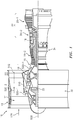
- FIG. 2 shows an HPC case section 38 of the core case 34 along the HPC.
- FIG. 2 schematically shows several stages of blades 40 of the HPC rotor. Interspersed with the blades are stages of stator vanes 42. Each blade has an airfoil 44 having a leading edge 46, a trailing edge 48, a pressure side (not shown) and a suction side (not shown) and extends from an inboard end to an outboard tip 50. The tip 50 is in close facing proximity to an inner diameter (ID) surface 52 of an outer airseal 54.
- Each exemplary outer airseal 54 includes a metallic substrate 56 and an abradable coating system (or rub strip) 58 ( FIG. 2A ) forming the ID surface 52 along an ID surface of the substrate.
- the exemplary outer airseal 54 is formed as a generally full annulus (e.g., locally interrupted by mounting features such as a circumferential array of holes 60 in a radially outwardly extending flange 62).
- the exemplary outer airseals 54 comprise an inboard body or band 64 comprising a body or band 66 of the substrate and the rub strip 58 inboard thereof.
- the flange 62 extends radially outward from the band 66.
- an axial collar portion 70 extends forwardly to terminate in a radially outward extending flange 72.
- the flange 72 has mounting holes 74 complementary to mounting holes of an adjacent mating flange.
- FIG. 2 shows several airseal stages associated with respective blade stages. Each flange 72 may mate to a flange 62 of the next forward airseal and be secured thereto via fasteners (e.g., threaded fasteners) 80.
- fasteners e.g., threaded fasteners
- FIG. 2A further shows respective fore and aft channels 90 and 92 outboard of corresponding cantilevered portions 94 and 96 of the substrate band 66 for capturing associated flanges of adjacent stages of stator segments.
- heat transfer to the flanges 62 and 72 is a source of problems. Steps that have been undertaken to address this include: making the flange 62 appropriately massive; and adding cooling features 68 such as those in the '494 application.
- the massiveness of the flange 62 functions in several ways. First, for a given amount of heat transfer to the band 66, and thus from the band to the flange 62, the temperature increase experienced by the flange will be smaller for more massive flanges. Second, a more massive flange 62 can more easily mechanically resist expansion caused by heating of the band 66 due to greater strength of the more massive flange.
- the rub strip 58 may be configured to influence heat transfer from the gaspath 510 ultimately to the flange 62.
- use of the rub strip to assist in thermal management may allow reduced massiveness of the flange and/or may allow reduction or elimination of cooling features such as those shown in the '494 application. Nevertheless, the thermal management associated with the rub strip 58 may be used in conjunction with such other features.
- the exemplary rub strip 58 ( FIG. 2A ) is located in an inwardly (radially) open annular channel 100 or well in the substrate band portion 66.
- the channel has a surface comprising a base surface 102 and respective fore and aft surfaces 104 and 106.
- the band 66 extends from a forward rim 108 to an aft rim 110 and has forwardmost and aftmost portions 112 and 114 respectively forward of and behind the channel 100.
- the rub strip 58 may be formed with multiple layers.
- a base layer 124 ( FIG. 2B ) may be a bondcoat atop an inner diameter (ID) surface portion of the substrate band formed by the channel surfaces (102, 104, 106).
- An optional thermal barrier coating (TBC) layer 126 is at least locally atop the bondcoat.
- An abradable layer 128 is at least locally atop the TBC layer (or atop the bondcoat if no TBC layer or otherwise positioned).
- the abradable layer 128 may represent modification of any appropriate prior art or future abradable layer composition but featuring matrix alloy discussed below.
- the TBC layer 126 if present, may be selected for insulative purposes to limit or tailor the flow of heat from the gaspath 510 to the substrate 56.
- the exemplary bondcoat 124 includes a base layer 130 and a thermally grown oxide (TGO) layer 132.
- the base layer and TGO layer may originally be deposited as a single precursor layer. There may be diffusion with the substrate.
- the TGO layer may reflect oxidation of original material of the precursor.
- Exemplary base layer thicknesses are 10-400 micrometers, more narrowly 20-200 micrometers.
- Exemplary TGO layer thicknesses are 0.05-1 micrometers, more narrowly 0.1-0.5 micrometers.
- Alternative bondcoats include diffusion aluminides.
- An exemplary coating process includes preparing the substrate (e.g., by cleaning and surface treating). A precursor of the bondcoat is applied.
- An exemplary application is of an MCrAlY, more particularly a NiCoCrAlY material.
- An exemplary MCrAlY is Ni 23Co 17Cr 12Al 0.5Y.
- An exemplary application is via a spray (e.g., a thermal spray) from a powder source.
- Exemplary application is via air plasma spray (APS).
- Alternative methods include a high-velocity oxy-fuel (HVOF) process, a high-velocity air-fuel (HVAF) process, a low pressure plasma spray (LPPS) process, or a wire-arc process.
- HVOF high-velocity oxy-fuel
- HVAC high-velocity air-fuel
- LPPS low pressure plasma spray
- An exemplary application is to a thickness of 0.003-0.010 inch, (76-254 micrometers) more broadly 0.001-0.015 inch (25-381 micrometers).
- the precursor may be diffused.
- An exemplary diffusion is via heating (e.g., to at least 1900°F (1038°C) for a duration of at least 4 hours) in vacuum or nonreactive (e.g., argon) atmosphere.
- the exemplary diffusion may create a metallurgical bond between the bondcoat and the substrate.
- diffusion steps may occur after applying the TBC, if at all.
- the substrate may be transferred to a coating apparatus for applying the TBC 126, if any, and abradable layer 128.
- An exemplary application is via a spray (e.g., a thermal spray) from a powder source.
- Exemplary application is via air plasma spray (APS).
- Alternative methods include a high-velocity oxy-fuel (HVOF) process, a high-velocity air-fuel (HVOF) process, a low pressure plasma spray (LPPS) process, or a wire-arc process.
- Alternative techniques involve consolidated and sintered powder including pressing, tape casting, and vibratory consolidation. These may include direct write, DMLS and laser fusing 3D printing with or without binders.
- pre-formed layers may be brazed or adhesively bonded or otherwise to the substrate (or to an intervening layer).
- An exemplary TBC 126 comprises a single ceramic-containing layer of a single nominal composition. Multi-layer and graded composition embodiments are also possible.
- An exemplary abradable layer 128 is a metal matrix composite.
- An exemplary metal matrix composite comprises the metal (alloy) matrix, a solid lubricant, and porosity.
- the exemplary TBC 126 contains metal (alloy) 140 and porosity 142 in addition to the ceramic 144.
- the exemplary by volume content of metal in the TBC is less than in the abradable layer.
- an exemplary ratio of ceramic 144 to metal 140 by volume is between 3:1 and 50:1, more particularly between 5:1 and 20:1 or between 5:1 and 10:1 or an exemplary about 7:1.
- An exemplary remainder e.g., porosity plus solid lubricant in some embodiments as discussed below
- 70% by volume more particularly 2% to 70%, or 5% to 60% or 20% to 50% or 30% to 45% or an exemplary about 40%.
- the ceramic 144 e.g., a stabilized zirconia such as a yttria-stabilized zirconia (YSZ), particularly 7YSZ
- the metal 140 greatly increases toughness and spallation resistance.
- Porosity if any created inherently by the application (e.g., spray) process and/or via addition of a fugitive filler material further reduces conductivity, but also contributes to reduced elastic modulus, coating stress and tendency to spall (i.e., both the metallic content and porosity increase the possible thickness of the TBC 126 and therefore maximum thermal resistance of the system).
- the TBC gets weak and allows abradable spallation. To mitigate this, the TBC may be selected to be stronger than the abradable.
- the exemplary abradable layer 128 contains metal (alloy) 150 and a solid lubricant 152. It may further contain porosity 154.
- a very broad range of relative contents of solid lubricant and porosity are possible in the abradable layer 128.
- an exemplary by volume content of the metal is 20% to 50%, more particularly 25% to 40%, or an exemplary about 35%.
- An exemplary porosity is up to 70% by volume, more particularly 1.0% to 70%, or 1.0% to 40%, or 1.0% to 30%; or 10% to 30% or 15% to 30% or an exemplary about 20% in embodiments that have significant porosity.
- Other embodiments may target low porosity (e.g., 0% to 10% or 1% to 6% or 2% to 4%) with high solid lubricant content.
- Exemplary solid lubricant 152 volumetric contents are at least 5% or at least 20% or an exemplary 20% to 60% in higher porosity layers and 60% to 80% or 70% to 80% or 75% to 80 % in the low porosity embodiments.
- porosity may be lower in the abradable layer than in the TBC (substantially lower in embodiments where the TBC or a main portion thereof does not include any of the solid lubricant but has only the ceramic, metal, and porosity). In either situation, the abradable layer would have lower cohesive bond strength than the TBC. In embodiments where the cohesive strength of the abradable layer is equal to or higher than that of the TBC, the risk of sheet spallation from the TBC would be unacceptable.
- Exemplary solid lubricants include hexagonal boron nitride (hBN) (e.g., commercially pure hBN or a mixture such as 10wt% bentonite agglomerated hBN).
- hBN hexagonal boron nitride
- the selection of porosity to hBN ratio may involve both engine operational requirements and economics.
- HBN is relatively expensive compared with porosity formers.
- high porosity coating versions will be lower cost to produce, the resultant roughness and porosity of the coating may cause greater aerodynamic losses than those with relatively lower porosity and higher hBN content.
- a binder material such as bentonite may be used to improve the deposition efficiency of the hBN.
- the benefit of improved aerodynamic efficiency greatly outweighs the added manufacturing cost of using high hBN content as opposed to porosity formers.
- the erosion resistance and abradability of a coating containing 28% by volume metal matrix may be desirable for a given application. If the coating were made with hBN content of about 70% and porosity of about 2%, the resultant coating would have low gas permeability and low surface roughness compared with a similar coating of high porosity. That high porosity coating would for example be 28% metal matrix plus 72% porosity after a fugitive constituent such as methylmethacrylate is burned out.
- a turbine compressor stage with the high hBN, relatively dense coating would have about 1% greater compressor stage efficiency than the porous version.
- hBN agglomerated with bentonite binder is used more efficiently in the thermal spray process.
- the pure hBN material is fused and crushed with irregular particle shape.
- the pure material also does not have a melting point under atmospheric conditions. This means that not only is the powder difficult to feed uniformly to the plasma spray process, but it does not melt to facilitate adhesion and deposition in the form of a coating.
- bentonite 5% to 15% of the hBN weight
- a slurry of the mixture can be made that can be spray dried into agglomerates that are substantially round and well suited to the powder feed methods used in thermal spray.
- agglomerates may be further heat treated to calcine the bentonite to drive off the water portion of the hydrated molecules that makeup the bentonite.
- This thermal treatment helps to make the agglomerates more durable to handling and reduces gas evolution during the heating of the thermal spray process.
- the bentonite component of the agglomerates melts and facilitates adhesion to form the coating.
- the resultant deposition process for the agglomerated hBN is about three times as efficient as for the pure crushed hBN.
- An exemplary ratio of abradable layer volumetric metal content to TBC volumetric metal content is between 1.5:1 and 15:1, more particularly between 2:1 and 10:1, or an exemplary 5:1.
- the metal (alloy) of the TBC is the same as that of the abradable.
- An exemplary alloy family is Cu-Ni-Cr-Al alloys. A particular alloy Cu40Ni7Cr7Al. Use of the same alloy across both layers has advantages of minimizing chances for galvanic corrosion and limiting differential thermal expansion and may otherwise aid inter-layer adhesion. Alternatives involve MCrAlY alloys.
- the metal (alloy) of the TBC is the same as that of the bondcoat (optionally different from that of the abradable layer). Similar advantages attend this as having the same alloy across the TBC and abradable layers.
- the aforementioned Cu40Ni7Cr7Al is one of several alloys believed to have advantageous properties for use in at least the abradable layer 128.
- Table I below lists several variations on this alloy among other candidates. The percentages are overall percentages in the deposited matrix and overall percentages in source material. When phases form in the deposited matrix, there will be variations in composition between the different phases.
- Table I Matrix Alloys (weight percentages) Element Cu Ni Al Cr Hf Si Y Al+Cr Ex. 1 Bal. 40 7 7 Ex. 2 Bal. 40 7 7 0.5 0.25 0.8 Ex. 3 Bal. 40 4 6.5 0.5 0.25 0.8 Ex. 4 Bal. 25 9 4 Ex. 5 Bal. 0 7 7 Range 1 Bal.
- Composition and processing parameters may be selected so that at 1200°F (649°C) the alloy has at least 10% by volume gamma prime (L12), bcc (alpha-Cr) (A2), and/or secondary fcc (A1) crystal structure and at most 10% by volume beta (B2) crystal structure.
- the primary phase will be fcc at a content of at least 50% by volume and typically close to the remainder.
- the primary fcc combined with the other listed phases may account for at least 98.0% by volume or at least 99.0%.
- Miscellaneous material including oxides may account for the rest.
- the ductility of the fcc phase (vs. hardness of B2) is advantageous when interfacing with a blade lacking an abrasive tip (i.e. the abradable coating interfaces directly with blade substrate superalloy).
- An exemplary nickel-based blade superalloy substrate is IN718.
- the hard B2 phase can wear the IN718 blade material and cause damage.
- the more ductile L12 intermetallic phase embedded in a soft Cu-fcc matrix is advantageous for interfacing with the blade substrate.
- advantageous features of these alloys are: they are ductile and tough to resist erosion and cracking in the operating temperature range; they have lower yield strength than blade substrate (e.g., IN718) at all operating temperatures; their strengths go to zero at their melting points well before the blade substrate; there are little to no phase changes over the operating temperature range to cause thermal cycle induced failure; they have good corrosion and oxidation resistance at operating temperature to protect the alloy itself.
- blade substrate e.g., IN718
- Exemplary matrix compositions have ductile multi-phase structure up to the onset of melting at about 1030-1040°C. This is about 300°C below the melting point of the blade substrate material (e.g., about 1300°C).
- exemplary rub temperature of 1200°F IN718 in one exemplary forged and aged condition has a yield strength (0.2% offset) of 132.5 ksi (914 MPa) and an ultimate tensile strength (UTS) of 150.0 ksi (1034 MPa).
- exemplary alloys might have a yield strength no more than 60 ksi (414 MPa) and a UTS of no more than 80 ksi (552 MPa) at said temperature, both being substantially lower than those of the substrate (e.g., more than 30% lower with some being at least 50% lower).
- the matrix alloy should not form an excess of intermetallic compounds which will reduce ductility and durability.
- the material may be particularly useful in addressing blade wear in relatively downstream stages of an HPC without adding abrasive blade tips while achieving good abradability and erosion resistance.
- the high temperature softness represents a substantial deviation from prior CoNiCrAlY abradable matrix that relied on weak interparticle bonding to achieve abradability.
- the table shows four nominal examples: Cu40Ni7Al7Cr; Cu40Ni4Al6.5Cr; Cu25Ni9Al4Cr; and Cu7Al7Cr.
- the first two are species of a high nickel content alloy; the third is an example of an intermediate nickel alloy; the fourth is an example of a low or no nickel alloy. As is discussed below, of these three, the high nickel alloy and low nickel alloy are believed advantageous in abradable applications.
- the table also shows a species of the first having specific amounts of Hf, Si and Y.
- the table shows several ranges around each of these three basic alloys.
- Ce, La, and Zr may also substitute for the Hf, Si, and/or Y.
- These six elements can add additional oxidation resistance, but must be limited to prevent excessive formation of intermetallic compounds that will harden and make the material more brittle. In some embodiments, these six elements may aggregate to ⁇ 3.5 weight % or ⁇ 3.0 weight % or ⁇ 2.5 weight % or ⁇ 2.0 weight %.
- the table also shows several ranges around combinations and subcombinations of the three basic alloys.
- Cu-40Ni-7Al-7Cr (nominal weight %) is derived to be a two-phase ductile alloy with very little or no third phase present.
- the two phases present are ductile fcc (disordered crystal structure) and L12 phases (ordered crystal structure).
- the center of the composition range of this alloy (ignoring impurities and additions) is Cu-37.9Ni-14.4Al-7.5Cr (atomic %).
- Having an Al+Cr content in excess of 20 atomic % guarantees that a stable adherent aluminia/chromia protective oxide layer forms when the alloy is exposed to temperatures in excess of 1200°F in an oxygen-rich environment such as a turbine engine compressor. Lower atomic percentages will still be effective (e.g., at least about 15%).
- the nominal Cu40Ni4Al6.5Cr has atomic % Al+Cr of about 16%.
- Cu-40Ni-7Al-7Cr and key alloys near it in the ranges above will have a high volume percent (more than 30%) of a ductile second strengthening phase (L12) in a ductile matrix (fcc).
- L12 ductile second strengthening phase
- fcc ductile matrix
- Cu-40Ni-7Al-7Cr (in weight %) is one composition actually produced and believed to be at or close to the upper Al and Cr limits of a particular range.
- a more ideal alloy in this range is Cu-40Ni-4Al-6.5Cr (in weight %). This is believed more remote from compositions that would develop undesirable embrittling phases such as B2.
- the alloy should have two major phases present (with little or no third phase): ductile fcc (disordered crystal structure) and L12 phases (ordered crystal structure).
- an exemplary substitution threshold is replacing up to 25% of the nickel or up to 10% as a lower threshold.
- the 25% and 10% examples may be applied to the combined iron and cobalt (even though behavior may be slightly more sensitive to iron content).
- Cu-25Ni-9Al-4Cr (nominal weight %) is derived to be a two-phase alloy with poorer ductility than Cu-40Ni-7Al-7Cr. In atomic percent, the center of the composition range of this alloy (ignoring impurities and additions) is Cu-23.5Ni-18.4Al-4.2Cr (atomic %).
- the high amount of Al and low amount of Ni can precipitate hard beta (B2) phase which can give it more brittle behavior. Desirable behavior would thus be obtained with lower Al and/or higher Ni.
- This alloy was produced to verify the predicted relatively poor behavior.
- This alloy is believed to have a relatively high volume percent (more than 30%) of a brittle strengthening phase (B2) in a ductile matrix (fcc).
- a lower Ni content than the first example lowers overall strength of alloy and stabilizes the B2 phase. This also relates to the greater upside tolerance of the first example to Cr vs. Al (the Al tending more to stabilize B2 at both given weight and atomic percent
- the Cu-7Al-7Cr (nominal weight %) is derived to be a two-phase ductile alloy with very little or no third phase present. In atomic percent, the alloy is Cu-14.9Al-7.7Cr (atomic %).
- the two phases present are ductile fcc (disordered crystal structure) and less ductile bcc-A2 phases (disordered crystal structure). Having an Al+Cr content in excess of 20 atomic % guarantees that a stable adherent aluminia/chromia protective oxide layer forms as above.
- Some embodiments may be characterized as having low volume percent (at 1200°F less than 15% or 5.0% to 10.0%) of the strengthening phase (bcc-A2) in a ductile matrix (fcc).
- the relative absence of Ni stabilizes the strengthening bcc-A2 phase.
- the embrittling B2 phase is believed avoided with either very low Ni or relatively high Ni contents.
- the specific Cu-7Al-7Cr composition is another desired composition representing the upper limits (Al and Cr combined) of a particular range. Within the range of 2.0-9.0 Al (weight %), 5.0-15.0 Cr, and balance Cu, the alloy should have two phases present (with little or no third phase): large amounts of ductile fcc (disordered crystal structure) and small amounts of bcc-A2 phases (disordered crystal structure).
- Hf, Si, and/or Y are highly reactive elements (RE) in the presence of oxygen and aid in the formation of an adherent protective oxide scale (the aforementioned alumina-chromia) during high temperature oxidation. Additionally, these reactive elements slow down the growth kinetics of the oxides which prevents excessive oxide growth. Excessive oxide growth can be detrimental to rub behavior.
- Hf, Si, and Y contents must be kept below about one weight % each or excessive growth of hafnium-oxide, silicon-oxide and yttrium-oxide can occur. Such growth competes with the alumina and chromia.
- the RE oxides have needle-like morphology and thus do not provide the protective barrier function of alumina and chromia.
- the alloys in the table above may be further defined by a combined Nb+Mo+Ta+W+Re content of less than or equal to 0.50 weight percent.
- An exemplary application process involves a thermal spray process (e.g., air plasma spray) in a single spray chamber to apply the TBC 126 and abradable layer 128.
- a thermal spray process e.g., air plasma spray
- a first premixed powder contains powders of the metal 140, ceramic 144, and a fugitive (e.g., polymeric such as an aromatic crystalline polyester or methyl methacrylate); and a second premixed powder contains powders of the metal 150, solid lubricant 154, and a fugitive (e.g., polymeric such as an aromatic crystalline polyester or methyl methacrylate).
- the spray torch may be switched between sources of the first powder and second powder to sequentially apply the TBC 126 and abradable layer 128.
- Post-spray bakeout may remove the fugitive to leave the porosity 142 and 154.
- An exemplary thickness of the TBC 126 is 0.010 inch to 0.080 inch (0.25 millimeter to 2.0 millimeter), more particularly, 0.020 inch to 0.060 inch (0.51 millimeter to 1.5 millimeter).
- An exemplary thickness of the abradable layer 128 is 0.010 inch (0.25 millimeter) to 0.16 inch (4.1 millimeters) or 0.020 inch (0.51 millimeter) to 0.10 inch (2.5 millimeters) or about 0.040 inch (1.0 millimeter) to 0.080 inch (2.0 millimeters).
- Depthwise transition zones may be present. For example, there may be a brief interval in a spray process when both the first powder source and second powder source are active.
- exemplary abradable thickness is 0.030 inch (0.76 millimeter) to 0.080 inch (2.0 millimeters).
- the abradable may be advantageous at layer thickness of as low as 0.015 inch (0.38 millimeter) or as thick as 0.300 inch (7.6 millimeters). This depends primarily on the size of the engine.
- a further variation involves a first source comprising the ceramic and optionally a fugitive and the second source comprising the metal, solid lubricant, and optionally fugitive.
- the first source and second source together are used to spray the TBC; the second source alone is used to spray the abradable layer.
- first, second, and the like in the following claims is for differentiation within the claim only and does not necessarily indicate relative or absolute importance or temporal order. Similarly, the identification in a claim of one element as “first” (or the like) does not preclude such "first” element from identifying an element that is referred to as “second” (or the like) in another claim or in the description.
Landscapes
- Engineering & Computer Science (AREA)
- Chemical & Material Sciences (AREA)
- Mechanical Engineering (AREA)
- Materials Engineering (AREA)
- Metallurgy (AREA)
- Organic Chemistry (AREA)
- General Engineering & Computer Science (AREA)
- General Chemical & Material Sciences (AREA)
- Manufacturing & Machinery (AREA)
- Chemical Kinetics & Catalysis (AREA)
- Structures Of Non-Positive Displacement Pumps (AREA)
- Coating By Spraying Or Casting (AREA)
- Turbine Rotor Nozzle Sealing (AREA)
Abstract
Description
- Benefit is claimed of
U.S. Patent Application No. 62/312,406, filed March 23, 2016 - This disclosure relates to a gas turbine engine, and more particularly to gaspath leakage seals for gas turbine engines.
- Gas turbine engines, such as those used to power modern commercial and military aircraft, generally include one or more compressor sections to pressurize an airflow, a combustor section for burning hydrocarbon fuel in the presence of the pressurized air, and one or more turbine sections to extract energy from the resultant combustion gases. The airflow flows along a gaspath through the gas turbine engine.
- The gas turbine engine includes a plurality of rotors arranged along an axis of rotation of the gas turbine engine. The rotors are positioned in a case, with the rotors and case having designed clearances between the case and tips of rotor blades of the rotors. It is desired to maintain the clearances within a selected range during operation of the gas turbine engine as deviation from the selected range can have a negative effect on gas turbine engine performance. For each blade stage, the case typically includes an outer airseal located in the case immediately outboard (radially) of the blade tips to aid in maintaining the clearances within the selected range.
- Within the compressor section(s), temperature typically progressively increases from upstream to downstream along the gaspath. Particularly, in relatively downstream stages, heating of the airseals becomes a problem.
US Patent Application No. 14/947,494, of Leslie et al. - The airseal typically has an abradable coating along its inner diameter (ID) surface. In relatively downstream stages of the compressor where the blades have nickel-based superalloy substrates, the abradable coating material may be applied to a bondcoat along the metallic substrate of the outer airseal. For relatively upstream sections where the compressor blades comprise titanium-based substrates (a potential source of fire) systems have been proposed with a fire-resistant thermal barrier layer intervening between the bondcoat and the abradable material. An example of such a coating is found in
US Patent No. 8,777,562 of Strock et al., issued July 15, 2014 and entitled "Blade Air Seal with Integral Barrier". - One aspect of the disclosure involves a blade outer airseal having a body. The body comprises: an inner diameter (ID) surface; an outer diameter (OD) surface; a leading end; and a trailing end. The airseal body has a metallic substrate and a coating system atop the substrate along at least a portion of the inner diameter surface. At least over a first area of the inner diameter surface, the coating system comprises an abradable layer comprising a metallic matrix and a solid lubricant. The metallic matrix (a) comprises, by weight, ≥35% copper, ≤45.0% nickel, 2.0-10.0% aluminum; and 3.0-15.0% chromium and/or (b) at 1200°F the metallic matrix has at least 10% by volume gamma prime (L12), bcc (A2), and/or secondary fcc (A1) crystal structure; and at most 10% by volume beta (B2) crystal structure.
- A further embodiment may additionally and/or alternatively involve a blade outer airseal (e.g. as herein described) having a body. The body comprises: an inner diameter (ID) surface; an outer diameter (OD) surface; a leading end; and a trailing end. The airseal body has a metallic substrate and a coating system atop the substrate along at least a portion of the inner diameter surface. At least over a first area of the inner diameter surface, the coating system comprises an abradable layer comprising a metallic matrix and a solid lubricant; and the metallic matrix comprises, by weight, ≥35% copper, 30.0-45.0% combined nickel, cobalt, and iron with combined iron and cobalt content at most one-third of the nickel content, 2.0-8.0% aluminum, and 5.0-15.0% chromium.
- A further embodiment may additionally and/or alternatively include the combined cobalt and iron contents of the metallic matrix being less than 5% by weight.
- A further embodiment may additionally and/or alternatively include, at 1200°F the metallic matrix having: at least 98% by volume fcc and L12 phases combined with at least 10% L12.
- A further embodiment may additionally and/or alternatively include the metallic matrix further comprising, by weight: no more than 5.0% combined of all other elements; and no more than 1.5% of any individual other element.
- A further embodiment may additionally and/or alternatively include the metallic matrix further comprising, by weight: no more than 0.5% combined of niobium, molybdenum, tantalum, tungsten, and rhenium.
- A further embodiment may additionally and/or alternatively include the metallic matrix further comprising, by weight: ≤1.0% hafnium; ≤1.0% silicon; and ≤1.0% yttrium.
- A further embodiment may additionally and/or alternatively include over the first area of the inner diameter surface, the coating system comprising the abradable layer and a thermal barrier layer between the abradable layer and the substrate.
- A further embodiment may additionally and/or alternatively include the abradable layer having a volume content of said solid lubricant of 5.0% to 80%.
- A further embodiment may additionally and/or alternatively include the solid lubricant comprising HBN.
- A further embodiment may additionally and/or alternatively include the abradable layer having a volume content of said metallic matrix of 20% to 50%.
- A further embodiment may additionally and/or alternatively include the abradable layer having less than 20% porosity.
- A further embodiment may additionally and/or alternatively include one or more of: the coating system having a bondcoat between the abradable layer and the substrate; and the substrate being a nickel-based superalloy.
- Another aspect of the disclosure involves a method for manufacturing the blade outer airseal (e.g. the blade outer airseal as herein described), the method comprising: thermal spray of the abradable layer.
- Another aspect of the disclosure involves a method for using the blade outer airseal (e.g. the blade outer airseal as herein described), the method comprising: installing the blade outer airseal on a turbine engine; and running the turbine engine so that blade tips rub the abradable coating.
- Another aspect of the disclosure involves a blade outer airseal (e.g. as herein described) having a body. The body comprises: an inner diameter (ID) surface; an outer diameter (OD) surface; a leading end; and a trailing end. The airseal body has a metallic substrate and a coating system atop the substrate along at least a portion of the inner diameter surface. At least over a first area of the inner diameter surface, the coating system comprises an abradable layer comprising a metallic matrix and a solid lubricant; and the metallic matrix comprises, by weight ≥80% copper, ≤10.0% nickel, 3.0-9.5% aluminum, and 3.0-10.0% chromium.
- A further embodiment may additionally and/or alternatively include at 1200°F the metallic matrix having by volume: at least 88% fcc phase; and 1% to 10% bcc (A2) phase.
- A further embodiment may additionally and/or alternatively include the metallic matrix further comprising, by weight: no more than 5.0% combined of all other elements; and no more than 1.5% of any individual other element.
- A further embodiment may additionally and/or alternatively include the metallic matrix further comprising, by weight: no more than 0.5% combined of niobium, molybdenum, tantalum, tungsten, and rhenium.
- A further embodiment may additionally and/or alternatively include the metallic matrix further comprising, by weight: ≤1.0% hafnium; ≤1.0% silicon; and ≤1.0% yttrium.
- Another aspect of the disclosure involves a blade outer airseal (e.g. as herein described) having a body. The body comprises: an inner diameter (ID) surface; an outer diameter (OD) surface; a leading end; and a trailing end. The airseal body has a metallic substrate and a coating system atop the substrate along at least a portion of the inner diameter surface. At least over a first area of the inner diameter surface, the coating system comprises an abradable layer comprising a metallic matrix and a solid lubricant; and at 1200°F the metallic matrix has: at least 40% primary fcc; at least 10% by volume gamma prime (L12), bcc (A2), and/or secondary fcc (A1) crystal structure; and at most 10% by volume beta (B2) crystal structure.
- A further embodiment may additionally and/or alternatively include a gas turbine engine compressor section comprising: a stage of blades having Ni-based substrates; and the blade outer airseal (e.g. as herein described) wherein the inner diameter (ID) surface faces tips of the blades.
- The details of one or more embodiments are set forth in the accompanying drawings and the description below. Other features, objects, and advantages will be apparent from the description and drawings, and from the claims.
-
-
FIG. 1 is a schematic axial half cross-sectional view of an embodiment of a gas turbine engine; -
FIG. 2 is a schematic axial cross-sectional view of an embodiment of a compressor of the gas turbine engine; -
FIG. 2A is a schematic axial cross-sectional view of an embodiment of an outer airseal of the compressor of the a gas turbine engine at detail 2A ofFIG. 2 ; -
FIG. 2B is a coating cross section atdetail 2B ofFIG. 2A . - Like reference numbers and designations in the various drawings indicate like elements.
-
FIG. 1 is a schematic illustration of agas turbine engine 10. The illustrated engine is a turbofan used to produce propulsive thrust in aerospace applications. Broadly, relevant gas turbine engines may also include turbojets, turboprops, industrial gas turbines (IGT), and the like. For purposes of illustration, outer aerodynamic cases are not shown. The gas turbine engine has a centrallongitudinal axis 500. The gas turbine engine generally has afan section 12 through which aninlet flow 520 of ambient air is propelled by afan 14, acompressor 16 for pressurizing the air 520-1 received from thefan 14, and acombustor 18 wherein the compressed air is mixed with fuel and ignited for generating combustion gases. Theinlet flow 520 splits into a first or core portion 520-1 flowing along the gaspath (core flowpath) 510 and a bypass portion 520-2 flowing along abypass flowpath 512. The illustratedengine 10 and gross features of its airseals (discussed below) are based on a particular configuration shown in the aforementioned '494 application. Nevertheless, the teachings herein may be applied to other general engine configurations and other general airseal configurations. - The
gas turbine engine 10 further comprises aturbine 20 for extracting energy from the combustion gases. Fuel is injected into thecombustor 18 of thegas turbine engine 10 for mixing with the compressed air from thecompressor 16 and ignition of the resultant mixture. Thefan 14,compressor 16,combustor 18, andturbine 20 are typically all concentric about a common centrallongitudinal axis 500 of thegas turbine engine 10. - Depending upon the implementation, the compressor and turbine may each contain multiple sections. Each section includes one or more stages of rotor blades interspersed with one or more stages of stator vanes. The exemplary configuration has two compressor sections and two turbine sections. From upstream to downstream along the
gaspath 510, these include a low pressure compressor section (LPC) 16-1, a high pressure compressor section (HPC) 16-2, a high pressure turbine section (HPT) 20-2, and a low pressure turbine section (LPT) 20-1. The exemplary rotors of the LPC and LPT are formed to rotate as a first unit or low pressure spool with the LPT driving the LPC. Similarly, the HPT and HPC rotors are arranged as a high pressure spool. The fan may be driven by the low pressure spool either directly or via areduction gearbox 30. Other configurations are, however, known. Whereas illustrated in the context ofcompressors 16, one skilled in the art will readily appreciate that the present disclosure may be utilized with respect to turbines (e.g., an LPT where temperatures are relatively low). - The exemplary engine comprises a
fan case 32 and acore case 34. The core case has sections along the corresponding sections of the engine core.FIG. 2 shows anHPC case section 38 of thecore case 34 along the HPC. -
FIG. 2 schematically shows several stages ofblades 40 of the HPC rotor. Interspersed with the blades are stages ofstator vanes 42. Each blade has anairfoil 44 having a leadingedge 46, a trailingedge 48, a pressure side (not shown) and a suction side (not shown) and extends from an inboard end to anoutboard tip 50. Thetip 50 is in close facing proximity to an inner diameter (ID) surface 52 of anouter airseal 54. Each exemplaryouter airseal 54 includes ametallic substrate 56 and an abradable coating system (or rub strip) 58 (FIG. 2A ) forming theID surface 52 along an ID surface of the substrate. - The exemplary
outer airseal 54 is formed as a generally full annulus (e.g., locally interrupted by mounting features such as a circumferential array ofholes 60 in a radially outwardly extending flange 62). In cross-section, the exemplaryouter airseals 54 comprise an inboard body orband 64 comprising a body orband 66 of the substrate and therub strip 58 inboard thereof. Theflange 62 extends radially outward from theband 66. For mounting the exemplary airseals, at a forward end of theflange 62, anaxial collar portion 70 extends forwardly to terminate in a radially outward extendingflange 72. Theflange 72 has mountingholes 74 complementary to mounting holes of an adjacent mating flange.FIG. 2 shows several airseal stages associated with respective blade stages. Eachflange 72 may mate to aflange 62 of the next forward airseal and be secured thereto via fasteners (e.g., threaded fasteners) 80. -
FIG. 2A further shows respective fore andaft channels portions 94 and 96 of thesubstrate band 66 for capturing associated flanges of adjacent stages of stator segments. - As is discussed in aforementioned '494 application, heat transfer to the
flanges flange 62 appropriately massive; and adding cooling features 68 such as those in the '494 application. The massiveness of theflange 62 functions in several ways. First, for a given amount of heat transfer to theband 66, and thus from the band to theflange 62, the temperature increase experienced by the flange will be smaller for more massive flanges. Second, a moremassive flange 62 can more easily mechanically resist expansion caused by heating of theband 66 due to greater strength of the more massive flange. - As is discussed below, however, the
rub strip 58 may be configured to influence heat transfer from thegaspath 510 ultimately to theflange 62. In various implementations, use of the rub strip to assist in thermal management may allow reduced massiveness of the flange and/or may allow reduction or elimination of cooling features such as those shown in the '494 application. Nevertheless, the thermal management associated with therub strip 58 may be used in conjunction with such other features. - The exemplary rub strip 58 (
FIG. 2A ) is located in an inwardly (radially) openannular channel 100 or well in thesubstrate band portion 66. The channel has a surface comprising abase surface 102 and respective fore andaft surfaces - The
band 66 extends from a forward rim 108 to anaft rim 110 and has forwardmost andaftmost portions channel 100. - The
rub strip 58 may be formed with multiple layers. A base layer 124 (FIG. 2B ) may be a bondcoat atop an inner diameter (ID) surface portion of the substrate band formed by the channel surfaces (102, 104, 106). An optional thermal barrier coating (TBC)layer 126 is at least locally atop the bondcoat. Anabradable layer 128 is at least locally atop the TBC layer (or atop the bondcoat if no TBC layer or otherwise positioned). Theabradable layer 128 may represent modification of any appropriate prior art or future abradable layer composition but featuring matrix alloy discussed below. TheTBC layer 126, if present, may be selected for insulative purposes to limit or tailor the flow of heat from thegaspath 510 to thesubstrate 56. - The
exemplary bondcoat 124 includes abase layer 130 and a thermally grown oxide (TGO)layer 132. The base layer and TGO layer may originally be deposited as a single precursor layer. There may be diffusion with the substrate. The TGO layer may reflect oxidation of original material of the precursor. Exemplary base layer thicknesses are 10-400 micrometers, more narrowly 20-200 micrometers. Exemplary TGO layer thicknesses are 0.05-1 micrometers, more narrowly 0.1-0.5 micrometers. Alternative bondcoats include diffusion aluminides. - An exemplary coating process includes preparing the substrate (e.g., by cleaning and surface treating). A precursor of the bondcoat is applied. An exemplary application is of an MCrAlY, more particularly a NiCoCrAlY material. An exemplary MCrAlY is Ni 23Co 17Cr 12Al 0.5Y. An exemplary application is via a spray (e.g., a thermal spray) from a powder source. Exemplary application is via air plasma spray (APS). Alternative methods include a high-velocity oxy-fuel (HVOF) process, a high-velocity air-fuel (HVAF) process, a low pressure plasma spray (LPPS) process, or a wire-arc process.
- An exemplary application is to a thickness of 0.003-0.010 inch, (76-254 micrometers) more broadly 0.001-0.015 inch (25-381 micrometers).
- After the application, the precursor may be diffused. An exemplary diffusion is via heating (e.g., to at least 1900°F (1038°C) for a duration of at least 4 hours) in vacuum or nonreactive (e.g., argon) atmosphere. The exemplary diffusion may create a metallurgical bond between the bondcoat and the substrate. Alternatively diffusion steps may occur after applying the TBC, if at all.
- After application of the bondcoat precursor, if any, the substrate may be transferred to a coating apparatus for applying the
TBC 126, if any, andabradable layer 128. An exemplary application is via a spray (e.g., a thermal spray) from a powder source. Exemplary application is via air plasma spray (APS). Alternative methods include a high-velocity oxy-fuel (HVOF) process, a high-velocity air-fuel (HVOF) process, a low pressure plasma spray (LPPS) process, or a wire-arc process. Alternative techniques involve consolidated and sintered powder including pressing, tape casting, and vibratory consolidation. These may include direct write, DMLS and laser fusing 3D printing with or without binders. As an alternative to in situ formation directly on the substrate (optionally with a bond coat or other layer(s)) pre-formed layers may be brazed or adhesively bonded or otherwise to the substrate (or to an intervening layer). - An
exemplary TBC 126 comprises a single ceramic-containing layer of a single nominal composition. Multi-layer and graded composition embodiments are also possible. An exemplaryabradable layer 128 is a metal matrix composite. An exemplary metal matrix composite comprises the metal (alloy) matrix, a solid lubricant, and porosity. - The
exemplary TBC 126 contains metal (alloy) 140 andporosity 142 in addition to the ceramic 144. The exemplary by volume content of metal in the TBC is less than in the abradable layer. - Within the
TBC 126, an exemplary ratio of ceramic 144 tometal 140 by volume is between 3:1 and 50:1, more particularly between 5:1 and 20:1 or between 5:1 and 10:1 or an exemplary about 7:1. An exemplary remainder (e.g., porosity plus solid lubricant in some embodiments as discussed below) is up to 70% by volume, more particularly 2% to 70%, or 5% to 60% or 20% to 50% or 30% to 45% or an exemplary about 40%. - The ceramic 144 (e.g., a stabilized zirconia such as a yttria-stabilized zirconia (YSZ), particularly 7YSZ) contributes to the composite low conductivity and strength. The
metal 140 greatly increases toughness and spallation resistance. Porosity (if any) created inherently by the application (e.g., spray) process and/or via addition of a fugitive filler material further reduces conductivity, but also contributes to reduced elastic modulus, coating stress and tendency to spall (i.e., both the metallic content and porosity increase the possible thickness of theTBC 126 and therefore maximum thermal resistance of the system). At some point with increasing porosity the TBC gets weak and allows abradable spallation. To mitigate this, the TBC may be selected to be stronger than the abradable. - The exemplary
abradable layer 128 contains metal (alloy) 150 and asolid lubricant 152. It may further containporosity 154. - A very broad range of relative contents of solid lubricant and porosity are possible in the
abradable layer 128. Within theabradable layer 128, an exemplary by volume content of the metal is 20% to 50%, more particularly 25% to 40%, or an exemplary about 35%. An exemplary porosity is up to 70% by volume, more particularly 1.0% to 70%, or 1.0% to 40%, or 1.0% to 30%; or 10% to 30% or 15% to 30% or an exemplary about 20% in embodiments that have significant porosity. Other embodiments may target low porosity (e.g., 0% to 10% or 1% to 6% or 2% to 4%) with high solid lubricant content. Exemplarysolid lubricant 152 volumetric contents are at least 5% or at least 20% or an exemplary 20% to 60% in higher porosity layers and 60% to 80% or 70% to 80% or 75% to 80 % in the low porosity embodiments. - In the low porosity abradable layer embodiments, porosity may be lower in the abradable layer than in the TBC (substantially lower in embodiments where the TBC or a main portion thereof does not include any of the solid lubricant but has only the ceramic, metal, and porosity). In either situation, the abradable layer would have lower cohesive bond strength than the TBC. In embodiments where the cohesive strength of the abradable layer is equal to or higher than that of the TBC, the risk of sheet spallation from the TBC would be unacceptable.
- Exemplary solid lubricants include hexagonal boron nitride (hBN) (e.g., commercially pure hBN or a mixture such as 10wt% bentonite agglomerated hBN). The selection of porosity to hBN ratio may involve both engine operational requirements and economics. HBN is relatively expensive compared with porosity formers. Whereas high porosity coating versions will be lower cost to produce, the resultant roughness and porosity of the coating may cause greater aerodynamic losses than those with relatively lower porosity and higher hBN content. In order to improve the economics of low porosity, high hBN coatings, a binder material such as bentonite may be used to improve the deposition efficiency of the hBN.
- In many aerospace applications the benefit of improved aerodynamic efficiency greatly outweighs the added manufacturing cost of using high hBN content as opposed to porosity formers. For example, the erosion resistance and abradability of a coating containing 28% by volume metal matrix may be desirable for a given application. If the coating were made with hBN content of about 70% and porosity of about 2%, the resultant coating would have low gas permeability and low surface roughness compared with a similar coating of high porosity. That high porosity coating would for example be 28% metal matrix plus 72% porosity after a fugitive constituent such as methylmethacrylate is burned out. A turbine compressor stage with the high hBN, relatively dense coating, would have about 1% greater compressor stage efficiency than the porous version. This 1% efficiency difference provides thousands of dollars' worth of fuel savings over the life of an engine. In contrast, the added manufacturing cost may be on the order of a few hundred dollars. In contrast, in the land based industrial gas turbine (IGT) industry, turbine diameter is relatively large. As diameter increases, power increases faster as a function of diameter increase than do the surface roughness aerodynamic losses around the outer diameter of the turbine. Thus, the efficiency of the larger diameter IGT turbines is less sensitive to the surface aerodynamic losses. With the high emphasis on low initial cost in the IGT industry, the less expensive high porosity version of the abrdable is likely to be chosen.
- Even in the high porosity coating versions it is desirable to include at least some solid lubricant phase, on the order of 5% by volume. The solid lubricant contributes to particle liberation during rub events. In contrast, with no solid lubricant, there is an increased tendency for metal smearing that creates a fully dense metal layer on the abradable. When this occurs, blade wear increases and abradability is diminished.
- In comparison with fused and crushed pure hBN, hBN agglomerated with bentonite binder is used more efficiently in the thermal spray process. The pure hBN material is fused and crushed with irregular particle shape. The pure material also does not have a melting point under atmospheric conditions. This means that not only is the powder difficult to feed uniformly to the plasma spray process, but it does not melt to facilitate adhesion and deposition in the form of a coating. With the addition of bentonite to hBN (5% to 15% of the hBN weight), a slurry of the mixture can be made that can be spray dried into agglomerates that are substantially round and well suited to the powder feed methods used in thermal spray. These agglomerates may be further heat treated to calcine the bentonite to drive off the water portion of the hydrated molecules that makeup the bentonite. This thermal treatment helps to make the agglomerates more durable to handling and reduces gas evolution during the heating of the thermal spray process. During the thermal spray process, most desirably air plasma spray, the bentonite component of the agglomerates melts and facilitates adhesion to form the coating. The resultant deposition process for the agglomerated hBN is about three times as efficient as for the pure crushed hBN.
- An exemplary ratio of abradable layer volumetric metal content to TBC volumetric metal content is between 1.5:1 and 15:1, more particularly between 2:1 and 10:1, or an exemplary 5:1. In one group of examples, the metal (alloy) of the TBC is the same as that of the abradable. An exemplary alloy family is Cu-Ni-Cr-Al alloys. A particular alloy Cu40Ni7Cr7Al. Use of the same alloy across both layers has advantages of minimizing chances for galvanic corrosion and limiting differential thermal expansion and may otherwise aid inter-layer adhesion. Alternatives involve MCrAlY alloys.
- In another group of examples, the metal (alloy) of the TBC is the same as that of the bondcoat (optionally different from that of the abradable layer). Similar advantages attend this as having the same alloy across the TBC and abradable layers.
- The aforementioned Cu40Ni7Cr7Al is one of several alloys believed to have advantageous properties for use in at least the
abradable layer 128. Table I below lists several variations on this alloy among other candidates. The percentages are overall percentages in the deposited matrix and overall percentages in source material. When phases form in the deposited matrix, there will be variations in composition between the different phases.Table I Matrix Alloys (weight percentages) Element Cu Ni Al Cr Hf Si Y Al+Cr Ex. 1 Bal. 40 7 7 Ex. 2 Bal. 40 7 7 0.5 0.25 0.8 Ex. 3 Bal. 40 4 6.5 0.5 0.25 0.8 Ex. 4 Bal. 25 9 4 Ex. 5 Bal. 0 7 7 Range 1 Bal. 30.0-45.0 2.0-8.0 5.0-15.0 ≤1.0 ≤1.0 ≤1.5 8.0-20.0 Range 2 Bal. 35.0-43.0 3.0-8.0 5.0-9.0 ≤1.0 ≤1.0 ≤1.5 10.0-16.0 Range 3 Bal. 38.0-42.0 3.5-7.5 6.0-8.0 ≤1.0 ≤1.0 ≤1.5 10.0-15.0 Range 4 Bal. 35.0-42.0 3.5-5.0 6.0-7.0 ≤1.0 ≤1.0 ≤1.5 10.0-12.0 Range 5 Bal. ≤10.0 3.0-9.5 3.0-10.0 ≤1.0 ≤1.0 ≤1.5 9.0-16.0 Range 6 Bal. ≤5.0 3.0-8.0 3-10 ≤1.0 ≤1.0 ≤1.5 9.0-16.0 Range 7 Bal. ≤5.0 5.0-8.0 5.0-9.0 ≤1.0 ≤1.0 ≤1.5 9.0-16.0 Range 8 Bal. ≤3.0 5.0-8.0 5.0-9.0 ≤1.0 ≤1.0 ≤1.5 9.0-14.0 - Composition and processing parameters may be selected so that at 1200°F (649°C) the alloy has at least 10% by volume gamma prime (L12), bcc (alpha-Cr) (A2), and/or secondary fcc (A1) crystal structure and at most 10% by volume beta (B2) crystal structure. The primary phase will be fcc at a content of at least 50% by volume and typically close to the remainder. For example, the primary fcc combined with the other listed phases may account for at least 98.0% by volume or at least 99.0%. Miscellaneous material including oxides may account for the rest.
- The ductility of the fcc phase (vs. hardness of B2) is advantageous when interfacing with a blade lacking an abrasive tip (i.e. the abradable coating interfaces directly with blade substrate superalloy). An exemplary nickel-based blade superalloy substrate is IN718.
- With traditional CoNiCrAlY abradables, during the rub event, the hard B2 phase can wear the IN718 blade material and cause damage. The more ductile L12 intermetallic phase embedded in a soft Cu-fcc matrix is advantageous for interfacing with the blade substrate. These phases are similar to those present in the blade superalloy but are mechanically weaker to prevent damage to the blade material.
- In one or more embodiments, advantageous features of these alloys are: they are ductile and tough to resist erosion and cracking in the operating temperature range; they have lower yield strength than blade substrate (e.g., IN718) at all operating temperatures; their strengths go to zero at their melting points well before the blade substrate; there are little to no phase changes over the operating temperature range to cause thermal cycle induced failure; they have good corrosion and oxidation resistance at operating temperature to protect the alloy itself.
- Exemplary matrix compositions have ductile multi-phase structure up to the onset of melting at about 1030-1040°C. This is about 300°C below the melting point of the blade substrate material (e.g., about 1300°C).
- At one exemplary rub temperature of 1200°F, IN718 in one exemplary forged and aged condition has a yield strength (0.2% offset) of 132.5 ksi (914 MPa) and an ultimate tensile strength (UTS) of 150.0 ksi (1034 MPa). To interface with such a substrate, exemplary alloys might have a yield strength no more than 60 ksi (414 MPa) and a UTS of no more than 80 ksi (552 MPa) at said temperature, both being substantially lower than those of the substrate (e.g., more than 30% lower with some being at least 50% lower).
- In addition to melting point below that of the blade substrate, the matrix alloy should not form an excess of intermetallic compounds which will reduce ductility and durability.
- The material may be particularly useful in addressing blade wear in relatively downstream stages of an HPC without adding abrasive blade tips while achieving good abradability and erosion resistance. The high temperature softness represents a substantial deviation from prior CoNiCrAlY abradable matrix that relied on weak interparticle bonding to achieve abradability.
- The table shows four nominal examples: Cu40Ni7Al7Cr; Cu40Ni4Al6.5Cr; Cu25Ni9Al4Cr; and Cu7Al7Cr. The first two are species of a high nickel content alloy; the third is an example of an intermediate nickel alloy; the fourth is an example of a low or no nickel alloy. As is discussed below, of these three, the high nickel alloy and low nickel alloy are believed advantageous in abradable applications.
- The table also shows a species of the first having specific amounts of Hf, Si and Y.
- The table shows several ranges around each of these three basic alloys. Ce, La, and Zr may also substitute for the Hf, Si, and/or Y. These six elements can add additional oxidation resistance, but must be limited to prevent excessive formation of intermetallic compounds that will harden and make the material more brittle. In some embodiments, these six elements may aggregate to ≤3.5 weight % or ≤3.0 weight % or ≤2.5 weight % or ≤2.0 weight %.
- The table also shows several ranges around combinations and subcombinations of the three basic alloys.
- For each of these basic alloys or ranges, further variations may include limits on Nb+Mo+Ta+W+Re (e.g., ≤0.5) and/or elements other than those listed (e.g., also ≤0.5).
- Properties of the specific examples and families are discussed below. Cu-40Ni-7Al-7Cr (nominal weight %) is derived to be a two-phase ductile alloy with very little or no third phase present. The two phases present are ductile fcc (disordered crystal structure) and L12 phases (ordered crystal structure). In atomic percent, the center of the composition range of this alloy (ignoring impurities and additions) is Cu-37.9Ni-14.4Al-7.5Cr (atomic %). Having an Al+Cr content in excess of 20 atomic % guarantees that a stable adherent aluminia/chromia protective oxide layer forms when the alloy is exposed to temperatures in excess of 1200°F in an oxygen-rich environment such as a turbine engine compressor. Lower atomic percentages will still be effective (e.g., at least about 15%). For example, the nominal Cu40Ni4Al6.5Cr has atomic % Al+Cr of about 16%.
- Cu-40Ni-7Al-7Cr and key alloys near it in the ranges above will have a high volume percent (more than 30%) of a ductile second strengthening phase (L12) in a ductile matrix (fcc). The high Ni content provides additional strength and stabilizes the L12 phase.
- Cu-40Ni-7Al-7Cr (in weight %) is one composition actually produced and believed to be at or close to the upper Al and Cr limits of a particular range. A more ideal alloy in this range is Cu-40Ni-4Al-6.5Cr (in weight %). This is believed more remote from compositions that would develop undesirable embrittling phases such as B2. Within the range of 30-45 Ni (in weight %), 2.0-8.0 Al, 5.0-15.0 Cr and balance Cu, the alloy should have two major phases present (with little or no third phase): ductile fcc (disordered crystal structure) and L12 phases (ordered crystal structure).
- It may be possible to substitute in a moderate amount of cobalt for some of the nickel. In general, these have certain similarities in affecting phase stabilities. Beyond some threshold, differences between cobalt and nickel may become relevant with cobalt tending to stabilize undesirable phases. Thus, an exemplary substitution threshold is replacing up to 25% of the nickel or up to 10% as a lower threshold. Similarly, there may be an iron substitution. Thus, the 25% and 10% examples may be applied to the combined iron and cobalt (even though behavior may be slightly more sensitive to iron content).
- Cu-25Ni-9Al-4Cr (nominal weight %) is derived to be a two-phase alloy with poorer ductility than Cu-40Ni-7Al-7Cr. In atomic percent, the center of the composition range of this alloy (ignoring impurities and additions) is Cu-23.5Ni-18.4Al-4.2Cr (atomic %). The high amount of Al and low amount of Ni can precipitate hard beta (B2) phase which can give it more brittle behavior. Desirable behavior would thus be obtained with lower Al and/or higher Ni. This alloy was produced to verify the predicted relatively poor behavior. This alloy is believed to have a relatively high volume percent (more than 30%) of a brittle strengthening phase (B2) in a ductile matrix (fcc). A lower Ni content than the first example lowers overall strength of alloy and stabilizes the B2 phase. This also relates to the greater upside tolerance of the first example to Cr vs. Al (the Al tending more to stabilize B2 at both given weight and atomic percent).
- The Cu-7Al-7Cr (nominal weight %) is derived to be a two-phase ductile alloy with very little or no third phase present. In atomic percent, the alloy is Cu-14.9Al-7.7Cr (atomic %). The two phases present are ductile fcc (disordered crystal structure) and less ductile bcc-A2 phases (disordered crystal structure). Having an Al+Cr content in excess of 20 atomic % guarantees that a stable adherent aluminia/chromia protective oxide layer forms as above.
- Some embodiments may be characterized as having low volume percent (at 1200°F less than 15% or 5.0% to 10.0%) of the strengthening phase (bcc-A2) in a ductile matrix (fcc). The relative absence of Ni stabilizes the strengthening bcc-A2 phase. The embrittling B2 phase is believed avoided with either very low Ni or relatively high Ni contents.
- The specific Cu-7Al-7Cr composition is another desired composition representing the upper limits (Al and Cr combined) of a particular range. Within the range of 2.0-9.0 Al (weight %), 5.0-15.0 Cr, and balance Cu, the alloy should have two phases present (with little or no third phase): large amounts of ductile fcc (disordered crystal structure) and small amounts of bcc-A2 phases (disordered crystal structure).
- In the various alloys, there may be additions of Hf, Si, and/or Y (or the Ce, La, and/or Zr noted above and subject to similar limits). Hf, Si, and Y are highly reactive elements (RE) in the presence of oxygen and aid in the formation of an adherent protective oxide scale (the aforementioned alumina-chromia) during high temperature oxidation. Additionally, these reactive elements slow down the growth kinetics of the oxides which prevents excessive oxide growth. Excessive oxide growth can be detrimental to rub behavior. However, Hf, Si, and Y contents must be kept below about one weight % each or excessive growth of hafnium-oxide, silicon-oxide and yttrium-oxide can occur. Such growth competes with the alumina and chromia. The RE oxides have needle-like morphology and thus do not provide the protective barrier function of alumina and chromia.
- Additions of refractory elements can precipitate other brittle phases which are detrimental to rub behavior. Thus, as noted above, the alloys in the table above may be further defined by a combined Nb+Mo+Ta+W+Re content of less than or equal to 0.50 weight percent.
- An exemplary application process involves a thermal spray process (e.g., air plasma spray) in a single spray chamber to apply the
TBC 126 andabradable layer 128. In one group of examples: a first premixed powder contains powders of themetal 140, ceramic 144, and a fugitive (e.g., polymeric such as an aromatic crystalline polyester or methyl methacrylate); and a second premixed powder contains powders of themetal 150,solid lubricant 154, and a fugitive (e.g., polymeric such as an aromatic crystalline polyester or methyl methacrylate). The spray torch may be switched between sources of the first powder and second powder to sequentially apply theTBC 126 andabradable layer 128. Post-spray bakeout may remove the fugitive to leave theporosity - An exemplary thickness of the
TBC 126 is 0.010 inch to 0.080 inch (0.25 millimeter to 2.0 millimeter), more particularly, 0.020 inch to 0.060 inch (0.51 millimeter to 1.5 millimeter). An exemplary thickness of theabradable layer 128 is 0.010 inch (0.25 millimeter) to 0.16 inch (4.1 millimeters) or 0.020 inch (0.51 millimeter) to 0.10 inch (2.5 millimeters) or about 0.040 inch (1.0 millimeter) to 0.080 inch (2.0 millimeters). Depthwise transition zones may be present. For example, there may be a brief interval in a spray process when both the first powder source and second powder source are active. In situations without theTBC layer 126, exemplary abradable thickness is 0.030 inch (0.76 millimeter) to 0.080 inch (2.0 millimeters). In some examples the abradable may be advantageous at layer thickness of as low as 0.015 inch (0.38 millimeter) or as thick as 0.300 inch (7.6 millimeters). This depends primarily on the size of the engine. - A further variation involves a first source comprising the ceramic and optionally a fugitive and the second source comprising the metal, solid lubricant, and optionally fugitive. The first source and second source together are used to spray the TBC; the second source alone is used to spray the abradable layer. There may be a graded transition as flow from the first source is decreased and/or the second source is increased. As mentioned above, this allows some of the porosity found in a TBC lacking the solid lubricant to be filled with the solid lubricant. Providing the graded transition or allowing the TBC to include the solid lubricant is not believed to have performance advantages but may have manufacturing economy advantages.
- The use of "first", "second", and the like in the following claims is for differentiation within the claim only and does not necessarily indicate relative or absolute importance or temporal order. Similarly, the identification in a claim of one element as "first" (or the like) does not preclude such "first" element from identifying an element that is referred to as "second" (or the like) in another claim or in the description.
- Where a measure is given in English units followed by a parenthetical containing SI or other units, the parenthetical's units are a conversion and should not imply a degree of precision not found in the English units.
- One or more embodiments have been described. Nevertheless, it will be understood that various modifications may be made. For example, when applied to an existing baseline configuration, details of such baseline may influence details of particular implementations. Accordingly, other embodiments are within the scope of the following claims.
- Certain preferred embodiments of the present disclosure are as follows:
- 1. A blade outer airseal having:
- a body comprising:
- an inner diameter (ID) surface;
- an outer diameter (OD) surface;
- a leading end;
- a trailing end;
- a metallic substrate; and
- a coating system atop the substrate along at least a portion of the inner diameter surface,
- at least over a first area of the inner diameter surface, the coating system comprises an abradable layer comprising a metallic matrix and a solid lubricant; and
- the metallic matrix comprises, by weight:
- ≥35% copper;
- 30.0-45.0% combined nickel, cobalt, and iron with combined iron and cobalt content at most one-third of the nickel content;
- 2.0-8.0% aluminum; and
- 5.0-15.0% chromium.
- a body comprising:
- 2. The blade outer airseal of embodiment 1 wherein the combined cobalt and iron contents of the metallic matrix are less than 5% by weight.
- 3. The blade outer airseal of embodiment 1 wherein at 1200°F the metallic matrix has:
- at least 98% by volume fcc and L12 phases combined with at least 10% L12.
- 4. The blade outer airseal of embodiment 1 wherein the metallic matrix further comprises, by weight:
- no more than 5.0% combined of all other elements; and
- no more than 1.5% of any individual other element.
- 5. The blade outer airseal of embodiment 1 wherein the metallic matrix further comprises, by weight:
- no more than 0.5% combined of niobium, molybdenum, tantalum, tungsten, and rhenium.
- 6. The blade outer airseal of embodiment 1 wherein the metallic matrix further comprises, by weight:
- ≤1.0% hafnium;
- ≤1.0% silicon; and
- ≤1.0% yttrium.
- 7. The blade outer airseal of embodiment 1 wherein:
- over the first area of the inner diameter surface, the coating system comprises the abradable layer and a thermal barrier layer between the abradable layer and the substrate.
- 8. The blade outer airseal of embodiment 1 wherein:
- the abradable layer has a volume content of said solid lubricant of 5.0% to 80%.
- 9. The blade outer airseal of embodiment 1 wherein:
- the solid lubricant comprises HBN.
- 10. The blade outer airseal of embodiment 1 wherein:
- the abradable layer has a volume content of said metallic matrix of 20% to 50%.
- 11. The blade outer airseal of embodiment 1 wherein:
- the abradable layer has less than 20% porosity.
- 12. The blade outer airseal of embodiment 1 wherein one or more of:
- the coating system has a bondcoat between the abradable layer and the substrate; and
- the substrate is a nickel-based superalloy.
- 13. A method for manufacturing the blade outer airseal of embodiment 1, the method comprising:
- thermal spray of the abradable layer.
- 14. A method for using the blade outer airseal of embodiment 1, the method comprising:
- installing the blade outer airseal on a turbine engine; and
- running the turbine engine so that blade tips rub the abradable coating.
- 15. A blade outer airseal having:
- a body comprising:
- an inner diameter (ID) surface;
- an outer diameter (OD) surface;
- a leading end;
- a trailing end;
- a metallic substrate; and
- a coating system atop the substrate along at least a portion of the inner diameter surface,
- at least over a first area of the inner diameter surface, the coating system comprises an abradable layer comprising a metallic matrix and a solid lubricant; and
- the metallic matrix comprises, by weight:
- ≥80% copper;
- ≤10.0% nickel;
- 3.0-9.5% aluminum; and
- 3.0-10.0% chromium.
- a body comprising:
- 16. The blade outer airseal of embodiment 0 wherein at 1200°F the metallic matrix has by volume:
- at least 88% fcc phase; and
- 1% to 10% bcc (A2) phase.
- 17. The blade outer airseal of embodiment 0 wherein the metallic matrix further comprises, by weight:
- no more than 5.0% combined of all other elements; and
- no more than 1.5% of any individual other element.
- 18. The blade outer airseal of embodiment 0 wherein the metallic matrix further comprises, by weight:
- no more than 0.5% combined of niobium, molybdenum, tantalum, tungsten, and rhenium.
- 19. The blade outer airseal of embodiment 0 wherein the metallic matrix further comprises, by weight:
- ≤1.0% hafnium;
- ≤1.0% silicon; and
- ≤1.0% yttrium.
- 20. A blade outer airseal having:
- a body comprising:
- an inner diameter (ID) surface;
- an outer diameter (OD) surface;
- a leading end;
- a trailing end;
- a metallic substrate; and
- a coating system atop the substrate along at least a portion of the inner diameter surface,
- at least over a first area of the inner diameter surface, the coating system comprises an abradable layer comprising a metallic matrix and a solid lubricant; and
- at 1200°F the metallic matrix has:
- at least 40% primary fcc;
- at least 10% by volume gamma prime (L12), bcc (A2), and/or secondary fcc (A1) crystal structure; and at most 10% by volume beta (B2) crystal structure.
- a body comprising:
- 21. A gas turbine engine compressor section comprising:
- a stage of blades having Ni-based substrates; and
- the blade outer airseal of embodiment 0 wherein the inner diameter (ID) surface faces tips of the blades.
Claims (15)
- A blade outer airseal having:a body comprising:wherein:an inner diameter (ID) surface;an outer diameter (OD) surface;a leading end;a trailing end;a metallic substrate; anda coating system atop the substrate along at least a portion of the inner diameter surface,(a) at least over a first area of the inner diameter surface, the coating system comprises an abradable layer comprising a metallic matrix and a solid lubricant; andthe metallic matrix comprises, by weight:≥35% copper;≤ 45% nickel;2.0-10.0% aluminum; and3.0-15.0% chromium;and/or(b) at least over a first area of the inner diameter surface, the coating system comprises an abradable layer comprising a metallic matrix and a solid lubricant; and at 649 °C (1200°F) the metallic matrix has:at least 40% primary fcc;at least 10% by volume gamma prime (L12), bcc (A2), and/or secondary fcc (A1) crystal structure; andat most 10% by volume beta (B2) crystal structure.
- The blade outer airseal of claim 1 wherein the metallic matrix comprises, by weight:≥35% copper;30.0-45.0% combined nickel, cobalt, and iron with combined iron and cobalt content at most one-third of the nickel content;2.0-8.0% aluminum; and5.0-15.0% chromium.
- The blade outer airseal of claim 2 wherein the combined cobalt and iron contents of the metallic matrix are less than 5% by weight.
- The blade outer airseal of claim 1 wherein the metallic matrix comprises, by weight:≥80% copper;≤10% nickel;3.0-9.5% aluminum; and3.0-10.0% chromium.
- The blade outer airseal of any preceding claim wherein at 649 °C (1200°F) the metallic matrix has:at least 98% by volume fcc and L12 phases combined with at least 10% L12, orat least 88% fcc phase and1% to 10% bcc (A2) phase.
- The blade outer airseal of any preceding claim wherein the metallic matrix further comprises, by weight:no more than 5.0% combined of all other elements; andno more than 1.5% of any individual other element.
- The blade outer airseal of any preceding claim wherein the metallic matrix further comprises, by weight:no more than 0.5% combined of niobium, molybdenum, tantalum, tungsten, and rhenium.
- The blade outer airseal of any preceding claim wherein the metallic matrix further comprises, by weight:≤1.0% hafnium;≤1.0% silicon; and≤1.0% yttrium.
- The blade outer airseal of any preceding claim wherein:over the first area of the inner diameter surface, the coating system comprises the abradable layer and a thermal barrier layer between the abradable layer and the substrate.
- The blade outer airseal of any preceding claim wherein:the abradable layer has a volume content of said solid lubricant of 5.0% to 80%, and/or wherein the solid lubricant comprises HBN.
- The blade outer airseal of any preceding claim wherein:the abradable layer has a volume content of said metallic matrix of 20% to 50%, and/or wherein the abradable layer has less than 20% porosity.
- The blade outer airseal of any preceding claim wherein one or more of:the coating system has a bondcoat between the abradable layer and the substrate; andthe substrate is a nickel-based superalloy.
- A method for manufacturing the blade outer airseal of any preceding claim, the method comprising:thermal spray of the abradable layer.
- A method for using the blade outer airseal of any preceding claim, the method comprising:installing the blade outer airseal on a turbine engine; andrunning the turbine engine so that blade tips rub the abradable coating.
- A gas turbine engine compressor section comprising:a stage of blades having Ni-based substrates; andthe blade outer airseal of any one of claims 1 to 12 wherein the inner diameter (ID) surface faces tips of the blades.
Priority Applications (1)
| Application Number | Priority Date | Filing Date | Title |
|---|---|---|---|
| EP19195223.3A EP3604742B8 (en) | 2016-03-23 | 2017-03-23 | Outer airseal abradable rub strip |
Applications Claiming Priority (1)
| Application Number | Priority Date | Filing Date | Title |
|---|---|---|---|
| US201662312406P | 2016-03-23 | 2016-03-23 |
Related Child Applications (2)
| Application Number | Title | Priority Date | Filing Date |
|---|---|---|---|
| EP19195223.3A Division EP3604742B8 (en) | 2016-03-23 | 2017-03-23 | Outer airseal abradable rub strip |
| EP19195223.3A Division-Into EP3604742B8 (en) | 2016-03-23 | 2017-03-23 | Outer airseal abradable rub strip |
Publications (2)
| Publication Number | Publication Date |
|---|---|
| EP3255254A1 true EP3255254A1 (en) | 2017-12-13 |
| EP3255254B1 EP3255254B1 (en) | 2019-10-16 |
Family
ID=58410175
Family Applications (2)
| Application Number | Title | Priority Date | Filing Date |
|---|---|---|---|
| EP17162495.0A Active EP3255254B1 (en) | 2016-03-23 | 2017-03-23 | Outer airseal abradable rub strip |
| EP19195223.3A Active EP3604742B8 (en) | 2016-03-23 | 2017-03-23 | Outer airseal abradable rub strip |
Family Applications After (1)
| Application Number | Title | Priority Date | Filing Date |
|---|---|---|---|
| EP19195223.3A Active EP3604742B8 (en) | 2016-03-23 | 2017-03-23 | Outer airseal abradable rub strip |
Country Status (2)
| Country | Link |
|---|---|
| US (1) | US10669878B2 (en) |
| EP (2) | EP3255254B1 (en) |
Cited By (1)
| Publication number | Priority date | Publication date | Assignee | Title |
|---|---|---|---|---|
| US11428169B2 (en) | 2019-11-21 | 2022-08-30 | Rolls-Royce Plc | Abradable sealing element |
Families Citing this family (7)
| Publication number | Priority date | Publication date | Assignee | Title |
|---|---|---|---|---|
| US10294962B2 (en) * | 2017-06-30 | 2019-05-21 | United Technologies Corporation | Turbine engine seal for high erosion environment |
| FR3085172B1 (en) * | 2018-08-22 | 2021-03-05 | Safran Aircraft Engines | ABRADABLE COATING FOR TURBOMACHINE ROTATING BLADES |
| DE102019201658A1 (en) * | 2019-02-08 | 2020-08-13 | MTU Aero Engines AG | PROCEDURE FOR RENEWING AN INTAKE LAYERING OF A CASE-ELECTRIC POWER PLANT |
| US11174798B2 (en) * | 2019-03-20 | 2021-11-16 | United Technologies Corporation | Mission adaptive clearance control system and method of operation |
| FR3099187B1 (en) * | 2019-07-26 | 2023-05-26 | Safran Aircraft Engines | Abradable coating |
| US11268042B2 (en) | 2020-05-08 | 2022-03-08 | Raytheon Technologies Corporation | Abradable coating hBN filler material and method of manufacture |
| US11674448B2 (en) * | 2021-07-16 | 2023-06-13 | Raytheon Technologies Corporation | Seal system having silicon layer and barrier layer |
Citations (6)
| Publication number | Priority date | Publication date | Assignee | Title |
|---|---|---|---|---|
| GB2317899A (en) * | 1996-10-02 | 1998-04-08 | Westaim Technologies Inc | Abradable seal assembly |
| US20040226636A1 (en) * | 2001-09-06 | 2004-11-18 | Bampton Clifford Charles | Oxidation resistant and burn resistant copper metal matrix composites |
| EP2444514A1 (en) * | 2010-10-25 | 2012-04-25 | United Technologies Corporation | Low density abradable coating with fine porosity |
| EP2540868A1 (en) * | 2011-06-29 | 2013-01-02 | United Technologies Corporation | Spall resistant abradable turbine air seal |
| US20130078085A1 (en) * | 2011-09-27 | 2013-03-28 | Christopher W. Strock | Blade air seal with integral barrier |
| WO2014151101A1 (en) * | 2013-03-15 | 2014-09-25 | United Technologies Corporation | Turbine blade tip treatment for industrial gas turbines |
Family Cites Families (22)
| Publication number | Priority date | Publication date | Assignee | Title |
|---|---|---|---|---|
| US3519282A (en) | 1966-03-11 | 1970-07-07 | Gen Electric | Abradable material seal |
| US3817719A (en) | 1971-07-09 | 1974-06-18 | United Aircraft Corp | High temperature abradable material and method of preparing the same |
| US3879831A (en) | 1971-11-15 | 1975-04-29 | United Aircraft Corp | Nickle base high temperature abradable material |
| US4273824A (en) | 1979-05-11 | 1981-06-16 | United Technologies Corporation | Ceramic faced structures and methods for manufacture thereof |
| US4299865A (en) | 1979-09-06 | 1981-11-10 | General Motors Corporation | Abradable ceramic seal and method of making same |
| US4744725A (en) | 1984-06-25 | 1988-05-17 | United Technologies Corporation | Abrasive surfaced article for high temperature service |
| US5536022A (en) * | 1990-08-24 | 1996-07-16 | United Technologies Corporation | Plasma sprayed abradable seals for gas turbine engines |
| US5561827A (en) | 1994-12-28 | 1996-10-01 | General Electric Company | Coated nickel-base superalloy article and powder and method useful in its preparation |
| US6089825A (en) * | 1998-12-18 | 2000-07-18 | United Technologies Corporation | Abradable seal having improved properties and method of producing seal |
| JP2000192173A (en) | 1998-12-23 | 2000-07-11 | United Technol Corp <Utc> | Wearing material and metallic part having wearing coating |
| US6533285B2 (en) | 2001-02-05 | 2003-03-18 | Caterpillar Inc | Abradable coating and method of production |
| US6887530B2 (en) * | 2002-06-07 | 2005-05-03 | Sulzer Metco (Canada) Inc. | Thermal spray compositions for abradable seals |
| US20040086635A1 (en) | 2002-10-30 | 2004-05-06 | Grossklaus Warren Davis | Method of repairing a stationary shroud of a gas turbine engine using laser cladding |
| US6969231B2 (en) | 2002-12-31 | 2005-11-29 | General Electric Company | Rotary machine sealing assembly |
| US20080145649A1 (en) * | 2006-12-14 | 2008-06-19 | General Electric | Protective coatings which provide wear resistance and low friction characteristics, and related articles and methods |
| US7998604B2 (en) * | 2007-11-28 | 2011-08-16 | United Technologies Corporation | Article having composite layer |
| GB0822416D0 (en) * | 2008-12-10 | 2009-01-14 | Rolls Royce Plc | A seal and a method of manufacturing a seal |
| US9598972B2 (en) | 2010-03-30 | 2017-03-21 | United Technologies Corporation | Abradable turbine air seal |
| US20120189434A1 (en) * | 2011-01-26 | 2012-07-26 | United Technologies Corporation | Coating with abradability proportional to interaction rate |
| US9428825B1 (en) | 2012-02-01 | 2016-08-30 | U.S. Department Of Energy | MCrAlY bond coat with enhanced yttrium |
| US8685545B2 (en) * | 2012-02-13 | 2014-04-01 | Siemens Aktiengesellschaft | Thermal barrier coating system with porous tungsten bronze structured underlayer |
| US10060281B2 (en) | 2014-12-29 | 2018-08-28 | United Technologies Corporation | Compressor abradable material seal with tailored wear ratio and desirable erosion resistance |
-
2017
- 2017-03-22 US US15/465,710 patent/US10669878B2/en active Active
- 2017-03-23 EP EP17162495.0A patent/EP3255254B1/en active Active
- 2017-03-23 EP EP19195223.3A patent/EP3604742B8/en active Active
Patent Citations (7)
| Publication number | Priority date | Publication date | Assignee | Title |
|---|---|---|---|---|
| GB2317899A (en) * | 1996-10-02 | 1998-04-08 | Westaim Technologies Inc | Abradable seal assembly |
| US20040226636A1 (en) * | 2001-09-06 | 2004-11-18 | Bampton Clifford Charles | Oxidation resistant and burn resistant copper metal matrix composites |
| EP2444514A1 (en) * | 2010-10-25 | 2012-04-25 | United Technologies Corporation | Low density abradable coating with fine porosity |
| EP2540868A1 (en) * | 2011-06-29 | 2013-01-02 | United Technologies Corporation | Spall resistant abradable turbine air seal |
| US20130078085A1 (en) * | 2011-09-27 | 2013-03-28 | Christopher W. Strock | Blade air seal with integral barrier |
| US8777562B2 (en) | 2011-09-27 | 2014-07-15 | United Techologies Corporation | Blade air seal with integral barrier |
| WO2014151101A1 (en) * | 2013-03-15 | 2014-09-25 | United Technologies Corporation | Turbine blade tip treatment for industrial gas turbines |
Cited By (1)
| Publication number | Priority date | Publication date | Assignee | Title |
|---|---|---|---|---|
| US11428169B2 (en) | 2019-11-21 | 2022-08-30 | Rolls-Royce Plc | Abradable sealing element |
Also Published As
| Publication number | Publication date |
|---|---|
| EP3604742B1 (en) | 2021-03-03 |
| EP3604742A1 (en) | 2020-02-05 |
| EP3604742B8 (en) | 2021-04-07 |
| US10669878B2 (en) | 2020-06-02 |
| EP3255254B1 (en) | 2019-10-16 |
| US20180230842A1 (en) | 2018-08-16 |
Similar Documents
| Publication | Publication Date | Title |
|---|---|---|
| EP3252277B1 (en) | Outer airseal abradable rub strip | |
| EP3255254B1 (en) | Outer airseal abradable rub strip | |
| US8528208B2 (en) | Methods of fabricating a coated component using multiple types of fillers | |
| US8601691B2 (en) | Component and methods of fabricating a coated component using multiple types of fillers | |
| US9511436B2 (en) | Composite composition for turbine blade tips, related articles, and methods | |
| EP3594455B1 (en) | Outer airseal insulated rub strip | |
| EP3239475B1 (en) | Outer airseal abradable rub strip | |
| EP3276038B1 (en) | Abradable material | |
| EP3354766B1 (en) | Corrosion-resistant aluminum-based abradable coatings | |
| EP2540868A1 (en) | Spall resistant abradable turbine air seal | |
| EP3421729B1 (en) | Alumina seal coating with interlayer | |
| WO2022152579A1 (en) | Pre-sintered preform with high temperature capability, in particular as abrasive coating for gas turbine blades |
Legal Events
| Date | Code | Title | Description |
|---|---|---|---|
| PUAI | Public reference made under article 153(3) epc to a published international application that has entered the european phase |
Free format text: ORIGINAL CODE: 0009012 |
|
| STAA | Information on the status of an ep patent application or granted ep patent |
Free format text: STATUS: THE APPLICATION HAS BEEN PUBLISHED |
|
| AK | Designated contracting states |
Kind code of ref document: A1 Designated state(s): AL AT BE BG CH CY CZ DE DK EE ES FI FR GB GR HR HU IE IS IT LI LT LU LV MC MK MT NL NO PL PT RO RS SE SI SK SM TR |
|
| AX | Request for extension of the european patent |
Extension state: BA ME |
|
| STAA | Information on the status of an ep patent application or granted ep patent |
Free format text: STATUS: REQUEST FOR EXAMINATION WAS MADE |
|
| 17P | Request for examination filed |
Effective date: 20180613 |
|
| RBV | Designated contracting states (corrected) |
Designated state(s): AL AT BE BG CH CY CZ DE DK EE ES FI FR GB GR HR HU IE IS IT LI LT LU LV MC MK MT NL NO PL PT RO RS SE SI SK SM TR |
|
| REG | Reference to a national code |
Ref country code: DE Ref legal event code: R079 Ref document number: 602017007758 Country of ref document: DE Free format text: PREVIOUS MAIN CLASS: F01D0011120000 Ipc: B22F0003105000 |
|
| GRAP | Despatch of communication of intention to grant a patent |
Free format text: ORIGINAL CODE: EPIDOSNIGR1 |
|
| STAA | Information on the status of an ep patent application or granted ep patent |
Free format text: STATUS: GRANT OF PATENT IS INTENDED |
|
| RIC1 | Information provided on ipc code assigned before grant |
Ipc: F01D 11/12 20060101ALI20190328BHEP Ipc: B22F 5/04 20060101ALI20190328BHEP Ipc: C22C 9/06 20060101ALI20190328BHEP Ipc: F01D 5/28 20060101ALI20190328BHEP Ipc: B22F 3/105 20060101AFI20190328BHEP |
|
| INTG | Intention to grant announced |
Effective date: 20190424 |
|
| RIN1 | Information on inventor provided before grant (corrected) |
Inventor name: LIU, XUAN Inventor name: STROCK, CHRISTOPHER W. |
|
| GRAS | Grant fee paid |
Free format text: ORIGINAL CODE: EPIDOSNIGR3 |
|
| GRAA | (expected) grant |
Free format text: ORIGINAL CODE: 0009210 |
|
| STAA | Information on the status of an ep patent application or granted ep patent |
Free format text: STATUS: THE PATENT HAS BEEN GRANTED |
|
| AK | Designated contracting states |
Kind code of ref document: B1 Designated state(s): AL AT BE BG CH CY CZ DE DK EE ES FI FR GB GR HR HU IE IS IT LI LT LU LV MC MK MT NL NO PL PT RO RS SE SI SK SM TR |
|
| REG | Reference to a national code |
Ref country code: GB Ref legal event code: FG4D |
|
| REG | Reference to a national code |
Ref country code: CH Ref legal event code: EP |
|
| REG | Reference to a national code |
Ref country code: IE Ref legal event code: FG4D |
|
| REG | Reference to a national code |
Ref country code: DE Ref legal event code: R096 Ref document number: 602017007758 Country of ref document: DE |
|
| REG | Reference to a national code |
Ref country code: AT Ref legal event code: REF Ref document number: 1190800 Country of ref document: AT Kind code of ref document: T Effective date: 20191115 |
|
| REG | Reference to a national code |
Ref country code: NL Ref legal event code: MP Effective date: 20191016 |
|
| REG | Reference to a national code |
Ref country code: LT Ref legal event code: MG4D |
|
| REG | Reference to a national code |
Ref country code: AT Ref legal event code: MK05 Ref document number: 1190800 Country of ref document: AT Kind code of ref document: T Effective date: 20191016 |
|
| PG25 | Lapsed in a contracting state [announced via postgrant information from national office to epo] |
Ref country code: AT Free format text: LAPSE BECAUSE OF FAILURE TO SUBMIT A TRANSLATION OF THE DESCRIPTION OR TO PAY THE FEE WITHIN THE PRESCRIBED TIME-LIMIT Effective date: 20191016 Ref country code: LT Free format text: LAPSE BECAUSE OF FAILURE TO SUBMIT A TRANSLATION OF THE DESCRIPTION OR TO PAY THE FEE WITHIN THE PRESCRIBED TIME-LIMIT Effective date: 20191016 Ref country code: NL Free format text: LAPSE BECAUSE OF FAILURE TO SUBMIT A TRANSLATION OF THE DESCRIPTION OR TO PAY THE FEE WITHIN THE PRESCRIBED TIME-LIMIT Effective date: 20191016 Ref country code: PT Free format text: LAPSE BECAUSE OF FAILURE TO SUBMIT A TRANSLATION OF THE DESCRIPTION OR TO PAY THE FEE WITHIN THE PRESCRIBED TIME-LIMIT Effective date: 20200217 Ref country code: FI Free format text: LAPSE BECAUSE OF FAILURE TO SUBMIT A TRANSLATION OF THE DESCRIPTION OR TO PAY THE FEE WITHIN THE PRESCRIBED TIME-LIMIT Effective date: 20191016 Ref country code: BG Free format text: LAPSE BECAUSE OF FAILURE TO SUBMIT A TRANSLATION OF THE DESCRIPTION OR TO PAY THE FEE WITHIN THE PRESCRIBED TIME-LIMIT Effective date: 20200116 Ref country code: GR Free format text: LAPSE BECAUSE OF FAILURE TO SUBMIT A TRANSLATION OF THE DESCRIPTION OR TO PAY THE FEE WITHIN THE PRESCRIBED TIME-LIMIT Effective date: 20200117 Ref country code: PL Free format text: LAPSE BECAUSE OF FAILURE TO SUBMIT A TRANSLATION OF THE DESCRIPTION OR TO PAY THE FEE WITHIN THE PRESCRIBED TIME-LIMIT Effective date: 20191016 Ref country code: NO Free format text: LAPSE BECAUSE OF FAILURE TO SUBMIT A TRANSLATION OF THE DESCRIPTION OR TO PAY THE FEE WITHIN THE PRESCRIBED TIME-LIMIT Effective date: 20200116 Ref country code: SE Free format text: LAPSE BECAUSE OF FAILURE TO SUBMIT A TRANSLATION OF THE DESCRIPTION OR TO PAY THE FEE WITHIN THE PRESCRIBED TIME-LIMIT Effective date: 20191016 Ref country code: LV Free format text: LAPSE BECAUSE OF FAILURE TO SUBMIT A TRANSLATION OF THE DESCRIPTION OR TO PAY THE FEE WITHIN THE PRESCRIBED TIME-LIMIT Effective date: 20191016 |
|
| PG25 | Lapsed in a contracting state [announced via postgrant information from national office to epo] |
Ref country code: RS Free format text: LAPSE BECAUSE OF FAILURE TO SUBMIT A TRANSLATION OF THE DESCRIPTION OR TO PAY THE FEE WITHIN THE PRESCRIBED TIME-LIMIT Effective date: 20191016 Ref country code: HR Free format text: LAPSE BECAUSE OF FAILURE TO SUBMIT A TRANSLATION OF THE DESCRIPTION OR TO PAY THE FEE WITHIN THE PRESCRIBED TIME-LIMIT Effective date: 20191016 Ref country code: IS Free format text: LAPSE BECAUSE OF FAILURE TO SUBMIT A TRANSLATION OF THE DESCRIPTION OR TO PAY THE FEE WITHIN THE PRESCRIBED TIME-LIMIT Effective date: 20200224 |
|
| PG25 | Lapsed in a contracting state [announced via postgrant information from national office to epo] |
Ref country code: AL Free format text: LAPSE BECAUSE OF FAILURE TO SUBMIT A TRANSLATION OF THE DESCRIPTION OR TO PAY THE FEE WITHIN THE PRESCRIBED TIME-LIMIT Effective date: 20191016 |
|
| REG | Reference to a national code |
Ref country code: DE Ref legal event code: R097 Ref document number: 602017007758 Country of ref document: DE |
|
| PG2D | Information on lapse in contracting state deleted |
Ref country code: IS |
|
| PG25 | Lapsed in a contracting state [announced via postgrant information from national office to epo] |
Ref country code: RO Free format text: LAPSE BECAUSE OF FAILURE TO SUBMIT A TRANSLATION OF THE DESCRIPTION OR TO PAY THE FEE WITHIN THE PRESCRIBED TIME-LIMIT Effective date: 20191016 Ref country code: CZ Free format text: LAPSE BECAUSE OF FAILURE TO SUBMIT A TRANSLATION OF THE DESCRIPTION OR TO PAY THE FEE WITHIN THE PRESCRIBED TIME-LIMIT Effective date: 20191016 Ref country code: DK Free format text: LAPSE BECAUSE OF FAILURE TO SUBMIT A TRANSLATION OF THE DESCRIPTION OR TO PAY THE FEE WITHIN THE PRESCRIBED TIME-LIMIT Effective date: 20191016 Ref country code: ES Free format text: LAPSE BECAUSE OF FAILURE TO SUBMIT A TRANSLATION OF THE DESCRIPTION OR TO PAY THE FEE WITHIN THE PRESCRIBED TIME-LIMIT Effective date: 20191016 Ref country code: EE Free format text: LAPSE BECAUSE OF FAILURE TO SUBMIT A TRANSLATION OF THE DESCRIPTION OR TO PAY THE FEE WITHIN THE PRESCRIBED TIME-LIMIT Effective date: 20191016 Ref country code: IS Free format text: LAPSE BECAUSE OF FAILURE TO SUBMIT A TRANSLATION OF THE DESCRIPTION OR TO PAY THE FEE WITHIN THE PRESCRIBED TIME-LIMIT Effective date: 20200216 |
|
| PLBE | No opposition filed within time limit |
Free format text: ORIGINAL CODE: 0009261 |
|
| STAA | Information on the status of an ep patent application or granted ep patent |
Free format text: STATUS: NO OPPOSITION FILED WITHIN TIME LIMIT |
|
| PG25 | Lapsed in a contracting state [announced via postgrant information from national office to epo] |
Ref country code: SK Free format text: LAPSE BECAUSE OF FAILURE TO SUBMIT A TRANSLATION OF THE DESCRIPTION OR TO PAY THE FEE WITHIN THE PRESCRIBED TIME-LIMIT Effective date: 20191016 Ref country code: IT Free format text: LAPSE BECAUSE OF FAILURE TO SUBMIT A TRANSLATION OF THE DESCRIPTION OR TO PAY THE FEE WITHIN THE PRESCRIBED TIME-LIMIT Effective date: 20191016 Ref country code: SM Free format text: LAPSE BECAUSE OF FAILURE TO SUBMIT A TRANSLATION OF THE DESCRIPTION OR TO PAY THE FEE WITHIN THE PRESCRIBED TIME-LIMIT Effective date: 20191016 |
|
| 26N | No opposition filed |
Effective date: 20200717 |
|
| PG25 | Lapsed in a contracting state [announced via postgrant information from national office to epo] |
Ref country code: MC Free format text: LAPSE BECAUSE OF FAILURE TO SUBMIT A TRANSLATION OF THE DESCRIPTION OR TO PAY THE FEE WITHIN THE PRESCRIBED TIME-LIMIT Effective date: 20191016 |
|
| REG | Reference to a national code |
Ref country code: CH Ref legal event code: PL |
|
| PG25 | Lapsed in a contracting state [announced via postgrant information from national office to epo] |
Ref country code: SI Free format text: LAPSE BECAUSE OF FAILURE TO SUBMIT A TRANSLATION OF THE DESCRIPTION OR TO PAY THE FEE WITHIN THE PRESCRIBED TIME-LIMIT Effective date: 20191016 |
|
| REG | Reference to a national code |
Ref country code: BE Ref legal event code: MM Effective date: 20200331 |
|
| PG25 | Lapsed in a contracting state [announced via postgrant information from national office to epo] |
Ref country code: LU Free format text: LAPSE BECAUSE OF NON-PAYMENT OF DUE FEES Effective date: 20200323 |
|
| PG25 | Lapsed in a contracting state [announced via postgrant information from national office to epo] |
Ref country code: LI Free format text: LAPSE BECAUSE OF NON-PAYMENT OF DUE FEES Effective date: 20200331 Ref country code: CH Free format text: LAPSE BECAUSE OF NON-PAYMENT OF DUE FEES Effective date: 20200331 Ref country code: IE Free format text: LAPSE BECAUSE OF NON-PAYMENT OF DUE FEES Effective date: 20200323 |
|
| PG25 | Lapsed in a contracting state [announced via postgrant information from national office to epo] |
Ref country code: BE Free format text: LAPSE BECAUSE OF NON-PAYMENT OF DUE FEES Effective date: 20200331 |
|
| PG25 | Lapsed in a contracting state [announced via postgrant information from national office to epo] |
Ref country code: TR Free format text: LAPSE BECAUSE OF FAILURE TO SUBMIT A TRANSLATION OF THE DESCRIPTION OR TO PAY THE FEE WITHIN THE PRESCRIBED TIME-LIMIT Effective date: 20191016 Ref country code: MT Free format text: LAPSE BECAUSE OF FAILURE TO SUBMIT A TRANSLATION OF THE DESCRIPTION OR TO PAY THE FEE WITHIN THE PRESCRIBED TIME-LIMIT Effective date: 20191016 Ref country code: CY Free format text: LAPSE BECAUSE OF FAILURE TO SUBMIT A TRANSLATION OF THE DESCRIPTION OR TO PAY THE FEE WITHIN THE PRESCRIBED TIME-LIMIT Effective date: 20191016 |
|
| PG25 | Lapsed in a contracting state [announced via postgrant information from national office to epo] |
Ref country code: MK Free format text: LAPSE BECAUSE OF FAILURE TO SUBMIT A TRANSLATION OF THE DESCRIPTION OR TO PAY THE FEE WITHIN THE PRESCRIBED TIME-LIMIT Effective date: 20191016 |
|
| REG | Reference to a national code |
Ref country code: DE Ref legal event code: R081 Ref document number: 602017007758 Country of ref document: DE Owner name: RAYTHEON TECHNOLOGIES CORPORATION (N.D.GES.D.S, US Free format text: FORMER OWNER: UNITED TECHNOLOGIES CORPORATION, FARMINGTON, CONN., US |
|
| PGFP | Annual fee paid to national office [announced via postgrant information from national office to epo] |
Ref country code: FR Payment date: 20230222 Year of fee payment: 7 |
|
| P01 | Opt-out of the competence of the unified patent court (upc) registered |
Effective date: 20230520 |
|
| PGFP | Annual fee paid to national office [announced via postgrant information from national office to epo] |
Ref country code: DE Payment date: 20240220 Year of fee payment: 8 Ref country code: GB Payment date: 20240220 Year of fee payment: 8 |