EP3251920B1 - Rotating handle dynamic brake - Google Patents
Rotating handle dynamic brake Download PDFInfo
- Publication number
- EP3251920B1 EP3251920B1 EP17169388.0A EP17169388A EP3251920B1 EP 3251920 B1 EP3251920 B1 EP 3251920B1 EP 17169388 A EP17169388 A EP 17169388A EP 3251920 B1 EP3251920 B1 EP 3251920B1
- Authority
- EP
- European Patent Office
- Prior art keywords
- cable
- housing
- brake actuator
- collar
- disposed
- Prior art date
- Legal status (The legal status is an assumption and is not a legal conclusion. Google has not performed a legal analysis and makes no representation as to the accuracy of the status listed.)
- Active
Links
- 238000000034 method Methods 0.000 description 15
- 210000002445 nipple Anatomy 0.000 description 11
- 230000008878 coupling Effects 0.000 description 9
- 238000010168 coupling process Methods 0.000 description 9
- 238000005859 coupling reaction Methods 0.000 description 9
- 239000000463 material Substances 0.000 description 8
- 230000003213 activating effect Effects 0.000 description 7
- 239000002184 metal Substances 0.000 description 7
- 239000000969 carrier Substances 0.000 description 6
- 239000004033 plastic Substances 0.000 description 6
- 230000008901 benefit Effects 0.000 description 4
- 239000002131 composite material Substances 0.000 description 4
- -1 for example Substances 0.000 description 4
- 230000007246 mechanism Effects 0.000 description 3
- 230000004913 activation Effects 0.000 description 2
- 239000000853 adhesive Substances 0.000 description 2
- 230000001070 adhesive effect Effects 0.000 description 2
- 238000010276 construction Methods 0.000 description 2
- 230000036316 preload Effects 0.000 description 2
- 241000217377 Amblema plicata Species 0.000 description 1
- 239000004677 Nylon Substances 0.000 description 1
- 230000007423 decrease Effects 0.000 description 1
- 230000001419 dependent effect Effects 0.000 description 1
- 238000006073 displacement reaction Methods 0.000 description 1
- 230000000694 effects Effects 0.000 description 1
- 239000006260 foam Substances 0.000 description 1
- 238000009434 installation Methods 0.000 description 1
- 230000014759 maintenance of location Effects 0.000 description 1
- 229920001778 nylon Polymers 0.000 description 1
- 230000037361 pathway Effects 0.000 description 1
- 230000000717 retained effect Effects 0.000 description 1
Images


Classifications
-
- B—PERFORMING OPERATIONS; TRANSPORTING
- B62—LAND VEHICLES FOR TRAVELLING OTHERWISE THAN ON RAILS
- B62B—HAND-PROPELLED VEHICLES, e.g. HAND CARTS OR PERAMBULATORS; SLEDGES
- B62B9/00—Accessories or details specially adapted for children's carriages or perambulators
- B62B9/08—Braking mechanisms; Locking devices against movement
- B62B9/085—Braking mechanisms; Locking devices against movement hand operated
-
- B—PERFORMING OPERATIONS; TRANSPORTING
- B60—VEHICLES IN GENERAL
- B60T—VEHICLE BRAKE CONTROL SYSTEMS OR PARTS THEREOF; BRAKE CONTROL SYSTEMS OR PARTS THEREOF, IN GENERAL; ARRANGEMENT OF BRAKING ELEMENTS ON VEHICLES IN GENERAL; PORTABLE DEVICES FOR PREVENTING UNWANTED MOVEMENT OF VEHICLES; VEHICLE MODIFICATIONS TO FACILITATE COOLING OF BRAKES
- B60T11/00—Transmitting braking action from initiating means to ultimate brake actuator without power assistance or drive or where such assistance or drive is irrelevant
- B60T11/04—Transmitting braking action from initiating means to ultimate brake actuator without power assistance or drive or where such assistance or drive is irrelevant transmitting mechanically
- B60T11/046—Using cables
-
- B—PERFORMING OPERATIONS; TRANSPORTING
- B62—LAND VEHICLES FOR TRAVELLING OTHERWISE THAN ON RAILS
- B62B—HAND-PROPELLED VEHICLES, e.g. HAND CARTS OR PERAMBULATORS; SLEDGES
- B62B7/00—Carriages for children; Perambulators, e.g. dolls' perambulators
- B62B7/04—Carriages for children; Perambulators, e.g. dolls' perambulators having more than one wheel axis; Steering devices therefor
-
- B—PERFORMING OPERATIONS; TRANSPORTING
- B62—LAND VEHICLES FOR TRAVELLING OTHERWISE THAN ON RAILS
- B62B—HAND-PROPELLED VEHICLES, e.g. HAND CARTS OR PERAMBULATORS; SLEDGES
- B62B9/00—Accessories or details specially adapted for children's carriages or perambulators
- B62B9/08—Braking mechanisms; Locking devices against movement
- B62B9/087—Braking mechanisms; Locking devices against movement by locking in a braking position
-
- B—PERFORMING OPERATIONS; TRANSPORTING
- B62—LAND VEHICLES FOR TRAVELLING OTHERWISE THAN ON RAILS
- B62B—HAND-PROPELLED VEHICLES, e.g. HAND CARTS OR PERAMBULATORS; SLEDGES
- B62B9/00—Accessories or details specially adapted for children's carriages or perambulators
- B62B9/20—Handle bars; Handles
-
- B—PERFORMING OPERATIONS; TRANSPORTING
- B62—LAND VEHICLES FOR TRAVELLING OTHERWISE THAN ON RAILS
- B62B—HAND-PROPELLED VEHICLES, e.g. HAND CARTS OR PERAMBULATORS; SLEDGES
- B62B5/00—Accessories or details specially adapted for hand carts
- B62B5/04—Braking mechanisms; Locking devices against movement
- B62B5/0438—Braking mechanisms; Locking devices against movement hand operated
-
- B—PERFORMING OPERATIONS; TRANSPORTING
- B62—LAND VEHICLES FOR TRAVELLING OTHERWISE THAN ON RAILS
- B62B—HAND-PROPELLED VEHICLES, e.g. HAND CARTS OR PERAMBULATORS; SLEDGES
- B62B5/00—Accessories or details specially adapted for hand carts
- B62B5/06—Hand moving equipment, e.g. handle bars
- B62B5/066—Handle bars rotatable about their longitudinal axis
Definitions
- the present invention relates to passenger transport carriers. More specifically, embodiments of the present invention relate to rotating handles for brakes of passenger transport carriers, such as strollers.
- Passenger transport carriers carry a passenger, for example, a child, from one place to another.
- the transport carrier can have wheels with a braking system that can be operated by the user.
- the braking system can stop or slow the travelling motion of the carrier.
- CH262695 shows a child stroller with a brake actuator handle which actuates a wheel brake by a rotating movement of the handle.
- US6123343 shows a shopping cart with a brake system. By a rotating brake actuator placed on the handle bar the brake can be inactivated allowing movement of the shopping car.
- GB2219054 shows a brake device for a child stroller.
- the brake is biased into engaged position and can be released by operation of a rotatable handle.
- a passenger transport carrier for example, a child transport carrier, can include a handle bar and a rotatable brake actuator disposed about a lengthwise axis of the handle bar.
- One or more cables are coupled to the rotatable brake actuator.
- the cable(s) have a first end and a second end.
- a first wheel brake can be coupled to the first end of the cable and a second wheel brake can be coupled to the second end of the cable.
- a first end of the cable can be coupled to the first wheel brake and the second of the cable can be coupled to the rotatable brake actuator.
- rotating the rotatable brake actuator about the lengthwise axis of the handle bar can activate the first wheel brake and the second wheel brake.
- rotating the rotatable brake actuator about the lengthwise axis of the handle bar can simultaneously activate the first wheel brake and the second wheel brake.
- the rotatable brake actuator can be disposed at a midpoint of the handle bar. In some embodiments, the rotatable brake actuator can be configured to rotate in a direction toward a user positioned longitudinally rearward of the handle bar. In some embodiments, the rotatable brake actuator can be configured to rotate in a direction away from a user positioned longitudinally rearward of the handle bar.
- the cable can be disposed through a housing of the rotatable brake actuator. The cable can be coupled to an interior surface of the housing.
- a child transport carrier can include a frame, a first wheel coupled to the frame having a first brake, a second wheel coupled to the frame having a second brake, and a handle bar coupled to the frame.
- a rotatable brake actuator can be disposed about the handle bar.
- the brake actuator can include a base member having an elongate tubular body disposed coaxially about the handle bar.
- the base member can include a first collar disposed at a first end of the body and having a first passage therethrough, and a second collar disposed at a second end of the body and having a second passage therethrough.
- a housing can be disposed about the body of the base member and the brake actuator can include a cavity extending through the housing from a first end of the housing to a second end of the housing.
- the carrier can include a cable extending from the first brake to the second brake and passing through the first passage of the first collar, the cavity of the housing, and the second passage of the second collar.
- rotating the brake actuator can displace the cable, thereby actuating the first and second brakes.
- a ledge can be disposed within the cavity of the housing.
- the cable can extend over an upper surface of the ledge.
- the upper surface of the ledge can include a notch.
- the cable can be disposed in the notch.
- the cable can be disposed through a hole in the ledge.
- the first collar can include a first protrusion (e.g., a nipple) extending from the first collar.
- the first protrusion can define an outer opening of the first passage.
- the second collar can include a second protrusion extending from the second collar.
- the second protrusion e.g., a nipple
- each of the first collar and second collar can have an inner opening facing the body of the base member.
- the housing can include at least one gripping area on an outer surface of the housing.
- the gripping area can have at least one ridge extending from the outer surface.
- the gripping area can have two, three, or more than three ridges.
- the housing can include a through-hole having an inner surface configured to be disposed about an outer surface of the body of the base member.
- the inner surface of the through-hole can contact the outer surface of the body of the base member around an entirety of the body.
- the housing can include a wall disposed between the through-hole and the cavity.
- a rotatable braking actuator for a child transport carrier can include a base member having an elongate tubular body with a longitudinal axis of rotation, a first collar disposed at a first end of the body and having a first passage therethrough, and a second collar disposed at a second end of the body and having a second passage therethrough.
- a housing can be disposed about the body of the base member and coupled to the base member.
- the housing can include a cavity extending through the housing from a first end of the housing to a second end of the housing.
- a cable can extend through the first passage of the first collar, the cavity of the housing, and the second passage of the second collar.
- the housing and the base member can be configured to simultaneously rotate about the longitudinal axis of rotation. In some embodiments, the housing can rotate about the longitudinal axis of rotation and the base member can remain fixed in place.
- the first and second passage can each have an interior opening facing the body of the base member. In some embodiments, a distance between the interior openings can be between 85 mm and 225 mm. In some embodiments, the distance between the interior openings can be between 110 mm and 150 mm. In some embodiments, the distance between the interior openings can be between 120 mm and 140 mm. In some embodiments, the distance between the interior openings can be between 125 mm and 135 mm. In some embodiments, the distance between the interior openings can be about 130 mm.
- a perpendicular distance from the longitudinal axis of rotation to the cable(s) within the cavity can be between 10 mm and 50 mm. In some embodiments, the perpendicular distance from the longitudinal axis of rotation to the cable within the cavity can be between 20 mm and 30 mm. In some embodiments, the perpendicular distance from the longitudinal axis of rotation to the cable can be between 22 mm and 28 mm. In some embodiments, the perpendicular distance from the longitudinal axis of rotation to the cable(s) can be between 24 mm and 26 mm. In some embodiments, the perpendicular distance from the longitudinal axis of rotation to the cable(s) can be about 25 mm.
- a ledge having a notch can be disposed within the cavity of the housing.
- the cable can be disposed in the notch.
- a first axis can extending through the longitudinal axis of rotation and the first passage and a second axis extend through the longitudinal axis of rotation and the notch.
- an angle between the first axis and the second axis can be between 5 and 30 degrees when the braking device is in a starting position (i.e., not rotated).
- the angle between the first axis and the second axis can be between 10 and 25 degrees when the braking device is in the starting position.
- the angle between the first axis and the second axis can be between 15 and 20 degrees when the braking device is in the starting position.
- the angle between the first axis and the second axis can be between 17 and 19 degrees when the braking device is in the starting position. In some embodiments, the angle between the first axis and the second axis can be about 18 degrees when the braking device is in the starting position.
- the base member and/or the housing can be configured to rotate between 25 and 125 degrees from the starting position to an ending position. In some embodiments, the base member and/or the housing can be configured to rotate between 30 and 60 degrees from the starting position to an ending position. In some embodiments, the base member and/or the housing can be configured to rotate between 35 and 55 degrees from the starting position to the ending position. In some embodiments, the base member and/or the housing can be configured to rotate between 40 and 50 degrees from the starting position to the ending position. In some embodiments, the base member and/or the housing can be configured to rotate between 44 and 46 degrees from the starting position to the ending position. In some embodiments, the base member and/or the housing can be configured to rotate about 45 degrees from the starting position to the ending position.
- a method of activating a braking system of a child transport carrier can include rotating a braking actuator about a handle bar of the carrier.
- the braking actuator can include a base member having an elongate tubular body disposed around the handle bar, a first collar disposed at a first end of the body and having a first passage therethrough, and a second collar disposed at a second end of the body and having a second passage therethrough.
- the braking actuator can include a housing disposed about and coupled to the base member.
- the housing can have a cavity extending through the housing from a first end of the housing to a second end of the housing.
- rotating the braking actuator can displace a cable disposed through the first passage, the cavity, and the second passage from a first position to a second position, thereby imparting force along the cable to activate a first and second brake of respective first and second wheels disposed on opposite sides of the carrier.
- rotating the braking actuator can displace a cable disposed through the first passage and coupled to the housing, thereby imparting force along the cable to activate a first brake of a first wheel of the carrier.
- rotating the braking actuator can displace a first and second cable coupled to the housing and to respective first and second brakes, thereby imparting force along the cables to activate the first and second brake of respective first and second wheels.
- a child transport carrier includes a handle bar and a rotatable brake actuator disposed along a lengthwise axis of the handle bar.
- a first cable is coupled to the rotatable brake actuator.
- the first cable has a first end and a second end.
- a first wheel brake of a first wheel is coupled to the first end of the first cable. Rotating the rotatable brake actuator around the lengthwise axis of the handle bar activates the first wheel brake.
- rotating the rotatable brake actuator can wrap the first cable in both circumferential and lengthwise directions.
- the first cable can wrap around an outer surface of a base member disposed inside a housing of the rotatable brake actuator.
- rotating the rotatable brake actuator can impart a force perpendicular to a lengthwise direction of the first cable.
- the second end of the first cable is coupled to an interior of a housing of the rotatable brake actuator.
- the second end of the first cable is fixedly attached to the interior of the housing of the rotatable brake actuator.
- the carrier can include a second cable having a first end and a second end.
- a second wheel brake of a second wheel can be coupled to the first end of the second cable.
- Rotating the rotatable brake actuator around the lengthwise axis of the handle bar can activate the second wheel brake.
- rotating the rotatable brake actuator around the lengthwise axis of the handle bar can simultaneously activate the first wheel brake and the second wheel brake.
- increasing the rotation of the rotatable brake actuator around the handle bar can increase a braking force applied to the first and/ or second wheel brake.
- the rotatable brake actuator includes a base member having a main body disposed around the handle bar.
- a first collar is disposed at a first end of the main body having a first passage through the first collar.
- a housing is disposed around the main body of the base member defining an interior cavity.
- the first cable is disposed through the first passage of the first collar and coupled to the housing within the interior cavity.
- the first cable can enter the first passage at an angle between 10 and 70 degrees relative to an exterior surface of the first collar.
- the first cable can enter the first passage at an angle of about 15 degrees relative to the exterior surface of the first collar.
- the first cable can enter the first passage at an angle of about 60 degrees relative to the exterior surface of the first collar.
- a child transport carrier includes a handle bar and a brake actuator configured to couple to the handle bar and rotate around the handle bar.
- the brake actuator includes a housing having a first portion and a second portion configured to couple to the first portion around the handle bar.
- the first portion and the second portion of the housing can be coupled by screws or snap-fit.
- a first cable having a first end is coupled to a first wheel brake and a second end is coupled to the housing. Rotating the brake actuator around the handle bar activates the first wheel brake.
- the second end of the first cable can be fixedly attached to an interior surface of the first portion of the housing.
- the carrier can include a second cable having a first end coupled to a second wheel brake and a second end coupled to the housing of the brake actuator. In some embodiments, rotating the brake actuator around the handle bar can activate the second wheel brake.
- the brake actuator includes a base member having a main body disposed around the handle bar.
- the main body of the base member can be cylindrical.
- a housing is disposed around the main body of the base member, defining an interior cavity.
- the base member of the brake actuator includes a first collar disposed at a first end of the main body.
- the first collar can have a first nipple extending from the first collar and defining a first passage through the first collar.
- the first cable can be disposed through the first passage.
- a second collar can be disposed at a second end of the main body.
- the second collar can have a second nipple extending from the second collar and defining a second passage through the second collar.
- a second cable can be disposed through the second passage.
- an interior surface of the housing can include a plurality of curved ribs extending from the interior surface.
- the ribs can be configured to contact an outer surface of the main body of the base member.
- the housing can be configured to rotate around the base member.
- the base member can include a stop member extending from an outer surface of the main body. In some embodiments, the stop member can be configured to engage at least one of the plurality of ribs, thereby limiting rotation of the brake actuator around the handle bar.
- a child transport carrier includes a handle bar having a central axis and a rotatable brake actuator disposed around the handle bar.
- a first radius from the central axis to a first point on an outer surface of the rotatable brake actuator can be smaller than a second radius from the central axis to a second point on the outer surface of the rotatable brake actuator.
- the first radius and the second radius can be collinear.
- a first cable having a first end is coupled to a first wheel brake and a second end is coupled to the rotatable brake actuator. Rotating the rotatable brake actuator around the handle bar activates the first wheel brake.
- the rotatable brake actuator can include a base member having a cylindrical main body disposed symmetrically around the central axis of the handle bar and a housing disposed around the main body.
- a first collar can be disposed at a first end of the main body and having a first passage therethrough
- a second collar can be disposed at a second end of the main body and having a second passage therethrough.
- the first collar and the second collar can have an oblong shape such that a first portion of the first and second collars has a smaller radius of curvature than a second portion of the first and second collars.
- the rotatable brake actuator can include at least one gripping area.
- the gripping area can include at least one ridge extending from an outer surface of the rotatable brake actuator.
- the first point of the rotatable brake actuator can be configured to be gripped by a palm of a user and the second point of the rotatable brake actuator can be configured to be gripped by one or more fingers of the user.
- the carrier can include a second cable having a first end coupled to a second wheel brake and a second end coupled to the rotatable brake actuator.
- the second ends of the first and second cables can be fixedly attached to an interior of a housing of the rotatable brake actuator.
- Braking systems are an important safety feature of transport carriers, for example, child transport carriers such as strollers. Without a braking system, it can be difficult to stop or slow the motion of the transport carrier, for example, on a decline or when travelling at a fast pace and needing to stop or slow quickly. Therefore, it is also important to have a braking actuator ergonomically disposed so that it can be easily activated by the user, for example, while walking or jogging.
- a single braking actuator that is capable of activating two braking systems at the same time, for example, a braking system for each of two wheels disposed on opposite sides of the transport carrier.
- This can allow the user to use one hand to activate braking systems on both sides of the transport carrier, thereby evenly and quickly slowing or stopping the transport carrier.
- the rotational motion needed to actuate the brake as described herein is natural for the user and can be done without taking the fingers or hand off of the handlebar (e.g., as required when squeezing a lever), improving control and security.
- embodiments of the braking systems described herein are "dynamic" in that they are not simply an "on/off' system. As the user rotates the braking actuator farther around the handle bar, more force is applied to the brakes.
- the braking actuators described herein have mechanical advantages over conventional brake actuators, such as brake levers.
- a typical brake lever requires a pull force of about 180 N by the user to achieve a total of about 560 N (280 N per brake) of cable tension to create enough friction by the brake to stop the carrier. In some cases, this pull force is 90% of the maximum grip force for a user. Therefore, it is difficult for the user to sustain this force over longer or multiple braking situations.
- Embodiments of the rotational brake actuators described herein require only about 3 Nm of torque to achieve the same 280 N of cable tension at each brake. This is facilitated, for example, by pulling the center of a single continuous cable.
- the required torque is about 30% of the maximum torque that can be applied by most users. Therefore, it is relatively easy to sustain this torque for longer or multiple braking situations than with a lever brake.
- a typical pull lever must be pulled approximately 50 mm by the user in order to have the output cable travel about 20 mm.
- This distance can be difficult to manage for users with smaller hands or for a user's weaker hand. This can result in a dangerous situation where the user cannot fully lock up the wheels with the brakes.
- embodiments of the rotational brake actuators described herein can be rotated about 45 degrees (about 13 mm on the circumference of the handle bar) in order to achieve the same output cable travel of about 20 mm. This motion is much easier for a user and can be done with either hand.
- Embodiments of the brake actuators and braking systems disclosed herein are able to create larger braking (tension) forces with smaller input (rotational) forces, for example, by wrapping the cable(s) both around and along the circumference of the handle bar.
- Other cable braking systems rely solely on linear travel of the cable to actuate the braking system at the wheel.
- Embodiments herein are able to use leverage to apply a larger force and increase cable travel distance, while making it easier for the user to apply the brake force.
- a larger braking force is applied, making it easier to apply the brake force.
- a handle bar with too large of a radius may be difficult to grip for some users.
- each of two braking systems terminating an end of the cables at a fixed point on the brake actuator (e.g., within a housing of the brake actuator) can facilitate the wrapping effect around the handle bar.
- Using two cables can also simplify installation, particularly in after-market applications where the user is installing the braking system.
- One end of each cable can be attached at a respective brake, and the other end can be coupled to the brake actuator. This alleviates the need for routing the cable through the actuator or within the handle bar.
- Another advantage of embodiments of the brake actuators described herein is the two-piece construction of both the housing and base member. This allows the brake actuator to be provided as an after-market component from the child carrier and attached to the handle bar by the consumer, adding to convenience and interchangeability from one product to another.
- the two-piece construction allows for easy assembly and routing of the cables from the brake systems and attachment to the brake actuator.
- the shape of embodiments of the brake actuators also provides an ergonomic benefit.
- the non-circular shape of some embodiments provides a better grip to user and also provides space for the cables within the housing of the brake actuator.
- a wider section away from the user allows the cable to remain internal within the brake actuator and protects the user's hands from an external cable, while a narrower section closer to the user comfortably fits within the palm of the user's hand.
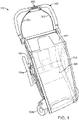
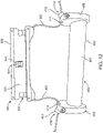
- FIG. 1 illustrates carrier which can be configured to carry, for example, a child, an elderly person, or a disabled person.
- carrier 100 can be a stroller for a child.
- Carrier 100 has one or more wheels 104, and preferably two or more wheels.
- Carrier 100 can have one, two, three, four, or more than four wheels.
- carrier 100 can have two rear wheels 104a and two front wheels 104b.
- the rear wheels 104a can be larger in diameter than the front wheels 104b.
- a rear wheel 104a can be disposed on each of a left and right side of carrier 100.
- carrier 100 can have one front wheel 104b disposed in the center of the front portion of carrier 100, for example, for use while jogging.
- Carrier 100 includes frame 102.
- Frame 102 can be made from any suitable material, for example, metal, plastic, or composite.
- Frame 102 can define compartment 106, within which a passenger, for example, a child, can sit while carrier 100 is in use.
- a cover 107 can be disposed on all or a portion of frame 102 to enclose compartment 106 completely or partially.
- One or more of the wheels 104 includes a brake or braking system 105.
- each of a left and right rear wheel 104 can have its own brake or braking system 105.
- a brake actuator 300 is disposed on or about handle bar 200 of carrier 100 for activating the braking system 105 at one or both of the wheels 104 (e.g., rear wheels 104a).
- One or more cable 302 can be coupled with brake actuator 300 and one or both of the braking systems 105 of rear wheels 104a or front wheels 104b.
- two cables 302 can be coupled with brake actuator 300, for example, one cable 302 for a wheel 104 on each side of carrier 100.
- operably is not meant to be limiting and is intended to include one or more string, wire, plurality of braided or woven wires (e.g. metal or nylon wires), cord, band, rope, or any other elongated member sufficient to connect, for example, the braking system 105 of first and second wheels 104 on opposite sides of carrier 100 through brake actuator 300 or to separately connect each braking system 105 with brake actuator 300.
- string wire, plurality of braided or woven wires (e.g. metal or nylon wires), cord, band, rope, or any other elongated member sufficient to connect, for example, the braking system 105 of first and second wheels 104 on opposite sides of carrier 100 through brake actuator 300 or to separately connect each braking system 105 with brake actuator 300.
- Brake actuator 300 can be activated by rotating brake actuator 300 about handle bar 200 of carrier 100. Rotation of brake actuator 300 can displace cable(s) 302 to activate the brakes or braking systems 105 at wheels 104. For example, rotating brake actuator 300 toward the user can pull cable 302, placing an upward force at the first and second ends of cable 302 attached with the braking systems 105 at the wheels 104. In some embodiments, activation of brake actuator 300 can activate both braking systems 105 simultaneously. Braking systems 105 can be band brakes, disc brakes, rim brakes, drum brakes, or any other braking system known in the art to apply, for example, a frictional braking force to wheels 104.
- the brake actuator 300 rotation can trigger an electric motor or hydraulic brake cylinders that increase braking power and reduce the input force at the brake actuator.
- a wireless option can be used, where rotating the brake actuator 300 activates braking systems 105 at the wheels 104 by sending a wireless signal to the braking systems 105.
- the braking actuators can be designed to enhance force output for certain types of braking systems, for example, by changing the angle of entry, amount of handle rotation, and/or distance of cable travel.
- band brakes and disc brakes are described.
- band brakes can be used in braking system 105.
- the force required to apply band brakes is greater than the force required to apply disc brakes to achieve the required braking power. Therefore, the entry angle ⁇ 3 (see FIG. 22 ) of the cable(s) 302 with respect to a side surface 407, 409 of the brake actuator 300 is typically larger for band brakes.
- the angle of entry may be between 40 and 80 degrees. In some embodiments, the angle of entry may be between 50 and 70 degrees. In some embodiments, the angle of entry may be between 55 and 65 degrees. In some embodiments, the angle of entry may be about 60 degrees. Other ranges within those disclosed are also contemplated and the endpoints are not meant to be limiting.
- the angle of entry ⁇ 3 can be shallower in comparison to band brakes. This can reduce friction applied onto the cable(s), for example, from an interior surface of the nipples of the brake actuator.
- the angle of entry may be between 5 and 30 degrees. In some embodiments, the angle of entry may be between 10 and 25 degrees. In some embodiments, the angle of entry may be between 12 and 20 degrees. In some embodiments, the angle of entry may be about 15 degrees. Other ranges within those disclosed are also contemplated and the endpoints are not meant to be limiting.
- Brake actuator rotation and cable travel can also be adjusted according to brake type and force requirements. These are related in that increasing the rotation of the brake actuator also increases the cable travel because the cable(s) wrap farther around the handle bar. Also, if the inner diameter of the handle bar is increased, generally the cable travel distance should be increased to apply the required amount of force to operate the brakes. Further, the cable travel can be increased by moving the cable termination ends outward axially from the center of the handle. That is, the closer the termination point is to the end of the housing, the more the cable can wrap around the handle bar, thereby increasing the cable travel.
- the brake actuator rotation may be between 30 and 115 degrees around the handle bar. In some embodiments, the brake actuator rotation may be between 60 and 85 degrees. In some embodiments, the brake actuator rotation may be between 65 and 80 degrees. In some embodiments, the brake actuator rotation may be between 70 and 75 degrees. In some embodiments, the brake actuator rotation for band brake systems may be about 70 degrees. In some embodiments, the brake actuator rotation for disc brake systems may be about 75 degrees.
- the cable travel may be between 5 and 50 mm. In some embodiments, the cable travel may be between 15 and 30 mm. In some embodiments, the cable travel for band brake systems may be between 17 and 21 mm. In some embodiments, the cable travel for band brake systems may be about 19 mm. In some embodiments, the cable travel for disc brake systems may be between 23 and 27 mm. In some embodiments, the cable travel for disc brake systems may be about 25 mm. Other ranges for brake actuator rotation and cable travel within those disclosed are also contemplated and the endpoints are not meant to be limiting.
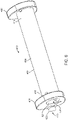
- FIG. 2 illustrates brake actuator 300 and handle bar 200, according to an embodiment.
- brake actuator 300 can be disposed about handle bar 200.
- Rotating brake actuator 300 about handle bar 200 can activate the braking systems 105 at wheels 104.
- rotating brake actuator 300 in the direction shown by the arrow R in FIG. 2 can activate the braking systems 105.
- the direction of the arrow R in FIG. 2 represents rotating brake actuator 300 toward the user of carrier 100 (i.e., rearward) where the user is pushing carrier 100, for example, when being used as a stroller.
- the view shown in FIG. 2 represents a front perspective view of brake actuator 300. Views from the direction that the user faces while pushing carrier 100 are referred to as rear or rear perspective views. Therefore, for example, a rear perspective view is from the perspective of a user while pushing carrier 100 in a conventional forward direction of travel while holding onto handle bar 200.
- Brake actuator 300 includes a base member 400 and housing 500.
- Cable(s) 302 can be coupled with brake actuator 300.
- a single cable 302 can be disposed through housing 500.
- a first end of cable 302 can be coupled with a first braking system 105 of a wheel 104, for example, a rear wheel on the right side of carrier 100 as viewed from the user's perspective.
- cable 302 can run through brake actuator 300, for example, through housing 500, and also connect to a second braking system 105 at a second wheel 104, for example, a rear wheel on the left side of carrier 100 as viewed from the user's perspective.
- two cables 302 can be coupled with brake actuator 300, for example, to an interior of housing 500.
- the first cable 302 connects to a first braking system 105 and the second cable connects to a second braking system 105.
- the user in order to activate one or both of the braking systems 105, the user can rotate brake actuator 300 toward the user (i.e., in the rearward direction), as shown for example in FIG. 2 .
- the user can rotate the brake actuator 300 forward in order to activate the braking system(s) 105.
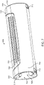
- FIGS. 3 and 4 illustrate a rear perspective view and a front perspective view, respectively, of a brake actuator 300 and handle bar 200, according to an embodiment.
- handle bar 200 can include a bar 202 about which brake actuator 300 can be disposed.
- Bar 202 can be made of any suitable material, for example, metal, plastic, or composite.
- bar 202 can be cylindrical.
- bar 202 can have a hollow interior.
- Bar 202 can have a central axis disposed in a lengthwise direction. In some embodiments, the central axis can be an axis of rotation for brake actuator 300.
- one or more pad 204 can be disposed about bar 202. Pads 204 can be disposed about all or a portion of bar 202. In some embodiments, pads 204 can be foam or another material to provide a softer gripping surface for the user to hold while pushing carrier 100.
- Brake actuator 300 can include base member 400, as shown for example in FIGS. 5 and 6 .
- Base member 400 can be made of any suitable material, for example, metal, plastic, or composite.
- base member 400 can be disposed about bar 202.
- base member 400 can include a through-hole 420 through which bar 202 can extend.
- through-hole 420 can include inner surface 421, which can be disposed against an outer surface 203 of bar 202.
- through-hole 420 can have a size and shape that conforms to an outer surface of bar 202 such that through-hole 420 is coaxial with bar 202.
- base member 400 can have a first portion 432 coupled to a second portion 434 around bar 202.
- Base member 400 includes main body 404 having an outer surface 402.
- main body 404 can be cylindrical and through-hole 420 can extend therethrough, forming a tubular elongate member.
- Base member 400 has a first collar 406 disposed at a first end 416 of main body 404.
- base member 400 can have a second collar 408 disposed at a second end 418 of main body 404.
- First collar 406 and second collar 408 can have a shape and size that is larger than through-hole 420 of main body 404.
- the collars 406, 408 can be any suitable shape, for example, circular, oval, oblong, elliptical, or any other shape.
- first and second collars 406, 408 may not be symmetrically disposed about through-hole 420.
- first and second collars 406, 408 may extend further in the forward direction away from the central axis of bar 202.
- first collar 406 and second collar 408 can have a passage 410 extending therethrough.
- passage 410 can have an outer opening 412 disposed on an exterior side of the collar and an inner opening 414 on an interior side of the collar.
- outer opening 412 can be larger than inner opening 414.
- outer opening 412 and/or inner opening 414 can be circular.
- passage 410 can include a protrusion (e.g., a nipple) 422 extending from the surface of collars 406, 408.
- protrusion 422 can extend from an exterior surface of collars 406, 408 and define outer opening 412 of passage 410.
- cable 302 can extend through passage 410 of both first collar 406 and second collar 408.
- cable 302 can extend through outer opening 412 of passage 410 on first collar 406, through first collar 406, and out of inner opening 414 of first collar 406.
- cable 302 can extend across a length of the main body 404 of base member 400, with or without contacting main body 404, into the inner opening 414 of second collar 408, and exit the outer opening 412 of passage 410 of second collar 408.
- base member 400 can include one or more screw holes 424 located in the surface of base member 400, for example, in first collar 406, second collar 408, and/or main body 404. Screw holes 424 can be configured to receive a screw or another fastener so that base member 400 can be coupled with housing 500.
- brake actuator 300 includes housing 500.
- Housing 500 can be made from any suitable material, for example, plastic, metal, or composite. Housing 500 is disposed about base member 400. In some embodiments, housing 500 can be coupled with base member 400, for example, by screws or other fasteners which can extend through screw holes 514, for example, as shown in FIG. 8 . Base member 400 and housing 500 can be coupled by other mechanisms, for example, friction fit, snap fit, etc. Housing 500 can rotate around base member 400.
- Housing 500 can include outer surface 502. In some embodiments, outer surface 502 can include one or more gripping portions 504. In some embodiments, outer surface 502 can include two gripping portions 504. In some embodiments, gripping portion 504 can include one or more ridge 506 protruding from outer surface 502 of housing 500. In some embodiments, gripping portion 504 can include two, three, four or more ridges 506. The gripping portion 504 can facilitate gripping of housing 500 by the user, for example, in order to rotate brake actuator 300. Housing 500 includes a first portion 508 and a second portion 510. In some embodiments, each of first portion 508 and second portion 510 of housing 500 can include a gripping portion 504.
- first portion 508 can face away from the user (i.e., the front portion), as shown in FIG. 8 .
- second portion 510 can face the user (i.e., the rear portion), as shown in FIG. 7 .
- housing 500 can include one or more screw hole 512 through which a screw or other fastener can couple first portion 508 and second portion 510.
- First portion 508 and second portion 510 of housing 500 can be coupled by other mechanisms, for example, friction fit, snap fit, etc.
- housing 500 can be a single integral member.
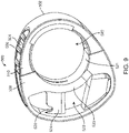
- Housing 500 can include a through-hole 520, which can have an inner surface 521.
- inner surface 521 of through hole 520 can be formed from both the first portion 508 and the second portion 510 of housing 500, as shown for example in FIG. 9 .
- inner surface 521 of through-hole 520 can have a size and shape configured to be disposed about outer surface 402 of the main body 404 of base member 400.
- through-hole 520 can be coaxial with through-hole 420 of base member 400 and/or bar 202 of handle bar 200.
- through-hole 520 can be cylindrical.
- housing 500 can include one or more cavity 522 extending through housing 500.
- cavity 522 can extend entirely through housing 500 from a first end 516 to a second end 518.
- a wall 523 can at least partially separate cavity 522 and through-hole 520 within housing 500. This can separate cavity 522 from the main body 404 of base member 400 extending through the through-hole 520 of housing 500.
- a ledge 524 can be disposed within cavity 522.
- ledge 524 can be a piece of material extending from wall 523 to first portion 508 of housing 500.
- cable 302 can extend through cavity 522 and across ledge 524, for example, across an upper surface of ledge 524.
- the ledge 524 can help displace the cable 302 to activate the braking system 105 at wheels 104.
- ledge 524 can include one or more notch 526.
- cable 302 can be disposed within notch 526, for example, as shown in FIG. 10 . This can facilitate retention of cable 302 across or within ledge 524.
- ledge 524 can have a hole (not shown) therethrough, through which the cable 302 can extend.
- FIG. 10 illustrates a partial interior view of brake actuator 300 as viewed from second end 418 of base member 400 and second end 518 of housing 500 (i.e., the right side of carrier 100 as viewed from the user's perspective while pushing carrier 100).
- Center point C can be the lengthwise center axis of bar 202, which can also be the axis of rotation for brake actuator 300.
- cable 302 can enter passage 410 of base member 400, extend into cavity 522 of housing 500, and across ledge 524 of housing 500, for example within notch 526. As shown, for example, in FIG.
- an upper surface of ledge 524 can be disposed above passage 410 thereby creating a "pre-load” angle ⁇ 1 for cable 302 when it is disposed through housing 500 in a starting or “at rest” position for brake actuator 300, where brake actuator 300 is not rotated.
- the pre-load angle ⁇ 1 can be defined as an angle between an axis A through a center of passage 410 and axis B1 through a center of cable 302 where it passes across ledge 524, as shown for example in FIG. 10 .
- ⁇ 1 can be greater than 10 degrees.
- ⁇ 1 can be between 5 and 30 degrees.
- ⁇ 1 can be between 10 and 25 degrees.
- ⁇ 1 can be between 15 and 20 degrees.
- ⁇ 1 can be between 17 and 19 degrees.
- ⁇ 1 can be about 18 degrees. This can provide brake actuator 300 with some pre-loaded force to facilitate activation of the brakes 105.
- cable 302 disposed across ledge 524 can be displaced and angle ⁇ 2 in the direction of the arrow R shown in FIG. 10 .
- cable 302 can end up being disposed with axis B2 extending through the center of cable 302 along ledge 524.
- the displacement from axis B1 to axis B2 i.e., ⁇ 2
- ⁇ 2 can be between 30 and 60 degrees.
- ⁇ 2 can be between 35 and 55 degrees.
- ⁇ 2 can be between 40 and 50 degrees.
- ⁇ 2 can be between 44 and 46 degrees.
- ⁇ 2 can be about 45 degrees.
- cable 302 can be located a distance d 1 from a center point C of a central axis of bar 202.
- d 1 can be between 20 mm and 30 mm.
- d 1 can be between 22 mm and 28 mm.
- d 1 can be between 24 mm and 26 mm.
- d 1 can be about 25 mm. This can provide the proper angle to apply force along cable 302 to the brakes 105.
- FIG. 11 illustrates a partial front view of brake actuator 300, according to an embodiment.
- FIG. 11 shows a pathway of cable 302 through brake actuator 300, according to an embodiment.
- Cable 302 can enter outer opening 412 of passage 410, for example, via protrusion 422, pass through second collar 408, and exit inner opening 414. Cable 302 can then enter cavity 522 of housing 500 and pass across ledge 524. Cable 302 can then enter inner opening 414 of passage 410 in first collar 406 and exit outer opening 412 via protrusion 422 of first collar 406.
- cable 302 can include a crimped portion 304.
- crimped portion 304 can be a piece of material crimped onto cable 302 to provide a larger area.
- crimped portion 304 can be disposed in notch 526 of ledge 524 to help stabilize cable 302 within housing 500.
- crimped portion 304 can be disposed within a hole or window 525 of housing 500 to reduce lateral movement of cable 302 within housing 500.
- screw 306 or other fastening device can be used to couple first portion 508 of housing 500 with second portion 510 of housing 500.
- FIG. 12 illustrates a partial exploded view of brake actuator 300, according to an embodiment.
- cable 302 can extend through passage 410 of first collar 406 into cavity 522 of housing 500 and then through passage 410 of second collar 408.
- first portion 508 of housing 500 can have a wall 523 configured with a contour to fit about main body 404 of base member 400.
- first portion 508 can have cavity 522 through which cable 302 extends.
- a crimped portion 304 can be added to cable 302 through a window 525 of cavity 522 so that lateral movement of cable 302 is reduced within housing 500.
- crimped portion 304 can be used instead of, or in addition to, ledge 524 of housing 500.
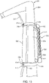
- FIG. 13 illustrates brake actuator 300 being assembled to handle bar 200, according to an embodiment.
- first portion 508 of housing 500 can be coupled with base member 400 and second portion 510 of housing 500 can be coupled with first portion 508 of housing 500 and base member 400.
- Inner surface 521 of first portion 508 and second portion 510 of housing 500 can be configured to fit tightly about outer surface 402 of main body 404 of base member 400.
- housing 500 can have a friction fit about base member 400.
- brake actuator 300 can be disposed in the center of handle bar 200. In some embodiments, brake actuator 300 can be disposed closer to one end or another of handle bar 200.
- FIGS. 14 and 15 illustrate brake actuator 300, according to an embodiment.
- cable 302 can be disposed exterior to housing 500.
- cable 302 can extend through passage 410 of first collar 406 of base member 400, for example through an outer opening 412 and an inner opening 414 of protrusion 422.
- cable 302 can extend under a paddle 530 of housing 500 and then through passage 410 of second collar 408, for example, through an inner opening 414 and then through an outer opening 412 of protrusion 422.
- cable 302 can engage one or more flange 532 extending from paddle 530.
- brake actuator 300 when brake actuator 300 is rotated by the user, for example, toward the user, cable 302 can be displaced by paddle 530, thereby activating the braking systems 105 at wheels 104.
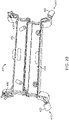
- FIG. 16 illustrates a partial exploded view of brake actuator 300, according to an embodiment.
- FIG. 18 illustrates the embodiment of FIG. 16 attached to handle bar 200.
- brake actuator 300 can include base member 400 having a main body 404 and first and second collars 406, 408 with passages 410 for cables 302.
- housing 500 can have a first portion 508, a second portion 510, and an outer surface 502 with one or more gripping portions 504 with ridges 506.
- first and second cables 302 can be coupled to brake actuator 300.
- first ends of the cables 302 can be connected to respective braking systems 105, as shown for example in FIG. 1 .
- second ends of the cables 302 can be coupled to housing 500, for example, first portion 508 of housing 500 or second portion 510 of housing 500.
- the second ends of the cables 302 can be coupled to housing 500 by cable couplings 310.
- cable couplings 310 can be plastic or metal components used to fixedly couple the second ends of the cables 302 to housing 500, for example, with a screw 312.
- cables 302 can have a bearing 301 disposed at or near the end of the cable 302, which can be retained by cable coupling 310 to couple the cable 302 with housing 500.
- Bearing 301 can be, for example, a spherical or cylindrical component at the end of cable 302.
- a first cable 302 can extend through passage 410 of first collar 406, for example through nipple 422, and into an interior cavity 542 defined by housing 500.
- a second cable 302 can extend through passage 410 of second collar 408 and into interior cavity 542 of housing 500.
- first portion 508 of housing 500 can have an interior surface with one or more ribs 546 extending therefrom.
- ribs 546 can be curved to contact and correspond with the outer surface 402 of main body 404 of base member 400.
- base member 400 can have a first portion 432 and a second portion 434, which can be coupled together, for example, by screws 436, snap-fit, friction fit, adhesive, or other attachment means.
- base member 400 can include one or more bearing surface 430 to facilitate rotation of housing 500 around base member 400.
- Bearing surface 430 can be, for example, a raised ring around main body 404 of base member 400.
- main body 404 can include a bearing surface 430 at first end 416 and/or at second end 418.
- FIG. 17 illustrates a first portion 508 of housing 500, according to an embodiment.
- the attachment locations for cable couplings 310 to couple cables 302 with housing 500 are disposed at first end 516 and second end 518 of the housing 500.
- the attachment locations for cable couplings 310 shown in FIG. 16 can be used with a band brake system and the attachment locations for cable couplings 310 shown in FIG. 17 can be used with a disc brake system. Attaching cable couplings 310 closer to the center of the housing 500, as shown in FIG. 16 , can increase the force applied upon rotating the brake actuator 300. As discussed above, band brakes generally require more force to operate than disc brakes. So in some embodiments, attachment locations for cable couplings 310 closer to ends 516, 518 of housing 500, as shown in FIG. 17 , can be used with a disc brake system because it requires less force to operate the brakes.
- FIG. 18 illustrates brake actuator 300 disposed on a handle bar 200, according to an embodiment.
- base member 400 can include a through-hole 420 for handle bar 200, a main body 404 having an outer surface 402, a first collar 406 disposed at a first end 416 of main body 404, and a second collar 408 disposed at a second end 418 of main body 404.
- first collar 406 and second collar 408 can have a passage 410 extending therethrough, with an outer opening 412 disposed on an exterior side of the collar and an inner opening 414 on an interior side of the collar.
- passage 410 can include a protrusion (e.g., a nipple) 422 extending from the surface of collars 406, 408.
- a first cable 302 can extend through passage 410 of first collar 406 and a second cable 302 can extend through passage 410 of second collar 408, with both cables 302 fixedly attaching to an interior of housing 500.
- the position and orientation of nipples 422 can dictate the entry angle ⁇ 3 of cable(s) 302, as discussed herein with reference to FIG. 22 .
- FIG. 19 illustrates stopper 440 on base member 400, according to an embodiment.
- Stopper 440 can limit the rotation of brake actuator 300 by acting as an interference surface.
- stopper 440 can include a top surface 442 and a front surface 444, each extending from the outer surface 402 of main body 404 of base member 400.
- the top surface 4442 and front surface 444 can meet, forming a wedge shape.
- the stopper 440 can engage one or more of the ribs 546 on the housing 500 to limit the rotational movement of the housing 500 around the base member 400.
- FIG. 20 illustrates an interior view of base member 400, according to an embodiment.
- base member 400 can have a first portion 432 and a second portion 434 that are coupled together to form base member 400.
- FIG. 20 illustrates bearing pins 450, which in some embodiments can be disposed in passage 410.
- Bearing pins 450 can be, for example, metal or plastic pins that can rotate to reduce friction on cable(s) 302 as the cable moves upon rotating the brake actuator 300. For example, when rotating brake actuator 300 to actuate the braking systems 105, cable(s) 302 travel a distance to wrap around and along base member 400.
- the bearing pins 450 reduce the friction imparted onto the cable(s) 302, for example, by the interior surface of the nipples 422.
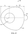
- FIG. 21 illustrates a side view of a brake actuator 300, according to an embodiment.
- the side view shows side surface 409 of second collar 408 of base member 400, with through-hole 420 extending through base member 400.
- Through-hole 420 can have a central axis C.
- FIG. 21 illustrates a non-circular shape of brake actuator 300 about central axis C, according to some embodiments of brake actuator 300.
- this non-circular shape can result from the collars 406, 408 having an oblong shape such that a first portion (for example near PI) has a smaller radius of curvature than a second portion (for example near P2).
- the non-circular shape creates an ergonomically designed brake actuator that provides a better grip to user and also provides space for the cables within the housing 500 of the brake actuator 300. The wider section allows the cable to remain internal and protects the user's hands from an external cable.
- a first radius R1 from the central axis C to a first point PI on an outer surface of the rotatable brake actuator 300 is smaller than a second radius R2 from the central axis C to a second point P2 on the outer surface of the rotatable brake actuator 300.
- the first radius R1 and the second radius R2 can be collinear.
- PI can define the rearmost point of brake actuator 300 and P2 can define the forward-most point of brake actuator 300.
- the first point PI is configured to be gripped by a palm of a user and the second point P2 is configured to be gripped by one or more fingers of the user.
- This design provides the user with a comfortable handle at the palm location, while also providing a finger grip area for the tips of the fingers.
- ridges 506 on gripping portions 504, for example, made of a rubber material also adds to the ergonomics and feel of the brake actuator 300.
- FIG. 22 illustrates a schematic of brake actuator 300, according to an embodiment, which depicts the entry angle ⁇ 3 of the cables 302 relative to the brake actuator 300.
- the cables 302 can extend into the brake actuator 300, for example through passages 410 and/or nipples 422.
- FIG. 22 illustrates entry angle ⁇ 3 formed between a plane at side surface 407 of first collar 406 and a plane through a lengthwise direction of cable 302.
- the entry angle ⁇ 3 may be between 5 and 80 degrees depending on the type of braking system and required force output to operate the braking system.
- FIG. 23 illustrates a force schematic of a conventional cabled brake system
- FIG. 24 illustrates a force schematic of a brake system as described herein, according to an embodiment.
- conventional cabled brake systems impart a linear tension force T in the x-direction of the cable(s), which pulls the cable at brakes 105 in the same direction as the linear tension force T.
- the cable is pulled in only one direction and so there is only one force component, which is along the axis of the cable.
- FIG. 24 where the tension force T is applied in a y-direction perpendicular to the direction of the cable(s), imparting a tension force T L to a left brake 105 and a tension force T R to a right brake.
- the angled deflection of the cables increases the tension in the cable, thus requiring less force to be exerted by the user to achieve the same travel distance of the cables and the same braking force at the wheel(s) as the conventional system.
- a method of activating a braking system of a child transport carrier can include rotating the braking actuator about the handle bar of the carrier.
- rotating the braking actuator can displace a cable that is disposed through braking actuator, for example, through the first passage of the first collar, the cavity. This rotation can cause the cable to move from a first position to a second position, thereby imparting force along the cable to activate a first and second brake of respective first and second wheels disposed on opposite sides of the carrier.
- the method can include rotating the braking actuator toward the user.
- the method can include rotating the braking actuator with one hand by the user.
- the method can include rotating the braking actuator more than 20 degrees. In some embodiments the method can include rotating the braking actuator more than 30 degrees. In some embodiments the method can include rotating the braking actuator more than 40 degrees. In some embodiments the method can include rotating the braking actuator about 45 degrees.
- a method of activating a braking system of a child transport carrier can include rotating the braking actuator about the handle bar of the carrier.
- a housing of the braking actuator can rotate about a base member of the braking actuator.
- rotating the braking actuator can displace one or more cables coupled to the braking actuator.
- two cables can be coupled the braking actuator, for example, within a housing of the braking actuator. This rotation can cause the cables to travel around and along the handle bar, thereby imparting force along the cables, which in some embodiments activate a first and second brake of respective first and second wheels disposed on opposite sides of the carrier.
- the method can include rotating the braking actuator toward the user.
- the method can include rotating the braking actuator with one hand by the user. In some embodiments the method can include rotating the braking actuator more than 20 degrees. In some embodiments the method can include rotating the braking actuator more than 60 degrees. In some embodiments the method can include imparting a cable travel distance of more than 15 mm.
Landscapes
- Engineering & Computer Science (AREA)
- Transportation (AREA)
- Mechanical Engineering (AREA)
- Chemical & Material Sciences (AREA)
- Combustion & Propulsion (AREA)
- Health & Medical Sciences (AREA)
- Public Health (AREA)
- Braking Arrangements (AREA)
- Handcart (AREA)
- Carriages For Children, Sleds, And Other Hand-Operated Vehicles (AREA)
- Transmission Of Braking Force In Braking Systems (AREA)
- Mechanical Control Devices (AREA)
Description
- The present invention relates to passenger transport carriers. More specifically, embodiments of the present invention relate to rotating handles for brakes of passenger transport carriers, such as strollers.
- Passenger transport carriers carry a passenger, for example, a child, from one place to another. The transport carrier can have wheels with a braking system that can be operated by the user. The braking system can stop or slow the travelling motion of the carrier.
-
CH262695 -
US6123343 shows a shopping cart with a brake system. By a rotating brake actuator placed on the handle bar the brake can be inactivated allowing movement of the shopping car. -
GB2219054 - Solving the drawbacks of the prior art is achieved according to the invention by a child transport carrier according to the features of claim 1. Preferred embodiments are defined in the dependent claims.
- A passenger transport carrier, for example, a child transport carrier, can include a handle bar and a rotatable brake actuator disposed about a lengthwise axis of the handle bar. One or more cables are coupled to the rotatable brake actuator. The cable(s) have a first end and a second end. In some embodiments, a first wheel brake can be coupled to the first end of the cable and a second wheel brake can be coupled to the second end of the cable. In some embodiments, a first end of the cable can be coupled to the first wheel brake and the second of the cable can be coupled to the rotatable brake actuator. In some embodiments, rotating the rotatable brake actuator about the lengthwise axis of the handle bar can activate the first wheel brake and the second wheel brake. In some embodiments, rotating the rotatable brake actuator about the lengthwise axis of the handle bar can simultaneously activate the first wheel brake and the second wheel brake.
- In some embodiments, the rotatable brake actuator can be disposed at a midpoint of the handle bar. In some embodiments, the rotatable brake actuator can be configured to rotate in a direction toward a user positioned longitudinally rearward of the handle bar. In some embodiments, the rotatable brake actuator can be configured to rotate in a direction away from a user positioned longitudinally rearward of the handle bar. The cable can be disposed through a housing of the rotatable brake actuator. The cable can be coupled to an interior surface of the housing.
- In some embodiments, a child transport carrier can include a frame, a first wheel coupled to the frame having a first brake, a second wheel coupled to the frame having a second brake, and a handle bar coupled to the frame. A rotatable brake actuator can be disposed about the handle bar. In some embodiments, the brake actuator can include a base member having an elongate tubular body disposed coaxially about the handle bar. In some embodiments, the base member can include a first collar disposed at a first end of the body and having a first passage therethrough, and a second collar disposed at a second end of the body and having a second passage therethrough. In some embodiments, a housing can be disposed about the body of the base member and the brake actuator can include a cavity extending through the housing from a first end of the housing to a second end of the housing. In some embodiments, the carrier can include a cable extending from the first brake to the second brake and passing through the first passage of the first collar, the cavity of the housing, and the second passage of the second collar. In some embodiments, rotating the brake actuator can displace the cable, thereby actuating the first and second brakes.
- In some embodiments, a ledge can be disposed within the cavity of the housing. In some embodiments, the cable can extend over an upper surface of the ledge. In some embodiments, the upper surface of the ledge can include a notch. In some embodiments, the cable can be disposed in the notch. In some embodiments, the cable can be disposed through a hole in the ledge.
- In some embodiments, the first collar can include a first protrusion (e.g., a nipple) extending from the first collar. The first protrusion can define an outer opening of the first passage. In some embodiments, the second collar can include a second protrusion extending from the second collar. The second protrusion (e.g., a nipple) can define an outer opening of the second passage. In some embodiments, each of the first collar and second collar can have an inner opening facing the body of the base member.
- In some embodiments, the housing can include at least one gripping area on an outer surface of the housing. In some embodiments, the gripping area can have at least one ridge extending from the outer surface. In some embodiments, the gripping area can have two, three, or more than three ridges.
- In some embodiments, the housing can include a through-hole having an inner surface configured to be disposed about an outer surface of the body of the base member. In some embodiments, the inner surface of the through-hole can contact the outer surface of the body of the base member around an entirety of the body. In some embodiments, the housing can include a wall disposed between the through-hole and the cavity.
- In some embodiments, a rotatable braking actuator for a child transport carrier can include a base member having an elongate tubular body with a longitudinal axis of rotation, a first collar disposed at a first end of the body and having a first passage therethrough, and a second collar disposed at a second end of the body and having a second passage therethrough. In some embodiments, a housing can be disposed about the body of the base member and coupled to the base member. In some embodiments, the housing can include a cavity extending through the housing from a first end of the housing to a second end of the housing. In some embodiments, a cable can extend through the first passage of the first collar, the cavity of the housing, and the second passage of the second collar.
- In some embodiments, the housing and the base member can be configured to simultaneously rotate about the longitudinal axis of rotation. In some embodiments, the housing can rotate about the longitudinal axis of rotation and the base member can remain fixed in place. In some embodiments, the first and second passage can each have an interior opening facing the body of the base member. In some embodiments, a distance between the interior openings can be between 85 mm and 225 mm. In some embodiments, the distance between the interior openings can be between 110 mm and 150 mm. In some embodiments, the distance between the interior openings can be between 120 mm and 140 mm. In some embodiments, the distance between the interior openings can be between 125 mm and 135 mm. In some embodiments, the distance between the interior openings can be about 130 mm.
- In some embodiments, a perpendicular distance from the longitudinal axis of rotation to the cable(s) within the cavity can be between 10 mm and 50 mm. In some embodiments, the perpendicular distance from the longitudinal axis of rotation to the cable within the cavity can be between 20 mm and 30 mm. In some embodiments, the perpendicular distance from the longitudinal axis of rotation to the cable can be between 22 mm and 28 mm. In some embodiments, the perpendicular distance from the longitudinal axis of rotation to the cable(s) can be between 24 mm and 26 mm. In some embodiments, the perpendicular distance from the longitudinal axis of rotation to the cable(s) can be about 25 mm.
- In some embodiments, a ledge having a notch can be disposed within the cavity of the housing. In some embodiments, the cable can be disposed in the notch.
- In some embodiments, a first axis can extending through the longitudinal axis of rotation and the first passage and a second axis extend through the longitudinal axis of rotation and the notch. In some embodiments, an angle between the first axis and the second axis can be between 5 and 30 degrees when the braking device is in a starting position (i.e., not rotated). In some embodiments, the angle between the first axis and the second axis can be between 10 and 25 degrees when the braking device is in the starting position. In some embodiments, the angle between the first axis and the second axis can be between 15 and 20 degrees when the braking device is in the starting position. In some embodiments, the angle between the first axis and the second axis can be between 17 and 19 degrees when the braking device is in the starting position. In some embodiments, the angle between the first axis and the second axis can be about 18 degrees when the braking device is in the starting position.
- In some embodiments, the base member and/or the housing can be configured to rotate between 25 and 125 degrees from the starting position to an ending position. In some embodiments, the base member and/or the housing can be configured to rotate between 30 and 60 degrees from the starting position to an ending position. In some embodiments, the base member and/or the housing can be configured to rotate between 35 and 55 degrees from the starting position to the ending position. In some embodiments, the base member and/or the housing can be configured to rotate between 40 and 50 degrees from the starting position to the ending position. In some embodiments, the base member and/or the housing can be configured to rotate between 44 and 46 degrees from the starting position to the ending position. In some embodiments, the base member and/or the housing can be configured to rotate about 45 degrees from the starting position to the ending position.
- In some embodiments, a method of activating a braking system of a child transport carrier can include rotating a braking actuator about a handle bar of the carrier. In some embodiments, the braking actuator can include a base member having an elongate tubular body disposed around the handle bar, a first collar disposed at a first end of the body and having a first passage therethrough, and a second collar disposed at a second end of the body and having a second passage therethrough. In some embodiments, the braking actuator can include a housing disposed about and coupled to the base member. In some embodiments, the housing can have a cavity extending through the housing from a first end of the housing to a second end of the housing. In some embodiments, rotating the braking actuator can displace a cable disposed through the first passage, the cavity, and the second passage from a first position to a second position, thereby imparting force along the cable to activate a first and second brake of respective first and second wheels disposed on opposite sides of the carrier. In some embodiments, rotating the braking actuator can displace a cable disposed through the first passage and coupled to the housing, thereby imparting force along the cable to activate a first brake of a first wheel of the carrier. In some embodiments, rotating the braking actuator can displace a first and second cable coupled to the housing and to respective first and second brakes, thereby imparting force along the cables to activate the first and second brake of respective first and second wheels.
- A child transport carrier includes a handle bar and a rotatable brake actuator disposed along a lengthwise axis of the handle bar. A first cable is coupled to the rotatable brake actuator. The first cable has a first end and a second end. A first wheel brake of a first wheel is coupled to the first end of the first cable. Rotating the rotatable brake actuator around the lengthwise axis of the handle bar activates the first wheel brake.
- In some embodiments, rotating the rotatable brake actuator can wrap the first cable in both circumferential and lengthwise directions. In some embodiments, the first cable can wrap around an outer surface of a base member disposed inside a housing of the rotatable brake actuator. In some embodiments, rotating the rotatable brake actuator can impart a force perpendicular to a lengthwise direction of the first cable.
- The second end of the first cable is coupled to an interior of a housing of the rotatable brake actuator. The second end of the first cable is fixedly attached to the interior of the housing of the rotatable brake actuator.
- In some embodiments, the carrier can include a second cable having a first end and a second end. A second wheel brake of a second wheel can be coupled to the first end of the second cable. Rotating the rotatable brake actuator around the lengthwise axis of the handle bar can activate the second wheel brake. In some embodiments, rotating the rotatable brake actuator around the lengthwise axis of the handle bar can simultaneously activate the first wheel brake and the second wheel brake. In some embodiments, increasing the rotation of the rotatable brake actuator around the handle bar can increase a braking force applied to the first and/ or second wheel brake.
- The rotatable brake actuator includes a base member having a main body disposed around the handle bar. A first collar is disposed at a first end of the main body having a first passage through the first collar. A housing is disposed around the main body of the base member defining an interior cavity. The first cable is disposed through the first passage of the first collar and coupled to the housing within the interior cavity. In some embodiments, the first cable can enter the first passage at an angle between 10 and 70 degrees relative to an exterior surface of the first collar. In some embodiments, the first cable can enter the first passage at an angle of about 15 degrees relative to the exterior surface of the first collar. In some embodiments, the first cable can enter the first passage at an angle of about 60 degrees relative to the exterior surface of the first collar.
- A child transport carrier includes a handle bar and a brake actuator configured to couple to the handle bar and rotate around the handle bar. The brake actuator includes a housing having a first portion and a second portion configured to couple to the first portion around the handle bar. In some embodiments, the first portion and the second portion of the housing can be coupled by screws or snap-fit. A first cable having a first end is coupled to a first wheel brake and a second end is coupled to the housing. Rotating the brake actuator around the handle bar activates the first wheel brake. In some embodiments, the second end of the first cable can be fixedly attached to an interior surface of the first portion of the housing.
- In some embodiments, the carrier can include a second cable having a first end coupled to a second wheel brake and a second end coupled to the housing of the brake actuator. In some embodiments, rotating the brake actuator around the handle bar can activate the second wheel brake.
- The brake actuator includes a base member having a main body disposed around the handle bar. In some embodiments, the main body of the base member can be cylindrical. A housing is disposed around the main body of the base member, defining an interior cavity. The base member of the brake actuator includes a first collar disposed at a first end of the main body. In some embodiments, the first collar can have a first nipple extending from the first collar and defining a first passage through the first collar. The first cable can be disposed through the first passage. In some embodiments, a second collar can be disposed at a second end of the main body. In some embodiments, the second collar can have a second nipple extending from the second collar and defining a second passage through the second collar. In some embodiments, a second cable can be disposed through the second passage.
- In some embodiments, an interior surface of the housing can include a plurality of curved ribs extending from the interior surface. In some embodiments, the ribs can be configured to contact an outer surface of the main body of the base member. In some embodiments, the housing can be configured to rotate around the base member. In some embodiments, the base member can include a stop member extending from an outer surface of the main body. In some embodiments, the stop member can be configured to engage at least one of the plurality of ribs, thereby limiting rotation of the brake actuator around the handle bar.
- A child transport carrier includes a handle bar having a central axis and a rotatable brake actuator disposed around the handle bar. In some embodiments, a first radius from the central axis to a first point on an outer surface of the rotatable brake actuator can be smaller than a second radius from the central axis to a second point on the outer surface of the rotatable brake actuator. In some embodiments, the first radius and the second radius can be collinear. A first cable having a first end is coupled to a first wheel brake and a second end is coupled to the rotatable brake actuator. Rotating the rotatable brake actuator around the handle bar activates the first wheel brake.
- In some embodiments, the rotatable brake actuator can include a base member having a cylindrical main body disposed symmetrically around the central axis of the handle bar and a housing disposed around the main body. In some embodiments, a first collar can be disposed at a first end of the main body and having a first passage therethrough, and a second collar can be disposed at a second end of the main body and having a second passage therethrough. In some embodiments, the first collar and the second collar can have an oblong shape such that a first portion of the first and second collars has a smaller radius of curvature than a second portion of the first and second collars.
- In some embodiments, the rotatable brake actuator can include at least one gripping area. In some embodiments, the gripping area can include at least one ridge extending from an outer surface of the rotatable brake actuator. In some embodiments, the first point of the rotatable brake actuator can be configured to be gripped by a palm of a user and the second point of the rotatable brake actuator can be configured to be gripped by one or more fingers of the user.
- In some embodiments, the carrier can include a second cable having a first end coupled to a second wheel brake and a second end coupled to the rotatable brake actuator. In some embodiments, the second ends of the first and second cables can be fixedly attached to an interior of a housing of the rotatable brake actuator.
- The accompanying drawings, which are incorporated herein and form a part of the specification, illustrate the embodiments of the invention and, together with the description, further serve to explain the principles and to enable a person skilled in the relevant art(s) to make and use the embodiments.
-
FIG. 1 illustrates a front perspective view of a passenger transport carrier, according to an embodiment. -
FIG. 2 illustrates a brake actuator, according to an embodiment. -
FIG. 3 illustrates a rear perspective view of a brake actuator, according to an embodiment. -
FIG. 4 illustrates a front perspective view of a brake actuator, according to an embodiment. -
FIG. 5 illustrates a front perspective view of a base member of a brake actuator, according to an embodiment. -
FIG. 6 illustrates a rear perspective view of a base member of a brake actuator, according to an embodiment. -
FIG. 7 illustrates a rear perspective view of a housing of a brake actuator, according to an embodiment. -
FIG. 8 illustrates a front perspective view of a housing of a brake actuator, according to an embodiment. -
FIG. 9 illustrates a side perspective view of a housing of a brake actuator, according to an embodiment. -
FIG. 10 illustrates a partial cut-away side view of a brake actuator, according to an embodiment. -
FIG. 11 illustrates a partial cut-away front view of a brake according brake actuator, according to an embodiment. -
FIG. 12 illustrates a partial exploded view of a brake actuator, according to an embodiment. -
FIG. 13 illustrates a perspective view of a brake actuator, according to an embodiment. -
FIG. 14 illustrates a rear perspective view of a brake actuator, according to an embodiment. -
FIG. 15 illustrates a rear perspective view of a brake actuator, according to an embodiment. -
FIG. 16 illustrates a partial exploded view of a brake actuator, according to an embodiment. -
FIG. 17 illustrates an interior view of portion of a housing of a brake actuator, according to an embodiment. -
FIG. 18 illustrates a rear perspective view of a brake actuator, according to an embodiment. -
FIG. 19 illustrates a perspective view of a base member of a brake actuator, according to an embodiment. -
FIG. 20 illustrates an interior view of a decoupled base member of a brake actuator, according to an embodiment. -
FIG. 21 illustrates a side view of a brake actuator, according to an embodiment. -
FIG. 22 illustrates a schematic of a brake actuator, according to an embodiment. -
FIG. 23 illustrates a force schematic of a conventional brake system, according to an embodiment. -
FIG. 24 illustrates a force schematic of a brake system of the present disclosure, according to an embodiment. - The features and advantages of the invention will become more apparent from the detailed description set forth below when taken in conjunction with the drawings, in which like reference characters identify corresponding elements throughout. In the drawings, like reference numbers generally indicate identical, functionally similar, and/or structurally similar elements.
- Embodiments of the present invention are described in detail with reference to embodiments thereof as illustrated in the accompanying drawings.
- Braking systems are an important safety feature of transport carriers, for example, child transport carriers such as strollers. Without a braking system, it can be difficult to stop or slow the motion of the transport carrier, for example, on a decline or when travelling at a fast pace and needing to stop or slow quickly. Therefore, it is also important to have a braking actuator ergonomically disposed so that it can be easily activated by the user, for example, while walking or jogging.
- It may also be advantageous to have a single braking actuator that is capable of activating two braking systems at the same time, for example, a braking system for each of two wheels disposed on opposite sides of the transport carrier. This can allow the user to use one hand to activate braking systems on both sides of the transport carrier, thereby evenly and quickly slowing or stopping the transport carrier. The rotational motion needed to actuate the brake as described herein is natural for the user and can be done without taking the fingers or hand off of the handlebar (e.g., as required when squeezing a lever), improving control and security. Moreover, embodiments of the braking systems described herein are "dynamic" in that they are not simply an "on/off' system. As the user rotates the braking actuator farther around the handle bar, more force is applied to the brakes.
- The braking actuators described herein have mechanical advantages over conventional brake actuators, such as brake levers. A typical brake lever requires a pull force of about 180 N by the user to achieve a total of about 560 N (280 N per brake) of cable tension to create enough friction by the brake to stop the carrier. In some cases, this pull force is 90% of the maximum grip force for a user. Therefore, it is difficult for the user to sustain this force over longer or multiple braking situations.
- Embodiments of the rotational brake actuators described herein require only about 3 Nm of torque to achieve the same 280 N of cable tension at each brake. This is facilitated, for example, by pulling the center of a single continuous cable. The required torque is about 30% of the maximum torque that can be applied by most users. Therefore, it is relatively easy to sustain this torque for longer or multiple braking situations than with a lever brake.
- Furthermore, a typical pull lever must be pulled approximately 50 mm by the user in order to have the output cable travel about 20 mm. This distance can be difficult to manage for users with smaller hands or for a user's weaker hand. This can result in a dangerous situation where the user cannot fully lock up the wheels with the brakes. In comparison, embodiments of the rotational brake actuators described herein can be rotated about 45 degrees (about 13 mm on the circumference of the handle bar) in order to achieve the same output cable travel of about 20 mm. This motion is much easier for a user and can be done with either hand.
- Embodiments of the brake actuators and braking systems disclosed herein are able to create larger braking (tension) forces with smaller input (rotational) forces, for example, by wrapping the cable(s) both around and along the circumference of the handle bar. Other cable braking systems rely solely on linear travel of the cable to actuate the braking system at the wheel. Embodiments herein are able to use leverage to apply a larger force and increase cable travel distance, while making it easier for the user to apply the brake force. Generally, as the radius about which the cable(s) wraps increases, a larger braking force is applied, making it easier to apply the brake force. However, a handle bar with too large of a radius may be difficult to grip for some users.
- In embodiments where two separate cables are used, one for each of two braking systems, terminating an end of the cables at a fixed point on the brake actuator (e.g., within a housing of the brake actuator) can facilitate the wrapping effect around the handle bar. Using two cables can also simplify installation, particularly in after-market applications where the user is installing the braking system. One end of each cable can be attached at a respective brake, and the other end can be coupled to the brake actuator. This alleviates the need for routing the cable through the actuator or within the handle bar.
- Another advantage of embodiments of the brake actuators described herein is the two-piece construction of both the housing and base member. This allows the brake actuator to be provided as an after-market component from the child carrier and attached to the handle bar by the consumer, adding to convenience and interchangeability from one product to another. The two-piece construction allows for easy assembly and routing of the cables from the brake systems and attachment to the brake actuator.
- The shape of embodiments of the brake actuators also provides an ergonomic benefit. The non-circular shape of some embodiments provides a better grip to user and also provides space for the cables within the housing of the brake actuator. In some embodiments, a wider section away from the user allows the cable to remain internal within the brake actuator and protects the user's hands from an external cable, while a narrower section closer to the user comfortably fits within the palm of the user's hand.
- Still further, when folding a transport carrier or rotating the handle bar to a non-use position, a traditional lever can press into the cover of the passenger compartment, risking damage to the cover. The rotational brake actuators described herein do not have this drawback, as they are disposed closely about the handle bar.
-
FIG. 1 illustrates carrier which can be configured to carry, for example, a child, an elderly person, or a disabled person. In some embodiments,carrier 100 can be a stroller for a child.Carrier 100 has one or more wheels 104, and preferably two or more wheels.Carrier 100 can have one, two, three, four, or more than four wheels. As shown inFIG. 1 , in some embodiments,carrier 100 can have tworear wheels 104a and twofront wheels 104b. In some embodiments, therear wheels 104a can be larger in diameter than thefront wheels 104b. In some embodiments, arear wheel 104a can be disposed on each of a left and right side ofcarrier 100. In some embodiments (not shown),carrier 100 can have onefront wheel 104b disposed in the center of the front portion ofcarrier 100, for example, for use while jogging. -
Carrier 100 includesframe 102.Frame 102 can be made from any suitable material, for example, metal, plastic, or composite.Frame 102 can definecompartment 106, within which a passenger, for example, a child, can sit whilecarrier 100 is in use. In some embodiments, acover 107 can be disposed on all or a portion offrame 102 to enclosecompartment 106 completely or partially. - One or more of the wheels 104 includes a brake or
braking system 105. For example, in some embodiments, each of a left and right rear wheel 104 can have its own brake orbraking system 105. Abrake actuator 300 is disposed on or abouthandle bar 200 ofcarrier 100 for activating thebraking system 105 at one or both of the wheels 104 (e.g.,rear wheels 104a). One ormore cable 302 can be coupled withbrake actuator 300 and one or both of thebraking systems 105 ofrear wheels 104a orfront wheels 104b. In some embodiments, twocables 302 can be coupled withbrake actuator 300, for example, onecable 302 for a wheel 104 on each side ofcarrier 100. The term "cable" as used herein is not meant to be limiting and is intended to include one or more string, wire, plurality of braided or woven wires (e.g. metal or nylon wires), cord, band, rope, or any other elongated member sufficient to connect, for example, thebraking system 105 of first and second wheels 104 on opposite sides ofcarrier 100 throughbrake actuator 300 or to separately connect eachbraking system 105 withbrake actuator 300. -
Brake actuator 300 can be activated by rotatingbrake actuator 300 abouthandle bar 200 ofcarrier 100. Rotation ofbrake actuator 300 can displace cable(s) 302 to activate the brakes orbraking systems 105 at wheels 104. For example,rotating brake actuator 300 toward the user can pullcable 302, placing an upward force at the first and second ends ofcable 302 attached with thebraking systems 105 at the wheels 104. In some embodiments, activation ofbrake actuator 300 can activate both brakingsystems 105 simultaneously. Brakingsystems 105 can be band brakes, disc brakes, rim brakes, drum brakes, or any other braking system known in the art to apply, for example, a frictional braking force to wheels 104. In some embodiments, thebrake actuator 300 rotation can trigger an electric motor or hydraulic brake cylinders that increase braking power and reduce the input force at the brake actuator. In some embodiments, a wireless option can be used, where rotating thebrake actuator 300 activates brakingsystems 105 at the wheels 104 by sending a wireless signal to thebraking systems 105. - Different types of braking systems can require different amounts of force in order to operate the brakes. In the devices described herein, the braking actuators can be designed to enhance force output for certain types of braking systems, for example, by changing the angle of entry, amount of handle rotation, and/or distance of cable travel. By way of example, embodiments of band brakes and disc brakes are described.
- In some embodiments, band brakes can be used in
braking system 105. Generally, the force required to apply band brakes is greater than the force required to apply disc brakes to achieve the required braking power. Therefore, the entry angle θ3 (seeFIG. 22 ) of the cable(s) 302 with respect to aside surface brake actuator 300 is typically larger for band brakes. For example, in some embodiments, the angle of entry may be between 40 and 80 degrees. In some embodiments, the angle of entry may be between 50 and 70 degrees. In some embodiments, the angle of entry may be between 55 and 65 degrees. In some embodiments, the angle of entry may be about 60 degrees. Other ranges within those disclosed are also contemplated and the endpoints are not meant to be limiting. - Because disc brakes typically require less force to operate, in some embodiments, where disc brakes are used in
braking system 105, the angle of entry θ3 can be shallower in comparison to band brakes. This can reduce friction applied onto the cable(s), for example, from an interior surface of the nipples of the brake actuator. For example, in some embodiments, the angle of entry may be between 5 and 30 degrees. In some embodiments, the angle of entry may be between 10 and 25 degrees. In some embodiments, the angle of entry may be between 12 and 20 degrees. In some embodiments, the angle of entry may be about 15 degrees. Other ranges within those disclosed are also contemplated and the endpoints are not meant to be limiting. - Brake actuator rotation and cable travel can also be adjusted according to brake type and force requirements. These are related in that increasing the rotation of the brake actuator also increases the cable travel because the cable(s) wrap farther around the handle bar. Also, if the inner diameter of the handle bar is increased, generally the cable travel distance should be increased to apply the required amount of force to operate the brakes. Further, the cable travel can be increased by moving the cable termination ends outward axially from the center of the handle. That is, the closer the termination point is to the end of the housing, the more the cable can wrap around the handle bar, thereby increasing the cable travel.
- In either band brake or disc brake systems, in some embodiments, the brake actuator rotation may be between 30 and 115 degrees around the handle bar. In some embodiments, the brake actuator rotation may be between 60 and 85 degrees. In some embodiments, the brake actuator rotation may be between 65 and 80 degrees. In some embodiments, the brake actuator rotation may be between 70 and 75 degrees. In some embodiments, the brake actuator rotation for band brake systems may be about 70 degrees. In some embodiments, the brake actuator rotation for disc brake systems may be about 75 degrees.
- Likewise, in either band brake or disc brake systems, in some embodiments, the cable travel may be between 5 and 50 mm. In some embodiments, the cable travel may be between 15 and 30 mm. In some embodiments, the cable travel for band brake systems may be between 17 and 21 mm. In some embodiments, the cable travel for band brake systems may be about 19 mm. In some embodiments, the cable travel for disc brake systems may be between 23 and 27 mm. In some embodiments, the cable travel for disc brake systems may be about 25 mm. Other ranges for brake actuator rotation and cable travel within those disclosed are also contemplated and the endpoints are not meant to be limiting.
-
FIG. 2 illustratesbrake actuator 300 and handlebar 200, according to an embodiment. As shown inFIG. 2 ,brake actuator 300 can be disposed abouthandle bar 200. Rotatingbrake actuator 300 abouthandle bar 200 can activate thebraking systems 105 at wheels 104. In some embodiments,rotating brake actuator 300 in the direction shown by the arrow R inFIG. 2 can activate thebraking systems 105. As referred to herein, the direction of the arrow R inFIG. 2 representsrotating brake actuator 300 toward the user of carrier 100 (i.e., rearward) where the user is pushingcarrier 100, for example, when being used as a stroller. As referred to herein, the view shown inFIG. 2 represents a front perspective view ofbrake actuator 300. Views from the direction that the user faces while pushingcarrier 100 are referred to as rear or rear perspective views. Therefore, for example, a rear perspective view is from the perspective of a user while pushingcarrier 100 in a conventional forward direction of travel while holding ontohandle bar 200. - Referring to
FIGS. 2 through 9 , embodiments ofbrake actuator 300 and components thereof are described in detail.Brake actuator 300 includes abase member 400 andhousing 500. Cable(s) 302 can be coupled withbrake actuator 300. For example, in some embodiments, asingle cable 302 can be disposed throughhousing 500. In this manner, a first end ofcable 302 can be coupled with afirst braking system 105 of a wheel 104, for example, a rear wheel on the right side ofcarrier 100 as viewed from the user's perspective. In some embodiments,cable 302 can run throughbrake actuator 300, for example, throughhousing 500, and also connect to asecond braking system 105 at a second wheel 104, for example, a rear wheel on the left side ofcarrier 100 as viewed from the user's perspective. In some embodiments, twocables 302 can be coupled withbrake actuator 300, for example, to an interior ofhousing 500. Thefirst cable 302 connects to afirst braking system 105 and the second cable connects to asecond braking system 105. In some embodiments, in order to activate one or both of thebraking systems 105, the user can rotatebrake actuator 300 toward the user (i.e., in the rearward direction), as shown for example inFIG. 2 . In some embodiments, the user can rotate thebrake actuator 300 forward in order to activate the braking system(s) 105. -
FIGS. 3 and4 illustrate a rear perspective view and a front perspective view, respectively, of abrake actuator 300 and handlebar 200, according to an embodiment. In some embodiments, handlebar 200 can include abar 202 about whichbrake actuator 300 can be disposed. Bar 202 can be made of any suitable material, for example, metal, plastic, or composite. In some embodiments, bar 202 can be cylindrical. In some embodiments, bar 202 can have a hollow interior. Bar 202 can have a central axis disposed in a lengthwise direction. In some embodiments, the central axis can be an axis of rotation forbrake actuator 300. - In some embodiments, one or
more pad 204 can be disposed aboutbar 202.Pads 204 can be disposed about all or a portion ofbar 202. In some embodiments,pads 204 can be foam or another material to provide a softer gripping surface for the user to hold while pushingcarrier 100. -
Brake actuator 300 can includebase member 400, as shown for example inFIGS. 5 and6 .Base member 400 can be made of any suitable material, for example, metal, plastic, or composite. In some embodiments,base member 400 can be disposed aboutbar 202. For example, in some embodiments,base member 400 can include a through-hole 420 through which bar 202 can extend. In some embodiments, through-hole 420 can includeinner surface 421, which can be disposed against anouter surface 203 ofbar 202. In some embodiments, through-hole 420 can have a size and shape that conforms to an outer surface ofbar 202 such that through-hole 420 is coaxial withbar 202. As discussed, for example, with respect toFIG. 16 , in some embodiments,base member 400 can have afirst portion 432 coupled to asecond portion 434 aroundbar 202. -
Base member 400 includesmain body 404 having anouter surface 402. In some embodiments,main body 404 can be cylindrical and through-hole 420 can extend therethrough, forming a tubular elongate member.Base member 400 has afirst collar 406 disposed at afirst end 416 ofmain body 404. In some embodiments,base member 400 can have asecond collar 408 disposed at asecond end 418 ofmain body 404.First collar 406 andsecond collar 408 can have a shape and size that is larger than through-hole 420 ofmain body 404. In some embodiments, thecollars second collars hole 420. For example, in some embodiments, first andsecond collars bar 202. - In some embodiments,
first collar 406 andsecond collar 408 can have apassage 410 extending therethrough. In some embodiments,passage 410 can have anouter opening 412 disposed on an exterior side of the collar and aninner opening 414 on an interior side of the collar. In some embodiments,outer opening 412 can be larger thaninner opening 414. In some embodiments,outer opening 412 and/orinner opening 414 can be circular. In some embodiments,passage 410 can include a protrusion (e.g., a nipple) 422 extending from the surface ofcollars protrusion 422 can extend from an exterior surface ofcollars outer opening 412 ofpassage 410. - In some embodiments,
cable 302 can extend throughpassage 410 of bothfirst collar 406 andsecond collar 408. For example, in some embodiments,cable 302 can extend throughouter opening 412 ofpassage 410 onfirst collar 406, throughfirst collar 406, and out ofinner opening 414 offirst collar 406. In some embodiments,cable 302 can extend across a length of themain body 404 ofbase member 400, with or without contactingmain body 404, into theinner opening 414 ofsecond collar 408, and exit theouter opening 412 ofpassage 410 ofsecond collar 408. - In some embodiments,
base member 400 can include one or more screw holes 424 located in the surface ofbase member 400, for example, infirst collar 406,second collar 408, and/ormain body 404. Screw holes 424 can be configured to receive a screw or another fastener so thatbase member 400 can be coupled withhousing 500. - Referring to
FIGS. 7 through 9 ,brake actuator 300 includeshousing 500. Housing 500 can be made from any suitable material, for example, plastic, metal, or composite.Housing 500 is disposed aboutbase member 400. In some embodiments,housing 500 can be coupled withbase member 400, for example, by screws or other fasteners which can extend through screw holes 514, for example, as shown inFIG. 8 .Base member 400 andhousing 500 can be coupled by other mechanisms, for example, friction fit, snap fit, etc. Housing 500 can rotate aroundbase member 400. - Housing 500 can include
outer surface 502. In some embodiments,outer surface 502 can include one or moregripping portions 504. In some embodiments,outer surface 502 can include twogripping portions 504. In some embodiments, grippingportion 504 can include one ormore ridge 506 protruding fromouter surface 502 ofhousing 500. In some embodiments, grippingportion 504 can include two, three, four ormore ridges 506. The grippingportion 504 can facilitate gripping ofhousing 500 by the user, for example, in order to rotatebrake actuator 300.Housing 500 includes afirst portion 508 and asecond portion 510. In some embodiments, each offirst portion 508 andsecond portion 510 ofhousing 500 can include agripping portion 504. In some embodiments,first portion 508 can face away from the user (i.e., the front portion), as shown inFIG. 8 . In some embodiments,second portion 510 can face the user (i.e., the rear portion), as shown inFIG. 7 . In some embodiments,housing 500 can include one ormore screw hole 512 through which a screw or other fastener can couplefirst portion 508 andsecond portion 510.First portion 508 andsecond portion 510 ofhousing 500 can be coupled by other mechanisms, for example, friction fit, snap fit, etc. In some embodiments,housing 500 can be a single integral member. - Housing 500 can include a through-
hole 520, which can have aninner surface 521. In some embodiments,inner surface 521 of throughhole 520 can be formed from both thefirst portion 508 and thesecond portion 510 ofhousing 500, as shown for example inFIG. 9 . In some embodiments,inner surface 521 of through-hole 520 can have a size and shape configured to be disposed aboutouter surface 402 of themain body 404 ofbase member 400. In some embodiments, through-hole 520 can be coaxial with through-hole 420 ofbase member 400 and/or bar 202 ofhandle bar 200. In some embodiments, through-hole 520 can be cylindrical. - In some embodiments, as shown for example in
FIGS. 9 and10 ,housing 500 can include one ormore cavity 522 extending throughhousing 500. In some embodiments,cavity 522 can extend entirely throughhousing 500 from afirst end 516 to asecond end 518. In some embodiments, awall 523 can at least partiallyseparate cavity 522 and through-hole 520 withinhousing 500. This can separatecavity 522 from themain body 404 ofbase member 400 extending through the through-hole 520 ofhousing 500. In some embodiments, aledge 524 can be disposed withincavity 522. In some embodiments,ledge 524 can be a piece of material extending fromwall 523 tofirst portion 508 ofhousing 500. In some embodiments,cable 302 can extend throughcavity 522 and acrossledge 524, for example, across an upper surface ofledge 524. Thus, whenbrake actuator 300 is rotated, for example toward the user, theledge 524 can help displace thecable 302 to activate thebraking system 105 at wheels 104. In some embodiments,ledge 524 can include one ormore notch 526. In some embodiments,cable 302 can be disposed withinnotch 526, for example, as shown inFIG. 10 . This can facilitate retention ofcable 302 across or withinledge 524. In some embodiments,ledge 524 can have a hole (not shown) therethrough, through which thecable 302 can extend. -
FIG. 10 illustrates a partial interior view ofbrake actuator 300 as viewed fromsecond end 418 ofbase member 400 andsecond end 518 of housing 500 (i.e., the right side ofcarrier 100 as viewed from the user's perspective while pushing carrier 100). Center point C can be the lengthwise center axis ofbar 202, which can also be the axis of rotation forbrake actuator 300. As shown in the embodiment ofFIG. 10 , in some embodiments,cable 302 can enterpassage 410 ofbase member 400, extend intocavity 522 ofhousing 500, and acrossledge 524 ofhousing 500, for example withinnotch 526. As shown, for example, inFIG. 10 , in some embodiments, an upper surface ofledge 524 can be disposed abovepassage 410 thereby creating a "pre-load" angle θ1 forcable 302 when it is disposed throughhousing 500 in a starting or "at rest" position forbrake actuator 300, wherebrake actuator 300 is not rotated. - The pre-load angle θ1 can be defined as an angle between an axis A through a center of
passage 410 and axis B1 through a center ofcable 302 where it passes acrossledge 524, as shown for example inFIG. 10 . In some embodiments, θ1 can be greater than 10 degrees. In some embodiments, θ1 can be between 5 and 30 degrees. In some embodiments, θ1 can be between 10 and 25 degrees. In some embodiments, θ1 can be between 15 and 20 degrees. In some embodiments, θ1 can be between 17 and 19 degrees. In some embodiments, θ1 can be about 18 degrees. This can providebrake actuator 300 with some pre-loaded force to facilitate activation of thebrakes 105. - When
brake actuator 300 is rotated, for example in the direction of the arrow R inFIG. 10 (i.e., toward the user),cable 302 disposed acrossledge 524 can be displaced and angle θ2 in the direction of the arrow R shown inFIG. 10 . For example,cable 302 can end up being disposed with axis B2 extending through the center ofcable 302 alongledge 524. In some embodiments, the displacement from axis B1 to axis B2 (i.e., θ2) can be between 30 and 60 degrees. In some embodiments, θ2 can be between 35 and 55 degrees. In some embodiments, θ2 can be between 40 and 50 degrees. In some embodiments, θ2 can be between 44 and 46 degrees. In some embodiments, θ2 can be about 45 degrees. Whenbrake actuator 300 is rotated fully to B2,braking systems 105 at wheels 104 can achieve full lock out such that motion ofcarrier 100 in the forward and rearward directions of travel is prevented. - As also shown in
FIG. 10 ,cable 302 can be located a distance d1 from a center point C of a central axis ofbar 202. In some embodiments, d1 can be between 20 mm and 30 mm. In some embodiments, d1 can be between 22 mm and 28 mm. In some embodiments, d1 can be between 24 mm and 26 mm. In some embodiments, d1 can be about 25 mm. This can provide the proper angle to apply force alongcable 302 to thebrakes 105. -
FIG. 11 illustrates a partial front view ofbrake actuator 300, according to an embodiment.FIG. 11 shows a pathway ofcable 302 throughbrake actuator 300, according to an embodiment.Cable 302 can enterouter opening 412 ofpassage 410, for example, viaprotrusion 422, pass throughsecond collar 408, and exitinner opening 414.Cable 302 can then entercavity 522 ofhousing 500 and pass acrossledge 524.Cable 302 can then enterinner opening 414 ofpassage 410 infirst collar 406 and exitouter opening 412 viaprotrusion 422 offirst collar 406. - In some embodiments,
cable 302 can include acrimped portion 304. In some embodiments, crimpedportion 304 can be a piece of material crimped ontocable 302 to provide a larger area. In some embodiments, crimpedportion 304 can be disposed innotch 526 ofledge 524 to help stabilizecable 302 withinhousing 500. As shown for example inFIG. 12 , in some embodiments, crimpedportion 304 can be disposed within a hole orwindow 525 ofhousing 500 to reduce lateral movement ofcable 302 withinhousing 500. As shown inFIG. 11 , in some embodiments, screw 306 or other fastening device can be used to couplefirst portion 508 ofhousing 500 withsecond portion 510 ofhousing 500. -
FIG. 12 illustrates a partial exploded view ofbrake actuator 300, according to an embodiment. As shown inFIG. 12 , in some embodiments,cable 302 can extend throughpassage 410 offirst collar 406 intocavity 522 ofhousing 500 and then throughpassage 410 ofsecond collar 408. In some embodiments,first portion 508 ofhousing 500 can have awall 523 configured with a contour to fit aboutmain body 404 ofbase member 400. In some embodiments,first portion 508 can havecavity 522 through whichcable 302 extends. In some embodiments, acrimped portion 304 can be added tocable 302 through awindow 525 ofcavity 522 so that lateral movement ofcable 302 is reduced withinhousing 500. In some embodiments, crimpedportion 304 can be used instead of, or in addition to,ledge 524 ofhousing 500. -
FIG. 13 illustratesbrake actuator 300 being assembled to handlebar 200, according to an embodiment. In some embodiments,first portion 508 ofhousing 500 can be coupled withbase member 400 andsecond portion 510 ofhousing 500 can be coupled withfirst portion 508 ofhousing 500 andbase member 400.Inner surface 521 offirst portion 508 andsecond portion 510 ofhousing 500 can be configured to fit tightly aboutouter surface 402 ofmain body 404 ofbase member 400. In some embodiments,housing 500 can have a friction fit aboutbase member 400. In some embodiments,brake actuator 300 can be disposed in the center ofhandle bar 200. In some embodiments,brake actuator 300 can be disposed closer to one end or another ofhandle bar 200. -
FIGS. 14 and 15 illustratebrake actuator 300, according to an embodiment. In some embodiments,cable 302 can be disposed exterior tohousing 500. For example, as shown inFIGS. 14 and 15 , in some embodiments,cable 302 can extend throughpassage 410 offirst collar 406 ofbase member 400, for example through anouter opening 412 and aninner opening 414 ofprotrusion 422. In some embodiments,cable 302 can extend under apaddle 530 ofhousing 500 and then throughpassage 410 ofsecond collar 408, for example, through aninner opening 414 and then through anouter opening 412 ofprotrusion 422. In some embodiments,cable 302 can engage one ormore flange 532 extending frompaddle 530. As shown, for example inFIG. 15 , whenbrake actuator 300 is rotated by the user, for example, toward the user,cable 302 can be displaced bypaddle 530, thereby activating thebraking systems 105 at wheels 104. -
FIG. 16 illustrates a partial exploded view ofbrake actuator 300, according to an embodiment.FIG. 18 illustrates the embodiment ofFIG. 16 attached to handlebar 200. Many of the components are similar to those shown and described in the embodiments ofFIGS. 4-8 and12 , for example, and are indicated by like reference numbers. For example,brake actuator 300 can includebase member 400 having amain body 404 and first andsecond collars passages 410 forcables 302. Likewise,housing 500 can have afirst portion 508, asecond portion 510, and anouter surface 502 with one or moregripping portions 504 withridges 506. - As shown in
FIG. 16 , in some embodiments, first andsecond cables 302 can be coupled tobrake actuator 300. In some embodiments, first ends of thecables 302 can be connected torespective braking systems 105, as shown for example inFIG. 1 . As shown inFIG. 16 , in some embodiments, second ends of thecables 302 can be coupled tohousing 500, for example,first portion 508 ofhousing 500 orsecond portion 510 ofhousing 500. In some embodiments, the second ends of thecables 302 can be coupled tohousing 500 bycable couplings 310. In some embodiments,cable couplings 310 can be plastic or metal components used to fixedly couple the second ends of thecables 302 tohousing 500, for example, with ascrew 312. Other mechanisms for coupling the ends ofcables 302 tohousing 500 can be used, for example, adhesives, friction-fit, etc. As shown, for example, inFIG. 17 , in some embodiments,cables 302 can have abearing 301 disposed at or near the end of thecable 302, which can be retained bycable coupling 310 to couple thecable 302 withhousing 500. Bearing 301 can be, for example, a spherical or cylindrical component at the end ofcable 302. - In some embodiments, a
first cable 302 can extend throughpassage 410 offirst collar 406, for example throughnipple 422, and into aninterior cavity 542 defined byhousing 500. Likewise, asecond cable 302 can extend throughpassage 410 ofsecond collar 408 and intointerior cavity 542 ofhousing 500. In some embodiments,first portion 508 ofhousing 500 can have an interior surface with one ormore ribs 546 extending therefrom. In some embodiments,ribs 546 can be curved to contact and correspond with theouter surface 402 ofmain body 404 ofbase member 400. - As shown in
FIG. 16 , in some embodiments,base member 400 can have afirst portion 432 and asecond portion 434, which can be coupled together, for example, byscrews 436, snap-fit, friction fit, adhesive, or other attachment means. In some embodiments,base member 400 can include one ormore bearing surface 430 to facilitate rotation ofhousing 500 aroundbase member 400.Bearing surface 430 can be, for example, a raised ring aroundmain body 404 ofbase member 400. In some embodiments,main body 404 can include abearing surface 430 atfirst end 416 and/or atsecond end 418. -
FIG. 17 illustrates afirst portion 508 ofhousing 500, according to an embodiment. In comparison toFIG. 16 , the attachment locations forcable couplings 310 to couplecables 302 withhousing 500 are disposed atfirst end 516 andsecond end 518 of thehousing 500. In some embodiments, the attachment locations forcable couplings 310 shown inFIG. 16 can be used with a band brake system and the attachment locations forcable couplings 310 shown inFIG. 17 can be used with a disc brake system. Attachingcable couplings 310 closer to the center of thehousing 500, as shown inFIG. 16 , can increase the force applied upon rotating thebrake actuator 300. As discussed above, band brakes generally require more force to operate than disc brakes. So in some embodiments, attachment locations forcable couplings 310 closer to ends 516, 518 ofhousing 500, as shown inFIG. 17 , can be used with a disc brake system because it requires less force to operate the brakes. -
FIG. 18 illustratesbrake actuator 300 disposed on ahandle bar 200, according to an embodiment. Many of the components are similar to those shown and described with respect toFIGS. 5 and6 , for example, and are indicated by like reference numbers. For example,base member 400 can include a through-hole 420 forhandle bar 200, amain body 404 having anouter surface 402, afirst collar 406 disposed at afirst end 416 ofmain body 404, and asecond collar 408 disposed at asecond end 418 ofmain body 404. In some embodiments,first collar 406 andsecond collar 408 can have apassage 410 extending therethrough, with anouter opening 412 disposed on an exterior side of the collar and aninner opening 414 on an interior side of the collar. - In some embodiments,
passage 410 can include a protrusion (e.g., a nipple) 422 extending from the surface ofcollars first cable 302 can extend throughpassage 410 offirst collar 406 and asecond cable 302 can extend throughpassage 410 ofsecond collar 408, with bothcables 302 fixedly attaching to an interior ofhousing 500. The position and orientation ofnipples 422 can dictate the entry angle θ3 of cable(s) 302, as discussed herein with reference toFIG. 22 . -
FIG. 19 illustratesstopper 440 onbase member 400, according to an embodiment.Stopper 440 can limit the rotation ofbrake actuator 300 by acting as an interference surface. In some embodiments,stopper 440 can include atop surface 442 and afront surface 444, each extending from theouter surface 402 ofmain body 404 ofbase member 400. In some embodiments, the top surface 4442 andfront surface 444 can meet, forming a wedge shape. In some embodiments, thestopper 440 can engage one or more of theribs 546 on thehousing 500 to limit the rotational movement of thehousing 500 around thebase member 400. -
FIG. 20 illustrates an interior view ofbase member 400, according to an embodiment. As described above, in some embodiments,base member 400 can have afirst portion 432 and asecond portion 434 that are coupled together to formbase member 400.FIG. 20 illustrates bearingpins 450, which in some embodiments can be disposed inpassage 410. Bearing pins 450 can be, for example, metal or plastic pins that can rotate to reduce friction on cable(s) 302 as the cable moves upon rotating thebrake actuator 300. For example, when rotatingbrake actuator 300 to actuate thebraking systems 105, cable(s) 302 travel a distance to wrap around and alongbase member 400. The bearing pins 450 reduce the friction imparted onto the cable(s) 302, for example, by the interior surface of thenipples 422. -
FIG. 21 illustrates a side view of abrake actuator 300, according to an embodiment. The side view showsside surface 409 ofsecond collar 408 ofbase member 400, with through-hole 420 extending throughbase member 400. Through-hole 420 can have a central axis C.FIG. 21 illustrates a non-circular shape ofbrake actuator 300 about central axis C, according to some embodiments ofbrake actuator 300. In some embodiments, this non-circular shape can result from thecollars housing 500 of thebrake actuator 300. The wider section allows the cable to remain internal and protects the user's hands from an external cable. - In some embodiments, a first radius R1 from the central axis C to a first point PI on an outer surface of the rotatable brake actuator 300 (e.g., on
outer surface 502 of housing 500) is smaller than a second radius R2 from the central axis C to a second point P2 on the outer surface of therotatable brake actuator 300. In some embodiments, the first radius R1 and the second radius R2 can be collinear. In some embodiments, PI can define the rearmost point ofbrake actuator 300 and P2 can define the forward-most point ofbrake actuator 300. In some embodiments, the first point PI is configured to be gripped by a palm of a user and the second point P2 is configured to be gripped by one or more fingers of the user. This design provides the user with a comfortable handle at the palm location, while also providing a finger grip area for the tips of the fingers. As described above, includingridges 506 on grippingportions 504, for example, made of a rubber material, also adds to the ergonomics and feel of thebrake actuator 300. -
FIG. 22 illustrates a schematic ofbrake actuator 300, according to an embodiment, which depicts the entry angle θ3 of thecables 302 relative to thebrake actuator 300. As shown inFIG. 22 , thecables 302 can extend into thebrake actuator 300, for example throughpassages 410 and/ornipples 422.FIG. 22 illustrates entry angle θ3 formed between a plane atside surface 407 offirst collar 406 and a plane through a lengthwise direction ofcable 302. For example, as discussed above, the entry angle θ3 may be between 5 and 80 degrees depending on the type of braking system and required force output to operate the braking system. -
FIG. 23 illustrates a force schematic of a conventional cabled brake system andFIG. 24 illustrates a force schematic of a brake system as described herein, according to an embodiment. As shown inFIG. 23 , conventional cabled brake systems impart a linear tension force T in the x-direction of the cable(s), which pulls the cable atbrakes 105 in the same direction as the linear tension force T. The cable is pulled in only one direction and so there is only one force component, which is along the axis of the cable. This differs fromFIG. 24 , where the tension force T is applied in a y-direction perpendicular to the direction of the cable(s), imparting a tension force TL to aleft brake 105 and a tension force TR to a right brake. The angled deflection of the cables increases the tension in the cable, thus requiring less force to be exerted by the user to achieve the same travel distance of the cables and the same braking force at the wheel(s) as the conventional system. - Methods of activating a braking system of a transport carrier are also disclosed. For example, a method of activating a braking system of a child transport carrier can include rotating the braking actuator about the handle bar of the carrier. In some embodiments, rotating the braking actuator can displace a cable that is disposed through braking actuator, for example, through the first passage of the first collar, the cavity. This rotation can cause the cable to move from a first position to a second position, thereby imparting force along the cable to activate a first and second brake of respective first and second wheels disposed on opposite sides of the carrier. In some embodiments, the method can include rotating the braking actuator toward the user. In some embodiments, the method can include rotating the braking actuator with one hand by the user. In some embodiments the method can include rotating the braking actuator more than 20 degrees. In some embodiments the method can include rotating the braking actuator more than 30 degrees. In some embodiments the method can include rotating the braking actuator more than 40 degrees. In some embodiments the method can include rotating the braking actuator about 45 degrees.
- In some embodiments, a method of activating a braking system of a child transport carrier can include rotating the braking actuator about the handle bar of the carrier. In some embodiments, a housing of the braking actuator can rotate about a base member of the braking actuator. In some embodiments, rotating the braking actuator can displace one or more cables coupled to the braking actuator. In some embodiments, two cables can be coupled the braking actuator, for example, within a housing of the braking actuator. This rotation can cause the cables to travel around and along the handle bar, thereby imparting force along the cables, which in some embodiments activate a first and second brake of respective first and second wheels disposed on opposite sides of the carrier. In some embodiments, the method can include rotating the braking actuator toward the user. In some embodiments, the method can include rotating the braking actuator with one hand by the user. In some embodiments the method can include rotating the braking actuator more than 20 degrees. In some embodiments the method can include rotating the braking actuator more than 60 degrees. In some embodiments the method can include imparting a cable travel distance of more than 15 mm.
- It is to be appreciated that the Detailed Description section, and not the Brief Summary and Abstract sections, is intended to be used to interpret the claims. The Summary and Abstract sections may set forth one or more but not all exemplary embodiments of passenger transport carriers and brake actuators as contemplated by the inventors, and thus, are not intended to limit the present embodiments and the appended claims in any way.
- The present invention has been described above with the aid of functional building blocks illustrating the implementation of specified functions and relationships thereof. The boundaries of these functional building blocks have been arbitrarily defined herein for the convenience of the description. Alternate boundaries can be defined so long as the specified functions and relationships thereof are appropriately performed.
- The foregoing description of the specific embodiments will so fully reveal the general nature of the invention that others can, by applying knowledge within the skill of the art, readily modify and/or adapt for various applications such specific embodiments, without undue experimentation, without departing from the general concept of the present invention as defined in the claims.
Claims (14)
- A child transport carrier (100), comprising:a handle bar (200);a rotatable brake actuator (300) disposed along a lengthwise axis of the handle bar (200);a first cable (302) coupled to the rotatable brake actuator (300), the first cable (302) having a first end and a second end; anda first wheel brake (105) of a first wheel (104a) coupled to the first end of the first cable (302),wherein rotating the rotatable brake actuator (300) around the lengthwise axis of the handle bar (200) activates the first wheel brake (105), whereinthe rotatable brake actuator (300) comprises a housing (500) having a first portion (508) and a second portion (510) configured to couple to the first portion (508) around the handle bar (200) and the second end of the first cable (302) being coupled to the housing (500),characterized in thatthe rotatable brake actuator (300) comprises a base member (400) having a main body (404) disposed around the handle bar (200), and a first collar (406) disposed at a first end (416) of the main body (404),the housing (500) is disposed around the main body (404) of the base member (400) defining an interior cavity (542), and in thata first passage (410) is provided through the first collar (406), wherein the first cable (302) is disposed through the first passage (410) of the first collar (406) and coupled to the housing (500) within the interior cavity (542).
- The carrier of claim 1, wherein said main body (404) is cylindrical and a through-hole (420) extends therethrough, forming a tubular elongate member.
- The carrier of claim 2, wherein said housing (500) comprises a through-hole (520) having an inner surface (521), wherein said inner surface (521) of through-hole (520) is formed from both the first portion (508) and the second portion (510) of housing (500), wherein the inner surface (521) of through-hole (520) has a size and shape configured to be disposed about an outer surface (402) of the main body (404) of base member (400), wherein the through-hole (520) of the housing (500) is coaxial with the through-hole (420) of the base member (400) and/or a bar (202) of handle bar (200), wherein the through-hole (520) of the housing (500) is cylindrical.
- The carrier according to any one of the preceding claims, wherein the base member (400) has a first portion (432) coupled to a second portion (434) around bar (202) of handle bar (200).
- The carrier according to any one of the preceding claims, wherein rotating the rotatable brake actuator (300) wraps the first cable (302) in both circumferential and lengthwise directions.
- The carrier of claim 5, wherein the first cable (302) wraps around the outer surface (402) of the base member (400) disposed inside the housing (500) of the rotatable brake actuator (300).
- The carrier of claim 1, wherein rotating the rotatable brake actuator (300) imparts a force perpendicular to a lengthwise direction of the first cable (302).
- The carrier according to any one of the preceding claims, further comprising:a second cable (302) having a first end and a second end; anda second wheel brake (105) of a second wheel (104a) coupled to the first end of the second cable,wherein rotating the rotatable brake actuator (300) around the lengthwise axis of the handle bar (200) activates the second wheel brake (105), wherein the main body (404) comprises a second collar (408) disposed at a second end (418) of the main body (404), and whereina second passage (410) is provided through the second collar (408), wherein the second cable (302) is disposed through the second passage (410) of the second collar (408) and coupled to the housing (500) within the interior cavity (542).
- The carrier of claim 8, wherein rotating the rotatable brake actuator (300) around the lengthwise axis of the handle bar (200) simultaneously activates the first wheel brake (105) and the second wheel brake (105).
- The carrier according to any one of claims 8 and 9, wherein the first collar (406) and the second collar (408) have a shape and size that is larger than through-hole (420) of the base member (400) and/or wherein the first and second collars (406, 408) extend further in the forward direction away from the central axis of bar (202).
- The carrier according to any one of the preceding claims, wherein increasing the rotation of the rotatable brake actuator (300) around the handle bar (200) increases a braking force applied to the first wheel brake (105).
- The carrier according to any one of the preceding claims, wherein the first cable (302) enters the first passage (410) at an angle between 10 and 70 degrees relative to an exterior surface (407) of the first collar (406).
- The carrier according to any one of the preceding claims, wherein the first cable (302) enters the first passage (410) at an angle of about 15 degrees relative to the exterior surface (407) of the first collar (406).
- The carrier according to any one of claims 1-12, wherein the first cable (302) enters the first passage (410) at an angle of about 60 degrees relative to the exterior surface (407) of the first collar (406).
Priority Applications (1)
| Application Number | Priority Date | Filing Date | Title |
|---|---|---|---|
| EP22206583.1A EP4155169A1 (en) | 2016-05-31 | 2017-05-04 | Rotating handle dynamic brake |
Applications Claiming Priority (2)
| Application Number | Priority Date | Filing Date | Title |
|---|---|---|---|
| US201662343571P | 2016-05-31 | 2016-05-31 | |
| US201762444661P | 2017-01-10 | 2017-01-10 |
Related Child Applications (1)
| Application Number | Title | Priority Date | Filing Date |
|---|---|---|---|
| EP22206583.1A Division EP4155169A1 (en) | 2016-05-31 | 2017-05-04 | Rotating handle dynamic brake |
Publications (2)
| Publication Number | Publication Date |
|---|---|
| EP3251920A1 EP3251920A1 (en) | 2017-12-06 |
| EP3251920B1 true EP3251920B1 (en) | 2022-11-16 |
Family
ID=58672404
Family Applications (2)
| Application Number | Title | Priority Date | Filing Date |
|---|---|---|---|
| EP22206583.1A Pending EP4155169A1 (en) | 2016-05-31 | 2017-05-04 | Rotating handle dynamic brake |
| EP17169388.0A Active EP3251920B1 (en) | 2016-05-31 | 2017-05-04 | Rotating handle dynamic brake |
Family Applications Before (1)
| Application Number | Title | Priority Date | Filing Date |
|---|---|---|---|
| EP22206583.1A Pending EP4155169A1 (en) | 2016-05-31 | 2017-05-04 | Rotating handle dynamic brake |
Country Status (4)
| Country | Link |
|---|---|
| US (2) | US10279832B2 (en) |
| EP (2) | EP4155169A1 (en) |
| CN (1) | CN107444459B (en) |
| CA (1) | CA2968801C (en) |
Families Citing this family (7)
| Publication number | Priority date | Publication date | Assignee | Title |
|---|---|---|---|---|
| EP4155169A1 (en) * | 2016-05-31 | 2023-03-29 | Thule Sweden AB | Rotating handle dynamic brake |
| JP6886840B2 (en) * | 2017-02-28 | 2021-06-16 | ニューウェルブランズ・ジャパン合同会社 | baby carriage |
| WO2021155051A1 (en) | 2020-01-29 | 2021-08-05 | Guava Family, Inc. | Stroller having compact folding and suspension system |
| US11631295B2 (en) * | 2020-08-11 | 2023-04-18 | ScooterBug, Inc. | Wireless network, mobile systems and methods for controlling access to lockers, strollers, wheel chairs and electronic convenience vehicles provided with machine-readable codes scanned by mobile phones and computing devices |
| CN214001789U (en) * | 2020-10-20 | 2021-08-20 | 东莞金旺儿童用品有限公司 | Hand cart handle and child hand cart |
| DE202021100742U1 (en) | 2021-02-15 | 2022-05-18 | CYBEX GmbH | Children's reception facility, in particular prams |
| DE102021121633A1 (en) | 2021-08-20 | 2023-02-23 | Dietz Gmbh | Brake lever device or chassis or walker with such a device |
Citations (2)
| Publication number | Priority date | Publication date | Assignee | Title |
|---|---|---|---|---|
| GB2236832A (en) * | 1989-09-06 | 1991-04-17 | Brian John Fulcher | Brake-actuating handle bar for pushable vehicle, eg pram or pushchair |
| DE20000539U1 (en) * | 2000-01-11 | 2000-08-10 | Link Treasure Ltd | Foldable buggy |
Family Cites Families (21)
| Publication number | Priority date | Publication date | Assignee | Title |
|---|---|---|---|---|
| CH262695A (en) * | 1948-07-01 | 1949-07-15 | Steiert Anton | Braking device on strollers. |
| GB1377168A (en) * | 1971-11-22 | 1974-12-11 | Howarth J J | Baby carriages or perambulatos |
| GB2219054A (en) * | 1988-05-27 | 1989-11-29 | Brian John Fulcher | Braking device for pushable vehicles |
| US5370408A (en) * | 1993-11-26 | 1994-12-06 | Eagan; Chris S. | Baby stroller or baby carriage brake systems |
| US6123343A (en) * | 1997-12-09 | 2000-09-26 | Nolting, Jr.; Herman F. | Cart braking mechanism |
| DE29914256U1 (en) | 1999-08-19 | 1999-12-16 | Anton Schiel Kunststoff Und Pe | Actuating device for brakes on wheels arranged in pairs on both sides of a frame of a driving device |
| US20070251770A1 (en) * | 2001-08-03 | 2007-11-01 | Hargroder Todd L | Manual brake for a wheelchair with a variable braking force |
| US6561537B1 (en) * | 2001-11-16 | 2003-05-13 | Chin-Chiao Chen | Stroller with a resistance providing unit |
| DE20203348U1 (en) | 2002-03-01 | 2002-08-22 | Saier Katrin | Three-wheeled stroller |
| US20040222607A1 (en) * | 2003-05-05 | 2004-11-11 | Myers Peter J. | Strollers and methods of operating strollers |
| US7523954B2 (en) * | 2005-01-21 | 2009-04-28 | Graco Children's Products Inc. | Collapsible stroller with foot rest |
| CN101443201B (en) * | 2006-04-03 | 2010-12-15 | 哥瑞考儿童产品公司 | Stroller wheel suspension |
| EP3103699B1 (en) * | 2009-02-12 | 2018-12-12 | Clek Inc. | Foldable stroller |
| CN102145702B (en) * | 2011-03-25 | 2013-06-05 | 好孩子儿童用品有限公司 | Infant stroller |
| ES2441668B1 (en) * | 2012-07-04 | 2014-11-14 | Play, S.A. | Children's cart |
| US9254858B2 (en) * | 2013-05-21 | 2016-02-09 | Artsana Usa, Inc. | Combination drag and parking brake for a stroller |
| CN203946149U (en) * | 2014-04-15 | 2014-11-19 | 新世纪产品有限公司 | A kind of perambulator |
| CN203920869U (en) * | 2014-04-25 | 2014-11-05 | 新世纪产品有限公司 | A kind of perambulator with dual brake system |
| CN104554416B (en) * | 2015-01-26 | 2017-02-22 | 昆山威凯儿童用品有限公司 | brake system of baby stroller |
| CN204605915U (en) * | 2015-05-11 | 2015-09-02 | 湖北工业大学 | Autobrake perambulator |
| EP4155169A1 (en) * | 2016-05-31 | 2023-03-29 | Thule Sweden AB | Rotating handle dynamic brake |
-
2017
- 2017-05-04 EP EP22206583.1A patent/EP4155169A1/en active Pending
- 2017-05-04 EP EP17169388.0A patent/EP3251920B1/en active Active
- 2017-05-25 US US15/605,666 patent/US10279832B2/en active Active
- 2017-05-31 CN CN201710399432.8A patent/CN107444459B/en active Active
- 2017-05-31 CA CA2968801A patent/CA2968801C/en active Active
-
2019
- 2019-03-27 US US16/366,418 patent/US10583854B2/en active Active
Patent Citations (2)
| Publication number | Priority date | Publication date | Assignee | Title |
|---|---|---|---|---|
| GB2236832A (en) * | 1989-09-06 | 1991-04-17 | Brian John Fulcher | Brake-actuating handle bar for pushable vehicle, eg pram or pushchair |
| DE20000539U1 (en) * | 2000-01-11 | 2000-08-10 | Link Treasure Ltd | Foldable buggy |
Also Published As
| Publication number | Publication date |
|---|---|
| US10583854B2 (en) | 2020-03-10 |
| CA2968801A1 (en) | 2017-11-30 |
| CN107444459B (en) | 2020-05-05 |
| EP4155169A1 (en) | 2023-03-29 |
| US10279832B2 (en) | 2019-05-07 |
| CA2968801C (en) | 2022-10-11 |
| US20170341672A1 (en) | 2017-11-30 |
| US20190217880A1 (en) | 2019-07-18 |
| CN107444459A (en) | 2017-12-08 |
| EP3251920A1 (en) | 2017-12-06 |
Similar Documents
| Publication | Publication Date | Title |
|---|---|---|
| EP3251920B1 (en) | Rotating handle dynamic brake | |
| US6227069B1 (en) | Grip for a bicycle shift control device | |
| US5370017A (en) | Handlebar cable control with biased return feature | |
| TWI520872B (en) | Two position control device | |
| TWI649230B (en) | Bicycle with handlebar | |
| US5437206A (en) | Rotating brake actuator | |
| EP2485929B1 (en) | Handle brake device | |
| EP3193809B1 (en) | Braking device for vehicles such as, for example, walking frames, strollers or disabled wheelchairs | |
| US8821355B2 (en) | Adjustable skipping rope | |
| JP6055184B2 (en) | Brake structure of moving body | |
| TW201438622A (en) | Luggage or container with casters comprising a plurality of pivoting wheels and a braking device | |
| TWI504531B (en) | Braking system having a brake lever parallel to the handle | |
| KR200259016Y1 (en) | Brake Rever Combined Handle | |
| US7100931B2 (en) | Rotation control brake system | |
| JP6558647B2 (en) | Brake device | |
| JP7313593B1 (en) | Brake equipment for bicycles and electric bicycles | |
| JP3206393U (en) | Brake device | |
| JP5574300B2 (en) | Bicycle brake, bicycle | |
| EP3127798B1 (en) | Brake-aiding device | |
| JPS5942867Y2 (en) | animal collar adjuster | |
| KR101229374B1 (en) | Steering wheel for vehicle | |
| KR101467359B1 (en) | Non-slip Apparatus of Wheel | |
| KR20190033388A (en) | Sequential brake device for bicycle, and sequential brake bicycle | |
| KR940007823Y1 (en) | Brake-actuating mechanism for control by a hand lever | |
| JP2005038141A (en) | Vehicle steering handle |
Legal Events
| Date | Code | Title | Description |
|---|---|---|---|
| PUAI | Public reference made under article 153(3) epc to a published international application that has entered the european phase |
Free format text: ORIGINAL CODE: 0009012 |
|
| STAA | Information on the status of an ep patent application or granted ep patent |
Free format text: STATUS: THE APPLICATION HAS BEEN PUBLISHED |
|
| AK | Designated contracting states |
Kind code of ref document: A1 Designated state(s): AL AT BE BG CH CY CZ DE DK EE ES FI FR GB GR HR HU IE IS IT LI LT LU LV MC MK MT NL NO PL PT RO RS SE SI SK SM TR |
|
| AX | Request for extension of the european patent |
Extension state: BA ME |
|
| STAA | Information on the status of an ep patent application or granted ep patent |
Free format text: STATUS: REQUEST FOR EXAMINATION WAS MADE |
|
| 17P | Request for examination filed |
Effective date: 20180502 |
|
| RBV | Designated contracting states (corrected) |
Designated state(s): AL AT BE BG CH CY CZ DE DK EE ES FI FR GB GR HR HU IE IS IT LI LT LU LV MC MK MT NL NO PL PT RO RS SE SI SK SM TR |
|
| STAA | Information on the status of an ep patent application or granted ep patent |
Free format text: STATUS: EXAMINATION IS IN PROGRESS |
|
| 17Q | First examination report despatched |
Effective date: 20181206 |
|
| STAA | Information on the status of an ep patent application or granted ep patent |
Free format text: STATUS: EXAMINATION IS IN PROGRESS |
|
| RAP1 | Party data changed (applicant data changed or rights of an application transferred) |
Owner name: THULE SWEDEN AB |
|
| STAA | Information on the status of an ep patent application or granted ep patent |
Free format text: STATUS: EXAMINATION IS IN PROGRESS |
|
| GRAP | Despatch of communication of intention to grant a patent |
Free format text: ORIGINAL CODE: EPIDOSNIGR1 |
|
| STAA | Information on the status of an ep patent application or granted ep patent |
Free format text: STATUS: GRANT OF PATENT IS INTENDED |
|
| RIC1 | Information provided on ipc code assigned before grant |
Ipc: B62B 5/06 20060101ALN20220803BHEP Ipc: B62B 5/04 20060101ALN20220803BHEP Ipc: B62B 9/08 20060101AFI20220803BHEP |
|
| INTG | Intention to grant announced |
Effective date: 20220907 |
|
| GRAS | Grant fee paid |
Free format text: ORIGINAL CODE: EPIDOSNIGR3 |
|
| GRAA | (expected) grant |
Free format text: ORIGINAL CODE: 0009210 |
|
| STAA | Information on the status of an ep patent application or granted ep patent |
Free format text: STATUS: THE PATENT HAS BEEN GRANTED |
|
| AK | Designated contracting states |
Kind code of ref document: B1 Designated state(s): AL AT BE BG CH CY CZ DE DK EE ES FI FR GB GR HR HU IE IS IT LI LT LU LV MC MK MT NL NO PL PT RO RS SE SI SK SM TR |
|
| REG | Reference to a national code |
Ref country code: GB Ref legal event code: FG4D |
|
| REG | Reference to a national code |
Ref country code: CH Ref legal event code: EP |
|
| REG | Reference to a national code |
Ref country code: IE Ref legal event code: FG4D |
|
| REG | Reference to a national code |
Ref country code: DE Ref legal event code: R096 Ref document number: 602017063668 Country of ref document: DE |
|
| REG | Reference to a national code |
Ref country code: SE Ref legal event code: TRGR |
|
| REG | Reference to a national code |
Ref country code: AT Ref legal event code: REF Ref document number: 1531619 Country of ref document: AT Kind code of ref document: T Effective date: 20221215 |
|
| REG | Reference to a national code |
Ref country code: NL Ref legal event code: FP |
|
| REG | Reference to a national code |
Ref country code: LT Ref legal event code: MG9D |
|
| REG | Reference to a national code |
Ref country code: AT Ref legal event code: MK05 Ref document number: 1531619 Country of ref document: AT Kind code of ref document: T Effective date: 20221116 |
|
| PG25 | Lapsed in a contracting state [announced via postgrant information from national office to epo] |
Ref country code: PT Free format text: LAPSE BECAUSE OF FAILURE TO SUBMIT A TRANSLATION OF THE DESCRIPTION OR TO PAY THE FEE WITHIN THE PRESCRIBED TIME-LIMIT Effective date: 20230316 Ref country code: NO Free format text: LAPSE BECAUSE OF FAILURE TO SUBMIT A TRANSLATION OF THE DESCRIPTION OR TO PAY THE FEE WITHIN THE PRESCRIBED TIME-LIMIT Effective date: 20230216 Ref country code: LT Free format text: LAPSE BECAUSE OF FAILURE TO SUBMIT A TRANSLATION OF THE DESCRIPTION OR TO PAY THE FEE WITHIN THE PRESCRIBED TIME-LIMIT Effective date: 20221116 Ref country code: FI Free format text: LAPSE BECAUSE OF FAILURE TO SUBMIT A TRANSLATION OF THE DESCRIPTION OR TO PAY THE FEE WITHIN THE PRESCRIBED TIME-LIMIT Effective date: 20221116 Ref country code: ES Free format text: LAPSE BECAUSE OF FAILURE TO SUBMIT A TRANSLATION OF THE DESCRIPTION OR TO PAY THE FEE WITHIN THE PRESCRIBED TIME-LIMIT Effective date: 20221116 Ref country code: AT Free format text: LAPSE BECAUSE OF FAILURE TO SUBMIT A TRANSLATION OF THE DESCRIPTION OR TO PAY THE FEE WITHIN THE PRESCRIBED TIME-LIMIT Effective date: 20221116 |
|
| PG25 | Lapsed in a contracting state [announced via postgrant information from national office to epo] |
Ref country code: RS Free format text: LAPSE BECAUSE OF FAILURE TO SUBMIT A TRANSLATION OF THE DESCRIPTION OR TO PAY THE FEE WITHIN THE PRESCRIBED TIME-LIMIT Effective date: 20221116 Ref country code: PL Free format text: LAPSE BECAUSE OF FAILURE TO SUBMIT A TRANSLATION OF THE DESCRIPTION OR TO PAY THE FEE WITHIN THE PRESCRIBED TIME-LIMIT Effective date: 20221116 Ref country code: LV Free format text: LAPSE BECAUSE OF FAILURE TO SUBMIT A TRANSLATION OF THE DESCRIPTION OR TO PAY THE FEE WITHIN THE PRESCRIBED TIME-LIMIT Effective date: 20221116 Ref country code: IS Free format text: LAPSE BECAUSE OF FAILURE TO SUBMIT A TRANSLATION OF THE DESCRIPTION OR TO PAY THE FEE WITHIN THE PRESCRIBED TIME-LIMIT Effective date: 20230316 Ref country code: HR Free format text: LAPSE BECAUSE OF FAILURE TO SUBMIT A TRANSLATION OF THE DESCRIPTION OR TO PAY THE FEE WITHIN THE PRESCRIBED TIME-LIMIT Effective date: 20221116 Ref country code: GR Free format text: LAPSE BECAUSE OF FAILURE TO SUBMIT A TRANSLATION OF THE DESCRIPTION OR TO PAY THE FEE WITHIN THE PRESCRIBED TIME-LIMIT Effective date: 20230217 |
|
| P01 | Opt-out of the competence of the unified patent court (upc) registered |
Effective date: 20230528 |
|
| PG25 | Lapsed in a contracting state [announced via postgrant information from national office to epo] |
Ref country code: SM Free format text: LAPSE BECAUSE OF FAILURE TO SUBMIT A TRANSLATION OF THE DESCRIPTION OR TO PAY THE FEE WITHIN THE PRESCRIBED TIME-LIMIT Effective date: 20221116 Ref country code: RO Free format text: LAPSE BECAUSE OF FAILURE TO SUBMIT A TRANSLATION OF THE DESCRIPTION OR TO PAY THE FEE WITHIN THE PRESCRIBED TIME-LIMIT Effective date: 20221116 Ref country code: EE Free format text: LAPSE BECAUSE OF FAILURE TO SUBMIT A TRANSLATION OF THE DESCRIPTION OR TO PAY THE FEE WITHIN THE PRESCRIBED TIME-LIMIT Effective date: 20221116 Ref country code: DK Free format text: LAPSE BECAUSE OF FAILURE TO SUBMIT A TRANSLATION OF THE DESCRIPTION OR TO PAY THE FEE WITHIN THE PRESCRIBED TIME-LIMIT Effective date: 20221116 Ref country code: CZ Free format text: LAPSE BECAUSE OF FAILURE TO SUBMIT A TRANSLATION OF THE DESCRIPTION OR TO PAY THE FEE WITHIN THE PRESCRIBED TIME-LIMIT Effective date: 20221116 |
|
| PGFP | Annual fee paid to national office [announced via postgrant information from national office to epo] |
Ref country code: NL Payment date: 20230525 Year of fee payment: 7 Ref country code: FR Payment date: 20230523 Year of fee payment: 7 Ref country code: DE Payment date: 20230530 Year of fee payment: 7 |
|
| REG | Reference to a national code |
Ref country code: DE Ref legal event code: R097 Ref document number: 602017063668 Country of ref document: DE |
|
| PG25 | Lapsed in a contracting state [announced via postgrant information from national office to epo] |
Ref country code: SK Free format text: LAPSE BECAUSE OF FAILURE TO SUBMIT A TRANSLATION OF THE DESCRIPTION OR TO PAY THE FEE WITHIN THE PRESCRIBED TIME-LIMIT Effective date: 20221116 Ref country code: AL Free format text: LAPSE BECAUSE OF FAILURE TO SUBMIT A TRANSLATION OF THE DESCRIPTION OR TO PAY THE FEE WITHIN THE PRESCRIBED TIME-LIMIT Effective date: 20221116 |
|
| PGFP | Annual fee paid to national office [announced via postgrant information from national office to epo] |
Ref country code: SE Payment date: 20230524 Year of fee payment: 7 |
|
| PLBE | No opposition filed within time limit |
Free format text: ORIGINAL CODE: 0009261 |
|
| STAA | Information on the status of an ep patent application or granted ep patent |
Free format text: STATUS: NO OPPOSITION FILED WITHIN TIME LIMIT |
|
| 26N | No opposition filed |
Effective date: 20230817 |
|
| PGFP | Annual fee paid to national office [announced via postgrant information from national office to epo] |
Ref country code: GB Payment date: 20230523 Year of fee payment: 7 |
|
| PG25 | Lapsed in a contracting state [announced via postgrant information from national office to epo] |
Ref country code: SI Free format text: LAPSE BECAUSE OF FAILURE TO SUBMIT A TRANSLATION OF THE DESCRIPTION OR TO PAY THE FEE WITHIN THE PRESCRIBED TIME-LIMIT Effective date: 20221116 |
|
| REG | Reference to a national code |
Ref country code: CH Ref legal event code: PL |
|
| PG25 | Lapsed in a contracting state [announced via postgrant information from national office to epo] |
Ref country code: MC Free format text: LAPSE BECAUSE OF FAILURE TO SUBMIT A TRANSLATION OF THE DESCRIPTION OR TO PAY THE FEE WITHIN THE PRESCRIBED TIME-LIMIT Effective date: 20221116 |
|
| REG | Reference to a national code |
Ref country code: BE Ref legal event code: MM Effective date: 20230531 |
|
| PG25 | Lapsed in a contracting state [announced via postgrant information from national office to epo] |
Ref country code: MC Free format text: LAPSE BECAUSE OF FAILURE TO SUBMIT A TRANSLATION OF THE DESCRIPTION OR TO PAY THE FEE WITHIN THE PRESCRIBED TIME-LIMIT Effective date: 20221116 Ref country code: LU Free format text: LAPSE BECAUSE OF NON-PAYMENT OF DUE FEES Effective date: 20230504 Ref country code: LI Free format text: LAPSE BECAUSE OF NON-PAYMENT OF DUE FEES Effective date: 20230531 Ref country code: CH Free format text: LAPSE BECAUSE OF NON-PAYMENT OF DUE FEES Effective date: 20230531 |
|
| REG | Reference to a national code |
Ref country code: IE Ref legal event code: MM4A |
|
| PG25 | Lapsed in a contracting state [announced via postgrant information from national office to epo] |
Ref country code: IE Free format text: LAPSE BECAUSE OF NON-PAYMENT OF DUE FEES Effective date: 20230504 |
|
| PG25 | Lapsed in a contracting state [announced via postgrant information from national office to epo] |
Ref country code: IE Free format text: LAPSE BECAUSE OF NON-PAYMENT OF DUE FEES Effective date: 20230504 |