EP3248627B1 - Systems and methods for priming a fluid circuit - Google Patents
Systems and methods for priming a fluid circuit Download PDFInfo
- Publication number
- EP3248627B1 EP3248627B1 EP17171302.7A EP17171302A EP3248627B1 EP 3248627 B1 EP3248627 B1 EP 3248627B1 EP 17171302 A EP17171302 A EP 17171302A EP 3248627 B1 EP3248627 B1 EP 3248627B1
- Authority
- EP
- European Patent Office
- Prior art keywords
- priming solution
- priming
- containers
- source
- fluid circuit
- Prior art date
- Legal status (The legal status is an assumption and is not a legal conclusion. Google has not performed a legal analysis and makes no representation as to the accuracy of the status listed.)
- Active
Links
Images


Classifications
-
- A—HUMAN NECESSITIES
- A61—MEDICAL OR VETERINARY SCIENCE; HYGIENE
- A61M—DEVICES FOR INTRODUCING MEDIA INTO, OR ONTO, THE BODY; DEVICES FOR TRANSDUCING BODY MEDIA OR FOR TAKING MEDIA FROM THE BODY; DEVICES FOR PRODUCING OR ENDING SLEEP OR STUPOR
- A61M1/00—Suction or pumping devices for medical purposes; Devices for carrying-off, for treatment of, or for carrying-over, body-liquids; Drainage systems
- A61M1/36—Other treatment of blood in a by-pass of the natural circulatory system, e.g. temperature adaptation, irradiation ; Extra-corporeal blood circuits
- A61M1/3621—Extra-corporeal blood circuits
- A61M1/3643—Priming, rinsing before or after use
- A61M1/3644—Mode of operation
-
- A—HUMAN NECESSITIES
- A61—MEDICAL OR VETERINARY SCIENCE; HYGIENE
- A61M—DEVICES FOR INTRODUCING MEDIA INTO, OR ONTO, THE BODY; DEVICES FOR TRANSDUCING BODY MEDIA OR FOR TAKING MEDIA FROM THE BODY; DEVICES FOR PRODUCING OR ENDING SLEEP OR STUPOR
- A61M1/00—Suction or pumping devices for medical purposes; Devices for carrying-off, for treatment of, or for carrying-over, body-liquids; Drainage systems
- A61M1/02—Blood transfusion apparatus
- A61M1/0209—Multiple bag systems for separating or storing blood components
-
- A—HUMAN NECESSITIES
- A61—MEDICAL OR VETERINARY SCIENCE; HYGIENE
- A61M—DEVICES FOR INTRODUCING MEDIA INTO, OR ONTO, THE BODY; DEVICES FOR TRANSDUCING BODY MEDIA OR FOR TAKING MEDIA FROM THE BODY; DEVICES FOR PRODUCING OR ENDING SLEEP OR STUPOR
- A61M1/00—Suction or pumping devices for medical purposes; Devices for carrying-off, for treatment of, or for carrying-over, body-liquids; Drainage systems
- A61M1/02—Blood transfusion apparatus
- A61M1/025—Means for agitating or shaking blood containers
-
- A—HUMAN NECESSITIES
- A61—MEDICAL OR VETERINARY SCIENCE; HYGIENE
- A61M—DEVICES FOR INTRODUCING MEDIA INTO, OR ONTO, THE BODY; DEVICES FOR TRANSDUCING BODY MEDIA OR FOR TAKING MEDIA FROM THE BODY; DEVICES FOR PRODUCING OR ENDING SLEEP OR STUPOR
- A61M1/00—Suction or pumping devices for medical purposes; Devices for carrying-off, for treatment of, or for carrying-over, body-liquids; Drainage systems
- A61M1/02—Blood transfusion apparatus
- A61M1/0272—Apparatus for treatment of blood or blood constituents prior to or for conservation, e.g. freezing, drying or centrifuging
-
- A—HUMAN NECESSITIES
- A61—MEDICAL OR VETERINARY SCIENCE; HYGIENE
- A61M—DEVICES FOR INTRODUCING MEDIA INTO, OR ONTO, THE BODY; DEVICES FOR TRANSDUCING BODY MEDIA OR FOR TAKING MEDIA FROM THE BODY; DEVICES FOR PRODUCING OR ENDING SLEEP OR STUPOR
- A61M1/00—Suction or pumping devices for medical purposes; Devices for carrying-off, for treatment of, or for carrying-over, body-liquids; Drainage systems
- A61M1/02—Blood transfusion apparatus
- A61M1/0281—Apparatus for treatment of blood or blood constituents prior to transfusion, e.g. washing, filtering or thawing
-
- A—HUMAN NECESSITIES
- A61—MEDICAL OR VETERINARY SCIENCE; HYGIENE
- A61M—DEVICES FOR INTRODUCING MEDIA INTO, OR ONTO, THE BODY; DEVICES FOR TRANSDUCING BODY MEDIA OR FOR TAKING MEDIA FROM THE BODY; DEVICES FOR PRODUCING OR ENDING SLEEP OR STUPOR
- A61M1/00—Suction or pumping devices for medical purposes; Devices for carrying-off, for treatment of, or for carrying-over, body-liquids; Drainage systems
- A61M1/34—Filtering material out of the blood by passing it through a membrane, i.e. hemofiltration or diafiltration
- A61M1/3496—Plasmapheresis; Leucopheresis; Lymphopheresis
-
- A—HUMAN NECESSITIES
- A61—MEDICAL OR VETERINARY SCIENCE; HYGIENE
- A61M—DEVICES FOR INTRODUCING MEDIA INTO, OR ONTO, THE BODY; DEVICES FOR TRANSDUCING BODY MEDIA OR FOR TAKING MEDIA FROM THE BODY; DEVICES FOR PRODUCING OR ENDING SLEEP OR STUPOR
- A61M1/00—Suction or pumping devices for medical purposes; Devices for carrying-off, for treatment of, or for carrying-over, body-liquids; Drainage systems
- A61M1/14—Dialysis systems; Artificial kidneys; Blood oxygenators ; Reciprocating systems for treatment of body fluids, e.g. single needle systems for hemofiltration or pheresis
- A61M1/16—Dialysis systems; Artificial kidneys; Blood oxygenators ; Reciprocating systems for treatment of body fluids, e.g. single needle systems for hemofiltration or pheresis with membranes
- A61M1/26—Dialysis systems; Artificial kidneys; Blood oxygenators ; Reciprocating systems for treatment of body fluids, e.g. single needle systems for hemofiltration or pheresis with membranes and internal elements which are moving
- A61M1/262—Dialysis systems; Artificial kidneys; Blood oxygenators ; Reciprocating systems for treatment of body fluids, e.g. single needle systems for hemofiltration or pheresis with membranes and internal elements which are moving rotating
- A61M1/265—Dialysis systems; Artificial kidneys; Blood oxygenators ; Reciprocating systems for treatment of body fluids, e.g. single needle systems for hemofiltration or pheresis with membranes and internal elements which are moving rotating inducing Taylor vortices
-
- A—HUMAN NECESSITIES
- A61—MEDICAL OR VETERINARY SCIENCE; HYGIENE
- A61M—DEVICES FOR INTRODUCING MEDIA INTO, OR ONTO, THE BODY; DEVICES FOR TRANSDUCING BODY MEDIA OR FOR TAKING MEDIA FROM THE BODY; DEVICES FOR PRODUCING OR ENDING SLEEP OR STUPOR
- A61M2205/00—General characteristics of the apparatus
- A61M2205/33—Controlling, regulating or measuring
- A61M2205/3331—Pressure; Flow
-
- A—HUMAN NECESSITIES
- A61—MEDICAL OR VETERINARY SCIENCE; HYGIENE
- A61M—DEVICES FOR INTRODUCING MEDIA INTO, OR ONTO, THE BODY; DEVICES FOR TRANSDUCING BODY MEDIA OR FOR TAKING MEDIA FROM THE BODY; DEVICES FOR PRODUCING OR ENDING SLEEP OR STUPOR
- A61M2205/00—General characteristics of the apparatus
- A61M2205/33—Controlling, regulating or measuring
- A61M2205/3379—Masses, volumes, levels of fluids in reservoirs, flow rates
- A61M2205/3393—Masses, volumes, levels of fluids in reservoirs, flow rates by weighing the reservoir
Definitions
- tubing (source line) 106 is connected to downstream branched-connector 118.
- Branched-connector 118 communicates with tubing 106 and tubing 120, which provides a fluid flow path from "in-process" container 122, described in greater detail below.
- Tubing segment 124 extends from branched-connector 118 and is joined to a port of further downstream branched-connector 126.
- a separate flow path defined by tubing 128 is also connected to a port of branched-connector 126.
- one or more container(s) 135a/135b of priming/wash or other processing/treating solution may be attached to fluid circuit 100.
- tubing 132a (defining a flow path) preferably includes and terminates in an access site such as spike connector 134a. Access sites 134a/134b are provided to establish flow communication with containers 135a/135b (shown in Figs. 1 and 2 ) of a priming/wash fluid, such as saline or other solution.
- access site 134b may be used to establish fluid communication with additional containers of priming/wash solution (as shown) or other solutions and/or agents.
- the instructions by which the microprocessor 304 is programmed may be stored on the memory 306 associated with the microprocessor 304, which memory/memories 306 may include one or more tangible non-transitory computer readable memories, having computer executable instructions stored thereon, which when executed by the microprocessor 304 may cause the microprocessors 304 to carry out one or more actions as described herein.
- controller 300 may be coupled to pumps 202, 204, and 206 and the separator drive unit 248 to provide commands to those devices and to control their operation. It may also be possible that the controller 300 receives information from and provides commands to a given structure, such as one of the structures already mentioned.
- the controller 300 may be directly electrically connected to these structures to be coupled to them, or the controller 300 may be directly connected to other intermediate equipment that is directly connected to these structures to be coupled to them.
- the operator may also select the priming solution from among two or more solutions (blocks 410 and 420), the number of "primes” (block 412), the volume of priming solution and the flow rates of the priming solution.
- the operator may also introduce a "pause” between selected primes as well as the duration of such pause (blocks 416 and 424).
- the operator may introduce pauses of selected duration between priming of container 102a, 102b, 102c, etc.
- the operator may likewise select the number of "primes” and further select a flow rate and volume for each of the primes (block 436). Multiple primes may be desired to allow for osmotic balancing to occur. As with the priming of multiple source containers, the operator may introduce pauses of selected duration between the multiple "primes" to allow for mixing of the biological fluid with the priming solution.
- the operator may initiate the priming cycle (blocks 418, 426, 440) whereby controller 300 effects the necessary opening and closing of clamps 210, 212, 214, activation and directional rotation of pumps (202 and 204), pump rotations, including the rate of rotations to provide the desired flow rate of priming solution, number of rotations to provide the desired volume of delivered priming solution, and starts and stops of pump 202 and 204 to effect the desired pauses and multiple "primes," in accordance with the entered input by the operator.
- priming can proceed without significant operator intervention and in accordance with sequences configured by the operator.
- the operator may manually open or close clamps 111, 111a-111c as necessary to allow flow of priming solution to the one or more source containers.
- Air detector 238 may be programmed to detect the presence of air at a given point in time during cell processing. For example, if the volume of source liquid and/or the number of source containers has been entered incorrectly (e.g., fewer than the actual number of containers or less than the actual volume entered), air detector 238 may detect the presence of air sooner than expected. This may generate an alert/alarm requiring the operator to check whether the data entered matches the actual source volume, number of source containers, or that connections to the source containers have been properly made and confirm whether or not all source lines and source containers have been effectively primed, processed, or rinsed.
Landscapes
- Health & Medical Sciences (AREA)
- Heart & Thoracic Surgery (AREA)
- Vascular Medicine (AREA)
- Engineering & Computer Science (AREA)
- Anesthesiology (AREA)
- Biomedical Technology (AREA)
- Hematology (AREA)
- Life Sciences & Earth Sciences (AREA)
- Animal Behavior & Ethology (AREA)
- General Health & Medical Sciences (AREA)
- Public Health (AREA)
- Veterinary Medicine (AREA)
- Cardiology (AREA)
- External Artificial Organs (AREA)
- Apparatus Associated With Microorganisms And Enzymes (AREA)
Description
- The present disclosure is directed to the processing of biological fluids, such as suspensions of biological cells, blood and/or blood components, using a disposable fluid circuit. More particularly, the present disclosure is directed to methods and systems for priming the fluid circuit prior to the processing of the biological fluid. Even more particularly, the present disclosure is directed to methods and systems for configuring the priming of the fluid circuit in a particular manner where a single source container or multiple source containers of the biological fluid are to be processed. Parameters of the desired priming can be entered by the operator and the priming subsequently carried out by the system with minimal operator intervention.
- Biological cells may be processed for a variety of reasons. For example, blood cells previously collected may be washed and/or concentrated for subsequent use as part of a therapy. The processing of biological fluids such as biological cells, blood or blood components typically involves using a reusable processing apparatus ("hardware") and a disposable fluid circuit adapted for mounting or other association with the hardware. The fluid circuit typically includes, among other things, a separation device, (plastic) containers and associated tubing that defines a flow path through the circuit.
- Prior to processing the biological fluid, the fluid circuit is "primed" by introducing a liquid priming solution into the circuit to remove air that may reside within the flow paths of the circuit. For example,
US 2013/0334420 A1 describes a separation process for whole blood, wherein a priming solution is added once into the separation system. Where one or more containers of the biological fluid serve as the source of biological fluid, priming may include introducing priming solution to the source lines in fluid communication with the source container(s) and to the other containers and tubing on the kit, resulting in some mixing of the priming solution with the biological fluid within the source container. To avoid "shocking" the biological cells with a sudden change in osmolarity caused by the mixing of the priming solution with the cells, it may be desirable to allow for a time period of "osmolarity balancing" to occur. This may be particularly challenging to achieve where multiple containers of source fluid are provided. Thus, a system that can be configured to effectively and automatically prime the source lines of the fluid circuit without "shocking" the cells and tailor the priming steps to the volume and type of biological fluid and to the number of containers of biological fluid and container capacity would be desirable. - In one aspect, the subject matter of the present disclosure is directed to a method for priming at least a portion of a fluid circuit of a biological fluid processing system. The method includes, pumping a priming solution from one or more containers of priming solution through a portion of said fluid circuit and delivering a selected volume of priming solution through a source line of the fluid circuit to a source container of a biological fluid containing biological cells, wherein the priming solution serves to remove air that may reside within the flow paths of the circuit. The method may also allow for pausing the delivery of the priming solution for a selected period of time, mixing the priming solution with the biological fluid containing biological cells in the source container and delivering a selected volume of priming solution to a source line of the fluid circuit after pausing of said priming solution delivery for the selected period of time. The source line may be a source line leading to a single container of source fluid or a source line of one of a plurality of containers of source fluid.
- In another aspect, the subject matter of the present disclosure is directed to an automated system for the processing of biological fluid. The system includes a reusable hardware unit with a plurality of pumps and a separation device drive unit for receiving a separation device. The system further includes a disposable fluid circuit mountable on the reusable hardware unit. The disposable fluid circuit includes tubing defining a flow path between one or more containers of priming solution and one or more source containers of a biological fluid. Still further, the system includes a controller configured to control the delivery of a selected volume of the priming solution through a source line to the source container, wherein the controller is configured to effect a pause of the delivery of the priming solution. The controller effects the opening and closing of clamps to control flow through the circuit, effects rotation of the pumps, thereby effecting the delivery of priming solution to the source lines and the source containers, in accordance with instructions and/or input provided by the operator.
-
-
Figure 1 is a schematic view of one embodiment of a disposable fluid circuit for use in the systems and methods described herein; -
Figure 2 is a schematic view of another embodiment of disposable fluid circuit with multiple source containers for use in the systems and methods described herein; -
Figure 3 is an enlarged view of the front panel of the reusable processing apparatus; -
Figure 4 is another view of the front panel of a reusable processing and/or cell washing apparatus with a disposable fluid circuit mounted thereon; -
Figure 5 is a schematic view of the control circuitry, including the controller, of the device ofFig. 3 ; and -
Figure 6 is a flow chart setting forth steps of the method of priming disclosed herein. - The methods and systems disclosed herein typically employ a reusable separation apparatus and one or more disposable fluid circuits adapted for association with the reusable apparatus. The reusable separation apparatus may be any apparatus that can provide for the automated processing of biological cells, as well as automated preparation, such as priming, of the system prior to the processing of cells. By "automated," it is meant that the apparatus can be pre-programmed to carry out the system priming and cell processing steps without substantial operator involvement. Of course, even in the automated system of the present disclosure, it will be understood that some operator involvement will be required, including the loading or mounting of the disposable fluid circuits onto the reusable apparatus and entering certain processing parameters. Additional manual steps may be required as well. However, the reusable apparatus can be programmed to perform the processing of the biological cells through the disposable circuit(s) described below without substantial operator intervention.
- Examples of a reusable apparatus include the Aurora® Plasmapheresis System and the Lovo Cell Processing System, both sold by Fenwal, Inc., a Fresenius Kabi Company, of Lake Zurich, Illinois. Both the Aurora® Plasmapheresis System and the Lovo Cell Processing System are compact cell processors for washing and concentrating biological fluid such as certain blood cell components. The Lovo Cell Processing System uses a spinning membrane separator. A detailed description of a spinning membrane may be found in
U.S. Patent No. 5,194,145 to Schoendorfer , and in International (PCT) Application No.PCT/US2012/028492, filed March 9, 2012 . In addition, systems and methods that utilize a spinning porous membrane are also disclosed in International (PCT) Application No.PCT/US2012/028522, filed March 9, 2012 , International (PCT) Application No.PCT/US2012/054859, filed September 12, 2012 , andU.S. Patent Application No. 14/574,539, filed December 18, 2014 - It will be appreciated that a reusable apparatus utilizing a principle of separation other than a spinning membrane, such as centrifugation, but still requiring a disposable fluid circuit may also be used in the methods and systems described herein.
- Turning first to
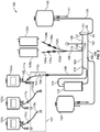
Fig. 1 , the systems described herein preferably include a disposable fluid circuit for use in the processing of the biological fluid (e.g., suspension of biological cells).Fluid circuit 100 is adapted for mounting onto a reusable hardware component, described below.Circuit 100 may include an integrated separation device, such as, but not limited to, thespinning membrane 101 described herein.Circuit 100 may also include filtrate bag orcontainer 140, retentate container orbag 150, and in-process container 122. Disposable fluid circuits of the type described below may further include sampling assemblies (not shown) for collecting samples of biological cells, "final" cell product, or other intermediate products obtained during the biological fluid processing. - As will be seen in the Figures and described in greater detail below, the disposable fluid processing circuit includes tubing that defines flow paths throughout the circuit, as well as access sites for sterile or other connection to containers of processing solutions, such as wash solutions, treating agents, and sources of the biological fluid. As will be apparent from the disclosure herein, a single source container 102 or multiple source containers (102a, 102b, 102c, as shown in
Fig. 2 ) may be attached in sterile fashion tocircuit 100. - As shown in
Figs. 1 and2 , the tubing ofcircuit 100 includes spaced tubing segments identified byreference numerals reusable hardware apparatus 200 discussed below. The containers and the plastic tubing are made of conventional medical grade plastic that can be sterilized by sterilization techniques commonly used in the medical field, such as, but not limited to, radiation or autoclaving. Plastic materials useful in the manufacture of containers and tubing in the circuits disclosed herein include plasticized polyvinyl chloride. Other useful materials include acrylics. In addition, certain polyolefins may also be used. - The biological fluid, such as a biological cell suspension, to be processed is typically provided in a source container 102, shown in
Fig. 1 as (initially) not connected to the disposable set. As noted above and shown inFig. 2 , one or more source container(s) (102a, 102b, 102c) may be attached (in sterile fashion) at the time of use. Source container(s) 102 may include one ormore access sites fluid circuit 100 atdocking site 104. Preferably, source containers may be attached in a sterile manner by employing sterile docking devices, such as the BioWelder, available from Sartorius AG, or the SCD IIB Tubing Welder, available from Terumo Medical Corporation. Asecond access port 105 may also be provided for extracting fluid from the source containers(s) 102. In accordance with the methods and systems described herein and as previously noted,multiple source containers - As shown in
Fig. 2 , wheremultiple source containers circuit 100 may optionally include a manifold 107 (shown in dashed lines), or other branched member 109 that receives and communicates withindividual source lines Manifold 107 or other branched member is in fluid communication withprimary source line 106, as shown. Flow through source line 110 (Fig. 1 ), or multiple,individual source lines Fig. 1 ) or 111a, 111b, and 111c (Fig. 2 ). - With further reference to
Figs. 1 and2 , tubing (source line) 106 is connected to downstream branched-connector 118. Branched-connector 118 communicates withtubing 106 andtubing 120, which provides a fluid flow path from "in-process"container 122, described in greater detail below.Tubing segment 124 extends from branched-connector 118 and is joined to a port of further downstream branched-connector 126. A separate flow path defined bytubing 128 is also connected to a port of branched-connector 126. - In accordance with the fluid circuit of
Figs. 1 and2 , one or more container(s) 135a/135b of priming/wash or other processing/treating solution may be attached tofluid circuit 100. As further shown inFigs. 1 and2 ,tubing 132a (defining a flow path) preferably includes and terminates in an access site such asspike connector 134a.Access sites 134a/134b are provided to establish flow communication withcontainers 135a/135b (shown inFigs. 1 and2 ) of a priming/wash fluid, such as saline or other solution. More preferably, flow communication betweentubing 132a and a container of priming/wash solution may be achieved by sterile connection device, such as, but not limited to, the previously mentioned Terumo SCD IIB. The priming/wash solution flows from the wash fluid source throughtubing segment 132a, and then passes throughtubing 128 to the input of the branched-connector 126 described above. The priming/wash solution then flows throughtubing segment 124 andsource line 106 to one or more source containers (SeeFigs. 1 and2 ). - It should be noted that
access site 134b may be used to establish fluid communication with additional containers of priming/wash solution (as shown) or other solutions and/or agents. - As further shown in
Figs. 1 and2 ,tubing segment 136 defines a flow path connected at one end to branched-connector 126 and to aninlet port 20 of theseparator 101. Preferably, in accordance with the present disclosure,separation device 101 is a spinning membrane separator of the type described inU.S. Patent No. 5,194,145 ,U.S. Patent No. 5,053,121 andPCT/US2012/028522 . - In an alternative embodiment,
separator 101 may utilize a different separation principle. For example,separator 101 may be a centrifuge. - As seen in
Figs. 1 and2 , spinningmembrane separator 101 has at least two outlet ports.Outlet 46 ofseparator 101 receives the separated filtrate (e.g., separated biological cells) and is connected totubing 138, which defines a flow path to filtrate/cell container 140. The filtrate/cell container may further includeconnection port 141 for sampling the contents within the filtrate/cell container 140. -
Separation device 101 preferably includes asecond outlet 48 that is connected totubing segment 142 for directing the retentate to branched-connector 144, which branches into and defines a flow path to one or more in-process containers 122 and/or a flow path to aretentate container 150. -
Fig. 3 shows thefront panel 201 of reusablehardware processing apparatus 200.Apparatus 200 may be of compact size suitable for placement on a table top of a lab bench and adapted for easy transport. Alternatively,apparatus 200 may be supported by a pedestal that can be wheeled to its desired location. In any event, as shown inFig. 3 ,apparatus 200 includes a plurality of peristaltic pumps, such aspumps front panel 201.Pump segments peristaltic pumps Figs. 1 and2 at the pump segments identified byreference numerals Apparatus 200 also includesclamps Clamps -
Apparatus 200 also includes several sensors to measure various conditions. The output of the sensors is utilized bydevice 200 to operate one or more processing or wash cycles. One or more pressure transducer sensor(s) 226 may be provided onapparatus 200 and may be associated with adisposable set 100 at certain points to monitor the pressure during a procedure.Pressure transducer 226 may be integrated into an in-line pressure monitoring site (at, for example, tubing segment 136), to monitor pressure insideseparator 101.Air detector sensor 238 may also be associated with thedisposable set 100, as necessary.Air detector 238 is optional and may be provided to detect the location of fluid/air interfaces. In accordance with the system priming described herein,air detector 238 may be used to generate an alert/alarm which may indicate incomplete priming or insufficient processing, requiring some correction and/or intervention by the operator. This is discussed in further detail below. -
Apparatus 200 includes weight scales 240, 242, 244, 246, 250, and 252 from which the cell container, in-process container, source container, and any additional container(s) (e.g., wash or priming solution container, retentate container, filtrate container, source container) may depend and be weighed. The weights of the containers are monitored by weight sensors and recorded during a washing or other procedure, including during the priming steps described herein. Where multiple source containers are to be processed, some of the source containers may be suspended from a standard I.V. pole or the like (in which case scale measurements would not be taken but pump strokes counted). From measurements of the weight sensors, the device, under the direction of the controller, determines whether each container is empty, partially full or full, and controls the components ofapparatus 200, such as the peristaltic pumps and clamps 210, 212, 214, 216, 218, 220, 222, and 224. In accordance with the present disclosure, weight sensors may provide volumes of biological fluid in source containers 102 (102a, 102b, 102c, etc.) and monitor the changing volume of priming/wash solutions in containers 135 (a and/or b) during priming, discussed in greater detail below. Alternatively, additional source containers 102 may be suspended from IV poles proximally located toapparatus 200. -
Apparatus 200 includes at least one drive unit or "spinner" 248 (Fig. 3 ), which causes the indirect driving of the spinningmembrane separator 101.Spinner 248 may consist of a drive motor connected and operated byapparatus 200, coupled to turn an annular magnetic drive member including at least a pair of permanent magnets. As the annular drive member is rotated, magnetic attraction between corresponding magnets within the housing of the spinning membrane separator cause the spinner within the housing of the spinning membrane separator to rotate. -
Fig. 5 is a schematic view of the control unit or "controller" 300 included indevice 200 of the present disclosure. Thecontroller 300 may include a microprocessor 304 (which may include multiple physical and/or virtual processors). According to other embodiments, thecontroller 300 may include one or more electrical circuits designed to carry out the actions described herein. In an embodiment,controller 300 may include a microprocessor and other circuits or circuitry. In addition, thecontroller 300 may include one ormore memories 306. The instructions by which themicroprocessor 304 is programmed may be stored on thememory 306 associated with themicroprocessor 304, which memory/memories 306 may include one or more tangible non-transitory computer readable memories, having computer executable instructions stored thereon, which when executed by themicroprocessor 304 may cause themicroprocessors 304 to carry out one or more actions as described herein. - As is also illustrated in
Fig. 5 ,controller 300 may be coupled to one or more of the structures described above, for example, to receive information (e.g., in the form of signals) from these structures or to provide commands (e.g., in the form of signals) to these structures to control the operation of the structures. As illustrated inFig. 5 , thecontroller 300 may be coupled to thescales Fig. 3 ) that hold solution containers or that are provided to collect blood components, the sensors associated withdevice 200, clamps washed, concentrated, or otherwise processed, and the at least oneinput 302 to receive information from those devices. Additionally, thecontroller 300 may be coupled topumps separator drive unit 248 to provide commands to those devices and to control their operation. It may also be possible that thecontroller 300 receives information from and provides commands to a given structure, such as one of the structures already mentioned. Thecontroller 300 may be directly electrically connected to these structures to be coupled to them, or thecontroller 300 may be directly connected to other intermediate equipment that is directly connected to these structures to be coupled to them. - The at least one
input 302 may include a number of different devices according to the embodiments described herein. For example, theinput 302 could include a keyboard or keypad by which a user may provide information and/or instructions to thecontroller 300. Alternatively, theinput 302 may be a touch screen, such as may be used in conjunction with avideo display 308 that is disposed on the front panel of the device 10, thevideo display 308 also being coupled to thecontroller 300. The assembly of the input/touch screen 302 andvideo display 308 may be one of the afore-mentioned structures to which thecontroller 300 is coupled from which thecontroller 300 receives information and to which thecontroller 300 provides commands. - Prior to introduction of biological cells into
separator 101, the system (under the direction of controller 300) may initiate priming of the flow paths of the circuit. The circuit may be primed with a priming solution, such as wash solution, suspended from one more hangers/weight scales of thereusable device 200. Prior to priming, the operator may enter a series of instructions to configure the priming of at least a portion of the fluid circuit based on the number of source containers, the total volume of source liquid to be processed, the source bag(s) capacity(ies), the number of "primes," the duration and interval of "pauses," the flow rate of the priming solution, etc. For example, afterfluid circuit 100 has been mounted onto hardware 200 (seeblock 400 ofFig. 6 ), the system has conducted the necessary checks, and one or more source containers 102 (102a, 102b, etc.) have been attached, as shown inFig. 6 , the operator may select (block 402) whether one source container of biological fluid is to be processed (block 430) or multiple containers of biological fluid are to be processed (block 404). The operator may also enter the total volume of source liquid to be processed, the capacity of the source containers, the volume of source liquid in each of the multiple source containers, and the composition of the source liquid. If multiple containers are to be processed, the operator may enter the number of source containers to be processed (and total volume) and may further select whether such multiple source containers will be primed sequentially (i.e.,bag 102a, followed bybag 102b, followed bybag 102c, etc., as shown in block 408) or simultaneously, as shown inblock 406. - As further shown in
Fig. 6 , the operator may also select the priming solution from among two or more solutions (blocks 410 and 420), the number of "primes" (block 412), the volume of priming solution and the flow rates of the priming solution. In addition, the operator may also introduce a "pause" between selected primes as well as the duration of such pause (blocks 416 and 424). Thus, for example, where sequential priming has been selected (block 408) the operator may introduce pauses of selected duration between priming ofcontainer - Where a single container of source solution is to be processed (block 430), the operator, after selecting the priming solution (block 432) may likewise select the number of "primes" and further select a flow rate and volume for each of the primes (block 436). Multiple primes may be desired to allow for osmotic balancing to occur. As with the priming of multiple source containers, the operator may introduce pauses of selected duration between the multiple "primes" to allow for mixing of the biological fluid with the priming solution.
- The steps described above are not limited to the specific order presented. For example, selection of the priming solution may be made prior to selecting whether to prime multiple source lines and containers sequentially or simultaneously.
- Once the priming instructions have been entered, the operator may initiate the priming cycle (
blocks controller 300 effects the necessary opening and closing ofclamps pump close clamps 111, 111a-111c as necessary to allow flow of priming solution to the one or more source containers. - In accordance with the present disclosure, the methods and systems described herein may include an alert/alarm condition which may be indicative of incomplete or ineffective priming.
Air detector 238 may be programmed to detect the presence of air at a given point in time during cell processing. For example, if the volume of source liquid and/or the number of source containers has been entered incorrectly (e.g., fewer than the actual number of containers or less than the actual volume entered),air detector 238 may detect the presence of air sooner than expected. This may generate an alert/alarm requiring the operator to check whether the data entered matches the actual source volume, number of source containers, or that connections to the source containers have been properly made and confirm whether or not all source lines and source containers have been effectively primed, processed, or rinsed. - The description provided above is intended for illustrative purposes, and is not intended to limit the scope of the disclosure to any particular method, system, apparatus or device described herein.
Claims (15)
- A method for priming at least a portion of a fluid circuit (100) of a biological fluid processing system comprising:a. pumping a priming solution from one or more containers of priming solution (135a) through a portion of said fluid circuit (100);b. delivering a selected volume of priming solution through a source line (106, 110) of said fluid circuit to one or more containers (102, 102a-c) of a biological fluid containing biological cells, wherein the priming solution serves to remove air that may reside within the flow paths of the circuit;c. pausing the delivery of the priming solution for a selected period of time;d. mixing said priming solution with said biological fluid containing biological cells in said source container(s); ande. delivering a selected volume of priming solution to a source line (106, 110) of said fluid circuit after said pausing of said priming solution delivery for a selected period of time.
- The method of Claim 1 further comprising delivering said selected volume of priming solution at a pre-determined rate.
- The method of any one of Claims 1 and 2 comprising providing said biological fluid containing biological cells from multiple source containers (102 a-c).
- The method of Claim 3 comprising delivering a priming solution to a source line (110 a-c) communicating with each of said multiple source containers (102 a-c).
- The method of Claim 4 comprising delivering said priming solution to each of said multiple source containers (102 a-c).
- The method of any one of Claims 1 through 5 comprising delivering said priming solution before and after said pausing at different flow rates.
- The method of any one of Claims 3 through 5 comprising delivering said priming solution to each of said multiple source containers (102 a-c) simultaneously.
- The method of any on one of Claims 3 through 5 comprising delivering said priming solution to each of said multiple source containers (102 a-c) sequentially.
- An automated system for the processing of biological fluid containing biological cells comprising:a. a reusable hardware unit comprising a plurality of pumps and separation device drive unit for receiving a separation device (101);b. a disposable fluid circuit (100) mountable on said reusable hardware unit, said disposable fluid circuit including tubing defining a flow path between a container (135a) of a priming solution and one or more source containers (102, 102 a-c) of a biological fluid containing biological cells; andc. a controller configured to control the delivery of a selected volume of said priming solution through a source line to said source container, wherein said controller is configured to effect a pause of said delivery of said priming solution.
- The system of Claim 9 wherein said controller is configured to determine the volume of priming solution to be delivered to said source container (102).
- The system of Claim 10 wherein said controller is configured to control the delivery of said priming solution based upon one or more of (a) the total volume of the biological fluid containing biological cells (b) the number of source containers (102, 102 a-c) of biological fluid containing biological cells (c) the duration and interval of said one or more pauses and the number of primes.
- The system of Claim 11 wherein said controller is configured to deliver said priming solution incrementally and effect said one or more pauses of a predetermined duration during said incremental delivery of said priming solution.
- The system of any one of Claims 9 through 12 wherein said controller is configured to deliver said priming solution at variable flow rate.
- The system of any one of Claims 9 through 13 wherein said disposable fluid circuit is configured for attachment to multiple source containers (102 a-c) of biological fluid containing biological cells and said disposable fluid circuit includes a manifold (107) providing fluid communication with said multiple source containers (102 a-c).
- The system of any one of Claims 9 through 14 further comprising a sensor for detecting the presence of air within said fluid circuit and said controller is configured to effect re-priming of at least a portion of said disposable fluid circuit in response to said detecting.
Applications Claiming Priority (1)
| Application Number | Priority Date | Filing Date | Title |
|---|---|---|---|
| US201662342757P | 2016-05-27 | 2016-05-27 |
Publications (2)
| Publication Number | Publication Date |
|---|---|
| EP3248627A1 EP3248627A1 (en) | 2017-11-29 |
| EP3248627B1 true EP3248627B1 (en) | 2020-02-26 |
Family
ID=58714973
Family Applications (1)
| Application Number | Title | Priority Date | Filing Date |
|---|---|---|---|
| EP17171302.7A Active EP3248627B1 (en) | 2016-05-27 | 2017-05-16 | Systems and methods for priming a fluid circuit |
Country Status (2)
| Country | Link |
|---|---|
| US (1) | US11357900B2 (en) |
| EP (1) | EP3248627B1 (en) |
Families Citing this family (3)
| Publication number | Priority date | Publication date | Assignee | Title |
|---|---|---|---|---|
| EP3476754B1 (en) * | 2017-10-24 | 2019-10-02 | Grifols Worldwide Operations Limited | Apparatus for gravity-emptying bottles containing frozen blood product comprising a unit for monitoring emptying and emptying method |
| BR112020013848A2 (en) * | 2018-01-08 | 2020-12-01 | Iovance Biotherapeutics, Inc. | methods for expanding tumor-infiltrating lymphocytes and for treating an individual with cancer, tumor-infiltrating lymphocyte population, and, method for evaluating transcription factors |
| US11713446B2 (en) | 2018-01-08 | 2023-08-01 | Iovance Biotherapeutics, Inc. | Processes for generating TIL products enriched for tumor antigen-specific T-cells |
Family Cites Families (11)
| Publication number | Priority date | Publication date | Assignee | Title |
|---|---|---|---|---|
| JPS61501494A (en) | 1984-03-21 | 1986-07-24 | マクロ−リン、ウイリアム フランシス | Equipment for separating substances from suspensions |
| US4721564A (en) * | 1985-10-22 | 1988-01-26 | Kuraray Co., Ltd. | Apparatus for the filtration of plasma from blood |
| EP0277994B1 (en) | 1986-08-11 | 1991-09-04 | BAXTER INTERNATIONAL INC. (a Delaware corporation) | Blood cell washing systems and methods |
| CA2101951A1 (en) * | 1991-12-18 | 1993-06-19 | David M. Kelso | Systems for conducting multiple analytical procedures using a central processing hub |
| US8562908B2 (en) * | 2007-06-29 | 2013-10-22 | Baxter International Inc. | Devices, systems, and methods for cleaning, disinfecting, rinsing, and priming blood separation devices and associated fluid lines |
| WO2013043433A2 (en) | 2011-09-22 | 2013-03-28 | Fenwal, Inc. | Disposable fluid circuits and methods for cell washing |
| RU2615536C2 (en) | 2011-03-11 | 2017-04-05 | Фенвал, Инк. | Devices of membrane separation, systems and methods that employ specified device |
| US9164078B2 (en) * | 2012-06-15 | 2015-10-20 | Fenwal, Inc. | Process for predicting hematocrit of whole blood using IR light |
| US9861736B2 (en) * | 2013-05-31 | 2018-01-09 | Fenwal, Inc. | Methods for extracting platelet-rich plasma for therapeutic injection |
| US10400216B2 (en) | 2014-12-18 | 2019-09-03 | Fenwal, Inc. | Methods for cell washing with on-line dilution of cell feed |
| US10329530B2 (en) * | 2016-01-18 | 2019-06-25 | Fenwal, Inc. | Cell washing system and methods for washing small volumes of cells |
-
2017
- 2017-05-16 EP EP17171302.7A patent/EP3248627B1/en active Active
- 2017-05-19 US US15/600,447 patent/US11357900B2/en active Active
Non-Patent Citations (1)
| Title |
|---|
| None * |
Also Published As
| Publication number | Publication date |
|---|---|
| US11357900B2 (en) | 2022-06-14 |
| US20170340799A1 (en) | 2017-11-30 |
| EP3248627A1 (en) | 2017-11-29 |
Similar Documents
| Publication | Publication Date | Title |
|---|---|---|
| US11901068B2 (en) | Cell processing methods with process parameter control | |
| US11672891B2 (en) | Cell processing system and method with preliminary process evaluation | |
| EP3248627B1 (en) | Systems and methods for priming a fluid circuit | |
| EP3034105B1 (en) | Methods for cell washing with on-line dilution of cell feed | |
| US10251990B2 (en) | System and method for processing, incubating, and/or selecting biological cells | |
| US11678825B2 (en) | Methods and systems for collecting samples in a photopheresis procedure | |
| EP3295972B1 (en) | Cell processing system and method with fill options | |
| EP3461511B1 (en) | Systems and methods for processing large volumes of biological fluid | |
| EP3111972B1 (en) | Systems and methods for monitoring and correcting defects and tubing installation errors for blood processing systems | |
| EP3000495B1 (en) | Systems for controlling the return phase of a blood separation procedure | |
| EP3525214A1 (en) | Custom data fields for automated apheresis procedures | |
| US10221385B2 (en) | Cell processing system and method with post-separation cell count control | |
| JP2023154416A (en) | System and method for implementing different versions of blood separation procedure |
Legal Events
| Date | Code | Title | Description |
|---|---|---|---|
| PUAI | Public reference made under article 153(3) epc to a published international application that has entered the european phase |
Free format text: ORIGINAL CODE: 0009012 |
|
| STAA | Information on the status of an ep patent application or granted ep patent |
Free format text: STATUS: THE APPLICATION HAS BEEN PUBLISHED |
|
| AK | Designated contracting states |
Kind code of ref document: A1 Designated state(s): AL AT BE BG CH CY CZ DE DK EE ES FI FR GB GR HR HU IE IS IT LI LT LU LV MC MK MT NL NO PL PT RO RS SE SI SK SM TR |
|
| AX | Request for extension of the european patent |
Extension state: BA ME |
|
| STAA | Information on the status of an ep patent application or granted ep patent |
Free format text: STATUS: REQUEST FOR EXAMINATION WAS MADE |
|
| 17P | Request for examination filed |
Effective date: 20180528 |
|
| RBV | Designated contracting states (corrected) |
Designated state(s): AL AT BE BG CH CY CZ DE DK EE ES FI FR GB GR HR HU IE IS IT LI LT LU LV MC MK MT NL NO PL PT RO RS SE SI SK SM TR |
|
| STAA | Information on the status of an ep patent application or granted ep patent |
Free format text: STATUS: EXAMINATION IS IN PROGRESS |
|
| 17Q | First examination report despatched |
Effective date: 20181221 |
|
| GRAP | Despatch of communication of intention to grant a patent |
Free format text: ORIGINAL CODE: EPIDOSNIGR1 |
|
| STAA | Information on the status of an ep patent application or granted ep patent |
Free format text: STATUS: GRANT OF PATENT IS INTENDED |
|
| INTG | Intention to grant announced |
Effective date: 20190916 |
|
| GRAS | Grant fee paid |
Free format text: ORIGINAL CODE: EPIDOSNIGR3 |
|
| GRAA | (expected) grant |
Free format text: ORIGINAL CODE: 0009210 |
|
| STAA | Information on the status of an ep patent application or granted ep patent |
Free format text: STATUS: THE PATENT HAS BEEN GRANTED |
|
| AK | Designated contracting states |
Kind code of ref document: B1 Designated state(s): AL AT BE BG CH CY CZ DE DK EE ES FI FR GB GR HR HU IE IS IT LI LT LU LV MC MK MT NL NO PL PT RO RS SE SI SK SM TR |
|
| REG | Reference to a national code |
Ref country code: GB Ref legal event code: FG4D |
|
| REG | Reference to a national code |
Ref country code: CH Ref legal event code: EP |
|
| REG | Reference to a national code |
Ref country code: DE Ref legal event code: R096 Ref document number: 602017012136 Country of ref document: DE |
|
| REG | Reference to a national code |
Ref country code: AT Ref legal event code: REF Ref document number: 1236862 Country of ref document: AT Kind code of ref document: T Effective date: 20200315 |
|
| REG | Reference to a national code |
Ref country code: IE Ref legal event code: FG4D |
|
| PG25 | Lapsed in a contracting state [announced via postgrant information from national office to epo] |
Ref country code: RS Free format text: LAPSE BECAUSE OF FAILURE TO SUBMIT A TRANSLATION OF THE DESCRIPTION OR TO PAY THE FEE WITHIN THE PRESCRIBED TIME-LIMIT Effective date: 20200226 Ref country code: FI Free format text: LAPSE BECAUSE OF FAILURE TO SUBMIT A TRANSLATION OF THE DESCRIPTION OR TO PAY THE FEE WITHIN THE PRESCRIBED TIME-LIMIT Effective date: 20200226 Ref country code: NO Free format text: LAPSE BECAUSE OF FAILURE TO SUBMIT A TRANSLATION OF THE DESCRIPTION OR TO PAY THE FEE WITHIN THE PRESCRIBED TIME-LIMIT Effective date: 20200526 |
|
| REG | Reference to a national code |
Ref country code: NL Ref legal event code: MP Effective date: 20200226 |
|
| REG | Reference to a national code |
Ref country code: LT Ref legal event code: MG4D |
|
| PG25 | Lapsed in a contracting state [announced via postgrant information from national office to epo] |
Ref country code: BG Free format text: LAPSE BECAUSE OF FAILURE TO SUBMIT A TRANSLATION OF THE DESCRIPTION OR TO PAY THE FEE WITHIN THE PRESCRIBED TIME-LIMIT Effective date: 20200526 Ref country code: HR Free format text: LAPSE BECAUSE OF FAILURE TO SUBMIT A TRANSLATION OF THE DESCRIPTION OR TO PAY THE FEE WITHIN THE PRESCRIBED TIME-LIMIT Effective date: 20200226 Ref country code: GR Free format text: LAPSE BECAUSE OF FAILURE TO SUBMIT A TRANSLATION OF THE DESCRIPTION OR TO PAY THE FEE WITHIN THE PRESCRIBED TIME-LIMIT Effective date: 20200527 Ref country code: SE Free format text: LAPSE BECAUSE OF FAILURE TO SUBMIT A TRANSLATION OF THE DESCRIPTION OR TO PAY THE FEE WITHIN THE PRESCRIBED TIME-LIMIT Effective date: 20200226 Ref country code: IS Free format text: LAPSE BECAUSE OF FAILURE TO SUBMIT A TRANSLATION OF THE DESCRIPTION OR TO PAY THE FEE WITHIN THE PRESCRIBED TIME-LIMIT Effective date: 20200626 Ref country code: LV Free format text: LAPSE BECAUSE OF FAILURE TO SUBMIT A TRANSLATION OF THE DESCRIPTION OR TO PAY THE FEE WITHIN THE PRESCRIBED TIME-LIMIT Effective date: 20200226 |
|
| PG25 | Lapsed in a contracting state [announced via postgrant information from national office to epo] |
Ref country code: NL Free format text: LAPSE BECAUSE OF FAILURE TO SUBMIT A TRANSLATION OF THE DESCRIPTION OR TO PAY THE FEE WITHIN THE PRESCRIBED TIME-LIMIT Effective date: 20200226 |
|
| PG25 | Lapsed in a contracting state [announced via postgrant information from national office to epo] |
Ref country code: ES Free format text: LAPSE BECAUSE OF FAILURE TO SUBMIT A TRANSLATION OF THE DESCRIPTION OR TO PAY THE FEE WITHIN THE PRESCRIBED TIME-LIMIT Effective date: 20200226 Ref country code: EE Free format text: LAPSE BECAUSE OF FAILURE TO SUBMIT A TRANSLATION OF THE DESCRIPTION OR TO PAY THE FEE WITHIN THE PRESCRIBED TIME-LIMIT Effective date: 20200226 Ref country code: SM Free format text: LAPSE BECAUSE OF FAILURE TO SUBMIT A TRANSLATION OF THE DESCRIPTION OR TO PAY THE FEE WITHIN THE PRESCRIBED TIME-LIMIT Effective date: 20200226 Ref country code: DK Free format text: LAPSE BECAUSE OF FAILURE TO SUBMIT A TRANSLATION OF THE DESCRIPTION OR TO PAY THE FEE WITHIN THE PRESCRIBED TIME-LIMIT Effective date: 20200226 Ref country code: RO Free format text: LAPSE BECAUSE OF FAILURE TO SUBMIT A TRANSLATION OF THE DESCRIPTION OR TO PAY THE FEE WITHIN THE PRESCRIBED TIME-LIMIT Effective date: 20200226 Ref country code: SK Free format text: LAPSE BECAUSE OF FAILURE TO SUBMIT A TRANSLATION OF THE DESCRIPTION OR TO PAY THE FEE WITHIN THE PRESCRIBED TIME-LIMIT Effective date: 20200226 Ref country code: CZ Free format text: LAPSE BECAUSE OF FAILURE TO SUBMIT A TRANSLATION OF THE DESCRIPTION OR TO PAY THE FEE WITHIN THE PRESCRIBED TIME-LIMIT Effective date: 20200226 Ref country code: LT Free format text: LAPSE BECAUSE OF FAILURE TO SUBMIT A TRANSLATION OF THE DESCRIPTION OR TO PAY THE FEE WITHIN THE PRESCRIBED TIME-LIMIT Effective date: 20200226 Ref country code: PT Free format text: LAPSE BECAUSE OF FAILURE TO SUBMIT A TRANSLATION OF THE DESCRIPTION OR TO PAY THE FEE WITHIN THE PRESCRIBED TIME-LIMIT Effective date: 20200719 |
|
| REG | Reference to a national code |
Ref country code: AT Ref legal event code: MK05 Ref document number: 1236862 Country of ref document: AT Kind code of ref document: T Effective date: 20200226 |
|
| REG | Reference to a national code |
Ref country code: DE Ref legal event code: R097 Ref document number: 602017012136 Country of ref document: DE |
|
| PLBE | No opposition filed within time limit |
Free format text: ORIGINAL CODE: 0009261 |
|
| STAA | Information on the status of an ep patent application or granted ep patent |
Free format text: STATUS: NO OPPOSITION FILED WITHIN TIME LIMIT |
|
| PG25 | Lapsed in a contracting state [announced via postgrant information from national office to epo] |
Ref country code: CH Free format text: LAPSE BECAUSE OF NON-PAYMENT OF DUE FEES Effective date: 20200531 Ref country code: IT Free format text: LAPSE BECAUSE OF FAILURE TO SUBMIT A TRANSLATION OF THE DESCRIPTION OR TO PAY THE FEE WITHIN THE PRESCRIBED TIME-LIMIT Effective date: 20200226 Ref country code: AT Free format text: LAPSE BECAUSE OF FAILURE TO SUBMIT A TRANSLATION OF THE DESCRIPTION OR TO PAY THE FEE WITHIN THE PRESCRIBED TIME-LIMIT Effective date: 20200226 Ref country code: MC Free format text: LAPSE BECAUSE OF FAILURE TO SUBMIT A TRANSLATION OF THE DESCRIPTION OR TO PAY THE FEE WITHIN THE PRESCRIBED TIME-LIMIT Effective date: 20200226 Ref country code: LI Free format text: LAPSE BECAUSE OF NON-PAYMENT OF DUE FEES Effective date: 20200531 |
|
| 26N | No opposition filed |
Effective date: 20201127 |
|
| PG25 | Lapsed in a contracting state [announced via postgrant information from national office to epo] |
Ref country code: PL Free format text: LAPSE BECAUSE OF FAILURE TO SUBMIT A TRANSLATION OF THE DESCRIPTION OR TO PAY THE FEE WITHIN THE PRESCRIBED TIME-LIMIT Effective date: 20200226 Ref country code: SI Free format text: LAPSE BECAUSE OF FAILURE TO SUBMIT A TRANSLATION OF THE DESCRIPTION OR TO PAY THE FEE WITHIN THE PRESCRIBED TIME-LIMIT Effective date: 20200226 |
|
| REG | Reference to a national code |
Ref country code: BE Ref legal event code: MM Effective date: 20200531 |
|
| PG25 | Lapsed in a contracting state [announced via postgrant information from national office to epo] |
Ref country code: LU Free format text: LAPSE BECAUSE OF NON-PAYMENT OF DUE FEES Effective date: 20200516 |
|
| PG25 | Lapsed in a contracting state [announced via postgrant information from national office to epo] |
Ref country code: IE Free format text: LAPSE BECAUSE OF NON-PAYMENT OF DUE FEES Effective date: 20200516 |
|
| PG25 | Lapsed in a contracting state [announced via postgrant information from national office to epo] |
Ref country code: BE Free format text: LAPSE BECAUSE OF NON-PAYMENT OF DUE FEES Effective date: 20200531 |
|
| PG25 | Lapsed in a contracting state [announced via postgrant information from national office to epo] |
Ref country code: TR Free format text: LAPSE BECAUSE OF FAILURE TO SUBMIT A TRANSLATION OF THE DESCRIPTION OR TO PAY THE FEE WITHIN THE PRESCRIBED TIME-LIMIT Effective date: 20200226 Ref country code: MT Free format text: LAPSE BECAUSE OF FAILURE TO SUBMIT A TRANSLATION OF THE DESCRIPTION OR TO PAY THE FEE WITHIN THE PRESCRIBED TIME-LIMIT Effective date: 20200226 Ref country code: CY Free format text: LAPSE BECAUSE OF FAILURE TO SUBMIT A TRANSLATION OF THE DESCRIPTION OR TO PAY THE FEE WITHIN THE PRESCRIBED TIME-LIMIT Effective date: 20200226 |
|
| PG25 | Lapsed in a contracting state [announced via postgrant information from national office to epo] |
Ref country code: MK Free format text: LAPSE BECAUSE OF FAILURE TO SUBMIT A TRANSLATION OF THE DESCRIPTION OR TO PAY THE FEE WITHIN THE PRESCRIBED TIME-LIMIT Effective date: 20200226 Ref country code: AL Free format text: LAPSE BECAUSE OF FAILURE TO SUBMIT A TRANSLATION OF THE DESCRIPTION OR TO PAY THE FEE WITHIN THE PRESCRIBED TIME-LIMIT Effective date: 20200226 |
|
| P01 | Opt-out of the competence of the unified patent court (upc) registered |
Effective date: 20230515 |
|
| PGFP | Annual fee paid to national office [announced via postgrant information from national office to epo] |
Ref country code: FR Payment date: 20230525 Year of fee payment: 7 Ref country code: DE Payment date: 20230530 Year of fee payment: 7 |
|
| PGFP | Annual fee paid to national office [announced via postgrant information from national office to epo] |
Ref country code: GB Payment date: 20230529 Year of fee payment: 7 |