EP3246455B1 - Laundry treating machine comprising a removable de-fluff filter - Google Patents
Laundry treating machine comprising a removable de-fluff filter Download PDFInfo
- Publication number
- EP3246455B1 EP3246455B1 EP16169878.2A EP16169878A EP3246455B1 EP 3246455 B1 EP3246455 B1 EP 3246455B1 EP 16169878 A EP16169878 A EP 16169878A EP 3246455 B1 EP3246455 B1 EP 3246455B1
- Authority
- EP
- European Patent Office
- Prior art keywords
- fluff
- filter
- airflow
- hollow chamber
- laundry machine
- Prior art date
- Legal status (The legal status is an assumption and is not a legal conclusion. Google has not performed a legal analysis and makes no representation as to the accuracy of the status listed.)
- Active
Links
- 238000001035 drying Methods 0.000 claims description 75
- 238000001914 filtration Methods 0.000 claims description 65
- 239000002245 particle Substances 0.000 claims description 14
- 239000012530 fluid Substances 0.000 claims description 11
- 238000009825 accumulation Methods 0.000 claims description 6
- 238000004891 communication Methods 0.000 claims description 6
- 230000000750 progressive effect Effects 0.000 claims description 2
- 230000002093 peripheral effect Effects 0.000 description 12
- 230000008878 coupling Effects 0.000 description 9
- 238000010168 coupling process Methods 0.000 description 9
- 238000005859 coupling reaction Methods 0.000 description 9
- 238000010438 heat treatment Methods 0.000 description 8
- 239000000463 material Substances 0.000 description 7
- 238000007789 sealing Methods 0.000 description 7
- 238000005406 washing Methods 0.000 description 5
- 230000000903 blocking effect Effects 0.000 description 4
- 238000005259 measurement Methods 0.000 description 4
- 229920000642 polymer Polymers 0.000 description 4
- 238000000034 method Methods 0.000 description 3
- 239000004695 Polyether sulfone Substances 0.000 description 2
- 239000004743 Polypropylene Substances 0.000 description 2
- 238000004026 adhesive bonding Methods 0.000 description 2
- 238000003780 insertion Methods 0.000 description 2
- 230000037431 insertion Effects 0.000 description 2
- 229920006393 polyether sulfone Polymers 0.000 description 2
- 230000008569 process Effects 0.000 description 2
- 239000012858 resilient material Substances 0.000 description 2
- -1 Polypropylene Polymers 0.000 description 1
- 239000004676 acrylonitrile butadiene styrene Substances 0.000 description 1
- 238000005452 bending Methods 0.000 description 1
- 238000007664 blowing Methods 0.000 description 1
- 238000004140 cleaning Methods 0.000 description 1
- 238000001816 cooling Methods 0.000 description 1
- 230000003247 decreasing effect Effects 0.000 description 1
- 230000001419 dependent effect Effects 0.000 description 1
- 239000003599 detergent Substances 0.000 description 1
- 230000001627 detrimental effect Effects 0.000 description 1
- 238000005516 engineering process Methods 0.000 description 1
- 230000002708 enhancing effect Effects 0.000 description 1
- 238000011010 flushing procedure Methods 0.000 description 1
- 230000001939 inductive effect Effects 0.000 description 1
- 238000002347 injection Methods 0.000 description 1
- 239000007924 injection Substances 0.000 description 1
- 238000010412 laundry washing Methods 0.000 description 1
- 238000012423 maintenance Methods 0.000 description 1
- 230000007257 malfunction Effects 0.000 description 1
- 230000010355 oscillation Effects 0.000 description 1
- 239000004033 plastic Substances 0.000 description 1
- 229920003023 plastic Polymers 0.000 description 1
- 239000004417 polycarbonate Substances 0.000 description 1
- 229920000515 polycarbonate Polymers 0.000 description 1
- 229920001155 polypropylene Polymers 0.000 description 1
- 238000003825 pressing Methods 0.000 description 1
- 230000009467 reduction Effects 0.000 description 1
- 230000003014 reinforcing effect Effects 0.000 description 1
- 239000000243 solution Substances 0.000 description 1
- 238000003860 storage Methods 0.000 description 1
- XLYOFNOQVPJJNP-UHFFFAOYSA-N water Substances O XLYOFNOQVPJJNP-UHFFFAOYSA-N 0.000 description 1
Images


Classifications
-
- D—TEXTILES; PAPER
- D06—TREATMENT OF TEXTILES OR THE LIKE; LAUNDERING; FLEXIBLE MATERIALS NOT OTHERWISE PROVIDED FOR
- D06F—LAUNDERING, DRYING, IRONING, PRESSING OR FOLDING TEXTILE ARTICLES
- D06F58/00—Domestic laundry dryers
- D06F58/20—General details of domestic laundry dryers
- D06F58/22—Lint collecting arrangements
Definitions
- the present invention relates to laundry treatment appliances or machines.
- the present invention refers to appliances for drying laundry, both for domestic and professional use. More particularly, the present invention relates to a de-fluff filter.
- Drying and washing/drying laundry machines - which will be referred to simply as laundry machine in the following - typically comprise a casing substantially parallepiped-shaped.
- the casing accommodates a laundry treating chamber, comprising a drum, generally rotatable, apt to contain the laundry to be dried, in the case of a washing/drying laundry machine, the drum is rotatably contained in a tub.
- a front panel of the casing has a loading opening to access the treating chamber for loading/unloading the laundry, and a door is provided for closing the loading opening, particularly during the laundry machine operation.
- the casing also accommodates the electrical, electronic, mechanical, and hydraulic components necessary for the operation of the laundry machine.
- laundry-drying capable machines features an air circuit (comprising, for example, fans, air ducts, a moisture condensing unit, a heating unit, etc .) adapted to heat air, blow it into the drum where it removes moisture from the laundry, suck out from the drum the moisturized air, de-moisturize the air and reiterate such actions thereby performing a laundry drying cycle.
- an air circuit comprising, for example, fans, air ducts, a moisture condensing unit, a heating unit, etc .
- the laundry under treatment typically loses lint particles or fluff.
- the fluff is generally light and tiny, thus it can be brought out from the drum by the hot drying air flowing therein and then into the air circuit.
- the fluff is likely to accumulate therein, thereby possibly obstructing air ducts of the air circuit or negatively affecting the operation of one or more of its components (e.g., fluff may deposit on a fan, to the extent of possibly causing the latter to operate with a lower efficiency or completely stop it).
- fluff accumulation has a detrimental effect on the laundry drying machine operation.
- de-fluff filters have been designed for the purpose of retaining the fluff so as to prevent it from damaging the laundry machine components. Nevertheless, the de-fluff filter needs to be periodically cleaned to avoid it to get clogged, event that may reduce the laundry machine efficiency or even cause a laundry drying machine malfunction, at least of the air circuit thereof.
- the de-fluff filter is usually removably accommodated in a filter seat within the air circuit, for example in a position located at the front of the casing in a top portion thereof, i.e. in positions that are easily reachable by a user.
- fluff may still amass within the de-fluff filter during the course of a single laundry drying machine operation in a quantity that may affect the efficiency of the laundry machine.
- fluff trapped in the de-fluff filter may hinder the flow of air within the air circuit of the laundry drying machine.
- trapped fluff may reduce a flow rate through the de-fluff filter, thus causing localized pressure peaks and drops in the air circuit and subsequent localized /or temperature rise along the air circuit.
- EP 2 843 103 A1 discloses a laundry machine with a de-fluff filter, which comprises a filter box and a lid defining a hollow chamber within.
- a filtering mesh is arranged on an outlet portion of the box on a transversal sidewall.
- the lid comprises air guiding blades protruding from a lower side of the lid towards the inside of the filter box, subdividing the hollow chamber of the filter box in sub-chambers.
- the sub-chambers have a sectional area that increases along the drying air flow direction path, in such a way to distribute evenly the drying air flow inside the filter box for homogenously directing the drying air flow towards the filtering mesh.
- US 5,651,188 A discloses a lint storage system comprising a lint basket with one hollow chamber therein.
- the lower and side surfaces of the basket comprise outlet openings covered with filter elements, wherein the size of the outlet openings increases from the air inlet end of the basket to the outlet end of the basket.
- the Applicant has tackled the problem of devising a laundry machine comprising a de-fluff filter arrangement capable to overcome, at least partly, the drawbacks of the prior art.
- the Applicant has devised a de-fluff filter that is easy to insert into, and to remove out of a corresponding housing, and which is able to ensure a substantially homogenous flow rate of air therethrough during the laundry machine operation.
- the laundry machine comprises: a casing; inside the casing, a laundry treating chamber adapted to contain the laundry to be dried; an air circuit in fluid communication with the laundry treating chamber through an inlet opening, and defining an air-path for the flow of drying air between said inlet and outlet openings; a filter housing for removably accommodating a de-fluff filter, said filter housing being provided in the air-path and being accessible through a housing aperture.
- the de-fluff filter is arranged for trapping fluff or lint particles carried by the flow of drying air crossing said de-fluff filter, the de-fluff filter comprises a filtering element and a hollow chamber which comprises an inlet aperture and an outlet portion.
- the de-fluff filter further comprises an airflow diverter which: divides the hollow chamber of the de-fluff filter in a first portion and a second portion, and diverts the flow of drying air entering the de-fluff filter towards the first portion of the hollow chamber or towards the second portion of the hollow chamber according to an amount of fluff currently trapped in the at least one filtering element.
- the airflow diverter comprises at least one filtering element for filtering the flow of drying air entering the first portion of the hollow chamber of the de-fluff filter thereby trapping fluff or lint particles.
- the majority of drying air flow entering the de-fluff filter is directed to the first portion of the hollow chamber in a first part of a drying process.
- the airflow diverter is arranged for diverting the flow of drying air entering the de-fluff filter from the first portion of the hollow chamber towards the second portion of the hollow chamber according to an amount of fluff currently trapped in first portion of the hollow chamber.
- the first portion and the second portion of the hollow chamber define, for the flow of drying air, two paths causing a different amount of energy losses to the fluid portions entering the first and the second portion respectively.
- the amount of energy losses caused by the first portion is lower than the amount of energy losses caused by the second portion.
- the progressive accumulation of fluff or lint particles in the first region of the hollow chamber increases the amount of energy losses to the fluid portion entering the first portion up to make such amount greater than the amount of energy losses caused by the second portion.
- the airflow diverter traps fluff or lint particles at least up to a threshold amount that causes substantially the whole airflow to divert from the first region to the second region of the hollow chamber.
- said threshold amount of fluff or lint particles is a function of at least one among: a size of the first region, a size of the hollow chamber, a size of the airflow diverter and a size of a filtering element provided in the airflow diverter or in the de-fluff filter.
- the airflow diverter comprises a peripheral frame and at least one separating element, the peripheral frame and at least one separating element defining two or more filtering elements.
- the peripheral frame is integral with the at least one separating element.
- the peripheral frame and the at least one separating element comprise a first half and a second half, each half being symmetrical to the other and designed to couple with the other half along a longitudinal symmetry plane of the airflow diverter.
- the airflow diverter is removably mounted in the hollow chamber of the de-fluff filter.
- the airflow diverter further comprises at least one foot element arranged for coupling with the de-fluff.
- the de-fluff filter further comprises at least one foot receptacle.
- the at least one foot element is arranged for coupling with said at least one foot receptacle.
- the de-fluff filter further comprises one or more retaining brackets for holding the airflow diverter in a working position within the hollow chamber.
- the de-fluff filter further comprises a filter box and a lid hinged to the filter box for pivoting from an opening position to a closed position thereby selectively closing a top aperture of the filter box, the hollow chamber being defined by the filter box and by the lid in the closed position.
- the airflow diverter is arranged for being flush both with the lid and with a bottom wall of the filter box opposite to the lid.
- the lid comprises a plurality of lid ridges protruding towards the filter box once the lid is in the closed position.
- the filter box comprises corresponding box ridges protruding towards the lid once the lid is in the closed position, the lid ridges being arranged for interspersing with the box ridges once the lid is in the closed position thereby forming a meandering path capable of hindering the passage of fluff.
- the hollow chamber is delimited by a guiding wall and a sidewall, the airflow diverter being arranged therebetween so as to form with at least one of said guiding wall and sidewall a path having a convergent portion along the direction of the flow of air.
- the airflow diverter is movable from a first position, in which the airflow is directed into a first portion of the de-fluff filter, to a second position, in which the airflow is directed into a second portion of the de-fluff filter.
- the airflow diverter is deformable between a rest configuration, in which the airflow is directed into a first portion of the de-fluff filter, and a deformed configuration, in which the airflow is directed into a second portion of the de-fluff filter.
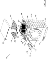
- Figure 1 is a perspective view of a laundry machine, globally denoted as 100 , according to an embodiment of the present invention.
- the laundry machine 100 comprises a laundry treatment chamber 105 for accommodating the items to be dried or washed and dried, such as clothes, garments, linen, and similar laundry items.
- the laundry treatment chamber 105 includes a drum (not shown) rotatably mounted inside a machine cabinet or casing 110 , and in case the laundry machine 100 is a washing/drying laundry machine the drum is arranged within a tub (not shown) housed in the machine casing 110 .
- the casing 110 generally accommodates all the electrical, electronic, mechanical, and hydraulic components necessary for the operation of the laundry machine.
- the casing 110 has generically a parallelepiped shape, with a front wall 115 , two side walls 120 (only one visible in Figure 1 ), a rear wall (not visible), a basement and a top element, or simply top 125 .
- the front wall 115 is provided with an opening for accessing the drum and with an associated door 117 for closing the opening.
- a machine control panel 130 is located, and, aside the control panel 130, a drawer 135 is provided, which is part of a washing treatment products dispensing arrangement, for loading laundry washing treatment products like detergents and softeners.
- the top 125 closes the casing 110 from above, and defines a worktop.
- a de-fluff filter (aesthetic) cover 140 is exposed on the control panel 130 on the front wall 115 , e.g. above the drawer 135 , and flushing therewith.
- the de-fluff filter cover 140 may comprise a pushbutton portion 145 for actuating a release of the de-fluff filter 218 from its working position (as described in the following).
- FIGS 2A and 2B are a perspective views of the laundry machine 100 with its top 125 in exploded view and a perspective view of a base element 205 of the top 125 with some parts removed.
- the top 125 integrates part of an air circuit adapted to circulate drying air across the laundry treating chamber 105 for drying the laundry stored therein (as described below).
- the top 125 comprises the base element 205 , which has an inlet opening 210 and an outlet opening 215 , the inlet opening 210 being in fluid communication with the laundry treatment chamber 105 through a chamber outlet, the outlet opening 215 being in fluid communication with a fan arrangement 216.
- the fan arrangement 216 comprises a fan and a corresponding fan duct, the fan produces the drying airflow inside the air circuit by sucking drying air from the outlet opening 215 and blowing the drying air into the laundry treatment chamber 105 , the outlet opening 215 and the laundry treatment chamber 105 being both fluidly connected to the fan arrangement 216 .
- a filter housing 217 is provided in the region of the base element 205 , preferably near the front-left corner thereof.
- the filter housing 217 is suitable to house a de-fluff filter 218 (described in greater detail below).
- the filter housing 217 has roughly a right trapezoid outline in plan view (e.g., similar to a grand piano), with a shorter sidewall 217a (corresponding to a lesser base of the right trapezoid) in fluid communication with the chamber outlet by means of the inlet opening 210 , and a larger sidewall 217b (opposite to the shorter sidewall 217a , and corresponding to a greater base of the right trapezoid) that has a housing aperture 219 opened on the machine front wall 115 preferably in a separating wall 205a of the base element 205 .
- the housing aperture 219 is provided in a separating wall 205a provided adjacent to the control panel 130 , even more preferably above the drawer 135 for allowing the insertion of the de-fluff filter 218 .
- the filter housing 217 comprises a right sidewall 217c substantially corresponding to a portion of a lateral sidewall of the base element 205 of the top 125 (and corresponding to the right leg of the right trapezoid) and a transversal opened side 217d , preferably inclined (opposite to the right sidewall 217c and corresponding to the inclined leg of the right trapezoid).
- the inlet opening 210 is fluidly connected to an adapter element 212 , which is provided to fluidly connect the inlet opening 210 with the filter housing 217 and the de-fluff filter 218 (when inserted in the filter housing 217 ).
- the adapter element 212 may be a parallelepiped-shape element adapted to be coupled with the base element 205 .
- the adapter element 212 further comprises conical or cylindrical passage(s) having two opposite apertures to fluidly connect the inlet opening 210 with the de-fluff filter 218 .
- the adapter element 212 may be made of any suitable material, e.g. a polymeric material, and is coupled with the base element 205 by means of any suitable coupling arrangement, e.g. by tightly fitting (preferably in an airtight manner) a rear portion of the filter housing 217 (adjacent to the shorter sidewall 217a ).
- the aperture facing the filter housing 217 of the adapter element 212 is surrounded by a gasket element 212a which protrudes towards the inside of the filter housing 217 .
- an alternative gasket element may be directly provided around the inlet opening 210 for directly coupling with the de-fluff filter 218 .
- the transversal opened side 217d comprises a frame 220 that defines a plurality of side windows 220a separated one from the other by separating elements, such as for example mullion elements 220b, preferably prism-shaped.
- separating elements such as for example mullion elements 220b, preferably prism-shaped.
- housing grooves not visible in Figures 2A and 2B ) adapted to house an auxiliary filter 221 are provided.
- a plurality of flap elements 222 may be provided.
- the flap elements 222 protrude from the frame 220 opposite to the filter housing 217 in order to direct the drying airflow exiting the transversal opened side 217d towards the rest of the air circuit defined in the top 125.
- a first heat-exchanging unit such as a moisture condensing element 225 , for example comprising an evaporator of a heat pump apparatus.
- the moisture condensing element 225 is adjacent to the transversal opened side 217d , and thus the external surface of the former is in fluid communication with the latter.
- a second heat-exchanging unit such as a drying air heating element 230 , for example comprising a condenser of the heat pump apparatus.
- the moisture condensing element 225 has the function of dehydrating the drying air, by cooling it down; the drying air heating element 230 has instead the function of heating the dehydrated drying air.
- a compressor (not shown) for the heat pump may be attached to the base element 205 in correspondence of the front-right corner thereof, the body of the compressor protruding from below the base element 205 .
- the compressor may be located in the bottom of the casing 110 , attached to the basement of the laundry machine 100 , and be fluidly connected to the moisture condensing element 225 accommodated in the top 125 by means of flexible pipes that preferably run along a rear corner of the casing 110 or along the laundry treatment chamber 105 of the laundry machine 100 .
- the laundry machine 100 may comprise an air-air or an air-water heat exchanger apparatus and an electric heater instead of the heat pump apparatus.
- the base element 205 of the top 125 is covered by an inner panel 235 , that covers essentially the moisture condensing element 225 , the drying air heating element 230 and the de-fluff filter 218 .
- the top 125 is completed by an outer (aesthetic) panel 240 .
- the base element 205 and the inner panel 235 define an air-path that conveys the moisture-laden air coming from the laundry treatment chamber 105 (through the inlet opening 210 ) towards the de-fluff filter 218, preventing the moisture-laden air from entering directly the moisture condensing element 225 or the drying air heating element 230 (i.e., before being filtered by the de-fluff filter 217 ), and then the drying airflow follows the air-path from the de-fluff filter 218 to the heating element 230 , passing through the moisture condensing element 225, and eventually reaching the outlet opening 215.
- the top 125 once assembled, forms a unit that is ready to be mounted to the casing 110 , simply by placing it in the correct alignment, so that the openings 210 and 215 matches the chamber outlet and an intake of the fan arrangement 216 , respectively, thus realizing a closed air circuit comprising the laundry treatment chamber 105 and the air-path defined by the base element 205 and the inner panel 235, and the fan arrangement 216 .
- the top 125 may then be secured to the casing 110 by conventional means (e.g., by means of gluing, screwing or other connecting/fastening means).
- drying air i.e., warm and dry air
- drying air is typically caused to flow through the drum 105 inside the laundry treating chamber 105 , where the items to be dried are contained.
- the drying air binds to moisture particles from the laundry and/or dispersed within the laundry treating chamber 105 and carries them away.
- the drying air may also carry away fluff (e.g., comprised in and/or generated from the laundry during laundry treating processes) from the laundry together with moisture particles.
- the flow of now moisture-laden drying air passes through the de-fluff filter 218 where substantially any fluff carried by the drying airflow together with moisture particles is caught and remains trapped.
- the moisture-laden drying air is conveyed towards the moisture condensing element 225 , where the moisture-laden drying air is at least partially dried, i.e. dehydrated, and such dehydrated drying airflow is then heated by the air heating element 230 through which the drying airflows, which heats the drying air up to a drying temperature (e.g., set by a user through the control panel 130 via the selection of a drying program).
- a drying temperature e.g., set by a user through the control panel 130 via the selection of a drying program.
- drying air is sucked by the fan through the fan intake and is caused to pass again through the drum 105 drying the laundry therein stored and then repeating the cycle just described.
- FIGS 3A to 3D are views of the de-fluff filter 218 according to embodiments of the present invention shown with and without a lid 306 .
- de-fluff filter 218 is shown with also the aesthetic cover 140 removed in the following figures.
- the de-fluff filter 218 is designed to be inserted inside the filter housing 217 preferably through the housing aperture 219 exposed on the front wall 115 .
- the de-fluff filter 218 is designed such as an extractable drawer.
- the de-fluff filter 218 comprises a filter box 303 , a cover element, such as for example a lid 306 , and in addition it may preferably comprise a closing element, such a swinging bulkhead 309 , an ejection device (not shown), and a locking element (not shown).
- the filter box 303 has a parallelepiped shape, preferably with a roughly rectangular trapezoid base.
- the filter box 303 of the filter housing 217 may have a shape similar to that of a grand piano, with a rear sidewall 303a, a front sidewall 303b, a first transversal sidewall 303c , a second transversal sidewall 303d , preferably curved, and a bottom wall 303e.
- the sidewalls 303a, 303b, 303c, 303d delimit a top aperture 303t of the filter box 303.
- the filter box 303 may be made in any suitable material, such as for example a suitable polymer (e.g., Polypropylene PP).
- the filter box 303 is designed in such a way that, once the de-fluff filter 218 is inserted into the filter housing 217 , the former substantially tightly fits the latter.
- the sidewalls 303a and 303c are adapted to substantially flank the sidewalls 217a and 217c , respectively, of the filter housing 217 and may contact them, while the front sidewall 303b substantially closes the housing aperture 219 and the second transversal sidewall 303d faces the transversal opened side 217d of the filter housing 217, preferably remaining separated therefrom.
- the filter box 303 is designed in such a way that its second transversal sidewall 303d remains spaced apart from the transversal opened side 217d of the filter housing 217, thus defining a gap between the second transversal sidewall 303d and the transversal opened side 217d .
- a housing for receiving, preferably in a sliding manner, the auxiliary filter 221 (the housing being not detailed in the Figures ).
- the second transversal sidewall 303d operates substantially as a filtering portion and as an outlet portion of the de-fluff filter 218 .
- the second transversal sidewall 303d comprises a frame 318 that encloses a plurality of filtering windows 318a separated from each other by separating elements, such as for example box mullion elements 318b , preferably parallelepiped shaped.
- the box mullion elements 318b extend from a lower portion of the frame 318 (at the bottom wall 303b ) of the filter box 303 up to a higher portion of the frame 318 (at the top aperture 303t ).
- the box mullion elements 318b are designed to align with the mullion elements 220b of the transversal opened side 217d (once the de-fluff filter 218 is inserted into the filter housing 217 ), in such a way to not to hinder the drying airflow.
- the filter box 303 further comprises a filtering element, such as for example a filtering mesh (not shown in the figures for simplicity).
- a filtering element such as for example a filtering mesh (not shown in the figures for simplicity).
- the filtering mesh is preferably substantially rectangular in shape and is sized with a length and a height substantially equal to a length and a height of the second transversal sidewall 303d.
- the filtering mesh is coupled with the second transversal sidewall 303d covering the apertures of the filtering windows 318a in such a way to filter the drying airflow passing therethrough (as will be described in greater detail in the following).
- the filtering mesh is preferably coupled with the second transversal sidewall 303d on an internal face thereof (i.e., facing the inside of the filter box 303 ).
- the filtering mesh may be made in any suitable material, such as for example a suitable polymer (e.g., Polyethersulfone or "PES”) that may be over-injected onto the internal face of the second transversal sidewall 303d.
- a suitable polymer e.g., Polyethersulfone or "PES”
- PES Polyethersulfone
- the filtering mesh may be attached to the frame 318 of the second transversal sidewall 303d in any other suitable manner (e.g., by gluing together the filtering mesh and the second transversal sidewall 303d ) or, conversely, may be removably coupled with the frame 318 (e.g., by providing suitable snap-fit engage elements).
- a plurality of smaller filtering meshes may be provided each one adapted to be coupled with a respective filtering window 318a .
- the mullion elements 318b along enhancing the structural strength of the frame 318 also enhance a robustness of the filtering mesh preventing deformation of the filtering mesh that the airflow may provoke, e.g. a bending of the central portion of the filtering mesh in the direction of the flow of air that could cause a concentration of trapped fluff in such bent central portion.
- the filter box 303 preferably also comprises a cover support 324 attached to (or, alternatively, formed integral with) the front sidewall 303b.
- the cover support 324 is designed to protrude outwards from the aperture 219 in the larger sidewall 217b in order to support the de-fluff filter cover 140.
- the de-fluff filter cover 140 may be coupled with the cover support 324 by means of one or more snap-fit elements (not shown), each fitting a corresponding coupling element, such as holes 324a , provided on the cover support element 324 .
- the cover support 324 comprises a tab 327 protruding substantially transversal to the front sidewall 303b and extending towards the rear sidewall 303a on an end of the cover support 324 .
- a tab may be placed in a different position and/or more than just a tab may be provided.
- the tab 327 is advantageously provided in order to prevent incorrect insertions of the de-fluff filter 218 into the filter housing 217 .
- the de-fluff filter 218 is designed to inserted in the filter housing 217 only if the tab 327 is inserted inside a tab slot 230 (visible in Figure 2B ) that is provided on the separating wall 205a of the base element 205 , which substantially separates the control panel 130 from the inner portion of the top 125 , preferably in a position close to the aperture 219.
- the cover support 324 , the front sidewall 303b and/or the de-fluff filter cover 140 may be either formed as different elements that can be engaged one another in any suitable known manner, or as a one-piece element.
- an alternative cover element may be provided featuring a grasping element (such as for example a handle).
- the rear sidewall 303a of the filter box 303 comprises an inlet aperture 330 which is adapted to receive the drying airflow coming from the laundry treatment chamber 105 through the inlet opening 210 in the shorter sidewall 217a .
- the outlet portion i.e. the second transversal sidewall 303d
- the outlet portion has a greater extension than the inlet aperture 330 , such that the filtering mesh arranged on the outlet portion 303d may have a wide extension.
- the rear sidewall 303a is also provided with a protruding frame 333 that surrounds the inlet aperture 330 and protrudes from a border of the filter box 303 surrounding the inlet aperture 330 towards the outside of the filter box 303.
- the protruding frame 333 is adapted to engage with the gasket element 212a of the adapter element 212 preferably in an airtight manner (thus fluidly connecting the de-fluff filter 218 with inlet opening 210 ).
- the swinging bulkhead 309 is provided at the inlet aperture 330 .
- the swinging bulkhead 309 has a shape, e.g. substantially rectangular, adapted to close, preferably seal, the inlet aperture 330.
- the swinging bulkhead 309 is designed to have a weight such that a kinetic force of the drying airflow from the laundry treatment chamber 105 is able to swing the bulkhead towards the inside of the filter box 303 (thus, clearing the inlet aperture 330 ).
- the swinging bulkhead 309 may be made in any suitable material, e.g. a polymer.
- the swinging bulkhead 309 is hinged to the first transversal sidewall 303c and to the second transversal sidewall 303d close to the rear sidewall 303a .
- the swinging bulkhead 309 may be provided with two protruding pins 309a on opposite shortest sides (at top corners thereof), which are adapted to be inserted into two matching rear bores 336 , a first one provided in the first transversal sidewall 303c and a second one provided in the second transversal sidewall 303d.
- an abutment element (not shown) is provided at the inlet aperture 330 .
- the abutment element is adapted to prevent the swinging bulkhead 309 from swinging towards the outside of the filter box 303 (i.e., the swinging bulkhead 309 is allowed to swing only towards the inside of the filter box 303 ).
- the swinging bulkhead 309 and the abutment element it is possible to prevent, or substantially reducing, any spurious flow of air from the de-fluff filter 218 towards the inlet opening 210 (i.e., opposite to the direction desired for the flow of drying air).
- a niche 339 is formed (as can be seen in the Figure 3D ).
- the niche 339 is adapted to operatively house a blocking/ejecting device (not shown in the drawings) that allows both (mechanincally) blocking and ejecting the de-fluff filter 218 from its housing 217.
- a user can easily unlock the de-fluff filter 218 from its housing 217 simply by pressing the pushbutton portion 145 of the aesthetic cover 140 of the de-fluff filter 218 .
- the blocking/ejecting device allows the de-fluff filter 218 to be at least slightly ejected from the filter housing 217 so as to be easily grasped by a user.
- a guiding wall 354 may be preferably provided in order to guide the drying airflow from the inlet aperture 330 to the second transversal sidewall 303d .
- the guiding wall 354 may be a curved wall connecting the first transversal sidewall 303c with an end of the second transversal sidewall 303d adjacent to the front sidewall 303b.
- the guiding wall 354 is designed in such a way to provide the best fluid-dynamic behaviour for the drying airflow inside the filter box 303 (e.g., adapted to effectively direct the drying airflow homogenously towards the whole second transversal sidewall 303d generating the lowest turbulence in the drying airflow as possible).
- the guiding wall 354 may comprise a bent (or slanted) portion 354a at the intersection with the bottom wall 303e of the filter box 303.
- the bent portion 354a of the guiding wall 354 is designed for provide the best fluid-dynamic behaviour for the drying airflow inside the filter box 303 (as generally the whole the guiding wall 354 ) and also avoids fluff stockpiling facilitated by sharp angles (e.g., substantially at 90°) at the intersection between the guiding wall 354 and the bottom wall 303e.
- the top aperture 303t of the filter box 303 is closed by the lid 306 , preferably in an airtight manner.
- the lid 306 may be preferably made of a suitable polymer.
- the lid 306 is made of a bi-component plastic using over-injection technology.
- a lid frame 357 preferably comprising peripheral portion 357a and internal (reinforcing) ribs 357b, may be made of Acrylonitrile Butadiene Styrene (ABS).
- ABS Acrylonitrile Butadiene Styrene
- transparent panes 360 provided enclosed by the lid frame 357 preferably with each transparent pane 360 provided in position delimited by ribs 357b and/or the peripheral portion 357a of the lid frame 357 , may be made of Polycarbonate (PC).
- PC Polycarbonate
- a sealing border 357c is preferably provided on the lid frame 357.
- the sealing border 357c protrudes from the lid frame 357 from a lower side thereof (i.e., towards the inside of the filter box 303 when the lid 306 closes the top aperture 303t of the latter), and preferably along positions of the lid frame 357 that corresponds to the rear sidewall 303a , the second transversal sidewall 303d , the guiding wall 354 and a portion of the first transversal sidewall 303c of the filter box 303 .
- the sealing border 357c comprises a plurality of lid ridges 363 protruding downwards (i.e., towards the filter box 303 once the lid 306 is coupled therewith).
- the second transversal sidewall 303d, the guiding wall 354 and a portion of the first transversal sidewall 303c of the filter box 303 corresponding box ridges 367.
- the box ridges 367 protrude upwards (i.e., towards the lid 306 once the filter box 303 is coupled therewith).
- the lid ridges 363 and the box ridges 367 are arranged for intersperse once the lid 306 is coupled with the filter box 303t in the closed position.
- the sealing border 357c and the top portion of the sidewalls 303a , 303c, and 303d are adapted to hinder the passage to fluff by forming a meandering path (or 'maze' as can be appreciated in Figures 4A to 4C ).
- the sealing border 357c is designed to substantially seal the top aperture 303t of the filter box 303, when the lid 306 is in a closed position, thus allowing air entering and/or exiting a hollow chamber 361 within the de-fluff filter 218 (i.e., defined by the filter box 303 and the lid 306 in closed position in which trapped fluff remains confined) only through the inlet aperture 330 and the filtering windows 318a in the second transversal sidewall 303d.
- the sealing border 357c and the top portion of the sidewalls 303a , 303c, and 303d may be designed in such a way to couple together by substantially a snap-fit engagement.
- the sealing border 357c may also be provided with a gasket and/or the lid ridges 363 and the box ridges 367 may be formed in a resilient material (e.g., a rubber-like material which may be, e.g., overmoulded on the material of the filter box 303 ) in order to obtain an improved airtight coupling with the filter box 303.
- a resilient material e.g., a rubber-like material which may be, e.g., overmoulded on the material of the filter box 303
- one or more grasping portions may be provided, such as for example one or more opening flaps 357d , preferably at ends of the peripheral portion 357a of the lid frame 357 corresponding to the first transversal sidewall 303c and the second transversal sidewall 303d in the proximity of the rear sidewall 303a of the filter box 303.
- the lid 306 comprises a couple of hinges 366 , preferably protruding substantially at opposite ends of a front side of the lid 306 (i.e., corresponding to the front sidewall 303b of the filter box 303 ).
- Each hinge 366 protrudes from the lid frame 357 transversally thereto and has a pin 366a in its turn protruding from the center of a flat portion 366b transversally thereto, with the flat portion 366b that is preferably substantially circular.
- Each pin 366a is adapted to engage a matching front bore 369 provided on the first transversal sidewall 303c and on the second transversal sidewall 303d in a location adjacent to the front sidewall 303b.
- the de-fluff filter 218 further comprises an airflow diverter.
- the airflow diverter is arranged to divert, at least partly, the flow of air within the hollow chamber 361 defined within the filter box 303 closed by the lid 306 during the laundry machine 100 operation.
- the airflow diverter is arranged for dynamically diverting the airflow within the filter box 218.
- the airflow diverter is arranged for diverting the airflow within the filter box 218 according to a quantity of fluff trapped therein.
- the airflow diverter comprises a septum 370 , which is adapted to be coupled with the filter box 218.
- the septum 370 is designed to be coupled with the filter box 303, as can be seen in Figures 3B , 3D and 4A .
- the septum 370 as can be appreciated in Figures 5A and 5B (which are a side view and a top view thereof, respectively), has substantially a rectangular shape.
- the septum 370 comprises a peripheral frame 370a that defines a plurality (e.g., five in the example of the figures) of septum filtering windows 370b together with corresponding separating elements, such as for example (septum) mullion elements 370c, which separate each septum filtering window 370b from adjacent septum filtering windows 370b.
- a peripheral frame 370a that defines a plurality (e.g., five in the example of the figures) of septum filtering windows 370b together with corresponding separating elements, such as for example (septum) mullion elements 370c, which separate each septum filtering window 370b from adjacent septum filtering windows 370b.
- the septum mullion elements 370c are integral with the peripheral frame 370a .
- the structure formed by the peripheral frame 370a and the mullion elements 370c comprises two halves, i.e. a first structure half 375a and a second structure half 375b .
- each structure halves 375a and 375b are symmetrical one to the other, and each structure half 375a and 375b defines a respective side of the septum 370.
- each structure half 375a and 375b defines a lateral side of the septum 370 and a second side is designed to couple (e.g., by snap-fit, bayonet mounting, through the use of fastening/clamping means, etc .) with a second side of the other structure half 375b or 375a .
- the structure halves 375a and 375b couple one with the other along a longitudinal symmetry plane VI of the septum 370 .
- the septum 370 further comprises a filtering element, such as for example a septum filtering mesh (not shown in the figures for simplicity).
- a filtering element such as for example a septum filtering mesh (not shown in the figures for simplicity).
- the septum filtering mesh is preferably substantially rectangular in shape and is sized with a length and a height substantially equal to a length and a height of the septum 370.
- the septum filtering mesh is coupled with the peripheral frame 370a and the mullion elements 370c in order to being exposed at the septum filtering windows 370b.
- the filtering mesh is suited to be inserted between the structure halves 375a and 375b of the septum 370 and being maintained in a working position once the structure halves 375a and 375b are coupled together.
- the septum 370 further comprises feet elements 380a and 380b arranged for coupling with the filter box 300 and maintaining the septum 370 in a working position within the de-fluff filter 218 .
- each foot element 380a and 380b comprises a disc element protruding from the peripheral frame 370a and transversally therethrough (e.g., with each structure half 375b or 375a comprising a half of the disc).
- each foot element 380a and 380b is provided in correspondence of a respective mullion element 370c of the septum 370.
- the feet elements 380a and 380b are arranged for coupling with corresponding feet receptacles 385a and 385b provided in the bottom wall 303e.
- each foot receptacle 385a and 385b may comprise a discoidal dent adapted to receive a foot element 380a and 380b.
- a diameter of the feet receptacles 385a and 385b is slightly smaller than a diameter of the feet elements 380a and 380b in order to provide an interference fitting of the feet receptacles 385a and 385b with the feet elements 380a and 380b.
- each foot receptacle 385a and 385b may comprise a peg element 405 protruding from the bottom wall 303e of the filter box 303.
- each foot element 380a and 380b comprises a peg receptacle 410 arranged for receiving the peg element 405.
- the peg element 405 is arranged for snap-fitting with the peg receptacle 410.
- a pair of (terminal) retaining brackets 390a and 390b in the filter box 303 for maintaining the septum 370 in its working position.
- the retaining brackets 390a and 390b protrude from the bottom wall 303e of the filter box 303 towards the top aperture 303t.
- Each retaining bracket 390a is preferably arranged for removably receiving a free end of the septum 370 in such a way to prevent excessive oscillations thereof during the operation of the laundry machine 100.
- the retaining brackets 390a and 390b has substantially a "C" shaped in top view defining respective concave spaces that are suited for receiving the opposite ends of the septum 370.
- the septum 370 is coupled with the filter box 303 by inserting the opposite ends of the septum 370 in concave spaces of the retaining brackets 390a and 390b and pushing the septum 370 towards the bottom wall 303e of the filter box 303 until the feet elements 380a and 380b engage with the feet receptacles 385a and 385b.
- the septum 370 is in its working position inside the filter box 303 the inner space delimited by the filter box 303 (and thus also the hollow chamber 361 defined within the filter box 303 closed by the lid 306 ) results substantially subdivided in two different regions 395a and 395b.
- the septum 370 is designed for substantially being flush with the bottom wall 303e of the filter box 303 and for reaching the lid 306 , preferably contacting the latter, once the lid 306 is in its closed position (as can be appreciated in Figure 4A ).
- the septum 370 is arranged for diverting the flow of air from a first region 395a to a second region 395b of the two different regions 395a and 395b.
- the septum 370 is arranged for diverting the flow of air from the first region 395a to the second region 395b in a substantially automatic manner.
- the septum 370 diverts the airflow from the first region 395a to the second region 395b trigger by an amount of fluff collected within the hollow chamber 361 of the de-fluff filter 218 during the operation thereof.
- the septum 370 is arranged inside the hollow chamber 361 of the de-fluff filter 218 in such a way to define, together with the guiding sidewall 354, the first region 395a having a decreasing transversal section along the direction defined by the flow of air (i.e., substantially from the inlet aperture 330 towards the front sidewall 303b).
- the septum 370 together with the de-fluff filter 218 defines a path having at least one convergent portion along the direction of the flow of air.
- flow of air is guided towards an end of the first region 395a , i.e. at the intersection between the septum 370 and the guiding wall 354, and then crosses the septum filtering windows 370b. Therefore, substantially the whole (or a majority of the) airflow crossing the de-fluff filter 218 is initially filtered by the septum filtering windows 370b of the septum 370.
- the fluff is substantially mainly confined in the first region 395a , while the airflows reaches second region 395b beyond the septum 370 and the leaves the hollow chamber 361 of the de-fluff filter 218 through the second transversal sidewall 303d.
- the reduction of the flow rate through the septum filtering windows 370b is due to accumulation of fluff at the septum filtering windows 370b of the septum 370 pushed by the airflow thereagainst.
- the airflow entering the hollow chamber 361 of the de-fluff filter 218 is progressively diverted from the first region 395a to the second region 395b as the flow rate through the septum filtering windows 370b of the septum 370 progressively drops.
- the accumulation of fluff at the septum filtering windows 370b of the septum 370 may reduce the flow rate through the septum 370 to the point that substantially all the airflow is diverted from the first region 395a to the second region 395b of the hollow chamber 361.
- a threshold amount of fluff that provokes the diversion of the airflow is a function of the size of the de-fluff filter 218, of the first region 395a of the hollow chamber 361, of the septum 370 and of the septum filtering windows 318a .
- the fluff in the airflow diverted for entering directly in the second region 395b is filtered by the septum filtering windows 318a of the second transversal sidewall 303d before exiting the de-fluff filter 218.
- the filtering windows 318a are substantially free of fluff at this point of the drying process and thus ensure an unreduced flow rate of the airflow therethrough.
- the flow of air is mainly filtered by the septum filtering window 370b closer to the guiding wall 354 (i.e., the farthest from the inlet aperture 330 ) which, as the process the laundry machine 100 operation, is firstly clogged by fluff filtered from the flow of air crossing the septum 370.
- the flow of air is progressively diverted from the septum filtering window 370b closer to the guiding wall 354 to the septum filtering window 370b adjacent thereto, and so on until all the septum filtering windows 370b are substantially clogged (i.e., the flowrate of air flowing through each septum filtering window 370b is substantially reduced by the trapped fluff).
- septum filtering windows 370b of the septum 370 are substantially clogged causes the air flow to be diverted to the second region 395b of the hollow chamber 361 where the unclogged filtering windows 318a of the second transversal sidewall 303d ensure an higher flowrate.
- the septum 370 divides the hollow chamber 361 in two regions, i.e. the first region 395a and the second region 395b , which define, for the flow of drying air, two paths causing a different amount of pressure drops, and accordingly energy losses (e.g., due to friction), to the portions of fluid (e.g. moisture and fluff-laden air) travelling through the first region 395a and the second region 395b.
- energy losses e.g., due to friction
- the flow of air inside the de-fluff filter 218 follows a path through the first region 395a or through the second region 395b of the hollow chamber 361 which currently offers the lowest pressure drop, or the lowest energy losses.
- the amount of energy losses caused by the first portion 395a of the hollow chamber 361 to the airflow is lower than the amount of energy losses caused by the second portion 395b thereto in an initial phase of the laundry machine 100 operation (i.e., when the septum filtering windows 370b are unclogged).
- the energy losses along a path of the flow of air through the first region 395a of the hollow chamber start to rise until a path for the flow of air through the second region 395b result to provoke lower energy losses to the airflow than the path of the flow of air through the first region 395a .
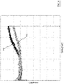
- a flow rate of the airflow exiting the de-fluff filter 218 remains substantially constant for longer periods during the operation of the laundry machine 100 even in the occurrence of large amounts of fluff collected in the de-fluff filter 218 , as can be appreciated in Figure 6 that is a chart showing air pressure as a function of time during operation of the laundry machine 100 according to an embodiment of the invention and of a laundry machine known in the art.
- a first air-pressure curve 605 is a measurement of the air pressure (measured in mmH 2 O) as a function of time during operation of a laundry machine 100 comprising the de-fluff filter 218 according to an embodiment of the present invention and a second air-pressure curve 610 is a measurement of air pressure as a function of time during the operation of a laundry machine known in the art.
- the first air-pressure curve 605 remains substantially constant for a longer extent of time than the second air-pressure curve 610. Moreover, the rise in pressure exhibited by the first air-pressure curve 605 is substantially linear and with a very low angular coefficient, while the rise in pressure exhibited by the second air-pressure curve 610 result to be steeper with a non-linear trend and reaches a maximum value (at the end of the operation) substantially higher than the maximum value reached by the first air-pressure curve 605 .
- a compressor (not shown) comprised in the heat pump may operate with a substantial constant number of round per minute, or with a limited variations of rounds per minute.
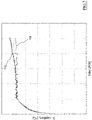
- a capillary temperature results to be lower during the operation of the laundry machine 100 as can be appreciated in Figure 7 that is a chart showing capillary temperature as a function of time during the operation of a laundry machine 100 according to an embodiment of the invention and of a laundry machine known in the art.
- a first temperature curve 705 is a measurement of temperature (measured in Celsius degrees) as a function of time during operation of a laundry machine 100 comprising the de-fluff filter 218 according to an embodiment of the present invention and a second temperature curve 610 is a measurement of temperature as a function of time during the operation of a laundry machine known in the art.
- first temperature curve 705 remains equal to or lower than the second temperature curve 710 during the whole considered time.
- first temperature curve 705, apart for limited variations, remains substantially constant once reached a steady value of temperature during the operation of the laundry machine 100, while the second curve 710 exhibits a substantially linear increase in temperature during the operation of the laundry machine after an initial steep increase.
- airflow diverters may be arranged for automatically swinging from a first position, in which the airflow is directed into a first portion of the de-fluff filter, to a second position, in which the airflow is directed into a second portion of the de-fluff filter, according to a quantity of fluff currently trapped in the de-fluff filter.
- the airflow diverter could be hinged to the bottom wall of the filter box in such a way to swing from the first position to the second position as above described. The movement of such diverters being caused by the airflow itself or by a driving device.
- a deformable airflow diverter (e.g., manufactured in a resilient material) may be arranged for having a rest configuration, in which the airflow is directed into a first portion of the de-fluff filter, and is arranged for shift to a deformed configuration, in which the airflow is directed into a second portion of the de-fluff filter, according to a quantity of fluff currently trapped in the de-fluff filter.
- the deformation of such diverter being caused by the airflow itself or by a deformation inducing device.
- the laundry machine 100 may operate also without the auxiliary de-fluff filter 221 and/or the septum 370 in their working positions, i.e. with only the filtering mesh of the second transversal sidewall 303d of the de-fluff filter 218 filtering the airflow coming from the laundry treatment chamber 105.
- auxiliary filter 221 and its housing may be omitted.
Landscapes
- Engineering & Computer Science (AREA)
- Textile Engineering (AREA)
- Detail Structures Of Washing Machines And Dryers (AREA)
Description
- The present invention relates to laundry treatment appliances or machines. In more detail, the present invention refers to appliances for drying laundry, both for domestic and professional use. More particularly, the present invention relates to a de-fluff filter.
- Drying and washing/drying laundry machines - which will be referred to simply as laundry machine in the following - typically comprise a casing substantially parallepiped-shaped. The casing accommodates a laundry treating chamber, comprising a drum, generally rotatable, apt to contain the laundry to be dried, in the case of a washing/drying laundry machine, the drum is rotatably contained in a tub. A front panel of the casing has a loading opening to access the treating chamber for loading/unloading the laundry, and a door is provided for closing the loading opening, particularly during the laundry machine operation.
- The casing also accommodates the electrical, electronic, mechanical, and hydraulic components necessary for the operation of the laundry machine. Particularly, laundry-drying capable machines features an air circuit (comprising, for example, fans, air ducts, a moisture condensing unit, a heating unit, etc.) adapted to heat air, blow it into the drum where it removes moisture from the laundry, suck out from the drum the moisturized air, de-moisturize the air and reiterate such actions thereby performing a laundry drying cycle.
- During a washing and/or drying process, the laundry under treatment typically loses lint particles or fluff. The fluff is generally light and tiny, thus it can be brought out from the drum by the hot drying air flowing therein and then into the air circuit.
- Once in the air circuit, the fluff is likely to accumulate therein, thereby possibly obstructing air ducts of the air circuit or negatively affecting the operation of one or more of its components (e.g., fluff may deposit on a fan, to the extent of possibly causing the latter to operate with a lower efficiency or completely stop it). In general, fluff accumulation has a detrimental effect on the laundry drying machine operation.
- Therefore de-fluff filters have been designed for the purpose of retaining the fluff so as to prevent it from damaging the laundry machine components. Nevertheless, the de-fluff filter needs to be periodically cleaned to avoid it to get clogged, event that may reduce the laundry machine efficiency or even cause a laundry drying machine malfunction, at least of the air circuit thereof. To this purpose, the de-fluff filter is usually removably accommodated in a filter seat within the air circuit, for example in a position located at the front of the casing in a top portion thereof, i.e. in positions that are easily reachable by a user.
- Notwithstanding the implementation of meticulous de-fluff filter maintenance, fluff may still amass within the de-fluff filter during the course of a single laundry drying machine operation in a quantity that may affect the efficiency of the laundry machine.
- Particularly, fluff trapped in the de-fluff filter may hinder the flow of air within the air circuit of the laundry drying machine. For example, trapped fluff may reduce a flow rate through the de-fluff filter, thus causing localized pressure peaks and drops in the air circuit and subsequent localized /or temperature rise along the air circuit.
-
EP 2 843 103 A1 discloses a laundry machine with a de-fluff filter, which comprises a filter box and a lid defining a hollow chamber within. A filtering mesh is arranged on an outlet portion of the box on a transversal sidewall. The lid comprises air guiding blades protruding from a lower side of the lid towards the inside of the filter box, subdividing the hollow chamber of the filter box in sub-chambers. The sub-chambers have a sectional area that increases along the drying air flow direction path, in such a way to distribute evenly the drying air flow inside the filter box for homogenously directing the drying air flow towards the filtering mesh. -
US 5,651,188 A discloses a lint storage system comprising a lint basket with one hollow chamber therein. The lower and side surfaces of the basket comprise outlet openings covered with filter elements, wherein the size of the outlet openings increases from the air inlet end of the basket to the outlet end of the basket. - It would be therefore desirable to increase the number of laundry drying processes performable between two subsequent de-fluff filter cleaning operations with a sufficient degree of energy efficiency. In particular, it would be desirable to achieve that goal limiting or even avoiding, the increase of the filter seat.
- The Applicant has tackled the problem of devising a laundry machine comprising a de-fluff filter arrangement capable to overcome, at least partly, the drawbacks of the prior art.
- The Applicant has devised a de-fluff filter that is easy to insert into, and to remove out of a corresponding housing, and which is able to ensure a substantially homogenous flow rate of air therethrough during the laundry machine operation.
- One aspect of the present invention proposes a laundry machine adapted to dry laundry by means of a flow of drying air is proposed. The laundry machine comprises: a casing; inside the casing, a laundry treating chamber adapted to contain the laundry to be dried; an air circuit in fluid communication with the laundry treating chamber through an inlet opening, and defining an air-path for the flow of drying air between said inlet and outlet openings; a filter housing for removably accommodating a de-fluff filter, said filter housing being provided in the air-path and being accessible through a housing aperture. The de-fluff filter is arranged for trapping fluff or lint particles carried by the flow of drying air crossing said de-fluff filter, the de-fluff filter comprises a filtering element and a hollow chamber which comprises an inlet aperture and an outlet portion. The de-fluff filter further comprises an airflow diverter which: divides the hollow chamber of the de-fluff filter in a first portion and a second portion, and diverts the flow of drying air entering the de-fluff filter towards the first portion of the hollow chamber or towards the second portion of the hollow chamber according to an amount of fluff currently trapped in the at least one filtering element.
- The airflow diverter comprises at least one filtering element for filtering the flow of drying air entering the first portion of the hollow chamber of the de-fluff filter thereby trapping fluff or lint particles.
- Preferred features of the present invention are set in the dependent claims.
- According to the invention, the majority of drying air flow entering the de-fluff filter is directed to the first portion of the hollow chamber in a first part of a drying process. The airflow diverter is arranged for diverting the flow of drying air entering the de-fluff filter from the first portion of the hollow chamber towards the second portion of the hollow chamber according to an amount of fluff currently trapped in first portion of the hollow chamber.
- In an embodiment of the invention, the first portion and the second portion of the hollow chamber define, for the flow of drying air, two paths causing a different amount of energy losses to the fluid portions entering the first and the second portion respectively.
- In an embodiment of the invention, the amount of energy losses caused by the first portion is lower than the amount of energy losses caused by the second portion.
- In an embodiment of the invention, during a laundry drying process, the progressive accumulation of fluff or lint particles in the first region of the hollow chamber increases the amount of energy losses to the fluid portion entering the first portion up to make such amount greater than the amount of energy losses caused by the second portion.
- In an embodiment of the invention, the airflow diverter traps fluff or lint particles at least up to a threshold amount that causes substantially the whole airflow to divert from the first region to the second region of the hollow chamber.
- In an embodiment of the invention, said threshold amount of fluff or lint particles is a function of at least one among: a size of the first region, a size of the hollow chamber, a size of the airflow diverter and a size of a filtering element provided in the airflow diverter or in the de-fluff filter.
- In an embodiment of the invention, the airflow diverter comprises a peripheral frame and at least one separating element, the peripheral frame and at least one separating element defining two or more filtering elements.
- In an embodiment of the invention, the peripheral frame is integral with the at least one separating element.
- In an embodiment of the invention, the peripheral frame and the at least one separating element comprise a first half and a second half, each half being symmetrical to the other and designed to couple with the other half along a longitudinal symmetry plane of the airflow diverter.
- In an embodiment of the invention, the airflow diverter is removably mounted in the hollow chamber of the de-fluff filter.
- In an embodiment of the invention, the airflow diverter further comprises at least one foot element arranged for coupling with the de-fluff.
- In an embodiment of the invention, the de-fluff filter further comprises at least one foot receptacle. Preferably, the at least one foot element is arranged for coupling with said at least one foot receptacle.
- In an embodiment of the invention, the de-fluff filter further comprises one or more retaining brackets for holding the airflow diverter in a working position within the hollow chamber.
- In an embodiment of the invention, the de-fluff filter further comprises a filter box and a lid hinged to the filter box for pivoting from an opening position to a closed position thereby selectively closing a top aperture of the filter box, the hollow chamber being defined by the filter box and by the lid in the closed position. Preferably, the airflow diverter is arranged for being flush both with the lid and with a bottom wall of the filter box opposite to the lid.
- In an embodiment of the invention, the lid comprises a plurality of lid ridges protruding towards the filter box once the lid is in the closed position. Preferably, the filter box comprises corresponding box ridges protruding towards the lid once the lid is in the closed position, the lid ridges being arranged for interspersing with the box ridges once the lid is in the closed position thereby forming a meandering path capable of hindering the passage of fluff.
- In an embodiment of the invention, the hollow chamber is delimited by a guiding wall and a sidewall, the airflow diverter being arranged therebetween so as to form with at least one of said guiding wall and sidewall a path having a convergent portion along the direction of the flow of air.
- In an embodiment of the invention, the airflow diverter is movable from a first position, in which the airflow is directed into a first portion of the de-fluff filter, to a second position, in which the airflow is directed into a second portion of the de-fluff filter.
- In an embodiment of the invention, the airflow diverter is deformable between a rest configuration, in which the airflow is directed into a first portion of the de-fluff filter, and a deformed configuration, in which the airflow is directed into a second portion of the de-fluff filter.
- These, and others, features and advantages of the solution according to the present invention will be better understood with reference to the following detailed description of some embodiments thereof, provided for illustrative and not restrictive purposes, to be read in conjunction with the attached drawings. In this regard, it is expressly intended that the drawings are not necessarily to scale and that, unless specified otherwise, they simply aim to conceptually illustrate the structures and procedures. In particular:
-
Figure 1 is a perspective view of a laundry machine according to an embodiment of the present invention; -
Figure 2A is a perspective view of the laundry machine ofFigure 1 , showing a top thereof in exploded view; -
Figure 2B is a perspective view of a base element of the top of the laundry machine according to an embodiment of the present invention; -
Figure 3A is a perspective view of a de-fluff filter according to an embodiment of the present invention; -
Figure 3B is a perspective view of a de-fluff filter according to an embodiment of the present invention with its lid; -
Figure 3C is a top view of a de-fluff filter according to an embodiment of the present invention shown with a lid and an airflow septum removed; -
Figure 3D is a cross-sectional top view along section plane IIID of the de-fluff filter ofFigure 3A according to an embodiment of the present invention shown with a lid removed and the airflow septum inserted, -
Figure 4A is a cross-sectional front view along section plane IVA of a de-fluff filter according to an embodiment of the present invention; -
Figure 4B and4C are a close up views ofFigure 4A showing the coupling between a filter box and a lid of a de-fluff filter according to an embodiment of the present invention; -
Figures 5A and 5B are a side view and a top view, respectively, of an airflow septum according to an embodiment of the invention; -
Figure 6 is a chart showing air pressure as a function of time during operation of a laundry machine according to an embodiment of the invention and of a laundry machine known in the art, and -
Figure 7 is a chart showing capillary temperature as a function of time during the operation of a laundry machine according to an embodiment of the invention and of a laundry machine known in the art. - With reference to the drawings,
Figure 1 is a perspective view of a laundry machine, globally denoted as 100, according to an embodiment of the present invention. - The
laundry machine 100 comprises alaundry treatment chamber 105 for accommodating the items to be dried or washed and dried, such as clothes, garments, linen, and similar laundry items. Preferably, thelaundry treatment chamber 105 includes a drum (not shown) rotatably mounted inside a machine cabinet orcasing 110, and in case thelaundry machine 100 is a washing/drying laundry machine the drum is arranged within a tub (not shown) housed in themachine casing 110. - The
casing 110 generally accommodates all the electrical, electronic, mechanical, and hydraulic components necessary for the operation of the laundry machine. Thecasing 110 has generically a parallelepiped shape, with afront wall 115, two side walls 120 (only one visible inFigure 1 ), a rear wall (not visible), a basement and a top element, or simply top 125. Thefront wall 115 is provided with an opening for accessing the drum and with an associateddoor 117 for closing the opening. In the upper part of thefront wall 115, amachine control panel 130 is located, and, aside thecontrol panel 130, adrawer 135 is provided, which is part of a washing treatment products dispensing arrangement, for loading laundry washing treatment products like detergents and softeners. The top 125 closes thecasing 110 from above, and defines a worktop. - In one embodiment of the invention, a de-fluff filter (aesthetic)
cover 140 is exposed on thecontrol panel 130 on thefront wall 115, e.g. above thedrawer 135, and flushing therewith. - Preferably, the
de-fluff filter cover 140 may comprise apushbutton portion 145 for actuating a release of thede-fluff filter 218 from its working position (as described in the following). - Reference is now made to
Figures 2A and2B , which are a perspective views of thelaundry machine 100 with its top 125 in exploded view and a perspective view of abase element 205 of the top 125 with some parts removed. - In one embodiment of the invention, the top 125 integrates part of an air circuit adapted to circulate drying air across the
laundry treating chamber 105 for drying the laundry stored therein (as described below). - The top 125 comprises the
base element 205, which has aninlet opening 210 and anoutlet opening 215, theinlet opening 210 being in fluid communication with thelaundry treatment chamber 105 through a chamber outlet, theoutlet opening 215 being in fluid communication with afan arrangement 216. - The
fan arrangement 216 comprises a fan and a corresponding fan duct, the fan produces the drying airflow inside the air circuit by sucking drying air from theoutlet opening 215 and blowing the drying air into thelaundry treatment chamber 105, theoutlet opening 215 and thelaundry treatment chamber 105 being both fluidly connected to thefan arrangement 216. - In the region of the
base element 205, preferably near the front-left corner thereof, afilter housing 217 is provided. - The
filter housing 217 is suitable to house a de-fluff filter 218 (described in greater detail below). - Preferably, the
filter housing 217 has roughly a right trapezoid outline in plan view (e.g., similar to a grand piano), with ashorter sidewall 217a (corresponding to a lesser base of the right trapezoid) in fluid communication with the chamber outlet by means of theinlet opening 210, and alarger sidewall 217b (opposite to theshorter sidewall 217a, and corresponding to a greater base of the right trapezoid) that has ahousing aperture 219 opened on themachine front wall 115 preferably in aseparating wall 205a of thebase element 205. - Preferably, the
housing aperture 219 is provided in aseparating wall 205a provided adjacent to thecontrol panel 130, even more preferably above thedrawer 135 for allowing the insertion of thede-fluff filter 218. - Moreover, the
filter housing 217 comprises aright sidewall 217c substantially corresponding to a portion of a lateral sidewall of thebase element 205 of the top 125 (and corresponding to the right leg of the right trapezoid) and a transversal openedside 217d, preferably inclined (opposite to theright sidewall 217c and corresponding to the inclined leg of the right trapezoid). - In one embodiment of the present invention, the
inlet opening 210 is fluidly connected to anadapter element 212, which is provided to fluidly connect the inlet opening 210 with thefilter housing 217 and the de-fluff filter 218 (when inserted in the filter housing 217). - Preferably, but not limitatively, the
adapter element 212 may be a parallelepiped-shape element adapted to be coupled with thebase element 205. Theadapter element 212 further comprises conical or cylindrical passage(s) having two opposite apertures to fluidly connect the inlet opening 210 with thede-fluff filter 218. - The
adapter element 212 may be made of any suitable material, e.g. a polymeric material, and is coupled with thebase element 205 by means of any suitable coupling arrangement, e.g. by tightly fitting (preferably in an airtight manner) a rear portion of the filter housing 217 (adjacent to theshorter sidewall 217a). - In a preferred embodiment of the invention, the aperture facing the
filter housing 217 of theadapter element 212 is surrounded by agasket element 212a which protrudes towards the inside of thefilter housing 217. - In alternative embodiments of the present invention in which the
adapter element 212 is not provided, and an alternative gasket element may be directly provided around the inlet opening 210 for directly coupling with thede-fluff filter 218. - In one embodiment of the present invention, the transversal opened
side 217d comprises aframe 220 that defines a plurality ofside windows 220a separated one from the other by separating elements, such as forexample mullion elements 220b, preferably prism-shaped. Preferably, at theframe 220 housing grooves (not visible inFigures 2A and2B ) adapted to house anauxiliary filter 221 are provided. - Advantageously, a plurality of
flap elements 222 may be provided. Theflap elements 222 protrude from theframe 220 opposite to thefilter housing 217 in order to direct the drying airflow exiting the transversal openedside 217d towards the rest of the air circuit defined in the top 125. - In the central region of the
base element 205, there is accommodated a first heat-exchanging unit, such as amoisture condensing element 225, for example comprising an evaporator of a heat pump apparatus. - The
moisture condensing element 225 is adjacent to the transversal openedside 217d, and thus the external surface of the former is in fluid communication with the latter. - Next to the
moisture condensing element 225, opposite to thefilter housing 217, there is provided a second heat-exchanging unit, such as a dryingair heating element 230, for example comprising a condenser of the heat pump apparatus. - The
moisture condensing element 225 has the function of dehydrating the drying air, by cooling it down; the dryingair heating element 230 has instead the function of heating the dehydrated drying air. - A compressor (not shown) for the heat pump may be attached to the
base element 205 in correspondence of the front-right corner thereof, the body of the compressor protruding from below thebase element 205. - In an alternative embodiment, the compressor may be located in the bottom of the
casing 110, attached to the basement of thelaundry machine 100, and be fluidly connected to themoisture condensing element 225 accommodated in the top 125 by means of flexible pipes that preferably run along a rear corner of thecasing 110 or along thelaundry treatment chamber 105 of thelaundry machine 100. - In a different embodiment of the present invention, the
laundry machine 100 may comprise an air-air or an air-water heat exchanger apparatus and an electric heater instead of the heat pump apparatus. - The
base element 205 of the top 125 is covered by aninner panel 235, that covers essentially themoisture condensing element 225, the dryingair heating element 230 and thede-fluff filter 218. - The top 125 is completed by an outer (aesthetic)
panel 240. - The
base element 205 and theinner panel 235 define an air-path that conveys the moisture-laden air coming from the laundry treatment chamber 105 (through the inlet opening 210) towards thede-fluff filter 218, preventing the moisture-laden air from entering directly themoisture condensing element 225 or the drying air heating element 230 (i.e., before being filtered by the de-fluff filter 217), and then the drying airflow follows the air-path from thede-fluff filter 218 to theheating element 230, passing through themoisture condensing element 225, and eventually reaching theoutlet opening 215. - Preferably, the top 125, once assembled, forms a unit that is ready to be mounted to the
casing 110, simply by placing it in the correct alignment, so that theopenings fan arrangement 216, respectively, thus realizing a closed air circuit comprising thelaundry treatment chamber 105 and the air-path defined by thebase element 205 and theinner panel 235, and thefan arrangement 216. The top 125 may then be secured to thecasing 110 by conventional means (e.g., by means of gluing, screwing or other connecting/fastening means). - When the
laundry machine 100 is operated in dryer mode (i.e., for drying items stored in the drum), drying air (i.e., warm and dry air) is typically caused to flow through thedrum 105 inside thelaundry treating chamber 105, where the items to be dried are contained. - The drying air binds to moisture particles from the laundry and/or dispersed within the
laundry treating chamber 105 and carries them away. The drying air may also carry away fluff (e.g., comprised in and/or generated from the laundry during laundry treating processes) from the laundry together with moisture particles. - After exiting the drum through the chamber outlet, the flow of now moisture-laden drying air passes through the
de-fluff filter 218 where substantially any fluff carried by the drying airflow together with moisture particles is caught and remains trapped. - Instead, the moisture-laden drying air is conveyed towards the
moisture condensing element 225, where the moisture-laden drying air is at least partially dried, i.e. dehydrated, and such dehydrated drying airflow is then heated by theair heating element 230 through which the drying airflows, which heats the drying air up to a drying temperature (e.g., set by a user through thecontrol panel 130 via the selection of a drying program). - Then the drying air is sucked by the fan through the fan intake and is caused to pass again through the
drum 105 drying the laundry therein stored and then repeating the cycle just described. - Considering now
Figures 3A to 3D , they are views of thede-fluff filter 218 according to embodiments of the present invention shown with and without alid 306. - It should be noted that the
de-fluff filter 218 is shown with also theaesthetic cover 140 removed in the following figures. - The
de-fluff filter 218 is designed to be inserted inside thefilter housing 217 preferably through thehousing aperture 219 exposed on thefront wall 115. Preferably, thede-fluff filter 218 is designed such as an extractable drawer. - The
de-fluff filter 218 comprises afilter box 303, a cover element, such as for example alid 306, and in addition it may preferably comprise a closing element, such a swingingbulkhead 309, an ejection device (not shown), and a locking element (not shown). - The
filter box 303 has a parallelepiped shape, preferably with a roughly rectangular trapezoid base. For example, thefilter box 303 of thefilter housing 217 may have a shape similar to that of a grand piano, with arear sidewall 303a, afront sidewall 303b, a firsttransversal sidewall 303c, a secondtransversal sidewall 303d, preferably curved, and abottom wall 303e. The sidewalls 303a, 303b, 303c, 303d delimit a top aperture 303t of thefilter box 303. Thefilter box 303 may be made in any suitable material, such as for example a suitable polymer (e.g., Polypropylene PP). - Preferably (as can be appreciated in
Figure 2B ), thefilter box 303 is designed in such a way that, once thede-fluff filter 218 is inserted into thefilter housing 217, the former substantially tightly fits the latter. Even more preferably, the sidewalls 303a and 303c are adapted to substantially flank the sidewalls 217a and 217c, respectively, of thefilter housing 217 and may contact them, while thefront sidewall 303b substantially closes thehousing aperture 219 and the secondtransversal sidewall 303d faces the transversal openedside 217d of thefilter housing 217, preferably remaining separated therefrom. - Preferably, the
filter box 303 is designed in such a way that its secondtransversal sidewall 303d remains spaced apart from the transversal openedside 217d of thefilter housing 217, thus defining a gap between the secondtransversal sidewall 303d and the transversal openedside 217d. Within the gap a housing for receiving, preferably in a sliding manner, the auxiliary filter 221 (the housing being not detailed in the Figures). - The second
transversal sidewall 303d operates substantially as a filtering portion and as an outlet portion of thede-fluff filter 218. The secondtransversal sidewall 303d comprises aframe 318 that encloses a plurality offiltering windows 318a separated from each other by separating elements, such as for examplebox mullion elements 318b, preferably parallelepiped shaped. Thebox mullion elements 318b extend from a lower portion of the frame 318 (at thebottom wall 303b) of thefilter box 303 up to a higher portion of the frame 318 (at the top aperture 303t). Advantageously, thebox mullion elements 318b are designed to align with themullion elements 220b of the transversal openedside 217d (once thede-fluff filter 218 is inserted into the filter housing 217), in such a way to not to hinder the drying airflow. - The
filter box 303 further comprises a filtering element, such as for example a filtering mesh (not shown in the figures for simplicity). - The filtering mesh is preferably substantially rectangular in shape and is sized with a length and a height substantially equal to a length and a height of the second
transversal sidewall 303d. - Preferably, the filtering mesh is coupled with the second
transversal sidewall 303d covering the apertures of thefiltering windows 318a in such a way to filter the drying airflow passing therethrough (as will be described in greater detail in the following). - The filtering mesh is preferably coupled with the second
transversal sidewall 303d on an internal face thereof (i.e., facing the inside of the filter box 303). - The filtering mesh may be made in any suitable material, such as for example a suitable polymer (e.g., Polyethersulfone or "PES") that may be over-injected onto the internal face of the second
transversal sidewall 303d. - Alternatively, the filtering mesh may be attached to the
frame 318 of the secondtransversal sidewall 303d in any other suitable manner (e.g., by gluing together the filtering mesh and the secondtransversal sidewall 303d) or, conversely, may be removably coupled with the frame 318 (e.g., by providing suitable snap-fit engage elements). Alternatively, a plurality of smaller filtering meshes may be provided each one adapted to be coupled with arespective filtering window 318a. - It should be noted that the
mullion elements 318b, along enhancing the structural strength of theframe 318 also enhance a robustness of the filtering mesh preventing deformation of the filtering mesh that the airflow may provoke, e.g. a bending of the central portion of the filtering mesh in the direction of the flow of air that could cause a concentration of trapped fluff in such bent central portion. - The
filter box 303 preferably also comprises acover support 324 attached to (or, alternatively, formed integral with) thefront sidewall 303b. - The
cover support 324 is designed to protrude outwards from theaperture 219 in thelarger sidewall 217b in order to support thede-fluff filter cover 140. - For example, the
de-fluff filter cover 140 may be coupled with thecover support 324 by means of one or more snap-fit elements (not shown), each fitting a corresponding coupling element, such asholes 324a, provided on thecover support element 324. - Preferably, the
cover support 324 comprises atab 327 protruding substantially transversal to thefront sidewall 303b and extending towards therear sidewall 303a on an end of thecover support 324. - In other embodiments according to the present invention, a tab may be placed in a different position and/or more than just a tab may be provided.
- The
tab 327 is advantageously provided in order to prevent incorrect insertions of thede-fluff filter 218 into thefilter housing 217. - For example, the
de-fluff filter 218 is designed to inserted in thefilter housing 217 only if thetab 327 is inserted inside a tab slot 230 (visible inFigure 2B ) that is provided on the separatingwall 205a of thebase element 205, which substantially separates thecontrol panel 130 from the inner portion of the top 125, preferably in a position close to theaperture 219. - In different embodiments of the present invention, the
cover support 324, thefront sidewall 303b and/or thede-fluff filter cover 140 may be either formed as different elements that can be engaged one another in any suitable known manner, or as a one-piece element. - In alternative embodiments of the present invention, an alternative cover element may be provided featuring a grasping element (such as for example a handle).
- The
rear sidewall 303a of thefilter box 303 comprises aninlet aperture 330 which is adapted to receive the drying airflow coming from thelaundry treatment chamber 105 through the inlet opening 210 in theshorter sidewall 217a. - Preferably the outlet portion, i.e. the second
transversal sidewall 303d, has a greater extension than theinlet aperture 330, such that the filtering mesh arranged on theoutlet portion 303d may have a wide extension. - Preferably, the
rear sidewall 303a is also provided with a protrudingframe 333 that surrounds theinlet aperture 330 and protrudes from a border of thefilter box 303 surrounding theinlet aperture 330 towards the outside of thefilter box 303. The protrudingframe 333 is adapted to engage with thegasket element 212a of theadapter element 212 preferably in an airtight manner (thus fluidly connecting thede-fluff filter 218 with inlet opening 210). - Advantageously, the swinging
bulkhead 309 is provided at theinlet aperture 330. The swingingbulkhead 309 has a shape, e.g. substantially rectangular, adapted to close, preferably seal, theinlet aperture 330. The swingingbulkhead 309 is designed to have a weight such that a kinetic force of the drying airflow from thelaundry treatment chamber 105 is able to swing the bulkhead towards the inside of the filter box 303 (thus, clearing the inlet aperture 330). The swingingbulkhead 309 may be made in any suitable material, e.g. a polymer. - Preferably, the swinging
bulkhead 309 is hinged to the firsttransversal sidewall 303c and to the secondtransversal sidewall 303d close to therear sidewall 303a. For example, the swingingbulkhead 309 may be provided with two protruding pins 309a on opposite shortest sides (at top corners thereof), which are adapted to be inserted into two matching rear bores 336, a first one provided in the firsttransversal sidewall 303c and a second one provided in the secondtransversal sidewall 303d. - Preferably, at the
inlet aperture 330 an abutment element (not shown) is provided. Advantageously, the abutment element is adapted to prevent the swingingbulkhead 309 from swinging towards the outside of the filter box 303 (i.e., the swingingbulkhead 309 is allowed to swing only towards the inside of the filter box 303). - Thanks to the swinging
bulkhead 309 and the abutment element it is possible to prevent, or substantially reducing, any spurious flow of air from thede-fluff filter 218 towards the inlet opening 210 (i.e., opposite to the direction desired for the flow of drying air). - Preferably, in the
bottom wall 303e a niche 339 is formed (as can be seen in theFigure 3D ). The niche 339 is adapted to operatively house a blocking/ejecting device (not shown in the drawings) that allows both (mechanincally) blocking and ejecting thede-fluff filter 218 from itshousing 217. - Advantageously, thanks to the blocking/ejecting device a user can easily unlock the
de-fluff filter 218 from itshousing 217 simply by pressing thepushbutton portion 145 of theaesthetic cover 140 of thede-fluff filter 218. - Even more preferably, the blocking/ejecting device allows the
de-fluff filter 218 to be at least slightly ejected from thefilter housing 217 so as to be easily grasped by a user. - In an inner portion of the
filter box 303 a guidingwall 354 may be preferably provided in order to guide the drying airflow from theinlet aperture 330 to the secondtransversal sidewall 303d. - For example, the guiding
wall 354 may be a curved wall connecting the firsttransversal sidewall 303c with an end of the secondtransversal sidewall 303d adjacent to thefront sidewall 303b. - Generally, the guiding
wall 354 is designed in such a way to provide the best fluid-dynamic behaviour for the drying airflow inside the filter box 303 (e.g., adapted to effectively direct the drying airflow homogenously towards the whole secondtransversal sidewall 303d generating the lowest turbulence in the drying airflow as possible). - Even more preferably, the guiding
wall 354 may comprise a bent (or slanted)portion 354a at the intersection with thebottom wall 303e of thefilter box 303. Thebent portion 354a of the guidingwall 354 is designed for provide the best fluid-dynamic behaviour for the drying airflow inside the filter box 303 (as generally the whole the guiding wall 354) and also avoids fluff stockpiling facilitated by sharp angles (e.g., substantially at 90°) at the intersection between the guidingwall 354 and thebottom wall 303e. - The top aperture 303t of the
filter box 303 is closed by thelid 306, preferably in an airtight manner. Thelid 306 may be preferably made of a suitable polymer. - More preferably the
lid 306 is made of a bi-component plastic using over-injection technology. For example, alid frame 357, preferably comprisingperipheral portion 357a and internal (reinforcing)ribs 357b, may be made of Acrylonitrile Butadiene Styrene (ABS). Conversely,transparent panes 360 provided enclosed by thelid frame 357, preferably with eachtransparent pane 360 provided in position delimited byribs 357b and/or theperipheral portion 357a of thelid frame 357, may be made of Polycarbonate (PC). Thetransparent panes 360 allow a user to verify the presence, and the quantity, of fluff trapped inside thefilter box 303 without the need of opening it. - As can be best appreciated from
Figures 4A to 4C , on thelid frame 357, a sealingborder 357c is preferably provided. - The sealing
border 357c protrudes from thelid frame 357 from a lower side thereof (i.e., towards the inside of thefilter box 303 when thelid 306 closes the top aperture 303t of the latter), and preferably along positions of thelid frame 357 that corresponds to therear sidewall 303a, the secondtransversal sidewall 303d, the guidingwall 354 and a portion of the firsttransversal sidewall 303c of thefilter box 303. - For example, the sealing
border 357c comprises a plurality oflid ridges 363 protruding downwards (i.e., towards thefilter box 303 once thelid 306 is coupled therewith). - Correspondingly, on a topmost portion of the
rear sidewall 303a, the secondtransversal sidewall 303d, the guidingwall 354 and a portion of the firsttransversal sidewall 303c of thefilter box 303 corresponding box ridges 367. The box ridges 367 protrude upwards (i.e., towards thelid 306 once thefilter box 303 is coupled therewith). - The
lid ridges 363 and the box ridges 367 are arranged for intersperse once thelid 306 is coupled with the filter box 303t in the closed position. - Thanks to the
lid ridges 363 and the box ridges 367, the sealingborder 357c and the top portion of the sidewalls 303a, 303c, and 303d are adapted to hinder the passage to fluff by forming a meandering path (or 'maze' as can be appreciated inFigures 4A to 4C ). - In summary, the sealing
border 357c is designed to substantially seal the top aperture 303t of thefilter box 303, when thelid 306 is in a closed position, thus allowing air entering and/or exiting ahollow chamber 361 within the de-fluff filter 218 (i.e., defined by thefilter box 303 and thelid 306 in closed position in which trapped fluff remains confined) only through theinlet aperture 330 and thefiltering windows 318a in the secondtransversal sidewall 303d. - In an embodiment of the invention, the sealing
border 357c and the top portion of the sidewalls 303a, 303c, and 303d may be designed in such a way to couple together by substantially a snap-fit engagement. - In a further embodiment of the present invention, as an alternative or an addition, the sealing
border 357c may also be provided with a gasket and/or thelid ridges 363 and the box ridges 367 may be formed in a resilient material (e.g., a rubber-like material which may be, e.g., overmoulded on the material of the filter box 303) in order to obtain an improved airtight coupling with thefilter box 303. - In order to allow a user easily opening (i.e., de-couple) the
lid 306 from thefilter box 303, one or more grasping portions may be provided, such as for example one ormore opening flaps 357d, preferably at ends of theperipheral portion 357a of thelid frame 357 corresponding to the firsttransversal sidewall 303c and the secondtransversal sidewall 303d in the proximity of therear sidewall 303a of thefilter box 303. - In order to be pivotally coupled with the
filter box 303, thelid 306 comprises a couple ofhinges 366, preferably protruding substantially at opposite ends of a front side of the lid 306 (i.e., corresponding to thefront sidewall 303b of the filter box 303). - Each
hinge 366 protrudes from thelid frame 357 transversally thereto and has apin 366a in its turn protruding from the center of a flat portion 366b transversally thereto, with the flat portion 366b that is preferably substantially circular. - Each
pin 366a is adapted to engage a matching front bore 369 provided on the firsttransversal sidewall 303c and on the secondtransversal sidewall 303d in a location adjacent to thefront sidewall 303b. - According to the present invention, the
de-fluff filter 218 further comprises an airflow diverter. - The airflow diverter is arranged to divert, at least partly, the flow of air within the
hollow chamber 361 defined within thefilter box 303 closed by thelid 306 during thelaundry machine 100 operation. - Even more preferably, the airflow diverter is arranged for dynamically diverting the airflow within the
filter box 218. - According to the invention, the airflow diverter is arranged for diverting the airflow within the
filter box 218 according to a quantity of fluff trapped therein. - According to an embodiment of the invention, the airflow diverter comprises a
septum 370, which is adapted to be coupled with thefilter box 218. - Preferably, the
septum 370 is designed to be coupled with thefilter box 303, as can be seen inFigures 3B ,3D and4A . - The
septum 370, as can be appreciated inFigures 5A and 5B (which are a side view and a top view thereof, respectively), has substantially a rectangular shape. - The
septum 370 comprises aperipheral frame 370a that defines a plurality (e.g., five in the example of the figures) ofseptum filtering windows 370b together with corresponding separating elements, such as for example (septum)mullion elements 370c, which separate eachseptum filtering window 370b from adjacentseptum filtering windows 370b. - Preferably, the
septum mullion elements 370c are integral with theperipheral frame 370a. - In one embodiment of the invention, the structure formed by the
peripheral frame 370a and themullion elements 370c comprises two halves, i.e. afirst structure half 375a and asecond structure half 375b. - Preferably, each structure halves 375a and 375b are symmetrical one to the other, and each
structure half septum 370. - For example, a first side of each
structure half septum 370 and a second side is designed to couple (e.g., by snap-fit, bayonet mounting, through the use of fastening/clamping means, etc.) with a second side of theother structure half structure halves septum 370. - The
septum 370 further comprises a filtering element, such as for example a septum filtering mesh (not shown in the figures for simplicity). - The septum filtering mesh is preferably substantially rectangular in shape and is sized with a length and a height substantially equal to a length and a height of the
septum 370. - Preferably, the septum filtering mesh is coupled with the
peripheral frame 370a and themullion elements 370c in order to being exposed at theseptum filtering windows 370b. - For example, the filtering mesh is suited to be inserted between the
structure halves septum 370 and being maintained in a working position once thestructure halves - The
septum 370 further comprisesfeet elements septum 370 in a working position within thede-fluff filter 218. - In one embodiment of the invention, each
foot element peripheral frame 370a and transversally therethrough (e.g., with eachstructure half - Preferably, each
foot element respective mullion element 370c of theseptum 370. - The
feet elements corresponding feet receptacles bottom wall 303e. - For example, each
foot receptacle foot element feet receptacles feet elements feet receptacles feet elements - In alternative or in addition, as can be appreciated in
Figure 4A eachfoot receptacle peg element 405 protruding from thebottom wall 303e of thefilter box 303. Correspondingly, eachfoot element peg receptacle 410 arranged for receiving thepeg element 405. - In one embodiment of the invention, the
peg element 405 is arranged for snap-fitting with thepeg receptacle 410. - Preferably, a pair of (terminal) retaining
brackets filter box 303 for maintaining theseptum 370 in its working position. - In one embodiment of the invention, the retaining
brackets bottom wall 303e of thefilter box 303 towards the top aperture 303t. - Each retaining
bracket 390a is preferably arranged for removably receiving a free end of theseptum 370 in such a way to prevent excessive oscillations thereof during the operation of thelaundry machine 100. - For example, the retaining
brackets septum 370. - Preferably, the
septum 370 is coupled with thefilter box 303 by inserting the opposite ends of theseptum 370 in concave spaces of the retainingbrackets septum 370 towards thebottom wall 303e of thefilter box 303 until thefeet elements feet receptacles - Once the
septum 370 is in its working position inside thefilter box 303 the inner space delimited by the filter box 303 (and thus also thehollow chamber 361 defined within thefilter box 303 closed by the lid 306) results substantially subdivided in twodifferent regions - Preferably, the
septum 370 is designed for substantially being flush with thebottom wall 303e of thefilter box 303 and for reaching thelid 306, preferably contacting the latter, once thelid 306 is in its closed position (as can be appreciated inFigure 4A ). - According to the invention, during operation of the
laundry machine 100, theseptum 370 is arranged for diverting the flow of air from afirst region 395a to asecond region 395b of the twodifferent regions septum 370 is arranged for diverting the flow of air from thefirst region 395a to thesecond region 395b in a substantially automatic manner. Theseptum 370 diverts the airflow from thefirst region 395a to thesecond region 395b trigger by an amount of fluff collected within thehollow chamber 361 of thede-fluff filter 218 during the operation thereof. - In the exemplary embodiment at issue, initially the airflow carrying moisture and fluff accessing the
hollow chamber 361 of thede-fluff filter 218 through theinlet aperture 330 and is mainly driven into thefirst region 395a by the shape of the hollow chamber 361 (thanks to the shape of the guiding wall 354) of thede-fluff filter 218. - Preferably, the
septum 370 is arranged inside thehollow chamber 361 of thede-fluff filter 218 in such a way to define, together with the guidingsidewall 354, thefirst region 395a having a decreasing transversal section along the direction defined by the flow of air (i.e., substantially from theinlet aperture 330 towards thefront sidewall 303b). - In other words, the
septum 370 together with thede-fluff filter 218 defines a path having at least one convergent portion along the direction of the flow of air. Advantageously, flow of air is guided towards an end of thefirst region 395a, i.e. at the intersection between theseptum 370 and the guidingwall 354, and then crosses the septum filtering windows 370b.Therefore, substantially the whole (or a majority of the) airflow crossing thede-fluff filter 218 is initially filtered by theseptum filtering windows 370b of theseptum 370. Accordingly, the fluff is substantially mainly confined in thefirst region 395a, while the airflows reachessecond region 395b beyond theseptum 370 and the leaves thehollow chamber 361 of thede-fluff filter 218 through the secondtransversal sidewall 303d. - During the proceeding of the operation of the
laundry machine 100 fluff accumulates more and more in thefirst region 395a and, accordingly, a flow rate through theseptum filtering windows 370b of theseptum 370 progressively reduces. - In the considered embodiment, the reduction of the flow rate through the
septum filtering windows 370b is due to accumulation of fluff at theseptum filtering windows 370b of theseptum 370 pushed by the airflow thereagainst. - Therefore, the airflow entering the
hollow chamber 361 of thede-fluff filter 218 is progressively diverted from thefirst region 395a to thesecond region 395b as the flow rate through theseptum filtering windows 370b of theseptum 370 progressively drops. - The accumulation of fluff at the
septum filtering windows 370b of theseptum 370 may reduce the flow rate through theseptum 370 to the point that substantially all the airflow is diverted from thefirst region 395a to thesecond region 395b of thehollow chamber 361. - It should be noted that a threshold amount of fluff that provokes the diversion of the airflow is a function of the size of the
de-fluff filter 218, of thefirst region 395a of thehollow chamber 361, of theseptum 370 and of theseptum filtering windows 318a. - The fluff in the airflow diverted for entering directly in the
second region 395b is filtered by theseptum filtering windows 318a of the secondtransversal sidewall 303d before exiting thede-fluff filter 218. - It should be noted that the
filtering windows 318a are substantially free of fluff at this point of the drying process and thus ensure an unreduced flow rate of the airflow therethrough. - For example, in an initial phase of the
laundry machine 100 operation the flow of air is mainly filtered by theseptum filtering window 370b closer to the guiding wall 354 (i.e., the farthest from the inlet aperture 330) which, as the process thelaundry machine 100 operation, is firstly clogged by fluff filtered from the flow of air crossing theseptum 370. - The flow of air is progressively diverted from the
septum filtering window 370b closer to the guidingwall 354 to theseptum filtering window 370b adjacent thereto, and so on until all theseptum filtering windows 370b are substantially clogged (i.e., the flowrate of air flowing through eachseptum filtering window 370b is substantially reduced by the trapped fluff). - Once all the
septum filtering windows 370b of theseptum 370 are substantially clogged causes the air flow to be diverted to thesecond region 395b of thehollow chamber 361 where theunclogged filtering windows 318a of the secondtransversal sidewall 303d ensure an higher flowrate. - In other words, the
septum 370 divides thehollow chamber 361 in two regions, i.e. thefirst region 395a and thesecond region 395b, which define, for the flow of drying air, two paths causing a different amount of pressure drops, and accordingly energy losses (e.g., due to friction), to the portions of fluid (e.g. moisture and fluff-laden air) travelling through thefirst region 395a and thesecond region 395b. - Preferably, the flow of air inside the
de-fluff filter 218 follows a path through thefirst region 395a or through thesecond region 395b of thehollow chamber 361 which currently offers the lowest pressure drop, or the lowest energy losses. Particularly, initially the amount of energy losses caused by thefirst portion 395a of thehollow chamber 361 to the airflow is lower than the amount of energy losses caused by thesecond portion 395b thereto in an initial phase of thelaundry machine 100 operation (i.e., when theseptum filtering windows 370b are unclogged). - Successively, as the
septum filtering windows 370b progressively clog, the energy losses along a path of the flow of air through thefirst region 395a of the hollow chamber start to rise until a path for the flow of air through thesecond region 395b result to provoke lower energy losses to the airflow than the path of the flow of air through thefirst region 395a. - Thanks to the
septum 370 of thede-fluff filter 218 according to an embodiment of the present invention, a flow rate of the airflow exiting thede-fluff filter 218 remains substantially constant for longer periods during the operation of thelaundry machine 100 even in the occurrence of large amounts of fluff collected in thede-fluff filter 218, as can be appreciated inFigure 6 that is a chart showing air pressure as a function of time during operation of thelaundry machine 100 according to an embodiment of the invention and of a laundry machine known in the art. - In detail, a first air-
pressure curve 605 is a measurement of the air pressure (measured in mmH2O) as a function of time during operation of alaundry machine 100 comprising thede-fluff filter 218 according to an embodiment of the present invention and a second air-pressure curve 610 is a measurement of air pressure as a function of time during the operation of a laundry machine known in the art. - It should be noted that the first air-
pressure curve 605 remains substantially constant for a longer extent of time than the second air-pressure curve 610. Moreover, the rise in pressure exhibited by the first air-pressure curve 605 is substantially linear and with a very low angular coefficient, while the rise in pressure exhibited by the second air-pressure curve 610 result to be steeper with a non-linear trend and reaches a maximum value (at the end of the operation) substantially higher than the maximum value reached by the first air-pressure curve 605. - This ensures a more stable air pressure in the whole air circuit of the
laundry machine 100 that entails high efficiency of the laundry machine operation. - Thanks to the substantially stable pressure during the operation of the
laundry machine 100 ensured by thede-fluff filter 218 according to embodiments of the present invention lead to a substantially homogeneous operation of the heat pump of the air circuit of thelaundry machine 100. - For example, a compressor (not shown) comprised in the heat pump may operate with a substantial constant number of round per minute, or with a limited variations of rounds per minute.
- Moreover, a capillary temperature results to be lower during the operation of the
laundry machine 100 as can be appreciated inFigure 7 that is a chart showing capillary temperature as a function of time during the operation of alaundry machine 100 according to an embodiment of the invention and of a laundry machine known in the art. - In detail, a
first temperature curve 705 is a measurement of temperature (measured in Celsius degrees) as a function of time during operation of alaundry machine 100 comprising thede-fluff filter 218 according to an embodiment of the present invention and asecond temperature curve 610 is a measurement of temperature as a function of time during the operation of a laundry machine known in the art. - It should be noted that the
first temperature curve 705 remains equal to or lower than the second temperature curve710 during the whole considered time. In addition, thefirst temperature curve 705, apart for limited variations, remains substantially constant once reached a steady value of temperature during the operation of thelaundry machine 100, while thesecond curve 710 exhibits a substantially linear increase in temperature during the operation of the laundry machine after an initial steep increase. - In other embodiments of the invention (not shown), different airflow diverters may be implemented.
- For example, airflow diverters may be arranged for automatically swinging from a first position, in which the airflow is directed into a first portion of the de-fluff filter, to a second position, in which the airflow is directed into a second portion of the de-fluff filter, according to a quantity of fluff currently trapped in the de-fluff filter. The airflow diverter could be hinged to the bottom wall of the filter box in such a way to swing from the first position to the second position as above described. The movement of such diverters being caused by the airflow itself or by a driving device.
- Alternatively, a deformable airflow diverter (e.g., manufactured in a resilient material) may be arranged for having a rest configuration, in which the airflow is directed into a first portion of the de-fluff filter, and is arranged for shift to a deformed configuration, in which the airflow is directed into a second portion of the de-fluff filter, according to a quantity of fluff currently trapped in the de-fluff filter. The deformation of such diverter being caused by the airflow itself or by a deformation inducing device.
- It should be noted that the
laundry machine 100 may operate also without the auxiliaryde-fluff filter 221 and/or theseptum 370 in their working positions, i.e. with only the filtering mesh of the secondtransversal sidewall 303d of thede-fluff filter 218 filtering the airflow coming from thelaundry treatment chamber 105. - Indeed, in alternative embodiments of the present invention, the
auxiliary filter 221 and its housing may be omitted.
Claims (14)
- A laundry machine (100) adapted to dry laundry by means of a flow of drying air, comprising:a casing (110);inside the casing, a laundry treating chamber (105) adapted to contain the laundry to be dried;an air circuit in fluid communication with the laundry treating chamber through an inlet opening (210) and through an outlet opening (215), and defining an air-path for the flow of drying air between said inlet (210) and outlet (215) openings;a filter housing (217) for removably accommodating a de-fluff filter (218), said filter housing (217) being provided in the air-path and being accessible through a housing aperture (219);the de-fluff filter (218) being arranged for trapping fluff or lint particles carried by the flow of drying air crossing said de-fluff filter (218), the de-fluff filter (218) comprising a filtering element (318) and a hollow chamber (361) which comprises an inlet aperture (330) and an outlet portion (303d), wherein the filtering element (318) is arranged on the outlet portion (303d); andthe de-fluff filter (218) further comprising an airflow diverter (370) which is adapted to divide the hollow chamber (361) of the de-fluff filter (218) in a first portion (395a) and a second portion (395b),characterized in thatthe airflow diverter (370) comprises at least one filtering element (370b) for filtering the flow of drying air entering the first portion (395a) of the hollow chamber (361) of the de-fluff filter (218) thereby trapping fluff or lint particles, andthe airflow diverter (370) is adapted to divert the flow of drying air entering the de-fluff filter (218) towards the first portion (395a) of the hollow chamber (361) or towards the second portion (395b) of the hollow chamber (361) according to an amount of fluff currently trapped in the at least one filtering element (370b), wherein the airflow entering the hollow chamber (361) of the de-fluff filter (218) is progressively diverted from the first portion (395a) to the second portion (395b) as the flow rate through the at least one filtering element (370b) progressively drops due to accumulation of fluff at the least one filtering element (370b).
- The laundry machine (100) according to claim 1, wherein the hollow chamber (361) of the de-fluff filter (218) is shaped to direct the majority of drying air flow entering the de-fluff filter (218) to the first portion (395a) of the hollow chamber (361) in a first part of a drying process when the filtering elements (370b) of the airflow diverter (370) are free of fluff and ensure an unreduced flow rate of the airflow therethrough.
- The laundry machine (100) according to any preceding claim, wherein the first portion (395a) and the second portion (395b) of the hollow chamber (361) define, for the flow of drying air, two paths causing a different amount of energy losses to the fluid portions entering the first and the second portion (395a, 395b) respectively.
- The laundry machine (100) according to claim 3, wherein the amount of energy losses caused by the first portion (395a) is lower than the amount of energy losses caused by the second portion (395b) in an initial phase of the laundry machine (100) operation.
- The laundry machine (100) according to claim 3 or 4, wherein, during a laundry drying process, the progressive accumulation of fluff or lint particles in the first portion (395a) of the hollow chamber (361) increases the amount of energy losses to the fluid portion entering the first portion (395a) up to make such amount greater than the amount of energy losses caused by the second portion (395b).
- The laundry machine (100) according to claim 5, wherein the airflow diverter (370) traps fluff or lint particles at least up to a threshold amount that causes substantially the whole airflow to divert from the first portion (395a) to the second portion (395b) of the hollow chamber (361).
- The laundry machine (100) according to claim 6, wherein said threshold amount of fluff or lint particles is a function of at least one among: a size of the first portion (395a), a size of the hollow chamber (361), a size of the airflow diverter (370) and a size of a filtering element (370b, 318a) provided in the airflow diverter (370) or in the de-fluff filter (218).
- The laundry machine (100) according to any one of the preceding claims, wherein the airflow diverter (370) is removably mounted in the hollow chamber (361) of the de-fluff filter (218).
- The laundry machine (100) according to any one of the preceding claims, wherein the de-fluff filter (218) further comprises one or more retaining brackets (390a, 390b) for holding the airflow diverter (370) in a working position within the hollow chamber (361).
- The laundry machine (100) according to any one of the preceding claims, wherein the de-fluff filter (218) further comprises a filter box (303) and a lid (306) hinged to the filter box (303) for pivoting from an opening position to a closed position thereby selectively closing a top aperture of the filter box (303), the hollow chamber (361) being defined by the filter box (303) and by the lid (306) in the closed position, and
wherein the airflow diverter (370) is arranged for being flush both with the lid (306) and with a bottom wall (303e) of the filter box (303) opposite to the lid (306). - The laundry machine (100) according to claim 10, wherein the lid (306) comprises a plurality of lid ridges (363) protruding towards the filter box (303) once the lid (306) is in the closed position, and
wherein the filter box (303) comprises corresponding box ridges (367) protruding towards the lid (306) once the lid (306) is in the closed position, the lid ridges (363) being arranged for interspersing with the box ridges (367)) once the lid (306) is in the closed position thereby forming a meandering path capable of hindering the passage of fluff. - The laundry machine (100) according to any one of the preceding claims wherein the hollow chamber (361) is delimited by a guiding wall (354) and a sidewall (303d), the airflow diverter (370) being arranged therebetween so as to form with at least one of said guiding wall (354) and sidewall (303d) a path having a convergent portion along the direction of the flow of air.
- The laundry machine (100) according to any one of the preceding claims wherein the airflow diverter is movable from a first position, in which the airflow is directed into a first portion (395a) of the de-fluff filter, to a second position, in which the airflow is directed into a second portion (395b) of the de-fluff filter (218).
- The laundry machine (100) according to any one of the preceding claims wherein the airflow diverter is deformable between a rest configuration, in which the airflow is directed into a first portion (395a) of the de-fluff filter, and a deformed configuration, in which the airflow is directed into a second portion (395b) of the de-fluff filter (218).
Priority Applications (3)
| Application Number | Priority Date | Filing Date | Title |
|---|---|---|---|
| EP16169878.2A EP3246455B1 (en) | 2016-05-17 | 2016-05-17 | Laundry treating machine comprising a removable de-fluff filter |
| PL16169878.2T PL3246455T3 (en) | 2016-05-17 | 2016-05-17 | Laundry treating machine comprising a removable de-fluff filter |
| AU2017202723A AU2017202723B2 (en) | 2016-05-17 | 2017-04-26 | Laundry treating machine comprising a removable de-fluff filter |
Applications Claiming Priority (1)
| Application Number | Priority Date | Filing Date | Title |
|---|---|---|---|
| EP16169878.2A EP3246455B1 (en) | 2016-05-17 | 2016-05-17 | Laundry treating machine comprising a removable de-fluff filter |
Publications (2)
| Publication Number | Publication Date |
|---|---|
| EP3246455A1 EP3246455A1 (en) | 2017-11-22 |
| EP3246455B1 true EP3246455B1 (en) | 2022-07-06 |
Family
ID=56008530
Family Applications (1)
| Application Number | Title | Priority Date | Filing Date |
|---|---|---|---|
| EP16169878.2A Active EP3246455B1 (en) | 2016-05-17 | 2016-05-17 | Laundry treating machine comprising a removable de-fluff filter |
Country Status (3)
| Country | Link |
|---|---|
| EP (1) | EP3246455B1 (en) |
| AU (1) | AU2017202723B2 (en) |
| PL (1) | PL3246455T3 (en) |
Families Citing this family (2)
| Publication number | Priority date | Publication date | Assignee | Title |
|---|---|---|---|---|
| WO2021103917A1 (en) * | 2019-11-26 | 2021-06-03 | 青岛海尔滚筒洗衣机有限公司 | Annular filtering assembly and clothes drying device |
| EP4067555A4 (en) * | 2019-11-26 | 2023-01-11 | Qingdao Haier Drum Washing Machine Co., Ltd. | Laundry drying apparatus and filtering device |
Family Cites Families (7)
| Publication number | Priority date | Publication date | Assignee | Title |
|---|---|---|---|---|
| US3085348A (en) * | 1957-01-23 | 1963-04-16 | Oxy Catalyst Inc | Lint remover for fabric dryer |
| US5560120A (en) * | 1995-04-20 | 1996-10-01 | Whirlpool Corporation | Lint handling system |
| DE19952751B4 (en) * | 1999-11-02 | 2009-01-02 | BSH Bosch und Siemens Hausgeräte GmbH | Clothes dryer with a self-cleaning lint filter |
| ATE493539T1 (en) * | 2007-10-18 | 2011-01-15 | Electrolux Home Prod Corp | DRY WASHING MACHINE WITH WASHING LIQUID AND COMBINATION FILTER ARRANGEMENT |
| JP4996636B2 (en) * | 2009-02-18 | 2012-08-08 | 株式会社東芝 | Washing and drying machine |
| DE102009046920A1 (en) * | 2009-11-20 | 2011-05-26 | BSH Bosch und Siemens Hausgeräte GmbH | Method for cleaning a process air of a clothes dryer and laundry drying device |
| EP2843103B1 (en) * | 2013-08-30 | 2022-02-23 | Electrolux Appliances Aktiebolag | Appliance for drying laundary with auxiliary de-fluff filter |
-
2016
- 2016-05-17 EP EP16169878.2A patent/EP3246455B1/en active Active
- 2016-05-17 PL PL16169878.2T patent/PL3246455T3/en unknown
-
2017
- 2017-04-26 AU AU2017202723A patent/AU2017202723B2/en active Active
Also Published As
| Publication number | Publication date |
|---|---|
| AU2017202723B2 (en) | 2023-03-02 |
| AU2017202723A1 (en) | 2017-12-07 |
| EP3246455A1 (en) | 2017-11-22 |
| PL3246455T3 (en) | 2022-10-24 |
Similar Documents
| Publication | Publication Date | Title |
|---|---|---|
| EP2843123B1 (en) | Appliance for drying laundary with auxiliary de-fluff filter | |
| US7694434B2 (en) | Laundry drier | |
| AU2014314519B2 (en) | Laundry machine with auxiliary de-fluff filter | |
| KR100664507B1 (en) | Cloth dryer | |
| KR101180532B1 (en) | Laundry dryer having apparatus for storing condensed water | |
| EP2202350B1 (en) | A dryer and foreign material removing apparatus thereof | |
| AU2018274956B2 (en) | Laundry Dryer Apparatus | |
| KR100732550B1 (en) | Clothing dryer | |
| AU2017202723B2 (en) | Laundry treating machine comprising a removable de-fluff filter | |
| EP3040471B1 (en) | Laundry drying apparatus | |
| KR100638904B1 (en) | Laundry dryer | |
| KR100712271B1 (en) | Keeping type lifter and dryer therewith | |
| EP3124683B1 (en) | Laundry dryer | |
| KR102017695B1 (en) | Laundry Machine | |
| KR100638927B1 (en) | Structure to prevent lint from going into blower of laundry dryer | |
| KR100947222B1 (en) | Washing machine having drying function | |
| KR100638903B1 (en) | Opening and closing structure of exhaust hole for laundry dryer | |
| KR100638920B1 (en) | Laundry dryer equipped with filtering structure to prevent fuzz from going into air inlet hole | |
| KR100638918B1 (en) | Laundry dryer equipped with filtering structure to prevent fuzz from going into air inlet hole | |
| WO2024085839A1 (en) | A domestic appliance with a laundry drying function | |
| KR20200056018A (en) | Dryer | |
| KR20040056807A (en) | Washing machine having drying function | |
| MXPA06015007A (en) | Clothes dryer with improved air flow |
Legal Events
| Date | Code | Title | Description |
|---|---|---|---|
| PUAI | Public reference made under article 153(3) epc to a published international application that has entered the european phase |
Free format text: ORIGINAL CODE: 0009012 |
|
| STAA | Information on the status of an ep patent application or granted ep patent |
Free format text: STATUS: THE APPLICATION HAS BEEN PUBLISHED |
|
| AK | Designated contracting states |
Kind code of ref document: A1 Designated state(s): AL AT BE BG CH CY CZ DE DK EE ES FI FR GB GR HR HU IE IS IT LI LT LU LV MC MK MT NL NO PL PT RO RS SE SI SK SM TR |
|
| AX | Request for extension of the european patent |
Extension state: BA ME |
|
| STAA | Information on the status of an ep patent application or granted ep patent |
Free format text: STATUS: REQUEST FOR EXAMINATION WAS MADE |
|
| 17P | Request for examination filed |
Effective date: 20180522 |
|
| RBV | Designated contracting states (corrected) |
Designated state(s): AL AT BE BG CH CY CZ DE DK EE ES FI FR GB GR HR HU IE IS IT LI LT LU LV MC MK MT NL NO PL PT RO RS SE SI SK SM TR |
|
| STAA | Information on the status of an ep patent application or granted ep patent |
Free format text: STATUS: EXAMINATION IS IN PROGRESS |
|
| 17Q | First examination report despatched |
Effective date: 20200717 |
|
| STAA | Information on the status of an ep patent application or granted ep patent |
Free format text: STATUS: EXAMINATION IS IN PROGRESS |
|
| GRAP | Despatch of communication of intention to grant a patent |
Free format text: ORIGINAL CODE: EPIDOSNIGR1 |
|
| STAA | Information on the status of an ep patent application or granted ep patent |
Free format text: STATUS: GRANT OF PATENT IS INTENDED |
|
| INTG | Intention to grant announced |
Effective date: 20211207 |
|
| GRAJ | Information related to disapproval of communication of intention to grant by the applicant or resumption of examination proceedings by the epo deleted |
Free format text: ORIGINAL CODE: EPIDOSDIGR1 |
|
| STAA | Information on the status of an ep patent application or granted ep patent |
Free format text: STATUS: EXAMINATION IS IN PROGRESS |
|
| GRAP | Despatch of communication of intention to grant a patent |
Free format text: ORIGINAL CODE: EPIDOSNIGR1 |
|
| STAA | Information on the status of an ep patent application or granted ep patent |
Free format text: STATUS: GRANT OF PATENT IS INTENDED |
|
| INTC | Intention to grant announced (deleted) | ||
| INTG | Intention to grant announced |
Effective date: 20220412 |
|
| GRAS | Grant fee paid |
Free format text: ORIGINAL CODE: EPIDOSNIGR3 |
|
| GRAA | (expected) grant |
Free format text: ORIGINAL CODE: 0009210 |
|
| STAA | Information on the status of an ep patent application or granted ep patent |
Free format text: STATUS: THE PATENT HAS BEEN GRANTED |
|
| AK | Designated contracting states |
Kind code of ref document: B1 Designated state(s): AL AT BE BG CH CY CZ DE DK EE ES FI FR GB GR HR HU IE IS IT LI LT LU LV MC MK MT NL NO PL PT RO RS SE SI SK SM TR |
|
| REG | Reference to a national code |
Ref country code: AT Ref legal event code: REF Ref document number: 1502959 Country of ref document: AT Kind code of ref document: T Effective date: 20220715 Ref country code: CH Ref legal event code: EP |
|
| REG | Reference to a national code |
Ref country code: DE Ref legal event code: R096 Ref document number: 602016073278 Country of ref document: DE |
|
| REG | Reference to a national code |
Ref country code: IE Ref legal event code: FG4D |
|
| REG | Reference to a national code |
Ref country code: LT Ref legal event code: MG9D |
|
| REG | Reference to a national code |
Ref country code: NL Ref legal event code: MP Effective date: 20220706 |
|
| PG25 | Lapsed in a contracting state [announced via postgrant information from national office to epo] |
Ref country code: SE Free format text: LAPSE BECAUSE OF FAILURE TO SUBMIT A TRANSLATION OF THE DESCRIPTION OR TO PAY THE FEE WITHIN THE PRESCRIBED TIME-LIMIT Effective date: 20220706 Ref country code: RS Free format text: LAPSE BECAUSE OF FAILURE TO SUBMIT A TRANSLATION OF THE DESCRIPTION OR TO PAY THE FEE WITHIN THE PRESCRIBED TIME-LIMIT Effective date: 20220706 Ref country code: PT Free format text: LAPSE BECAUSE OF FAILURE TO SUBMIT A TRANSLATION OF THE DESCRIPTION OR TO PAY THE FEE WITHIN THE PRESCRIBED TIME-LIMIT Effective date: 20221107 Ref country code: NO Free format text: LAPSE BECAUSE OF FAILURE TO SUBMIT A TRANSLATION OF THE DESCRIPTION OR TO PAY THE FEE WITHIN THE PRESCRIBED TIME-LIMIT Effective date: 20221006 Ref country code: NL Free format text: LAPSE BECAUSE OF FAILURE TO SUBMIT A TRANSLATION OF THE DESCRIPTION OR TO PAY THE FEE WITHIN THE PRESCRIBED TIME-LIMIT Effective date: 20220706 Ref country code: LV Free format text: LAPSE BECAUSE OF FAILURE TO SUBMIT A TRANSLATION OF THE DESCRIPTION OR TO PAY THE FEE WITHIN THE PRESCRIBED TIME-LIMIT Effective date: 20220706 Ref country code: LT Free format text: LAPSE BECAUSE OF FAILURE TO SUBMIT A TRANSLATION OF THE DESCRIPTION OR TO PAY THE FEE WITHIN THE PRESCRIBED TIME-LIMIT Effective date: 20220706 Ref country code: FI Free format text: LAPSE BECAUSE OF FAILURE TO SUBMIT A TRANSLATION OF THE DESCRIPTION OR TO PAY THE FEE WITHIN THE PRESCRIBED TIME-LIMIT Effective date: 20220706 Ref country code: ES Free format text: LAPSE BECAUSE OF FAILURE TO SUBMIT A TRANSLATION OF THE DESCRIPTION OR TO PAY THE FEE WITHIN THE PRESCRIBED TIME-LIMIT Effective date: 20220706 |
|
| REG | Reference to a national code |
Ref country code: AT Ref legal event code: MK05 Ref document number: 1502959 Country of ref document: AT Kind code of ref document: T Effective date: 20220706 |
|
| PG25 | Lapsed in a contracting state [announced via postgrant information from national office to epo] |
Ref country code: IS Free format text: LAPSE BECAUSE OF FAILURE TO SUBMIT A TRANSLATION OF THE DESCRIPTION OR TO PAY THE FEE WITHIN THE PRESCRIBED TIME-LIMIT Effective date: 20221106 Ref country code: HR Free format text: LAPSE BECAUSE OF FAILURE TO SUBMIT A TRANSLATION OF THE DESCRIPTION OR TO PAY THE FEE WITHIN THE PRESCRIBED TIME-LIMIT Effective date: 20220706 Ref country code: GR Free format text: LAPSE BECAUSE OF FAILURE TO SUBMIT A TRANSLATION OF THE DESCRIPTION OR TO PAY THE FEE WITHIN THE PRESCRIBED TIME-LIMIT Effective date: 20221007 |
|
| REG | Reference to a national code |
Ref country code: DE Ref legal event code: R097 Ref document number: 602016073278 Country of ref document: DE |
|
| PG25 | Lapsed in a contracting state [announced via postgrant information from national office to epo] |
Ref country code: SM Free format text: LAPSE BECAUSE OF FAILURE TO SUBMIT A TRANSLATION OF THE DESCRIPTION OR TO PAY THE FEE WITHIN THE PRESCRIBED TIME-LIMIT Effective date: 20220706 Ref country code: RO Free format text: LAPSE BECAUSE OF FAILURE TO SUBMIT A TRANSLATION OF THE DESCRIPTION OR TO PAY THE FEE WITHIN THE PRESCRIBED TIME-LIMIT Effective date: 20220706 Ref country code: DK Free format text: LAPSE BECAUSE OF FAILURE TO SUBMIT A TRANSLATION OF THE DESCRIPTION OR TO PAY THE FEE WITHIN THE PRESCRIBED TIME-LIMIT Effective date: 20220706 Ref country code: CZ Free format text: LAPSE BECAUSE OF FAILURE TO SUBMIT A TRANSLATION OF THE DESCRIPTION OR TO PAY THE FEE WITHIN THE PRESCRIBED TIME-LIMIT Effective date: 20220706 Ref country code: AT Free format text: LAPSE BECAUSE OF FAILURE TO SUBMIT A TRANSLATION OF THE DESCRIPTION OR TO PAY THE FEE WITHIN THE PRESCRIBED TIME-LIMIT Effective date: 20220706 |
|
| PLBE | No opposition filed within time limit |
Free format text: ORIGINAL CODE: 0009261 |
|
| STAA | Information on the status of an ep patent application or granted ep patent |
Free format text: STATUS: NO OPPOSITION FILED WITHIN TIME LIMIT |
|
| PG25 | Lapsed in a contracting state [announced via postgrant information from national office to epo] |
Ref country code: SK Free format text: LAPSE BECAUSE OF FAILURE TO SUBMIT A TRANSLATION OF THE DESCRIPTION OR TO PAY THE FEE WITHIN THE PRESCRIBED TIME-LIMIT Effective date: 20220706 Ref country code: EE Free format text: LAPSE BECAUSE OF FAILURE TO SUBMIT A TRANSLATION OF THE DESCRIPTION OR TO PAY THE FEE WITHIN THE PRESCRIBED TIME-LIMIT Effective date: 20220706 |
|
| 26N | No opposition filed |
Effective date: 20230411 |
|
| PG25 | Lapsed in a contracting state [announced via postgrant information from national office to epo] |
Ref country code: AL Free format text: LAPSE BECAUSE OF FAILURE TO SUBMIT A TRANSLATION OF THE DESCRIPTION OR TO PAY THE FEE WITHIN THE PRESCRIBED TIME-LIMIT Effective date: 20220706 |
|
| PGFP | Annual fee paid to national office [announced via postgrant information from national office to epo] |
Ref country code: IT Payment date: 20230525 Year of fee payment: 8 Ref country code: DE Payment date: 20230530 Year of fee payment: 8 |
|
| P01 | Opt-out of the competence of the unified patent court (upc) registered |
Effective date: 20230625 |
|
| PG25 | Lapsed in a contracting state [announced via postgrant information from national office to epo] |
Ref country code: SI Free format text: LAPSE BECAUSE OF FAILURE TO SUBMIT A TRANSLATION OF THE DESCRIPTION OR TO PAY THE FEE WITHIN THE PRESCRIBED TIME-LIMIT Effective date: 20220706 |
|
| PGFP | Annual fee paid to national office [announced via postgrant information from national office to epo] |
Ref country code: PL Payment date: 20230421 Year of fee payment: 8 |
|
| PGFP | Annual fee paid to national office [announced via postgrant information from national office to epo] |
Ref country code: GB Payment date: 20230523 Year of fee payment: 8 |
|
| REG | Reference to a national code |
Ref country code: CH Ref legal event code: PL |
|
| PG25 | Lapsed in a contracting state [announced via postgrant information from national office to epo] |
Ref country code: MC Free format text: LAPSE BECAUSE OF FAILURE TO SUBMIT A TRANSLATION OF THE DESCRIPTION OR TO PAY THE FEE WITHIN THE PRESCRIBED TIME-LIMIT Effective date: 20220706 |
|
| REG | Reference to a national code |
Ref country code: BE Ref legal event code: MM Effective date: 20230531 |
|
| PG25 | Lapsed in a contracting state [announced via postgrant information from national office to epo] |
Ref country code: MC Free format text: LAPSE BECAUSE OF FAILURE TO SUBMIT A TRANSLATION OF THE DESCRIPTION OR TO PAY THE FEE WITHIN THE PRESCRIBED TIME-LIMIT Effective date: 20220706 Ref country code: LU Free format text: LAPSE BECAUSE OF NON-PAYMENT OF DUE FEES Effective date: 20230517 Ref country code: LI Free format text: LAPSE BECAUSE OF NON-PAYMENT OF DUE FEES Effective date: 20230531 Ref country code: CH Free format text: LAPSE BECAUSE OF NON-PAYMENT OF DUE FEES Effective date: 20230531 |
|
| REG | Reference to a national code |
Ref country code: IE Ref legal event code: MM4A |
|
| PG25 | Lapsed in a contracting state [announced via postgrant information from national office to epo] |
Ref country code: IE Free format text: LAPSE BECAUSE OF NON-PAYMENT OF DUE FEES Effective date: 20230517 |
|
| PG25 | Lapsed in a contracting state [announced via postgrant information from national office to epo] |
Ref country code: IE Free format text: LAPSE BECAUSE OF NON-PAYMENT OF DUE FEES Effective date: 20230517 |