EP3241618A1 - Sieve grate - Google Patents
Sieve grate Download PDFInfo
- Publication number
- EP3241618A1 EP3241618A1 EP17168443.4A EP17168443A EP3241618A1 EP 3241618 A1 EP3241618 A1 EP 3241618A1 EP 17168443 A EP17168443 A EP 17168443A EP 3241618 A1 EP3241618 A1 EP 3241618A1
- Authority
- EP
- European Patent Office
- Prior art keywords
- grate
- grate bars
- bars
- normal
- screen surface
- Prior art date
- Legal status (The legal status is an assumption and is not a legal conclusion. Google has not performed a legal analysis and makes no representation as to the accuracy of the status listed.)
- Withdrawn
Links
Images

Classifications
-
- B—PERFORMING OPERATIONS; TRANSPORTING
- B07—SEPARATING SOLIDS FROM SOLIDS; SORTING
- B07B—SEPARATING SOLIDS FROM SOLIDS BY SIEVING, SCREENING, SIFTING OR BY USING GAS CURRENTS; SEPARATING BY OTHER DRY METHODS APPLICABLE TO BULK MATERIAL, e.g. LOOSE ARTICLES FIT TO BE HANDLED LIKE BULK MATERIAL
- B07B1/00—Sieving, screening, sifting, or sorting solid materials using networks, gratings, grids, or the like
- B07B1/46—Constructional details of screens in general; Cleaning or heating of screens
- B07B1/4609—Constructional details of screens in general; Cleaning or heating of screens constructional details of screening surfaces or meshes
-
- B—PERFORMING OPERATIONS; TRANSPORTING
- B07—SEPARATING SOLIDS FROM SOLIDS; SORTING
- B07B—SEPARATING SOLIDS FROM SOLIDS BY SIEVING, SCREENING, SIFTING OR BY USING GAS CURRENTS; SEPARATING BY OTHER DRY METHODS APPLICABLE TO BULK MATERIAL, e.g. LOOSE ARTICLES FIT TO BE HANDLED LIKE BULK MATERIAL
- B07B1/00—Sieving, screening, sifting, or sorting solid materials using networks, gratings, grids, or the like
- B07B1/12—Apparatus having only parallel elements
-
- B—PERFORMING OPERATIONS; TRANSPORTING
- B07—SEPARATING SOLIDS FROM SOLIDS; SORTING
- B07B—SEPARATING SOLIDS FROM SOLIDS BY SIEVING, SCREENING, SIFTING OR BY USING GAS CURRENTS; SEPARATING BY OTHER DRY METHODS APPLICABLE TO BULK MATERIAL, e.g. LOOSE ARTICLES FIT TO BE HANDLED LIKE BULK MATERIAL
- B07B1/00—Sieving, screening, sifting, or sorting solid materials using networks, gratings, grids, or the like
- B07B1/46—Constructional details of screens in general; Cleaning or heating of screens
- B07B1/4609—Constructional details of screens in general; Cleaning or heating of screens constructional details of screening surfaces or meshes
- B07B1/4618—Manufacturing of screening surfaces
Definitions
- the invention relates to a grate for size-dependent separation of bulk materials, comprising a plurality of juxtaposed, spaced apart grate bars, which form a screen surface and which have a smaller dimension in the width direction which is parallel to the screen surface and normal to the longitudinal direction of the grate bars than in the height direction wherein the height direction is normal to the screen surface and normal to the longitudinal direction of the grate bars and wherein the normal to the longitudinal axis cross-section of the grate bars tapers in a subsequent to the screen surface first portion of the grate bars with increasing distance from the screen surface, so that in this height range, the width a gap between two grate bars in the height direction extended.
- the US 4,268,384 A shows a sieve with conical grate bars, which is used to deposit solids from suspensions.
- the grate bars are to be arranged normal to the conveying direction.
- the DE 10 2014 011 679 A1 shows a screening device with profiled bars that can be designed as a sieve drum.
- the radii of the rounded flanks have a common center at the head of the screen bar, wherein the screen bars may be arranged normal to the conveying direction or inclined to the axis of the screening drum.
- cantilevered screening machines which essentially include the circular vibrating screens, linear vibrating screens and elliptical vibrating screens, are usually mounted on a base via spring elements, directly or indirectly.
- a drive unit is a screen box, containing one or more sieves, vibrated.
- the underlying object of the invention is achieved in that the normal to the longitudinal axis cross-section of the grate bars tapers in a subsequent to the screen surface first portion of the grate bars with increasing distance from the screen surface, so that in this height range, the width of a Gaps extended between two grate bars in the vertical direction, wherein the grate bars are arranged parallel to each other, in the conveying direction of the bulk material.
- the first portion is conical, that is, by planes inclined toward each other.
- the first portion is formed of two flat plates which are arranged at an acute angle to each other, wherein the cavity formed by the two plates is closed by a third flat plate which is parallel to the screen surface.
- a second section of the grate bars may be formed straight, for example as a flat plate, so that in this height range, the width of a gap between two grate bars in the height direction remains the same. Due to the conical design of the first section, the tendency to blockage is already reduced.
- the second section may be integral with one of the two panels of the first section be formed, which are arranged at an acute angle to each other.
- the first section can be the same height as the second section.
- a plurality of widthwise transverse panels may be provided which divide the gaps between two grate bars into a plurality of chambers.
- the grate bars will be arranged parallel to each other, in the conveying direction of the bulk material.
- the grate according to the invention is preferably used in free-running screening machines, which are usually mounted via spring elements - directly or indirectly - on a substrate, wherein by means of a drive unit a screen box containing one or more sieves, is set in vibration. Accordingly, it can be provided that the grate according to the invention is part of a free-moving screening machine. In other words, the present invention can be realized by providing a free-running screening machine with one or more screening gratings according to the invention.
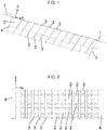
- Fig. 1 shows a schematic view of a grate according to the invention.
- the grate is arranged inclined in the operating state, the bulk material is placed left on top of the screen surface 1 and migrates on this down to the right, in the longitudinal direction x.
- a grate bar 2 can be seen, which runs parallel to the screen surface 1 or whose upper side forms the screen surface 1.
- the gaps between the grate bars 2 are closed by a plurality of transverse plates 3 extending in the width direction y (normal to the plane of the drawing), so that the grate is subdivided into several chambers in the longitudinal direction x.
- the transverse plates 3 are inclined against the conveying direction of the bulk material.
- the transverse plates 3 are bent at the top thereof and are there in the form of a continuous bar on top of the grate bars 2.
- the grate bars 2 are connected to each other by a common support portion 4 and fixed in their mutual position.
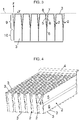
- Fig. 2 which made the top view of the grate Fig. 1 shows can be seen that the height of the grate bars, so their dimension in the height direction z in Fig. 1 , the height of the grate bars 2 is here about 10 to 15 times the width of the grate bars 2.
- the grate comprises in this example seven grate bars 2, are common, depending on the application, four to twelve grate bars 2.
- Fig. 3 shows a vertical section through the grate Fig. 1 respectively.
- Fig. 2 thus a section transverse to the longitudinal axis x of the screen bars 2, so that the width direction y and the height direction z lie in the plane of the drawing.
- Each of the screen bars is formed of three plates 5-7, with first and second plates 5, 6 being arranged at an acute angle to one another and the cavity 8 formed by the two plates 5, 6 is closed by a third flat plate 7 which is parallel to the screen surface 1.
- the first plate 5 is flat and slightly less than half as high as the second plate 6.
- the second plate 6 is angled approximately halfway up, wherein the flat upper part of the plate 6 together with the plate 5, the cavity 8 with the pointed Angle forms.
- the upper part of the plate 6 thus forms together with the plate 5 the - in the height direction z starting at the screen surface 1 - first section 9 of the grate bars 2 from.
- the upper part of the plate 6 and plate 5 in each case include the same angle with the height direction z.
- the width of the widened gap between 2 grate bars remains constant.
- Fig. 4 shows the grate according to the invention in axonometric view, here again the cross plates 3 are clearly visible.
- the plates 5-7 and the transverse plates 3 are usually made of metal and are welded together.
- Fig. 5 shows a sieve with a sieve box 11, which is driven by a drive unit 12.
- the transverse plates 3 and support sections 4 are aligned with each other.
Landscapes
- Engineering & Computer Science (AREA)
- Manufacturing & Machinery (AREA)
- Combined Means For Separation Of Solids (AREA)
Abstract
Siebrost zur größenabhängigen Trennung von Schüttgütern, umfassend eine Vielzahl von parallel, in Förderrichtung des Schüttguts, nebeneinander liegenden, voneinander beabstandeten Roststäben (2), welche eine Siebfläche (1) bilden und welche in Breitenrichtung (y), die parallel zur Siebfläche (1) und normal zur Längsrichtung (x) der Roststäbe (2) verläuft, eine kleinere Abmessung aufweisen als in Höhenrichtung (z), wobei die Höhenrichtung (z) normal zur Siebfläche (1) und normal zur Längsrichtung (x) der Roststäbe (2) verläuft. Der normal zur Längsachse (x) liegende Querschnitt der Roststäbe (2) verjüngt sich in einem an die Siebfläche (1) anschließenden ersten Abschnitt (9) der Roststäbe (2) mit zunehmendem Abstand von der Siebfläche (1), sodass sich in diesem Höhenbereich die Breite eines Spalts zwischen zwei Roststäben (2) in Höhenrichtung erweitert.Grate for the size-dependent separation of bulk materials, comprising a plurality of parallel, in the conveying direction of the bulk material, adjacent, spaced apart grate bars (2), which form a screen surface (1) and which in the width direction (y), parallel to the screen surface (1) and normal to the longitudinal direction (x) of the grate bars (2) has a smaller dimension than in the height direction (z), wherein the height direction (z) normal to the screen surface (1) and normal to the longitudinal direction (x) of the grate bars (2) , The cross section of the grate bars (2) lying normal to the longitudinal axis (x) tapers in a first section (9) of the grate bars (2) adjoining the sieve surface (1) with increasing distance from the sieve surface (1), so that in this height range the width of a gap between two grate bars (2) extended in the height direction.
Description
Die Erfindung betrifft einen Siebrost zur größenabhängigen Trennung von Schüttgütern, umfassend eine Vielzahl von nebeneinander liegenden, voneinander beabstandeten Roststäben, welche eine Siebfläche bilden und welche in Breitenrichtung, die parallel zur Siebfläche und normal zur Längsrichtung der Roststäbe verläuft, eine kleinere Abmessung aufweisen als in Höhenrichtung, wobei die Höhenrichtung normal zur Siebfläche und normal zur Längsrichtung der Roststäbe verläuft und wobei der normal zur Längsachse liegende Querschnitt der Roststäbe sich in einem an die Siebfläche anschließenden ersten Abschnitt der Roststäbe mit zunehmendem Abstand von der Siebfläche verjüngt, sodass sich in diesem Höhenbereich die Breite eines Spalts zwischen zwei Roststäben in Höhenrichtung erweitert.The invention relates to a grate for size-dependent separation of bulk materials, comprising a plurality of juxtaposed, spaced apart grate bars, which form a screen surface and which have a smaller dimension in the width direction which is parallel to the screen surface and normal to the longitudinal direction of the grate bars than in the height direction wherein the height direction is normal to the screen surface and normal to the longitudinal direction of the grate bars and wherein the normal to the longitudinal axis cross-section of the grate bars tapers in a subsequent to the screen surface first portion of the grate bars with increasing distance from the screen surface, so that in this height range, the width a gap between two grate bars in the height direction extended.
Die
Die
Freischwingende Siebmaschinen hingegen, wozu im Wesentlichen die Kreisschwingsiebe, Linearschwingsiebe und Ellipsenschwingsiebe gehören, werden üblicherweise über Federelemente - direkt oder indirekt - an einem Untergrund gelagert. Mittels einer Antriebseinheit wird ein Siebkasten, der einen oder mehrere Siebroste enthält, in Schwingung versetzt.On the other hand, cantilevered screening machines, which essentially include the circular vibrating screens, linear vibrating screens and elliptical vibrating screens, are usually mounted on a base via spring elements, directly or indirectly. By means of a drive unit is a screen box, containing one or more sieves, vibrated.
Es ist eine Aufgabe der vorliegenden Erfindung einen eingangs beschriebenen Siebrost für derartige Siebmaschinen bereit zu stellen, welcher weniger zu Verstopfungen neigt.It is an object of the present invention to provide a screen grate described above for such screening machines, which is less prone to clogging.
Bei einem eingangs genannten Siebrost wird die der Erfindung zugrundeliegende Aufgabe dadurch gelöst, dass der normal zur Längsachse liegende Querschnitt der Roststäbe sich in einem an die Siebfläche anschließenden ersten Abschnitt der Roststäbe mit zunehmendem Abstand von der Siebfläche verjüngt, sodass sich in diesem Höhenbereich die Breite eines Spalts zwischen zwei Roststäben in Höhenrichtung erweitert, wobei die Roststäbe parallel zueinander angeordnet sind, und zwar in Förderrichtung des Schüttguts.In an aforementioned grate, the underlying object of the invention is achieved in that the normal to the longitudinal axis cross-section of the grate bars tapers in a subsequent to the screen surface first portion of the grate bars with increasing distance from the screen surface, so that in this height range, the width of a Gaps extended between two grate bars in the vertical direction, wherein the grate bars are arranged parallel to each other, in the conveying direction of the bulk material.
Dies kann dadurch verwirklicht werden, dass der erste Abschnitt konisch ausgebildet ist, also durch zueinander geneigte Ebenen.This can be realized in that the first portion is conical, that is, by planes inclined toward each other.
In einer einfachen Ausführungsform wird der erste Abschnitt aus zwei ebenen Platten gebildet, die in einem spitzen Winkel zueinander angeordnet sind, wobei der durch die beiden Platten gebildete Hohlraum durch eine dritte ebene Platte verschlossen wird, die parallel zur Siebfläche verläuft.In a simple embodiment, the first portion is formed of two flat plates which are arranged at an acute angle to each other, wherein the cavity formed by the two plates is closed by a third flat plate which is parallel to the screen surface.
Ein zweiter Abschnitt der Roststäbe kann gerade ausgebildet sein, z.B. als ebene Platte, sodass in diesem Höhenbereich die Breite eines Spalts zwischen zwei Roststäben in Höhenrichtung gleich bleibt. Durch die konische Ausbildung des ersten Abschnitts wird die Neigung zu Verstopfungen ja bereits verringert. Der zweite Abschnitt kann insbesondere einteilig mit einer der beiden Platten aus dem ersten Abschnitt ausgebildet sein, die in einem spitzen Winkel zueinander angeordnet sind.A second section of the grate bars may be formed straight, for example as a flat plate, so that in this height range, the width of a gap between two grate bars in the height direction remains the same. Due to the conical design of the first section, the tendency to blockage is already reduced. In particular, the second section may be integral with one of the two panels of the first section be formed, which are arranged at an acute angle to each other.
Der erste Abschnitt kann gleich hoch sein wie der zweite Abschnitt.The first section can be the same height as the second section.
Mehrere in Breitenrichtung verlaufende Querbleche können vorgesehen sein, welche die Spalte zwischen zwei Roststäben in mehrere Kammern unterteilen.A plurality of widthwise transverse panels may be provided which divide the gaps between two grate bars into a plurality of chambers.
In der Regel werden die Roststäbe parallel zueinander angeordnet sein, und zwar in Förderrichtung des Schüttguts.In general, the grate bars will be arranged parallel to each other, in the conveying direction of the bulk material.
Der erfindungsgemäße Rost kommt vorzugsweise bei freischwingenden Siebmaschinen zum Einsatz, welche üblicherweise über Federelemente - direkt oder indirekt - an einem Untergrund gelagert werden, wobei mittels einer Antriebseinheit ein Siebkasten, der einen oder mehrere Siebroste enthält, in Schwingung versetzt wird. Entsprechend kann vorgesehen sein, dass der erfindungsgemäße Siebrost Bestandteil einer freischwingenden Siebmaschine ist. Mit anderen Worten kann die vorliegende Erfindung verwirklicht werden, indem eine freischwingende Siebmaschine mit einem oder mehreren erfindungsgemäßen Siebrosten ausgestattet wird.The grate according to the invention is preferably used in free-running screening machines, which are usually mounted via spring elements - directly or indirectly - on a substrate, wherein by means of a drive unit a screen box containing one or more sieves, is set in vibration. Accordingly, it can be provided that the grate according to the invention is part of a free-moving screening machine. In other words, the present invention can be realized by providing a free-running screening machine with one or more screening gratings according to the invention.
Die Erfindung wird nun anhand eines Ausführungsbeispiels näher erläutert. Die Zeichnungen sind beispielhaft und sollen den Erfindungsgedanken zwar darlegen, ihn aber keinesfalls einengen oder gar abschließend wiedergeben. Dabei zeigt:
- Fig. 1
- eine schematische Seitenansicht eines erfindungsgemäßen Siebrosts,
- Fig. 2
- eine Draufsicht auf den Siebrost aus
Fig. 1 , - Fig. 3
- einen senkrechten Schnitt durch einen Siebrost aus
Fig. 1 , - Fig. 4
- eine axonometrische Ansicht des Siebrosts aus
Fig. 1 , - Fig. 5
- eine axonometrische Ansicht einer Siebmaschine mit mehreren erfindungsgemäßen Siebrosten gemäß
Fig. 1 .
- Fig. 1
- a schematic side view of a grate according to the invention,
- Fig. 2
- a top view of the grate
Fig. 1 . - Fig. 3
- a vertical section through a grate
Fig. 1 . - Fig. 4
- an axonometric view of the grate
Fig. 1 . - Fig. 5
- an axonometric view of a screening machine with several Siebrosten invention according to
Fig. 1 ,
Im Höhenbereich des ersten Abschnitts 9 erweitert sich, von oben nach unten gesehen, somit die Breite eines Spalts zwischen zwei Roststäben 2, während im zweiten Abschnitt 10 die Breite des erweiterten Spalts zwischen 2 Roststäben konstant bleibt.In the height range of the
- 11
- SiebflächeScreen area
- 22
- Roststabgrate bar
- 33
- Querblechbulkhead
- 44
- Auflageabschnittbearing section
- 55
- erste Plattefirst plate
- 66
- zweite Plattesecond plate
- 77
- dritte Plattethird plate
- 88th
- Hohlraumcavity
- 99
-
erster Abschnitt des Roststabs 2first section of the
grate bar 2 - 1010
-
zweiter Abschnitt des Roststabs 2second section of the
grate bar 2 - 1111
- Siebkastenscreenbox
- 1212
- Antriebseinheitdrive unit
- xx
- Längsrichtunglongitudinal direction
- yy
- Breitenrichtungwidth direction
- zz
- Höhenrichtungheight direction
Claims (9)
Priority Applications (1)
| Application Number | Priority Date | Filing Date | Title |
|---|---|---|---|
| EP17168443.4A EP3241618A1 (en) | 2017-04-27 | 2017-04-27 | Sieve grate |
Applications Claiming Priority (1)
| Application Number | Priority Date | Filing Date | Title |
|---|---|---|---|
| EP17168443.4A EP3241618A1 (en) | 2017-04-27 | 2017-04-27 | Sieve grate |
Publications (1)
| Publication Number | Publication Date |
|---|---|
| EP3241618A1 true EP3241618A1 (en) | 2017-11-08 |
Family
ID=58638776
Family Applications (1)
| Application Number | Title | Priority Date | Filing Date |
|---|---|---|---|
| EP17168443.4A Withdrawn EP3241618A1 (en) | 2017-04-27 | 2017-04-27 | Sieve grate |
Country Status (1)
| Country | Link |
|---|---|
| EP (1) | EP3241618A1 (en) |
Cited By (1)
| Publication number | Priority date | Publication date | Assignee | Title |
|---|---|---|---|---|
| CN109622366A (en) * | 2019-01-11 | 2019-04-16 | 北京昊辰投资担保有限公司 | Material separator and separation method |
Citations (8)
| Publication number | Priority date | Publication date | Assignee | Title |
|---|---|---|---|---|
| GB425877A (en) * | 1934-09-13 | 1935-03-22 | Louis Herrmann | Improvements in or relating to sifting and screening grates or sieves |
| US4268384A (en) | 1977-03-21 | 1981-05-19 | Rosaen Borje O | Spin-off filter head assembly |
| US4283278A (en) * | 1978-03-23 | 1981-08-11 | N. Greening Limited | Screens |
| WO1996026794A1 (en) * | 1995-02-28 | 1996-09-06 | Neil Deryck Bray Graham | Screening device and apparatus including same |
| WO2003013742A1 (en) * | 2001-08-07 | 2003-02-20 | Power-Glides Screens Limited | Suspension screen raking system |
| WO2003084802A1 (en) * | 2002-04-09 | 2003-10-16 | Thyssenkrupp Stahl Ag | Y-shaped node structure for the supporting frame of a motor vehicle |
| AT509855A4 (en) * | 2010-07-29 | 2011-12-15 | Ife Aufbereitungstechnik Gmbh | SCREE |
| DE102014011679A1 (en) | 2013-08-20 | 2015-02-26 | Andritz Fiedler Gmbh | Profiled sieve and sieve device made of profiled sieve bars |
-
2017
- 2017-04-27 EP EP17168443.4A patent/EP3241618A1/en not_active Withdrawn
Patent Citations (8)
| Publication number | Priority date | Publication date | Assignee | Title |
|---|---|---|---|---|
| GB425877A (en) * | 1934-09-13 | 1935-03-22 | Louis Herrmann | Improvements in or relating to sifting and screening grates or sieves |
| US4268384A (en) | 1977-03-21 | 1981-05-19 | Rosaen Borje O | Spin-off filter head assembly |
| US4283278A (en) * | 1978-03-23 | 1981-08-11 | N. Greening Limited | Screens |
| WO1996026794A1 (en) * | 1995-02-28 | 1996-09-06 | Neil Deryck Bray Graham | Screening device and apparatus including same |
| WO2003013742A1 (en) * | 2001-08-07 | 2003-02-20 | Power-Glides Screens Limited | Suspension screen raking system |
| WO2003084802A1 (en) * | 2002-04-09 | 2003-10-16 | Thyssenkrupp Stahl Ag | Y-shaped node structure for the supporting frame of a motor vehicle |
| AT509855A4 (en) * | 2010-07-29 | 2011-12-15 | Ife Aufbereitungstechnik Gmbh | SCREE |
| DE102014011679A1 (en) | 2013-08-20 | 2015-02-26 | Andritz Fiedler Gmbh | Profiled sieve and sieve device made of profiled sieve bars |
Cited By (1)
| Publication number | Priority date | Publication date | Assignee | Title |
|---|---|---|---|---|
| CN109622366A (en) * | 2019-01-11 | 2019-04-16 | 北京昊辰投资担保有限公司 | Material separator and separation method |
Similar Documents
| Publication | Publication Date | Title |
|---|---|---|
| DE102014009702B3 (en) | Plastic screen covering for a screening machine for classifying in particular fine-grained bulk material | |
| DE3006364B1 (en) | Perforated plate sieve bottom with self-cleaning effect | |
| DE3827259A1 (en) | SCREEN ARRANGEMENT | |
| EP0521192A1 (en) | Element for screen | |
| DE202016103754U1 (en) | screening machine | |
| EP3241618A1 (en) | Sieve grate | |
| EP3275562B1 (en) | Finger screen | |
| AT15451U1 (en) | grate | |
| EP1228814A2 (en) | Screening machine | |
| AT505122B1 (en) | sieve | |
| EP2412451B1 (en) | Filter | |
| DE3790016C2 (en) | ||
| DE102014009704B3 (en) | Plastic screen covering for a screening machine for classifying in particular coarse-grained bulk material | |
| DE602004011125T2 (en) | STRUCTURAL ARRANGEMENT FOR SWING FACILITIES | |
| DE19904091A1 (en) | Bar grating for screening bulk materials, e.g. root vegetables | |
| DE10065930B4 (en) | Method of making screens useful for wet screening of paper pulp suspensions | |
| DE19506084A1 (en) | Wire unit for suspensions, e.g. pulp or sludge | |
| DE2923662C2 (en) | Vibrating screen, especially circular vibrating screen | |
| EP3917690B1 (en) | Vibrating screening system, consisting of at least two screening machines arranged in a row | |
| DE10116367A1 (en) | Screening device for wet screening of paper fiber suspensions | |
| EP3248695A1 (en) | Screening device | |
| AT524317B1 (en) | Drip bar and kit for use in a paper web forming installation | |
| EP2409784B1 (en) | Screening roller for a device for screening decomposable material | |
| DE19635156C2 (en) | Process for the production of sieves | |
| AT10774U1 (en) | SIEVE SHAKER |
Legal Events
| Date | Code | Title | Description |
|---|---|---|---|
| PUAI | Public reference made under article 153(3) epc to a published international application that has entered the european phase |
Free format text: ORIGINAL CODE: 0009012 |
|
| AK | Designated contracting states |
Kind code of ref document: A1 Designated state(s): AL AT BE BG CH CY CZ DE DK EE ES FI FR GB GR HR HU IE IS IT LI LT LU LV MC MK MT NL NO PL PT RO RS SE SI SK SM TR |
|
| AX | Request for extension of the european patent |
Extension state: BA ME |
|
| STAA | Information on the status of an ep patent application or granted ep patent |
Free format text: STATUS: THE APPLICATION IS DEEMED TO BE WITHDRAWN |
|
| 18D | Application deemed to be withdrawn |
Effective date: 20180509 |