EP3239978B1 - Encoding and decoding of pulse positions of tracks of an audio signal - Google Patents
Encoding and decoding of pulse positions of tracks of an audio signal Download PDFInfo
- Publication number
- EP3239978B1 EP3239978B1 EP17171964.4A EP17171964A EP3239978B1 EP 3239978 B1 EP3239978 B1 EP 3239978B1 EP 17171964 A EP17171964 A EP 17171964A EP 3239978 B1 EP3239978 B1 EP 3239978B1
- Authority
- EP
- European Patent Office
- Prior art keywords
- pulse
- track
- positions
- tracks
- pulses
- Prior art date
- Legal status (The legal status is an assumption and is not a legal conclusion. Google has not performed a legal analysis and makes no representation as to the accuracy of the status listed.)
- Active
Links
- 230000005236 sound signal Effects 0.000 title claims description 64
- 238000000034 method Methods 0.000 claims description 51
- 238000004590 computer program Methods 0.000 claims description 10
- 238000012360 testing method Methods 0.000 claims description 9
- 238000005192 partition Methods 0.000 description 19
- 238000013459 approach Methods 0.000 description 16
- 239000013598 vector Substances 0.000 description 13
- 238000012545 processing Methods 0.000 description 7
- 230000006870 function Effects 0.000 description 4
- 230000003044 adaptive effect Effects 0.000 description 3
- 230000005284 excitation Effects 0.000 description 2
- 238000007781 pre-processing Methods 0.000 description 2
- 230000003595 spectral effect Effects 0.000 description 2
- 230000005540 biological transmission Effects 0.000 description 1
- 238000004891 communication Methods 0.000 description 1
- 238000011156 evaluation Methods 0.000 description 1
- 238000013507 mapping Methods 0.000 description 1
- 238000012986 modification Methods 0.000 description 1
- 230000004048 modification Effects 0.000 description 1
- 238000012805 post-processing Methods 0.000 description 1
- 238000010561 standard procedure Methods 0.000 description 1
- 230000003068 static effect Effects 0.000 description 1
Images


Classifications
-
- G—PHYSICS
- G10—MUSICAL INSTRUMENTS; ACOUSTICS
- G10L—SPEECH ANALYSIS TECHNIQUES OR SPEECH SYNTHESIS; SPEECH RECOGNITION; SPEECH OR VOICE PROCESSING TECHNIQUES; SPEECH OR AUDIO CODING OR DECODING
- G10L19/00—Speech or audio signals analysis-synthesis techniques for redundancy reduction, e.g. in vocoders; Coding or decoding of speech or audio signals, using source filter models or psychoacoustic analysis
- G10L19/02—Speech or audio signals analysis-synthesis techniques for redundancy reduction, e.g. in vocoders; Coding or decoding of speech or audio signals, using source filter models or psychoacoustic analysis using spectral analysis, e.g. transform vocoders or subband vocoders
- G10L19/028—Noise substitution, i.e. substituting non-tonal spectral components by noisy source
-
- G—PHYSICS
- G10—MUSICAL INSTRUMENTS; ACOUSTICS
- G10L—SPEECH ANALYSIS TECHNIQUES OR SPEECH SYNTHESIS; SPEECH RECOGNITION; SPEECH OR VOICE PROCESSING TECHNIQUES; SPEECH OR AUDIO CODING OR DECODING
- G10L19/00—Speech or audio signals analysis-synthesis techniques for redundancy reduction, e.g. in vocoders; Coding or decoding of speech or audio signals, using source filter models or psychoacoustic analysis
- G10L19/04—Speech or audio signals analysis-synthesis techniques for redundancy reduction, e.g. in vocoders; Coding or decoding of speech or audio signals, using source filter models or psychoacoustic analysis using predictive techniques
- G10L19/08—Determination or coding of the excitation function; Determination or coding of the long-term prediction parameters
-
- G—PHYSICS
- G10—MUSICAL INSTRUMENTS; ACOUSTICS
- G10L—SPEECH ANALYSIS TECHNIQUES OR SPEECH SYNTHESIS; SPEECH RECOGNITION; SPEECH OR VOICE PROCESSING TECHNIQUES; SPEECH OR AUDIO CODING OR DECODING
- G10L19/00—Speech or audio signals analysis-synthesis techniques for redundancy reduction, e.g. in vocoders; Coding or decoding of speech or audio signals, using source filter models or psychoacoustic analysis
- G10L19/04—Speech or audio signals analysis-synthesis techniques for redundancy reduction, e.g. in vocoders; Coding or decoding of speech or audio signals, using source filter models or psychoacoustic analysis using predictive techniques
-
- G—PHYSICS
- G10—MUSICAL INSTRUMENTS; ACOUSTICS
- G10L—SPEECH ANALYSIS TECHNIQUES OR SPEECH SYNTHESIS; SPEECH RECOGNITION; SPEECH OR VOICE PROCESSING TECHNIQUES; SPEECH OR AUDIO CODING OR DECODING
- G10L19/00—Speech or audio signals analysis-synthesis techniques for redundancy reduction, e.g. in vocoders; Coding or decoding of speech or audio signals, using source filter models or psychoacoustic analysis
- G10L19/005—Correction of errors induced by the transmission channel, if related to the coding algorithm
-
- G—PHYSICS
- G10—MUSICAL INSTRUMENTS; ACOUSTICS
- G10L—SPEECH ANALYSIS TECHNIQUES OR SPEECH SYNTHESIS; SPEECH RECOGNITION; SPEECH OR VOICE PROCESSING TECHNIQUES; SPEECH OR AUDIO CODING OR DECODING
- G10L19/00—Speech or audio signals analysis-synthesis techniques for redundancy reduction, e.g. in vocoders; Coding or decoding of speech or audio signals, using source filter models or psychoacoustic analysis
- G10L19/04—Speech or audio signals analysis-synthesis techniques for redundancy reduction, e.g. in vocoders; Coding or decoding of speech or audio signals, using source filter models or psychoacoustic analysis using predictive techniques
- G10L19/08—Determination or coding of the excitation function; Determination or coding of the long-term prediction parameters
- G10L19/10—Determination or coding of the excitation function; Determination or coding of the long-term prediction parameters the excitation function being a multipulse excitation
-
- G—PHYSICS
- G10—MUSICAL INSTRUMENTS; ACOUSTICS
- G10K—SOUND-PRODUCING DEVICES; METHODS OR DEVICES FOR PROTECTING AGAINST, OR FOR DAMPING, NOISE OR OTHER ACOUSTIC WAVES IN GENERAL; ACOUSTICS NOT OTHERWISE PROVIDED FOR
- G10K11/00—Methods or devices for transmitting, conducting or directing sound in general; Methods or devices for protecting against, or for damping, noise or other acoustic waves in general
- G10K11/16—Methods or devices for protecting against, or for damping, noise or other acoustic waves in general
-
- G—PHYSICS
- G10—MUSICAL INSTRUMENTS; ACOUSTICS
- G10L—SPEECH ANALYSIS TECHNIQUES OR SPEECH SYNTHESIS; SPEECH RECOGNITION; SPEECH OR VOICE PROCESSING TECHNIQUES; SPEECH OR AUDIO CODING OR DECODING
- G10L19/00—Speech or audio signals analysis-synthesis techniques for redundancy reduction, e.g. in vocoders; Coding or decoding of speech or audio signals, using source filter models or psychoacoustic analysis
- G10L19/012—Comfort noise or silence coding
-
- G—PHYSICS
- G10—MUSICAL INSTRUMENTS; ACOUSTICS
- G10L—SPEECH ANALYSIS TECHNIQUES OR SPEECH SYNTHESIS; SPEECH RECOGNITION; SPEECH OR VOICE PROCESSING TECHNIQUES; SPEECH OR AUDIO CODING OR DECODING
- G10L19/00—Speech or audio signals analysis-synthesis techniques for redundancy reduction, e.g. in vocoders; Coding or decoding of speech or audio signals, using source filter models or psychoacoustic analysis
- G10L19/02—Speech or audio signals analysis-synthesis techniques for redundancy reduction, e.g. in vocoders; Coding or decoding of speech or audio signals, using source filter models or psychoacoustic analysis using spectral analysis, e.g. transform vocoders or subband vocoders
- G10L19/0212—Speech or audio signals analysis-synthesis techniques for redundancy reduction, e.g. in vocoders; Coding or decoding of speech or audio signals, using source filter models or psychoacoustic analysis using spectral analysis, e.g. transform vocoders or subband vocoders using orthogonal transformation
-
- G—PHYSICS
- G10—MUSICAL INSTRUMENTS; ACOUSTICS
- G10L—SPEECH ANALYSIS TECHNIQUES OR SPEECH SYNTHESIS; SPEECH RECOGNITION; SPEECH OR VOICE PROCESSING TECHNIQUES; SPEECH OR AUDIO CODING OR DECODING
- G10L19/00—Speech or audio signals analysis-synthesis techniques for redundancy reduction, e.g. in vocoders; Coding or decoding of speech or audio signals, using source filter models or psychoacoustic analysis
- G10L19/02—Speech or audio signals analysis-synthesis techniques for redundancy reduction, e.g. in vocoders; Coding or decoding of speech or audio signals, using source filter models or psychoacoustic analysis using spectral analysis, e.g. transform vocoders or subband vocoders
- G10L19/022—Blocking, i.e. grouping of samples in time; Choice of analysis windows; Overlap factoring
- G10L19/025—Detection of transients or attacks for time/frequency resolution switching
-
- G—PHYSICS
- G10—MUSICAL INSTRUMENTS; ACOUSTICS
- G10L—SPEECH ANALYSIS TECHNIQUES OR SPEECH SYNTHESIS; SPEECH RECOGNITION; SPEECH OR VOICE PROCESSING TECHNIQUES; SPEECH OR AUDIO CODING OR DECODING
- G10L19/00—Speech or audio signals analysis-synthesis techniques for redundancy reduction, e.g. in vocoders; Coding or decoding of speech or audio signals, using source filter models or psychoacoustic analysis
- G10L19/02—Speech or audio signals analysis-synthesis techniques for redundancy reduction, e.g. in vocoders; Coding or decoding of speech or audio signals, using source filter models or psychoacoustic analysis using spectral analysis, e.g. transform vocoders or subband vocoders
- G10L19/03—Spectral prediction for preventing pre-echo; Temporary noise shaping [TNS], e.g. in MPEG2 or MPEG4
-
- G—PHYSICS
- G10—MUSICAL INSTRUMENTS; ACOUSTICS
- G10L—SPEECH ANALYSIS TECHNIQUES OR SPEECH SYNTHESIS; SPEECH RECOGNITION; SPEECH OR VOICE PROCESSING TECHNIQUES; SPEECH OR AUDIO CODING OR DECODING
- G10L19/00—Speech or audio signals analysis-synthesis techniques for redundancy reduction, e.g. in vocoders; Coding or decoding of speech or audio signals, using source filter models or psychoacoustic analysis
- G10L19/04—Speech or audio signals analysis-synthesis techniques for redundancy reduction, e.g. in vocoders; Coding or decoding of speech or audio signals, using source filter models or psychoacoustic analysis using predictive techniques
- G10L19/06—Determination or coding of the spectral characteristics, e.g. of the short-term prediction coefficients
- G10L19/07—Line spectrum pair [LSP] vocoders
-
- G—PHYSICS
- G10—MUSICAL INSTRUMENTS; ACOUSTICS
- G10L—SPEECH ANALYSIS TECHNIQUES OR SPEECH SYNTHESIS; SPEECH RECOGNITION; SPEECH OR VOICE PROCESSING TECHNIQUES; SPEECH OR AUDIO CODING OR DECODING
- G10L19/00—Speech or audio signals analysis-synthesis techniques for redundancy reduction, e.g. in vocoders; Coding or decoding of speech or audio signals, using source filter models or psychoacoustic analysis
- G10L19/04—Speech or audio signals analysis-synthesis techniques for redundancy reduction, e.g. in vocoders; Coding or decoding of speech or audio signals, using source filter models or psychoacoustic analysis using predictive techniques
- G10L19/08—Determination or coding of the excitation function; Determination or coding of the long-term prediction parameters
- G10L19/10—Determination or coding of the excitation function; Determination or coding of the long-term prediction parameters the excitation function being a multipulse excitation
- G10L19/107—Sparse pulse excitation, e.g. by using algebraic codebook
-
- G—PHYSICS
- G10—MUSICAL INSTRUMENTS; ACOUSTICS
- G10L—SPEECH ANALYSIS TECHNIQUES OR SPEECH SYNTHESIS; SPEECH RECOGNITION; SPEECH OR VOICE PROCESSING TECHNIQUES; SPEECH OR AUDIO CODING OR DECODING
- G10L19/00—Speech or audio signals analysis-synthesis techniques for redundancy reduction, e.g. in vocoders; Coding or decoding of speech or audio signals, using source filter models or psychoacoustic analysis
- G10L19/04—Speech or audio signals analysis-synthesis techniques for redundancy reduction, e.g. in vocoders; Coding or decoding of speech or audio signals, using source filter models or psychoacoustic analysis using predictive techniques
- G10L19/08—Determination or coding of the excitation function; Determination or coding of the long-term prediction parameters
- G10L19/12—Determination or coding of the excitation function; Determination or coding of the long-term prediction parameters the excitation function being a code excitation, e.g. in code excited linear prediction [CELP] vocoders
- G10L19/13—Residual excited linear prediction [RELP]
-
- G—PHYSICS
- G10—MUSICAL INSTRUMENTS; ACOUSTICS
- G10L—SPEECH ANALYSIS TECHNIQUES OR SPEECH SYNTHESIS; SPEECH RECOGNITION; SPEECH OR VOICE PROCESSING TECHNIQUES; SPEECH OR AUDIO CODING OR DECODING
- G10L19/00—Speech or audio signals analysis-synthesis techniques for redundancy reduction, e.g. in vocoders; Coding or decoding of speech or audio signals, using source filter models or psychoacoustic analysis
- G10L19/04—Speech or audio signals analysis-synthesis techniques for redundancy reduction, e.g. in vocoders; Coding or decoding of speech or audio signals, using source filter models or psychoacoustic analysis using predictive techniques
- G10L19/16—Vocoder architecture
- G10L19/18—Vocoders using multiple modes
- G10L19/22—Mode decision, i.e. based on audio signal content versus external parameters
-
- G—PHYSICS
- G10—MUSICAL INSTRUMENTS; ACOUSTICS
- G10L—SPEECH ANALYSIS TECHNIQUES OR SPEECH SYNTHESIS; SPEECH RECOGNITION; SPEECH OR VOICE PROCESSING TECHNIQUES; SPEECH OR AUDIO CODING OR DECODING
- G10L21/00—Speech or voice signal processing techniques to produce another audible or non-audible signal, e.g. visual or tactile, in order to modify its quality or its intelligibility
- G10L21/02—Speech enhancement, e.g. noise reduction or echo cancellation
- G10L21/0208—Noise filtering
- G10L21/0216—Noise filtering characterised by the method used for estimating noise
-
- G—PHYSICS
- G10—MUSICAL INSTRUMENTS; ACOUSTICS
- G10L—SPEECH ANALYSIS TECHNIQUES OR SPEECH SYNTHESIS; SPEECH RECOGNITION; SPEECH OR VOICE PROCESSING TECHNIQUES; SPEECH OR AUDIO CODING OR DECODING
- G10L25/00—Speech or voice analysis techniques not restricted to a single one of groups G10L15/00 - G10L21/00
- G10L25/03—Speech or voice analysis techniques not restricted to a single one of groups G10L15/00 - G10L21/00 characterised by the type of extracted parameters
- G10L25/06—Speech or voice analysis techniques not restricted to a single one of groups G10L15/00 - G10L21/00 characterised by the type of extracted parameters the extracted parameters being correlation coefficients
-
- G—PHYSICS
- G10—MUSICAL INSTRUMENTS; ACOUSTICS
- G10L—SPEECH ANALYSIS TECHNIQUES OR SPEECH SYNTHESIS; SPEECH RECOGNITION; SPEECH OR VOICE PROCESSING TECHNIQUES; SPEECH OR AUDIO CODING OR DECODING
- G10L25/00—Speech or voice analysis techniques not restricted to a single one of groups G10L15/00 - G10L21/00
- G10L25/78—Detection of presence or absence of voice signals
-
- G—PHYSICS
- G10—MUSICAL INSTRUMENTS; ACOUSTICS
- G10L—SPEECH ANALYSIS TECHNIQUES OR SPEECH SYNTHESIS; SPEECH RECOGNITION; SPEECH OR VOICE PROCESSING TECHNIQUES; SPEECH OR AUDIO CODING OR DECODING
- G10L19/00—Speech or audio signals analysis-synthesis techniques for redundancy reduction, e.g. in vocoders; Coding or decoding of speech or audio signals, using source filter models or psychoacoustic analysis
- G10L19/04—Speech or audio signals analysis-synthesis techniques for redundancy reduction, e.g. in vocoders; Coding or decoding of speech or audio signals, using source filter models or psychoacoustic analysis using predictive techniques
- G10L19/26—Pre-filtering or post-filtering
Definitions
- ACELP encoders usually encode an audio signal by determining predictive filter coefficients. To achieve better encoding, ACELP encoders determine a residual signal, also referred to as target signal, based on the audio signal to be encoded, and based on the already determined predictive filter coefficients.
- the residual signal may, for example, be a difference signal representing a difference between the audio signal to be encoded and the signal portions that are encoded by the predictive filter coefficients, and, possibly, by adaptive filter coefficients resulting from a pitch analysis.
- the ACELP encoder then aims to encode the residual signal. For this, the encoder encodes algebraic codebook parameters, which are used to encode the residual signal.
- each can attain roughly 6.6 x 10 ⁇ 21 states, which can, according to embodiments, be encoded by 73 bits, which is approximately 21% more efficient than the encoding of the above-described state-of-the-art encoder using 92 bits.
- the embodiments are, moreover, based on the finding, that, if the encoding strategy uses a pre-determined number of bits, such that any configuration with the same number of pulses on each track requires the same number of bits. If the number of bits available is fixed, it is then possible directly to choose how many pulses can be encoded with the given amount of bits thus enabling encoding with a pre-determined quality. Moreover, with this approach, it is not necessary to try different amounts of pulses until the desired bit-rate is achieved, but we can directly choose the right amount of pulses, thereby reducing complexity.
- the pulse information decoder may be adapted to conduct the test by comparing, whether the state number or an updated state number is greater than, greater than or equal to, smaller than, or smaller than or equal to the threshold value, and wherein the analyzing unit is furthermore adapted to update the state number or an updated state number depending on the result of the test.
- the pulse information decoder may be configured to compare the state number or the updated state number with the threshold value for each track position of one of the plurality of tracks.
- the number of states for the first row has been obtained from the two previous tables. By addition of the number of states in the first row, we see that this configuration has 18 states.
- the number of possible configurations for N track positions having p pulses may be calculated.
- the pulse information encoder can now analyze the track: If the first position in the track does not have a pulse, then the remaining N-1 positions have p signed pulses, and to describe this constellation, we need only f(p, N -1 ) states.
- the pulse information decoder can reduce the number of remaining positions by one. Repeating this procedure until there are no pulses left, would provide the unsigned positions of pulses.
- the sign of the pulse is determined by the last bit. Then, the remaining state is shifted one step right to obtain an updated state number.
- a pulse information encoder algorithm is provided:
- each track can then be determined in the decoder by dividing the joint state by f(p k ,N) , whereby the remainder is the state of the last track and the integer part is the joint state of the remaining tracks. If the number of tracks is other than 4, we can readily add or reduce the number of terms in the above equation appropriately.
- a pulse information encoder algorithm is provided, that can be described in pseudo-code by
- an embodiment of the inventive method is, therefore, a computer program having a program code for performing one of the methods described herein, when the computer program runs on a computer.
Landscapes
- Engineering & Computer Science (AREA)
- Physics & Mathematics (AREA)
- Multimedia (AREA)
- Acoustics & Sound (AREA)
- Audiology, Speech & Language Pathology (AREA)
- Human Computer Interaction (AREA)
- Health & Medical Sciences (AREA)
- Signal Processing (AREA)
- Computational Linguistics (AREA)
- Spectroscopy & Molecular Physics (AREA)
- Quality & Reliability (AREA)
- General Physics & Mathematics (AREA)
- Mathematical Analysis (AREA)
- Mathematical Optimization (AREA)
- Mathematical Physics (AREA)
- Pure & Applied Mathematics (AREA)
- Theoretical Computer Science (AREA)
- Algebra (AREA)
- Compression, Expansion, Code Conversion, And Decoders (AREA)
Description
- The present invention relates to the field of audio processing and audio coding, in particular to encoding and decoding of pulse positions of tracks in an audio signal.
- Audio processing and/or coding has advanced in many ways. In audio coding, linear predictive coders play an important role. When encoding an audio signal, e.g. an audio signal comprising speech, linear predictive encoders usually encode a representation of the spectral envelope of the audio signal. To this end, linear predictive encoders may determine predictive filter coefficients to represent the spectral envelope of sound in encoded form. The filter coefficients may then be used by a linear predictive decoder to decode the encoded audio signal by generating a synthesized audio signal using the predictive filter coefficients.
- Important examples for linear predictive coders are ACELP coders (ACELP = Algebraic Code-Exited Linear Prediction coders). ACELP coders are widely used, for example, in USAC (USAC = Unified Speech and Audio Coding) and may have further application fields, for example in LD-USAC (Low Delay Unified Speech and Audio Coding).
- ACELP encoders usually encode an audio signal by determining predictive filter coefficients. To achieve better encoding, ACELP encoders determine a residual signal, also referred to as target signal, based on the audio signal to be encoded, and based on the already determined predictive filter coefficients. The residual signal may, for example, be a difference signal representing a difference between the audio signal to be encoded and the signal portions that are encoded by the predictive filter coefficients, and, possibly, by adaptive filter coefficients resulting from a pitch analysis. The ACELP encoder then aims to encode the residual signal. For this, the encoder encodes algebraic codebook parameters, which are used to encode the residual signal.
- To encode the residual signal, algebraic codebooks are used. Usually, algebraic codebooks comprise a plurality of tracks, for example, four tracks each comprising 16 track positions. In such a configuration, a total of 4 · 16 = 64 sample positions can be represented by a respective algebraic codebook, for example, corresponding to the number of samples of a subframe of the audio signal to be encoded.
- The tracks of the codebook may be interleaved such that
track 0 of the codebook may representsamples track 1 of the codebook may representsamples track 2 of the codebook may representsamples track 3 of the codebook may representsamples - For encoding the residual signal, when encoding, a codebook configuration may be chosen, that best represents the remaining signal portions of the residual signal. For this, the available pulses may be positioned at suitable track positions that reflect best the signal portions to be encoded. Moreover, it may be specified, whether a corresponding pulse is positive or negative.
- On a decoder side, an ACELP decoder would at first decode the algebraic codebook parameters. The ACELP decoder may also decode the adaptive codebook parameters. To determine the algebraic codebook parameters, the ACELP decoder may determine the plurality of pulse positions for each track of an algebraic codebook. Moreover, the ACELP decoder may also decode, whether a pulse at a track position is a positive or a negative pulse. Furthermore, the ACELP decoder may also decode the adaptive codebook parameters. Based on this information, the ACELP decoder usually generates an excitation signal. The ACELP decoder then applies the predictive filter coefficients on the excitation signal to generate a synthesized audio signal to obtain the decoded audio signal.
- In ACELP, pulses on a track are generally encoded as follows. If the track is of length 16 and if the number of pulses on this track is one, then we can encode the pulse position by its position (4 bits) and sign (1 bit), totaling 5 bits. If the track is of length 16 and the number of pulses is two, then the first pulse is encoded by its position (4 bits) and sign (1 bit). For the second pulse we need to encode the position only (4 bits), since we can choose that the sign of the second pulse is positive if it is to the left of the first pulse, negative if it is to the right of the first pulse and the same sign as the first pulse if it is at the same position as the first pulse. In total, we therefore need 9 bits to encode 2 pulses. In comparison to encoding the pulse positions separately, by 5 bits each, we thus save 1 bit for every pair of pulses.
- Encoding a larger number of pulses than 2, we can encode pulses pair-wise and if the number of pulses is odd, encode the last pulse separately. Then, for example, for a track of 5 pulses, we would need 9+9+5 = 23 bits. If we have 4 tracks, then 4 x 23 = 92 bits would be required for encoding a subframe of length 64 with 4 tracks and 5 pulses per track. However, it would be very appreciated, if the number of bits could furthermore be reduced,
- Virette et al, "Enhanced Pulse Indexing CE for ACELP in USAC", ISO/ IEC JTC1/SC29/WG11, 95th MPEG meeting, January 2011, pages 11-13, XP030047872, presents pulse indexing and de-indexing based on a permutation method for ACELP encoding and decoding.
- It would be very appreciated, if an apparatus for encoding and a respective apparatus for decoding with improved encoding or decoding concepts would be provided, which have means to encode or decode pulse information in an improved way using fewer bits for pulse information representation, as this would, for example, reduce the transmission rate for transmitting a respectively encoded audio signal, and as furthermore, this would, for example, reduce the storage needed to store a respectively encoded audio signal.
- It is therefore an object of the present invention to provide improved concepts for encoding and decoding of pulses of tracks of an audio signal. The objects of the present invention are achieved by an apparatus for decoding according to
claim 1, an apparatus for encoding according toclaim 4, a method for decoding according toclaim 5, a method for encoding according toclaim 6, and a computer program according toclaim 7. - As noted above, the invention is set forth in the independent claims. All following occurrences of the word "embodiment(s)", if referring to feature combinations different from those defined by the independent claims, refer to examples which were originally filed but which do not represent embodiments of the presently claimed invention; these examples are still shown for illustrative purposes only.
- According to embodiments, it is assumed that one state number is available for an apparatus for decoding. It is furthermore assumed that a track positions number, indicating the total number of track positions of at least one of the tracks associated with the encoded audio signal, and a total pulses number, indicating the number of pulses of at least one of the tracks, is available for a decoding apparatus of the present invention. Preferably, the track positions number and the total pulses number is available for each track associated with an encoded audio signal.
- For example, having 4 tracks with 5 pulses, each can attain roughly 6.6 x 10^21 states, which can, according to embodiments, be encoded by 73 bits, which is approximately 21% more efficient than the encoding of the above-described state-of-the-art encoder using 92 bits.
- At first, a concept is provided how to encode a plurality of pulse positions of a track of an audio signal in an efficient way. In the following, the concept is extended to allow to encode not only the position of the pulses of a track, but also whether the pulse is positive or negative. Furthermore, the concept is then extended to allow to encode pulse information for a plurality of tracks in an efficient manner. The concepts are correspondingly applicable on a decoder side.
- In addition, the embodiments are, moreover, based on the finding, that, if the encoding strategy uses a pre-determined number of bits, such that any configuration with the same number of pulses on each track requires the same number of bits. If the number of bits available is fixed, it is then possible directly to choose how many pulses can be encoded with the given amount of bits thus enabling encoding with a pre-determined quality. Moreover, with this approach, it is not necessary to try different amounts of pulses until the desired bit-rate is achieved, but we can directly choose the right amount of pulses, thereby reducing complexity.
- Based on the above assumptions, the plurality of pulse positions of a track of an audio signal frame may be encoded and/or decoded.
- While the present invention can be employed for encoding or decoding any kind of audio signals, for example, speech signals or music signals, the present invention is particularly useful for encoding or decoding speech signals.
- In another embodiment, the pulse information decoder is furthermore adapted to decode a plurality of pulse signs using the track positions number, the total pulses number and the state number, wherein each one of the pulse signs indicates a sign of one of the plurality of pulses. The signal decoder may be adapted to decode the encoded audio signal by generating a synthesized audio signal furthermore using the plurality of pulse signs.
- According to a further embodiment, wherein the one or more tracks may comprise at least a last track and one or more other tracks, the pulse information decoder may be adapted to generate a first substate number and a second substate number from the state number. The pulse information decoder may be configured to decode a first group of the pulse positions based on the first substate number, and the pulse information decoder may furthermore be configured to decode a second group of the pulse positions based on the second substate number. The second group of the pulse positions may only consist of pulse positions indicating track positions of the last track. The first group of the pulse positions only consists of pulse positions indicating track positions of the one or more other tracks.
- According to another embodiment, the pulse information decoder may be configured to separate the state number into the first substate number and the second substate number by dividing the state number by f(pk, N) to obtain an integer part and a remainder as a division result, wherein the integer part is the first substate number and wherein the remainder is the second substate number, wherein pk indicates for each one of the one or more tracks the number of pulses, and wherein N indicates for each one of the one or more tracks the number of track positions. Here, f(pk, N) is a function that returns the number of states that can be achieved in a track of length N with pk pulses.
- In another embodiment, the pulse information decoder may be adapted to conduct a test comparing the state number or an updated state number with a threshold value.
- The pulse information decoder may be adapted to conduct the test by comparing, whether the state number or an updated state number is greater than, greater than or equal to, smaller than, or smaller than or equal to the threshold value, and wherein the analyzing unit is furthermore adapted to update the state number or an updated state number depending on the result of the test.
- In an embodiment, the pulse information decoder may be configured to compare the state number or the updated state number with the threshold value for each track position of one of the plurality of tracks.
- According to an embodiment, the pulse information decoder may be configured to divide one of the tracks into a first track partition, comprising at least one track position of the plurality of track positions, and into a second track partition, comprising the remaining other track positions of the plurality of track positions. The pulse information decoder may be configured to generate a first substate number and a second substate number based on the state number. Moreover, the pulse information decoder may be configured to decode a first group of pulse positions associated with the first track partition based on the first substate number. Furthermore, the pulse information decoder may be configured to decode a second group of pulse positions associated with the second track partition based on the second substate number.
- According to an embodiment, an apparatus for encoding an audio signal is provided. The apparatus comprises a signal processor adapted to determine a plurality of predictive filter coefficients being associated with the audio signal, for generating a residual signal based on the audio signal and the plurality of predictive filter coefficients. Moreover, the apparatus comprises a pulse information encoder adapted to encode a plurality of pulse positions relating to one or more tracks to encode the audio signal, the one or more tracks being associated with the residual signal. Each one of the tracks has a plurality of track positions and a plurality of pulses. Each one of the pulse positions indicates one of the track positions of one of the tracks to indicate a position of one of the pulses of the track. The pulse information encoder is configured to encode the plurality of pulse positions by generating a state number, such that the pulse positions can be decoded only based on the state number, a track positions number indicating a total number of the track positions of at least one of the tracks, and a total pulses number indicating a total number of the pulses of at least one of the tracks.
- According to another embodiment, the pulse information encoder may be adapted to encode a plurality of pulse signs, wherein each one of the pulse signs indicates a sign of one of the plurality of pulses. The pulse information encoder may furthermore be configured to encode the plurality of pulse signs by generating the state number, such that the pulse signs can be decoded only based on the state number, the track positions number indicating a total number of the track positions of at least one of the tracks, and the total pulses number.
- In an embodiment, the pulse information encoder is adapted to add an integer value to an intermediate number for each pulse at a track position for each track position of one of the tracks, to obtain the state number.
- According to another embodiment, the pulse information encoder may be configured to divide one of the tracks into a first track partition, comprising at least one track position of the plurality of track positions, and into a second track partition, comprising the remaining other track positions of the plurality of track positions. Moreover, the pulse information encoder may be configured to encode a first substate number associated with the first partition. Furthermore, the pulse information encoder may be configured to encode a second substate number associated with the second partition. Moreover, the pulse information encoder may be configured to combine the first substate number and the second substate number to obtain the state number.
- In the following, embodiments of the present invention are described in more detail with respect to the figures, wherein:
- Fig. 1
- illustrates an apparatus for decoding an encoded audio signal according to an embodiment,
- Fig. 2
- illustrates an apparatus for encoding an audio signal according to an embodiment,
- Fig. 3
- illustrates all possible configurations, for a track having two unsigned pulses and three track positions,
- Fig. 4
- illustrates all possible configurations, for a track having one signed pulse and two track positions,
- Fig. 5
- illustrates all possible configurations, for a track having two signed pulses and two track positions,
- Fig. 6
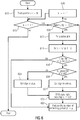
- is a flow chart illustrating an embodiment, depicting the processing steps conducted by a pulse information decoder according to an embodiment, and
- Fig. 7
- is a flow chart illustrating an embodiment, the flow chart depicting the processing steps conducted by a pulse information encoder according to an embodiment.
-
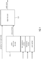
Fig. 1 illustrates an apparatus for decoding an encoded audio signal, wherein one or more tracks are associated with the encoded audio signal, each one of the tracks having a plurality of track positions and a plurality of pulses. - The apparatus comprises a
pulse information decoder 110 and asignal decoder 120. Thepulse information decoder 110 is adapted to decode a plurality of pulse positions. Each one of the pulse positions indicates one of the track positions of one of the tracks to indicate a position of one of the pulses of the track. - The
pulse information decoder 110 is configured to decode the plurality of pulse positions by using a track positions number indicating a total number of the track positions of at least one of the tracks, a total pulses number indicating a total number of the pulses of at least one of the tracks, and one state number. - The
signal decoder 120 is adapted to decode the encoded audio signal by generating a synthesized audio signal using the plurality of pulse positions and a plurality of predictive filter coefficients being associated with the encoded audio signal. - The state number is a number that may have been encoded by an encoder according the embodiments that will be described below. The state number, e.g. comprises information about a plurality of pulse positions in a compact representation, e.g. a representation that requires few bits, and that can be decoded, when the information about the track positions number and the total pulses number is available at the decoder.
- In an embodiment, the track positions number and/or the total pulses number of one or of each track of the audio signal may be available at the decoder, because the track positions number and/or the total pulses number is a static value that doesn't change and is known by the receiver. For example, the track positions number may always be 16 for each track and the total pulses number may always be 4.
- In another embodiment, the track positions number and/or the total pulses number of one or of each track of the audio signal may be explicitly transmitted to the apparatus for decoding, e.g. by the apparatus for encoding.
- In a further embodiment, the decoder may determine the track positions number and/or the total pulses number of one or of each track of the audio signal by analyzing other parameters that do not explicitly state the track positions number and/or the total pulses number, but from which the track positions number and/or the total pulses number can be derived.
- In other embodiments, the decoder may analyze other data available to derive the track positions number and/or the total pulses number of one or of each track of the audio signal.
- In further embodiment, the pulse information decoder may be adapted to also decode, whether a pulse is a positive pulse or a negative pulse.
- In another embodiment, the pulse information decoder may furthermore be adapted to decode pulse information which comprises information about pulses for a plurality of tracks. Pulse information may, for example, be information about the position of the pulses in a track and/or information whether a pulse is a positive pulse or a negative pulse.
-
Fig. 2 illustrates an apparatus for encoding an audio signal, comprising asignal processor 210 and apulse information encoder 220. - The
signal processor 210 is adapted to determine a plurality of predictive filter coefficients being associated with the audio signal, for generating a residual signal based on the audio signal and the plurality of predictive filter coefficients. - The
pulse information encoder 220 is adapted to encode a plurality of pulse positions relating to one or more tracks to encode the audio signal. The one or more tracks are associated with the residual signal generated by thesignal processor 210. Each one of the tracks has a plurality of track positions and a plurality of pulses. Moreover, each one of the pulse positions indicates one of the track positions of one of the tracks to indicate a position of one of the pulses of the track. - The
pulse information encoder 220 is configured to encode the plurality of pulse positions by generating a state number, such that the pulse positions can be decoded only based on the state number, a track positions number indicating a total number of the track positions of at least one of the tracks, and a total pulses number indicating a total number of the pulses of at least one of the tracks. - In the following, the basic concepts of embodiments of the present invention relating to the encoding of the pulse positions and possibly pulse sign (positive pulse or negative pulse) by generating a state number are presented.
- The encoding principles of embodiments of the present invention are based on the finding that if a state enumeration of all possible configurations of k pulses in a track with n track positions is considered, it is sufficient to encode the actual state of the pulses of a track. Encoding such a state by as little bits as possible provides the desirable compact encoding. By this, a concept of state enumeration is presented, wherein each constellation of pulse positions, and possibly also pulse signs, represents one state and each state is uniquely enumerated.
-
Fig. 3 illustrates this for a simple case, where all possible configurations are depicted, when a track having two pulses and three track positions is considered. Two pulses may be located at the same track position. In the example ofFig. 3 , the sign of the pulses (e.g. whether the pulse is positive or negative) is not considered, e.g. in such an example, all pulses may, for example, be considered to be positive. - In
Fig. 3 , all possible states for two undirected pulses located in a track with three track positions (inFig. 3 :track positions Fig. 3 enumerated from 0 to 5) that describe, how the pulses may be distributed in the track. By this, it is sufficient to use a state number in therange 0 to 5 to describe the actual configuration present. For example, if the state number in the example ofFig. 3 has the value (4), and if the decoder is aware of the encoding scheme, the decoder can conclude that state number = 4 means, that the track has one pulse attrack position 0 and another pulse attrack position 2. By this, in the example ofFig. 3 , three bits are sufficient to encode the state number to identify one of the six different states of the example ofFig. 3 . -
Fig. 4 illustrates a case depicting all possible states for one directed pulse located in a track with two track positions (inFig. 4 :track positions 1 and 2). InFig. 4 , the sign of the pulses (e.g. whether the pulse is positive or negative) is considered. There are four different possible states (inFig. 4 enumerated from 0 to 3) that describe, how the pulse may be distributed in track and also its sign (positive or negative). It is sufficient to use a state number in therange 0 to 3 to describe the actual configuration present. For example, if the state number in the example ofFig. 4 has the value (2), and if the decoder is aware of the encoding scheme, the decoder can conclude that state number = 2 means, that the track has one pulse attrack position 1, and that the pulse is a positive pulse. -
Fig. 5 illustrates a still further case, where all possible configurations are depicted, when a track having two pulses and two track positions is considered. Pulses may be located at the same track position. In the example shown inFig. 5 , the sign of the pulses (e.g. whether the pulse is positive or negative) is considered. It is assumed that pulses at the same track position have the same sign (e.g. the tracks at the same track position are either all positive or are all negative). - In
Fig. 5 , all possible states for two signed pulses (e.g. pulses that are either positive or negative) located in a track with two track positions (inFig. 5 :track positions 1 and 2) are illustrated. There are only eight different possible states (inFig. 5 enumerated from 0 to 7) that describe, how the pulses may be distributed in the track. By this, it is sufficient to use a state number in therange 0 to 7 to describe the actual configuration. For example, if the state number in the example ofFig. 5 has the value (3), and if the decoder is aware of the encoding scheme, the decoder can conclude that state number = 3 means, that the track has one pulse attrack position 0 which is positive and another pulse attrack position 1 which is negative. By this, in the example ofFig. 5 , three bits are sufficient to encode the state number to identify one of the eight different states of the example ofFig. 5 . - In ACELP, the residual signal may be encoded by a fixed number of signed pulses. As described above, the pulses may, for example, be distributed in four interlacing tracks, such that
track 0 contains positions mod(n,4)==0, track=1 contains positions mod(n,4)==1, and so on. Each track may have a predefined number of signed unit pulses, which may overlap, but when they overlap, the pulses have the same sign. - By encoding pulses, a mapping from the pulse positions and their signs, into a representation that uses the smallest possible amount of bits should be achieved. In addition, the pulse coding should have a bit consumption that is fixed, that is, any pulse constellation has the same number of bits.
- Each track is first independently encoded and then the states of each track are combined to one number, which represents the state of the whole subframe. This approach gives the mathematically optimal bit-consumption, given that all states have equal probability, and the bit consumption is fixed.
- The concept of state enumeration may also be explained using a compact representation of the different state constellations:
Let the residual signal, which we want to code, be xn . Assuming that four interleaved tracks, e.g. of an algebraic codebook, are considered, then the first track has samples x 0,x 4,x 8...x N-4, the second track has samples x 1 ,x 5 ,x 9 ...x N-3, etc. Suppose, the first track is quantized with one signed unit pulse and that T=8, whereby the length of the track is 2 (T = length (samples) of the residual signal to be encoded). If T=8, and if 4 tracks are used to encode the residual signal, each one of the 4 tracks has 2 track positions. For example, the first track may be considered, that has two track positions x0 and x4. The pulse of the first track can then appear in any of the following constellations:x 0 +1 -1 0 0 x4 0 0 +1 -1 - There are four different states for this configuration.
- Similarly, if there would be two pulses in the first track, the first track having two track positions x0 and x4, the pulses could then be assigned in the following constellations:
x0 +2 -2 +1 +1 -1 -1 0 0 x4 0 0 +1 -1 +1 -1 +2 -2 - Thereby this configuration has 8 states.
- If the length, of the residual signal is extended to T=12, then each of the 4 tracks has 3 track positions. The first track gets one more sample and has now track positions x0, x4 and x8, such that we have:
x0,x4 2 pulses 1 pulse 1 pulse 0 pulses 0 pulses 8 states 4 states 4 states 1 state 1 state x 8 0 +1 -1 +2 -2 - The above table means that there are 8 different states for x0 and x4, if x8 = 0 (x8 has no pulse); 4 different states for x0 and x4, if x8 = 1 (x8 has a positive pulse); 4 different states for x0 and x4, if x8 = -1 (x8 has a negative pulse); 1 state for x0 and x4, if x8 = 2 (x8 has two positive pulses); and 1 state for x0 and x4, if x8 = -2 (x8 has two negative pulses).
- Here, the number of states for the first row has been obtained from the two previous tables. By addition of the number of states in the first row, we see that this configuration has 18 states.
- In the T=12 example, 5 bits are sufficient to encode all the 18 different possible states. The encoder then, for example, selects the state number from the range [0, ..., 17] to specify one of the 18 configurations. If the decoder is aware of the encoding scheme, e.g. if it is aware, which state number represents which configuration, it can decode the pulse positions and pulse signs for a track.
- Below, suitable encoding methods and corresponding decoding methods according to embodiments will be provided. According to embodiments, an apparatus for encoding is provided which is configured to execute one of the encoding methods presented below. Moreover, according to further embodiments, an apparatus for decoding is provided which is configured to execute one of the decoding methods presented below.
- In embodiments, to generate the state number or to decode the state number, the number of possible configurations for N track positions having p pulses may be calculated.
- Pulses may be signed, and a recursive formula may be employed, which calculates the number of states f(p, N) for a track having N track positions and p signed pulses (the pulses may be positive or negative, but pulses at the same track position have the same sign), wherein the recursive formula f(p, N) is defined by:

- The initial conditions are

- Namely, given p pulses, the current position can have qN = 0 to p pulses, whereby the remaining N-1 positions have p - qN pulses. The number of states at the current position and the remaining N-1 positions are multiplied to obtain the number of states with these combinations of pulses and combinations are summed to obtain the total number of states.
- In embodiments, the recursive function may be calculated by an iterative algorithm, wherein the recursion is replaced by iteration.
- As the evaluation of f(p,N) is numerically relatively complex for real time applications, according to some embodiments, a table look-up may be employed to calculate f(p,N). According to some embodiments, the table may have been computed off-line.
- In the following, further concepts are provided for encoding and decoding the state number:
Let f(p,N) denote the number of possible configurations for a track having N track positions and p signed pulses. - The pulse information encoder can now analyze the track: If the first position in the track does not have a pulse, then the remaining N-1 positions have p signed pulses, and to describe this constellation, we need only f(p, N-1) states.
- Otherwise, if the first position has one or more pulses, the pulse information encoder can define that the overall state is greater than f(p, N-1).
- Then, at the pulse information decoder, the pulse information decoder, can, for example, start with the last position and compare the state with a threshold value, e.g. with f(p, N-1). If it is greater, then the pulse information decoder can determine that the last position has at least one pulse. The pulse information decoder can then update the state to obtain an updated state number by subtracting f(p, N-1) from the state and reduce the number of remaining pulses by one.
- Otherwise, if there is no pulse at the last position, the pulse information decoder can reduce the number of remaining positions by one. Repeating this procedure until there are no pulses left, would provide the unsigned positions of pulses.
- To also take the signs of the pulses into account, the pulse information encoder may encode the pulses in the lowest bit of the state. In an alternative embodiment, the pulse information encoder may encode the sign in the highest remaining bit of the state. It is preferred, however, to encode the pulse sign in the lowest bit, as this is easier to handle with respect to integer computations.
- If, in the pulse information decoder, the first pulse of a given position is found, the sign of the pulse is determined by the last bit. Then, the remaining state is shifted one step right to obtain an updated state number.
- In an embodiment, a pulse information decoder is configured to apply the following decoding algorithm. In this decoding algorithm, in a step-by-step approach, for each track position, e.g. one after the other, the state number or the updated state number is compared with a threshold value, e.g. with f(p, k-1).
- According to an embodiment, a pulse information decoder algorithm is provided:
    For each position in track, k=N to 1
           While state s >= f(p,k-1)
                  Put a pulse at k
                  Set s:= s-f(p,k-1)
                  If this is the first pulse at k
                         If lowest bit of s is set, set sign to minus
                         Otherwise, set sign to plus
                         Shift state right one step s := s/2
                  Reduce the number of remaining pulses p : = p-1
Set number of found pulses to zero, p:=0 and state to zero, s:=0
For each position in track, k=1 to N
For each pulse at this position
If the current pulse is the last one on this position
Shift state left one step s:=s*2
If sign is minus, set the lowest bit to one, s := s + 1
Otherwise set the lowest bit to zero (i.e. do nothing)
Update the state s:=s+f(p,k -1)
Increase the number of found pulses p:=p+ 1


 function state = encode(x)
    1. if length of x is 1
           a. if x has no pulses
                   i. state = 0
                  ii. return
           b. else (x has at least one pulse)
                   i. if the pulse(s) in x is positive
                      • state = 0
                      • return
                  ii. else (pulse(s) in x is negative)
                      • state = 1
                      • return
                 iii. end
           c. end
    2. else (that is, when length of x is > 1)
           a. split x into two vectors x1 and x2 of length N1 and N2 respectively
           b. determine state of vector x1 by s1 = encode(x1)
           c. determine state of vector x2 by s2 = encode(x2)
           d. let p be the number of pulses in x and p1 the number of pulses in x1
           e. set n0 = 0
           f. for k from 0 to p1-1
                   i. set n0 := n0 + f(k,N1)*f(p-k,N2)
           g. end
           h. calculate state as s := s1 + f(p1,N1)*s2 + n0
           i. return
    3. end
 function x = decode(s, p, N)
 1. if number of pulses p is 0
        a. return vector x full of zeros
 2. else
        a. if len is 1
                i. if s == 0
                      1. Vector x has p positive pulses at its first position
               ii. else
                      1. Vector x has p negative pulses at its first position
              iii. end
        b. else
                i. Choose partition lengths N1 and N2
               ii. Set n0 := 0 and p1 := 0
              iii. While n0 + f(p1,N1)*f(p-p1) < s
                      1. set p1:= p1+1
                      2. set n0 := n0 + f(p1,N1)*f(p-p1)
              iv. end
               v. set s := s - n0 and p2 := p - p1
              vi. set s1 := s / f(p1,N1) and the remainder into s2
              vii. decode first partition x1 = decode(s1, p1, N1)
             viii. decode second partition x2 = decode(s2, p2, N2)
              ix. merge partitions x1 and x2 in to x
        c. end
 3. end
Claims (7)
- An apparatus for decoding an encoded audio signal, wherein one or more tracks are associated with the encoded audio signal, each one of the tracks having a plurality of track positions and a plurality of pulses, wherein the apparatus comprises:a pulse information decoder (110) for decoding a plurality of pulse positions, wherein each one of the pulse positions indicates one of the track positions of one of the tracks to indicate a position of one of the pulses of the track, and wherein the pulse information decoder (110) is configured to decode the plurality of pulse positions by using a track positions number indicating a total number of the track positions of at least one of the tracks, a total pulses number indicating a total number of the pulses of at least one of the tracks, and one state number; anda signal decoder (120) for decoding the encoded audio signal by generating a synthesized audio signal using the plurality of pulse positions and a plurality of predictive filter coefficients being associated with the encoded audio signal,wherein the pulse information decoder (110) is furthermore adapted to decode a plurality of pulse signs using the track positions number, the total pulses number and the state number, wherein each one of the pulse signs indicates a sign of one of the plurality of pulses, andwherein the signal decoder (120) is adapted to decode the encoded audio signal by generating a synthesized audio signal furthermore using the plurality of pulse signs,wherein the pulse information decoder (110) is adapted to conduct a test comparing the state number or an updated state number with a threshold value,wherein the pulse information decoder (110) is adapted to conduct the test by comparing, whether the state number or an updated state number is greater than, greater than or equal to, smaller than, or smaller than or equal to the threshold value, and wherein the pulse information decoder (110) is furthermore adapted to update the state number or an updated state number depending on the result of the test,wherein the pulse information decoder (110) is configured, to compare, for each track position of one of the plurality of tracks, the state number or the updated state number with the threshold value,wherein the state number indicates a state of an enumeration of all possible states, wherein all possible states indicate all possible configurations of the pulses in one of the one or more tracks having the plurality of track positions.
- An apparatus according to claim 1, wherein the one or more tracks comprise at least a last track and one or more other tracks, and
wherein the pulse information decoder (110) is adapted to generate a first substate number and a second substate number from the state number,
wherein the pulse information decoder (110) is configured to decode a first group of the pulse positions based on the first substate number, and
wherein the pulse information decoder (110) is configured to decode a second group of the pulse positions based on the second substate number,
wherein the second group of the pulse positions only consists of pulse positions indicating track positions of the last track, and
wherein the first group of the pulse positions only consists of pulse positions indicating track positions of the one or more other tracks. - An apparatus according to claim 2, wherein the pulse information decoder is configured to generate the first substate number and the second substate number by dividing the state number by f (p,N) to obtain an integer part and a remainder as a division result, wherein the integer part is the first substate number and wherein the remainder is the second substate number, wherein p indicates for each one of the one or more tracks the number of pulses, and wherein N indicates for each one of the one or more tracks the number of track positions, wherein f(p,N) denotes the number of possible configurations for a track having N track positions and p signed pulses.
- An apparatus for encoding an audio signal, comprising:a signal processor (210) for determining a plurality of predictive filter coefficients being associated with the audio signal, for generating a residual signal based on the audio signal and the plurality of predictive filter coefficients; anda pulse information encoder (220) for encoding a plurality of pulse positions relating to one or more tracks, to encode the audio signal, the one or more tracks being associated with the residual signal, each one of the tracks having a plurality of track positions and a plurality of pulses, wherein each one of the pulse positions indicates one of the track positions of one of the tracks to indicate a position of one of the pulses of the track, wherein the pulse information encoder (220) is configured to encode the plurality of pulse positions by generating a state number, such that the pulse positions can be decoded only based on the state number, a track positions number indicating a total number of the track positions of at least one of the tracks, and a total pulses number indicating a total number of the pulses of at least one of the tracks,wherein the pulse information encoder (220) is adapted to encode a plurality of pulse signs, wherein each one of the pulse signs indicates a sign of one of the plurality of pulses, wherein the pulse information encoder (220) is configured to encode the plurality of pulse signs by generating the state number, such that the pulse signs can be decoded only based on the state number, the track positions number indicating a total number of the track positions of at least one of the tracks, and the total pulses number,wherein the pulse information encoder (220) is configured to add an integer value to an intermediate number for each pulse at a track position for each track position of one of the tracks, to obtain the state number,wherein the state number indicates a state of an enumeration of all possible states, wherein all possible states indicate all possible configurations of the pulses in one of the one or more tracks having the plurality of track positions.
- Method for decoding an encoded audio signal, wherein one or more tracks are associated with the encoded audio signal, each one of the tracks having a plurality of track positions and a plurality of pulses, wherein the method comprises:decoding a plurality of pulse positions, wherein each one of the pulse positions indicates one of the track positions of one of the tracks to indicate a position of one of the pulses of the track, and wherein the plurality of pulse positions are decoded by using a track positions number indicating a total number of the track positions of at least one of the tracks, a total pulses number indicating a total number of the pulses of at least one of the tracks, and one state number; anddecoding the encoded audio signal by generating a synthesized audio signal using the plurality of pulse positions and a plurality of predictive filter coefficients being associated with the encoded audio signal,wherein the method further comprises decoding a plurality of pulse signs using the track positions number, the total pulses number and the state number, wherein each one of the pulse signs indicates a sign of one of the plurality of pulses, andwherein decoding the encoded audio signal is conducted by generating a synthesized audio signal furthermore using the plurality of pulse signs,wherein the method further comprises conducting a test comparing the state number or an updated state number with a threshold value, wherein the test is conducted by comparing, whether the state number or an updated state number is greater than, greater than or equal to, smaller than, or smaller than or equal to the threshold value, wherein the state number or an updated state number is updated depending on the result of the test,wherein the method further comprises comparing, for each track position of one of the plurality of tracks, the state number or the updated state number with the threshold value,wherein the state number indicates a state of an enumeration of all possible states, wherein all possible states indicate all possible configurations of the pulses in one of the one or more tracks having the plurality of track positions.
- Method for encoding an audio signal, comprising:determining a plurality of predictive filter coefficients being associated with the audio signal, for generating a residual signal based on the audio signal and the plurality of predictive filter coefficients; andencoding a plurality of pulse positions relating to one or more tracks, to encode the audio signal, the one or more tracks being associated with the residual signal, each one of the tracks having a plurality of track positions and a plurality of pulses, wherein each one of the pulse positions indicates one of the track positions of one of the tracks to indicate a position of one of the pulses of the track, wherein the plurality of pulse positions are encoded by generating a state number, such that the pulse positions can be decoded only based on the state number, a track positions number indicating a total number of the track positions of at least one of the tracks, and a total pulses number indicating a total number of the pulses of at least one of the tracks,wherein the method further comprises encoding a plurality of pulse signs, wherein each one of the pulse signs indicates a sign of one of the plurality of pulses, wherein encoding the plurality of pulse signs is conducted by generating the state number, such that the pulse signs can be decoded only based on the state number, the track positions number indicating a total number of the track positions of at least one of the tracks, and the total pulses number,wherein the method further comprises adding an integer value to an intermediate number for each pulse at a track position for each track position of one of the tracks, to obtain the state number,wherein the state number indicates a state of an enumeration of all possible states, wherein all possible states indicate all possible configurations of the pulses in one of the one or more tracks having the plurality of track positions.
- A computer program comprising instructions which, when being executed on a computer or signal processor, cause the computer or signal processor to carry out the steps of the method of claim 5 or 6.
Priority Applications (3)
| Application Number | Priority Date | Filing Date | Title |
|---|---|---|---|
| PL17171964T PL3239978T3 (en) | 2011-02-14 | 2012-02-10 | Encoding and decoding of pulse positions of tracks of an audio signal |
| PL18209670T PL3471092T3 (en) | 2011-02-14 | 2012-02-10 | Decoding of pulse positions of tracks of an audio signal |
| EP18209670.1A EP3471092B1 (en) | 2011-02-14 | 2012-02-10 | Decoding of pulse positions of tracks of an audio signal |
Applications Claiming Priority (3)
| Application Number | Priority Date | Filing Date | Title |
|---|---|---|---|
| US201161442632P | 2011-02-14 | 2011-02-14 | |
| PCT/EP2012/052294 WO2012110416A1 (en) | 2011-02-14 | 2012-02-10 | Encoding and decoding of pulse positions of tracks of an audio signal |
| EP12703123.5A EP2676267B1 (en) | 2011-02-14 | 2012-02-10 | Encoding and decoding of pulse positions of tracks of an audio signal |
Related Parent Applications (2)
| Application Number | Title | Priority Date | Filing Date |
|---|---|---|---|
| EP12703123.5A Division-Into EP2676267B1 (en) | 2011-02-14 | 2012-02-10 | Encoding and decoding of pulse positions of tracks of an audio signal |
| EP12703123.5A Division EP2676267B1 (en) | 2011-02-14 | 2012-02-10 | Encoding and decoding of pulse positions of tracks of an audio signal |
Related Child Applications (1)
| Application Number | Title | Priority Date | Filing Date |
|---|---|---|---|
| EP18209670.1A Division EP3471092B1 (en) | 2011-02-14 | 2012-02-10 | Decoding of pulse positions of tracks of an audio signal |
Publications (2)
| Publication Number | Publication Date |
|---|---|
| EP3239978A1 EP3239978A1 (en) | 2017-11-01 |
| EP3239978B1 true EP3239978B1 (en) | 2018-12-26 |
Family
ID=71943601
Family Applications (3)
| Application Number | Title | Priority Date | Filing Date |
|---|---|---|---|
| EP12703123.5A Active EP2676267B1 (en) | 2011-02-14 | 2012-02-10 | Encoding and decoding of pulse positions of tracks of an audio signal |
| EP18209670.1A Active EP3471092B1 (en) | 2011-02-14 | 2012-02-10 | Decoding of pulse positions of tracks of an audio signal |
| EP17171964.4A Active EP3239978B1 (en) | 2011-02-14 | 2012-02-10 | Encoding and decoding of pulse positions of tracks of an audio signal |
Family Applications Before (2)
| Application Number | Title | Priority Date | Filing Date |
|---|---|---|---|
| EP12703123.5A Active EP2676267B1 (en) | 2011-02-14 | 2012-02-10 | Encoding and decoding of pulse positions of tracks of an audio signal |
| EP18209670.1A Active EP3471092B1 (en) | 2011-02-14 | 2012-02-10 | Decoding of pulse positions of tracks of an audio signal |
Country Status (19)
| Country | Link |
|---|---|
| US (1) | US9595263B2 (en) |
| EP (3) | EP2676267B1 (en) |
| JP (1) | JP5800915B2 (en) |
| KR (1) | KR101643450B1 (en) |
| CN (1) | CN103460284B (en) |
| AR (1) | AR085361A1 (en) |
| AU (1) | AU2012217184B2 (en) |
| BR (1) | BR112013020700B1 (en) |
| CA (1) | CA2827156C (en) |
| ES (2) | ES2715191T3 (en) |
| HK (1) | HK1245987B (en) |
| MX (1) | MX2013009345A (en) |
| PL (3) | PL3471092T3 (en) |
| PT (2) | PT3239978T (en) |
| RU (1) | RU2586597C2 (en) |
| SG (1) | SG192747A1 (en) |
| TR (1) | TR201903388T4 (en) |
| WO (1) | WO2012110416A1 (en) |
| ZA (1) | ZA201306841B (en) |
Families Citing this family (10)
| Publication number | Priority date | Publication date | Assignee | Title |
|---|---|---|---|---|
| CN104978970B (en) | 2014-04-08 | 2019-02-12 | 华为技术有限公司 | A kind of processing and generation method, codec and coding/decoding system of noise signal |
| US10553228B2 (en) * | 2015-04-07 | 2020-02-04 | Dolby International Ab | Audio coding with range extension |
| WO2021001358A1 (en) | 2019-07-02 | 2021-01-07 | Dolby International Ab | Methods, apparatus and systems for representation, encoding, and decoding of discrete directivity data |
| US11088784B1 (en) | 2020-12-24 | 2021-08-10 | Aira Technologies, Inc. | Systems and methods for utilizing dynamic codes with neural networks |
| US11575469B2 (en) | 2020-12-28 | 2023-02-07 | Aira Technologies, Inc. | Multi-bit feedback protocol systems and methods |
| US11483109B2 (en) | 2020-12-28 | 2022-10-25 | Aira Technologies, Inc. | Systems and methods for multi-device communication |
| US11368250B1 (en) | 2020-12-28 | 2022-06-21 | Aira Technologies, Inc. | Adaptive payload extraction and retransmission in wireless data communications with error aggregations |
| US11489624B2 (en) | 2021-03-09 | 2022-11-01 | Aira Technologies, Inc. | Error correction in network packets using lookup tables |
| US11489623B2 (en) | 2021-03-15 | 2022-11-01 | Aira Technologies, Inc. | Error correction in network packets |
| US11496242B2 (en) | 2021-03-15 | 2022-11-08 | Aira Technologies, Inc. | Fast cyclic redundancy check: utilizing linearity of cyclic redundancy check for accelerating correction of corrupted network packets |
Family Cites Families (217)
| Publication number | Priority date | Publication date | Assignee | Title |
|---|---|---|---|---|
| ATE477571T1 (en) | 1991-06-11 | 2010-08-15 | Qualcomm Inc | VOCODER WITH VARIABLE BITRATE |
| US5408580A (en) | 1992-09-21 | 1995-04-18 | Aware, Inc. | Audio compression system employing multi-rate signal analysis |
| SE501340C2 (en) | 1993-06-11 | 1995-01-23 | Ericsson Telefon Ab L M | Hiding transmission errors in a speech decoder |
| BE1007617A3 (en) | 1993-10-11 | 1995-08-22 | Philips Electronics Nv | Transmission system using different codeerprincipes. |
| US5657422A (en) | 1994-01-28 | 1997-08-12 | Lucent Technologies Inc. | Voice activity detection driven noise remediator |
| US5784532A (en) | 1994-02-16 | 1998-07-21 | Qualcomm Incorporated | Application specific integrated circuit (ASIC) for performing rapid speech compression in a mobile telephone system |
| US5684920A (en) | 1994-03-17 | 1997-11-04 | Nippon Telegraph And Telephone | Acoustic signal transform coding method and decoding method having a high efficiency envelope flattening method therein |
| US5568588A (en) * | 1994-04-29 | 1996-10-22 | Audiocodes Ltd. | Multi-pulse analysis speech processing System and method |
| KR100419545B1 (en) | 1994-10-06 | 2004-06-04 | 코닌클리케 필립스 일렉트로닉스 엔.브이. | Transmission system using different coding principles |
| SE506379C3 (en) * | 1995-03-22 | 1998-01-19 | Ericsson Telefon Ab L M | Lpc speech encoder with combined excitation |
| US5727119A (en) | 1995-03-27 | 1998-03-10 | Dolby Laboratories Licensing Corporation | Method and apparatus for efficient implementation of single-sideband filter banks providing accurate measures of spectral magnitude and phase |
| JP3317470B2 (en) | 1995-03-28 | 2002-08-26 | 日本電信電話株式会社 | Audio signal encoding method and audio signal decoding method |
| US5659622A (en) | 1995-11-13 | 1997-08-19 | Motorola, Inc. | Method and apparatus for suppressing noise in a communication system |
| US5890106A (en) | 1996-03-19 | 1999-03-30 | Dolby Laboratories Licensing Corporation | Analysis-/synthesis-filtering system with efficient oddly-stacked singleband filter bank using time-domain aliasing cancellation |
| US5848391A (en) | 1996-07-11 | 1998-12-08 | Fraunhofer-Gesellschaft Zur Forderung Der Angewandten Forschung E.V. | Method subband of coding and decoding audio signals using variable length windows |
| JP3259759B2 (en) | 1996-07-22 | 2002-02-25 | 日本電気株式会社 | Audio signal transmission method and audio code decoding system |
| JPH10124092A (en) | 1996-10-23 | 1998-05-15 | Sony Corp | Method and device for encoding speech and method and device for encoding audible signal |
| US5960389A (en) | 1996-11-15 | 1999-09-28 | Nokia Mobile Phones Limited | Methods for generating comfort noise during discontinuous transmission |
| JPH10214100A (en) | 1997-01-31 | 1998-08-11 | Sony Corp | Voice synthesizing method |
| US6134518A (en) | 1997-03-04 | 2000-10-17 | International Business Machines Corporation | Digital audio signal coding using a CELP coder and a transform coder |
| SE512719C2 (en) | 1997-06-10 | 2000-05-02 | Lars Gustaf Liljeryd | A method and apparatus for reducing data flow based on harmonic bandwidth expansion |
| JP3223966B2 (en) | 1997-07-25 | 2001-10-29 | 日本電気株式会社 | Audio encoding / decoding device |
| US6070137A (en) | 1998-01-07 | 2000-05-30 | Ericsson Inc. | Integrated frequency-domain voice coding using an adaptive spectral enhancement filter |
| ES2247741T3 (en) | 1998-01-22 | 2006-03-01 | Deutsche Telekom Ag | SIGNAL CONTROLLED SWITCHING METHOD BETWEEN AUDIO CODING SCHEMES. |
| GB9811019D0 (en) | 1998-05-21 | 1998-07-22 | Univ Surrey | Speech coders |
| US6173257B1 (en) * | 1998-08-24 | 2001-01-09 | Conexant Systems, Inc | Completed fixed codebook for speech encoder |
| US6439967B2 (en) | 1998-09-01 | 2002-08-27 | Micron Technology, Inc. | Microelectronic substrate assembly planarizing machines and methods of mechanical and chemical-mechanical planarization of microelectronic substrate assemblies |
| SE521225C2 (en) * | 1998-09-16 | 2003-10-14 | Ericsson Telefon Ab L M | Method and apparatus for CELP encoding / decoding |
| US7272556B1 (en) | 1998-09-23 | 2007-09-18 | Lucent Technologies Inc. | Scalable and embedded codec for speech and audio signals |
| US7124079B1 (en) | 1998-11-23 | 2006-10-17 | Telefonaktiebolaget Lm Ericsson (Publ) | Speech coding with comfort noise variability feature for increased fidelity |
| FI114833B (en) | 1999-01-08 | 2004-12-31 | Nokia Corp | A method, a speech encoder and a mobile station for generating speech coding frames |
| DE19921122C1 (en) | 1999-05-07 | 2001-01-25 | Fraunhofer Ges Forschung | Method and device for concealing an error in a coded audio signal and method and device for decoding a coded audio signal |
| CN1145928C (en) | 1999-06-07 | 2004-04-14 | 艾利森公司 | Methods and apparatus for generating comfort noise using parametric noise model statistics |
| JP4464484B2 (en) | 1999-06-15 | 2010-05-19 | パナソニック株式会社 | Noise signal encoding apparatus and speech signal encoding apparatus |
| US6236960B1 (en) * | 1999-08-06 | 2001-05-22 | Motorola, Inc. | Factorial packing method and apparatus for information coding |
| US6636829B1 (en) | 1999-09-22 | 2003-10-21 | Mindspeed Technologies, Inc. | Speech communication system and method for handling lost frames |
| ATE341074T1 (en) | 2000-02-29 | 2006-10-15 | Qualcomm Inc | MULTIMODAL MIXED RANGE CLOSED LOOP VOICE ENCODER |
| US6757654B1 (en) | 2000-05-11 | 2004-06-29 | Telefonaktiebolaget Lm Ericsson | Forward error correction in speech coding |
| JP2002118517A (en) | 2000-07-31 | 2002-04-19 | Sony Corp | Apparatus and method for orthogonal transformation, apparatus and method for inverse orthogonal transformation, apparatus and method for transformation encoding as well as apparatus and method for decoding |
| FR2813722B1 (en) | 2000-09-05 | 2003-01-24 | France Telecom | METHOD AND DEVICE FOR CONCEALING ERRORS AND TRANSMISSION SYSTEM COMPRISING SUCH A DEVICE |
| US6847929B2 (en) * | 2000-10-12 | 2005-01-25 | Texas Instruments Incorporated | Algebraic codebook system and method |
| CA2327041A1 (en) * | 2000-11-22 | 2002-05-22 | Voiceage Corporation | A method for indexing pulse positions and signs in algebraic codebooks for efficient coding of wideband signals |
| US6636830B1 (en) | 2000-11-22 | 2003-10-21 | Vialta Inc. | System and method for noise reduction using bi-orthogonal modified discrete cosine transform |
| US20050130321A1 (en) | 2001-04-23 | 2005-06-16 | Nicholson Jeremy K. | Methods for analysis of spectral data and their applications |
| US7136418B2 (en) | 2001-05-03 | 2006-11-14 | University Of Washington | Scalable and perceptually ranked signal coding and decoding |
| KR100464369B1 (en) * | 2001-05-23 | 2005-01-03 | 삼성전자주식회사 | Excitation codebook search method in a speech coding system |
| US20020184009A1 (en) | 2001-05-31 | 2002-12-05 | Heikkinen Ari P. | Method and apparatus for improved voicing determination in speech signals containing high levels of jitter |
| US20030120484A1 (en) | 2001-06-12 | 2003-06-26 | David Wong | Method and system for generating colored comfort noise in the absence of silence insertion description packets |
| DE10129240A1 (en) | 2001-06-18 | 2003-01-02 | Fraunhofer Ges Forschung | Method and device for processing discrete-time audio samples |
| US6879955B2 (en) | 2001-06-29 | 2005-04-12 | Microsoft Corporation | Signal modification based on continuous time warping for low bit rate CELP coding |
| US7711563B2 (en) | 2001-08-17 | 2010-05-04 | Broadcom Corporation | Method and system for frame erasure concealment for predictive speech coding based on extrapolation of speech waveform |
| DE10140507A1 (en) * | 2001-08-17 | 2003-02-27 | Philips Corp Intellectual Pty | Method for the algebraic codebook search of a speech signal coder |
| KR100438175B1 (en) * | 2001-10-23 | 2004-07-01 | 엘지전자 주식회사 | Search method for codebook |
| CA2365203A1 (en) * | 2001-12-14 | 2003-06-14 | Voiceage Corporation | A signal modification method for efficient coding of speech signals |
| US7240001B2 (en) | 2001-12-14 | 2007-07-03 | Microsoft Corporation | Quality improvement techniques in an audio encoder |
| US6934677B2 (en) | 2001-12-14 | 2005-08-23 | Microsoft Corporation | Quantization matrices based on critical band pattern information for digital audio wherein quantization bands differ from critical bands |
| DE10200653B4 (en) | 2002-01-10 | 2004-05-27 | Fraunhofer-Gesellschaft zur Förderung der angewandten Forschung e.V. | Scalable encoder, encoding method, decoder and decoding method for a scaled data stream |
| CA2388439A1 (en) | 2002-05-31 | 2003-11-30 | Voiceage Corporation | A method and device for efficient frame erasure concealment in linear predictive based speech codecs |
| CA2388358A1 (en) * | 2002-05-31 | 2003-11-30 | Voiceage Corporation | A method and device for multi-rate lattice vector quantization |
| CA2388352A1 (en) | 2002-05-31 | 2003-11-30 | Voiceage Corporation | A method and device for frequency-selective pitch enhancement of synthesized speed |
| US7302387B2 (en) * | 2002-06-04 | 2007-11-27 | Texas Instruments Incorporated | Modification of fixed codebook search in G.729 Annex E audio coding |
| US20040010329A1 (en) | 2002-07-09 | 2004-01-15 | Silicon Integrated Systems Corp. | Method for reducing buffer requirements in a digital audio decoder |
| DE10236694A1 (en) | 2002-08-09 | 2004-02-26 | Fraunhofer-Gesellschaft zur Förderung der angewandten Forschung e.V. | Equipment for scalable coding and decoding of spectral values of signal containing audio and/or video information by splitting signal binary spectral values into two partial scaling layers |
| US7299190B2 (en) | 2002-09-04 | 2007-11-20 | Microsoft Corporation | Quantization and inverse quantization for audio |
| US7502743B2 (en) | 2002-09-04 | 2009-03-10 | Microsoft Corporation | Multi-channel audio encoding and decoding with multi-channel transform selection |
| WO2004034379A2 (en) | 2002-10-11 | 2004-04-22 | Nokia Corporation | Methods and devices for source controlled variable bit-rate wideband speech coding |
| US7343283B2 (en) | 2002-10-23 | 2008-03-11 | Motorola, Inc. | Method and apparatus for coding a noise-suppressed audio signal |
| US7363218B2 (en) * | 2002-10-25 | 2008-04-22 | Dilithium Networks Pty. Ltd. | Method and apparatus for fast CELP parameter mapping |
| KR100463419B1 (en) * | 2002-11-11 | 2004-12-23 | 한국전자통신연구원 | Fixed codebook searching method with low complexity, and apparatus thereof |
| KR100463559B1 (en) * | 2002-11-11 | 2004-12-29 | 한국전자통신연구원 | Method for searching codebook in CELP Vocoder using algebraic codebook |
| KR100465316B1 (en) * | 2002-11-18 | 2005-01-13 | 한국전자통신연구원 | Speech encoder and speech encoding method thereof |
| KR20040058855A (en) * | 2002-12-27 | 2004-07-05 | 엘지전자 주식회사 | voice modification device and the method |
| AU2003208517A1 (en) | 2003-03-11 | 2004-09-30 | Nokia Corporation | Switching between coding schemes |
| US7249014B2 (en) * | 2003-03-13 | 2007-07-24 | Intel Corporation | Apparatus, methods and articles incorporating a fast algebraic codebook search technique |
| US20050021338A1 (en) | 2003-03-17 | 2005-01-27 | Dan Graboi | Recognition device and system |
| KR100556831B1 (en) * | 2003-03-25 | 2006-03-10 | 한국전자통신연구원 | Fixed Codebook Searching Method by Global Pulse Replacement |
| WO2004090870A1 (en) * | 2003-04-04 | 2004-10-21 | Kabushiki Kaisha Toshiba | Method and apparatus for encoding or decoding wide-band audio |
| US7318035B2 (en) | 2003-05-08 | 2008-01-08 | Dolby Laboratories Licensing Corporation | Audio coding systems and methods using spectral component coupling and spectral component regeneration |
| DE10321983A1 (en) | 2003-05-15 | 2004-12-09 | Fraunhofer-Gesellschaft zur Förderung der angewandten Forschung e.V. | Device and method for embedding binary useful information in a carrier signal |
| CN100508030C (en) | 2003-06-30 | 2009-07-01 | 皇家飞利浦电子股份有限公司 | Improving quality of decoded audio by adding noise |
| DE10331803A1 (en) | 2003-07-14 | 2005-02-17 | Fraunhofer-Gesellschaft zur Förderung der angewandten Forschung e.V. | Apparatus and method for converting to a transformed representation or for inverse transformation of the transformed representation |
| US7565286B2 (en) | 2003-07-17 | 2009-07-21 | Her Majesty The Queen In Right Of Canada, As Represented By The Minister Of Industry, Through The Communications Research Centre Canada | Method for recovery of lost speech data |
| DE10345995B4 (en) | 2003-10-02 | 2005-07-07 | Fraunhofer-Gesellschaft zur Förderung der angewandten Forschung e.V. | Apparatus and method for processing a signal having a sequence of discrete values |
| DE10345996A1 (en) | 2003-10-02 | 2005-04-28 | Fraunhofer Ges Forschung | Apparatus and method for processing at least two input values |
| US7418396B2 (en) | 2003-10-14 | 2008-08-26 | Broadcom Corporation | Reduced memory implementation technique of filterbank and block switching for real-time audio applications |
| US20050091041A1 (en) | 2003-10-23 | 2005-04-28 | Nokia Corporation | Method and system for speech coding |
| US20050091044A1 (en) | 2003-10-23 | 2005-04-28 | Nokia Corporation | Method and system for pitch contour quantization in audio coding |
| EP1711938A1 (en) | 2004-01-28 | 2006-10-18 | Koninklijke Philips Electronics N.V. | Audio signal decoding using complex-valued data |
| CN1914878B (en) | 2004-02-12 | 2011-04-27 | 诺基亚公司 | Classified media quality of experience |
| DE102004007200B3 (en) | 2004-02-13 | 2005-08-11 | Fraunhofer-Gesellschaft zur Förderung der angewandten Forschung e.V. | Device for audio encoding has device for using filter to obtain scaled, filtered audio value, device for quantizing it to obtain block of quantized, scaled, filtered audio values and device for including information in coded signal |
| CA2457988A1 (en) * | 2004-02-18 | 2005-08-18 | Voiceage Corporation | Methods and devices for audio compression based on acelp/tcx coding and multi-rate lattice vector quantization |
| FI118835B (en) | 2004-02-23 | 2008-03-31 | Nokia Corp | Select end of a coding model |
| FI118834B (en) | 2004-02-23 | 2008-03-31 | Nokia Corp | Classification of audio signals |
| WO2005086138A1 (en) | 2004-03-05 | 2005-09-15 | Matsushita Electric Industrial Co., Ltd. | Error conceal device and error conceal method |
| WO2005096274A1 (en) | 2004-04-01 | 2005-10-13 | Beijing Media Works Co., Ltd | An enhanced audio encoding/decoding device and method |
| GB0408856D0 (en) | 2004-04-21 | 2004-05-26 | Nokia Corp | Signal encoding |
| MXPA06012617A (en) | 2004-05-17 | 2006-12-15 | Nokia Corp | Audio encoding with different coding frame lengths. |
| JP4168976B2 (en) | 2004-05-28 | 2008-10-22 | ソニー株式会社 | Audio signal encoding apparatus and method |
| US7649988B2 (en) | 2004-06-15 | 2010-01-19 | Acoustic Technologies, Inc. | Comfort noise generator using modified Doblinger noise estimate |
| US8160274B2 (en) | 2006-02-07 | 2012-04-17 | Bongiovi Acoustics Llc. | System and method for digital signal processing |
| US7630902B2 (en) | 2004-09-17 | 2009-12-08 | Digital Rise Technology Co., Ltd. | Apparatus and methods for digital audio coding using codebook application ranges |
| KR100656788B1 (en) * | 2004-11-26 | 2006-12-12 | 한국전자통신연구원 | Code vector creation method for bandwidth scalable and broadband vocoder using it |
| TWI253057B (en) | 2004-12-27 | 2006-04-11 | Quanta Comp Inc | Search system and method thereof for searching code-vector of speech signal in speech encoder |
| US7519535B2 (en) | 2005-01-31 | 2009-04-14 | Qualcomm Incorporated | Frame erasure concealment in voice communications |
| US9047860B2 (en) | 2005-01-31 | 2015-06-02 | Skype | Method for concatenating frames in communication system |
| EP1845520A4 (en) | 2005-02-02 | 2011-08-10 | Fujitsu Ltd | Signal processing method and signal processing device |
| US20070147518A1 (en) | 2005-02-18 | 2007-06-28 | Bruno Bessette | Methods and devices for low-frequency emphasis during audio compression based on ACELP/TCX |
| US8155965B2 (en) | 2005-03-11 | 2012-04-10 | Qualcomm Incorporated | Time warping frames inside the vocoder by modifying the residual |
| WO2006107838A1 (en) | 2005-04-01 | 2006-10-12 | Qualcomm Incorporated | Systems, methods, and apparatus for highband time warping |
| WO2006126843A2 (en) | 2005-05-26 | 2006-11-30 | Lg Electronics Inc. | Method and apparatus for decoding audio signal |
| US7707034B2 (en) | 2005-05-31 | 2010-04-27 | Microsoft Corporation | Audio codec post-filter |
| RU2296377C2 (en) | 2005-06-14 | 2007-03-27 | Михаил Николаевич Гусев | Method for analysis and synthesis of speech |
| PL1897085T3 (en) | 2005-06-18 | 2017-10-31 | Nokia Technologies Oy | System and method for adaptive transmission of comfort noise parameters during discontinuous speech transmission |
| FR2888699A1 (en) | 2005-07-13 | 2007-01-19 | France Telecom | HIERACHIC ENCODING / DECODING DEVICE |
| US7610197B2 (en) | 2005-08-31 | 2009-10-27 | Motorola, Inc. | Method and apparatus for comfort noise generation in speech communication systems |
| RU2312405C2 (en) | 2005-09-13 | 2007-12-10 | Михаил Николаевич Гусев | Method for realizing machine estimation of quality of sound signals |
| US20070174047A1 (en) | 2005-10-18 | 2007-07-26 | Anderson Kyle D | Method and apparatus for resynchronizing packetized audio streams |
| US7720677B2 (en) | 2005-11-03 | 2010-05-18 | Coding Technologies Ab | Time warped modified transform coding of audio signals |
| US7536299B2 (en) | 2005-12-19 | 2009-05-19 | Dolby Laboratories Licensing Corporation | Correlating and decorrelating transforms for multiple description coding systems |
| US8255207B2 (en) | 2005-12-28 | 2012-08-28 | Voiceage Corporation | Method and device for efficient frame erasure concealment in speech codecs |
| WO2007080211A1 (en) | 2006-01-09 | 2007-07-19 | Nokia Corporation | Decoding of binaural audio signals |
| CN101371297A (en) | 2006-01-18 | 2009-02-18 | Lg电子株式会社 | Apparatus and method for encoding and decoding signal |
| US8032369B2 (en) | 2006-01-20 | 2011-10-04 | Qualcomm Incorporated | Arbitrary average data rates for variable rate coders |
| US7668304B2 (en) | 2006-01-25 | 2010-02-23 | Avaya Inc. | Display hierarchy of participants during phone call |
| FR2897733A1 (en) | 2006-02-20 | 2007-08-24 | France Telecom | Echo discriminating and attenuating method for hierarchical coder-decoder, involves attenuating echoes based on initial processing in discriminated low energy zone, and inhibiting attenuation of echoes in false alarm zone |
| FR2897977A1 (en) | 2006-02-28 | 2007-08-31 | France Telecom | Coded digital audio signal decoder`s e.g. G.729 decoder, adaptive excitation gain limiting method for e.g. voice over Internet protocol network, involves applying limitation to excitation gain if excitation gain is greater than given value |
| EP1852848A1 (en) | 2006-05-05 | 2007-11-07 | Deutsche Thomson-Brandt GmbH | Method and apparatus for lossless encoding of a source signal using a lossy encoded data stream and a lossless extension data stream |
| US7873511B2 (en) | 2006-06-30 | 2011-01-18 | Fraunhofer-Gesellschaft Zur Foerderung Der Angewandten Forschung E.V. | Audio encoder, audio decoder and audio processor having a dynamically variable warping characteristic |
| JP4810335B2 (en) | 2006-07-06 | 2011-11-09 | 株式会社東芝 | Wideband audio signal encoding apparatus and wideband audio signal decoding apparatus |
| EP2040251B1 (en) | 2006-07-12 | 2019-10-09 | III Holdings 12, LLC | Audio decoding device and audio encoding device |
| WO2008007700A1 (en) | 2006-07-12 | 2008-01-17 | Panasonic Corporation | Sound decoding device, sound encoding device, and lost frame compensation method |
| US7933770B2 (en) | 2006-07-14 | 2011-04-26 | Siemens Audiologische Technik Gmbh | Method and device for coding audio data based on vector quantisation |
| EP2549440B1 (en) | 2006-07-24 | 2017-01-11 | Sony Corporation | A hair motion compositor system and optimization techniques for use in a hair/fur graphics pipeline |
| US7987089B2 (en) | 2006-07-31 | 2011-07-26 | Qualcomm Incorporated | Systems and methods for modifying a zero pad region of a windowed frame of an audio signal |
| DE602007004502D1 (en) | 2006-08-15 | 2010-03-11 | Broadcom Corp | NEUPHASISING THE STATUS OF A DECODER AFTER A PACKAGE LOSS |
| US7877253B2 (en) | 2006-10-06 | 2011-01-25 | Qualcomm Incorporated | Systems, methods, and apparatus for frame erasure recovery |
| US8126721B2 (en) | 2006-10-18 | 2012-02-28 | Fraunhofer-Gesellschaft Zur Foerderung Der Angewandten Forschung E.V. | Encoding an information signal |
| DE102006049154B4 (en) | 2006-10-18 | 2009-07-09 | Fraunhofer-Gesellschaft zur Förderung der angewandten Forschung e.V. | Coding of an information signal |
| US8417532B2 (en) | 2006-10-18 | 2013-04-09 | Fraunhofer-Gesellschaft Zur Foerderung Der Angewandten Forschung E.V. | Encoding an information signal |
| US8036903B2 (en) | 2006-10-18 | 2011-10-11 | Fraunhofer-Gesellschaft Zur Foerderung Der Angewandten Forschung E.V. | Analysis filterbank, synthesis filterbank, encoder, de-coder, mixer and conferencing system |
| US8041578B2 (en) | 2006-10-18 | 2011-10-18 | Fraunhofer-Gesellschaft Zur Foerderung Der Angewandten Forschung E.V. | Encoding an information signal |
| US8452605B2 (en) | 2006-10-25 | 2013-05-28 | Fraunhofer-Gesellschaft Zur Foerderung Der Angewandten Forschung E.V. | Apparatus and method for generating audio subband values and apparatus and method for generating time-domain audio samples |
| DE102006051673A1 (en) | 2006-11-02 | 2008-05-15 | Fraunhofer-Gesellschaft zur Förderung der angewandten Forschung e.V. | Apparatus and method for reworking spectral values and encoders and decoders for audio signals |
| CN102395033B (en) | 2006-12-12 | 2014-08-27 | 弗劳恩霍夫应用研究促进协会 | Encoder, decoder and methods for encoding and decoding data segments representing a time-domain data stream |
| FR2911228A1 (en) | 2007-01-05 | 2008-07-11 | France Telecom | TRANSFORMED CODING USING WINDOW WEATHER WINDOWS. |
| KR101379263B1 (en) | 2007-01-12 | 2014-03-28 | 삼성전자주식회사 | Method and apparatus for decoding bandwidth extension |
| FR2911426A1 (en) | 2007-01-15 | 2008-07-18 | France Telecom | MODIFICATION OF A SPEECH SIGNAL |
| US7873064B1 (en) | 2007-02-12 | 2011-01-18 | Marvell International Ltd. | Adaptive jitter buffer-packet loss concealment |
| WO2008108083A1 (en) | 2007-03-02 | 2008-09-12 | Panasonic Corporation | Voice encoding device and voice encoding method |
| JP4708446B2 (en) | 2007-03-02 | 2011-06-22 | パナソニック株式会社 | Encoding device, decoding device and methods thereof |
| SG179433A1 (en) | 2007-03-02 | 2012-04-27 | Panasonic Corp | Encoding device and encoding method |
| DE102007063635A1 (en) | 2007-03-22 | 2009-04-02 | Fraunhofer-Gesellschaft zur Förderung der angewandten Forschung e.V. | A method for temporally segmenting a video into video sequences and selecting keyframes for retrieving image content including subshot detection |
| JP2008261904A (en) | 2007-04-10 | 2008-10-30 | Matsushita Electric Ind Co Ltd | Encoding device, decoding device, encoding method and decoding method |
| US8630863B2 (en) | 2007-04-24 | 2014-01-14 | Samsung Electronics Co., Ltd. | Method and apparatus for encoding and decoding audio/speech signal |
| CN101388210B (en) * | 2007-09-15 | 2012-03-07 | 华为技术有限公司 | Coding and decoding method, coder and decoder |
| ES2529292T3 (en) * | 2007-04-29 | 2015-02-18 | Huawei Technologies Co., Ltd. | Encoding and decoding method |
| EP2165328B1 (en) | 2007-06-11 | 2018-01-17 | Fraunhofer-Gesellschaft zur Förderung der angewandten Forschung e.V. | Encoding and decoding of an audio signal having an impulse-like portion and a stationary portion |
| US9653088B2 (en) | 2007-06-13 | 2017-05-16 | Qualcomm Incorporated | Systems, methods, and apparatus for signal encoding using pitch-regularizing and non-pitch-regularizing coding |
| KR101513028B1 (en) | 2007-07-02 | 2015-04-17 | 엘지전자 주식회사 | broadcasting receiver and method of processing broadcast signal |
| US8185381B2 (en) | 2007-07-19 | 2012-05-22 | Qualcomm Incorporated | Unified filter bank for performing signal conversions |
| CN101110214B (en) | 2007-08-10 | 2011-08-17 | 北京理工大学 | Speech coding method based on multiple description lattice type vector quantization technology |
| US8428957B2 (en) | 2007-08-24 | 2013-04-23 | Qualcomm Incorporated | Spectral noise shaping in audio coding based on spectral dynamics in frequency sub-bands |
| WO2009029032A2 (en) | 2007-08-27 | 2009-03-05 | Telefonaktiebolaget Lm Ericsson (Publ) | Low-complexity spectral analysis/synthesis using selectable time resolution |
| JP4886715B2 (en) | 2007-08-28 | 2012-02-29 | 日本電信電話株式会社 | Steady rate calculation device, noise level estimation device, noise suppression device, method thereof, program, and recording medium |
| US8566106B2 (en) | 2007-09-11 | 2013-10-22 | Voiceage Corporation | Method and device for fast algebraic codebook search in speech and audio coding |
| CN100524462C (en) | 2007-09-15 | 2009-08-05 | 华为技术有限公司 | Method and apparatus for concealing frame error of high belt signal |
| US8576096B2 (en) | 2007-10-11 | 2013-11-05 | Motorola Mobility Llc | Apparatus and method for low complexity combinatorial coding of signals |
| KR101373004B1 (en) | 2007-10-30 | 2014-03-26 | 삼성전자주식회사 | Apparatus and method for encoding and decoding high frequency signal |
| CN101425292B (en) | 2007-11-02 | 2013-01-02 | 华为技术有限公司 | Decoding method and device for audio signal |
| DE102007055830A1 (en) | 2007-12-17 | 2009-06-18 | Zf Friedrichshafen Ag | Method and device for operating a hybrid drive of a vehicle |
| CN101483043A (en) * | 2008-01-07 | 2009-07-15 | 中兴通讯股份有限公司 | Code book index encoding method based on classification, permutation and combination |
| CN101488344B (en) | 2008-01-16 | 2011-09-21 | 华为技术有限公司 | Quantitative noise leakage control method and apparatus |
| DE102008015702B4 (en) | 2008-01-31 | 2010-03-11 | Fraunhofer-Gesellschaft zur Förderung der angewandten Forschung e.V. | Apparatus and method for bandwidth expansion of an audio signal |
| CN102789782B (en) | 2008-03-04 | 2015-10-14 | 弗劳恩霍夫应用研究促进协会 | Input traffic is mixed and therefrom produces output stream |
| US8000487B2 (en) | 2008-03-06 | 2011-08-16 | Starkey Laboratories, Inc. | Frequency translation by high-frequency spectral envelope warping in hearing assistance devices |
| FR2929466A1 (en) | 2008-03-28 | 2009-10-02 | France Telecom | DISSIMULATION OF TRANSMISSION ERROR IN A DIGITAL SIGNAL IN A HIERARCHICAL DECODING STRUCTURE |
| EP2107556A1 (en) | 2008-04-04 | 2009-10-07 | Fraunhofer-Gesellschaft zur Förderung der angewandten Forschung e.V. | Audio transform coding using pitch correction |
| US8879643B2 (en) | 2008-04-15 | 2014-11-04 | Qualcomm Incorporated | Data substitution scheme for oversampled data |
| US8768690B2 (en) | 2008-06-20 | 2014-07-01 | Qualcomm Incorporated | Coding scheme selection for low-bit-rate applications |
| ES2654433T3 (en) * | 2008-07-11 | 2018-02-13 | Fraunhofer-Gesellschaft zur Förderung der angewandten Forschung e.V. | Audio signal encoder, method for encoding an audio signal and computer program |
| EP2144230A1 (en) | 2008-07-11 | 2010-01-13 | Fraunhofer-Gesellschaft zur Förderung der angewandten Forschung e.V. | Low bitrate audio encoding/decoding scheme having cascaded switches |
| JP5551695B2 (en) | 2008-07-11 | 2014-07-16 | フラウンホッファー−ゲゼルシャフト ツァ フェルダールング デァ アンゲヴァンテン フォアシュンク エー.ファオ | Speech encoder, speech decoder, speech encoding method, speech decoding method, and computer program |
| ES2401487T3 (en) | 2008-07-11 | 2013-04-22 | Fraunhofer-Gesellschaft zur Förderung der angewandten Forschung e.V. | Apparatus and procedure for encoding / decoding an audio signal using a foreign signal generation switching scheme |
| MY154452A (en) | 2008-07-11 | 2015-06-15 | Fraunhofer Ges Forschung | An apparatus and a method for decoding an encoded audio signal |
| MX2011000375A (en) | 2008-07-11 | 2011-05-19 | Fraunhofer Ges Forschung | Audio encoder and decoder for encoding and decoding frames of sampled audio signal. |
| ES2683077T3 (en) | 2008-07-11 | 2018-09-24 | Fraunhofer-Gesellschaft zur Förderung der angewandten Forschung e.V. | Audio encoder and decoder for encoding and decoding frames of a sampled audio signal |
| US8352279B2 (en) | 2008-09-06 | 2013-01-08 | Huawei Technologies Co., Ltd. | Efficient temporal envelope coding approach by prediction between low band signal and high band signal |
| US8380498B2 (en) | 2008-09-06 | 2013-02-19 | GH Innovation, Inc. | Temporal envelope coding of energy attack signal by using attack point location |
| WO2010031049A1 (en) | 2008-09-15 | 2010-03-18 | GH Innovation, Inc. | Improving celp post-processing for music signals |
| US8798776B2 (en) | 2008-09-30 | 2014-08-05 | Dolby International Ab | Transcoding of audio metadata |
| DE102008042579B4 (en) | 2008-10-02 | 2020-07-23 | Robert Bosch Gmbh | Procedure for masking errors in the event of incorrect transmission of voice data |
| EP3640941A1 (en) | 2008-10-08 | 2020-04-22 | Fraunhofer Gesellschaft zur Förderung der Angewand | Multi-resolution switched audio encoding/decoding scheme |
| KR101315617B1 (en) | 2008-11-26 | 2013-10-08 | 광운대학교 산학협력단 | Unified speech/audio coder(usac) processing windows sequence based mode switching |
| CN101770775B (en) | 2008-12-31 | 2011-06-22 | 华为技术有限公司 | Signal processing method and device |
| KR101256808B1 (en) | 2009-01-16 | 2013-04-22 | 돌비 인터네셔널 에이비 | Cross product enhanced harmonic transposition |
| US8457975B2 (en) | 2009-01-28 | 2013-06-04 | Fraunhofer-Gesellschaft Zur Foerderung Der Angewandten Forschung E.V. | Audio decoder, audio encoder, methods for decoding and encoding an audio signal and computer program |
| MX2011007925A (en) | 2009-01-28 | 2011-08-17 | Dten Forschung E V Fraunhofer Ges Zur Foeerderung Der Angewan | Audio coding. |
| EP2214165A3 (en) | 2009-01-30 | 2010-09-15 | Fraunhofer-Gesellschaft zur Förderung der angewandten Forschung e.V. | Apparatus, method and computer program for manipulating an audio signal comprising a transient event |
| WO2010093224A2 (en) | 2009-02-16 | 2010-08-19 | 한국전자통신연구원 | Encoding/decoding method for audio signals using adaptive sine wave pulse coding and apparatus thereof |
| PL2234103T3 (en) | 2009-03-26 | 2012-02-29 | Fraunhofer Ges Forschung | Device and method for manipulating an audio signal |
| KR20100115215A (en) | 2009-04-17 | 2010-10-27 | 삼성전자주식회사 | Apparatus and method for audio encoding/decoding according to variable bit rate |
| US8725503B2 (en) | 2009-06-23 | 2014-05-13 | Voiceage Corporation | Forward time-domain aliasing cancellation with application in weighted or original signal domain |
| JP5267362B2 (en) | 2009-07-03 | 2013-08-21 | 富士通株式会社 | Audio encoding apparatus, audio encoding method, audio encoding computer program, and video transmission apparatus |
| CN101958119B (en) | 2009-07-16 | 2012-02-29 | 中兴通讯股份有限公司 | Audio-frequency drop-frame compensator and compensation method for modified discrete cosine transform domain |
| US8635357B2 (en) | 2009-09-08 | 2014-01-21 | Google Inc. | Dynamic selection of parameter sets for transcoding media data |
| MY167980A (en) | 2009-10-20 | 2018-10-09 | Fraunhofer Ges Forschung | Multi- mode audio codec and celp coding adapted therefore |
| MY162251A (en) | 2009-10-20 | 2017-05-31 | Fraunhofer Ges Forschung | Audio signal encoder,audio signal decoder,method for providing an encoded representation of an audio content,method for providing a decoded representation of an audio content and computer program for use in low delay applications |
| AU2010309838B2 (en) | 2009-10-20 | 2014-05-08 | Dolby International Ab | Audio signal encoder, audio signal decoder, method for encoding or decoding an audio signal using an aliasing-cancellation |
| CN102081927B (en) | 2009-11-27 | 2012-07-18 | 中兴通讯股份有限公司 | Layering audio coding and decoding method and system |
| US8428936B2 (en) | 2010-03-05 | 2013-04-23 | Motorola Mobility Llc | Decoder for audio signal including generic audio and speech frames |
| US8423355B2 (en) | 2010-03-05 | 2013-04-16 | Motorola Mobility Llc | Encoder for audio signal including generic audio and speech frames |
| US8793126B2 (en) | 2010-04-14 | 2014-07-29 | Huawei Technologies Co., Ltd. | Time/frequency two dimension post-processing |
| WO2011147950A1 (en) | 2010-05-28 | 2011-12-01 | Fraunhofer-Gesellschaft zur Förderung der angewandten Forschung e.V. | Low-delay unified speech and audio codec |
| FR2963254B1 (en) | 2010-07-27 | 2012-08-24 | Maurice Guerin | DEVICE AND METHOD FOR WASHING INTERNAL SURFACES WITH AN ENCLOSURE |
| RU2560788C2 (en) | 2011-02-14 | 2015-08-20 | Фраунхофер-Гезелльшафт Цур Фердерунг Дер Ангевандтен Форшунг Е.Ф. | Device and method for processing of decoded audio signal in spectral band |
| MX2013009305A (en) | 2011-02-14 | 2013-10-03 | Fraunhofer Ges Forschung | Noise generation in audio codecs. |
| WO2013075753A1 (en) | 2011-11-25 | 2013-05-30 | Huawei Technologies Co., Ltd. | An apparatus and a method for encoding an input signal |
-
2012
- 2012-02-10 JP JP2013553882A patent/JP5800915B2/en active Active
- 2012-02-10 RU RU2013142068/08A patent/RU2586597C2/en active
- 2012-02-10 PT PT17171964T patent/PT3239978T/en unknown
- 2012-02-10 EP EP12703123.5A patent/EP2676267B1/en active Active
- 2012-02-10 EP EP18209670.1A patent/EP3471092B1/en active Active
- 2012-02-10 ES ES17171964T patent/ES2715191T3/en active Active
- 2012-02-10 EP EP17171964.4A patent/EP3239978B1/en active Active
- 2012-02-10 ES ES12703123.5T patent/ES2639646T3/en active Active
- 2012-02-10 WO PCT/EP2012/052294 patent/WO2012110416A1/en active Application Filing
- 2012-02-10 AU AU2012217184A patent/AU2012217184B2/en active Active
- 2012-02-10 MX MX2013009345A patent/MX2013009345A/en active IP Right Grant
- 2012-02-10 SG SG2013061379A patent/SG192747A1/en unknown
- 2012-02-10 PL PL18209670T patent/PL3471092T3/en unknown
- 2012-02-10 KR KR1020137024213A patent/KR101643450B1/en active IP Right Grant
- 2012-02-10 PL PL17171964T patent/PL3239978T3/en unknown
- 2012-02-10 AR ARP120100443A patent/AR085361A1/en active IP Right Grant
- 2012-02-10 TR TR2019/03388T patent/TR201903388T4/en unknown
- 2012-02-10 CA CA2827156A patent/CA2827156C/en active Active
- 2012-02-10 PT PT127031235T patent/PT2676267T/en unknown
- 2012-02-10 CN CN201280016442.4A patent/CN103460284B/en active Active
- 2012-02-10 PL PL12703123T patent/PL2676267T3/en unknown
- 2012-02-10 BR BR112013020700-0A patent/BR112013020700B1/en active IP Right Grant
-
2013
- 2013-08-14 US US13/966,635 patent/US9595263B2/en active Active
- 2013-09-11 ZA ZA2013/06841A patent/ZA201306841B/en unknown
-
2018
- 2018-04-24 HK HK18105291.5A patent/HK1245987B/en unknown
Non-Patent Citations (1)
| Title |
|---|
| None * |
Also Published As
Similar Documents
| Publication | Publication Date | Title |
|---|---|---|
| EP3239978B1 (en) | Encoding and decoding of pulse positions of tracks of an audio signal | |
| RU2710909C1 (en) | Audio encoder and audio decoder | |
| EP2932502B1 (en) | Method and apparatus for compressing and decompressing a higher order ambisonics representation for a sound field | |
| TWI488176B (en) | Encoding and decoding of pulse positions of tracks of an audio signal | |
| EP1869774B1 (en) | Adaptive grouping of parameters for enhanced coding efficiency | |
| KR20100083126A (en) | Encoding and/or decoding digital content | |
| EP3367381B1 (en) | Audio quantizing by reduced-complexity vector indexing | |
| EP3074970B1 (en) | Audio encoder and decoder | |
| EP3467824B1 (en) | Method and system for inter-channel coding | |
| CN101197133A (en) | Decoding method and device | |
| RU2810027C2 (en) | Audio encoder and audio decoder | |
| US20060136202A1 (en) | Quantization of excitation vector | |
| US7330136B2 (en) | Method and device to provide arithmetic decoding of scalable BSAC audio data | |
| ES2821725T3 (en) | Encoding and decoding of pulse positions of tracks of an audio signal | |
| EP3285253A1 (en) | Coding device, communication processing device, and coding method |
Legal Events
| Date | Code | Title | Description |
|---|---|---|---|
| PUAI | Public reference made under article 153(3) epc to a published international application that has entered the european phase |
Free format text: ORIGINAL CODE: 0009012 |
|
| STAA | Information on the status of an ep patent application or granted ep patent |
Free format text: STATUS: THE APPLICATION HAS BEEN PUBLISHED |
|
| AC | Divisional application: reference to earlier application |
Ref document number: 2676267 Country of ref document: EP Kind code of ref document: P |
|
| AK | Designated contracting states |
Kind code of ref document: A1 Designated state(s): AL AT BE BG CH CY CZ DE DK EE ES FI FR GB GR HR HU IE IS IT LI LT LU LV MC MK MT NL NO PL PT RO RS SE SI SK SM TR |
|
| STAA | Information on the status of an ep patent application or granted ep patent |
Free format text: STATUS: REQUEST FOR EXAMINATION WAS MADE |
|
| 17P | Request for examination filed |
Effective date: 20180502 |
|
| RBV | Designated contracting states (corrected) |
Designated state(s): AL AT BE BG CH CY CZ DE DK EE ES FI FR GB GR HR HU IE IS IT LI LT LU LV MC MK MT NL NO PL PT RO RS SE SI SK SM TR |
|
| GRAP | Despatch of communication of intention to grant a patent |
Free format text: ORIGINAL CODE: EPIDOSNIGR1 |
|
| RIC1 | Information provided on ipc code assigned before grant |
Ipc: G10L 19/22 20130101ALI20180531BHEP Ipc: G10L 19/03 20130101ALI20180531BHEP Ipc: G10L 19/025 20130101ALN20180531BHEP Ipc: G10L 19/02 20130101ALN20180531BHEP Ipc: G10L 19/107 20130101ALN20180531BHEP Ipc: G10L 19/26 20130101ALN20180531BHEP Ipc: G10L 21/0216 20130101ALI20180531BHEP Ipc: G10L 19/012 20130101AFI20180531BHEP Ipc: G10L 19/04 20130101ALN20180531BHEP Ipc: G10L 25/78 20130101ALI20180531BHEP Ipc: G10L 25/06 20130101ALN20180531BHEP |
|
| STAA | Information on the status of an ep patent application or granted ep patent |
Free format text: STATUS: GRANT OF PATENT IS INTENDED |
|
| INTG | Intention to grant announced |
Effective date: 20180705 |
|
| REG | Reference to a national code |
Ref country code: HK Ref legal event code: DE Ref document number: 1245987 Country of ref document: HK |
|
| GRAS | Grant fee paid |
Free format text: ORIGINAL CODE: EPIDOSNIGR3 |
|
| GRAA | (expected) grant |
Free format text: ORIGINAL CODE: 0009210 |
|
| STAA | Information on the status of an ep patent application or granted ep patent |
Free format text: STATUS: THE PATENT HAS BEEN GRANTED |
|
| AC | Divisional application: reference to earlier application |
Ref document number: 2676267 Country of ref document: EP Kind code of ref document: P |
|
| AK | Designated contracting states |
Kind code of ref document: B1 Designated state(s): AL AT BE BG CH CY CZ DE DK EE ES FI FR GB GR HR HU IE IS IT LI LT LU LV MC MK MT NL NO PL PT RO RS SE SI SK SM TR |
|
| REG | Reference to a national code |
Ref country code: GB Ref legal event code: FG4D |
|
| REG | Reference to a national code |
Ref country code: CH Ref legal event code: EP |
|
| REG | Reference to a national code |
Ref country code: AT Ref legal event code: REF Ref document number: 1082524 Country of ref document: AT Kind code of ref document: T Effective date: 20190115 |
|
| REG | Reference to a national code |
Ref country code: DE Ref legal event code: R096 Ref document number: 602012055333 Country of ref document: DE |
|
| REG | Reference to a national code |
Ref country code: IE Ref legal event code: FG4D |
|
| REG | Reference to a national code |
Ref country code: PT Ref legal event code: SC4A Ref document number: 3239978 Country of ref document: PT Date of ref document: 20190402 Kind code of ref document: T Free format text: AVAILABILITY OF NATIONAL TRANSLATION Effective date: 20190325 |
|
| REG | Reference to a national code |
Ref country code: SE Ref legal event code: TRGR |
|
| REG | Reference to a national code |
Ref country code: NL Ref legal event code: FP |
|
| PG25 | Lapsed in a contracting state [announced via postgrant information from national office to epo] |
Ref country code: HR Free format text: LAPSE BECAUSE OF FAILURE TO SUBMIT A TRANSLATION OF THE DESCRIPTION OR TO PAY THE FEE WITHIN THE PRESCRIBED TIME-LIMIT Effective date: 20181226 Ref country code: LT Free format text: LAPSE BECAUSE OF FAILURE TO SUBMIT A TRANSLATION OF THE DESCRIPTION OR TO PAY THE FEE WITHIN THE PRESCRIBED TIME-LIMIT Effective date: 20181226 Ref country code: LV Free format text: LAPSE BECAUSE OF FAILURE TO SUBMIT A TRANSLATION OF THE DESCRIPTION OR TO PAY THE FEE WITHIN THE PRESCRIBED TIME-LIMIT Effective date: 20181226 Ref country code: NO Free format text: LAPSE BECAUSE OF FAILURE TO SUBMIT A TRANSLATION OF THE DESCRIPTION OR TO PAY THE FEE WITHIN THE PRESCRIBED TIME-LIMIT Effective date: 20190326 Ref country code: BG Free format text: LAPSE BECAUSE OF FAILURE TO SUBMIT A TRANSLATION OF THE DESCRIPTION OR TO PAY THE FEE WITHIN THE PRESCRIBED TIME-LIMIT Effective date: 20190326 |
|
| REG | Reference to a national code |
Ref country code: LT Ref legal event code: MG4D |
|
| PG25 | Lapsed in a contracting state [announced via postgrant information from national office to epo] |
Ref country code: AL Free format text: LAPSE BECAUSE OF FAILURE TO SUBMIT A TRANSLATION OF THE DESCRIPTION OR TO PAY THE FEE WITHIN THE PRESCRIBED TIME-LIMIT Effective date: 20181226 Ref country code: RS Free format text: LAPSE BECAUSE OF FAILURE TO SUBMIT A TRANSLATION OF THE DESCRIPTION OR TO PAY THE FEE WITHIN THE PRESCRIBED TIME-LIMIT Effective date: 20181226 Ref country code: GR Free format text: LAPSE BECAUSE OF FAILURE TO SUBMIT A TRANSLATION OF THE DESCRIPTION OR TO PAY THE FEE WITHIN THE PRESCRIBED TIME-LIMIT Effective date: 20190327 |
|
| REG | Reference to a national code |
Ref country code: ES Ref legal event code: FG2A Ref document number: 2715191 Country of ref document: ES Kind code of ref document: T3 Effective date: 20190603 |
|
| REG | Reference to a national code |
Ref country code: AT Ref legal event code: MK05 Ref document number: 1082524 Country of ref document: AT Kind code of ref document: T Effective date: 20181226 |
|
| PG25 | Lapsed in a contracting state [announced via postgrant information from national office to epo] |
Ref country code: CZ Free format text: LAPSE BECAUSE OF FAILURE TO SUBMIT A TRANSLATION OF THE DESCRIPTION OR TO PAY THE FEE WITHIN THE PRESCRIBED TIME-LIMIT Effective date: 20181226 |
|
| PG25 | Lapsed in a contracting state [announced via postgrant information from national office to epo] |
Ref country code: IS Free format text: LAPSE BECAUSE OF FAILURE TO SUBMIT A TRANSLATION OF THE DESCRIPTION OR TO PAY THE FEE WITHIN THE PRESCRIBED TIME-LIMIT Effective date: 20190426 Ref country code: SK Free format text: LAPSE BECAUSE OF FAILURE TO SUBMIT A TRANSLATION OF THE DESCRIPTION OR TO PAY THE FEE WITHIN THE PRESCRIBED TIME-LIMIT Effective date: 20181226 Ref country code: RO Free format text: LAPSE BECAUSE OF FAILURE TO SUBMIT A TRANSLATION OF THE DESCRIPTION OR TO PAY THE FEE WITHIN THE PRESCRIBED TIME-LIMIT Effective date: 20181226 Ref country code: EE Free format text: LAPSE BECAUSE OF FAILURE TO SUBMIT A TRANSLATION OF THE DESCRIPTION OR TO PAY THE FEE WITHIN THE PRESCRIBED TIME-LIMIT Effective date: 20181226 Ref country code: SM Free format text: LAPSE BECAUSE OF FAILURE TO SUBMIT A TRANSLATION OF THE DESCRIPTION OR TO PAY THE FEE WITHIN THE PRESCRIBED TIME-LIMIT Effective date: 20181226 |
|
| REG | Reference to a national code |
Ref country code: DE Ref legal event code: R097 Ref document number: 602012055333 Country of ref document: DE |
|
| REG | Reference to a national code |
Ref country code: CH Ref legal event code: PL |
|
| PG25 | Lapsed in a contracting state [announced via postgrant information from national office to epo] |
Ref country code: DK Free format text: LAPSE BECAUSE OF FAILURE TO SUBMIT A TRANSLATION OF THE DESCRIPTION OR TO PAY THE FEE WITHIN THE PRESCRIBED TIME-LIMIT Effective date: 20181226 Ref country code: LU Free format text: LAPSE BECAUSE OF NON-PAYMENT OF DUE FEES Effective date: 20190210 Ref country code: MC Free format text: LAPSE BECAUSE OF FAILURE TO SUBMIT A TRANSLATION OF THE DESCRIPTION OR TO PAY THE FEE WITHIN THE PRESCRIBED TIME-LIMIT Effective date: 20181226 Ref country code: AT Free format text: LAPSE BECAUSE OF FAILURE TO SUBMIT A TRANSLATION OF THE DESCRIPTION OR TO PAY THE FEE WITHIN THE PRESCRIBED TIME-LIMIT Effective date: 20181226 |
|
| PLBE | No opposition filed within time limit |
Free format text: ORIGINAL CODE: 0009261 |
|
| STAA | Information on the status of an ep patent application or granted ep patent |
Free format text: STATUS: NO OPPOSITION FILED WITHIN TIME LIMIT |
|
| REG | Reference to a national code |
Ref country code: IE Ref legal event code: MM4A |
|
| 26N | No opposition filed |
Effective date: 20190927 |
|
| PG25 | Lapsed in a contracting state [announced via postgrant information from national office to epo] |
Ref country code: CH Free format text: LAPSE BECAUSE OF NON-PAYMENT OF DUE FEES Effective date: 20190228 Ref country code: LI Free format text: LAPSE BECAUSE OF NON-PAYMENT OF DUE FEES Effective date: 20190228 |
|
| PG25 | Lapsed in a contracting state [announced via postgrant information from national office to epo] |
Ref country code: IE Free format text: LAPSE BECAUSE OF NON-PAYMENT OF DUE FEES Effective date: 20190210 |
|
| PG25 | Lapsed in a contracting state [announced via postgrant information from national office to epo] |
Ref country code: SI Free format text: LAPSE BECAUSE OF FAILURE TO SUBMIT A TRANSLATION OF THE DESCRIPTION OR TO PAY THE FEE WITHIN THE PRESCRIBED TIME-LIMIT Effective date: 20181226 |
|
| PG25 | Lapsed in a contracting state [announced via postgrant information from national office to epo] |
Ref country code: MT Free format text: LAPSE BECAUSE OF NON-PAYMENT OF DUE FEES Effective date: 20190210 |
|
| PG25 | Lapsed in a contracting state [announced via postgrant information from national office to epo] |
Ref country code: CY Free format text: LAPSE BECAUSE OF FAILURE TO SUBMIT A TRANSLATION OF THE DESCRIPTION OR TO PAY THE FEE WITHIN THE PRESCRIBED TIME-LIMIT Effective date: 20181226 |
|
| PG25 | Lapsed in a contracting state [announced via postgrant information from national office to epo] |
Ref country code: HU Free format text: LAPSE BECAUSE OF FAILURE TO SUBMIT A TRANSLATION OF THE DESCRIPTION OR TO PAY THE FEE WITHIN THE PRESCRIBED TIME-LIMIT; INVALID AB INITIO Effective date: 20120210 |
|
| PG25 | Lapsed in a contracting state [announced via postgrant information from national office to epo] |
Ref country code: MK Free format text: LAPSE BECAUSE OF FAILURE TO SUBMIT A TRANSLATION OF THE DESCRIPTION OR TO PAY THE FEE WITHIN THE PRESCRIBED TIME-LIMIT Effective date: 20181226 |
|
| PGFP | Annual fee paid to national office [announced via postgrant information from national office to epo] |
Ref country code: FR Payment date: 20230217 Year of fee payment: 12 |
|
| PGFP | Annual fee paid to national office [announced via postgrant information from national office to epo] |
Ref country code: TR Payment date: 20230209 Year of fee payment: 12 Ref country code: SE Payment date: 20230220 Year of fee payment: 12 Ref country code: IT Payment date: 20230228 Year of fee payment: 12 Ref country code: BE Payment date: 20230220 Year of fee payment: 12 Ref country code: PL Payment date: 20230201 Year of fee payment: 12 |
|
| P01 | Opt-out of the competence of the unified patent court (upc) registered |
Effective date: 20230517 |
|
| PGFP | Annual fee paid to national office [announced via postgrant information from national office to epo] |
Ref country code: NL Payment date: 20240220 Year of fee payment: 13 Ref country code: ES Payment date: 20240319 Year of fee payment: 13 |
|
| PGFP | Annual fee paid to national office [announced via postgrant information from national office to epo] |
Ref country code: FI Payment date: 20240219 Year of fee payment: 13 Ref country code: DE Payment date: 20240216 Year of fee payment: 13 Ref country code: GB Payment date: 20240222 Year of fee payment: 13 Ref country code: PT Payment date: 20240130 Year of fee payment: 13 |