EP3236859B1 - Needle trajectory prediction for target biopsy - Google Patents
Needle trajectory prediction for target biopsy Download PDFInfo
- Publication number
- EP3236859B1 EP3236859B1 EP15817563.8A EP15817563A EP3236859B1 EP 3236859 B1 EP3236859 B1 EP 3236859B1 EP 15817563 A EP15817563 A EP 15817563A EP 3236859 B1 EP3236859 B1 EP 3236859B1
- Authority
- EP
- European Patent Office
- Prior art keywords
- ultrasound
- biopsy
- plane
- target
- trajectory
- Prior art date
- Legal status (The legal status is an assumption and is not a legal conclusion. Google has not performed a legal analysis and makes no representation as to the accuracy of the status listed.)
- Active
Links
- 238000001574 biopsy Methods 0.000 title claims description 120
- 238000002604 ultrasonography Methods 0.000 claims description 183
- 239000000523 sample Substances 0.000 claims description 25
- 210000003484 anatomy Anatomy 0.000 claims description 23
- 238000010304 firing Methods 0.000 claims description 10
- 230000007246 mechanism Effects 0.000 claims description 5
- 238000012285 ultrasound imaging Methods 0.000 claims description 5
- 230000003187 abdominal effect Effects 0.000 description 18
- 238000000034 method Methods 0.000 description 17
- 210000001519 tissue Anatomy 0.000 description 9
- 230000006870 function Effects 0.000 description 5
- 238000003780 insertion Methods 0.000 description 5
- 230000037431 insertion Effects 0.000 description 5
- 210000004185 liver Anatomy 0.000 description 5
- 230000008569 process Effects 0.000 description 5
- 230000003287 optical effect Effects 0.000 description 3
- 230000008901 benefit Effects 0.000 description 2
- 238000010586 diagram Methods 0.000 description 2
- 238000005516 engineering process Methods 0.000 description 2
- 210000003734 kidney Anatomy 0.000 description 2
- 238000011862 kidney biopsy Methods 0.000 description 2
- 238000012317 liver biopsy Methods 0.000 description 2
- 238000012545 processing Methods 0.000 description 2
- 210000002307 prostate Anatomy 0.000 description 2
- 230000004044 response Effects 0.000 description 2
- 239000004065 semiconductor Substances 0.000 description 2
- 239000007787 solid Substances 0.000 description 2
- 238000012800 visualization Methods 0.000 description 2
- 210000000481 breast Anatomy 0.000 description 1
- 238000004590 computer program Methods 0.000 description 1
- 238000003384 imaging method Methods 0.000 description 1
- 238000012986 modification Methods 0.000 description 1
- 230000004048 modification Effects 0.000 description 1
- 210000000056 organ Anatomy 0.000 description 1
- 230000002093 peripheral effect Effects 0.000 description 1
- 230000029058 respiratory gaseous exchange Effects 0.000 description 1
- 230000008685 targeting Effects 0.000 description 1
- 238000012549 training Methods 0.000 description 1
- 230000001960 triggered effect Effects 0.000 description 1
Images

Classifications
-
- A—HUMAN NECESSITIES
- A61—MEDICAL OR VETERINARY SCIENCE; HYGIENE
- A61B—DIAGNOSIS; SURGERY; IDENTIFICATION
- A61B8/00—Diagnosis using ultrasonic, sonic or infrasonic waves
- A61B8/08—Detecting organic movements or changes, e.g. tumours, cysts, swellings
- A61B8/0833—Detecting organic movements or changes, e.g. tumours, cysts, swellings involving detecting or locating foreign bodies or organic structures
- A61B8/0841—Detecting organic movements or changes, e.g. tumours, cysts, swellings involving detecting or locating foreign bodies or organic structures for locating instruments
-
- A—HUMAN NECESSITIES
- A61—MEDICAL OR VETERINARY SCIENCE; HYGIENE
- A61B—DIAGNOSIS; SURGERY; IDENTIFICATION
- A61B10/00—Other methods or instruments for diagnosis, e.g. instruments for taking a cell sample, for biopsy, for vaccination diagnosis; Sex determination; Ovulation-period determination; Throat striking implements
- A61B10/02—Instruments for taking cell samples or for biopsy
- A61B10/0233—Pointed or sharp biopsy instruments
-
- A—HUMAN NECESSITIES
- A61—MEDICAL OR VETERINARY SCIENCE; HYGIENE
- A61B—DIAGNOSIS; SURGERY; IDENTIFICATION
- A61B34/00—Computer-aided surgery; Manipulators or robots specially adapted for use in surgery
- A61B34/10—Computer-aided planning, simulation or modelling of surgical operations
-
- A—HUMAN NECESSITIES
- A61—MEDICAL OR VETERINARY SCIENCE; HYGIENE
- A61B—DIAGNOSIS; SURGERY; IDENTIFICATION
- A61B8/00—Diagnosis using ultrasonic, sonic or infrasonic waves
- A61B8/08—Detecting organic movements or changes, e.g. tumours, cysts, swellings
- A61B8/0833—Detecting organic movements or changes, e.g. tumours, cysts, swellings involving detecting or locating foreign bodies or organic structures
- A61B8/085—Detecting organic movements or changes, e.g. tumours, cysts, swellings involving detecting or locating foreign bodies or organic structures for locating body or organic structures, e.g. tumours, calculi, blood vessels, nodules
-
- A—HUMAN NECESSITIES
- A61—MEDICAL OR VETERINARY SCIENCE; HYGIENE
- A61B—DIAGNOSIS; SURGERY; IDENTIFICATION
- A61B8/00—Diagnosis using ultrasonic, sonic or infrasonic waves
- A61B8/12—Diagnosis using ultrasonic, sonic or infrasonic waves in body cavities or body tracts, e.g. by using catheters
-
- A—HUMAN NECESSITIES
- A61—MEDICAL OR VETERINARY SCIENCE; HYGIENE
- A61B—DIAGNOSIS; SURGERY; IDENTIFICATION
- A61B8/00—Diagnosis using ultrasonic, sonic or infrasonic waves
- A61B8/44—Constructional features of the ultrasonic, sonic or infrasonic diagnostic device
- A61B8/4477—Constructional features of the ultrasonic, sonic or infrasonic diagnostic device using several separate ultrasound transducers or probes
-
- A—HUMAN NECESSITIES
- A61—MEDICAL OR VETERINARY SCIENCE; HYGIENE
- A61B—DIAGNOSIS; SURGERY; IDENTIFICATION
- A61B8/00—Diagnosis using ultrasonic, sonic or infrasonic waves
- A61B8/48—Diagnostic techniques
- A61B8/483—Diagnostic techniques involving the acquisition of a 3D volume of data
-
- A—HUMAN NECESSITIES
- A61—MEDICAL OR VETERINARY SCIENCE; HYGIENE
- A61B—DIAGNOSIS; SURGERY; IDENTIFICATION
- A61B8/00—Diagnosis using ultrasonic, sonic or infrasonic waves
- A61B8/58—Testing, adjusting or calibrating the diagnostic device
- A61B8/587—Calibration phantoms
-
- A—HUMAN NECESSITIES
- A61—MEDICAL OR VETERINARY SCIENCE; HYGIENE
- A61B—DIAGNOSIS; SURGERY; IDENTIFICATION
- A61B34/00—Computer-aided surgery; Manipulators or robots specially adapted for use in surgery
- A61B34/10—Computer-aided planning, simulation or modelling of surgical operations
- A61B2034/107—Visualisation of planned trajectories or target regions
Definitions
- the present invention generally relates to ultrasound-guided target biopsies (e.g., liver biopsy, renal biopsy, etc.).
- the present invention specifically relates to a prediction of a needle trajectory during a target biopsy procedure.
- Ultrasound guidance is widely used for target biopsies to increase the accuracy of the procedure and reduce the potential risk of medical accidents.
- a needle is inserted into the patient aiming at the biopsy target.
- clinicians usually need to estimate the triggered needle trajectory before firing the biopsy gun in order to know if the needle will puncture through the target tissue.
- the trajectory is approximately an extension of certain centimeters along the needle shaft estimated from the prior knowledge of the needle parameter.
- the physicians may estimate the trajectory.
- needles are usually invisible in the ultrasound image due to their specular nature and unfavorable incidence angles, which results in difficulties in estimating the needle trajectory.
- WO2012/172458A1 discloses a system for imaging medical device comprising a trilateration module that interprets signals sensed between tracking element and array of transducers to compute times of flight of signals associated with array of transducers.
- US 2005/159676 A1 discloses a targeted biopsy system which allows planning of tissue to be sampled, targeting of specific areas of tissue in reference to the plan, capturing the tissue sample and recording the source location of the tissue sample, particularly for use in collecting tissue samples from the prostate gland.
- an ultrasound-based tracking technology has been proposed to track a tip of an interventional tool by embedding small ultrasound receivers near the tip of the interventional tool. The position of the interventional tool is then estimated by processing the signal received by these ultrasound receivers, which is then visualized on the ultrasound image.
- the present invention enhances such ultrasound-based tracking technology by providing a precise prediction of a three-dimensional ("3D") in-plane biopsy trajectory or a 3D out-of-plane biopsy trajectory on the ultrasound image.
- 3D three-dimensional
- the ultrasound probe projects an ultrasound plane intersecting an anatomical region (e.g. an abdominal region, a cranial region, a mammary region, an abdominal region, etc.).
- the ultrasound receiver(s) sense the ultrasound plane as the target biopsy needle is inserted into the anatomical region.
- the ultrasound guide controller predicts a biopsy trajectory of the target biopsy needle within the anatomical region relative to ultrasound plane. The prediction indicates the biopsy trajectory is either within the ultrasound plane (i.e., an in-plane biopsy trajectory) or outside of the ultrasound plane (i.e., an out-of-plane biopsy trajectory).
- ultrasound probe broadly encompasses any ultrasound probe as known in the art employing one or more ultrasound transducers/transmitters/receivers for projecting an ultrasound plane intersecting the anatomical region.
- ultrasound probe include, but are not limited to, two-dimensional and three-dimensional ultrasound probes with sector, curvilinear or linear geometries.
- target biopsy needle broadly encompasses any type of biopsy needle as known in the art employing a stylet or the like to thereby cut a tissue sample when the target biopsy needle is inserted into the anatomical region.
- a target biopsy needle include, but is not limited to, guillotine-type biopsy needles with a firing or "gun” mechanism used for core biopsy (e.g., a Bio-Cut® or Bard Magnum® biopsy needle).
- the term “ultrasound guide controller” broadly encompasses all structural configurations of an application specific main board or an application specific integrated circuit housed within or linked to a computer or another instruction execution device/system for controlling an application of various inventive principles of the present invention as subsequently described herein.
- the structural configuration of the ultrasound guide controller may include, but is not limited to, processor(s), computer-usable/computer readable storage medium(s), an operating system, peripheral device controller(s), slot(s) and port(s).
- Examples of a computer includes, but is not limited to, a server computer, a client computer, a workstation and a tablet.
- a second form of the present invention is the ultrasound guide controller according to claim 1.
- the ultrasound probe generates an ultrasound image of an anatomical region responsive to ultrasound data from the ultrasound probe representative of the ultrasound plane intersecting an anatomical region.
- the receiver tracking module tracks a position of each ultrasound receiver relative to the ultrasound image of the anatomical region responsive to sensing data from the ultrasound receivers representative of a sensing of the ultrasound plane as the target biopsy needle is inserted into the anatomical region.
- the needle trajectory module predicts the biopsy trajectory of the target biopsy needle relative to the ultrasound plane responsive to the tracked positions of the ultrasound receivers relative to the ultrasound image of the anatomical region.
- module broadly encompasses an application component of the ultrasound guide controller consisting of an electronic circuit or an executable program (e.g., executable software and/firmware).
- Another example is a target biopsy method involving (1) the ultrasound probe projecting the ultrasound plane intersecting the anatomical region, (2) the ultrasound receivers sensing the ultrasound plane as a target biopsy needle is inserted into the anatomical region, and (3) the ultrasound guide workstation predicting a biopsy trajectory of the target biopsy needle within the anatomical region relative to the ultrasound plane.
- exemplary embodiments of the target biopsy system of the present invention will be provided herein for an ultrasound guided target biopsy procedure for a liver 11 of a patient 10 as shown in FIG. 1 . From the description of the exemplary embodiments of the present invention, those having ordinary skill in the art will appreciate how to make and use the target biopsy system of the present invention for any type of ultrasound-guided target biopsy procedure (e.g., prostate, kidney, breast etc.) involving various types of ultrasound probes and target biopsy needles.
- any type of ultrasound-guided target biopsy procedure e.g., prostate, kidney, breast etc.
- the ultrasound-guided target biopsy which does not form part of the present invention, involves an ultrasound probe 20 and a target biopsy needle 30 for extracting tissue from liver 11 of patient 10 as known in the art.
- Ultrasound probe 20 employs one or more ultrasound transducers, transmitters receivers and/or transceivers for projecting an ultrasound plane intersecting an abdominal region 12 (e.g., ultrasound plane 21 as shown in FIG. 2 ).
- ultrasound probe 20 include, but are not limited to, two-dimensional and three-dimensional ultrasound probes with sector, curvilinear or linear geometries.
- Target biopsy needle 30 employs a stylet or the like to thereby cut a tissue sample of liver 11 when needle 30 is inserted into abdominal region 12.
- target biopsy needle 30 include, but is not limited to, guillotine-type biopsy needles with an automatic/semi-automatic firing or "gun" mechanism used for core biopsy (e.g., a Bio-Cut® or Bard Magnum® biopsy needle).
- a fire mechanism is operated to project target biopsy needle along a biopsy trajectory of target biopsy needle within abdominal region 12.
- Two or more ultrasound receivers 31 i.e., a receiver or a transceiver
- target biopsy needle 30 is being inserted within abdominal region 12 of patient 10.
- a degree of sensing the ultrasound plane is a function of a distance between an ultrasound receiver 31 and the ultrasound plane.
- ultrasound receivers 31 are spatially arranged on biopsy needle 30 suitable for facilitating a distinctive sensing of the ultrasound plane by each ultrasound receiver 31.
- distal ultrasound receiver 31d is attached to/embedded within target biopsy needle 30 adjacent a tip of target biopsy needle 30 and a proximal ultrasound receiver 31p is attached to/embedded within target biopsy needle 30 is a middle of shaft of target biopsy needle 30.
- target biopsy needle 30 includes a coaxial introducer through which target biopsy needle 30 into abdominal region 12 with receivers 31 being attached to/embedded within the coaxial introducer.
- the ultrasound-guided target biopsy procedure involves an ultrasound guide machine 40 employing a monitor 41, an interface platform 42, a workstation 43 and a ultrasound guide controller 44 installed within workstation 43. While not shown, in practice, ultrasound probe 20 and ultrasound receivers 31 are connected/coupled to workstation 43 in any manner as known in the art.
- Ultrasound guide controller 44 includes and/or is accessible by an operating system (not shown) as known in the art for controlling various graphical user interfaces, data and images on monitor 41 as directed by a workstation operator (e.g., a doctor, technician, etc.) via a keyboard, buttons, dials, joysticks, etc. of interface platform 42, and for storing/reading data as programmed and/or directed by the workstation operator of interface platform 42.
- an operating system not shown
- a workstation operator e.g., a doctor, technician, etc.
- keyboard buttons, dials, joysticks, etc.
- Ultrasound guide controller 44 further executes application modules including an ultrasound imaging module 45, a receiver tracking module 46, and a trajectory prediction module 47 for implementing an ultrasound guided target biopsy procedure of liver 11.
- ultrasound imaging module 45 is structurally configured to receive ultrasound data UD from ultrasound probe 20 representative of the ultrasound plane intersecting abdominal region 12 of patient 11, and to execute a known process for generating a planar ultrasound image of abdominal region 12 for display by monitor 41 as shown.
- Receiver tracking module 46 is structurally configured to sense data SD from ultrasound receivers 31 representative of a sensing of the ultrasound plane as the target biopsy needle 30 is inserted into abdominal region 12 of patient 11, and to execute a known process for tracking a position of each ultrasound receiver 31 relative to the ultrasound plane intersecting abdominal region 12.
- the tracked position indicates whether the particular ultrasound receiver 31 is within the ultrasound plane (i.e., in-plane) or outside of the ultrasound plane (i.e., out-of-plane). More particularly, the sensing of the ultrasound plane of the particular ultrasound receiver 31 will indicate a three-dimensional ("3D") position of each ultrasound receiver 31 in terms of height, width and depth whereby in-plane has zero (0) depth and out-of-plane has a non-zero depth.
- 3D three-dimensional
- Trajectory prediction module 47 is structurally configured to receive needle data ND, pre-operatively or intra-operatively, representative of a dimension/configuration profile of target biopsy needle 30 whereby parameters of needle 30 are known for determining an orientation of needle 30 relative to the ultrasound plane intersecting abdominal region 12 including, but not limited to, (1) a length of needle 30 prior to and subsequent to a firing of needle 30 and (2) an attachment point of each ultrasound receiver 31.
- Trajectory prediction module 47 is further structurally configured to receive image data ID from ultrasound imaging module 45 representative of the planar ultrasound image of abdominal region 12 being displayed, and tracking data TD from receiver tracking module 46 representative of the tracked positions of ultrasound receivers 31 relative to the ultrasound plane intersecting abdominal region 12. In response thereto, trajectory prediction module 47 is further structurally configured to receive to predict a biopsy trajectory of target biopsy needle 30 relative to the ultrasound plane by executing a process of the present invention including:
- the orientation determination facilitates a generation by trajectory prediction module 47 of a needle overlay on the planar ultrasound image
- the firing determination facilitates a generation by trajectory prediction module 47 of a biopsy trajectory overlay on the planar ultrasound image.
- monitor 41 is displaying an in-plane needle overlay 48i and an in-plane biopsy trajectory overlay 49i when both ultrasound receivers 31 are in-plane of the ultrasound plane intersecting abdominal region 12.
- the overlays may have any shape and/or any color indicative of an in-plane or out-of-plane sensing of needle 30 and the biopsy trajectory.
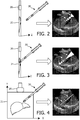
- FIGS. 2-4 shows a sequence of needle 30 being transitioned from out-of-plane to in-plane relative to an ultrasound plane 21.
- FIG. 2 illustrates an initial insertion of needle 30 within abdominal region 12 (not shown) whereby both ultrasound receivers 31 are out-of-plane and an orientation of needle 30 is non-parallel to ultrasound plane 21.
- a needle overlay 48o of a white solid triangular shape based from a proximal end to distal end and a biopsy trajectory overlay 49o of a white dashed triangular shape based from an unfired needle tip to a fired needle tip illustrates both ultrasound receivers 31 are out-of-plane and that a fired needle tip would be out-of-plane.
- FIG. 3 illustrates a further insertion of needle 30 within abdominal region 12 (not shown) whereby the distal ultrasound receiver 31 is in-plane, the proximal ultrasound receiver 31 is out-of-plane, and an orientation of needle 30 is non-parallel to ultrasound plane 21.
- needle overlay 48o and biopsy trajectory overlay 49o illustrates the distal ultrasound receiver 31 is in-plane and the fired needle tip would be out-of-plane opposite needle 30.
- FIG. 4 illustrates a rotation of ultrasound probe 20 relative to the insertion of needle 30 within abdominal region 12 (not shown) whereby both ultrasound receivers 31 are in-plane and therefore needle 30 in-plane to ultrasound plane 21.
- needle overlay 48i is a white line
- biopsy trajectory overlay 49i is a dashed line illustrating the in-plane needle 30.
- needle overlay 48o and biopsy trajectory overlay 49o may be colored red to indicate an out-of-plane needle 30, and needle overlay 48i is and biopsy trajectory overlay 49i may be colored green to indicate an in-plane needle 30.
- trajectory prediction module 47 provides prediction data PD to the appropriate display module(s) of ultrasound guide controller 44 for display of the overlays on the ultrasound image.
- prediction data PD may include a numerical readout of a distance of each ultrasound receiver 31 from the ultrasound plane and an angular orientation of needle 30 relative to the ultrasound plane to facilitate an operator of machine 40 in re-positioning ultrasound probe 20 and/or reinserting needle 30.
- an intervention system of the present invention including, but not limited to, (1) application for various ultrasound-guided target biopsy procedures (e.g., liver biopsy, renal biopsy, etc.), particularly procedures whereby the biopsy needle is not clearly visible during the procedure, and (2) enhanced training for doctors in performing target biopsies.
- various ultrasound-guided target biopsy procedures e.g., liver biopsy, renal biopsy, etc.
- FIGS. 1-4 may be implemented in various combinations of electronic components/circuitry, hardware, executable software and executable firmware, particularly as application modules of a controller as described herein, and provide functions which may be combined in a single element or multiple elements.
- the functions of the various features, elements, components, etc. shown/illustrated/depicted in the FIGS. 1-4 can be provided through the use of dedicated hardware as well as hardware capable of executing software in association with appropriate software.
- processor When provided by a processor, the functions can be provided by a single dedicated processor, by a single shared processor, or by a plurality of individual processors, some of which can be shared and/or multiplexed.
- explicit use of the term "processor” should not be construed to refer exclusively to hardware capable of executing software, and can implicitly include, without limitation, digital signal processor ("DSP") hardware, memory (e.g., read only memory (“ROM”) for storing software, random access memory (“RAM”), non-volatile storage, etc.) and virtually any means and/or machine (including hardware, software, firmware, circuitry, combinations thereof, etc.) which is capable of (and/or configurable) to perform and/or control a process.
- DSP digital signal processor
- any block diagrams presented herein can represent conceptual views of illustrative system components and/or circuitry embodying the principles of the invention.
- any flow charts, flow diagrams and the like can represent various processes which can be substantially represented in computer readable storage media and so executed by a computer, processor or other device with processing capabilities, whether or not such computer or processor is explicitly shown.
- exemplary embodiments of the present invention can take the form of a computer program product or application module accessible from a computer-usable and/or computer-readable storage medium providing program code and/or instructions for use by or in connection with, e.g., a computer or any instruction execution system.
- a computer-usable or computer readable storage medium can be any apparatus that can, e.g., include, store, communicate, propagate or transport the program for use by or in connection with the instruction execution system, apparatus or device.
- Such exemplary medium can be, e.g., an electronic, magnetic, optical, electromagnetic, infrared or semiconductor system (or apparatus or device) or a propagation medium.
- Examples of a computer-readable medium include, e.g., a semiconductor or solid state memory, magnetic tape, a removable computer diskette, a random access memory (RAM), a read-only memory (ROM), flash (drive), a rigid magnetic disk and an optical disk.
- Current examples of optical disks include compact disk - read only memory (CD-ROM), compact disk - read/write (CD-R/W) and DVD.
Landscapes
- Health & Medical Sciences (AREA)
- Life Sciences & Earth Sciences (AREA)
- Engineering & Computer Science (AREA)
- Surgery (AREA)
- Public Health (AREA)
- Animal Behavior & Ethology (AREA)
- Veterinary Medicine (AREA)
- General Health & Medical Sciences (AREA)
- Biomedical Technology (AREA)
- Heart & Thoracic Surgery (AREA)
- Medical Informatics (AREA)
- Molecular Biology (AREA)
- Pathology (AREA)
- Nuclear Medicine, Radiotherapy & Molecular Imaging (AREA)
- Biophysics (AREA)
- Physics & Mathematics (AREA)
- Radiology & Medical Imaging (AREA)
- Gynecology & Obstetrics (AREA)
- Vascular Medicine (AREA)
- Robotics (AREA)
- Ultra Sonic Daignosis Equipment (AREA)
Description
- The present invention generally relates to ultrasound-guided target biopsies (e.g., liver biopsy, renal biopsy, etc.). The present invention specifically relates to a prediction of a needle trajectory during a target biopsy procedure.
- Ultrasound guidance is widely used for target biopsies to increase the accuracy of the procedure and reduce the potential risk of medical accidents. In such procedures, a needle is inserted into the patient aiming at the biopsy target. In the meanwhile, clinicians usually need to estimate the triggered needle trajectory before firing the biopsy gun in order to know if the needle will puncture through the target tissue. The trajectory is approximately an extension of certain centimeters along the needle shaft estimated from the prior knowledge of the needle parameter. Thus, when the needle is clearly visible in the ultrasound image, it may be relatively easy for the physicians to estimate the trajectory. However, in deep organs (e.g., liver and kidney), needles are usually invisible in the ultrasound image due to their specular nature and unfavorable incidence angles, which results in difficulties in estimating the needle trajectory. Moreover, the needle is not always in the ultrasound image plane during the procedure due to the hand motion of the clinician and breathing motion of the patient, which provides more difficulties in estimating the needle trajectory .
WO2012/172458A1 discloses a system for imaging medical device comprising a trilateration module that interprets signals sensed between tracking element and array of transducers to compute times of flight of signals associated with array of transducers.US 2005/159676 A1 discloses a targeted biopsy system which allows planning of tissue to be sampled, targeting of specific areas of tissue in reference to the plan, capturing the tissue sample and recording the source location of the tissue sample, particularly for use in collecting tissue samples from the prostate gland. - To enhance the visualization of interventional tools in ultrasound image, an ultrasound-based tracking technology has been proposed to track a tip of an interventional tool by embedding small ultrasound receivers near the tip of the interventional tool. The position of the interventional tool is then estimated by processing the signal received by these ultrasound receivers, which is then visualized on the ultrasound image. The present invention enhances such ultrasound-based tracking technology by providing a precise prediction of a three-dimensional ("3D") in-plane biopsy trajectory or a 3D out-of-plane biopsy trajectory on the ultrasound image.
- One form of the present invention is a target biopsy system according to claim 4. In operation, the ultrasound probe projects an ultrasound plane intersecting an anatomical region (e.g. an abdominal region, a cranial region, a mammary region, an abdominal region, etc.). The ultrasound receiver(s) sense the ultrasound plane as the target biopsy needle is inserted into the anatomical region. In response to the ultrasound receiver(s) sensing the ultrasound plane, the ultrasound guide controller predicts a biopsy trajectory of the target biopsy needle within the anatomical region relative to ultrasound plane. The prediction indicates the biopsy trajectory is either within the ultrasound plane (i.e., an in-plane biopsy trajectory) or outside of the ultrasound plane (i.e., an out-of-plane biopsy trajectory).
- For purposes of the present invention, the term "ultrasound probe" broadly encompasses any ultrasound probe as known in the art employing one or more ultrasound transducers/transmitters/receivers for projecting an ultrasound plane intersecting the anatomical region. Examples of an ultrasound probe include, but are not limited to, two-dimensional and three-dimensional ultrasound probes with sector, curvilinear or linear geometries.
- For purposes of the present invention, the term "target biopsy needle" broadly encompasses any type of biopsy needle as known in the art employing a stylet or the like to thereby cut a tissue sample when the target biopsy needle is inserted into the anatomical region. Examples of a target biopsy needle include, but is not limited to, guillotine-type biopsy needles with a firing or "gun" mechanism used for core biopsy (e.g., a Bio-Cut® or Bard Magnum® biopsy needle).
- For purposes of the present invention, terms of the art including, but not limited to, "in-plane", "out-of-plane", "receiver", and "biopsy trajectory" are to be interpreted as known in the art of the present invention and exemplary described herein. More particularly, the term "receiver" is inclusive of a receiver and a transceiver as known in the art.
- For purposes of the present invention, the term "ultrasound guide controller" broadly encompasses all structural configurations of an application specific main board or an application specific integrated circuit housed within or linked to a computer or another instruction execution device/system for controlling an application of various inventive principles of the present invention as subsequently described herein. The structural configuration of the ultrasound guide controller may include, but is not limited to, processor(s), computer-usable/computer readable storage medium(s), an operating system, peripheral device controller(s), slot(s) and port(s). Examples of a computer includes, but is not limited to, a server computer, a client computer, a workstation and a tablet.
- A second form of the present invention is the ultrasound guide controller according to claim 1. In operation, the ultrasound probe generates an ultrasound image of an anatomical region responsive to ultrasound data from the ultrasound probe representative of the ultrasound plane intersecting an anatomical region. The receiver tracking module tracks a position of each ultrasound receiver relative to the ultrasound image of the anatomical region responsive to sensing data from the ultrasound receivers representative of a sensing of the ultrasound plane as the target biopsy needle is inserted into the anatomical region. The needle trajectory module predicts the biopsy trajectory of the target biopsy needle relative to the ultrasound plane responsive to the tracked positions of the ultrasound receivers relative to the ultrasound image of the anatomical region.
- For purposes of the present invention, the term "module" broadly encompasses an application component of the ultrasound guide controller consisting of an electronic circuit or an executable program (e.g., executable software and/firmware).
- Another example is a target biopsy method involving (1) the ultrasound probe projecting the ultrasound plane intersecting the anatomical region, (2) the ultrasound receivers sensing the ultrasound plane as a target biopsy needle is inserted into the anatomical region, and (3) the ultrasound guide workstation predicting a biopsy trajectory of the target biopsy needle within the anatomical region relative to the ultrasound plane.
- The foregoing forms and other forms of the present invention as well as various features and advantages of the present invention will become further apparent from the following detailed description of various embodiments of the present invention read in conjunction with the accompanying drawings. The detailed description and drawings are merely illustrative of the present invention rather than limiting, the scope of the present invention being defined by the appended claims.
-
FIG. 1 illustrates an exemplary embodiment of a target biopsy system in accordance with the present invention. -
FIGS. 2-4 illustrate exemplary visualizations of a predicted needle trajectory by the target biopsy system ofFIG. 1 . - To facilitate an understanding of the present invention, exemplary embodiments of the target biopsy system of the present invention will be provided herein for an ultrasound guided target biopsy procedure for a
liver 11 of apatient 10 as shown inFIG. 1 . From the description of the exemplary embodiments of the present invention, those having ordinary skill in the art will appreciate how to make and use the target biopsy system of the present invention for any type of ultrasound-guided target biopsy procedure (e.g., prostate, kidney, breast etc.) involving various types of ultrasound probes and target biopsy needles. - For purposes of the present invention, terms of the art including, but not limited to, "firing mechanism", "co-axial introducer" and "tracked position" are to be interpreted as known in the art of the present invention and exemplary described herein.
- Referring to
FIG. 1 , the ultrasound-guided target biopsy, which does not form part of the present invention, involves anultrasound probe 20 and atarget biopsy needle 30 for extracting tissue fromliver 11 ofpatient 10 as known in the art. -
Ultrasound probe 20 employs one or more ultrasound transducers, transmitters receivers and/or transceivers for projecting an ultrasound plane intersecting an abdominal region 12 (e.g.,ultrasound plane 21 as shown inFIG. 2 ). Examples ofultrasound probe 20 include, but are not limited to, two-dimensional and three-dimensional ultrasound probes with sector, curvilinear or linear geometries. -
Target biopsy needle 30 employs a stylet or the like to thereby cut a tissue sample ofliver 11 whenneedle 30 is inserted intoabdominal region 12. Examples oftarget biopsy needle 30 include, but is not limited to, guillotine-type biopsy needles with an automatic/semi-automatic firing or "gun" mechanism used for core biopsy (e.g., a Bio-Cut® or Bard Magnum® biopsy needle). When included, a fire mechanism is operated to project target biopsy needle along a biopsy trajectory of target biopsy needle withinabdominal region 12. - Two or more ultrasound receivers 31 (i.e., a receiver or a transceiver) for sensing the ultrasound plane are attached as
target biopsy needle 30 is being inserted withinabdominal region 12 ofpatient 10. As known in the art, a degree of sensing the ultrasound plane is a function of a distance between an ultrasound receiver 31 and the ultrasound plane. - In practice, ultrasound receivers 31 are spatially arranged on
biopsy needle 30 suitable for facilitating a distinctive sensing of the ultrasound plane by each ultrasound receiver 31. In one embodiment, as shown inFIG. 1 ,distal ultrasound receiver 31d is attached to/embedded withintarget biopsy needle 30 adjacent a tip oftarget biopsy needle 30 and aproximal ultrasound receiver 31p is attached to/embedded withintarget biopsy needle 30 is a middle of shaft oftarget biopsy needle 30. In an alternative embodiment,target biopsy needle 30 includes a coaxial introducer through whichtarget biopsy needle 30 intoabdominal region 12 with receivers 31 being attached to/embedded within the coaxial introducer. - The ultrasound-guided target biopsy procedure involves an
ultrasound guide machine 40 employing amonitor 41, aninterface platform 42, aworkstation 43 and aultrasound guide controller 44 installed withinworkstation 43. While not shown, in practice,ultrasound probe 20 and ultrasound receivers 31 are connected/coupled toworkstation 43 in any manner as known in the art. -
Ultrasound guide controller 44 includes and/or is accessible by an operating system (not shown) as known in the art for controlling various graphical user interfaces, data and images onmonitor 41 as directed by a workstation operator (e.g., a doctor, technician, etc.) via a keyboard, buttons, dials, joysticks, etc. ofinterface platform 42, and for storing/reading data as programmed and/or directed by the workstation operator ofinterface platform 42. -
Ultrasound guide controller 44 further executes application modules including anultrasound imaging module 45, areceiver tracking module 46, and atrajectory prediction module 47 for implementing an ultrasound guided target biopsy procedure ofliver 11. - Specifically,
ultrasound imaging module 45 is structurally configured to receive ultrasound data UD fromultrasound probe 20 representative of the ultrasound plane intersectingabdominal region 12 ofpatient 11, and to execute a known process for generating a planar ultrasound image ofabdominal region 12 for display bymonitor 41 as shown. -
Receiver tracking module 46 is structurally configured to sense data SD from ultrasound receivers 31 representative of a sensing of the ultrasound plane as thetarget biopsy needle 30 is inserted intoabdominal region 12 ofpatient 11, and to execute a known process for tracking a position of each ultrasound receiver 31 relative to the ultrasound plane intersectingabdominal region 12. For each ultrasound receiver 31, the tracked position indicates whether the particular ultrasound receiver 31 is within the ultrasound plane (i.e., in-plane) or outside of the ultrasound plane (i.e., out-of-plane). More particularly, the sensing of the ultrasound plane of the particular ultrasound receiver 31 will indicate a three-dimensional ("3D") position of each ultrasound receiver 31 in terms of height, width and depth whereby in-plane has zero (0) depth and out-of-plane has a non-zero depth. -
Trajectory prediction module 47 is structurally configured to receive needle data ND, pre-operatively or intra-operatively, representative of a dimension/configuration profile oftarget biopsy needle 30 whereby parameters ofneedle 30 are known for determining an orientation ofneedle 30 relative to the ultrasound plane intersectingabdominal region 12 including, but not limited to, (1) a length ofneedle 30 prior to and subsequent to a firing ofneedle 30 and (2) an attachment point of each ultrasound receiver 31. -
Trajectory prediction module 47 is further structurally configured to receive image data ID fromultrasound imaging module 45 representative of the planar ultrasound image ofabdominal region 12 being displayed, and tracking data TD fromreceiver tracking module 46 representative of the tracked positions of ultrasound receivers 31 relative to the ultrasound plane intersectingabdominal region 12. In response thereto,trajectory prediction module 47 is further structurally configured to receive to predict a biopsy trajectory oftarget biopsy needle 30 relative to the ultrasound plane by executing a process of the present invention including: - (1) determining an orientation of a virtual version of an
unfired needle 30 relative to the planar ultrasound image derived from a length of a virtual positioning of a segment ofneedle 30 between ultrasound receivers 31 relative to the planar ultrasound image as a function of the tracked positions of ultrasound receivers 31 ("orientation determination"); and - (2) determining a tip extension of a virtual version of a fired
needle 30 previously oriented relative to the planar ultrasound image derived from a length of a virtual positioning of a fired stylet of needle 30 ("firing determination"). - The orientation determination facilitates a generation by
trajectory prediction module 47 of a needle overlay on the planar ultrasound image, and the firing determination facilitates a generation bytrajectory prediction module 47 of a biopsy trajectory overlay on the planar ultrasound image. For example, as shown inFIG. 1 , monitor 41 is displaying an in-plane needle overlay 48i and an in-plane biopsy trajectory overlay 49i when both ultrasound receivers 31 are in-plane of the ultrasound plane intersectingabdominal region 12. - In practice, the overlays may have any shape and/or any color indicative of an in-plane or out-of-plane sensing of
needle 30 and the biopsy trajectory. For example,FIGS. 2-4 shows a sequence ofneedle 30 being transitioned from out-of-plane to in-plane relative to anultrasound plane 21. - Specifically,
FIG. 2 illustrates an initial insertion ofneedle 30 within abdominal region 12 (not shown) whereby both ultrasound receivers 31 are out-of-plane and an orientation ofneedle 30 is non-parallel toultrasound plane 21. For this initial insertion, a needle overlay 48o of a white solid triangular shape based from a proximal end to distal end and a biopsy trajectory overlay 49o of a white dashed triangular shape based from an unfired needle tip to a fired needle tip illustrates both ultrasound receivers 31 are out-of-plane and that a fired needle tip would be out-of-plane. -
FIG. 3 illustrates a further insertion ofneedle 30 within abdominal region 12 (not shown) whereby the distal ultrasound receiver 31 is in-plane, the proximal ultrasound receiver 31 is out-of-plane, and an orientation ofneedle 30 is non-parallel toultrasound plane 21. For this further insertion, needle overlay 48o and biopsy trajectory overlay 49o illustrates the distal ultrasound receiver 31 is in-plane and the fired needle tip would be out-of-plane oppositeneedle 30. -
FIG. 4 illustrates a rotation ofultrasound probe 20 relative to the insertion ofneedle 30 within abdominal region 12 (not shown) whereby both ultrasound receivers 31 are in-plane and therefore needle 30 in-plane toultrasound plane 21. For this probe rotation, needle overlay 48i is a white line and biopsy trajectory overlay 49i is a dashed line illustrating the in-plane needle 30. - For the example of
FIGS. 2-4 , needle overlay 48o and biopsy trajectory overlay 49o may be colored red to indicate an out-of-plane needle 30, and needle overlay 48i is and biopsy trajectory overlay 49i may be colored green to indicate an in-plane needle 30. - Referring back to
FIG. 1 ,trajectory prediction module 47 provides prediction data PD to the appropriate display module(s) ofultrasound guide controller 44 for display of the overlays on the ultrasound image. Additionally, prediction data PD may include a numerical readout of a distance of each ultrasound receiver 31 from the ultrasound plane and an angular orientation ofneedle 30 relative to the ultrasound plane to facilitate an operator ofmachine 40 inre-positioning ultrasound probe 20 and/or reinsertingneedle 30. - Referring to
FIGS. 1-4 , from the description of the exemplary embodiments of the present invention, those having ordinary skill in the art will appreciate numerous benefits of an intervention system of the present invention including, but not limited to, (1) application for various ultrasound-guided target biopsy procedures (e.g., liver biopsy, renal biopsy, etc.), particularly procedures whereby the biopsy needle is not clearly visible during the procedure, and (2) enhanced training for doctors in performing target biopsies. - Furthermore, as one having ordinary skill in the art will appreciate in view of the teachings provided herein, features, elements, components, etc. described in the present disclosure/specification and/or depicted in the
FIGS. 1-4 may be implemented in various combinations of electronic components/circuitry, hardware, executable software and executable firmware, particularly as application modules of a controller as described herein, and provide functions which may be combined in a single element or multiple elements. For example, the functions of the various features, elements, components, etc. shown/illustrated/depicted in theFIGS. 1-4 can be provided through the use of dedicated hardware as well as hardware capable of executing software in association with appropriate software. When provided by a processor, the functions can be provided by a single dedicated processor, by a single shared processor, or by a plurality of individual processors, some of which can be shared and/or multiplexed. Moreover, explicit use of the term "processor" should not be construed to refer exclusively to hardware capable of executing software, and can implicitly include, without limitation, digital signal processor ("DSP") hardware, memory (e.g., read only memory ("ROM") for storing software, random access memory ("RAM"), non-volatile storage, etc.) and virtually any means and/or machine (including hardware, software, firmware, circuitry, combinations thereof, etc.) which is capable of (and/or configurable) to perform and/or control a process. - It will be appreciated by one having ordinary skill in the art in view of the teachings provided herein that any block diagrams presented herein can represent conceptual views of illustrative system components and/or circuitry embodying the principles of the invention. Similarly, one having ordinary skill in the art should appreciate in view of the teachings provided herein that any flow charts, flow diagrams and the like can represent various processes which can be substantially represented in computer readable storage media and so executed by a computer, processor or other device with processing capabilities, whether or not such computer or processor is explicitly shown.
- Furthermore, exemplary embodiments of the present invention can take the form of a computer program product or application module accessible from a computer-usable and/or computer-readable storage medium providing program code and/or instructions for use by or in connection with, e.g., a computer or any instruction execution system. In accordance with the present disclosure, a computer-usable or computer readable storage medium can be any apparatus that can, e.g., include, store, communicate, propagate or transport the program for use by or in connection with the instruction execution system, apparatus or device. Such exemplary medium can be, e.g., an electronic, magnetic, optical, electromagnetic, infrared or semiconductor system (or apparatus or device) or a propagation medium. Examples of a computer-readable medium include, e.g., a semiconductor or solid state memory, magnetic tape, a removable computer diskette, a random access memory (RAM), a read-only memory (ROM), flash (drive), a rigid magnetic disk and an optical disk. Current examples of optical disks include compact disk - read only memory (CD-ROM), compact disk - read/write (CD-R/W) and DVD. Further, it should be understood that any new computer-readable medium which may hereafter be developed should also be considered as computer-readable medium as may be used or referred to in accordance with exemplary embodiments of the present invention and disclosure.
- Having described preferred and exemplary embodiments of novel and inventive system for predicting a needle trajectory for target biopsy, (which embodiments are intended to be illustrative and not limiting), it is noted that modifications and variations can be made by persons having ordinary skill in the art in light of the teachings provided herein, including the
FIGS 1-4 . It is therefore to be understood that changes can be made in/to the preferred and exemplary embodiments of the present disclosure which are within the scope of the embodiments disclosed herein. - Moreover, it is contemplated that corresponding and/or related systems incorporating and/or implementing the device or such as may be used/implemented in a device in accordance with the present disclosure are also contemplated and considered to be within the scope of the present invention.
Claims (13)
- A ultrasound guide controller (44) configured to control a target biopsy system that includes i) an ultrasound probe (20) operable to project an ultrasound plane intersecting an anatomical region and ii) a target biopsy needle (30) having at least two ultrasound receivers (31) arranged thereon in a known arrangement relative to the target biopsy needle (30) and in which each ultrasound receiver (31) is operable to sense the ultrasound plane as the target biopsy needle (30) is inserted into the anatomical region, the ultrasound guide controller (44) comprising:an ultrasound imaging module (45), configured based on ultrasound data received from the ultrasound probe (20), to generate a planar ultrasound image of an anatomical region responsive to ultrasound data representative of an ultrasound plane intersecting the anatomical region;a receiver tracking module (46), configured based on sense data received from the at least two ultrasound receivers (31), to track a position of each ultrasound receiver (31) relative to the ultrasound plane responsive to sensing data representative of a sensing of the ultrasound plane as the target biopsy needle (30) is inserted into the anatomical region; anda trajectory prediction module (47) operable in communication with the ultrasound imaging module (45) and the receiver tracking module (46) to predict a biopsy trajectory of the target biopsy needle (30) relative to the ultrasound plane responsive to the tracked positions of the at least two ultrasound receivers (31) relative to the planar ultrasound image of the anatomical region; characterized by said prediction being based ona) a known length of the target biopsy needle (30) prior to firing, b) a known length of the target biopsy needle (30) subsequent to firing, and c) a known attachment point of each ultrasound receiver (31), said prediction including:determining an orientation of a virtual version of an unfired needle (30) relative to the planar ultrasound image derived from a length of a virtual positioning of a segment of the target biopsy needle (30) between the ultrasound receivers (31) relative to the planar ultrasound image as a function of the tracked positions of the ultrasound receivers (31); anddetermining a tip extension of a virtual version of a fired needle (30) previously oriented relative to the planar ultrasound image derived from a length of a virtual positioning of a fired stylet of the target biopsy needle (30).
- The ultrasound guide controller (44) of claim 1, wherein the trajectory prediction module (47) is configured to predict the biopsy trajectory as an in-plane biopsy trajectory responsive to the tracked positions of the at least two ultrasound receivers (31) indicating the at least two ultrasound receivers (31) being within the ultrasound plane.
- The ultrasound guide controller (44) of claim 1, wherein the trajectory prediction module (47) is configured to predict the biopsy trajectory as an out-of-plane biopsy trajectory responsive to the tracked positions of the at least two ultrasound receivers (31) indicating at least one of the at least two ultrasound receivers (31) being outside the ultrasound plane.
- A target biopsy system, comprising the ultrasound guide controller (44) of claim 1 and further comprising:the ultrasound probe (20); andthe target biopsy needle (30) having the at least two ultrasound receivers (31) arranged thereon.
- The target biopsy system of claim 4, wherein the target biopsy needle (30) includes a firing mechanism operable to project the target biopsy needle (30) along the predicted biopsy trajectory of the target biopsy needle (30) within the anatomical region.
- The target biopsy system of claim 4, wherein the target biopsy needle (30) includes a coaxial introducer operable to introduce the target biopsy needle (30) into the anatomical region.
- The target biopsy system of clam 4,
wherein a distal ultrasound receiver (31) of the at least two ultrasound receivers (31) is adjacent a tip of the target biopsy needle (30); and
wherein each additional ultrasound receiver (31) of the at least two ultrasound receiver (31) are spatially arranged on the target biopsy needle (30). - The target biopsy system of claim 4, wherein the ultrasound guide controller (44) is configured to predict the biopsy trajectory as an in-plane biopsy trajectory responsive to the sensing of the ultrasound plane indicating the at least two ultrasound receivers (31) being within the ultrasound plane.
- The target biopsy system of claim 8, wherein the ultrasound guide controller (44) is configured to predict the biopsy trajectory as an out-of-plane biopsy trajectory responsive to the sensing of the ultrasound plane indicating at least one of the at least two ultrasound receivers (31) being outside the ultrasound plane.
- The target biopsy system of claim 4, further comprising:
a monitor (41) operable in communication with the ultrasound guide controller (44) to display the planar ultrasound image; and
wherein the ultrasound guide controller (44) is operable to control a display of a biopsy trajectory overlay on a planar ultrasound image of the anatomical region displayed by the monitor (41), the biopsy trajectory overlay being derived from a prediction of the biopsy trajectory of the target biopsy needle (30) within the anatomical region relative to the ultrasound plane. - The target biopsy system of claim 10, wherein the ultrasound guide controller (44) is configured to control the display of the biopsy trajectory overlay as an in-plane biopsy trajectory responsive to the at least two ultrasound receivers (31) being within the ultrasound plane.
- The target biopsy system of claim 10, wherein the ultrasound guide controller (44) is configured to control the display of the biopsy trajectory overlay as an out-of-plane biopsy trajectory responsive to at least one of the at least two ultrasound receivers (31) being outside the ultrasound plane.
- The target biopsy system of claim 10, further comprising:
an interface platform (42) operable in communication with the ultrasound guide controller (44) to control the display of the planar ultrasound image by the monitor (41).
Applications Claiming Priority (2)
| Application Number | Priority Date | Filing Date | Title |
|---|---|---|---|
| US201462096569P | 2014-12-24 | 2014-12-24 | |
| PCT/IB2015/059494 WO2016103094A1 (en) | 2014-12-24 | 2015-12-10 | Needle trajectory prediction for target biopsy |
Publications (2)
| Publication Number | Publication Date |
|---|---|
| EP3236859A1 EP3236859A1 (en) | 2017-11-01 |
| EP3236859B1 true EP3236859B1 (en) | 2021-03-31 |
Family
ID=55066697
Family Applications (1)
| Application Number | Title | Priority Date | Filing Date |
|---|---|---|---|
| EP15817563.8A Active EP3236859B1 (en) | 2014-12-24 | 2015-12-10 | Needle trajectory prediction for target biopsy |
Country Status (5)
| Country | Link |
|---|---|
| US (1) | US20180000446A1 (en) |
| EP (1) | EP3236859B1 (en) |
| JP (1) | JP2018500997A (en) |
| CN (1) | CN107106126B (en) |
| WO (1) | WO2016103094A1 (en) |
Families Citing this family (25)
| Publication number | Priority date | Publication date | Assignee | Title |
|---|---|---|---|---|
| WO2007095330A2 (en) | 2006-02-15 | 2007-08-23 | Hologic Inc | Breast biopsy and needle localization using tomosynthesis systems |
| US10595954B2 (en) | 2009-10-08 | 2020-03-24 | Hologic, Inc. | Needle breast biopsy system and method for use |
| US9075903B2 (en) | 2010-11-26 | 2015-07-07 | Hologic, Inc. | User interface for medical image review workstation |
| CN110353709A (en) | 2011-03-08 | 2019-10-22 | 霍洛吉克公司 | The system and method for dual intensity and/or radiography enhancing breast imaging |
| JP2014534042A (en) | 2011-11-27 | 2014-12-18 | ホロジック, インコーポレイテッドHologic, Inc. | System and method for generating 2D images using mammography and / or tomosynthesis image data |
| CN104135935A (en) | 2012-02-13 | 2014-11-05 | 霍罗吉克公司 | System and method for navigating a tomosynthesis stack using synthesized image data |
| WO2014151646A1 (en) | 2013-03-15 | 2014-09-25 | Hologic Inc. | Tomosynthesis-guided biopsy in prone |
| AU2014339982B2 (en) | 2013-10-24 | 2019-04-18 | Hologic, Inc. | System and method for navigating x-ray guided breast biopsy |
| CA2937379C (en) | 2014-02-28 | 2022-08-09 | Hologic, Inc. | System and method for generating and displaying tomosynthesis image slabs |
| EP3582692A1 (en) * | 2017-02-14 | 2019-12-25 | Koninklijke Philips N.V. | Path tracking in ultrasound system for device tracking |
| US11445993B2 (en) | 2017-03-30 | 2022-09-20 | Hologic, Inc. | System and method for targeted object enhancement to generate synthetic breast tissue images |
| WO2018183548A1 (en) | 2017-03-30 | 2018-10-04 | Hologic, Inc. | System and method for hierarchical multi-level feature image synthesis and representation |
| EP3600051B1 (en) | 2017-03-30 | 2024-05-01 | Hologic, Inc. | Method for synthesizing low-dimensional image data from high-dimensional image data using an object grid enhancement |
| US11403483B2 (en) | 2017-06-20 | 2022-08-02 | Hologic, Inc. | Dynamic self-learning medical image method and system |
| AU2018333123A1 (en) * | 2017-09-15 | 2020-04-09 | Elesta S.p.A. | Device and method for needle sonographic guidance in minimally invasive procedures |
| US20210000553A1 (en) * | 2018-05-04 | 2021-01-07 | Hologic, Inc. | Introducer and localization wire visualization |
| EP3787520A1 (en) * | 2018-05-04 | 2021-03-10 | Hologic, Inc. | Biopsy needle visualization |
| WO2020002620A1 (en) * | 2018-06-29 | 2020-01-02 | Koninklijke Philips N.V. | Biopsy prediction and guidance with ultrasound imaging and associated devices, systems, and methods |
| US11642100B2 (en) * | 2018-09-20 | 2023-05-09 | Mayo Foundation For Medical Education And Research | Systems and methods for localizing a medical device using symmetric Doppler frequency shifts measured with ultrasound imaging |
| CN113015489A (en) * | 2018-10-25 | 2021-06-22 | 皇家飞利浦有限公司 | System and method for estimating a position of a tip of an interventional device in acoustic imaging |
| US11129588B2 (en) * | 2019-06-19 | 2021-09-28 | Paul Adams | Ultrasound probe with an integrated needle assembly and a computer program product, a method and a system for providing a path for inserting a needle of the ultrasound probe |
| US11883206B2 (en) | 2019-07-29 | 2024-01-30 | Hologic, Inc. | Personalized breast imaging system |
| KR20220069946A (en) | 2019-09-27 | 2022-05-27 | 홀로직, 인크. | AI system to predict read time and read complexity for reviewing 2D/3D breast images |
| US11481038B2 (en) | 2020-03-27 | 2022-10-25 | Hologic, Inc. | Gesture recognition in controlling medical hardware or software |
| JP2023077827A (en) * | 2021-11-25 | 2023-06-06 | 富士フイルム株式会社 | Ultrasonic diagnostic device and control method of ultrasonic diagnostic device |
Family Cites Families (14)
| Publication number | Priority date | Publication date | Assignee | Title |
|---|---|---|---|---|
| KR19990029038A (en) * | 1995-07-16 | 1999-04-15 | 요아브 빨띠에리 | Free aiming of needle ceramic |
| JPH1176241A (en) * | 1997-09-10 | 1999-03-23 | Nippon Vinyl Kogyo Kk | Ultrasonic diagnostic apparatus |
| JP4443672B2 (en) * | 1998-10-14 | 2010-03-31 | 株式会社東芝 | Ultrasonic diagnostic equipment |
| US7068867B2 (en) * | 2003-01-02 | 2006-06-27 | Glucon Medical Ltd | Ultrasonic position indicator |
| US20050159676A1 (en) * | 2003-08-13 | 2005-07-21 | Taylor James D. | Targeted biopsy delivery system |
| HRP20030990A2 (en) * | 2003-11-27 | 2006-02-28 | Branko Breyer Ivo Čikeš | System for guidance and control of minimum invasive delivery of therapy with medical agents |
| WO2006116163A2 (en) * | 2005-04-21 | 2006-11-02 | Biotelligent Inc. | Ultrasound guided tissue measurement system |
| CN102105190B (en) * | 2008-05-28 | 2014-12-10 | 泰克尼恩研究和发展基金有限公司 | Ultrasound guided robot for flexible needle steering |
| WO2010125505A1 (en) * | 2009-04-28 | 2010-11-04 | Koninklijke Philips Electronics N.V. | Biopsy guide system with an ultrasound transducer and method of using same |
| WO2011114259A1 (en) * | 2010-03-19 | 2011-09-22 | Koninklijke Philips Electronics N.V. | Automatic positioning of imaging plane in ultrasonic imaging |
| US9282946B2 (en) * | 2010-05-03 | 2016-03-15 | Koninklijke Philips N.V. | Ultrasonic tracking of ultrasound transducer(s) aboard an interventional tool |
| CN103747729B (en) * | 2011-06-13 | 2016-07-13 | 皇家飞利浦有限公司 | Utilize the three dimensional needle location that two-dimensional imaging is popped one's head in |
| BR112014017369B1 (en) * | 2012-01-18 | 2022-03-03 | Koninklijke Philips N.V. | Ultrasonic imaging system that visually guides the insertion of an invasive device such as a needle |
| GB201307551D0 (en) * | 2013-04-26 | 2013-06-12 | Ucl Business Plc | A method and apparatus for determining the location of a medical instrument with respect to ultrasound imaging and a medical instrument |
-
2015
- 2015-12-10 CN CN201580070658.2A patent/CN107106126B/en active Active
- 2015-12-10 JP JP2017533581A patent/JP2018500997A/en active Pending
- 2015-12-10 EP EP15817563.8A patent/EP3236859B1/en active Active
- 2015-12-10 WO PCT/IB2015/059494 patent/WO2016103094A1/en active Application Filing
- 2015-12-10 US US15/537,497 patent/US20180000446A1/en not_active Abandoned
Non-Patent Citations (1)
| Title |
|---|
| None * |
Also Published As
| Publication number | Publication date |
|---|---|
| CN107106126A (en) | 2017-08-29 |
| WO2016103094A1 (en) | 2016-06-30 |
| US20180000446A1 (en) | 2018-01-04 |
| JP2018500997A (en) | 2018-01-18 |
| EP3236859A1 (en) | 2017-11-01 |
| CN107106126B (en) | 2021-05-28 |
Similar Documents
| Publication | Publication Date | Title |
|---|---|---|
| EP3236859B1 (en) | Needle trajectory prediction for target biopsy | |
| US11103200B2 (en) | Medical device approaches | |
| CN107666876B (en) | Intraoperative accuracy feedback system and device for image-guided biopsy | |
| US11596475B2 (en) | Systems and methods for ultrasound image-guided ablation antenna placement | |
| US20200237403A1 (en) | Systems And Methods For Tracking Medical Devices | |
| US20160317225A1 (en) | Microwave ablation planning and procedure systems using a three-dimensional model of a patient | |
| CN107106240B (en) | Show method and system of the linear instrument relative to position and orientation after the navigation of 3D medical image | |
| US11259774B2 (en) | Registration of optical shape sensing tool | |
| US9558405B2 (en) | Imaging based instrument event tracking | |
| US9892557B2 (en) | Integrated system for focused treatment and methods thereof | |
| EP3366252A1 (en) | Ultrasound doppler and elastography for ablation prediction and monitoring | |
| US20230372024A1 (en) | Synthetic position in space of an endoluminal instrument | |
| EP3545852B1 (en) | Electromagnetic navigation bronchoscopy using ultrasound |
Legal Events
| Date | Code | Title | Description |
|---|---|---|---|
| STAA | Information on the status of an ep patent application or granted ep patent |
Free format text: STATUS: THE INTERNATIONAL PUBLICATION HAS BEEN MADE |
|
| PUAI | Public reference made under article 153(3) epc to a published international application that has entered the european phase |
Free format text: ORIGINAL CODE: 0009012 |
|
| STAA | Information on the status of an ep patent application or granted ep patent |
Free format text: STATUS: REQUEST FOR EXAMINATION WAS MADE |
|
| 17P | Request for examination filed |
Effective date: 20170724 |
|
| AK | Designated contracting states |
Kind code of ref document: A1 Designated state(s): AL AT BE BG CH CY CZ DE DK EE ES FI FR GB GR HR HU IE IS IT LI LT LU LV MC MK MT NL NO PL PT RO RS SE SI SK SM TR |
|
| AX | Request for extension of the european patent |
Extension state: BA ME |
|
| DAV | Request for validation of the european patent (deleted) | ||
| DAX | Request for extension of the european patent (deleted) | ||
| STAA | Information on the status of an ep patent application or granted ep patent |
Free format text: STATUS: EXAMINATION IS IN PROGRESS |
|
| 17Q | First examination report despatched |
Effective date: 20190212 |
|
| RAP1 | Party data changed (applicant data changed or rights of an application transferred) |
Owner name: KONINKLIJKE PHILIPS N.V. |
|
| GRAP | Despatch of communication of intention to grant a patent |
Free format text: ORIGINAL CODE: EPIDOSNIGR1 |
|
| STAA | Information on the status of an ep patent application or granted ep patent |
Free format text: STATUS: GRANT OF PATENT IS INTENDED |
|
| INTG | Intention to grant announced |
Effective date: 20201016 |
|
| GRAS | Grant fee paid |
Free format text: ORIGINAL CODE: EPIDOSNIGR3 |
|
| GRAA | (expected) grant |
Free format text: ORIGINAL CODE: 0009210 |
|
| STAA | Information on the status of an ep patent application or granted ep patent |
Free format text: STATUS: THE PATENT HAS BEEN GRANTED |
|
| AK | Designated contracting states |
Kind code of ref document: B1 Designated state(s): AL AT BE BG CH CY CZ DE DK EE ES FI FR GB GR HR HU IE IS IT LI LT LU LV MC MK MT NL NO PL PT RO RS SE SI SK SM TR |
|
| REG | Reference to a national code |
Ref country code: GB Ref legal event code: FG4D Ref country code: CH Ref legal event code: EP |
|
| REG | Reference to a national code |
Ref country code: DE Ref legal event code: R096 Ref document number: 602015067533 Country of ref document: DE Ref country code: AT Ref legal event code: REF Ref document number: 1376034 Country of ref document: AT Kind code of ref document: T Effective date: 20210415 |
|
| REG | Reference to a national code |
Ref country code: IE Ref legal event code: FG4D |
|
| REG | Reference to a national code |
Ref country code: LT Ref legal event code: MG9D |
|
| PG25 | Lapsed in a contracting state [announced via postgrant information from national office to epo] |
Ref country code: NO Free format text: LAPSE BECAUSE OF FAILURE TO SUBMIT A TRANSLATION OF THE DESCRIPTION OR TO PAY THE FEE WITHIN THE PRESCRIBED TIME-LIMIT Effective date: 20210630 Ref country code: FI Free format text: LAPSE BECAUSE OF FAILURE TO SUBMIT A TRANSLATION OF THE DESCRIPTION OR TO PAY THE FEE WITHIN THE PRESCRIBED TIME-LIMIT Effective date: 20210331 Ref country code: HR Free format text: LAPSE BECAUSE OF FAILURE TO SUBMIT A TRANSLATION OF THE DESCRIPTION OR TO PAY THE FEE WITHIN THE PRESCRIBED TIME-LIMIT Effective date: 20210331 Ref country code: BG Free format text: LAPSE BECAUSE OF FAILURE TO SUBMIT A TRANSLATION OF THE DESCRIPTION OR TO PAY THE FEE WITHIN THE PRESCRIBED TIME-LIMIT Effective date: 20210630 |
|
| PG25 | Lapsed in a contracting state [announced via postgrant information from national office to epo] |
Ref country code: SE Free format text: LAPSE BECAUSE OF FAILURE TO SUBMIT A TRANSLATION OF THE DESCRIPTION OR TO PAY THE FEE WITHIN THE PRESCRIBED TIME-LIMIT Effective date: 20210331 Ref country code: LV Free format text: LAPSE BECAUSE OF FAILURE TO SUBMIT A TRANSLATION OF THE DESCRIPTION OR TO PAY THE FEE WITHIN THE PRESCRIBED TIME-LIMIT Effective date: 20210331 Ref country code: RS Free format text: LAPSE BECAUSE OF FAILURE TO SUBMIT A TRANSLATION OF THE DESCRIPTION OR TO PAY THE FEE WITHIN THE PRESCRIBED TIME-LIMIT Effective date: 20210331 |
|
| REG | Reference to a national code |
Ref country code: NL Ref legal event code: MP Effective date: 20210331 |
|
| REG | Reference to a national code |
Ref country code: AT Ref legal event code: MK05 Ref document number: 1376034 Country of ref document: AT Kind code of ref document: T Effective date: 20210331 |
|
| PG25 | Lapsed in a contracting state [announced via postgrant information from national office to epo] |
Ref country code: SM Free format text: LAPSE BECAUSE OF FAILURE TO SUBMIT A TRANSLATION OF THE DESCRIPTION OR TO PAY THE FEE WITHIN THE PRESCRIBED TIME-LIMIT Effective date: 20210331 Ref country code: AT Free format text: LAPSE BECAUSE OF FAILURE TO SUBMIT A TRANSLATION OF THE DESCRIPTION OR TO PAY THE FEE WITHIN THE PRESCRIBED TIME-LIMIT Effective date: 20210331 Ref country code: CZ Free format text: LAPSE BECAUSE OF FAILURE TO SUBMIT A TRANSLATION OF THE DESCRIPTION OR TO PAY THE FEE WITHIN THE PRESCRIBED TIME-LIMIT Effective date: 20210331 Ref country code: EE Free format text: LAPSE BECAUSE OF FAILURE TO SUBMIT A TRANSLATION OF THE DESCRIPTION OR TO PAY THE FEE WITHIN THE PRESCRIBED TIME-LIMIT Effective date: 20210331 Ref country code: NL Free format text: LAPSE BECAUSE OF FAILURE TO SUBMIT A TRANSLATION OF THE DESCRIPTION OR TO PAY THE FEE WITHIN THE PRESCRIBED TIME-LIMIT Effective date: 20210331 Ref country code: LT Free format text: LAPSE BECAUSE OF FAILURE TO SUBMIT A TRANSLATION OF THE DESCRIPTION OR TO PAY THE FEE WITHIN THE PRESCRIBED TIME-LIMIT Effective date: 20210331 |
|
| PG25 | Lapsed in a contracting state [announced via postgrant information from national office to epo] |
Ref country code: RO Free format text: LAPSE BECAUSE OF FAILURE TO SUBMIT A TRANSLATION OF THE DESCRIPTION OR TO PAY THE FEE WITHIN THE PRESCRIBED TIME-LIMIT Effective date: 20210331 Ref country code: SK Free format text: LAPSE BECAUSE OF FAILURE TO SUBMIT A TRANSLATION OF THE DESCRIPTION OR TO PAY THE FEE WITHIN THE PRESCRIBED TIME-LIMIT Effective date: 20210331 Ref country code: PT Free format text: LAPSE BECAUSE OF FAILURE TO SUBMIT A TRANSLATION OF THE DESCRIPTION OR TO PAY THE FEE WITHIN THE PRESCRIBED TIME-LIMIT Effective date: 20210802 Ref country code: PL Free format text: LAPSE BECAUSE OF FAILURE TO SUBMIT A TRANSLATION OF THE DESCRIPTION OR TO PAY THE FEE WITHIN THE PRESCRIBED TIME-LIMIT Effective date: 20210331 Ref country code: IS Free format text: LAPSE BECAUSE OF FAILURE TO SUBMIT A TRANSLATION OF THE DESCRIPTION OR TO PAY THE FEE WITHIN THE PRESCRIBED TIME-LIMIT Effective date: 20210731 |
|
| REG | Reference to a national code |
Ref country code: DE Ref legal event code: R097 Ref document number: 602015067533 Country of ref document: DE |
|
| PG25 | Lapsed in a contracting state [announced via postgrant information from national office to epo] |
Ref country code: ES Free format text: LAPSE BECAUSE OF FAILURE TO SUBMIT A TRANSLATION OF THE DESCRIPTION OR TO PAY THE FEE WITHIN THE PRESCRIBED TIME-LIMIT Effective date: 20210331 Ref country code: AL Free format text: LAPSE BECAUSE OF FAILURE TO SUBMIT A TRANSLATION OF THE DESCRIPTION OR TO PAY THE FEE WITHIN THE PRESCRIBED TIME-LIMIT Effective date: 20210331 Ref country code: DK Free format text: LAPSE BECAUSE OF FAILURE TO SUBMIT A TRANSLATION OF THE DESCRIPTION OR TO PAY THE FEE WITHIN THE PRESCRIBED TIME-LIMIT Effective date: 20210331 |
|
| PLBE | No opposition filed within time limit |
Free format text: ORIGINAL CODE: 0009261 |
|
| STAA | Information on the status of an ep patent application or granted ep patent |
Free format text: STATUS: NO OPPOSITION FILED WITHIN TIME LIMIT |
|
| 26N | No opposition filed |
Effective date: 20220104 |
|
| PG25 | Lapsed in a contracting state [announced via postgrant information from national office to epo] |
Ref country code: IS Free format text: LAPSE BECAUSE OF FAILURE TO SUBMIT A TRANSLATION OF THE DESCRIPTION OR TO PAY THE FEE WITHIN THE PRESCRIBED TIME-LIMIT Effective date: 20210731 |
|
| PG25 | Lapsed in a contracting state [announced via postgrant information from national office to epo] |
Ref country code: MC Free format text: LAPSE BECAUSE OF FAILURE TO SUBMIT A TRANSLATION OF THE DESCRIPTION OR TO PAY THE FEE WITHIN THE PRESCRIBED TIME-LIMIT Effective date: 20210331 Ref country code: IT Free format text: LAPSE BECAUSE OF FAILURE TO SUBMIT A TRANSLATION OF THE DESCRIPTION OR TO PAY THE FEE WITHIN THE PRESCRIBED TIME-LIMIT Effective date: 20210331 |
|
| REG | Reference to a national code |
Ref country code: CH Ref legal event code: PL |
|
| REG | Reference to a national code |
Ref country code: BE Ref legal event code: MM Effective date: 20211231 |
|
| PG25 | Lapsed in a contracting state [announced via postgrant information from national office to epo] |
Ref country code: LU Free format text: LAPSE BECAUSE OF NON-PAYMENT OF DUE FEES Effective date: 20211210 Ref country code: IE Free format text: LAPSE BECAUSE OF NON-PAYMENT OF DUE FEES Effective date: 20211210 |
|
| PG25 | Lapsed in a contracting state [announced via postgrant information from national office to epo] |
Ref country code: BE Free format text: LAPSE BECAUSE OF NON-PAYMENT OF DUE FEES Effective date: 20211231 |
|
| PG25 | Lapsed in a contracting state [announced via postgrant information from national office to epo] |
Ref country code: LI Free format text: LAPSE BECAUSE OF NON-PAYMENT OF DUE FEES Effective date: 20211231 Ref country code: CH Free format text: LAPSE BECAUSE OF NON-PAYMENT OF DUE FEES Effective date: 20211231 |
|
| PGFP | Annual fee paid to national office [announced via postgrant information from national office to epo] |
Ref country code: GB Payment date: 20221220 Year of fee payment: 8 Ref country code: FR Payment date: 20221222 Year of fee payment: 8 Ref country code: DE Payment date: 20220628 Year of fee payment: 8 |
|
| PG25 | Lapsed in a contracting state [announced via postgrant information from national office to epo] |
Ref country code: HU Free format text: LAPSE BECAUSE OF FAILURE TO SUBMIT A TRANSLATION OF THE DESCRIPTION OR TO PAY THE FEE WITHIN THE PRESCRIBED TIME-LIMIT; INVALID AB INITIO Effective date: 20151210 |
|
| PG25 | Lapsed in a contracting state [announced via postgrant information from national office to epo] |
Ref country code: CY Free format text: LAPSE BECAUSE OF FAILURE TO SUBMIT A TRANSLATION OF THE DESCRIPTION OR TO PAY THE FEE WITHIN THE PRESCRIBED TIME-LIMIT Effective date: 20210331 |
|
| PG25 | Lapsed in a contracting state [announced via postgrant information from national office to epo] |
Ref country code: GR Free format text: LAPSE BECAUSE OF FAILURE TO SUBMIT A TRANSLATION OF THE DESCRIPTION OR TO PAY THE FEE WITHIN THE PRESCRIBED TIME-LIMIT Effective date: 20210331 |
|
| PG25 | Lapsed in a contracting state [announced via postgrant information from national office to epo] |
Ref country code: MK Free format text: LAPSE BECAUSE OF FAILURE TO SUBMIT A TRANSLATION OF THE DESCRIPTION OR TO PAY THE FEE WITHIN THE PRESCRIBED TIME-LIMIT Effective date: 20210331 |