EP3235697A1 - Force feedback fault detection and accommodation for a multi-channel electric brake actuator controller - Google Patents
Force feedback fault detection and accommodation for a multi-channel electric brake actuator controller Download PDFInfo
- Publication number
- EP3235697A1 EP3235697A1 EP17161890.3A EP17161890A EP3235697A1 EP 3235697 A1 EP3235697 A1 EP 3235697A1 EP 17161890 A EP17161890 A EP 17161890A EP 3235697 A1 EP3235697 A1 EP 3235697A1
- Authority
- EP
- European Patent Office
- Prior art keywords
- actuator
- flag
- load cell
- state
- cell signal
- Prior art date
- Legal status (The legal status is an assumption and is not a legal conclusion. Google has not performed a legal analysis and makes no representation as to the accuracy of the status listed.)
- Granted
Links
- 238000001514 detection method Methods 0.000 title claims abstract description 14
- 230000004308 accommodation Effects 0.000 title claims abstract description 13
- 230000004044 response Effects 0.000 claims abstract description 57
- 230000005284 excitation Effects 0.000 claims abstract description 40
- 238000000034 method Methods 0.000 claims abstract description 36
- 206010056508 Acquired epidermolysis bullosa Diseases 0.000 claims description 5
- 229920006245 ethylene-butyl acrylate Polymers 0.000 claims description 5
- 238000010586 diagram Methods 0.000 description 21
- 230000006870 function Effects 0.000 description 10
- 238000012545 processing Methods 0.000 description 7
- 238000004590 computer program Methods 0.000 description 6
- 230000005540 biological transmission Effects 0.000 description 4
- 238000012986 modification Methods 0.000 description 4
- 230000004048 modification Effects 0.000 description 4
- 230000008569 process Effects 0.000 description 3
- 230000004075 alteration Effects 0.000 description 2
- 238000003491 array Methods 0.000 description 2
- 230000001419 dependent effect Effects 0.000 description 2
- 239000000463 material Substances 0.000 description 2
- 230000003287 optical effect Effects 0.000 description 2
- 230000001902 propagating effect Effects 0.000 description 2
- RYGMFSIKBFXOCR-UHFFFAOYSA-N Copper Chemical compound [Cu] RYGMFSIKBFXOCR-UHFFFAOYSA-N 0.000 description 1
- 229910052802 copper Inorganic materials 0.000 description 1
- 239000010949 copper Substances 0.000 description 1
- 238000012937 correction Methods 0.000 description 1
- 238000005516 engineering process Methods 0.000 description 1
- 239000000835 fiber Substances 0.000 description 1
- 230000006872 improvement Effects 0.000 description 1
- 230000010354 integration Effects 0.000 description 1
- 238000004519 manufacturing process Methods 0.000 description 1
- 238000005259 measurement Methods 0.000 description 1
- 239000004065 semiconductor Substances 0.000 description 1
- 239000007858 starting material Substances 0.000 description 1
- 230000003068 static effect Effects 0.000 description 1
- 238000006467 substitution reaction Methods 0.000 description 1
Images


Classifications
-
- B—PERFORMING OPERATIONS; TRANSPORTING
- B60—VEHICLES IN GENERAL
- B60T—VEHICLE BRAKE CONTROL SYSTEMS OR PARTS THEREOF; BRAKE CONTROL SYSTEMS OR PARTS THEREOF, IN GENERAL; ARRANGEMENT OF BRAKING ELEMENTS ON VEHICLES IN GENERAL; PORTABLE DEVICES FOR PREVENTING UNWANTED MOVEMENT OF VEHICLES; VEHICLE MODIFICATIONS TO FACILITATE COOLING OF BRAKES
- B60T17/00—Component parts, details, or accessories of power brake systems not covered by groups B60T8/00, B60T13/00 or B60T15/00, or presenting other characteristic features
- B60T17/18—Safety devices; Monitoring
- B60T17/22—Devices for monitoring or checking brake systems; Signal devices
- B60T17/221—Procedure or apparatus for checking or keeping in a correct functioning condition of brake systems
-
- B—PERFORMING OPERATIONS; TRANSPORTING
- B60—VEHICLES IN GENERAL
- B60T—VEHICLE BRAKE CONTROL SYSTEMS OR PARTS THEREOF; BRAKE CONTROL SYSTEMS OR PARTS THEREOF, IN GENERAL; ARRANGEMENT OF BRAKING ELEMENTS ON VEHICLES IN GENERAL; PORTABLE DEVICES FOR PREVENTING UNWANTED MOVEMENT OF VEHICLES; VEHICLE MODIFICATIONS TO FACILITATE COOLING OF BRAKES
- B60T8/00—Arrangements for adjusting wheel-braking force to meet varying vehicular or ground-surface conditions, e.g. limiting or varying distribution of braking force
- B60T8/17—Using electrical or electronic regulation means to control braking
- B60T8/1701—Braking or traction control means specially adapted for particular types of vehicles
- B60T8/1703—Braking or traction control means specially adapted for particular types of vehicles for aircrafts
-
- B—PERFORMING OPERATIONS; TRANSPORTING
- B60—VEHICLES IN GENERAL
- B60T—VEHICLE BRAKE CONTROL SYSTEMS OR PARTS THEREOF; BRAKE CONTROL SYSTEMS OR PARTS THEREOF, IN GENERAL; ARRANGEMENT OF BRAKING ELEMENTS ON VEHICLES IN GENERAL; PORTABLE DEVICES FOR PREVENTING UNWANTED MOVEMENT OF VEHICLES; VEHICLE MODIFICATIONS TO FACILITATE COOLING OF BRAKES
- B60T8/00—Arrangements for adjusting wheel-braking force to meet varying vehicular or ground-surface conditions, e.g. limiting or varying distribution of braking force
- B60T8/32—Arrangements for adjusting wheel-braking force to meet varying vehicular or ground-surface conditions, e.g. limiting or varying distribution of braking force responsive to a speed condition, e.g. acceleration or deceleration
- B60T8/321—Arrangements for adjusting wheel-braking force to meet varying vehicular or ground-surface conditions, e.g. limiting or varying distribution of braking force responsive to a speed condition, e.g. acceleration or deceleration deceleration
- B60T8/325—Systems specially adapted for aircraft
-
- B—PERFORMING OPERATIONS; TRANSPORTING
- B60—VEHICLES IN GENERAL
- B60T—VEHICLE BRAKE CONTROL SYSTEMS OR PARTS THEREOF; BRAKE CONTROL SYSTEMS OR PARTS THEREOF, IN GENERAL; ARRANGEMENT OF BRAKING ELEMENTS ON VEHICLES IN GENERAL; PORTABLE DEVICES FOR PREVENTING UNWANTED MOVEMENT OF VEHICLES; VEHICLE MODIFICATIONS TO FACILITATE COOLING OF BRAKES
- B60T2270/00—Further aspects of brake control systems not otherwise provided for
- B60T2270/40—Failsafe aspects of brake control systems
- B60T2270/403—Brake circuit failure
Definitions
- the subject matter disclosed herein generally relates to an electric brake actuator controller and, more particularly, to force feedback fault detection and accommodation for the electric brake actuator controller.
- Modem aircraft utilize electric motors in a multitude of applications; pumps, compressors, actuators, starters, etc. Many of these applications require the relatively sensitive drive electronics be located in an environmentally controlled electronic equipment bay. In contrast, the electric motor is remotely located elsewhere on the airframe. Often a significant distance exists between the drive electronics and the electric motor located elsewhere in the airframe. The reliability of this type of architecture is dependent on the airframe harnessing and its ability to deliver the signals between the drive electronics and the motor.
- eBrake an aircraft's electric brake
- EBAC electric brake actuator controller
- the eBrake and the EBAC can be separated by roughly 100 feet of harness. Due to the number or parts and distance between them, failure detection of a fault that occurs at one of the actuators or in the harnessing can be difficult to detect accurately. Accordingly, there is a need to provide a system and method for improving the detection of system faults.
- a method of fault detection and accommodation for a controller and actuator system includes receiving, from a controller, a flag at an actuator in response to an excitation voltage and current falling below a threshold value, engaging a sensor in the actuator in response to receiving the flag, receiving, using the sensor a first load cell signal and a second load cell signal in response to the sensor being engaged, determining how the actuator is operating the brake based on the received flag, first load cell signal, and second load cell signal, adjusting a state of the actuator based on the determination, and reporting the state of the actuator by transmitting a report signal to the controller.
- further embodiments may include receiving an excitation voltage and current at the actuator, and transmitting a response excitation voltage and current back to the controller.
- further embodiments may include receiving the flag at the actuator that includes generating the excitation voltage and current at the controller, transmitting the excitation voltage and current from the controller to the actuator, receiving a response excitation voltage and current from the actuator at the controller, comparing the response excitation voltage and current against an expected voltage and current threshold value, generating a flag when the response excitation voltage and current is below the expected voltage and current threshold value, and transmitting the flag to the actuator.
- further embodiments may include wherein the first load cell signal is a low side voltage signal, and wherein the second load cell signal is a high side voltage signal.
- adjusting the state of the actuator based on the determination includes adjusting the state from a normal state to a control state in response to the flag being greater than a flag current threshold value, the first load cell signal being greater than a measured value threshold, and the second load cell signal being greater than the measured value threshold, and adjusting the state from the control sate to the normal state in response to the flag being less than the flag current threshold value, the first load cell signal being less than or equal to the measured value threshold, and the second load cell signal being less than or equal to the measured value threshold.
- adjusting the state of the actuator based on the determination includes adjusting the state from a normal state to an accommodate state in response to the flag being greater than a flag current threshold value, the first load cell signal being between a first measured value threshold and a second measured value threshold, and the second load cell signal being between the first measured value threshold and the second measured value threshold, and adjusting the state from the accommodate state to the normal state in response to the flag being less than a flag current threshold value, the first load cell signal being less than or equal to the first measured value threshold, and the second load cell signal being less than or equal to the measured value threshold.
- adjusting the state of the actuator based on the determination includes adjusting the state from a control state to an accommodate state in response to the flag being greater than a flag current threshold value, the first load cell signal being between a first measured value threshold and a second measured value threshold, and the second load cell signal being between the first measured value threshold and the second measured value threshold, and adjusting the state from the accommodate state to the control state in response to the flag being greater than a flag current threshold value, the first load cell signal being greater than the second measured value threshold, and the second load cell signal being greater than the second measured value threshold.
- controller is an electric brake actuator controller (EBAC), wherein the actuator is an electric brake actuator (EBA), wherein the EBAC is connected to the actuator through a harnessing, and wherein the harnessing includes a wire harness, a junction box, and a wire bundle assembly (WBA).
- EBAC electric brake actuator controller
- EBA electric brake actuator controller
- WBA wire bundle assembly
- controller and actuator system includes a plurality of actuators connected to the controller.
- a system for fault detection and accommodation includes a controller including a control processor that generates and transmits a flag and a storage medium that stores the flag, and a plurality of actuators connected to the controller using a harnessing, wherein each of the plurality of actuators includes at least one sensor, and wherein the plurality of actuators are configured to receive the flag in response to an excitation voltage and current falling below a threshold value, receive a first load cell signal and a second load cell signal using the at least one sensor, determine and adjust a state of the plurality of actuators based on the flag, the first load cell signal, and the second load cell signal, and report the state of the actuator to the controller.
- controller is an electric brake actuator controller (EBAC), wherein the plurality of actuators are each electric brake actuators (EBA), wherein the EBAC is connected to the plurality of EBAs through the harnessing, and wherein the harnessing includes a wire harness, a junction box, and a wire bundle assembly (WBA).
- EBAC electric brake actuator controller
- WBA wire bundle assembly
- a computer program product for fault detection and accommodation in a controller and an actuator system
- the computer program product including a computer readable storage medium having program instructions embodied therewith.
- the program instructions executable by a processor cause the processor to receive, from a controller, a flag at an actuator in response to an excitation voltage and current falling below a threshold value, engage a sensor in the actuator in response to receiving the flag, receive, using the sensor a first load cell signal and a second load cell signal in response to the sensor being engaged, determine how actuator is operating brake based on the received flag, first load cell signal, and second load cell signal, adjust a state of the actuator based on the determination, and report the state of the actuator by transmitting a report signal to the controller.
- further embodiments may include additional program instructions stored in the computer readable storage medium and executable by the processor to cause the processor to receive an excitation voltage and current at the actuator, and transmit a response excitation voltage and current back to the controller.
- further embodiments may include additional program instructions stored in the computer readable storage medium and executable by the processor to cause the processor to generate the excitation voltage and current at the controller, transmit the excitation voltage and current from the controller to the actuator, receive a response excitation voltage and current from the actuator at the controller, compare the response excitation voltage and current against an expected voltage and current threshold value, generate a flag when the response excitation voltage and current is below the expected voltage and current threshold value, and transmit the flag to the actuator.
- further embodiments may include wherein the first load cell signal is a low side voltage signal, and wherein the second load cell signal is a high side voltage signal.
- further embodiments may include additional program instructions stored in the computer readable storage medium and executable by the processor to cause the processor to adjust the state from a normal state to a control state in response to the flag being greater than a flag current threshold value, the first load cell signal being greater than a measured value threshold, and the second load cell signal being greater than the measured value threshold, and adjust the state from the control sate to the normal state in response to the flag being less than the flag current threshold value, the first load cell signal being less than or equal to the measured value threshold, and the second load cell signal being less than or equal to the measured value threshold.
- further embodiments may include additional program instructions stored in the computer readable storage medium and executable by the processor to cause the processor to adjust the state from a normal state to an accommodate state in response to the flag being greater than a flag current threshold value, the first load cell signal being between a first measured value threshold and a second measured value threshold, and the second load cell signal being between the first measured value threshold and the second measured value threshold, and adjust the state from the accommodate state to the normal state in response to the flag being less than a flag current threshold value, the first load cell signal being less than or equal to the first measured value threshold, and the second load cell signal being less than or equal to the measured value threshold.
- further embodiments may include additional program instructions stored in the computer readable storage medium and executable by the processor to cause the processor to adjust the state from a control state to an accommodate state in response to the flag being greater than a flag current threshold value, the first load cell signal being between a first measured value threshold and a second measured value threshold, and the second load cell signal being between the first measured value threshold and the second measured value threshold, and adjust the state from the accommodate state to the control state in response to the flag being greater than a flag current threshold value, the first load cell signal being greater than the second measured value threshold, and the second load cell signal being greater than the second measured value threshold.
- controller is an electric brake actuator controller (EBAC), wherein the actuator is an electric brake actuator (EBA), wherein the EBAC is connected to the actuator through a harnessing, and wherein the harnessing includes a wire harness, a junction box, and a wire bundle assembly (WBA).
- EBAC electric brake actuator controller
- EBA electric brake actuator controller
- WBA wire bundle assembly
- controller and actuator system includes a plurality of actuators connected to the controller.
- Embodiments described herein are directed to a system and method that may help effectively detect and compensate for aircraft wiring faults within a controller and actuator system in order to increase dispatch reliability and reduce customer impact during a faulted condition.
- eBrake an aircraft electric brake
- EBAC electric brake actuator controller
- WBA wire bundle assembly
- EBA electric brake actuators
- the system 100 includes a controller 110 that is connected to at least one actuator 130.
- the controller 110 is connected to the actuator 130 by a harnessing 120.
- the harnessing 120 electrically and communicatively connects the controller 110 and actuator 130.
- the actuator 130 can further include a sensor 131.
- the controller 110 is able to generate and transmit signals to the actuator 130 which returns its own signals to the controller 110.
- the returned signals from the actuator 130 can be adjusted based on the feedback received from a connected component 140. Accordingly, the value of the returned signal can be used to derive information about how the actuator is powering the component 140.
- the sensor 131 in the actuator 130 can collect data that provides further details and information relating to the powered component 140 and the actuator 130.
- the collected data from the sensor 131 and the feedback values and the adjusted voltage and current signals can all be transmitted back to the controller 110 which can aggregate and analyze these signals to determine what is going on in the system 100 and then can generate a flag signal.
- the flag is set after a transmitted excitation current is sent out and then a returned excitation current is received that has dropped below a certain current threshold that indicates a flag should be transmitted.
- the flag signal can be transmitted to the actuator 130 which can use the flag to adjust and control the component 140 in accordance with the controller's 110 analyzed understanding of the current state of the system.
- the system 100 may include a user interface 150 that is connected to the controller 110 through a wired or wireless connection 151.
- the user interface is configured to display any collected data or signals received at or generated by the controller 110.
- the user interface 150 can display the returned voltage and current from the actuator 130 along with any sensor signals received from the sensor 131.
- the user interface 150 can display the initially transmitted signals sent from the controller 110 to the actuator 130.
- the user interface 150 can receive and transmit user input to the controller 110.
- the controller 110 can in turn process the user input to determine what if any commands that user would like implemented.
- FIG. 1B depicts a block diagram of a system 101 with an electric break actuator controller (EBAC) 115 and an electric break actuator (EBA) 135 in accordance with one or more embodiments of the present disclosure.
- EBAC electric break actuator controller
- EBA electric break actuator
- the system 101 includes the electric break actuator controller (EBAC) 115 that is connected to at least one electric break actuator (EBA) 135.
- the electric break actuator controller (EBAC) 115 is connected to the EBA 135 by a harnessing 125.
- the harnessing 125 electrically and communicatively connects the EBAC 115 and EBA 135.
- the harnessing 125 specifically includes a wire harness 121, a junction box 122, and a wire bundle assembly (WBA) 123.
- the EBA 135 can further include a sensor 131.
- the EBAC 115 is able to generate and transmit signals to the EBA 135 which returns its own signals to the EBAC 115.
- the returned signals from the EBA 135 can be adjusted based on the feedback received from a connected electric break 145. For example, the a signal that defines the breaking force in pounds can be received from the electric break 145 at the EBA 135. Accordingly, the value of the returned signal can be used to derive information about how the EBA 135 is powering the electric break 145.
- the sensor 131 in the EBA 135 can collect data that provides further details and information relating to the electric break 145 and the EBA 135.
- the collected data from the sensor 131 and the feedback values and the adjusted voltage and current signals can all be transmitted back to the EBAC 115 which can aggregate and analyze these signals to determine what is going on in the system 101 and then can generate a flag signal.
- the flag is generated and set after a transmitted excitation current is sent out and then a returned excitation current is received that has dropped below a certain current threshold that indicates a flag should be transmitted.
- the flag signal can be transmitted to the EBA 135 which can use the flag to adjust and control the electric engine 145 in accordance with the EBAC's 115 analyzed understanding of the current state of the system 101.
- the system 101 may include a user interface 150 that is connected to the EBAC 115 through a wired or wireless connection 151.
- the user interface is configured to display any collected data or signals received at or generated by the EBAC 115.
- the user interface 150 can display the returned voltage and current from the EBA 135 along with any sensor signals received from the sensor 131.
- the user interface 150 can display the initially transmitted signals sent from the EBAC 115 to the EBA 135.
- the user interface 150 can receive and transmit user input to the EBAC 115.
- the EBAC 115 can in turn process the user input to determine what if any commands that user would like implemented.
- the EBAC 115 can receive the user desired brake value that defines how much breaking force the user would like the electric break 145 to apply to the aircraft within which the system 101 is located.
- FIG. 2 depicts a block diagram of an electric brake system 200 of an aircraft that includes a controller EBAC 210 and multiple EBA actuators 230 in accordance with one or more embodiments of the present disclosure.
- the system 200 includes a data viewer 250 that is substantially similar to the user interfaces of FIG. 1A and 1B .
- the system 200 also includes a harnessing 220 that includes a wire harness 221, a junction box 222, and a wire bundle assembly (WBA) 223.
- the harnessing connected the EBAC 210 and the plurality of EBAs 230. Further, a number of signals can be transmitted through the system between the EBAC and EBAs as shown.
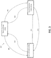
- FIG. 3 depicts a block diagram of a state diagram 300 in accordance with one or more embodiments of the present disclosure.
- the state diagram includes three states which the system can be in. Specifically, the system may be in a normal state 310, an accommodate state 320, and a control state 330.
- adjusting the state of an actuator of the system is based on a determination and collected signals. For example, adjusting the state from a normal state to a control state is done in response to a flag being greater than a flag current threshold value, a first load cell signal being greater than a measured value threshold, and a second load cell signal being greater than the measured value threshold (operation 306).
- adjusting the state from the control sate back to the normal state is done in response to the flag being less than the flag current threshold value, the first load cell signal being less than or equal to the measured value threshold, and the second load cell signal being less than or equal to the measured value threshold (operation 305).
- adjusting the state from a normal state to an accommodate state is done in response to the flag being greater than a flag current threshold value, the first load cell signal being between a first measured value threshold and a second measured value threshold, and the second load cell signal being between the first measured value threshold and the second measured value threshold (operation 301). Further, adjusting the state from the accommodate state back to the normal state is done in response to the flag being less than a flag current threshold value, the first load cell signal being less than or equal to the first measured value threshold, and the second load cell signal being less than or equal to the measured value threshold (operation 302).
- adjusting the state from a control state to an accommodate state is done in response to the flag being greater than a flag current threshold value, the first load cell signal being between a first measured value threshold and a second measured value threshold, and the second load cell signal being between the first measured value threshold and the second measured value threshold (operation 303). Further, adjusting the state from the accommodate state to the control state is done in response to the flag being greater than a flag current threshold value, the first load cell signal being greater than the second measured value threshold, and the second load cell signal being greater than the second measured value threshold (operation 304).
- FIG. 4 depicts a method 400 of fault detection and accommodation for a controller and actuator system in accordance with one or more embodiments of the present disclosure.
- the method 400 includes receiving, from a controller, a flag at an actuator in response to an excitation voltage and current falling below a threshold value (operation 405).
- the method 400 also includes engaging a sensor in the actuator in response to receiving the flag (operation 410).
- the method 400 includes receiving, using the sensor a first load cell signal and a second load cell signal in response to the sensor being engaged (operation 415) and determining how actuator is operating brake based on the received flag, first load cell signal, and second load cell signal (operation 420).
- the method 400 also includes adjusting a state of the actuator based on the determination (operation 425) and reporting the state of the actuator by transmitting a report signal to the controller (operation 430).
- FIG. 5 depicts additional operations for a particular portion of a method 500 of fault detection and accommodation for a controller and actuator system in accordance with one or more embodiments of the present disclosure.
- the particular portion of the method 500 includes generating the excitation voltage and current at the controller (operation 505) and transmitting the excitation voltage and current from the controller to the actuator (operation 510).
- the particular portion of the method 500 also includes receiving a response excitation voltage and current from the actuator at the controller (operation 515) and comparing the response excitation voltage and current against an expected voltage and current threshold value (operation 520). Further, the particular portion of the method 500 includes generating a flag when the response excitation voltage and current is below the expected voltage and current threshold value (operation 525), and transmitting the flag to the actuator (operation 530).
- the method 400 may further include receiving an excitation voltage and current at the actuator. Additionally, the method 400 may further include transmitting a response excitation voltage and current back to the controller. Further, according to another embodiment, the first load cell signal is a low side voltage signal, and the second load cell signal is a high side voltage signal.
- the controller used in the method 400 as shown in FIG. 4 may be an electric brake actuator controller (EBAC).
- the actuator may be an electric brake actuator (EBA)
- the EBAC may be connected to the actuator through a harnessing
- the harnessing can include a wire harness, a junction box, and a wire bundle assembly (WBA).
- the controller and actuator system comprises a plurality of actuators connected to the controller.
- a control loop within an EBAC may depend on several analog signals being received from the EBAs which can be transferred across nearly 30 m (100ft) of aircraft wiring in some cases.
- one of these signals may be a load cell force feedback whose magnitude is single millivolts full scale.
- a straight differential load cell feedback signal in a normal state, may be acceptable to use which is a typical operating state of a controller. If an interface becomes degraded via a shunt or series impedance, an excitation current flag may be set and a single ended measurements shifts up past a threshold which moves the control into an accommodation mode. In the accommodate mode the state machine calculates a gain correction of a differential feedback to reduce a force error applied by an actuator. If a load cell interface is degraded to a level of which the signal to noise ratio becomes problematic, the state machine switches to an alternate control state which reduces performance yet maintains function of a safety critical system.
- the present embodiments may be a system, a method, and/or a computer program product at any possible technical detail level of integration
- the computer program product may include a computer readable storage medium (or media) having computer readable program instructions thereon for causing a processor to carry out aspects of the present disclosure
- the computer readable storage medium can be a tangible device that can retain and store instructions for use by an instruction execution device.
- the computer readable storage medium may be, for example, but is not limited to, an electronic storage device, a magnetic storage device, an optical storage device, an electromagnetic storage device, a semiconductor storage device, or any suitable combination of the foregoing.
- a non-exhaustive list of more specific examples of the computer readable storage medium includes the following: a portable computer diskette, a hard disk, a random access memory (RAM), a read-only memory (ROM), an erasable programmable read-only memory (EPROM or Flash memory), a static random access memory (SRAM), a portable compact disc read-only memory (CD-ROM), a digital versatile disk (DVD), a memory stick, a floppy disk, a mechanically encoded device such as punch-cards or raised structures in a groove having instructions recorded thereon, and any suitable combination of the foregoing.
- RAM random access memory
- ROM read-only memory
- EPROM or Flash memory erasable programmable read-only memory
- SRAM static random access memory
- CD-ROM compact disc read-only memory
- DVD digital versatile disk
- memory stick a floppy disk
- a mechanically encoded device such as punch-cards or raised structures in a groove having instructions recorded thereon
- a computer readable storage medium is not to be construed as being transitory signals per se, such as radio waves or other freely propagating electromagnetic waves, electromagnetic waves propagating through a waveguide or other transmission media (e.g., light pulses passing through a fiber-optic cable), or electrical signals transmitted through a wire.
- Computer readable program instructions described herein can be downloaded to respective computing/processing devices from a computer readable storage medium or to an external computer or external storage device via a network, for example, the Internet, a local area network, a wide area network and/or a wireless network.
- the network may comprise copper transmission cables, optical transmission fibers, wireless transmission, routers, firewalls, switches, gateway computers and/or edge servers.
- a network adapter card or network interface in each computing/processing device receives computer readable program instructions from the network and forwards the computer readable program instructions for storage in a computer readable storage medium within the respective computing/processing device.
- Computer readable program instructions for carrying out operations of the present disclosure may be assembler instructions, instruction-set-architecture (ISA) instructions, machine instructions, machine dependent instructions, microcode, firmware instructions, state-setting data, configuration data for integrated circuitry, or either source code or object code written in any combination of one or more programming languages, including an object oriented programming language such as Java, Smalltalk, C++, or the like, and conventional procedural programming languages, such as the "C" programming language or similar programming languages.
- the computer readable program instructions may execute entirely on the user's computer, partly on the user's computer, as a stand-alone software package, partly on the user's computer and partly on a remote computer or entirely on the remote computer or server.
- the remote computer may be connected to the user's computer through any type of network, including a local area network (LAN) or a wide area network (WAN), or the connection may be made to an external computer (for example, through the Internet using an Internet Service Provider).
- electronic circuitry including, for example, programmable logic circuitry, field-programmable gate arrays (FPGA), or programmable logic arrays (PLA) may execute the computer readable program instructions by utilizing state information of the computer readable program instructions to personalize the electronic circuitry, in order to perform aspects of the present disclosure.
- These computer readable program instructions may be provided to a processor of a general purpose computer, special purpose computer, or other programmable data processing apparatus to produce a machine, such that the instructions, which execute via the processor of the computer or other programmable data processing apparatus, create means for implementing the functions/acts specified in the flowchart and/or block diagram block or blocks.
- These computer readable program instructions may also be stored in a computer readable storage medium that can direct a computer, a programmable data processing apparatus, and/or other devices to function in a particular manner, such that the computer readable storage medium having instructions stored therein comprises an article of manufacture including instructions which implement aspects of the function/act specified in the flowchart and/or block diagram block or blocks.
- the computer readable program instructions may also be loaded onto a computer, other programmable data processing apparatus, or other device to cause a series of operational steps to be performed on the computer, other programmable apparatus or other device to produce a computer implemented process, such that the instructions which execute on the computer, other programmable apparatus, or other device implement the functions/acts specified in the flowchart and/or block diagram block or blocks.
- each block in the flowchart or block diagrams may represent a module, segment, or portion of instructions, which comprises one or more executable instructions for implementing the specified logical function(s).
- the functions noted in the blocks may occur out of the order noted in the Figures.
- two blocks shown in succession may, in fact, be executed substantially concurrently, or the blocks may sometimes be executed in the reverse order, depending upon the functionality involved.
Landscapes
- Engineering & Computer Science (AREA)
- Transportation (AREA)
- Mechanical Engineering (AREA)
- Aviation & Aerospace Engineering (AREA)
- Valves And Accessory Devices For Braking Systems (AREA)
- Braking Systems And Boosters (AREA)
- Electric Propulsion And Braking For Vehicles (AREA)
Abstract
Description
- The subject matter disclosed herein generally relates to an electric brake actuator controller and, more particularly, to force feedback fault detection and accommodation for the electric brake actuator controller.
- Modem aircraft utilize electric motors in a multitude of applications; pumps, compressors, actuators, starters, etc. Many of these applications require the relatively sensitive drive electronics be located in an environmentally controlled electronic equipment bay. In contrast, the electric motor is remotely located elsewhere on the airframe. Often a significant distance exists between the drive electronics and the electric motor located elsewhere in the airframe. The reliability of this type of architecture is dependent on the airframe harnessing and its ability to deliver the signals between the drive electronics and the motor.
- One such system is an aircraft's electric brake (eBrake) that can include four or even eight actuators that are driven by a single drive electronic component such as an electric brake actuator controller (EBAC). The eBrake and the EBAC can be separated by roughly 100 feet of harness. Due to the number or parts and distance between them, failure detection of a fault that occurs at one of the actuators or in the harnessing can be difficult to detect accurately. Accordingly, there is a need to provide a system and method for improving the detection of system faults.
- According to one embodiment a method of fault detection and accommodation for a controller and actuator system is provided. The method includes receiving, from a controller, a flag at an actuator in response to an excitation voltage and current falling below a threshold value, engaging a sensor in the actuator in response to receiving the flag, receiving, using the sensor a first load cell signal and a second load cell signal in response to the sensor being engaged, determining how the actuator is operating the brake based on the received flag, first load cell signal, and second load cell signal, adjusting a state of the actuator based on the determination, and reporting the state of the actuator by transmitting a report signal to the controller.
- In addition to one or more of the features described above, or as an alternative, further embodiments may include receiving an excitation voltage and current at the actuator, and transmitting a response excitation voltage and current back to the controller.
- In addition to one or more of the features described above, or as an alternative, further embodiments may include receiving the flag at the actuator that includes generating the excitation voltage and current at the controller, transmitting the excitation voltage and current from the controller to the actuator, receiving a response excitation voltage and current from the actuator at the controller, comparing the response excitation voltage and current against an expected voltage and current threshold value, generating a flag when the response excitation voltage and current is below the expected voltage and current threshold value, and transmitting the flag to the actuator.
- In addition to one or more of the features described above, or as an alternative, further embodiments may include wherein the first load cell signal is a low side voltage signal, and wherein the second load cell signal is a high side voltage signal.
- In addition to one or more of the features described above, or as an alternative, further embodiments may include wherein adjusting the state of the actuator based on the determination includes adjusting the state from a normal state to a control state in response to the flag being greater than a flag current threshold value, the first load cell signal being greater than a measured value threshold, and the second load cell signal being greater than the measured value threshold, and adjusting the state from the control sate to the normal state in response to the flag being less than the flag current threshold value, the first load cell signal being less than or equal to the measured value threshold, and the second load cell signal being less than or equal to the measured value threshold.
- In addition to one or more of the features described above, or as an alternative, further embodiments may include wherein adjusting the state of the actuator based on the determination includes adjusting the state from a normal state to an accommodate state in response to the flag being greater than a flag current threshold value, the first load cell signal being between a first measured value threshold and a second measured value threshold, and the second load cell signal being between the first measured value threshold and the second measured value threshold, and adjusting the state from the accommodate state to the normal state in response to the flag being less than a flag current threshold value, the first load cell signal being less than or equal to the first measured value threshold, and the second load cell signal being less than or equal to the measured value threshold.
- In addition to one or more of the features described above, or as an alternative, further embodiments may include wherein adjusting the state of the actuator based on the determination includes adjusting the state from a control state to an accommodate state in response to the flag being greater than a flag current threshold value, the first load cell signal being between a first measured value threshold and a second measured value threshold, and the second load cell signal being between the first measured value threshold and the second measured value threshold, and adjusting the state from the accommodate state to the control state in response to the flag being greater than a flag current threshold value, the first load cell signal being greater than the second measured value threshold, and the second load cell signal being greater than the second measured value threshold.
- In addition to one or more of the features described above, or as an alternative, further embodiments may include wherein the controller is an electric brake actuator controller (EBAC), wherein the actuator is an electric brake actuator (EBA), wherein the EBAC is connected to the actuator through a harnessing, and wherein the harnessing includes a wire harness, a junction box, and a wire bundle assembly (WBA).
- In addition to one or more of the features described above, or as an alternative, further embodiments may include wherein the controller and actuator system includes a plurality of actuators connected to the controller.
- According to one embodiment a system for fault detection and accommodation is provided. The system includes a controller including a control processor that generates and transmits a flag and a storage medium that stores the flag, and a plurality of actuators connected to the controller using a harnessing, wherein each of the plurality of actuators includes at least one sensor, and wherein the plurality of actuators are configured to receive the flag in response to an excitation voltage and current falling below a threshold value, receive a first load cell signal and a second load cell signal using the at least one sensor, determine and adjust a state of the plurality of actuators based on the flag, the first load cell signal, and the second load cell signal, and report the state of the actuator to the controller.
- In addition to one or more of the features described above, or as an alternative, further embodiments may include wherein the controller is an electric brake actuator controller (EBAC), wherein the plurality of actuators are each electric brake actuators (EBA), wherein the EBAC is connected to the plurality of EBAs through the harnessing, and wherein the harnessing includes a wire harness, a junction box, and a wire bundle assembly (WBA).
- According to one embodiment a computer program product for fault detection and accommodation in a controller and an actuator system, the computer program product including a computer readable storage medium having program instructions embodied therewith is provided. The program instructions executable by a processor cause the processor to receive, from a controller, a flag at an actuator in response to an excitation voltage and current falling below a threshold value, engage a sensor in the actuator in response to receiving the flag, receive, using the sensor a first load cell signal and a second load cell signal in response to the sensor being engaged, determine how actuator is operating brake based on the received flag, first load cell signal, and second load cell signal, adjust a state of the actuator based on the determination, and report the state of the actuator by transmitting a report signal to the controller.
- In addition to one or more of the features described above, or as an alternative, further embodiments may include additional program instructions stored in the computer readable storage medium and executable by the processor to cause the processor to receive an excitation voltage and current at the actuator, and transmit a response excitation voltage and current back to the controller.
- In addition to one or more of the features described above, or as an alternative, further embodiments may include additional program instructions stored in the computer readable storage medium and executable by the processor to cause the processor to generate the excitation voltage and current at the controller, transmit the excitation voltage and current from the controller to the actuator, receive a response excitation voltage and current from the actuator at the controller, compare the response excitation voltage and current against an expected voltage and current threshold value, generate a flag when the response excitation voltage and current is below the expected voltage and current threshold value, and transmit the flag to the actuator.
- In addition to one or more of the features described above, or as an alternative, further embodiments may include wherein the first load cell signal is a low side voltage signal, and wherein the second load cell signal is a high side voltage signal.
- In addition to one or more of the features described above, or as an alternative, further embodiments may include additional program instructions stored in the computer readable storage medium and executable by the processor to cause the processor to adjust the state from a normal state to a control state in response to the flag being greater than a flag current threshold value, the first load cell signal being greater than a measured value threshold, and the second load cell signal being greater than the measured value threshold, and adjust the state from the control sate to the normal state in response to the flag being less than the flag current threshold value, the first load cell signal being less than or equal to the measured value threshold, and the second load cell signal being less than or equal to the measured value threshold.
- In addition to one or more of the features described above, or as an alternative, further embodiments may include additional program instructions stored in the computer readable storage medium and executable by the processor to cause the processor to adjust the state from a normal state to an accommodate state in response to the flag being greater than a flag current threshold value, the first load cell signal being between a first measured value threshold and a second measured value threshold, and the second load cell signal being between the first measured value threshold and the second measured value threshold, and adjust the state from the accommodate state to the normal state in response to the flag being less than a flag current threshold value, the first load cell signal being less than or equal to the first measured value threshold, and the second load cell signal being less than or equal to the measured value threshold.
- In addition to one or more of the features described above, or as an alternative, further embodiments may include additional program instructions stored in the computer readable storage medium and executable by the processor to cause the processor to adjust the state from a control state to an accommodate state in response to the flag being greater than a flag current threshold value, the first load cell signal being between a first measured value threshold and a second measured value threshold, and the second load cell signal being between the first measured value threshold and the second measured value threshold, and adjust the state from the accommodate state to the control state in response to the flag being greater than a flag current threshold value, the first load cell signal being greater than the second measured value threshold, and the second load cell signal being greater than the second measured value threshold.
- In addition to one or more of the features described above, or as an alternative, further embodiments may include wherein the controller is an electric brake actuator controller (EBAC), wherein the actuator is an electric brake actuator (EBA), wherein the EBAC is connected to the actuator through a harnessing, and wherein the harnessing includes a wire harness, a junction box, and a wire bundle assembly (WBA).
- In addition to one or more of the features described above, or as an alternative, further embodiments may include wherein the controller and actuator system includes a plurality of actuators connected to the controller.
- The foregoing features and elements may be combined in various combinations without exclusivity, unless expressly indicated otherwise. These features and elements as well as the operation thereof will become more apparent in light of the following description and the accompanying drawings. It should be understood, however, that the following description and drawings are intended to be illustrative and explanatory in nature and non-limiting.
- The foregoing and other features, and advantages of the present disclosure are apparent from the following detailed description taken in conjunction with the accompanying drawings in which:
-
FIG. 1A depicts a block diagram of a controller and actuator system in accordance with one or more embodiments of the present disclosure; -
FIG. 1B depicts a block diagram of a system with an electric break actuator controller (EBAC) and electric break actuator (EBA) in accordance with one or more embodiments of the present disclosure; -
FIG. 2 depicts a block diagram of an electric brake system of an aircraft that includes a controller and actuators in accordance with one or more embodiments of the present disclosure; -
FIG. 3 depicts a block diagram of a state diagram in accordance with one or more embodiments of the present disclosure; -
FIG. 4 depicts a method of fault detection and accommodation for a controller and actuator system in accordance with one or more embodiments of the present disclosure; and -
FIG. 5 depicts additional operations for a particular portion of a method of fault detection and accommodation for a controller and actuator system in accordance with one or more embodiments of the present disclosure. - As shown and described herein, various features of the disclosure will be presented. Various embodiments may have the same or similar features and thus the same or similar features may be labeled with the same reference numeral, but preceded by a different first number indicating the figure to which the feature is shown. Thus, for example, element "a" that is shown in FIG. X may be labeled "Xa" and a similar feature in FIG. Z may be labeled "Za." Although similar reference numbers may be used in a generic sense, various embodiments will be described and various features may include changes, alterations, modifications, etc. as will be appreciated by those of skill in the art, whether explicitly described or otherwise would be appreciated by those of skill in the art.
- Embodiments described herein are directed to a system and method that may help effectively detect and compensate for aircraft wiring faults within a controller and actuator system in order to increase dispatch reliability and reduce customer impact during a faulted condition. For example, one such system is an aircraft electric brake (eBrake) which includes an electric brake actuator controller (EBAC), aircraft wiring, a wire bundle assembly (WBA), and four or more electric brake actuators (EBA), as shown in
FIG. 2 . - Turning now to
FIG 1A , a block diagram of a controller andactuator system 100 in accordance with one or more embodiments of the present disclosure is shown. Thesystem 100 includes acontroller 110 that is connected to at least oneactuator 130. Thecontroller 110 is connected to theactuator 130 by a harnessing 120. The harnessing 120 electrically and communicatively connects thecontroller 110 andactuator 130. Theactuator 130 can further include asensor 131. Thecontroller 110 is able to generate and transmit signals to theactuator 130 which returns its own signals to thecontroller 110. The returned signals from theactuator 130 can be adjusted based on the feedback received from a connectedcomponent 140. Accordingly, the value of the returned signal can be used to derive information about how the actuator is powering thecomponent 140. Further, thesensor 131 in theactuator 130 can collect data that provides further details and information relating to thepowered component 140 and theactuator 130. The collected data from thesensor 131 and the feedback values and the adjusted voltage and current signals can all be transmitted back to thecontroller 110 which can aggregate and analyze these signals to determine what is going on in thesystem 100 and then can generate a flag signal. For example, according to one embodiment, the flag is set after a transmitted excitation current is sent out and then a returned excitation current is received that has dropped below a certain current threshold that indicates a flag should be transmitted. The flag signal can be transmitted to theactuator 130 which can use the flag to adjust and control thecomponent 140 in accordance with the controller's 110 analyzed understanding of the current state of the system. - Additionally, according to one or more embodiments, the
system 100 may include auser interface 150 that is connected to thecontroller 110 through a wired orwireless connection 151. The user interface is configured to display any collected data or signals received at or generated by thecontroller 110. For example, theuser interface 150 can display the returned voltage and current from theactuator 130 along with any sensor signals received from thesensor 131. Additionally, theuser interface 150 can display the initially transmitted signals sent from thecontroller 110 to theactuator 130. Further, theuser interface 150 can receive and transmit user input to thecontroller 110. Thecontroller 110 can in turn process the user input to determine what if any commands that user would like implemented. -
FIG. 1B depicts a block diagram of asystem 101 with an electric break actuator controller (EBAC) 115 and an electric break actuator (EBA) 135 in accordance with one or more embodiments of the present disclosure. - Specifically, the
system 101 includes the electric break actuator controller (EBAC) 115 that is connected to at least one electric break actuator (EBA) 135. The electric break actuator controller (EBAC) 115 is connected to theEBA 135 by a harnessing 125. The harnessing 125 electrically and communicatively connects theEBAC 115 andEBA 135. The harnessing 125 specifically includes awire harness 121, ajunction box 122, and a wire bundle assembly (WBA) 123. - Further, the
EBA 135 can further include asensor 131. TheEBAC 115 is able to generate and transmit signals to theEBA 135 which returns its own signals to theEBAC 115. The returned signals from theEBA 135 can be adjusted based on the feedback received from a connectedelectric break 145. For example, the a signal that defines the breaking force in pounds can be received from theelectric break 145 at theEBA 135. Accordingly, the value of the returned signal can be used to derive information about how theEBA 135 is powering theelectric break 145. Further, thesensor 131 in theEBA 135 can collect data that provides further details and information relating to theelectric break 145 and theEBA 135. The collected data from thesensor 131 and the feedback values and the adjusted voltage and current signals can all be transmitted back to theEBAC 115 which can aggregate and analyze these signals to determine what is going on in thesystem 101 and then can generate a flag signal. For example, according to one embodiment, the flag is generated and set after a transmitted excitation current is sent out and then a returned excitation current is received that has dropped below a certain current threshold that indicates a flag should be transmitted. The flag signal can be transmitted to theEBA 135 which can use the flag to adjust and control theelectric engine 145 in accordance with the EBAC's 115 analyzed understanding of the current state of thesystem 101. - Additionally, according to one or more embodiments, the
system 101 may include auser interface 150 that is connected to theEBAC 115 through a wired orwireless connection 151. The user interface is configured to display any collected data or signals received at or generated by theEBAC 115. For example, theuser interface 150 can display the returned voltage and current from theEBA 135 along with any sensor signals received from thesensor 131. Additionally, theuser interface 150 can display the initially transmitted signals sent from theEBAC 115 to theEBA 135. Further, theuser interface 150 can receive and transmit user input to theEBAC 115. TheEBAC 115 can in turn process the user input to determine what if any commands that user would like implemented. For example, theEBAC 115 can receive the user desired brake value that defines how much breaking force the user would like theelectric break 145 to apply to the aircraft within which thesystem 101 is located. -
FIG. 2 depicts a block diagram of anelectric brake system 200 of an aircraft that includes acontroller EBAC 210 andmultiple EBA actuators 230 in accordance with one or more embodiments of the present disclosure. As shown, thesystem 200 includes adata viewer 250 that is substantially similar to the user interfaces ofFIG. 1A and1B . Thesystem 200 also includes a harnessing 220 that includes awire harness 221, ajunction box 222, and a wire bundle assembly (WBA) 223. The harnessing connected theEBAC 210 and the plurality ofEBAs 230. Further, a number of signals can be transmitted through the system between the EBAC and EBAs as shown. -
FIG. 3 depicts a block diagram of a state diagram 300 in accordance with one or more embodiments of the present disclosure. The state diagram includes three states which the system can be in. Specifically, the system may be in anormal state 310, an accommodatestate 320, and acontrol state 330. Specifically, adjusting the state of an actuator of the system is based on a determination and collected signals. For example, adjusting the state from a normal state to a control state is done in response to a flag being greater than a flag current threshold value, a first load cell signal being greater than a measured value threshold, and a second load cell signal being greater than the measured value threshold (operation 306). Further, adjusting the state from the control sate back to the normal state is done in response to the flag being less than the flag current threshold value, the first load cell signal being less than or equal to the measured value threshold, and the second load cell signal being less than or equal to the measured value threshold (operation 305). - According to one or more embodiments, adjusting the state from a normal state to an accommodate state is done in response to the flag being greater than a flag current threshold value, the first load cell signal being between a first measured value threshold and a second measured value threshold, and the second load cell signal being between the first measured value threshold and the second measured value threshold (operation 301). Further, adjusting the state from the accommodate state back to the normal state is done in response to the flag being less than a flag current threshold value, the first load cell signal being less than or equal to the first measured value threshold, and the second load cell signal being less than or equal to the measured value threshold (operation 302).
- Further, according to one or more embodiments, adjusting the state from a control state to an accommodate state is done in response to the flag being greater than a flag current threshold value, the first load cell signal being between a first measured value threshold and a second measured value threshold, and the second load cell signal being between the first measured value threshold and the second measured value threshold (operation 303). Further, adjusting the state from the accommodate state to the control state is done in response to the flag being greater than a flag current threshold value, the first load cell signal being greater than the second measured value threshold, and the second load cell signal being greater than the second measured value threshold (operation 304).
-
FIG. 4 depicts amethod 400 of fault detection and accommodation for a controller and actuator system in accordance with one or more embodiments of the present disclosure. Themethod 400 includes receiving, from a controller, a flag at an actuator in response to an excitation voltage and current falling below a threshold value (operation 405). Themethod 400 also includes engaging a sensor in the actuator in response to receiving the flag (operation 410). Further, themethod 400 includes receiving, using the sensor a first load cell signal and a second load cell signal in response to the sensor being engaged (operation 415) and determining how actuator is operating brake based on the received flag, first load cell signal, and second load cell signal (operation 420). Themethod 400 also includes adjusting a state of the actuator based on the determination (operation 425) and reporting the state of the actuator by transmitting a report signal to the controller (operation 430). -
FIG. 5 depicts additional operations for a particular portion of amethod 500 of fault detection and accommodation for a controller and actuator system in accordance with one or more embodiments of the present disclosure. The particular portion of themethod 500 includes generating the excitation voltage and current at the controller (operation 505) and transmitting the excitation voltage and current from the controller to the actuator (operation 510). The particular portion of themethod 500 also includes receiving a response excitation voltage and current from the actuator at the controller (operation 515) and comparing the response excitation voltage and current against an expected voltage and current threshold value (operation 520). Further, the particular portion of themethod 500 includes generating a flag when the response excitation voltage and current is below the expected voltage and current threshold value (operation 525), and transmitting the flag to the actuator (operation 530). - According to one or more embodiments, the
method 400 may further include receiving an excitation voltage and current at the actuator. Additionally, themethod 400 may further include transmitting a response excitation voltage and current back to the controller. Further, according to another embodiment, the first load cell signal is a low side voltage signal, and the second load cell signal is a high side voltage signal. - According to one or more embodiments, the controller used in the
method 400 as shown inFIG. 4 may be an electric brake actuator controller (EBAC). Further, the actuator may be an electric brake actuator (EBA), the EBAC may be connected to the actuator through a harnessing, and the harnessing can include a wire harness, a junction box, and a wire bundle assembly (WBA). Further, according to an embodiments, the controller and actuator system comprises a plurality of actuators connected to the controller. - According to one or more embodiments, a control loop within an EBAC may depend on several analog signals being received from the EBAs which can be transferred across nearly 30 m (100ft) of aircraft wiring in some cases. For example, one of these signals may be a load cell force feedback whose magnitude is single millivolts full scale.
- According to one or more embodiments, in a normal state, a straight differential load cell feedback signal may be acceptable to use which is a typical operating state of a controller. If an interface becomes degraded via a shunt or series impedance, an excitation current flag may be set and a single ended measurements shifts up past a threshold which moves the control into an accommodation mode. In the accommodate mode the state machine calculates a gain correction of a differential feedback to reduce a force error applied by an actuator. If a load cell interface is degraded to a level of which the signal to noise ratio becomes problematic, the state machine switches to an alternate control state which reduces performance yet maintains function of a safety critical system.
- While the present disclosure has been described in detail in connection with only a limited number of embodiments, it should be readily understood that the present disclosure is not limited to such disclosed embodiments. Rather, the present disclosure can be modified to incorporate any number of variations, alterations, substitutions, combinations, sub-combinations, or equivalent arrangements not heretofore described, but which are commensurate with the scope of the present invention as defined by the claims. Additionally, while various embodiments of the present disclosure have been described, it is to be understood that aspects of the present disclosure may include only some of the described embodiments.
- The terminology used herein is for the purpose of describing particular embodiments only and is not intended to be limiting. As used herein, the singular forms "a", "an" and "the" are intended to include the plural forms as well, unless the context clearly indicates otherwise. It will be further understood that the terms "comprises" and/or "comprising," when used in this specification, specify the presence of stated features, integers, steps, operations, elements, and/or components, but do not preclude the presence or addition of one or more other features, integers, steps, operations, elements, components, and/or groups thereof.
- The corresponding structures, materials, acts, and equivalents of all means or step plus function elements in the claims below are intended to include any structure, material, or act for performing the function in combination with other claimed elements as specifically claimed. The description has been presented for purposes of illustration and description, but is not intended to be exhaustive or limited to the embodiments in the form disclosed. Many modifications and variations will be apparent to those of ordinary skill in the art without departing from the scope of the disclosure. The embodiments were chosen and described in order to best explain the principles of the disclosure and the practical application, and to enable others of ordinary skill in the art to understand various embodiments with various modifications as are suited to the particular use contemplated.
- The present embodiments may be a system, a method, and/or a computer program product at any possible technical detail level of integration. The computer program product may include a computer readable storage medium (or media) having computer readable program instructions thereon for causing a processor to carry out aspects of the present disclosure.
- The computer readable storage medium can be a tangible device that can retain and store instructions for use by an instruction execution device. The computer readable storage medium may be, for example, but is not limited to, an electronic storage device, a magnetic storage device, an optical storage device, an electromagnetic storage device, a semiconductor storage device, or any suitable combination of the foregoing. A non-exhaustive list of more specific examples of the computer readable storage medium includes the following: a portable computer diskette, a hard disk, a random access memory (RAM), a read-only memory (ROM), an erasable programmable read-only memory (EPROM or Flash memory), a static random access memory (SRAM), a portable compact disc read-only memory (CD-ROM), a digital versatile disk (DVD), a memory stick, a floppy disk, a mechanically encoded device such as punch-cards or raised structures in a groove having instructions recorded thereon, and any suitable combination of the foregoing. A computer readable storage medium, as used herein, is not to be construed as being transitory signals per se, such as radio waves or other freely propagating electromagnetic waves, electromagnetic waves propagating through a waveguide or other transmission media (e.g., light pulses passing through a fiber-optic cable), or electrical signals transmitted through a wire.
- Computer readable program instructions described herein can be downloaded to respective computing/processing devices from a computer readable storage medium or to an external computer or external storage device via a network, for example, the Internet, a local area network, a wide area network and/or a wireless network. The network may comprise copper transmission cables, optical transmission fibers, wireless transmission, routers, firewalls, switches, gateway computers and/or edge servers. A network adapter card or network interface in each computing/processing device receives computer readable program instructions from the network and forwards the computer readable program instructions for storage in a computer readable storage medium within the respective computing/processing device.
- Computer readable program instructions for carrying out operations of the present disclosure may be assembler instructions, instruction-set-architecture (ISA) instructions, machine instructions, machine dependent instructions, microcode, firmware instructions, state-setting data, configuration data for integrated circuitry, or either source code or object code written in any combination of one or more programming languages, including an object oriented programming language such as Java, Smalltalk, C++, or the like, and conventional procedural programming languages, such as the "C" programming language or similar programming languages. The computer readable program instructions may execute entirely on the user's computer, partly on the user's computer, as a stand-alone software package, partly on the user's computer and partly on a remote computer or entirely on the remote computer or server. In the latter scenario, the remote computer may be connected to the user's computer through any type of network, including a local area network (LAN) or a wide area network (WAN), or the connection may be made to an external computer (for example, through the Internet using an Internet Service Provider). In some embodiments, electronic circuitry including, for example, programmable logic circuitry, field-programmable gate arrays (FPGA), or programmable logic arrays (PLA) may execute the computer readable program instructions by utilizing state information of the computer readable program instructions to personalize the electronic circuitry, in order to perform aspects of the present disclosure.
- Aspects are described herein with reference to flowchart illustrations and/or block diagrams of methods, apparatus (systems), and computer program products according to embodiments. It will be understood that each block of the flowchart illustrations and/or block diagrams, and combinations of blocks in the flowchart illustrations and/or block diagrams, can be implemented by computer readable program instructions.
- These computer readable program instructions may be provided to a processor of a general purpose computer, special purpose computer, or other programmable data processing apparatus to produce a machine, such that the instructions, which execute via the processor of the computer or other programmable data processing apparatus, create means for implementing the functions/acts specified in the flowchart and/or block diagram block or blocks. These computer readable program instructions may also be stored in a computer readable storage medium that can direct a computer, a programmable data processing apparatus, and/or other devices to function in a particular manner, such that the computer readable storage medium having instructions stored therein comprises an article of manufacture including instructions which implement aspects of the function/act specified in the flowchart and/or block diagram block or blocks.
- The computer readable program instructions may also be loaded onto a computer, other programmable data processing apparatus, or other device to cause a series of operational steps to be performed on the computer, other programmable apparatus or other device to produce a computer implemented process, such that the instructions which execute on the computer, other programmable apparatus, or other device implement the functions/acts specified in the flowchart and/or block diagram block or blocks.
- The flowchart and block diagrams in the Figures illustrate the architecture, functionality, and operation of possible implementations of systems, methods, and computer program products according to various embodiments. In this regard, each block in the flowchart or block diagrams may represent a module, segment, or portion of instructions, which comprises one or more executable instructions for implementing the specified logical function(s). In some alternative implementations, the functions noted in the blocks may occur out of the order noted in the Figures. For example, two blocks shown in succession may, in fact, be executed substantially concurrently, or the blocks may sometimes be executed in the reverse order, depending upon the functionality involved. It will also be noted that each block of the block diagrams and/or flowchart illustration, and combinations of blocks in the block diagrams and/or flowchart illustration, can be implemented by special purpose hardware-based systems that perform the specified functions or acts or carry out combinations of special purpose hardware and computer instructions.
- The descriptions of the various embodiments have been presented for purposes of illustration, but are not intended to be exhaustive or limited to the embodiments disclosed. Many modifications and variations will be apparent to those of ordinary skill in the art without departing from the scope of the described invention as defined by the claims. The terminology used herein was chosen to best explain the principles of the embodiments, the practical application or technical improvement over technologies found in the marketplace, or to enable others of ordinary skill in the art to understand the embodiments disclosed herein.
- Accordingly, the present disclosure is not to be seen as limited by the foregoing description, but is only limited by the scope of the appended claims.
Claims (11)
- A method of fault detection and accommodation for a controller and actuator system, the method comprising:receiving, from a controller (110), a flag at an actuator (130) in response to an excitation voltage and current falling below a threshold value;engaging a sensor (131) in the actuator in response to receiving the flag;receiving, using the sensor a first load cell signal and a second load cell signal in response to the sensor being engaged;determining how actuator (130) is operating a brake based on the received flag, first load cell signal, and second load cell signal;adjusting a state of the actuator based on the determination; andreporting the state of the actuator by transmitting a report signal to the controller.
- The method of claim 1, further comprising:receiving an excitation voltage and current at the actuator; andtransmitting a response excitation voltage and current back to the controller.
- The method of claim 1, wherein receiving the flag at the actuator comprises:generating the excitation voltage and current at the controller;transmitting the excitation voltage and current from the controller to the actuator;receiving a response excitation voltage and current from the actuator at the controller;comparing the response excitation voltage and current against an expected voltage and current threshold value;generating a flag when the response excitation voltage and current is below the expected voltage and current threshold value; andtransmitting the flag to the actuator.
- The method of claim 1,
wherein the first load cell signal is a low side voltage signal, and
wherein the second load cell signal is a high side voltage signal. - The method of claim 1, wherein adjusting the state of the actuator based on the determination comprises:adjusting the state from a normal state to a control state in response to the flag being greater than a flag current threshold value, the first load cell signal being greater than a measured value threshold, and the second load cell signal being greater than the measured value threshold; andadjusting the state from the control sate to the normal state in response to the flag being less than the flag current threshold value, the first load cell signal being less than or equal to the measured value threshold, and the second load cell signal being less than or equal to the measured value threshold.
- The method of claim 1, wherein adjusting the state of the actuator based on the determination comprises:adjusting the state from a normal state to an accommodate state in response to the flag being greater than a flag current threshold value, the first load cell signal being between a first measured value threshold and a second measured value threshold, and the second load cell signal being between the first measured value threshold and the second measured value threshold; andadjusting the state from the accommodate state to the normal state in response to the flag being less than a flag current threshold value, the first load cell signal being less than or equal to the first measured value threshold, and the second load cell signal being less than or equal to the measured value threshold.
- The method of claim 1, wherein adjusting the state of the actuator based on the determination comprises:adjusting the state from a control state to an accommodate state in response to the flag being greater than a flag current threshold value, the first load cell signal being between a first measured value threshold and a second measured value threshold, and the second load cell signal being between the first measured value threshold and the second measured value threshold; andadjusting the state from the accommodate state to the control state in response to the flag being greater than a flag current threshold value, the first load cell signal being greater than the second measured value threshold, and the second load cell signal being greater than the second measured value threshold.
- The method of claim 1,
wherein the controller is an electric brake actuator controller (EBAC),
wherein the actuator is an electric brake actuator (EBA),
wherein the EBAC is connected to the actuator through a harnessing, and
wherein the harnessing comprises a wire harness, a junction box, and a wire bundle assembly (WBA). - The method of claim 1,
wherein the controller and actuator system comprises a plurality of actuators connected to the controller. - A system for fault detection and accommodation, the system comprising:a controller (115) comprising a control processor that generates and transmits a flag and a storage medium that stores the flag; anda plurality of actuators (135) connected to the controller using a harnessing (125),wherein each of the plurality of actuators comprises at least one sensor (131), andwherein the plurality of actuators are configured to receive the flag in response to an excitation voltage and current falling below a threshold value, receive a first load cell signal and a second load cell signal using the at least one sensor, determine and adjust a state of the plurality of actuators based on the flag, the first load cell signal, and the second load cell signal, and report the state of the actuator to the controller.
- The system of claim 10,
wherein the controller is an electric brake actuator controller (EBAC),
wherein the plurality of actuators are each electric brake actuators (EBA),
wherein the EBAC is connected to the plurality of EBAs through the harnessing, and
wherein the harnessing comprises a wire harness (121), a junction box (122), and a wire bundle assembly (WBA) (123).
Applications Claiming Priority (1)
| Application Number | Priority Date | Filing Date | Title |
|---|---|---|---|
| US15/075,956 US10427665B2 (en) | 2016-03-21 | 2016-03-21 | Force feedback fault detection and accommodation for a multi-channel electric brake actuator controller |
Publications (2)
| Publication Number | Publication Date |
|---|---|
| EP3235697A1 true EP3235697A1 (en) | 2017-10-25 |
| EP3235697B1 EP3235697B1 (en) | 2020-08-19 |
Family
ID=58709687
Family Applications (1)
| Application Number | Title | Priority Date | Filing Date |
|---|---|---|---|
| EP17161890.3A Active EP3235697B1 (en) | 2016-03-21 | 2017-03-20 | Force feedback fault detection and accommodation for a multi-channel electric brake actuator controller |
Country Status (4)
| Country | Link |
|---|---|
| US (1) | US10427665B2 (en) |
| EP (1) | EP3235697B1 (en) |
| BR (1) | BR102017005620B1 (en) |
| CA (1) | CA2961683C (en) |
Families Citing this family (3)
| Publication number | Priority date | Publication date | Assignee | Title |
|---|---|---|---|---|
| FR3095792B1 (en) * | 2019-05-06 | 2021-04-16 | Safran Landing Systems | Method of controlling an electric braking system and an aircraft electric braking system |
| CN113133042A (en) * | 2019-12-30 | 2021-07-16 | 中国移动通信集团四川有限公司 | Load fluctuation adjusting method, device, equipment and storage medium |
| US11970263B2 (en) | 2022-02-10 | 2024-04-30 | Goodrich Corporation | Hybrid brake systems and methods for load cell calibration |
Citations (7)
| Publication number | Priority date | Publication date | Assignee | Title |
|---|---|---|---|---|
| EP1686029A1 (en) * | 2005-01-27 | 2006-08-02 | Hitachi, Ltd. | Electrically powered brake system and control unit for electrically powered brake system |
| US20070084682A1 (en) * | 2001-07-31 | 2007-04-19 | Griffith T T | Parking brake adjustment for an aircraft having an electric brake system |
| US20080154470A1 (en) * | 2006-12-21 | 2008-06-26 | Goranson Pete T | System and methods for an electric brake actuation overdrive feature in an aircraft electric brake system |
| US20130338896A1 (en) * | 2010-12-17 | 2013-12-19 | Frank Baehrle-Miller | Method for setting the clamping force applied by a parking brake |
| US20150217748A1 (en) * | 2014-01-31 | 2015-08-06 | Messier-Bugatti-Dowty | Method for monitoring at least two electromechanical braking actuators |
| US9205560B1 (en) * | 2013-06-24 | 2015-12-08 | Redwood Robotics, Inc. | System and method for failure detection of a robot actuator |
| EP2965962A2 (en) * | 2014-07-07 | 2016-01-13 | Goodrich Corporation | Apparatus and system for power distribution to brake systems |
Family Cites Families (1)
| Publication number | Priority date | Publication date | Assignee | Title |
|---|---|---|---|---|
| US10093298B2 (en) * | 2016-01-08 | 2018-10-09 | Goodrich Corporation | Abnormal brake behavior detection |
-
2016
- 2016-03-21 US US15/075,956 patent/US10427665B2/en active Active
-
2017
- 2017-03-20 BR BR102017005620-1A patent/BR102017005620B1/en active IP Right Grant
- 2017-03-20 EP EP17161890.3A patent/EP3235697B1/en active Active
- 2017-03-20 CA CA2961683A patent/CA2961683C/en active Active
Patent Citations (7)
| Publication number | Priority date | Publication date | Assignee | Title |
|---|---|---|---|---|
| US20070084682A1 (en) * | 2001-07-31 | 2007-04-19 | Griffith T T | Parking brake adjustment for an aircraft having an electric brake system |
| EP1686029A1 (en) * | 2005-01-27 | 2006-08-02 | Hitachi, Ltd. | Electrically powered brake system and control unit for electrically powered brake system |
| US20080154470A1 (en) * | 2006-12-21 | 2008-06-26 | Goranson Pete T | System and methods for an electric brake actuation overdrive feature in an aircraft electric brake system |
| US20130338896A1 (en) * | 2010-12-17 | 2013-12-19 | Frank Baehrle-Miller | Method for setting the clamping force applied by a parking brake |
| US9205560B1 (en) * | 2013-06-24 | 2015-12-08 | Redwood Robotics, Inc. | System and method for failure detection of a robot actuator |
| US20150217748A1 (en) * | 2014-01-31 | 2015-08-06 | Messier-Bugatti-Dowty | Method for monitoring at least two electromechanical braking actuators |
| EP2965962A2 (en) * | 2014-07-07 | 2016-01-13 | Goodrich Corporation | Apparatus and system for power distribution to brake systems |
Also Published As
| Publication number | Publication date |
|---|---|
| CA2961683A1 (en) | 2017-09-21 |
| BR102017005620A2 (en) | 2017-09-26 |
| BR102017005620B1 (en) | 2023-05-09 |
| US20170267225A1 (en) | 2017-09-21 |
| EP3235697B1 (en) | 2020-08-19 |
| CA2961683C (en) | 2023-10-31 |
| US10427665B2 (en) | 2019-10-01 |
Similar Documents
| Publication | Publication Date | Title |
|---|---|---|
| CA2961683C (en) | Force feedback fault detection and accommodation for a multi-channel electric brake actuator controller | |
| CN107218961B (en) | Computer-implemented method for determining aircraft sensor faults and correcting aircraft sensor measurements in an aircraft system | |
| JP5875734B2 (en) | Diagnostic device and switching device for electric motor | |
| Izadi et al. | Supervisory algorithm based on reaction wheel modelling and spectrum analysis for detection and classification of electromechanical faults | |
| US10408877B2 (en) | Method and device for monitoring circuit breaker | |
| EP3223424A1 (en) | Motor drive, harness, and motor fault detection for a multi-channel electric brake actuator controller | |
| EP2362408A1 (en) | Safety switching device with universal signal input | |
| KR102104117B1 (en) | Diagnostic device of electric motor | |
| WO2015047121A1 (en) | Method and apparatus for embedded current signature analysis and remote condition monitoring for industrial machinery | |
| US20180165898A1 (en) | Rotorcraft structural fault-detection and isolation using virtual monitoring of loads | |
| KR102100488B1 (en) | How to monitor electromagnetic actuator type equipment | |
| KR102150872B1 (en) | Method and apparatuses for detecting failure of motor current sensor | |
| US20100052582A1 (en) | Method and arrangement for determining rotation speed of a motor | |
| EP3599716B1 (en) | Fault isolation for pulse width modulated three phase motor systems | |
| CN113739923A (en) | Power distribution cabinet fault monitoring method and system and vehicle | |
| US20160077161A1 (en) | Method for improved diagnostic in determining and preventing inverter faults | |
| US10713111B2 (en) | Damage detection system | |
| KR101576032B1 (en) | Method of hindance diagnose of electromotor | |
| EP3072019B1 (en) | Critical system and associated monitoring method | |
| KR20180104857A (en) | Apparatus and method for managing fault in electro hydraulic actuator | |
| US10866629B2 (en) | Power control for computer systems with multiple power supplies | |
| EP3260944B1 (en) | Device and method for machine monitoring | |
| JP6420984B2 (en) | Power conditioner, terminal device, and soundness confirmation method | |
| CN109932593B (en) | Method and apparatus for fault detection of electrical equipment | |
| JP7310156B2 (en) | Circuit breaker status diagnostic device, circuit breaker status diagnostic system, circuit breaker status diagnostic method, and program |
Legal Events
| Date | Code | Title | Description |
|---|---|---|---|
| PUAI | Public reference made under article 153(3) epc to a published international application that has entered the european phase |
Free format text: ORIGINAL CODE: 0009012 |
|
| STAA | Information on the status of an ep patent application or granted ep patent |
Free format text: STATUS: THE APPLICATION HAS BEEN PUBLISHED |
|
| AK | Designated contracting states |
Kind code of ref document: A1 Designated state(s): AL AT BE BG CH CY CZ DE DK EE ES FI FR GB GR HR HU IE IS IT LI LT LU LV MC MK MT NL NO PL PT RO RS SE SI SK SM TR |
|
| AX | Request for extension of the european patent |
Extension state: BA ME |
|
| STAA | Information on the status of an ep patent application or granted ep patent |
Free format text: STATUS: REQUEST FOR EXAMINATION WAS MADE |
|
| 17P | Request for examination filed |
Effective date: 20180425 |
|
| RBV | Designated contracting states (corrected) |
Designated state(s): AL AT BE BG CH CY CZ DE DK EE ES FI FR GB GR HR HU IE IS IT LI LT LU LV MC MK MT NL NO PL PT RO RS SE SI SK SM TR |
|
| GRAP | Despatch of communication of intention to grant a patent |
Free format text: ORIGINAL CODE: EPIDOSNIGR1 |
|
| STAA | Information on the status of an ep patent application or granted ep patent |
Free format text: STATUS: GRANT OF PATENT IS INTENDED |
|
| INTG | Intention to grant announced |
Effective date: 20200325 |
|
| GRAS | Grant fee paid |
Free format text: ORIGINAL CODE: EPIDOSNIGR3 |
|
| GRAA | (expected) grant |
Free format text: ORIGINAL CODE: 0009210 |
|
| STAA | Information on the status of an ep patent application or granted ep patent |
Free format text: STATUS: THE PATENT HAS BEEN GRANTED |
|
| AK | Designated contracting states |
Kind code of ref document: B1 Designated state(s): AL AT BE BG CH CY CZ DE DK EE ES FI FR GB GR HR HU IE IS IT LI LT LU LV MC MK MT NL NO PL PT RO RS SE SI SK SM TR |
|
| REG | Reference to a national code |
Ref country code: CH Ref legal event code: EP |
|
| REG | Reference to a national code |
Ref country code: DE Ref legal event code: R096 Ref document number: 602017021765 Country of ref document: DE |
|
| REG | Reference to a national code |
Ref country code: AT Ref legal event code: REF Ref document number: 1303609 Country of ref document: AT Kind code of ref document: T Effective date: 20200915 |
|
| REG | Reference to a national code |
Ref country code: IE Ref legal event code: FG4D |
|
| REG | Reference to a national code |
Ref country code: LT Ref legal event code: MG4D |
|
| REG | Reference to a national code |
Ref country code: NL Ref legal event code: MP Effective date: 20200819 |
|
| PG25 | Lapsed in a contracting state [announced via postgrant information from national office to epo] |
Ref country code: FI Free format text: LAPSE BECAUSE OF FAILURE TO SUBMIT A TRANSLATION OF THE DESCRIPTION OR TO PAY THE FEE WITHIN THE PRESCRIBED TIME-LIMIT Effective date: 20200819 Ref country code: GR Free format text: LAPSE BECAUSE OF FAILURE TO SUBMIT A TRANSLATION OF THE DESCRIPTION OR TO PAY THE FEE WITHIN THE PRESCRIBED TIME-LIMIT Effective date: 20201120 Ref country code: SE Free format text: LAPSE BECAUSE OF FAILURE TO SUBMIT A TRANSLATION OF THE DESCRIPTION OR TO PAY THE FEE WITHIN THE PRESCRIBED TIME-LIMIT Effective date: 20200819 Ref country code: BG Free format text: LAPSE BECAUSE OF FAILURE TO SUBMIT A TRANSLATION OF THE DESCRIPTION OR TO PAY THE FEE WITHIN THE PRESCRIBED TIME-LIMIT Effective date: 20201119 Ref country code: HR Free format text: LAPSE BECAUSE OF FAILURE TO SUBMIT A TRANSLATION OF THE DESCRIPTION OR TO PAY THE FEE WITHIN THE PRESCRIBED TIME-LIMIT Effective date: 20200819 Ref country code: NO Free format text: LAPSE BECAUSE OF FAILURE TO SUBMIT A TRANSLATION OF THE DESCRIPTION OR TO PAY THE FEE WITHIN THE PRESCRIBED TIME-LIMIT Effective date: 20201119 Ref country code: LT Free format text: LAPSE BECAUSE OF FAILURE TO SUBMIT A TRANSLATION OF THE DESCRIPTION OR TO PAY THE FEE WITHIN THE PRESCRIBED TIME-LIMIT Effective date: 20200819 Ref country code: PT Free format text: LAPSE BECAUSE OF FAILURE TO SUBMIT A TRANSLATION OF THE DESCRIPTION OR TO PAY THE FEE WITHIN THE PRESCRIBED TIME-LIMIT Effective date: 20201221 |
|
| REG | Reference to a national code |
Ref country code: AT Ref legal event code: MK05 Ref document number: 1303609 Country of ref document: AT Kind code of ref document: T Effective date: 20200819 |
|
| PG25 | Lapsed in a contracting state [announced via postgrant information from national office to epo] |
Ref country code: RS Free format text: LAPSE BECAUSE OF FAILURE TO SUBMIT A TRANSLATION OF THE DESCRIPTION OR TO PAY THE FEE WITHIN THE PRESCRIBED TIME-LIMIT Effective date: 20200819 Ref country code: LV Free format text: LAPSE BECAUSE OF FAILURE TO SUBMIT A TRANSLATION OF THE DESCRIPTION OR TO PAY THE FEE WITHIN THE PRESCRIBED TIME-LIMIT Effective date: 20200819 Ref country code: PL Free format text: LAPSE BECAUSE OF FAILURE TO SUBMIT A TRANSLATION OF THE DESCRIPTION OR TO PAY THE FEE WITHIN THE PRESCRIBED TIME-LIMIT Effective date: 20200819 Ref country code: NL Free format text: LAPSE BECAUSE OF FAILURE TO SUBMIT A TRANSLATION OF THE DESCRIPTION OR TO PAY THE FEE WITHIN THE PRESCRIBED TIME-LIMIT Effective date: 20200819 Ref country code: IS Free format text: LAPSE BECAUSE OF FAILURE TO SUBMIT A TRANSLATION OF THE DESCRIPTION OR TO PAY THE FEE WITHIN THE PRESCRIBED TIME-LIMIT Effective date: 20201219 |
|
| PG25 | Lapsed in a contracting state [announced via postgrant information from national office to epo] |
Ref country code: EE Free format text: LAPSE BECAUSE OF FAILURE TO SUBMIT A TRANSLATION OF THE DESCRIPTION OR TO PAY THE FEE WITHIN THE PRESCRIBED TIME-LIMIT Effective date: 20200819 Ref country code: SM Free format text: LAPSE BECAUSE OF FAILURE TO SUBMIT A TRANSLATION OF THE DESCRIPTION OR TO PAY THE FEE WITHIN THE PRESCRIBED TIME-LIMIT Effective date: 20200819 Ref country code: RO Free format text: LAPSE BECAUSE OF FAILURE TO SUBMIT A TRANSLATION OF THE DESCRIPTION OR TO PAY THE FEE WITHIN THE PRESCRIBED TIME-LIMIT Effective date: 20200819 Ref country code: CZ Free format text: LAPSE BECAUSE OF FAILURE TO SUBMIT A TRANSLATION OF THE DESCRIPTION OR TO PAY THE FEE WITHIN THE PRESCRIBED TIME-LIMIT Effective date: 20200819 Ref country code: DK Free format text: LAPSE BECAUSE OF FAILURE TO SUBMIT A TRANSLATION OF THE DESCRIPTION OR TO PAY THE FEE WITHIN THE PRESCRIBED TIME-LIMIT Effective date: 20200819 |
|
| REG | Reference to a national code |
Ref country code: DE Ref legal event code: R097 Ref document number: 602017021765 Country of ref document: DE |
|
| PG25 | Lapsed in a contracting state [announced via postgrant information from national office to epo] |
Ref country code: ES Free format text: LAPSE BECAUSE OF FAILURE TO SUBMIT A TRANSLATION OF THE DESCRIPTION OR TO PAY THE FEE WITHIN THE PRESCRIBED TIME-LIMIT Effective date: 20200819 Ref country code: AL Free format text: LAPSE BECAUSE OF FAILURE TO SUBMIT A TRANSLATION OF THE DESCRIPTION OR TO PAY THE FEE WITHIN THE PRESCRIBED TIME-LIMIT Effective date: 20200819 Ref country code: AT Free format text: LAPSE BECAUSE OF FAILURE TO SUBMIT A TRANSLATION OF THE DESCRIPTION OR TO PAY THE FEE WITHIN THE PRESCRIBED TIME-LIMIT Effective date: 20200819 |
|
| PLBE | No opposition filed within time limit |
Free format text: ORIGINAL CODE: 0009261 |
|
| STAA | Information on the status of an ep patent application or granted ep patent |
Free format text: STATUS: NO OPPOSITION FILED WITHIN TIME LIMIT |
|
| PG25 | Lapsed in a contracting state [announced via postgrant information from national office to epo] |
Ref country code: SK Free format text: LAPSE BECAUSE OF FAILURE TO SUBMIT A TRANSLATION OF THE DESCRIPTION OR TO PAY THE FEE WITHIN THE PRESCRIBED TIME-LIMIT Effective date: 20200819 |
|
| 26N | No opposition filed |
Effective date: 20210520 |
|
| PG25 | Lapsed in a contracting state [announced via postgrant information from national office to epo] |
Ref country code: IT Free format text: LAPSE BECAUSE OF FAILURE TO SUBMIT A TRANSLATION OF THE DESCRIPTION OR TO PAY THE FEE WITHIN THE PRESCRIBED TIME-LIMIT Effective date: 20200819 |
|
| PG25 | Lapsed in a contracting state [announced via postgrant information from national office to epo] |
Ref country code: SI Free format text: LAPSE BECAUSE OF FAILURE TO SUBMIT A TRANSLATION OF THE DESCRIPTION OR TO PAY THE FEE WITHIN THE PRESCRIBED TIME-LIMIT Effective date: 20200819 |
|
| PG25 | Lapsed in a contracting state [announced via postgrant information from national office to epo] |
Ref country code: MC Free format text: LAPSE BECAUSE OF FAILURE TO SUBMIT A TRANSLATION OF THE DESCRIPTION OR TO PAY THE FEE WITHIN THE PRESCRIBED TIME-LIMIT Effective date: 20200819 |
|
| REG | Reference to a national code |
Ref country code: CH Ref legal event code: PL |
|
| REG | Reference to a national code |
Ref country code: BE Ref legal event code: MM Effective date: 20210331 |
|
| PG25 | Lapsed in a contracting state [announced via postgrant information from national office to epo] |
Ref country code: CH Free format text: LAPSE BECAUSE OF NON-PAYMENT OF DUE FEES Effective date: 20210331 Ref country code: LI Free format text: LAPSE BECAUSE OF NON-PAYMENT OF DUE FEES Effective date: 20210331 Ref country code: LU Free format text: LAPSE BECAUSE OF NON-PAYMENT OF DUE FEES Effective date: 20210320 Ref country code: IE Free format text: LAPSE BECAUSE OF NON-PAYMENT OF DUE FEES Effective date: 20210320 |
|
| PG25 | Lapsed in a contracting state [announced via postgrant information from national office to epo] |
Ref country code: BE Free format text: LAPSE BECAUSE OF NON-PAYMENT OF DUE FEES Effective date: 20210331 |
|
| PGFP | Annual fee paid to national office [announced via postgrant information from national office to epo] |
Ref country code: FR Payment date: 20230222 Year of fee payment: 7 |
|
| PG25 | Lapsed in a contracting state [announced via postgrant information from national office to epo] |
Ref country code: HU Free format text: LAPSE BECAUSE OF FAILURE TO SUBMIT A TRANSLATION OF THE DESCRIPTION OR TO PAY THE FEE WITHIN THE PRESCRIBED TIME-LIMIT; INVALID AB INITIO Effective date: 20170320 |
|
| PG25 | Lapsed in a contracting state [announced via postgrant information from national office to epo] |
Ref country code: CY Free format text: LAPSE BECAUSE OF FAILURE TO SUBMIT A TRANSLATION OF THE DESCRIPTION OR TO PAY THE FEE WITHIN THE PRESCRIBED TIME-LIMIT Effective date: 20200819 |
|
| PG25 | Lapsed in a contracting state [announced via postgrant information from national office to epo] |
Ref country code: MK Free format text: LAPSE BECAUSE OF FAILURE TO SUBMIT A TRANSLATION OF THE DESCRIPTION OR TO PAY THE FEE WITHIN THE PRESCRIBED TIME-LIMIT Effective date: 20200819 |
|
| PGFP | Annual fee paid to national office [announced via postgrant information from national office to epo] |
Ref country code: DE Payment date: 20240220 Year of fee payment: 8 Ref country code: GB Payment date: 20240221 Year of fee payment: 8 |