EP3229696B1 - Patientenaufklärung für perkutane koronarinterventionsbehandlungen - Google Patents
Patientenaufklärung für perkutane koronarinterventionsbehandlungen Download PDFInfo
- Publication number
- EP3229696B1 EP3229696B1 EP15805628.3A EP15805628A EP3229696B1 EP 3229696 B1 EP3229696 B1 EP 3229696B1 EP 15805628 A EP15805628 A EP 15805628A EP 3229696 B1 EP3229696 B1 EP 3229696B1
- Authority
- EP
- European Patent Office
- Prior art keywords
- vessel
- image
- display
- patient
- instrument
- Prior art date
- Legal status (The legal status is an assumption and is not a legal conclusion. Google has not performed a legal analysis and makes no representation as to the accuracy of the status listed.)
- Active
Links
- 238000011282 treatment Methods 0.000 title claims description 69
- 238000013146 percutaneous coronary intervention Methods 0.000 title description 6
- 238000012545 processing Methods 0.000 claims description 57
- 208000031481 Pathologic Constriction Diseases 0.000 claims description 47
- 208000037804 stenosis Diseases 0.000 claims description 47
- 230000036262 stenosis Effects 0.000 claims description 47
- 238000012800 visualization Methods 0.000 claims description 47
- 238000009530 blood pressure measurement Methods 0.000 claims description 29
- 238000004891 communication Methods 0.000 claims description 27
- 230000000007 visual effect Effects 0.000 claims description 16
- 238000012014 optical coherence tomography Methods 0.000 claims description 15
- 238000002608 intravascular ultrasound Methods 0.000 claims description 11
- 238000002591 computed tomography Methods 0.000 claims description 10
- 244000208734 Pisonia aculeata Species 0.000 claims description 4
- 230000000747 cardiac effect Effects 0.000 claims description 3
- 238000002399 angioplasty Methods 0.000 claims description 2
- 239000008177 pharmaceutical agent Substances 0.000 claims description 2
- 238000000034 method Methods 0.000 description 72
- 239000012530 fluid Substances 0.000 description 26
- 238000012544 monitoring process Methods 0.000 description 21
- 238000003384 imaging method Methods 0.000 description 14
- 230000008867 communication pathway Effects 0.000 description 10
- 238000002405 diagnostic procedure Methods 0.000 description 9
- 230000000875 corresponding effect Effects 0.000 description 8
- 230000008569 process Effects 0.000 description 8
- 230000003287 optical effect Effects 0.000 description 7
- 238000003860 storage Methods 0.000 description 7
- 238000004458 analytical method Methods 0.000 description 6
- 230000006855 networking Effects 0.000 description 5
- 210000004351 coronary vessel Anatomy 0.000 description 4
- 238000005259 measurement Methods 0.000 description 4
- 238000004088 simulation Methods 0.000 description 4
- CCEKAJIANROZEO-UHFFFAOYSA-N sulfluramid Chemical group CCNS(=O)(=O)C(F)(F)C(F)(F)C(F)(F)C(F)(F)C(F)(F)C(F)(F)C(F)(F)C(F)(F)F CCEKAJIANROZEO-UHFFFAOYSA-N 0.000 description 4
- 238000001356 surgical procedure Methods 0.000 description 4
- 238000002604 ultrasonography Methods 0.000 description 4
- 238000002583 angiography Methods 0.000 description 3
- 230000008901 benefit Effects 0.000 description 3
- 210000004204 blood vessel Anatomy 0.000 description 3
- 230000008859 change Effects 0.000 description 3
- 230000000670 limiting effect Effects 0.000 description 3
- 230000036961 partial effect Effects 0.000 description 3
- 208000007536 Thrombosis Diseases 0.000 description 2
- 210000000709 aorta Anatomy 0.000 description 2
- 238000013459 approach Methods 0.000 description 2
- 230000004872 arterial blood pressure Effects 0.000 description 2
- 238000013475 authorization Methods 0.000 description 2
- 230000005540 biological transmission Effects 0.000 description 2
- 239000008280 blood Substances 0.000 description 2
- 210000004369 blood Anatomy 0.000 description 2
- 230000001276 controlling effect Effects 0.000 description 2
- 230000003247 decreasing effect Effects 0.000 description 2
- 238000003745 diagnosis Methods 0.000 description 2
- 238000010586 diagram Methods 0.000 description 2
- 230000000004 hemodynamic effect Effects 0.000 description 2
- 230000023597 hemostasis Effects 0.000 description 2
- 230000003902 lesion Effects 0.000 description 2
- 238000004519 manufacturing process Methods 0.000 description 2
- 239000000203 mixture Substances 0.000 description 2
- 230000002093 peripheral effect Effects 0.000 description 2
- 239000013316 polymer of intrinsic microporosity Substances 0.000 description 2
- APTZNLHMIGJTEW-UHFFFAOYSA-N pyraflufen-ethyl Chemical compound C1=C(Cl)C(OCC(=O)OCC)=CC(C=2C(=C(OC(F)F)N(C)N=2)Cl)=C1F APTZNLHMIGJTEW-UHFFFAOYSA-N 0.000 description 2
- 230000002829 reductive effect Effects 0.000 description 2
- 238000009877 rendering Methods 0.000 description 2
- 239000004065 semiconductor Substances 0.000 description 2
- 238000002560 therapeutic procedure Methods 0.000 description 2
- 229920001621 AMOLED Polymers 0.000 description 1
- OYPRJOBELJOOCE-UHFFFAOYSA-N Calcium Chemical compound [Ca] OYPRJOBELJOOCE-UHFFFAOYSA-N 0.000 description 1
- RYGMFSIKBFXOCR-UHFFFAOYSA-N Copper Chemical compound [Cu] RYGMFSIKBFXOCR-UHFFFAOYSA-N 0.000 description 1
- 208000005189 Embolism Diseases 0.000 description 1
- 208000000913 Kidney Calculi Diseases 0.000 description 1
- 206010028980 Neoplasm Diseases 0.000 description 1
- 206010029148 Nephrolithiasis Diseases 0.000 description 1
- 241001422033 Thestylus Species 0.000 description 1
- 238000010317 ablation therapy Methods 0.000 description 1
- 230000004075 alteration Effects 0.000 description 1
- 210000003484 anatomy Anatomy 0.000 description 1
- 229910052791 calcium Inorganic materials 0.000 description 1
- 239000011575 calcium Substances 0.000 description 1
- 230000001413 cellular effect Effects 0.000 description 1
- 239000003795 chemical substances by application Substances 0.000 description 1
- 230000001427 coherent effect Effects 0.000 description 1
- 239000003086 colorant Substances 0.000 description 1
- 238000007596 consolidation process Methods 0.000 description 1
- 229910052802 copper Inorganic materials 0.000 description 1
- 239000010949 copper Substances 0.000 description 1
- 230000002596 correlated effect Effects 0.000 description 1
- 238000002574 cystoscopy Methods 0.000 description 1
- 238000013481 data capture Methods 0.000 description 1
- 238000013480 data collection Methods 0.000 description 1
- 230000007423 decrease Effects 0.000 description 1
- 230000001419 dependent effect Effects 0.000 description 1
- 201000010099 disease Diseases 0.000 description 1
- 208000037265 diseases, disorders, signs and symptoms Diseases 0.000 description 1
- 229940079593 drug Drugs 0.000 description 1
- 239000003814 drug Substances 0.000 description 1
- 238000002592 echocardiography Methods 0.000 description 1
- 238000005516 engineering process Methods 0.000 description 1
- 238000011156 evaluation Methods 0.000 description 1
- 239000000835 fiber Substances 0.000 description 1
- 238000002594 fluoroscopy Methods 0.000 description 1
- 230000036541 health Effects 0.000 description 1
- 230000000544 hyperemic effect Effects 0.000 description 1
- 230000003116 impacting effect Effects 0.000 description 1
- 230000010354 integration Effects 0.000 description 1
- 210000003141 lower extremity Anatomy 0.000 description 1
- 238000007726 management method Methods 0.000 description 1
- 239000000463 material Substances 0.000 description 1
- 230000007246 mechanism Effects 0.000 description 1
- 229910052751 metal Inorganic materials 0.000 description 1
- 239000002184 metal Substances 0.000 description 1
- 238000012986 modification Methods 0.000 description 1
- 230000004048 modification Effects 0.000 description 1
- 230000000877 morphologic effect Effects 0.000 description 1
- 230000001338 necrotic effect Effects 0.000 description 1
- 230000035479 physiological effects, processes and functions Effects 0.000 description 1
- 230000001737 promoting effect Effects 0.000 description 1
- 238000005096 rolling process Methods 0.000 description 1
- 239000000523 sample Substances 0.000 description 1
- 230000035807 sensation Effects 0.000 description 1
- 230000035945 sensitivity Effects 0.000 description 1
- 239000007787 solid Substances 0.000 description 1
- 230000003068 static effect Effects 0.000 description 1
- 239000000126 substance Substances 0.000 description 1
- 230000001360 synchronised effect Effects 0.000 description 1
- 238000012360 testing method Methods 0.000 description 1
- 229920001169 thermoplastic Polymers 0.000 description 1
- 229920001187 thermosetting polymer Polymers 0.000 description 1
- 239000004416 thermosoftening plastic Substances 0.000 description 1
- 238000013175 transesophageal echocardiography Methods 0.000 description 1
- 230000002792 vascular Effects 0.000 description 1
- 208000019553 vascular disease Diseases 0.000 description 1
- 210000005166 vasculature Anatomy 0.000 description 1
Images


Classifications
-
- A—HUMAN NECESSITIES
- A61—MEDICAL OR VETERINARY SCIENCE; HYGIENE
- A61B—DIAGNOSIS; SURGERY; IDENTIFICATION
- A61B6/00—Apparatus for radiation diagnosis, e.g. combined with radiation therapy equipment
- A61B6/50—Clinical applications
- A61B6/504—Clinical applications involving diagnosis of blood vessels, e.g. by angiography
-
- A—HUMAN NECESSITIES
- A61—MEDICAL OR VETERINARY SCIENCE; HYGIENE
- A61B—DIAGNOSIS; SURGERY; IDENTIFICATION
- A61B5/00—Measuring for diagnostic purposes; Identification of persons
- A61B5/02—Detecting, measuring or recording pulse, heart rate, blood pressure or blood flow; Combined pulse/heart-rate/blood pressure determination; Evaluating a cardiovascular condition not otherwise provided for, e.g. using combinations of techniques provided for in this group with electrocardiography or electroauscultation; Heart catheters for measuring blood pressure
- A61B5/021—Measuring pressure in heart or blood vessels
- A61B5/0215—Measuring pressure in heart or blood vessels by means inserted into the body
-
- A—HUMAN NECESSITIES
- A61—MEDICAL OR VETERINARY SCIENCE; HYGIENE
- A61B—DIAGNOSIS; SURGERY; IDENTIFICATION
- A61B5/00—Measuring for diagnostic purposes; Identification of persons
- A61B5/68—Arrangements of detecting, measuring or recording means, e.g. sensors, in relation to patient
- A61B5/6846—Arrangements of detecting, measuring or recording means, e.g. sensors, in relation to patient specially adapted to be brought in contact with an internal body part, i.e. invasive
- A61B5/6847—Arrangements of detecting, measuring or recording means, e.g. sensors, in relation to patient specially adapted to be brought in contact with an internal body part, i.e. invasive mounted on an invasive device
- A61B5/6851—Guide wires
-
- A—HUMAN NECESSITIES
- A61—MEDICAL OR VETERINARY SCIENCE; HYGIENE
- A61B—DIAGNOSIS; SURGERY; IDENTIFICATION
- A61B5/00—Measuring for diagnostic purposes; Identification of persons
- A61B5/68—Arrangements of detecting, measuring or recording means, e.g. sensors, in relation to patient
- A61B5/6846—Arrangements of detecting, measuring or recording means, e.g. sensors, in relation to patient specially adapted to be brought in contact with an internal body part, i.e. invasive
- A61B5/6847—Arrangements of detecting, measuring or recording means, e.g. sensors, in relation to patient specially adapted to be brought in contact with an internal body part, i.e. invasive mounted on an invasive device
- A61B5/6852—Catheters
-
- A—HUMAN NECESSITIES
- A61—MEDICAL OR VETERINARY SCIENCE; HYGIENE
- A61B—DIAGNOSIS; SURGERY; IDENTIFICATION
- A61B6/00—Apparatus for radiation diagnosis, e.g. combined with radiation therapy equipment
- A61B6/02—Devices for diagnosis sequentially in different planes; Stereoscopic radiation diagnosis
- A61B6/03—Computerised tomographs
- A61B6/032—Transmission computed tomography [CT]
-
- A—HUMAN NECESSITIES
- A61—MEDICAL OR VETERINARY SCIENCE; HYGIENE
- A61B—DIAGNOSIS; SURGERY; IDENTIFICATION
- A61B6/00—Apparatus for radiation diagnosis, e.g. combined with radiation therapy equipment
- A61B6/44—Constructional features of apparatus for radiation diagnosis
- A61B6/4417—Constructional features of apparatus for radiation diagnosis related to combined acquisition of different diagnostic modalities
-
- A—HUMAN NECESSITIES
- A61—MEDICAL OR VETERINARY SCIENCE; HYGIENE
- A61B—DIAGNOSIS; SURGERY; IDENTIFICATION
- A61B6/00—Apparatus for radiation diagnosis, e.g. combined with radiation therapy equipment
- A61B6/46—Apparatus for radiation diagnosis, e.g. combined with radiation therapy equipment with special arrangements for interfacing with the operator or the patient
- A61B6/461—Displaying means of special interest
-
- A—HUMAN NECESSITIES
- A61—MEDICAL OR VETERINARY SCIENCE; HYGIENE
- A61B—DIAGNOSIS; SURGERY; IDENTIFICATION
- A61B8/00—Diagnosis using ultrasonic, sonic or infrasonic waves
- A61B8/04—Measuring blood pressure
-
- A—HUMAN NECESSITIES
- A61—MEDICAL OR VETERINARY SCIENCE; HYGIENE
- A61B—DIAGNOSIS; SURGERY; IDENTIFICATION
- A61B8/00—Diagnosis using ultrasonic, sonic or infrasonic waves
- A61B8/08—Detecting organic movements or changes, e.g. tumours, cysts, swellings
- A61B8/0891—Detecting organic movements or changes, e.g. tumours, cysts, swellings for diagnosis of blood vessels
-
- A—HUMAN NECESSITIES
- A61—MEDICAL OR VETERINARY SCIENCE; HYGIENE
- A61B—DIAGNOSIS; SURGERY; IDENTIFICATION
- A61B8/00—Diagnosis using ultrasonic, sonic or infrasonic waves
- A61B8/12—Diagnosis using ultrasonic, sonic or infrasonic waves in body cavities or body tracts, e.g. by using catheters
-
- A—HUMAN NECESSITIES
- A61—MEDICAL OR VETERINARY SCIENCE; HYGIENE
- A61B—DIAGNOSIS; SURGERY; IDENTIFICATION
- A61B90/00—Instruments, implements or accessories specially adapted for surgery or diagnosis and not covered by any of the groups A61B1/00 - A61B50/00, e.g. for luxation treatment or for protecting wound edges
- A61B90/36—Image-producing devices or illumination devices not otherwise provided for
- A61B90/37—Surgical systems with images on a monitor during operation
-
- G—PHYSICS
- G16—INFORMATION AND COMMUNICATION TECHNOLOGY [ICT] SPECIALLY ADAPTED FOR SPECIFIC APPLICATION FIELDS
- G16H—HEALTHCARE INFORMATICS, i.e. INFORMATION AND COMMUNICATION TECHNOLOGY [ICT] SPECIALLY ADAPTED FOR THE HANDLING OR PROCESSING OF MEDICAL OR HEALTHCARE DATA
- G16H50/00—ICT specially adapted for medical diagnosis, medical simulation or medical data mining; ICT specially adapted for detecting, monitoring or modelling epidemics or pandemics
- G16H50/20—ICT specially adapted for medical diagnosis, medical simulation or medical data mining; ICT specially adapted for detecting, monitoring or modelling epidemics or pandemics for computer-aided diagnosis, e.g. based on medical expert systems
-
- A—HUMAN NECESSITIES
- A61—MEDICAL OR VETERINARY SCIENCE; HYGIENE
- A61B—DIAGNOSIS; SURGERY; IDENTIFICATION
- A61B34/00—Computer-aided surgery; Manipulators or robots specially adapted for use in surgery
- A61B34/10—Computer-aided planning, simulation or modelling of surgical operations
- A61B2034/101—Computer-aided simulation of surgical operations
- A61B2034/102—Modelling of surgical devices, implants or prosthesis
-
- A—HUMAN NECESSITIES
- A61—MEDICAL OR VETERINARY SCIENCE; HYGIENE
- A61B—DIAGNOSIS; SURGERY; IDENTIFICATION
- A61B34/00—Computer-aided surgery; Manipulators or robots specially adapted for use in surgery
- A61B34/10—Computer-aided planning, simulation or modelling of surgical operations
- A61B2034/107—Visualisation of planned trajectories or target regions
-
- A—HUMAN NECESSITIES
- A61—MEDICAL OR VETERINARY SCIENCE; HYGIENE
- A61B—DIAGNOSIS; SURGERY; IDENTIFICATION
- A61B90/00—Instruments, implements or accessories specially adapted for surgery or diagnosis and not covered by any of the groups A61B1/00 - A61B50/00, e.g. for luxation treatment or for protecting wound edges
- A61B90/36—Image-producing devices or illumination devices not otherwise provided for
- A61B90/37—Surgical systems with images on a monitor during operation
- A61B2090/373—Surgical systems with images on a monitor during operation using light, e.g. by using optical scanners
- A61B2090/3735—Optical coherence tomography [OCT]
-
- A—HUMAN NECESSITIES
- A61—MEDICAL OR VETERINARY SCIENCE; HYGIENE
- A61F—FILTERS IMPLANTABLE INTO BLOOD VESSELS; PROSTHESES; DEVICES PROVIDING PATENCY TO, OR PREVENTING COLLAPSING OF, TUBULAR STRUCTURES OF THE BODY, e.g. STENTS; ORTHOPAEDIC, NURSING OR CONTRACEPTIVE DEVICES; FOMENTATION; TREATMENT OR PROTECTION OF EYES OR EARS; BANDAGES, DRESSINGS OR ABSORBENT PADS; FIRST-AID KITS
- A61F2/00—Filters implantable into blood vessels; Prostheses, i.e. artificial substitutes or replacements for parts of the body; Appliances for connecting them with the body; Devices providing patency to, or preventing collapsing of, tubular structures of the body, e.g. stents
- A61F2/95—Instruments specially adapted for placement or removal of stents or stent-grafts
Definitions
- the present disclosure relates generally to a system for identifying and presenting cardiac treatment options.
- IVUS intravascular ultrasound
- FL-IVUS forward looking IVUS
- FFR fractional flow reserve
- iFR instant wave-free ratio
- CFR coronary flow reserve
- OCT optical coherence tomography
- a patient is required to undergo several procedures before receiving actual treatments.
- a patient with circulatory problems may undergo a diagnostic procedure such as an angiogram. After data from the angiogram is compiled and analyzed by a physician, the physician meets with the patient to discuss treatment options. After an initial diagnosis, the patient may be required to undergo additional testing such as an FFR, iFR, or CFR determination.
- a physician may outline a recommended surgical procedure. Patients often want to discuss options with their families before undergoing surgery, adding additional time between treatments. This typical multiple-treatment arrangement not only inconveniences the patient, but may lead to inferior treatment outcomes. For example, a physician is more likely to forget or misplace important information between treatment sessions. Also, a patient's health condition may change, requiring a physician to notice the changes and react appropriately. Finally, a patient caretaker or family member may have trouble organizing all the information disclosed by medical staff during a single visit, let alone multiple visits, leading to confusion and a reduced ability to give informed consent.
- a method of evaluating a vessel of a patient comprises: obtaining intravascular data from an intravascular instrument positioned within a vessel of a patient while the intravascular instrument is moved longitudinally through the vessel from a first position to a second position; obtaining an angiographic image of the vessel while the intravascular instrument is moved longitudinally through the vessel; correlating the intravascular data from the intravascular instrument to locations on the angiographic image; and outputting an enhanced angiographic image of the vessel on a display, the enhanced angiographic image including the angiographic image overlaid with visualizations representing the intravascular data at the correlated locations.
- WO 2013/028612 A2 also discloses devices, systems, and methods for visually depicting a vessel and evaluating treatment options.
- the diagnostic visualization is a visual representation of the expected effectiveness of deploying one or more treatment devices at a location relative to the obtained pressure measurements.
- Identifying and presenting cardiac treatment options may also comprise generating a predictive visualization image, wherein the predictive visualization image is a visual representation of the expected effectiveness of deploying one or more treatment devices at a location relative to the obtained pressure measurements.
- information regarding the selected treatment option comprises images of the vessel, and at least one of the diagnostic visualization image, the treatment option, and the predictive visualization image.
- the first position may be distal of at least one stenosis of the vessel, and the second position may be proximal of the at least one stenosis of the vessel such that moving the second instrument longitudinally through the vessel comprises a pullback.
- the first and/or second intravascular or extravascular image of the vessel comprises an extravascular image, wherein the extravascular image is at least one of a two dimensional angiographic image, a three dimensional angiographic image, and a computed tomography angiographic (CTA) image.
- the first and/or second intravascular or extravascular image of the vessel comprises an intravascular image, wherein the intravascular image is at least one of an intravascular ultrasound (IVUS) image and an optical coherence tomography (OCT) image.
- the one or more treatment options are selected from the group consisting of performing angioplasty, deploying one or more stents, applying a pharmaceutical agent, and combinations thereof.
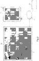
- Figure 1 is a schematic drawing depicting a medical sensing system 100 including a medical personnel display 122 and a patient display 101 according to one embodiment of the present disclosure.
- medical sensing system 100 provides for coherent integration and consolidation of multiple forms of acquisition and processing elements designed to be sensitive to a variety of methods used to acquire and interpret human biological physiology and morphological information.
- the patient display 101 is a touch-enabled, integrated computing device for the interpretation and display of medical sensing data.
- the patient display 101 is configured to present medical data at an appropriate technical level for patients and/or the patient's caretakers and/or family members.
- the patient display 101 is operable to provide diagnostic visualizations and patient image data via graphical user interfaces (GUIs) corresponding to a plurality of medical sensing modalities.
- GUIs graphical user interfaces
- the patient display 101 may be used in conjucntion with diagnostic procedures to reduce the number of visits that the patient must make to a medical facility.
- a patient 106 may have a caretaker or family member present during a diagnostic procedure, such as an angiogram.
- a clinician 107 may take the patient display 101 to the waiting caretaker and display this diagnostic data.
- the caretaker and clinician 107 can discuss treatment options and/or further diagnostic procedures and agree on the most appropriate next steps, whether that be further diagnostic procedure(s) or treatment(s).
- the treatment options display on the patient display 101 may be based on the patient's particular medical information obtained during the diagnostic procedure(s).
- the clinician 107 may then return to the patient 106 for continued diagnosis and/or treatment without requiring the patient 106 to leave.
- the patient display 101 may allow a caretaker to monitor the progress of a clinician 107 during a procedure.
- a processing system associated with the performance of the diagnostic and/or treatment plan is in communication with the patient display 101 and automically sends status updates based on the status of the ongoing diagnostic and/or treatment plan.
- the medical personnel display 122 has some similarities to the patient display 101.
- the medical personnel display 122 is also an integrated computing device capable to interpreting and displaying medical sensing data, but it may be additionally capable of acquiring and controlling medical sensing data.
- the medical personnel display is a tablet-style touch-sensitive computer.
- the medical personnel display 122 is operable to diagnostic visualizations and patient image data via graphical user interfaces (GUIs) corresponding to a plurality of medical sensing modalities. Among these options is the ability of the patient display magnified images of trouble spots and provide greater levels of detail to a sure.
- GUIs graphical user interfaces
- the medical personnel display 122 and patient display 101 will be described in greater detail in association with Figures 3-7 .
- the medical sensing system 100 is deployed in a catheter lab 104.
- the catheter lab 104 may be used to perform on a patient 106 any number of medical sensing procedures alone or in combination such as, by way of example and not limitation, angiography, intravascular ultrasound (IVUS), virtual histology (VH), forward looking IVUS (FL-IVUS), intravascular photoacoustic (IVPA) imaging, pressure, fractional flow reserve (FFR) determination, flow velocity, flow volume, coronary flow reserve (CFR) determination, optical coherence tomography (OCT), computed tomography, intracardiac echocardiography (ICE), forward-looking ICE (FLICE), intravascular palpography, transesophageal ultrasound, or any other medical sensing modalities known in the art.
- IVUS intravascular ultrasound
- VH virtual histology
- FL-IVUS forward looking IVUS
- IVPA intravascular photoacoustic
- FFR fractional flow reserve
- CFR coronary flow reserve
- OCT optical coherence tomography
- Catheter lab 104 can also conduct medical sensing procedures associated with Instant Wave-Free RatioTM Functionality (iFR® Functionality) (both trademarks of Volcano Corp.) and those disclosed in U.S. Patent Application No. 13/460,296 , entitled “DEVICES, SYSTEMS, AND METHODS FOR ASSESSING A VESSEL,” hereby incorporated by reference in its entirety, which discloses the use of pressure ratios that are available without application of a hyperemic agent. Further, medical sensing procedures associated with compensated Pd/Pa ratios suitable for estimating iFR®, FFR, and/or other accepted diagnostic pressure ratios as disclosed in U.S. Provisional Patent Application No.
- iFR® Functionality both trademarks of Volcano Corp.
- the catheter lab 104 further includes a sterile field 105 that encompasses the portions of the catheter lab surrounding the patient 106 on a procedure table 109 and a clinician 107, who may perform any number of medical sensing procedures or treatments.
- the medical personnel display 122 may be positioned within the sterile field 105 and may be utilized by the clinician 107 to control a workflow of a medical sensing procedure or treatment being performed on the patient 106.
- the clinician 107 may initiate the procedure workflow, watch real-time medical sensing data, such as pressure measurements (e.g., visual representations of pressure data, such as pressure waveforms), obtained during the procedure, and interact with the obtained medical sensing data using the medical personnel display 122 inside of the sterile field 105.
- the medical personnel display 122 may be used in conjunction with other imaging tools such as a secondary display 102 and patient display 101.
- the secondary display 102, patient display 101, and medical personnel display 122 may display the same imagery, or the medical personnel display 122 may provide alternative imagery to assist clinician 107 in diagnosing a patient or performing surgery.
- the secondary display 102 is used within the catheter lab 104. Additionally, the secondary display 102 may only be used for complicated cases where clinicians 107 may want to see additional details on a procedure.
- the medical personnel display 122 may show data that is more complicated than the patient display 101.
- a secondary display 102 may provide an alternative view angle or may overlay a highlighted image on that shown on the medical personnel display 122.
- the secondary display 102 may be used to provide additional details on specific areas of interest.
- the clinician 107 may view general diagnostic imagery on the medical personnel display 122 and select a smaller portion of the imagery to display on the secondary display 102 or patient display 101.
- the magnification of the displays 101, 102, 122 may be variable, allowing the clinician 107 to zoom in on particular areas while still keeping the general imagery in view on the medical personnel display 122.
- the clinician 107 may zoom, rotate, and otherwise manipulate such images on the displays 101, 102, 122 using simultaneous touch inputs (i.e. multitouch) and gestures.
- the secondary display 102 may be utilized outside of the sterile field 105, for instance, in other locations within the catheter lab 104 or in a control room adjacent to the catheter lab 104.
- the medical sensing system 100 additionally includes a number of interconnected medical sensing-related tools in the catheter lab 104 to facilitate a pressure-sensing workflow procedure, such as a medical sensing device 108 and a medical sensing device 110, and a processing system 124.
- the medical sensing devices 108 and 110 can include pressure monitoring elements.
- Some embodiments of the medical sensing system 100 can include an patient interface module (PIM) 112 communicatively coupled to the patient display 101, medical sensing device 108, PIM 114 communicatively coupled to the medical sensing device 110, an electrocardiogram (ECG) device 116, an angiogram system 117, and a medical personnel display 122.
- PIM patient interface module
- ECG electrocardiogram
- the secondary display 102, PIMs 112 and 114, ECG device 116, angiography system 117, and medical personnel display 122 are communicatively coupled to the processing system 124.
- the medical sensing devices 108 and 110 can include imaging elements to facilitate an imaging workflow.
- the processing system 124 is a computer workstation with the hardware and software to acquire, process, and display medical sensing data, but in other embodiments, the processing system may be any other type of computing system operable to process medical sensing data.
- the processing system 124 is operable to accept raw pressure data from the medical sensing devices 108 and 110 and/or the PIMs 112 and 114, transform the pressure data into screen displays including, e.g., visual representations such as pressure waveforms, numerical values, computed values, etc., and make the screen display available to the medical personnel display 122, so that they may be displayed to the clinician 107 for analysis.
- screen displays including, e.g., visual representations such as pressure waveforms, numerical values, computed values, etc.
- the processing system 124 includes at least a processor such as a microinterface or a dedicated central processing unit (CPU), a non-transitory computer-readable storage medium such as a hard drive, random access memory (RAM), and/or compact disk read only memory (CD-ROM), a video interface such as a graphics processing unit (GPU), and a network communication device such as an Ethernet interface.
- a processor such as a microinterface or a dedicated central processing unit (CPU), a non-transitory computer-readable storage medium such as a hard drive, random access memory (RAM), and/or compact disk read only memory (CD-ROM), a video interface such as a graphics processing unit (GPU), and a network communication device such as an Ethernet interface.
- a processor such as a microinterface or a dedicated central processing unit (CPU), a non-transitory computer-readable storage medium such as a hard drive, random access memory (RAM), and/or compact disk read only memory (CD-ROM), a video interface such as a graphics processing unit
- the processing system 124 is communicatively coupled to a data network 125.
- the data network 125 is a TCP/IP-based local area network (LAN); however in other embodiments, it may utilize a different protocol such as Synchronous Optical Networking (SONET), or may be a wide area network (WAN).
- SONET Synchronous Optical Networking
- the network 125 may utilize wired and/or wireless connections. In some instances, at least a portion of the network 125 is a cellular network.
- Other components of the system 100 such as the secondary display 102 and the medical personnel display 122, are connected to the processing system 124 either directly through a wired or wireless interface, or indirectly via network 125 or other networking components.
- the processing system 124 may connect to various resources via the network 125, such as a Digital Imaging and Communications in Medicine (DICOM) system, a Picture Archiving and Communication System (PACS), and a Hospital Information System.
- the processing system 124 can be similar to a multi-modality processing system that processes medical sensing data disclosed in U.S. Patent No. 8,754,865 , entitled “MEDICAL MEASURING SYSTEM AND METHOD” and issued on June 17, 2014, and U.S. Patent Application No. 61/473,570 , entitled “MULTI-MODALITY MEDICAL SENSING SYSTEM AND METHOD” and filed on April 8, 2011.
- the PIM 112 and PIM 114 are operable to respectively receive medical sensing data collected from the patient 106 by the medical sensing device 108 and medical sensing device 110 and are operable to transmit the received data to the processing system 124.
- the PIM 112 and PIM 114 transmit the medical sensing data over a Peripheral Component Interconnect Express (PCIe) data bus connection, but, in other embodiments, they may transmit data over a USB connection, a Thunderbolt connection, a FireWire connection, or some other high-speed data bus connection.
- the ECG device 116 is operable to transmit electrocardiogram signals or other hemodynamic data from patient 106 to the processing system 124.
- the medical personnel display 122 is operable to display the ECG data alongside medical sensing data.
- the processing system 124 may be operable to synchronize data collection with the catheters 108 and 110 using ECG signals from the ECG 116.
- the angiogram system 117 is operable to collect x-ray, computed tomography (CT), or magnetic resonance images (MRI) of the patient 106 and transmit them to the processing system 124.
- CT computed tomography
- MRI magnetic resonance images
- the processing system 124 may co-register image data from angiogram system 117 (e.g. x-ray data, MRI data, CT data, etc.) with sensing data from the catheters 108 and 110.
- the co-registration may be performed to generate three-dimensional images with the sensing data.
- Such co-registered 3-D images data may be viewable on the medical personnel display 122.
- a clinician may rotate, zoom, and otherwise manipulate such 3-D images on the medical personnel display 122 using simultaneous touch inputs (i.e. multitouch) and gestures.
- medical sensing tools in system 100 are communicatively coupled to the processing system 124 via a wired connection such as a standard copper link or a fiber optic link.
- medical personnel display 122 and patient display 101 may be communicatively and/or electrically coupled to the processing system 124 via a Universal Serial Bus (USB) connection, a Power-over-Ethernet connection, a Thunderbolt connection, a FireWire connection, or some other high-speed data bus connection.
- USB Universal Serial Bus
- the patient display 101 may communicate with the processing system through a network, which can include wired and/or wireless communications.
- the patient display 101 may be transported outside the catheter lab 104 to provide caretakers or family of the patient 106 with medical information on the procedure.
- the patient display 101 may assist a clinician 107 in explaining diagnostic information and treatment options in a variety of ways.
- the clinician 107 may display medical images on the patient display 101 that will give context to the caretaker or family member, such anatomical drawings, images from other patients, or diagnostic images from the current patient 106.
- the clinician 107 may display simulations of treatment options on the patient display 101 such as the likely results of a procedure as compared to the current diagnostic images of the patient 106.
- the display of medical information on the patient display 106 may be simplified to help the patient 106 or caretaker better understand the treatment plan.
- Simplification methods include converting numeric data into maps or graphs, eliminating extraneous information or imagery, magnifying images to focus on areas of importance, and/or using color-coded images.
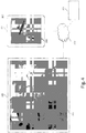
- FIG. 2 is a schematic drawing depicting a medical sensing system 200 including a wireless patient display 101, wireless medical personnel display 122, and wireless secondary display 202 according to another embodiment of the present disclosure.
- the medical sensing system 200 is similar to the system 100 of Figure 1 but the medical sensing tools including the wireless medical personnel display 122, a wireless PIM 204, and a wireless PIM 206 communicate with a wireless network 208 via wireless networking protocols.
- the medical personnel display 122 may send and receive workflow control parameters, medical sensing images, and measurement data to and from a remote processing system via IEEE 802.11 Wi-Fi standards, Ultra Wide-Band (UWB) standards, wireless FireWire, wireless USB, Bluetooth, or another high-speed wireless networking standard.
- IEEE 802.11 Wi-Fi standards Ultra Wide-Band (UWB) standards
- wireless FireWire wireless USB
- Bluetooth or another high-speed wireless networking standard.
- wireless capability allows the clinician 107 to more freely position the medical personnel display 122 inside or outside of the sterile field 105 for better workflow management.
- the patient display 101 includes an integrally formed housing 302 that is easy to grasp and move around a catheter lab or other medical setting.
- the integrally formed housing 302 may be seamlessly molded from materials such as thermoplastic or thermosetting plastic or moldable metal.
- the integrally formed housing 302 may comprise a plurality of housing portions fixedly bonded in a substantially permanent manner to form an integral housing.
- the housing 302 is resistant to fluids, and, in one embodiment, may have a rating of IPX4 against fluid ingress as defined by the International Electrotechnical Commission (IEC) standard 60529.
- the hub may have a different fluid ingress rating.
- the housing 302 has a width, height, or thickness that is conducive to portability.
- the patient display 101 is configured to be used in conjunction with the medical personnel display 122.
- the patient display 101 and medical personnel display 122 receive data obtained by intravascular sensors and/or imaging components and display corresponding medical imagery 301.
- Such imagery 301 can include static images, video, 3-D renderings, raw sensor or imaging data, filtered sensor or imaging data, calculated sensor or imaging data, and/or other data representative of the patient's anatomy.
- This data may be collected during a diagnostic procedure or may be collected during a surgical procedure, such as PCI.
- diagnostic visualizations are overlaid on images of a vessel displayed on the medical personnel display 122 and/or patient display 101. These diagnostic visualizations may assist the clinician 107 in determining the best available treatment options for a particular patient 106.
- the diagnostic visualizations can include markings, colors, numerical values, or other representations of the data obtained from medical instruments, such as guidewires and catheters.
- the diagnostic visualizations can include intensity maps based on recorded pressure measurements and may incorporate graphs of corresponding pressure ratios.
- the diagnostic visualizations may be overlaid onto extravascular images such as two-dimensional angiographic images, three-dimensional angiographic images, and computed tomography angiographic (CTA) images, and intravascular images such as ultrasound (IVUS) images and optical coherence tomography (OCT) images.
- the diagnostic visualizations can include one type of image overlaid onto another type of image.
- one or more treatment options can be simulated and the diagnostic visualizations updated based on the parameters associated with each particular simulated treatment option. In this manner, an estimated result or outcome for each treatment option can be visually provided to the clinician.
- the diagnostic visualizations and/or simulated treatments can be carried out as described in one or more of PCT Patent Application Publication No. WO 2013/028612, filed August 20, 2012 and titled “DEVICES, SYSTEMS, AND METHODS FOR VISUALLY DEPICTING A VESSEL AND EVALUATING TREATMENT OPTIONS," U.S. Provisional Patent Application No. 61/895,909, filed October 25, 2013 and titled “Devices, Systems, and Methods for Vessel Assessment," U.S. Provisional Patent Application No.
- a clinician 107 can determine the best treatment option for the patient.
- Medical supervisors may also use the medical personnel display 122 to check the work of clinicians 107 or to offer second opinions to a patient 106.
- the images, diagnostic visualizations, or simulated treatments displayed on the medical personnel display may also be displayed on the patient display 101.
- These visualizations may sent directly from the medical personnel display 122 to the patient display 101 via network 207, or visualizations may be sent to both the medical personnel display 122 and patient display 101 from the processing system. Additionally, simplified versions of these visualizations may be available on the patient display 101 to aid in patient 106 understanding.
- This simplification may involve displaying only a portion 303 of the overall imagery 301 on the patient display 101 to show only areas of interest.
- the patient display 101 may be equipped with a touch screen interface, allowing a clinician 107 or patient 106 to easily manipulate imagery 301 using simultaneous touch inputs and gestures.
- the patient display 101 may be configured to be able to zoom into areas of interest and display images, graphical information, and text relating to the imagery 301.
- Figure 3 shows a zoomed in portion 303 of the general imagery 301 that is displayed on the patient display 101.
- a communication network 208 connects the medical personnel display 122 and the patient display 101 to the processing system 124.
- a wireless connection to the patient display 101 may be favored during diagnostic procedures to allow a clinician 107 or caretaker to continual monitor certain key aspects of the procedure, and may allow a clinician 107 to communicate diagnostic information and treatment options with a patient 106, another clinician 107, and/or a caretaker or family member of the patient.
- the patient display 101 may also be used to display additional diagnostic information for the portion 303 corresponding to the region of interest of the vessel.
- the medical personnel display 122 displays imagery 301 of a patient while the patient display 101 shows the portion 303 of interest with diagnostic visualizations overlaid.
- pressure ratios such as FFR or iFR values, are shown along the region of interest of the vessel. As shown, there is a significant drop in the pressure ratio from 0.92 to 0.68 that can be indicative of a severe blockage or lesion. It is understood that any of a number of other types of diagnostic visualizations may be utilized as described above.
- one or more treatment options can be simulated and the diagnostic visualizations displayed on the patient display 101 can be updated based on the parameters associated with a particular simulated treatment option.
- Figure 4 shows an example of this approach.
- Figure 4 shows the simulated deployment of a stent 306 and the corresponding resulting change in the diagnostic visualizations.
- the severe drop to 0.68 shown Figure 3 is estimated to be improved significantly by deployment of the stent to a value of 0.91.
- estimated results or outcomes for each treatment option can be visually provided to the clinician 107 on the medical personnel display 122 and to the patient 106 or caretaker on the patient display 101.
- a simulated procedure may be displayed on the patient display 101 to show the likely outcome of a procedure.
- a simulated stent 306 is shown on the patient display 101 as well as statistical data 303 on the size and position of the stent.
- a clinician 107 may also place markers 305 on the imagery 301 of the patient display 101 to indicate important areas or provide ongoing pressure measurements. Simulations such as those shown in Figure 4 may afford a clinician 107 or patient 106 a view of both the predicted result of a procedure and real-time imagery 301, affording a detailed and readily understandable analysis of treatment options. This analysis is also easily shared with a patient 106 or a patient's guardian or caretaker via the patient display 101.
- Figure 5 shows a patient display 101 in which general imagery 301 is shown in as simplified manner. Numerical values and other text has been removed from the imagery 301, and the simulated stent 401 is shown in a simplified manner.
- the patient display and medical personnel display may be configured to interact.
- the displays of both devices 101, 122 may be linked so that the clinician 107 and the patient 106 or caretaker can view the same images.
- a clinician 107 operating the medical personnel display 122 may be able to highlight portions of interest on the patient display 101, or may be able to change the view of both devices 101, 122 according to the desire of the patient 106 or caretaker. Simulations may be displayed on both devices 101, 122 allowing the parties to discuss the risks and benefits of possible PCI procedures.
- FIG. 6 shows a functional block diagram of the patient display 101 according to aspects of the present disclosure.
- the touch-sensitive display 307 that comprises both a touch panel 308 and a flat panel display 309.
- the touch panel 308 overlays the flat panel display 308 and accepts user input via human touch, stylus touch, or some other analogous input method.
- the touch-sensitive display 307 displays images and accepts user input on the same surface.
- the touch panel 308 is a resistive-type panel, but in alternative embodiments it may be a capacitive-type panel, projective-type panel, or some other suitable type of touch enabled input panel.
- the touch panel 308 is operable to accept multiple inputs simultaneously (multitouch), for instance, to enable rotation of a three-dimensional rendering of a vessel along multiple axes. Additionally, the touch panel 308 is capable of receiving input when a sterile drape 301 is covering the patient display 101 and also when a user is gloved.
- the touch panel 308 is controlled by a touch interface 310 disposed within the housing 302. Further, when a clinician makes contact with the touch panel 308, the touch panel is operable to provide haptic feedback via a haptics interface 312 and haptics drivers 314. This haptic technology is operable to simulate a plurality of sensations on the touch panel 308 by varying the intensity and frequency of vibrations generated when a user contacts the touch panel.
- the housing 302 may include a sheath configured to store a stylus therein.
- a clinician may remove the stylus from the sheath in the housing to make measurements on the medical personnel display 122 and store it when the measurements have been completed.
- the flat panel display 309 Beneath the touch panel 308 is the flat panel display 309 that presents a graphical user interface (GUI) 316 to a user.
- GUI graphical user interface
- the flat panel display 309 is a LCD display but in alternative embodiments, it may be a different type of display such an LED display or an AMOLED display.
- the flat panel display 309 is illuminated by a LED backlight power inverter 318.
- the GUI 316 not only allows a clinician to control a medical sensing workflow, but also view and interact with pressure data obtained from a patient in the sterile field.
- the patient display 101 includes a single board processing platform 320 within the housing 302 that is operable to render the GUI 316 and process user touch input.
- the processing platform has a pico form factor and includes integrated processing components such as a processor 321, system memory 322, graphics processing unit (GPU), communications module 323, and I/O bus interface.
- the processor 321 may be a low power processor such as an Intel Atom® processor or an ARM-based processor
- the communications module 323 may be a 10/100/1Gb Ethernet module.
- the I/O bus interface may be a Universal Serial Bus (USB) interface.
- the patient display 101 further includes a storage module 324 that is a non-transitory computer readable storage medium operable to store an operating system (i.e.
- the processor 321 is configured to execute software and instructions stored on the storage module 324.
- the storage module 324 is a solid state drive (SSD) hard drive communicatively coupled to the processing platform 320 via a SATA connection, but, in alternative embodiments, it may be any other type of non-volatile or temporary storage module.
- the patient display 101 further includes a wireless communications module 326 communicatively coupled to the processing platform 320.
- the wireless communications module is an IEEE 802.11 Wi-Fi module, but in other may be an Ultra Wide-Band (UWB) wireless module, a wireless FireWire module, a wireless USB module, a Bluetooth module, or another high-speed wireless networking module.
- UWB Ultra Wide-Band
- the patient display 101 is powered via both a wired 12VDC power-over-Ethernet (PoE) connection 328 and a battery 330 disposed within the housing 302.
- the battery 330 may be sealed within the integrally formed housing 302 and may be recharged through electrical contacts disposed on the exterior of the housing and electrically coupled to the battery.
- the front wall 350 may include one or more electrical contacts 358 through which the battery 330 may be charged when the interface is mounted to objects with compatible charging structure.
- the housing 302 may include a battery compartment with a removable cover to permit battery replacement. Such a battery compartment cover may be resistant to fluid ingress (e.g., with an IPX4 rating).
- the beside interface 300 may be coupled to a processing system in the catheter lab via the PoE connection 328, over which it receives medical sensing images that have been captured from the patient and rendered on the processing system.
- a processing system in the catheter lab via the PoE connection 328, over which it receives medical sensing images that have been captured from the patient and rendered on the processing system.
- the patient display 101 when the patient display 101 is coupled to the PoE connection 328, it receives power and communications over the same physical wire.
- the patient display 101 is disconnected from the PoE connection 328, it runs on battery power and receives data wirelessly via the wireless communications module 326.
- the beside interface may directly communicate with a processing system (i.e. in an ad-hoc wireless mode), or, alternatively, it may communicate with a wireless network that serves a plurality of wireless devices.
- the patient display 101 may receive power and data through different wired connections, or receive data communications through a wired data connection and power from the battery 330, or receive data communications through the wireless module 326 and power from a wired electrical connection.
- the patient display 101 may be used in a semi-wireless configuration, in which the battery 330 provides backup power to the interface when the interface is temporarily disconnected from a wired power source. For example, if at the beginning of a procedure, the patient display 101 is connected to a PoE connection (or other type of wired connection) and during the procedure the interface must be disconnected from the PoE connection to allow for a cabling adjustment, the battery 330 may keep the interface alive until a PoE connection can be re-established. In this manner, a full power-off and reboot of the interface 300 is avoided during a procedure.
- a DC-DC power converter 332 converts input voltage to a voltage usable by the processing platform 320.
- the patient display 101 includes specific components described herein, the patient display 101 may include any number of additional components, for example a charge regulator interposed between the electrical contacts and the battery, and may be configured in any number of alternative arrangements in alternative embodiments.
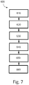
- Figure 7 is a flowchart illustrating a method 600 of planning the treatment of a patient.
- the method 600 will be described in the context of a pressure-sensing procedure, such as an iFR procedure, but may equally apply to any number of medical sensing or treatment procedures, such as an FFR procedure, an IVUS procedure, OCT procedure, a FLIVUS procedure, an ICE procedure, etc.
- the method 600 can be better understood with reference to the Figures 8-11 .
- FIG. 8 shown therein is a vessel 800 having a stenosis according to an embodiment of the present disclosure.
- Figure 8 is a diagrammatic perspective view of the vessel 800
- Figure 9 is a partial cross-sectional perspective view of a portion of the vessel 800.
- the vessel 800 includes a proximal portion 802 and a distal portion 804.
- a lumen 806 extends along the length of the vessel 800 between the proximal portion 802 and the distal portion 804.
- the lumen 806 is configured to allow the flow of fluid through the vessel.
- the vessel 800 is a blood vessel.
- the vessel 800 is a coronary artery.
- the lumen 806 is configured to facilitate the flow of blood through the vessel 800.
- the vessel 800 includes a stenosis 808 between the proximal portion 802 and the distal portion 804.
- Stenosis 808 is generally representative of any blockage or other structural arrangement that results in a restriction to the flow of fluid through the lumen 806 of the vessel 800.
- Embodiments of the present disclosure are suitable for use in a wide variety of vascular applications, including without limitation coronary, peripheral (including but not limited to lower limb, carotid, and neurovascular), renal, and/or venous.
- the stenosis 808 may be a result of plaque buildup, including without limitation plaque components such as fibrous, fibro-lipidic (fibro fatty), necrotic core, calcified (dense calcium), blood, fresh thrombus, and mature thrombus.
- plaque components such as fibrous, fibro-lipidic (fibro fatty), necrotic core, calcified (dense calcium), blood, fresh thrombus, and mature thrombus.
- the composition of the stenosis will depend on the type of vessel being evaluated. In that regard, it is understood that the concepts of the present disclosure are applicable to virtually any type of blockage or other narrowing of a vessel that results in decreased fluid flow.
- the lumen 806 of the vessel 800 has a diameter 810 proximal of the stenosis 808 and a diameter 812 distal of the stenosis.
- the diameters 810 and 812 are substantially equal to one another.
- the diameters 810 and 812 are intended to represent healthy portions, or at least healthier portions, of the lumen 806 in comparison to stenosis 808. Accordingly, these healthier portions of the lumen 806 are illustrated as having a substantially constant cylindrical profile and, as a result, the height or width of the lumen has been referred to as a diameter.
- the diameters 810 and 812 are understood to be representative of a relative size or cross-sectional area of the lumen and do not imply a circular cross-sectional profile.
- stenosis 808 includes plaque buildup 814 that narrows the lumen 806 of the vessel 800.
- the plaque buildup 814 does not have a uniform or symmetrical profile, making angiographic evaluation of such a stenosis unreliable.
- the plaque buildup 814 includes an upper portion 816 and an opposing lower portion 818.
- the lower portion 818 has an increased thickness relative to the upper portion 816 that results in a non-symmetrical and non-uniform profile relative to the portions of the lumen proximal and distal of the stenosis 808.
- the plaque buildup 814 decreases the available space for fluid to flow through the lumen 806.
- the cross-sectional area of the lumen 806 is decreased by the plaque buildup 814.
- the lumen 806 has a height 820, which is representative of a reduced size or cross-sectional area relative to the diameters 810 and 812 proximal and distal of the stenosis 808.
- the stenosis 808, including plaque buildup 814 is exemplary in nature and should be considered limiting in any way. In that regard, it is understood that the stenosis 808 has other shapes and/or compositions that limit the flow of fluid through the lumen 806 in other instances.
- instruments 830 and 832 may be any form of device, instrument, or probe sized and shaped to be positioned within a vessel.
- the instruments 830 and 832 can be implemented in the medical sensing system 100 ( Figure 1 ) as medical sensing devices 108 and 110.
- instrument 830 is generally representative of a guide wire
- instrument 832 is generally representative of a catheter.
- instrument 830 extends through a central lumen of instrument 832.
- the instruments 830 and 832 take other forms.
- the instruments 830 and 832 are of similar form in some embodiments.
- both instruments 830 and 832 are guide wires. In other instances, both instruments 830 and 832 are catheters. On the other hand, the instruments 830 and 832 are of different form in some embodiments, such as the illustrated embodiment, where one of the instruments is a catheter and the other is a guide wire. Further, in some instances, the instruments 830 and 832 are disposed coaxial with one another, as shown in the illustrated embodiment of Figure 10 . In other instances, one of the instruments extends through an off-center lumen of the other instrument. In yet other instances, the instruments 830 and 832 extend side-by-side. In some particular embodiments, at least one of the instruments is as a rapid-exchange device, such as a rapid-exchange catheter.
- the other instrument is a buddy wire or other device configured to facilitate the introduction and removal of the rapid-exchange device.
- the single instrument incorporates aspects of the functionalities (e.g., data acquisition) of both instruments 830 and 832.
- Instrument 830 is configured to obtain diagnostic information about the vessel 800.
- the instrument 830 includes one or more sensors, transducers, and/or other monitoring elements configured to obtain the diagnostic information about the vessel.
- the diagnostic information includes one or more of pressure, flow (velocity and/or volume), images (including images obtained using ultrasound (e.g., IVUS), OCT, thermal, and/or other imaging techniques), temperature, and/or combinations thereof.
- the one or more sensors, transducers, and/or other monitoring elements are positioned adjacent a distal portion of the instrument 830 in some instances.
- the one or more sensors, transducers, and/or other monitoring elements are positioned less than 30 cm, less than 10 cm, less than 5 cm, less than 3 cm, less than 2 cm, and/or less than 1 cm from a distal tip 834 of the instrument 830 in some instances. In some instances, at least one of the one or more sensors, transducers, and/or other monitoring elements is positioned at the distal tip of the instrument 830.
- the instrument 830 includes at least one element configured to monitor pressure within the vessel 800.
- the pressure monitoring element can take the form a piezo-resistive pressure sensor, a piezo-electric pressure sensor, a capacitive pressure sensor, an electromagnetic pressure sensor, a fluid column (the fluid column being in communication with a fluid column sensor that is separate from the instrument and/or positioned at a portion of the instrument proximal of the fluid column), an optical pressure sensor, and/or combinations thereof.
- one or more features of the pressure monitoring element are implemented as a solid-state component manufactured using semiconductor and/or other suitable manufacturing techniques.
- the instrument 830 is sized such that it can be positioned through the stenosis 808 without significantly impacting fluid flow across the stenosis, which would impact the distal pressure reading. Accordingly, in some instances the instrument 830 has an outer diameter of 0.018" or less. In some embodiments, the instrument 830 has an outer diameter of 0.014" or less.
- Instrument 832 is also configured to obtain diagnostic information about the vessel 100. In some instances, instrument 832 is configured to obtain the same diagnostic information as instrument 830. In other instances, instrument 832 is configured to obtain different diagnostic information than instrument 830, which may include additional diagnostic information, less diagnostic information, and/or alternative diagnostic information.
- the diagnostic information obtained by instrument 832 includes one or more of pressure, flow (velocity and/or volume), images (including images obtained using ultrasound (e.g., IVUS), OCT, thermal, and/or other imaging techniques), temperature, and/or combinations thereof. Instrument 832 includes one or more sensors, transducers, and/or other monitoring elements configured to obtain this diagnostic information.
- the one or more sensors, transducers, and/or other monitoring elements are positioned adjacent a distal portion of the instrument 832 in some instances. In that regard, the one or more sensors, transducers, and/or other monitoring elements are positioned less than 30 cm, less than 10 cm, less than 5 cm, less than 3 cm, less than 2 cm, and/or less than 1 cm from a distal tip 836 of the instrument 832 in some instances. In some instances, at least one of the one or more sensors, transducers, and/or other monitoring elements is positioned at the distal tip of the instrument 832.
- instrument 832 also includes at least one element configured to monitor pressure within the vessel 800.
- the pressure monitoring element can take the form a piezo-resistive pressure sensor, a piezo-electric pressure sensor, a capacitive pressure sensor, an electromagnetic pressure sensor, a fluid column (the fluid column being in communication with a fluid column sensor that is separate from the instrument and/or positioned at a portion of the instrument proximal of the fluid column), an optical pressure sensor, and/or combinations thereof.
- one or more features of the pressure monitoring element are implemented as a solid-state component manufactured using semiconductor and/or other suitable manufacturing techniques.
- Siemens AXIOM Sensis, Mennen Horizon XVu, and Philips Xper IM Physiomonitoring 5 can be utilized for instrument 832 in some instances.
- At least one of the instruments 830 and 832 is configured to monitor a pressure within the vessel 800 distal of the stenosis 808 and at least one of the instruments 830 and 832 is configured to monitor a pressure within the vessel proximal of the stenosis.
- the instruments 830, 832 are sized and shaped to allow positioning of the at least one element configured to monitor pressure within the vessel 800 to be positioned proximal and/or distal of the stenosis 808 as necessary based on the configuration of the devices.
- Figure 10 illustrates a position 838 suitable for measuring pressure distal of the stenosis 808.
- the position 838 is less than 5 cm, less than 3 cm, less than 2 cm, less than 1 cm, less than 5 mm, and/or less than 2.5 mm from the distal end of the stenosis 808 (as shown in Figure 8 ) in some instances.
- Figure 10 also illustrates a plurality of suitable positions for measuring pressure proximal of the stenosis 808.
- positions 840, 842, 844, 846, and 848 each represent a position that is suitable for monitoring the pressure proximal of the stenosis in some instances.
- the positions 840, 842, 844, 846, and 848 are positioned at varying distances from the proximal end of the stenosis 808 ranging from more than 20 cm down to about 5 mm or less.
- the proximal pressure measurement will be spaced from the proximal end of the stenosis. Accordingly, in some instances, the proximal pressure measurement is taken at a distance equal to or greater than an inner diameter of the lumen of the vessel from the proximal end of the stenosis.
- the proximal pressure measurement is generally taken at a position proximal of the stenosis and distal of the aorta, within a proximal portion of the vessel.
- the proximal pressure measurement is taken from a location inside the aorta. In other instances, the proximal pressure measurement is taken at the root or ostium of the coronary artery.
- At least one of the instruments 830 and 832 is configured to monitor pressure within the vessel 800 while being moved through the lumen 806.
- instrument 830 is configured to be moved through the lumen 806 and across the stenosis 808.
- the instrument 830 is positioned distal of the stenosis 808 and moved proximally (i.e., pulled back) across the stenosis to a position proximal of the stenosis in some instances.
- the instrument 830 is positioned proximal of the stenosis 808 and moved distally across the stenosis to a position distal of the stenosis.
- Movement of the instrument 830, either proximally or distally is controlled manually by medical personnel (e.g., hand of a surgeon) in some embodiments.
- movement of the instrument 830, either proximally or distally is controlled automatically by a movement control device (e.g., a pullback device, such as the Trak Back® II Device available from Volcano Corporation).
- the movement control device controls the movement of the instrument 830 at a selectable and known speed (e.g., 2.0 mm/s, 1.0 mm/s, 0.5 mm/s, 0.2 mm/s, etc.) in some instances. Movement of the instrument 830 through the vessel is continuous for each pullback or push through, in some instances.
- the instrument 830 is moved step-wise through the vessel (i.e., repeatedly moved a fixed amount of distance and/or a fixed amount of time).
- Some aspects of the visual depictions discussed below are particularly suited for embodiments where at least one of the instruments 830 and 832 is moved through the lumen 806. Further, in some particular instances, aspects of the visual depictions discussed below are particularly suited for embodiments where a single instrument is moved through the lumen 806, with or without the presence of a second instrument.
- a single instrument has a benefit in that it avoids issues associated with variations in pressure measurements of one instrument relative to another over time, which is commonly referred to as drift.
- drift a major source of drift in traditional Fractional Flow Reserve (FFR) measurements is divergence in the pressure reading of a guide wire relative to the pressure reading of a guide catheter.
- FFR Fractional Flow Reserve
- this divergence has an impact on the resulting FFR value.
- drift is negligible or non-existent.
- the single instrument is utilized to obtain relative changes in pressures as it is moved through the vessel such that the time period between pressure measurements is short enough to prevent any impact from any changes in pressure sensitivity of the instrument (e.g., less than 500 ms, less than 100 ms, less than 50 ms, less than 10 ms, less than 5 ms, less than 1 ms, or otherwise).
- the time period between pressure measurements is short enough to prevent any impact from any changes in pressure sensitivity of the instrument (e.g., less than 500 ms, less than 100 ms, less than 50 ms, less than 10 ms, less than 5 ms, less than 1 ms, or otherwise).
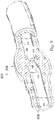
- Figure 11 is a diagrammatic, schematic view of the system 850.
- the system 850 can be implemented as the medical sensing system 100 ( Figure 1 ).
- one or more components of the medical sensing system 100 can be additionally implemented in the system 850, such as a patient display 101 having a touch-sensitive display.
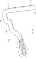
- the system 850 includes an instrument 852.
- instrument 852 is suitable for use as at least one of instruments 830 and 832 ( Figs. 9-11 ) and/or medical sensing devices 108 and 110 ( Figure 1 ), discussed above.
- the instrument 852 includes features similar to those discussed above with respect to instruments 830 and 832 in some instances.
- the instrument 852 is a guide wire having a distal portion 854 and a housing 856 positioned adjacent the distal portion.
- the housing 856 is spaced approximately 3 cm from a distal tip of the instrument 852.
- the housing 856 is configured to house one or more sensors, transducers, and/or other monitoring elements configured to obtain the diagnostic information about the vessel.
- the housing 856 contains at least a pressure sensor configured to monitor a pressure within a lumen in which the instrument 852 is positioned.
- a shaft 858 extends proximally from the housing 856.
- a torque device 860 is positioned over and coupled to a proximal portion of the shaft 858.
- a proximal end portion 862 of the instrument 852 is coupled to a connector 864.
- a cable 866 extends from connector 864 to a connector 868.
- connector 868 is configured to be plugged into an interface 870.
- interface 870 is a patient interface module (PIM) in some instances.
- PIM patient interface module
- the interface 870 can be implemented as the PIM 112 ( Figure 1 ).
- the cable 866 is replaced with a wireless connection.
- various communication pathways between the instrument 852 and the interface 870 may be utilized, including physical connections (including electrical, optical, and/or fluid connections), wireless connections, and/or combinations thereof.
- the interface 870 is communicatively coupled to a computing device 872 via a connection 874.
- Computing device 872 is generally representative of any device suitable for performing the processing and analysis techniques discussed within the present disclosure.
- the computing device 872 includes a processor, random access memory, and a storage medium.
- the computing device 872 is programmed to execute steps associated with the data acquisition and analysis described herein. Accordingly, it is understood that any steps related to data acquisition, data processing, instrument control, and/or other processing or control aspects of the present disclosure may be implemented by the computing device using corresponding instructions stored on or in a non-transitory computer readable medium accessible by the computing device.
- the computing device 872 is the patient display 101.
- the processing steps described herein can be performed by one or more processing components of the patient display 101, such as the processing platform 320.
- the computing device 872 is a console device.
- the computing device 872 is similar to the S5 Imaging System or the S5i Imaging System, each available from Volcano Corporation.
- the computing device 872 is portable (e.g., handheld, on a rolling cart, etc.).
- the computing device 872 comprises a plurality of computing devices.
- the different processing and/or control aspects of the present disclosure may be implemented separately or within predefined groupings using a plurality of computing devices. Any divisions and/or combinations of the processing and/or control aspects described below across multiple computing devices are within the scope of the present disclosure.
- connection 874 facilitate communication between the one or more sensors, transducers, and/or other monitoring elements of the instrument 852 and the computing device 872.
- this communication pathway is exemplary in nature and should not be considered limiting in any way.
- any communication pathway between the instrument 852 and the computing device 872 may be utilized, including physical connections (including electrical, optical, and/or fluid connections), wireless connections, and/or combinations thereof.
- the connection 874 is wireless in some instances.
- the connection 874 includes a communication link over a network (e.g., intranet, internet, telecommunications network, and/or other network).
- the computing device 872 is positioned remote from an operating area where the instrument 152 is being used in some instances. Having the connection 874 include a connection over a network can facilitate communication between the instrument 852 and the remote computing device 872 regardless of whether the computing device is in an adjacent room, an adjacent building, or in a different state/country. Further, it is understood that the communication pathway between the instrument 852 and the computing device 872 is a secure connection in some instances. Further still, it is understood that, in some instances, the data communicated over one or more portions of the communication pathway between the instrument 852 and the computing device 872 is encrypted.
- the system 850 also includes an instrument 875.
- instrument 875 is suitable for use as medical sensing devices 108 and 110 ( Figure 1 ), discussed above. Accordingly, in some instances the instrument 875 includes features similar to those discussed above with respect to instruments 108 and 110 in some instances.
- the instrument 875 is a catheter-type device.
- the instrument 875 includes one or more sensors, transducers, and/or other monitoring elements adjacent a distal portion of the instrument configured to obtain the diagnostic information about the vessel.
- the instrument 875 includes a pressure sensor configured to monitor a pressure within a lumen in which the instrument 875 is positioned.
- the instrument 875 is in communication with an interface 876 via connection 877.
- interface 876 is a hemodynamic monitoring system or other control device, such as Siemens AXIOM Sensis, Mennen Horizon XVu, and Philips Xper IM Physiomonitoring 5.
- instrument 875 is a pressure-sensing catheter that includes fluid column extending along its length.
- interface 876 includes a hemostasis valve fluidly coupled to the fluid column of the catheter, a manifold fluidly coupled to the hemostasis valve, and tubing extending between the components as necessary to fluidly couple the components.
- the fluid column of the catheter is in fluid communication with a pressure sensor via the valve, manifold, and tubing.
- the pressure sensor is part of interface 876.
- the pressure sensor is a separate component positioned between the instrument 875 and the interface 876.
- the interface 876 is communicatively coupled to the computing device 872 via a connection 878.
- interface 876 and connections 877 and 878 facilitate communication between the one or more sensors, transducers, and/or other monitoring elements of the instrument 875 and the computing device 872.
- this communication pathway is exemplary in nature and should not be considered limiting in any way.
- any communication pathway between the instrument 875 and the computing device 872 may be utilized, including physical connections (including electrical, optical, and/or fluid connections), wireless connections, and/or combinations thereof.
- the connection 878 is wireless in some instances.
- the connection 878 includes a communication link over a network (e.g., intranet, internet, telecommunications network, and/or other network).
- the computing device 872 is positioned remote from an operating area where the instrument 875 is being used in some instances. Having the connection 878 include a connection over a network can facilitate communication between the instrument 875 and the remote computing device 872 regardless of whether the computing device is in an adjacent room, an adjacent building, or in a different state/country. Further, it is understood that the communication pathway between the instrument 875 and the computing device 872 is a secure connection in some instances. Further still, it is understood that, in some instances, the data communicated over one or more portions of the communication pathway between the instrument 875 and the computing device 872 is encrypted.
- the system 850 does not include interface 870 and/or interface 876.
- the connector 868 (or other similar connector in communication with instrument 852 or instrument 875) may plug into a port associated with computing device 872.
- the instruments 852, 875 may communicate wirelessly with the computing device 872.
- the communication pathway between either or both of the instruments 852, 875 and the computing device 872 may have no intermediate nodes (i.e., a direct connection), one intermediate node between the instrument and the computing device, or a plurality of intermediate nodes between the instrument and the computing device.
- the system 850 can additionally include a patient display 101, such as the patient display 101 of medical sensing system 100 ( Figure 1 ).
- the medical personnel display 122 may be utilized by a clinician to control a instruments 852 and 875 to acquire pressure data during a procedure, watch real-time medical pressure measurements (e.g., visual representations of pressure data, such as pressure waveforms, numerical values, etc.), and interact with the obtained medical sensing data using the patient display 101.
- the patient display 101 can be communicatively coupled to the medical personnel display 122, computing device 872, the interfaces 870 and 876, and/or the instruments 864 and 875.
- the method 600 begins at block 610 where pressure measurements are obtained using diagnostic instruments such as instruments 830, 832.
- the diagnostic instruments are also configured to obtain diagnostic information about the vessel 800.
- these instruments 830, 320 are sized and shaped to allow positioning of the at least one element configured to monitor pressure within the vessel 800 to be positioned proximal and/or distal of stenosis 808 as necessary based on the configuration of the devices.
- sensors may be integrated with this instrument, such as piezo-resistive pressure sensors, piezo-electric pressure sensors, capacitive pressure sensors, electromagnetic pressure sensors, a fluid column, optical pressure sensors, and/or combinations thereof.
- diagnostic instruments are used to obtain an image of a patient's vessel.
- This image may be an extravascular image, such as a two dimensional angiographic image, a three dimensional angiographic image, and a computed tomography angiographic (CTA) image, or an intravascular image such as an intravascular ultrasound (IVUS) image or an optical coherence tomography (OCT) image.
- the image of this vessel may be created using pressure data obtained by instruments 830, 832, and may take the form of a pressure map.
- the pressure measurement data and image of the patient's vessel are transmitted to a processing system.
- This processing system may take the form a computing device 872.
- the pressure measurement and image data may be sent directly to a PIM 112 or interface 870.
- the transmission of data may be accomplished through a wired connection (using cable 866) or a wireless connection.
- the processing system may be positioned remote from an operating area where the diagnostic instrument is being used. Having the connection 874 include a connection over a network can facilitate communication between the diagnostic instrument and the processing system regardless of whether the computing device is in an adjacent room, an adjacent building, or in a different state/country.
- a processing system may collect raw pressure data from the diagnostic instrument and process the data to render visual representations of the obtained pressure data.
- data is transmitted to the medical personnel display 122 and facilitate the display of medical imagery.
- This medical imagery may be diagnostic visualizations and may include numerical, graphical, textual, and/or other suitable visualizations.
- the medical personnel display 122 retrieves the visual representations from the processing system and displays them to a user in real-time.
- an image of the vessel is displayed on the medical personnel display 122 along with diagnostic visualizations based on the pressure measurements obtained in block 610.
- a clinician 107 may study and select treatment options based on the diagnostic visualizations as discussed above, a PIM 112 or interface 870 may be used for the transmission of data.
- treatment information is transmitted to the patient display 101 from a device 872, including PIM 112 or interface 870.
- This treatment information may take the form of numerical, graphical, textual, and/or other suitable visualizations. Additionally, treatment information may show simulations of prospective procedures and the likely outcome of these procedures.
- the medical personnel display 122 also transmits treatment options to the patient display 101 that were selected by a clinician. Data from the two sources 872, 101 is displayed to a patient 106 or caretaker in a simplified manner.
- a percutaneous coronary intervention is planned based on the analysis with the patient display 101.
- the displays 101, 122 may be used to place virtual markers on diagnostic visualizations and/or to list physiological data to be used in the planning process.
- diagnostic visualizations may be overlaid on images of a vessel displayed on the medical personnel display 122 and/or patient display 101. These diagnostic visualizations may assist the clinician 107 in determining the best available treatment option(s) for a particular patient and/or assist the patient and/or caretaker in understanding why a particular option is most suitable.
- This planning step 660 can also include obtaining patient and/or caretaker authorization of the proposed treatment plan.
- authorization for performing a particular treatment option can be given through a corresponding agreement provided through the patient display 101 for the patient and/or caretaker to click through and/or sign.
Landscapes
- Health & Medical Sciences (AREA)
- Life Sciences & Earth Sciences (AREA)
- Engineering & Computer Science (AREA)
- Medical Informatics (AREA)
- Biomedical Technology (AREA)
- Public Health (AREA)
- General Health & Medical Sciences (AREA)
- Pathology (AREA)
- Surgery (AREA)
- Heart & Thoracic Surgery (AREA)
- Molecular Biology (AREA)
- Animal Behavior & Ethology (AREA)
- Veterinary Medicine (AREA)
- Physics & Mathematics (AREA)
- Biophysics (AREA)
- Nuclear Medicine, Radiotherapy & Molecular Imaging (AREA)
- Radiology & Medical Imaging (AREA)
- High Energy & Nuclear Physics (AREA)
- Optics & Photonics (AREA)
- Vascular Medicine (AREA)
- Cardiology (AREA)
- Oral & Maxillofacial Surgery (AREA)
- Primary Health Care (AREA)
- Hematology (AREA)
- Data Mining & Analysis (AREA)
- Databases & Information Systems (AREA)
- Epidemiology (AREA)
- Human Computer Interaction (AREA)
- Physiology (AREA)
- Theoretical Computer Science (AREA)
- Dentistry (AREA)
- Pulmonology (AREA)
- Gynecology & Obstetrics (AREA)
- Apparatus For Radiation Diagnosis (AREA)
- Measuring And Recording Apparatus For Diagnosis (AREA)
- Ultra Sonic Daignosis Equipment (AREA)
- Endoscopes (AREA)
- Measuring Pulse, Heart Rate, Blood Pressure Or Blood Flow (AREA)
Claims (12)
- System zum Identifizieren und Darstellen von kardiologischen Behandlungsoptionen, umfassend:ein erstes Instrument, das zur Einführung in ein Blutgefäß eines Patienten bemessen und geformt ist;ein Verarbeitungssystem in Kommunikation mit dem ersten Instrument, wobei die Verarbeitungseinheit ausgelegt ist, um:ein Bild des Blutgefäßes zu erhalten;Druckmessungen von dem ersten Instrument zu erhalten, während es längs durch das Blutgefäß des Patienten von einer ersten Position zu einer zweiten Position bewegt wird;ein diagnostisches Visualisierungsbild auf der Grundlage der Druckmessungen und des Bildes des Blutgefäßes zu erzeugen;eine Behandlungsoption, die auf den erhaltenen Druckmessungen basiert, zu identifizieren;an eine Anzeige für ein medizinisches Personal ein erstes intravaskuläres oder extravaskuläres Bild des Blutgefäßes auszugeben, das darauf überlagerte diagnostische Visualisierungen aufweist, wobei die diagnostischen Visualisierungen auf den erhaltenen Druckmessungen basieren, wobei von einem Benutzer der Anzeige für medizinisches Personal eine Behandlungsoption ausgewählt wird, die mindestens teilweise auf den diagnostischen Visualisierungen basierend ist;von der Anzeige für medizinisches Personal eine Auswahl eines Abschnitts von Interesse innerhalb des ersten intravaskulären oder extravaskulären Bilds des Blutgefäßes zu empfangen; undan eine Anzeige für den Patienten, die von der Anzeige für medizinisches Personal getrennt ist, ein zweites intravaskuläres oder extravaskuläres Bild des Blutgefäßes auszugeben, das auf den ausgewählten Abschnitt von Interesse fokussiert ist und Informationen bezüglich der ausgewählten Behandlungsoption, die darauf überlagert ist, aufweist, so dass eine auf der Anzeige für den Patienten angezeigte Visualisierung unterschiedlich ist von den diagnostischen Visualisierungen des ersten intravaskulären oder extravaskulären Bildes des Blutgefäßes.
- System nach Anspruch 1, weiter umfassend:ein zweites Instrument, das zur Einführung in ein Blutgefäß des Patienten bemessen und geformt ist;wobei die Verarbeitungseinheit weiter ausgelegt ist, um:
Druckmessungen von dem zweiten Instrument zu erhalten, während es an einer fixen Längsposition in Bezug auf das Blutgefäß gehalten wird. - System nach Anspruch 1 oder 2, wobei die diagnostische Visualisierung eine visuelle Darstellung der erwarteten Wirksamkeit des Einsetzens von einer oder mehreren Behandlungsvorrichtungen an einer Stelle im Verhältnis zu den erhaltenen Druckmessungen ist.
- System nach Anspruch 1 oder 2, wobei das Verarbeitungssystem weiter ausgelegt ist, um ein prädiktives Visualisierungsbild zu erzeugen, wobei das prädiktive Visualisierungsbild eine visuelle Darstellung der erwarteten Wirksamkeit des Einsetzens von einer oder mehreren Behandlungsvorrichtungen an einer Stelle im Verhältnis zu den erhaltenen Druckmessungen ist.
- System nach Anspruch 4, wobei die Informationen bezüglich der ausgewählten Behandlungsoption Bilder des Blutgefäßes und mindestens eines des diagnostischen Visualisierungsbilds, der Behandlungsoptions und des prädiktiven Visualisierungsbilds umfassen.
- System nach Anspruch 1 oder 2, wobei die erste Position distal zu mindestens einer Stenose des Blutgefäßes ist.
- System nach Anspruch 6, wobei die zweite Position proximal zu der mindestens einen Stenose des Blutgefäßes ist, so dass Bewegen des ersten Instruments längs durch das Blutgefäß ein Zurückziehen umfasst.
- System nach Anspruch 1 oder 2, wobei das erste und/oder das zweite intravaskuläre oder extravaskuläre Bild des Blutgefäßes ein extravaskuläres Bild umfasst.
- System nach Anspruch 8, wobei das extravaskuläre Bild mindestens eines eines zweidimensionalen angiographischen Bilds, eines dreidimensionalen angiographischen Bilds und eines Bilds einer angiographischen Computertomographie (CTA) ist.
- System nach Anspruch 1 oder 2, wobei das erste und/oder das zweite intravaskuläre oder extravaskuläre Bild des Blutgefäßes ein intravaskuläres Bild umfasst.
- System nach Anspruch 10, wobei das intravaskuläre Bild mindestens eines eines Bilds von intravaskulärem Ultraschall (IVUS) und eines Bildes einer optischer Kohärenztomografie (OCT) ist.
- System nach Anspruch 1 oder 2, wobei die eine oder die mehreren Behandlungsoptions ausgewählt sind aus der Gruppe, bestehend aus Durchführen einer Angioplastie, Einsetzen von einem oder mehreren Stents, Anwenden eines pharmazeutischen Mittels und Kombinationen daraus.
Applications Claiming Priority (2)
| Application Number | Priority Date | Filing Date | Title |
|---|---|---|---|
| US201462089062P | 2014-12-08 | 2014-12-08 | |
| PCT/IB2015/059061 WO2016092397A1 (en) | 2014-12-08 | 2015-11-24 | Patient education for percutaneous coronary intervention treatments |
Publications (2)
| Publication Number | Publication Date |
|---|---|
| EP3229696A1 EP3229696A1 (de) | 2017-10-18 |
| EP3229696B1 true EP3229696B1 (de) | 2020-01-08 |
Family
ID=54834875
Family Applications (1)
| Application Number | Title | Priority Date | Filing Date |
|---|---|---|---|
| EP15805628.3A Active EP3229696B1 (de) | 2014-12-08 | 2015-11-24 | Patientenaufklärung für perkutane koronarinterventionsbehandlungen |
Country Status (5)
| Country | Link |
|---|---|
| US (2) | US10806421B2 (de) |
| EP (1) | EP3229696B1 (de) |
| JP (1) | JP6849592B2 (de) |
| CN (1) | CN106999053B (de) |
| WO (1) | WO2016092397A1 (de) |
Families Citing this family (21)
| Publication number | Priority date | Publication date | Assignee | Title |
|---|---|---|---|---|
| EP4230262A3 (de) | 2015-06-24 | 2023-11-22 | The Regents Of The University Of Michigan | System für histotripsietherapie zur behandlung des hirngewebes |
| WO2016207762A1 (en) | 2015-06-25 | 2016-12-29 | Koninklijke Philips N.V. | Interactive intravascular procedure training and associated devices, systems, and methods |
| US9727693B2 (en) * | 2015-07-20 | 2017-08-08 | General Electric Company | Automated tracking of a medical procedure using macros |
| JP6981967B2 (ja) | 2015-08-31 | 2021-12-17 | ジェンテュイティ・リミテッド・ライアビリティ・カンパニーGentuity, LLC | 撮像プローブおよびデリバリデバイスを含む撮像システム |
| WO2018096680A1 (ja) * | 2016-11-28 | 2018-05-31 | オリンパス株式会社 | 情報呈示システム |
| EP3585250A1 (de) * | 2017-02-27 | 2020-01-01 | Koninklijke Philips N.V. | Führung der venenpunktur und arterieller linie mittels signalvariationsverstärkung |
| EP3600050B1 (de) * | 2017-03-30 | 2021-08-18 | Koninklijke Philips N.V. | Intravaskuläres ultraschall-patientenschnittstellenmodul (pim) für verteilte drahtlose intraluminale abbildungssysteme |
| CN110603600A (zh) * | 2017-03-30 | 2019-12-20 | 皇家飞利浦有限公司 | 用于分布式无线管腔内感测系统的功能测量患者接口模块(pim) |
| JP7160935B2 (ja) * | 2017-11-28 | 2022-10-25 | ジェンテュイティ・リミテッド・ライアビリティ・カンパニー | 撮像システム |
| JP7024103B2 (ja) | 2018-02-23 | 2022-02-22 | ボストン サイエンティフィック サイムド,インコーポレイテッド | 逐次生理学的測定による血管の評価方法 |
| EP3768156B1 (de) | 2018-03-23 | 2023-09-20 | Boston Scientific Scimed, Inc. | Medizinische vorrichtung mit drucksensor |
| EP3773182B1 (de) | 2018-04-06 | 2023-08-09 | Boston Scientific Scimed, Inc. | Medizinische vorrichtung mit drucksensor |
| WO2019204219A1 (en) | 2018-04-18 | 2019-10-24 | Boston Scientific Scimed, Inc. | System for assessing a vessel with sequential physiological measurements |
| EP3629340A1 (de) * | 2018-09-28 | 2020-04-01 | Siemens Healthcare GmbH | Medizinische bildgebungsvorrichtung mit einer medizinischen scannereinheit und zumindest einem display sowie ein verfahren zu einem ansteuern zumindest eines displays einer medizinischen bildgebungsvorrichtung |
| WO2020113083A1 (en) | 2018-11-28 | 2020-06-04 | Histosonics, Inc. | Histotripsy systems and methods |
| DE102018220758B4 (de) * | 2018-11-30 | 2023-02-16 | Siemens Healthcare Gmbh | Vorrichtung und Verfahren zum Steuern eines Röntgengeräts |
| US20220358640A1 (en) * | 2019-07-29 | 2022-11-10 | Nidek Co., Ltd. | Medical image processing device and medical image processing program |
| CN110292439A (zh) * | 2019-07-31 | 2019-10-01 | 东北大学 | 基于增强现实的心脏支架手术辅助诊疗系统及使用方法 |
| CA3169465A1 (en) | 2020-01-28 | 2021-08-05 | The Regents Of The University Of Michigan | Systems and methods for histotripsy immunosensitization |
| CN111557651B (zh) * | 2020-05-28 | 2024-03-12 | 复旦大学附属儿科医院 | 一种静脉渗出、静脉炎自动识别仪 |
| CN115624393B (zh) * | 2022-12-21 | 2023-03-17 | 北京唯迈医疗设备有限公司 | 一种介入手术机器人系统、提供操纵提示的方法 |
Family Cites Families (19)
| Publication number | Priority date | Publication date | Assignee | Title |
|---|---|---|---|---|
| JP2003108680A (ja) * | 2001-10-01 | 2003-04-11 | Seiko Epson Corp | 医療用モニタシステムとコンピュータプログラム |
| JP3483207B2 (ja) * | 2001-12-19 | 2004-01-06 | 株式会社日立メディコ | 超音波診断装置 |
| SE0402145D0 (sv) * | 2004-09-08 | 2004-09-08 | Radi Medical Systems | Pressure measurement system |
| US8303505B2 (en) * | 2005-12-02 | 2012-11-06 | Abbott Cardiovascular Systems Inc. | Methods and apparatuses for image guided medical procedures |
| US9968256B2 (en) * | 2007-03-08 | 2018-05-15 | Sync-Rx Ltd. | Automatic identification of a tool |
| JP5639764B2 (ja) * | 2007-03-08 | 2014-12-10 | シンク−アールエックス,リミティド | 運動する器官と共に使用するイメージング及びツール |
| US8781193B2 (en) * | 2007-03-08 | 2014-07-15 | Sync-Rx, Ltd. | Automatic quantitative vessel analysis |
| US8585604B2 (en) * | 2010-10-29 | 2013-11-19 | Medtronic, Inc. | Integrated patient care |
| US20130072784A1 (en) * | 2010-11-10 | 2013-03-21 | Gnanasekar Velusamy | Systems and methods for planning image-guided interventional procedures |
| EP2691897B1 (de) * | 2011-03-28 | 2018-12-05 | Koninklijke Philips N.V. | System und verfahren zur bereitstellung eines familienmodus für kontrollvorrichtungen |
| US9339348B2 (en) | 2011-08-20 | 2016-05-17 | Imperial Colege of Science, Technology and Medicine | Devices, systems, and methods for assessing a vessel |
| WO2013028612A2 (en) * | 2011-08-20 | 2013-02-28 | Volcano Corporation | Devices, systems, and methods for visually depicting a vessel and evaluating treatment options |
| JP6373758B2 (ja) * | 2011-11-16 | 2018-08-15 | ボルケーノ コーポレイション | 医療計測システムおよび方法 |
| US8548778B1 (en) * | 2012-05-14 | 2013-10-01 | Heartflow, Inc. | Method and system for providing information from a patient-specific model of blood flow |
| CA2875346A1 (en) * | 2012-06-26 | 2014-01-03 | Sync-Rx, Ltd. | Flow-related image processing in luminal organs |
| KR20140035747A (ko) * | 2012-09-14 | 2014-03-24 | 삼성전자주식회사 | 초음파 영상 장치 및 그 제어방법 |
| CA2896589A1 (en) * | 2012-12-31 | 2014-07-03 | Volcano Corporation | Devices, systems, and methods for assessment of vessels |
| US9754082B2 (en) * | 2014-05-30 | 2017-09-05 | Heartflow, Inc. | Systems and methods for reporting blood flow characteristics |
| JP6564014B2 (ja) * | 2014-07-11 | 2019-08-21 | コーニンクレッカ フィリップス エヌ ヴェKoninklijke Philips N.V. | 導管の治療のための装置、システム、及び方法 |
-
2015
- 2015-11-24 EP EP15805628.3A patent/EP3229696B1/de active Active
- 2015-11-24 CN CN201580066721.5A patent/CN106999053B/zh active Active
- 2015-11-24 JP JP2017530044A patent/JP6849592B2/ja active Active
- 2015-11-24 WO PCT/IB2015/059061 patent/WO2016092397A1/en active Application Filing
- 2015-12-07 US US14/961,563 patent/US10806421B2/en active Active
-
2020
- 2020-10-19 US US17/074,467 patent/US20210030385A1/en active Pending
Non-Patent Citations (1)
| Title |
|---|
| None * |
Also Published As
| Publication number | Publication date |
|---|---|
| US10806421B2 (en) | 2020-10-20 |
| EP3229696A1 (de) | 2017-10-18 |
| CN106999053A (zh) | 2017-08-01 |
| US20210030385A1 (en) | 2021-02-04 |
| CN106999053B (zh) | 2020-10-16 |
| US20160157803A1 (en) | 2016-06-09 |
| JP2017537706A (ja) | 2017-12-21 |
| JP6849592B2 (ja) | 2021-03-24 |
| WO2016092397A1 (en) | 2016-06-16 |
Similar Documents
| Publication | Publication Date | Title |
|---|---|---|
| US20210030385A1 (en) | Patient education for percutaneous coronary intervention treatments | |
| US11854687B2 (en) | Bedside interface for percutaneous coronary intervention planning | |
| US11445984B2 (en) | Bedside controller for assessment of vessels and associated devices systems and methods | |
| JP6966527B2 (ja) | 血管評価のためのシステム | |
| US20220000427A1 (en) | Automated identification and classification of intravascular lesions | |
| US8629888B1 (en) | Method and apparatus for performing virtual pullback of an intravascular imaging device | |
| US8754865B2 (en) | Medical measuring system and method | |
| WO2020148162A1 (en) | Intravascular imaging and pressure-sensing procedure case log with dynamic preview |
Legal Events
| Date | Code | Title | Description |
|---|---|---|---|
| STAA | Information on the status of an ep patent application or granted ep patent |
Free format text: STATUS: THE INTERNATIONAL PUBLICATION HAS BEEN MADE |
|
| PUAI | Public reference made under article 153(3) epc to a published international application that has entered the european phase |
Free format text: ORIGINAL CODE: 0009012 |
|
| STAA | Information on the status of an ep patent application or granted ep patent |
Free format text: STATUS: REQUEST FOR EXAMINATION WAS MADE |
|
| 17P | Request for examination filed |
Effective date: 20170710 |
|
| AK | Designated contracting states |
Kind code of ref document: A1 Designated state(s): AL AT BE BG CH CY CZ DE DK EE ES FI FR GB GR HR HU IE IS IT LI LT LU LV MC MK MT NL NO PL PT RO RS SE SI SK SM TR |
|
| AX | Request for extension of the european patent |
Extension state: BA ME |
|
| DAV | Request for validation of the european patent (deleted) | ||
| DAX | Request for extension of the european patent (deleted) | ||
| STAA | Information on the status of an ep patent application or granted ep patent |
Free format text: STATUS: EXAMINATION IS IN PROGRESS |
|
| 17Q | First examination report despatched |
Effective date: 20190102 |
|
| GRAP | Despatch of communication of intention to grant a patent |
Free format text: ORIGINAL CODE: EPIDOSNIGR1 |
|
| STAA | Information on the status of an ep patent application or granted ep patent |
Free format text: STATUS: GRANT OF PATENT IS INTENDED |
|
| RIC1 | Information provided on ipc code assigned before grant |
Ipc: A61B 8/12 20060101ALI20190620BHEP Ipc: A61B 6/00 20060101ALI20190620BHEP Ipc: A61B 90/00 20160101ALI20190620BHEP Ipc: A61F 2/95 20130101ALI20190620BHEP Ipc: A61B 5/0215 20060101ALI20190620BHEP Ipc: A61B 8/04 20060101AFI20190620BHEP |
|
| INTG | Intention to grant announced |
Effective date: 20190718 |
|
| GRAS | Grant fee paid |
Free format text: ORIGINAL CODE: EPIDOSNIGR3 |
|
| GRAA | (expected) grant |
Free format text: ORIGINAL CODE: 0009210 |
|
| STAA | Information on the status of an ep patent application or granted ep patent |
Free format text: STATUS: THE PATENT HAS BEEN GRANTED |
|
| AK | Designated contracting states |
Kind code of ref document: B1 Designated state(s): AL AT BE BG CH CY CZ DE DK EE ES FI FR GB GR HR HU IE IS IT LI LT LU LV MC MK MT NL NO PL PT RO RS SE SI SK SM TR |
|
| REG | Reference to a national code |
Ref country code: GB Ref legal event code: FG4D |
|
| REG | Reference to a national code |
Ref country code: CH Ref legal event code: EP |
|
| REG | Reference to a national code |
Ref country code: IE Ref legal event code: FG4D |
|
| REG | Reference to a national code |
Ref country code: DE Ref legal event code: R096 Ref document number: 602015045276 Country of ref document: DE |
|
| REG | Reference to a national code |
Ref country code: AT Ref legal event code: REF Ref document number: 1221671 Country of ref document: AT Kind code of ref document: T Effective date: 20200215 |
|
| RAP2 | Party data changed (patent owner data changed or rights of a patent transferred) |
Owner name: VOLCANO CORPORATION Owner name: KONINKLIJKE PHILIPS N.V. |
|
| REG | Reference to a national code |
Ref country code: NL Ref legal event code: MP Effective date: 20200108 |
|
| REG | Reference to a national code |
Ref country code: LT Ref legal event code: MG4D |
|
| PG25 | Lapsed in a contracting state [announced via postgrant information from national office to epo] |
Ref country code: NL Free format text: LAPSE BECAUSE OF FAILURE TO SUBMIT A TRANSLATION OF THE DESCRIPTION OR TO PAY THE FEE WITHIN THE PRESCRIBED TIME-LIMIT Effective date: 20200108 Ref country code: PT Free format text: LAPSE BECAUSE OF FAILURE TO SUBMIT A TRANSLATION OF THE DESCRIPTION OR TO PAY THE FEE WITHIN THE PRESCRIBED TIME-LIMIT Effective date: 20200531 Ref country code: RS Free format text: LAPSE BECAUSE OF FAILURE TO SUBMIT A TRANSLATION OF THE DESCRIPTION OR TO PAY THE FEE WITHIN THE PRESCRIBED TIME-LIMIT Effective date: 20200108 Ref country code: FI Free format text: LAPSE BECAUSE OF FAILURE TO SUBMIT A TRANSLATION OF THE DESCRIPTION OR TO PAY THE FEE WITHIN THE PRESCRIBED TIME-LIMIT Effective date: 20200108 Ref country code: NO Free format text: LAPSE BECAUSE OF FAILURE TO SUBMIT A TRANSLATION OF THE DESCRIPTION OR TO PAY THE FEE WITHIN THE PRESCRIBED TIME-LIMIT Effective date: 20200408 Ref country code: LT Free format text: LAPSE BECAUSE OF FAILURE TO SUBMIT A TRANSLATION OF THE DESCRIPTION OR TO PAY THE FEE WITHIN THE PRESCRIBED TIME-LIMIT Effective date: 20200108 |
|
| PG25 | Lapsed in a contracting state [announced via postgrant information from national office to epo] |
Ref country code: SE Free format text: LAPSE BECAUSE OF FAILURE TO SUBMIT A TRANSLATION OF THE DESCRIPTION OR TO PAY THE FEE WITHIN THE PRESCRIBED TIME-LIMIT Effective date: 20200108 Ref country code: LV Free format text: LAPSE BECAUSE OF FAILURE TO SUBMIT A TRANSLATION OF THE DESCRIPTION OR TO PAY THE FEE WITHIN THE PRESCRIBED TIME-LIMIT Effective date: 20200108 Ref country code: IS Free format text: LAPSE BECAUSE OF FAILURE TO SUBMIT A TRANSLATION OF THE DESCRIPTION OR TO PAY THE FEE WITHIN THE PRESCRIBED TIME-LIMIT Effective date: 20200508 Ref country code: BG Free format text: LAPSE BECAUSE OF FAILURE TO SUBMIT A TRANSLATION OF THE DESCRIPTION OR TO PAY THE FEE WITHIN THE PRESCRIBED TIME-LIMIT Effective date: 20200408 Ref country code: GR Free format text: LAPSE BECAUSE OF FAILURE TO SUBMIT A TRANSLATION OF THE DESCRIPTION OR TO PAY THE FEE WITHIN THE PRESCRIBED TIME-LIMIT Effective date: 20200409 Ref country code: HR Free format text: LAPSE BECAUSE OF FAILURE TO SUBMIT A TRANSLATION OF THE DESCRIPTION OR TO PAY THE FEE WITHIN THE PRESCRIBED TIME-LIMIT Effective date: 20200108 |
|
| REG | Reference to a national code |
Ref country code: DE Ref legal event code: R097 Ref document number: 602015045276 Country of ref document: DE |
|
| PG25 | Lapsed in a contracting state [announced via postgrant information from national office to epo] |
Ref country code: SM Free format text: LAPSE BECAUSE OF FAILURE TO SUBMIT A TRANSLATION OF THE DESCRIPTION OR TO PAY THE FEE WITHIN THE PRESCRIBED TIME-LIMIT Effective date: 20200108 Ref country code: SK Free format text: LAPSE BECAUSE OF FAILURE TO SUBMIT A TRANSLATION OF THE DESCRIPTION OR TO PAY THE FEE WITHIN THE PRESCRIBED TIME-LIMIT Effective date: 20200108 Ref country code: ES Free format text: LAPSE BECAUSE OF FAILURE TO SUBMIT A TRANSLATION OF THE DESCRIPTION OR TO PAY THE FEE WITHIN THE PRESCRIBED TIME-LIMIT Effective date: 20200108 Ref country code: DK Free format text: LAPSE BECAUSE OF FAILURE TO SUBMIT A TRANSLATION OF THE DESCRIPTION OR TO PAY THE FEE WITHIN THE PRESCRIBED TIME-LIMIT Effective date: 20200108 Ref country code: RO Free format text: LAPSE BECAUSE OF FAILURE TO SUBMIT A TRANSLATION OF THE DESCRIPTION OR TO PAY THE FEE WITHIN THE PRESCRIBED TIME-LIMIT Effective date: 20200108 Ref country code: CZ Free format text: LAPSE BECAUSE OF FAILURE TO SUBMIT A TRANSLATION OF THE DESCRIPTION OR TO PAY THE FEE WITHIN THE PRESCRIBED TIME-LIMIT Effective date: 20200108 Ref country code: EE Free format text: LAPSE BECAUSE OF FAILURE TO SUBMIT A TRANSLATION OF THE DESCRIPTION OR TO PAY THE FEE WITHIN THE PRESCRIBED TIME-LIMIT Effective date: 20200108 |
|
| PLBE | No opposition filed within time limit |
Free format text: ORIGINAL CODE: 0009261 |
|
| STAA | Information on the status of an ep patent application or granted ep patent |
Free format text: STATUS: NO OPPOSITION FILED WITHIN TIME LIMIT |
|
| REG | Reference to a national code |
Ref country code: AT Ref legal event code: MK05 Ref document number: 1221671 Country of ref document: AT Kind code of ref document: T Effective date: 20200108 |
|
| 26N | No opposition filed |
Effective date: 20201009 |
|
| PG25 | Lapsed in a contracting state [announced via postgrant information from national office to epo] |
Ref country code: IT Free format text: LAPSE BECAUSE OF FAILURE TO SUBMIT A TRANSLATION OF THE DESCRIPTION OR TO PAY THE FEE WITHIN THE PRESCRIBED TIME-LIMIT Effective date: 20200108 Ref country code: AT Free format text: LAPSE BECAUSE OF FAILURE TO SUBMIT A TRANSLATION OF THE DESCRIPTION OR TO PAY THE FEE WITHIN THE PRESCRIBED TIME-LIMIT Effective date: 20200108 |
|
| PG25 | Lapsed in a contracting state [announced via postgrant information from national office to epo] |
Ref country code: SI Free format text: LAPSE BECAUSE OF FAILURE TO SUBMIT A TRANSLATION OF THE DESCRIPTION OR TO PAY THE FEE WITHIN THE PRESCRIBED TIME-LIMIT Effective date: 20200108 Ref country code: PL Free format text: LAPSE BECAUSE OF FAILURE TO SUBMIT A TRANSLATION OF THE DESCRIPTION OR TO PAY THE FEE WITHIN THE PRESCRIBED TIME-LIMIT Effective date: 20200108 |
|
| PG25 | Lapsed in a contracting state [announced via postgrant information from national office to epo] |
Ref country code: MC Free format text: LAPSE BECAUSE OF FAILURE TO SUBMIT A TRANSLATION OF THE DESCRIPTION OR TO PAY THE FEE WITHIN THE PRESCRIBED TIME-LIMIT Effective date: 20200108 |
|
| REG | Reference to a national code |
Ref country code: CH Ref legal event code: PL |
|
| PG25 | Lapsed in a contracting state [announced via postgrant information from national office to epo] |
Ref country code: LU Free format text: LAPSE BECAUSE OF NON-PAYMENT OF DUE FEES Effective date: 20201124 |
|
| REG | Reference to a national code |
Ref country code: BE Ref legal event code: MM Effective date: 20201130 |
|
| PG25 | Lapsed in a contracting state [announced via postgrant information from national office to epo] |
Ref country code: CH Free format text: LAPSE BECAUSE OF NON-PAYMENT OF DUE FEES Effective date: 20201130 Ref country code: LI Free format text: LAPSE BECAUSE OF NON-PAYMENT OF DUE FEES Effective date: 20201130 |
|
| PG25 | Lapsed in a contracting state [announced via postgrant information from national office to epo] |
Ref country code: IE Free format text: LAPSE BECAUSE OF NON-PAYMENT OF DUE FEES Effective date: 20201124 |
|
| PGFP | Annual fee paid to national office [announced via postgrant information from national office to epo] |
Ref country code: FR Payment date: 20211126 Year of fee payment: 7 |
|
| PG25 | Lapsed in a contracting state [announced via postgrant information from national office to epo] |
Ref country code: TR Free format text: LAPSE BECAUSE OF FAILURE TO SUBMIT A TRANSLATION OF THE DESCRIPTION OR TO PAY THE FEE WITHIN THE PRESCRIBED TIME-LIMIT Effective date: 20200108 Ref country code: MT Free format text: LAPSE BECAUSE OF FAILURE TO SUBMIT A TRANSLATION OF THE DESCRIPTION OR TO PAY THE FEE WITHIN THE PRESCRIBED TIME-LIMIT Effective date: 20200108 Ref country code: CY Free format text: LAPSE BECAUSE OF FAILURE TO SUBMIT A TRANSLATION OF THE DESCRIPTION OR TO PAY THE FEE WITHIN THE PRESCRIBED TIME-LIMIT Effective date: 20200108 |
|
| PG25 | Lapsed in a contracting state [announced via postgrant information from national office to epo] |
Ref country code: MK Free format text: LAPSE BECAUSE OF FAILURE TO SUBMIT A TRANSLATION OF THE DESCRIPTION OR TO PAY THE FEE WITHIN THE PRESCRIBED TIME-LIMIT Effective date: 20200108 Ref country code: AL Free format text: LAPSE BECAUSE OF FAILURE TO SUBMIT A TRANSLATION OF THE DESCRIPTION OR TO PAY THE FEE WITHIN THE PRESCRIBED TIME-LIMIT Effective date: 20200108 |
|
| PG25 | Lapsed in a contracting state [announced via postgrant information from national office to epo] |
Ref country code: BE Free format text: LAPSE BECAUSE OF NON-PAYMENT OF DUE FEES Effective date: 20201130 |
|
| REG | Reference to a national code |
Ref country code: DE Ref legal event code: R081 Ref document number: 602015045276 Country of ref document: DE Owner name: PHILIPS IMAGE GUIDED THERAPY CORP., SAN DIEGO, US Free format text: FORMER OWNERS: KONINKLIJKE PHILIPS N.V., EINDHOVEN, NL; VOLCANO CORPORATION, SAN DIEGO, CA, US Ref country code: DE Ref legal event code: R081 Ref document number: 602015045276 Country of ref document: DE Owner name: KONINKLIJKE PHILIPS N.V., NL Free format text: FORMER OWNERS: KONINKLIJKE PHILIPS N.V., EINDHOVEN, NL; VOLCANO CORPORATION, SAN DIEGO, CA, US |
|
| PG25 | Lapsed in a contracting state [announced via postgrant information from national office to epo] |
Ref country code: FR Free format text: LAPSE BECAUSE OF NON-PAYMENT OF DUE FEES Effective date: 20221130 |
|
| PGFP | Annual fee paid to national office [announced via postgrant information from national office to epo] |
Ref country code: GB Payment date: 20231121 Year of fee payment: 9 |
|
| PGFP | Annual fee paid to national office [announced via postgrant information from national office to epo] |
Ref country code: DE Payment date: 20231127 Year of fee payment: 9 |