EP3229695B1 - Systems for in-stent restenosis prediction - Google Patents
Systems for in-stent restenosis prediction Download PDFInfo
- Publication number
- EP3229695B1 EP3229695B1 EP15804596.3A EP15804596A EP3229695B1 EP 3229695 B1 EP3229695 B1 EP 3229695B1 EP 15804596 A EP15804596 A EP 15804596A EP 3229695 B1 EP3229695 B1 EP 3229695B1
- Authority
- EP
- European Patent Office
- Prior art keywords
- stent
- vessel
- imaging
- catheter
- probability value
- Prior art date
- Legal status (The legal status is an assumption and is not a legal conclusion. Google has not performed a legal analysis and makes no representation as to the accuracy of the status listed.)
- Active
Links
- 208000037803 restenosis Diseases 0.000 title claims description 100
- 238000003384 imaging method Methods 0.000 claims description 162
- 238000012545 processing Methods 0.000 claims description 92
- 230000003902 lesion Effects 0.000 claims description 83
- 238000011282 treatment Methods 0.000 claims description 33
- 238000002608 intravascular ultrasound Methods 0.000 claims description 27
- 238000003745 diagnosis Methods 0.000 claims description 11
- 238000004891 communication Methods 0.000 claims description 7
- 238000012014 optical coherence tomography Methods 0.000 claims description 7
- 238000005259 measurement Methods 0.000 claims description 4
- 238000012800 visualization Methods 0.000 claims description 2
- 238000000034 method Methods 0.000 description 62
- 230000008569 process Effects 0.000 description 9
- 238000002679 ablation Methods 0.000 description 7
- 244000208734 Pisonia aculeata Species 0.000 description 6
- 230000002792 vascular Effects 0.000 description 6
- 238000002059 diagnostic imaging Methods 0.000 description 5
- 230000008901 benefit Effects 0.000 description 4
- 239000000463 material Substances 0.000 description 4
- 230000001225 therapeutic effect Effects 0.000 description 4
- 230000000007 visual effect Effects 0.000 description 4
- 238000004458 analytical method Methods 0.000 description 3
- 210000001367 artery Anatomy 0.000 description 3
- 238000010586 diagram Methods 0.000 description 3
- 239000012530 fluid Substances 0.000 description 3
- 238000003780 insertion Methods 0.000 description 3
- 230000037431 insertion Effects 0.000 description 3
- 230000035479 physiological effects, processes and functions Effects 0.000 description 3
- 238000002604 ultrasonography Methods 0.000 description 3
- 230000003213 activating effect Effects 0.000 description 2
- 238000013459 approach Methods 0.000 description 2
- 230000017531 blood circulation Effects 0.000 description 2
- 238000009530 blood pressure measurement Methods 0.000 description 2
- 238000012512 characterization method Methods 0.000 description 2
- 239000004020 conductor Substances 0.000 description 2
- 238000001514 detection method Methods 0.000 description 2
- 238000002592 echocardiography Methods 0.000 description 2
- 238000005516 engineering process Methods 0.000 description 2
- 238000002513 implantation Methods 0.000 description 2
- 230000006872 improvement Effects 0.000 description 2
- 230000007774 longterm Effects 0.000 description 2
- 239000000523 sample Substances 0.000 description 2
- 208000031104 Arterial Occlusive disease Diseases 0.000 description 1
- 238000011298 ablation treatment Methods 0.000 description 1
- 230000004075 alteration Effects 0.000 description 1
- 238000002583 angiography Methods 0.000 description 1
- 238000002399 angioplasty Methods 0.000 description 1
- 208000021328 arterial occlusion Diseases 0.000 description 1
- 238000005452 bending Methods 0.000 description 1
- 230000009286 beneficial effect Effects 0.000 description 1
- 230000004087 circulation Effects 0.000 description 1
- 230000001427 coherent effect Effects 0.000 description 1
- 238000004590 computer program Methods 0.000 description 1
- 238000007596 consolidation process Methods 0.000 description 1
- 238000012937 correction Methods 0.000 description 1
- 238000013500 data storage Methods 0.000 description 1
- 238000012377 drug delivery Methods 0.000 description 1
- 238000010828 elution Methods 0.000 description 1
- 210000003743 erythrocyte Anatomy 0.000 description 1
- 230000002349 favourable effect Effects 0.000 description 1
- 238000001914 filtration Methods 0.000 description 1
- 230000036541 health Effects 0.000 description 1
- 230000010354 integration Effects 0.000 description 1
- 230000002452 interceptive effect Effects 0.000 description 1
- 238000012986 modification Methods 0.000 description 1
- 230000004048 modification Effects 0.000 description 1
- 230000000877 morphologic effect Effects 0.000 description 1
- 230000003287 optical effect Effects 0.000 description 1
- 239000013307 optical fiber Substances 0.000 description 1
- 238000013146 percutaneous coronary intervention Methods 0.000 description 1
- 230000001737 promoting effect Effects 0.000 description 1
- 238000005086 pumping Methods 0.000 description 1
- 230000009467 reduction Effects 0.000 description 1
- 230000026676 system process Effects 0.000 description 1
- 210000005166 vasculature Anatomy 0.000 description 1
Images


Classifications
-
- A—HUMAN NECESSITIES
- A61—MEDICAL OR VETERINARY SCIENCE; HYGIENE
- A61B—DIAGNOSIS; SURGERY; IDENTIFICATION
- A61B8/00—Diagnosis using ultrasonic, sonic or infrasonic waves
- A61B8/12—Diagnosis using ultrasonic, sonic or infrasonic waves in body cavities or body tracts, e.g. by using catheters
-
- A—HUMAN NECESSITIES
- A61—MEDICAL OR VETERINARY SCIENCE; HYGIENE
- A61B—DIAGNOSIS; SURGERY; IDENTIFICATION
- A61B5/00—Measuring for diagnostic purposes; Identification of persons
- A61B5/0059—Measuring for diagnostic purposes; Identification of persons using light, e.g. diagnosis by transillumination, diascopy, fluorescence
- A61B5/0082—Measuring for diagnostic purposes; Identification of persons using light, e.g. diagnosis by transillumination, diascopy, fluorescence adapted for particular medical purposes
- A61B5/0084—Measuring for diagnostic purposes; Identification of persons using light, e.g. diagnosis by transillumination, diascopy, fluorescence adapted for particular medical purposes for introduction into the body, e.g. by catheters
-
- A—HUMAN NECESSITIES
- A61—MEDICAL OR VETERINARY SCIENCE; HYGIENE
- A61B—DIAGNOSIS; SURGERY; IDENTIFICATION
- A61B5/00—Measuring for diagnostic purposes; Identification of persons
- A61B5/02—Detecting, measuring or recording pulse, heart rate, blood pressure or blood flow; Combined pulse/heart-rate/blood pressure determination; Evaluating a cardiovascular condition not otherwise provided for, e.g. using combinations of techniques provided for in this group with electrocardiography or electroauscultation; Heart catheters for measuring blood pressure
- A61B5/02007—Evaluating blood vessel condition, e.g. elasticity, compliance
-
- A—HUMAN NECESSITIES
- A61—MEDICAL OR VETERINARY SCIENCE; HYGIENE
- A61B—DIAGNOSIS; SURGERY; IDENTIFICATION
- A61B5/00—Measuring for diagnostic purposes; Identification of persons
- A61B5/68—Arrangements of detecting, measuring or recording means, e.g. sensors, in relation to patient
- A61B5/6846—Arrangements of detecting, measuring or recording means, e.g. sensors, in relation to patient specially adapted to be brought in contact with an internal body part, i.e. invasive
- A61B5/6847—Arrangements of detecting, measuring or recording means, e.g. sensors, in relation to patient specially adapted to be brought in contact with an internal body part, i.e. invasive mounted on an invasive device
- A61B5/6852—Catheters
- A61B5/6853—Catheters with a balloon
-
- A—HUMAN NECESSITIES
- A61—MEDICAL OR VETERINARY SCIENCE; HYGIENE
- A61B—DIAGNOSIS; SURGERY; IDENTIFICATION
- A61B8/00—Diagnosis using ultrasonic, sonic or infrasonic waves
- A61B8/06—Measuring blood flow
- A61B8/065—Measuring blood flow to determine blood output from the heart
-
- A—HUMAN NECESSITIES
- A61—MEDICAL OR VETERINARY SCIENCE; HYGIENE
- A61B—DIAGNOSIS; SURGERY; IDENTIFICATION
- A61B8/00—Diagnosis using ultrasonic, sonic or infrasonic waves
- A61B8/08—Detecting organic movements or changes, e.g. tumours, cysts, swellings
- A61B8/0833—Detecting organic movements or changes, e.g. tumours, cysts, swellings involving detecting or locating foreign bodies or organic structures
- A61B8/0841—Detecting organic movements or changes, e.g. tumours, cysts, swellings involving detecting or locating foreign bodies or organic structures for locating instruments
-
- A—HUMAN NECESSITIES
- A61—MEDICAL OR VETERINARY SCIENCE; HYGIENE
- A61B—DIAGNOSIS; SURGERY; IDENTIFICATION
- A61B8/00—Diagnosis using ultrasonic, sonic or infrasonic waves
- A61B8/08—Detecting organic movements or changes, e.g. tumours, cysts, swellings
- A61B8/0833—Detecting organic movements or changes, e.g. tumours, cysts, swellings involving detecting or locating foreign bodies or organic structures
- A61B8/085—Detecting organic movements or changes, e.g. tumours, cysts, swellings involving detecting or locating foreign bodies or organic structures for locating body or organic structures, e.g. tumours, calculi, blood vessels, nodules
-
- A—HUMAN NECESSITIES
- A61—MEDICAL OR VETERINARY SCIENCE; HYGIENE
- A61B—DIAGNOSIS; SURGERY; IDENTIFICATION
- A61B8/00—Diagnosis using ultrasonic, sonic or infrasonic waves
- A61B8/08—Detecting organic movements or changes, e.g. tumours, cysts, swellings
- A61B8/0883—Detecting organic movements or changes, e.g. tumours, cysts, swellings for diagnosis of the heart
-
- A—HUMAN NECESSITIES
- A61—MEDICAL OR VETERINARY SCIENCE; HYGIENE
- A61B—DIAGNOSIS; SURGERY; IDENTIFICATION
- A61B8/00—Diagnosis using ultrasonic, sonic or infrasonic waves
- A61B8/08—Detecting organic movements or changes, e.g. tumours, cysts, swellings
- A61B8/0891—Detecting organic movements or changes, e.g. tumours, cysts, swellings for diagnosis of blood vessels
-
- A—HUMAN NECESSITIES
- A61—MEDICAL OR VETERINARY SCIENCE; HYGIENE
- A61B—DIAGNOSIS; SURGERY; IDENTIFICATION
- A61B8/00—Diagnosis using ultrasonic, sonic or infrasonic waves
- A61B8/44—Constructional features of the ultrasonic, sonic or infrasonic diagnostic device
- A61B8/4444—Constructional features of the ultrasonic, sonic or infrasonic diagnostic device related to the probe
- A61B8/445—Details of catheter construction
-
- A—HUMAN NECESSITIES
- A61—MEDICAL OR VETERINARY SCIENCE; HYGIENE
- A61B—DIAGNOSIS; SURGERY; IDENTIFICATION
- A61B8/00—Diagnosis using ultrasonic, sonic or infrasonic waves
- A61B8/46—Ultrasonic, sonic or infrasonic diagnostic devices with special arrangements for interfacing with the operator or the patient
-
- A—HUMAN NECESSITIES
- A61—MEDICAL OR VETERINARY SCIENCE; HYGIENE
- A61B—DIAGNOSIS; SURGERY; IDENTIFICATION
- A61B8/00—Diagnosis using ultrasonic, sonic or infrasonic waves
- A61B8/52—Devices using data or image processing specially adapted for diagnosis using ultrasonic, sonic or infrasonic waves
- A61B8/5215—Devices using data or image processing specially adapted for diagnosis using ultrasonic, sonic or infrasonic waves involving processing of medical diagnostic data
- A61B8/5223—Devices using data or image processing specially adapted for diagnosis using ultrasonic, sonic or infrasonic waves involving processing of medical diagnostic data for extracting a diagnostic or physiological parameter from medical diagnostic data
-
- A—HUMAN NECESSITIES
- A61—MEDICAL OR VETERINARY SCIENCE; HYGIENE
- A61F—FILTERS IMPLANTABLE INTO BLOOD VESSELS; PROSTHESES; DEVICES PROVIDING PATENCY TO, OR PREVENTING COLLAPSING OF, TUBULAR STRUCTURES OF THE BODY, e.g. STENTS; ORTHOPAEDIC, NURSING OR CONTRACEPTIVE DEVICES; FOMENTATION; TREATMENT OR PROTECTION OF EYES OR EARS; BANDAGES, DRESSINGS OR ABSORBENT PADS; FIRST-AID KITS
- A61F2/00—Filters implantable into blood vessels; Prostheses, i.e. artificial substitutes or replacements for parts of the body; Appliances for connecting them with the body; Devices providing patency to, or preventing collapsing of, tubular structures of the body, e.g. stents
- A61F2/82—Devices providing patency to, or preventing collapsing of, tubular structures of the body, e.g. stents
- A61F2/844—Devices providing patency to, or preventing collapsing of, tubular structures of the body, e.g. stents folded prior to deployment
-
- A—HUMAN NECESSITIES
- A61—MEDICAL OR VETERINARY SCIENCE; HYGIENE
- A61F—FILTERS IMPLANTABLE INTO BLOOD VESSELS; PROSTHESES; DEVICES PROVIDING PATENCY TO, OR PREVENTING COLLAPSING OF, TUBULAR STRUCTURES OF THE BODY, e.g. STENTS; ORTHOPAEDIC, NURSING OR CONTRACEPTIVE DEVICES; FOMENTATION; TREATMENT OR PROTECTION OF EYES OR EARS; BANDAGES, DRESSINGS OR ABSORBENT PADS; FIRST-AID KITS
- A61F2/00—Filters implantable into blood vessels; Prostheses, i.e. artificial substitutes or replacements for parts of the body; Appliances for connecting them with the body; Devices providing patency to, or preventing collapsing of, tubular structures of the body, e.g. stents
- A61F2/95—Instruments specially adapted for placement or removal of stents or stent-grafts
-
- G—PHYSICS
- G16—INFORMATION AND COMMUNICATION TECHNOLOGY [ICT] SPECIALLY ADAPTED FOR SPECIFIC APPLICATION FIELDS
- G16H—HEALTHCARE INFORMATICS, i.e. INFORMATION AND COMMUNICATION TECHNOLOGY [ICT] SPECIALLY ADAPTED FOR THE HANDLING OR PROCESSING OF MEDICAL OR HEALTHCARE DATA
- G16H50/00—ICT specially adapted for medical diagnosis, medical simulation or medical data mining; ICT specially adapted for detecting, monitoring or modelling epidemics or pandemics
- G16H50/30—ICT specially adapted for medical diagnosis, medical simulation or medical data mining; ICT specially adapted for detecting, monitoring or modelling epidemics or pandemics for calculating health indices; for individual health risk assessment
-
- A—HUMAN NECESSITIES
- A61—MEDICAL OR VETERINARY SCIENCE; HYGIENE
- A61B—DIAGNOSIS; SURGERY; IDENTIFICATION
- A61B8/00—Diagnosis using ultrasonic, sonic or infrasonic waves
- A61B8/04—Measuring blood pressure
-
- A—HUMAN NECESSITIES
- A61—MEDICAL OR VETERINARY SCIENCE; HYGIENE
- A61B—DIAGNOSIS; SURGERY; IDENTIFICATION
- A61B8/00—Diagnosis using ultrasonic, sonic or infrasonic waves
- A61B8/06—Measuring blood flow
Definitions
- the present disclosure is generally related to devices and systems used for assessment of vessels, and in particular, to the assessment of the severity of blockage or other restrictions to the flow of fluid through a vessel, the treatment thereof, and the recurrence thereof.
- Intravascular imaging systems and other intravascular physiology measurement systems are widely used in interventional cardiology as diagnostic tools for a diseased vessel, such as an artery, within the human body.
- Various sensors may be placed on a catheter and positioned in the body.
- One type of imaging system is an intravascular ultrasound (IVUS) system.
- IVUS intravascular ultrasound
- a phased array IVUS device includes a number of transducers that are passed into a vessel and guided to an area to be imaged. The transducers emit ultrasonic waves in order to create an image of the vessel of interest. The ultrasonic waves are partially reflected by discontinuities arising from tissue structures (such as the various layers of the vessel wall), red blood cells, and other features of interest. Echoes from the reflected waves are received by the transducer and passed along to an IVUS imaging system. The imaging system processes the received ultrasound echoes to produce a cross-sectional image of the vessel where the device is placed.
- Intravascular imaging systems are often used to detect arterial occlusions that can be relieved through use of a balloon catheter.
- a balloon catheter is a type of catheter with a balloon disposed near the tip. The balloon catheter is designed to be inserted into a patient's artery and positioned to a spot where an occlusion was detected through use of an intravascular imaging system. Upon reaching the detected occlusion, the balloon is inflated to compress the material causing the occlusion. In some instances, the balloon catheter is utilized to deploy a stent. In that regard, inflation of the balloon causes the stent to expand and deploy the stent within the vessel.
- an imaging system may be used to image the site of a stent in effort to observe, based on clinician experience, whether the placement of the stent is adequate.
- an imaging system may be used to image the site of a stent in effort to observe, based on clinician experience, whether the placement of the stent is adequate.
- such current approaches have not been entirely satisfactory. Accordingly, there remains a need for improved devices, systems, and methods of objectively evaluating risk associated with and likelihood of success for one or more available treatment options for the vessel.
- the invention is defined by the claims.
- the present disclosure provides devices and, systems, for assessing and treating an intravascular lesion and for assessing the efficacy of the treatment, for use in the methods described for exemplification.
- the surgical process and treatment of the patient are improved by estimating the future performance of the treatment, which may be used to perform additional interventions right then, rather than in a subsequent medical procedure at a later time.
- Aspects of the present disclosure may reduce follow-up procedures and provide improved outcomes for the patients.
- One exemplification includes a method of treating a vessel within a patient.
- the method includes inserting a catheter including a stent placement assembly and an intravascular ultrasound imaging device into a lumen of the vessel, positioning the catheter at a site of a lesion within the lumen of the vessel, activating the stent placement assembly to place the stent at the site of the lesion within the lumen of the vessel, and collecting intravascular ultrasound imaging data of the placement of the stent at the site of the lesion using the intravascular ultrasound imaging device disposed on the catheter.
- the method further includes estimating a restenosis probability value based on the intravascular ultrasound imaging data of the placement of the stent at the site of the lesion.
- the method also includes communicating the estimated restenosis probability value to a clinician.
- the method further includes imaging a lumen of the vessel with the imaging device as the catheter is advanced or retracted through the vessel and identifying and imaging a lesion within the lumen of the vessel with the imaging device.
- the catheter includes the intravascular imaging device on a distal portion of the catheter.
- the estimating the restenosis probability value includes estimating the restenosis probability value based on at least one of a tissue type at the site, a plaque type at the site, a type of the stent, or location of the stent within the vessel.
- One further exemplification includes another method of treating a vessel within a patient.
- the method includes positioning a catheter at a site of a lesion within a lumen of the vessel, the catheter including a stent placement assembly, activating the stent placement assembly to place the stent at the site of the lesion within the lumen of the vessel, and estimating a restenosis probability value based on the placement of the stent at the site of the lesion.
- the system includes a non-transitory, computer-readable medium to store instructions thereon and a processing device, in communication with the medium.
- the processing device executes the instructions to perform operations including receiving imaging data obtained by an imaging device on a catheter at a placement site of a stent within a lumen of a vessel of a patient and estimating a restenosis probability value based on the placement of the stent at the placement site, the placement site corresponding to a location of a lesion of the vessel.
- Some implementations of these aspects include corresponding computer systems, apparatus, and computer programs recorded on one or more computer storage devices coupled to one or more processing devices, each configured to perform or implement the actions of the methods.
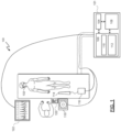
- Fig. 1 shown therein is a schematic diagram depicting a medical system 100.
- the medical diagnosis and treatment system 100 or, simply, the medical system 100 provides for coherent acquisition, integration, and consolidation of multiple forms of acquisition and processing elements designed to be sensitive to a variety of modalities used to acquire and interpret human biological, physiology, and morphological information and to coordinate treatment of various conditions.
- the medical system 100 includes a processing system 101 that is a computer system with the hardware and software to acquire, process, and display medical data and to facilitate control of one or more medical devices, such as intravascular devices.
- the processing system 101 may be a computer workstation that includes at least one processing device, such as a microcontroller or the depicted central processing unit (CPU) 104 and a non-transitory, computer-readable storage medium (illustrated as memory 106) such as a hard drive, random-access-memory (RAM), flash memory, and/or compact disk read-only-memory (CD-ROM or DVD-ROM), etc.
- the processing system 101 may further include an acquisition card 108 to receive and/or process data from multiple medical device modalities.
- the acquisition card 108 may also provide an interface to communicate commands and requests to coupled medical devices.
- the memory 106 may include more than one memory or data storage device and may store data 110 acquired from coupled medical devices and instructions 112.
- the instructions 112 may include executable code that, when executed by the CPU 104 enables a user to view and interact with data received from coupled medical devices and/or data stored remotely and that enables a user to control the coupled medical devices.
- the instructions 112 include executable code to direct the processing system 101 to estimate a restenosis probability value based on information collected at the site of a lesion.
- the instructions 112 include executable code to direct the medical system 100 to perform methods 600, 700, and 800, as described in detail further below.
- the processing system 101 may also include video controller such as a graphics processing unit (GPU), a speaker, and a network communication device such as an Ethernet controller or wireless communication controller.
- GPU graphics processing unit
- Ethernet controller such as an Ethernet controller or wireless communication controller.
- the processing system 101 is programmed to execute steps associated with the medical data acquisition, analysis, estimation, and control described herein. Accordingly, it is understood that any steps related to data acquisition, data processing, estimations based on acquired data, instrument control, and/or other processing or control aspects of the present disclosure may be implemented by the processing system 101 using corresponding instructions stored on or in a non-transitory, computer-readable medium accessible by the processing system.
- the medical system 100 is deployed in a catheter lab having a control room, with the processing system 101 being located in the control room.
- the processing system 101 may be located elsewhere, such as inside the catheter lab, in a centralized area in a medical facility, or at an off-site location accessible by an extended network.
- the catheter lab and control room may be used to perform on a patient any number of medical sensing and treatment procedures known in the art.
- a patient 103, depicted in catheter lab may be undergoing a single modality or a multi-modality procedure either as a single procedure or in combination with one or more sensing procedures.
- an angioplasty procedure may be performed to position a stent in a target location in a target region of the vasculature of the patient 103 having a lesion.
- the patient may be undergoing a percutaneous coronary intervention, performed by a clinician employing the processing system 101.
- intravascular device 114 is a medical imaging device that may be utilized by a clinician to acquire medical imaging data about the patient 103 and/or to provide a treatment to the patient 103.
- the intravascular device 114 may obtain imaging data (including still images, video, etc.) by using ultrasound (e.g., IVUS), OCT, thermal, and/or other imaging techniques.
- the intravascular device 114 may be any form of device, instrument, catheter, guidewire, or probe that is sized and shaped to be positioned within a vessel.
- intravascular device 114 may be combined with a non-imaging component into a single package that is sized and shaped to be positioned within a vessel.
- the IVUS intravascular device 114 is an IVUS catheter that includes one or more sensors such as a phased-array transducer to collect IVUS sensing data.
- the intravascular device 114 may be capable of multi-modality sensing such as both IVUS and intravascular photoacoustic (IVPA) imaging, OCT imaging, pressure sensing, and flow sensing, etc.
- IVPA intravascular photoacoustic
- a patient interface module (PIM) 116 couples the intravascular device 114 to the medical system 100.
- the PIM 116 facilitates the exchange of information between the intravascular device 114 and the processing system 101, serving as a medical device interface therebetween.
- the acquisition card 108 may provide communication between the CPU 104 and the intravascular device 114 by exchanging information with the PIM 116.
- This information includes imaging data transmitted from the intravascular device 114 to the processing system 101 and commands and settings, which may include individual parameter specifications, communicated from the processing system 101 to the PIM 116 and to the intravascular device 114 itself.
- the PIM 116 is operable to receive medical imaging and/or sensing data collected from the patient 103 using the intravascular device 114 and to transmit the received data to a processing system such as the processing system 101.
- a bedside controller 118 is also communicatively coupled to the processing system 101 and provides user control of the particular medical modality (or modalities) being used to diagnose and/or treat the patient 103.
- the bedside controller 118 is a touch screen controller that provides user controls and diagnostic images on a single surface within the field of operation.
- the bedside controller 118 may include both a non-interactive display and separate controls 120 such as physical buttons and/or a joystick, and/or a keyboard and mouse.
- the bedside controller 118 is operable to present control options for the intravascular device 114 and patient imaging data collected therefrom in graphical user interfaces (GUIs).
- GUIs graphical user interfaces
- the medical system 100 provides a medical imaging system interface by which a stent may be observed after deployment of the stent to monitor the success of the deployment, thereby avoiding underdeployment of the stent, and by which an estimate or prediction of a probability of restenosis may be communicated to the clinician. More detail regarding the estimation of a restenosis probability is provided herein.
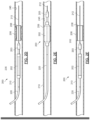
- Figs. 2A-2F are a series of cross-sectional views that illustrate the insertion and use of therapeutic and imaging catheter(s) into a patient.
- the catheter 200 is an integrated catheter, including both imaging and therapeutic capabilities.
- separate catheters or devices are utilized for treatment and imaging.
- the therapeutic treatment is performed using a first catheter is positioned within the illustrated vessel, and the imaging is performed using a separate catheter having imaging capabilities.
- the catheter 200 may include multiple therapeutic modes.
- the catheter 200 may be configured to include a balloon assembly for stent deployment, to provide for lesion ablation, and gather images of the site, and may include specialized structures and transducers to provide these and other features.
- the catheter 200 includes a balloon assembly 202 and an imaging device 203 being sized and shaped for use within a vessel 210 of the patient 103 of Fig. 1 .
- the vessel 210 may be an artery.
- the catheter 200 includes an inner sleeve 204.
- the inner sleeve 204 has high pressure capability greater than 20 ATM, which makes the balloon assembly 202 suitable for non-compliant post dilatation.
- FIGS. 2A-2F illustrate the use of the catheter 200 to access an intravascular lesion 206, assess the intravascular lesion 206, and treat the intravascular lesion 206 using a treatment device, such as an expandable stent 208, according to one embodiment of the present disclosure.
- the catheter 200 is also used to assess the placement of the expandable stent 208 within the vessel 210.
- the assessment of the placement of the expandable stent 208 may be performed by collecting imaging data and other data (e.g., pressure, flow, etc.) both before and after the placement of the stent 208.
- imaging data e.g., pressure, flow, etc.
- Such data may include information describing a tissue type at the site, a plaque type at the site, a type of the stent, and/or the location of the stent and lesion within the vessel.
- the tissue type(s) and plaque type(s) at the site may be collected by imaging with the imaging device 203 using a virtual histology approach, such as those described in one or more of U.S. Pat. No. 6,200,268 titled “VASCULAR PLAQUE CHARACTERIZATION,” U.S. Pat. No. 6,381,350 titled “INTRAVASCULAR ULTRASONIC ANALYSIS USING ACTIVE CONTOUR METHOD AND SYSTEM,” U.S. Pat. No. 7,074,188 titled “SYSTEM AND METHOD OF CHARACTERIZING VASCULAR TISSUE,” U.S. Pat. No.
- the treatment device comprises balloon assembly 202 the expandable stent 208.
- the stent 208 may comprise any of a variety of expandable devices shaped and configured to be carried on the balloon assembly 202 or another part of the catheter for the treatment intravascular lesions.
- the catheter 200 may be configured to deploy other treatments.
- the treatment device may comprise a scaffolding device, a valve device, a filtering device, a stent graft, an ablation device, a drug delivery or an elution device.
- the treatment device may be designed to indefinitely remain in the vessel after removable of the catheter 200. In other instances, the treatment device may be designed for removal along with the catheter 200 or removal at a later time.
- Fig. 2A illustrates the catheter 200 being advanced into a patient's vessel 210.
- a guidewire 212 is fed into the vessel 210.
- a guidewire 212 having a diameter of approximately 0.356 mm (0.014 inches) can be utilized.
- the catheter 200 can then be moved along the guide-wire 212 deeper into the patient's vessel 210.
- the balloon assembly 202 is not inflated and maintains a low profile in an unexpanded condition.
- a distal end 214 of the catheter 200 can be designed to facilitate entry and progress through the vessel 210.
- the distal end 214 may be tapered. As shown in Fig.
- the catheter 200 is pushed into the vessel 210 until the imaging device 203 and a distal junction 216 of the balloon assembly 202 enters the vessel 210.
- the catheter 200 is then pushed further into the vessel 210 until a proximal junction 218 of the balloon assembly 202 enters the vessel 210.
- the catheter 200 is pushed further into the vessel 210, guided along by a guidewire 212, with a proximal shaft 220 of the catheter 200 extending outside the vessel 210 and outside the patient.
- Fig. 2B illustrates the catheter 200 moving through the lesion 206 in the patient's vessel 210.
- the imaging device 203 can be used to detect and assess the lesion 206 to facilitate placement of the stent 208.
- the lesion 206 includes a proximal end 225 and a distal end 230 and has a length L1 extending from the proximal end 225 to the distal end 230 of the lesion 206.
- a clinician can view the data obtained by the imaging device 203 to assess the health of the vessel.
- the imaging data may also relay other vascular characteristics, such as, by way of non-limiting example, the path and/or tortuosity of the vessel 210, information regarding the location of the lesion 206 within the vessel 210, the regularity or irregularity of the vessel walls within the vessel 210, and various characteristics about the blood flow within the vessel 210.
- the imaging data may be processed by the processing system 101 of Fig. 1 to identify the types of tissue and/or plaque present at the site of the lesion 206.
- the catheter 200 Upon visualizing the lesion 206, the catheter 200 is advanced further into the vessel 210 until the balloon assembly 202 is aligned with the occlusion 206.
- the imaging device 203 can continue to image the vessel as the distal end 214 of the catheter 200 travels through the lesion 206, thereby providing the clinician with an accurate assessment of the location of the balloon assembly 202.
- the imaging device 203 is positioned a known distance D1 from the balloon assembly 202, which allows a clinician to advance and/or retract the catheter 200 the known distance to position the balloon assembly 202 relative to whatever portion of the vessel 210 the imaging device 203 is imaging at a given time.
- the imaging device 203 can also be used to facilitate placement of the balloon assembly 202 relative to the lesion 206.
- the lesion 206 is an intravascular occlusion that may require reduction and stenting as a treatment option. As shown in Figs.
- the imaging data relayed by the imaging device 203 can provide information of various anatomic characteristics within the vessel 210, such as, by way of non-limiting example, the length L1 of the lesion 206, the luminal contours and cross-sections of the lesion 206 (e.g., the intraluminal diameter of the vessel 210 proximal, adjacent, and distal to the lesion 206), and characteristics of the blood flow through the lesion 206, etc.
- the clinician can advance the catheter 200 an appropriate distance forward to accurately position the unexpanded balloon assembly 202 and overlying stent 208 within the lesion 206.
- the stent 208 includes a length L2 extending from a proximal stent end 235 to a distal stent end 240.
- the clinician can assess whether the length L2 of the stent is appropriate to treat the lesion 206, which has the length L1. If the stent 208 is comparatively too short or too long to appropriately treat the lesion 206, the catheter 200 may be removed and a correctly-sized stent may be provided, thereby avoiding the potential stent failure, collapse, ineffective treatment, or less effective treatment that may result from implantation of an inappropriately-sized stent.
- Fig. 2C illustrates the expansion of the balloon assembly 202 and the stent 208 within the lesion 206 in the patient's vessel 210.
- the clinician may inflate the balloon assembly 202 by introducing a pressure therein to both compress the plaque or other material causing the lesion 206 and expand the stent 208 to maintain the new patency of the vessel 210 at the location of the lesion 206. As mentioned above, this may be done by pumping an inflation fluid through an inner lumen of the proximal shaft 220 of the catheter 200.
- the stent 208 assumes an expanded condition and compresses the material of the lesion 206 against inner walls of the vessel 210.
- Fig. 2D illustrates the withdrawal of the balloon assembly 202 from the lesion 206 after initial deployment of the stent 208 within the lesion 206.
- the clinician may deflate the balloon assembly 202 and retract or pull back the catheter 200 until the imaging device 203 is positioned proximal to the stent 208.
- the clinician or a processing system can access and use imaging data received by the imaging device 203 as it is pulled back through the deployed stent 208. This imaging data may be referred to as pullback imaging data.
- the imaging data may be used to assess the expansion and deployment of the stent 208. In particular, the imaging data allows the clinician to assess appropriate stent apposition against the lesion 206 and the arterial wall.
- the pullback imaging data and other data may be processed by the processing system 101 to estimate a probability of restenosis.
- the processing system 101 may estimate the restenosis probability based on the deployment of the stent 208 (such as amount of deployment of the stent 208 relative to the diameter of the vessel on either side of the lesion 206), a tissue type or types present at the site of the lesion 206, the type of stent, and the location of the stent 208 within the vessel 210.
- the degree of deployment of the stent 208 may be determined as a percentage of the pre-deployment diameter of the vessel 210 at the site of the lesion 206, as a percentage of a target or desired deployment diameter, or as a percentage of a diameter or average diameter of the vessel 210 on either side of the lesion 206, or as a percentage of the cross-sectional areas before and after the deployment of the stent 208.
- the processing system 101 may determine objectively that there is a high probability of restenosis.
- This restenosis probability value may be communicated to a clinician in a variety of ways.
- a visual indication of the restenosis probability value may be displayed on the bedside controller 118 or the display 122 of Fig. 1 .
- the threshold value may be 60%, 75%, 80%, 95%, or another percentage. While this example estimates the restenosis probability value based on the degree of deployment, in many embodiments, multiple factors are included to estimate or calculate the restenosis probability value.
- the expansion of the stent 208 is insufficient to adequately treat the lesion 206.
- the expansion of the stent 208 may appear to be sufficient to treat the lesion 206 based on angiography imaging or pressure analysis, but is not actually sufficient or is not likely to be maintained in the future.
- pressure measurements taken proximally and distally to the stent 208 after deployment of the stent 208 may indicate a satisfactory level of improvement in the flow through the vessel 210 at the current time.
- the collected imaging data of the site of the stent 208 may indicate a high probability of restenosis.
- imaging data obtained by a pullback of the catheter 200 may provide additional information in assessing the performance, both now and in the future, of the stent 208.
- the stent 208 has not fully expanded to compress the lesion 206 against luminal walls 245 of the vessel 210. Instead, the lesion 206 remains partially intact and capable of at least partially occluding flow through the vessel 210.
- the imaging device 203 can convey this information via imaging data to the clinician and the processing system 101 may estimate the restenosis probability value and communicate it visually and/or by audio to the clinician. For example, when the processing system 101 estimates the restenosis probability value of the stent 208, which is not fully expanded as shown in Fig. 2D , is above a threshold value the processing system may cause a beep or chime to be produced on a speaker coupled to the processing system 101.
- the processing system 101 may cause a notification to be displayed to the clinician.
- the notification or alert such as a visual notification or audio notification, associated with the estimated restenosis probability value may indicate to the clinician that the stent 208 is not positioned satisfactorily and that ameliorative measures should be considered. These ameliorative measures may include performing corrections to the deployment of the stent 208 or performing an alternative procedure, such as an ablation procedure to remove material from the site of the lesion 206.
- the processing system 101 may generate a recommended intervention (e.g., a higher pressure deployment of the stent 208, an ablation process, or a combination thereof, etc.) and communicate the recommendation to the clinician in a user interface provided by the processing system 101.
- a recommended intervention e.g., a higher pressure deployment of the stent 208, an ablation process, or a combination thereof, etc.
- Fig. 2E illustrates the reinsertion and re-expansion of the balloon assembly 202 within the lesion 206 to improve the deployment of the stent 208.
- the placement of the stent 208 may be assessed again, and if the restenosis probability value is still above a threshold additional steps may be taken.
- the clinician may re-advance the catheter 200 and re-position the balloon assembly within the stent 208 and the lesion 206.
- the balloon assembly 202 may be re-inflated at a higher pressure to further expand the stent 208, thereby improving the stent apposition and/or expansion against the luminal walls 245 of the vessel 210.
- Fig. 2F illustrates the withdrawal of the balloon assembly 202 from the lesion 206 after the secondary expansion of the stent 208 within the lesion 206.
- the clinician may once again deflate the balloon assembly 202 and retract the catheter 200 until the imaging device 203 is positioned proximal to the stent 208.
- the processing system 101 may again use the imaging data obtained by the imaging device 203 during the pullback to assess the expansion and deployment of the stent 208 to estimate another restenosis probability value based on the new conditions.
- the estimated restenosis probability value may provide an indication to the clinician that there is appropriate stent apposition against the lesion 206 and expansion within the vessel 210 and that the future performance of the stent 208 is likely to continue without restenosis.
- the processing system 101 may indicate the appropriate deployment of the stent 208 (i.e., appropriate positioning, expansion, and apposition) to the clinician. Then, the clinician may withdraw the catheter 200 from the vessel 210 (and the patient's body). In some embodiments, the processing system 101 may indicate that the deployment of the stent 208 is satisfactory. Similarly, the processing system 101 may simply not provide an indication that the deployment of the stent 208 is unsatisfactory.
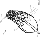
- FIG. 3 illustrates a device 300 including an imaging catheter for imaging a vessel via intravascular ultrasound (IVUS) while using a balloon 302.
- the imaging catheter device 300 may be used as described above in connection with the catheter 200 in Figs. 2A-F .
- the imaging catheter device 300 includes an imaging assembly 304 configured within the balloon 302.
- imaging assembly 304 includes any technology suitable for intravascular imaging such as technologies based on sound, light, or other media.
- the catheter 300 may include an imaging portion 306 (e.g., with conductor wires extending therethrough, surrounding an inflation lumen, guidewire lumen, or both, and extends to distal tip 308.
- the imaging assembly 304 is an IVUS imaging assembly.
- the imaging assembly can be a phased array IVUS imaging assembly or a rotational IVUS imaging assembly.
- an IVUS array is configured to image beyond the distal end of the catheter, i.e., forward-looking IVUS.
- the imaging assembly 304 may use optical coherence tomography (OCT).
- OCT is a medical imaging methodology using a miniaturized near infrared light-emitting probe, and is capable of acquiring micrometer-resolution, three-dimensional images from within optical scattering media (e.g., biological tissue).
- the imaging catheter device 300 includes a catheter 310 with an extended body terminating at a distal tip 308.
- the catheter 310 may have one or more lumens therein such as, for example, a guidewire lumen to allow the catheter 310 of the device 300 to be guided to a treatment site.
- the catheter 310 may include a separate inflation lumen allowing fluid 312 (e.g., air) to be delivered to, and to inflate, balloon 302.
- the catheter 310 may also include the imaging device 304.
- the imaging device 304 is depicted as being located within balloon 302.
- a portion 306 of catheter 310 carries requisite hardware for imaging assembly 304 such as conductors or optical fibers.
- Imaging assembly 304 may operate via any suitable imaging modality including, for example, ultrasound, opto-acoustic imaging, OCT, or others.
- the imaging catheter device 300 may be used as generally described above in connection with Figs. 2A-F . However, the imaging catheter device 300 may be used to obtain at least some imaging data while the balloon 302 is being deployed to place a stent at the site of a lesion.
- Fig. 4 illustrates the imaging catheter device 300 of Fig. 3 with a stent 400 being deployed by the expansion of the balloon 302.
- imaging data is collected based on the reflected signals produced by sound waves 402 emitted from the imaging assembly 304 while the balloon 302 is expanding to place the stent 400.
- collecting imaging data from the site of a lesion may be performed before, after, and during deployment of a stent or other treatment.
- This imaging data may be processed by the processing system 101 to identify tissues and plaque at the site and to characterize the site and/or lesion in terms of physical dimensions. Further, the processing system 101 may estimate a restenosis probability during placement of the stent 400.
- the processing system 101 may provide an indication of the restenosis probability value to a clinician during placement of the stent 400.
- the restenosis probability value calculated during deployment of the stent 400 may be communicated as being a preliminary restenosis value.
- the restenosis probability value may be estimated repeatedly during deployment of the stent 400, such that when the restenosis probability value falls below a threshold value, an indication is provided to a clinician through a user interface to indicate that the probability of restenosis is acceptably small.
- Fig. 5 depicts a user interface 500, according to an embodiment of the present disclosure, that may be provided by the processing system 101 for display by the bedside controller 118 and/or the display 122 of Fig. 1 .
- the user interface 500 may also be referred to as a screen display.
- the user interface500 may include multiple tabs or be accessible as a tab within an overall user interface associated with the processing system 101 and or the intravascular device 114 of the medical system 100 illustrated in Fig. 1 .
- the user interface 500 may include a close-up window 502 that displays a portion of the imaging data 504 obtained from a site of a stent placement. When rendered in the close-up window 502 in a display, the imaging data 504 includes a depiction of the stent 506 within the vessel.
- the stent 506 is at least partially deployed.
- the displayed portion of imaging data 504 may show the stent 506 in a nearly cross-sectional view.
- the close-up window 502 may enable a clinician to visualize the placement of a stent, such as the stent 208 or 400 of Figs. 2A-F and 4, respectively.
- the clinician may also be able to see the cross-sectional configuration of the vessel at the site of the stent 506.
- Vessels may deviate from a generally circular cross-section to varying degrees that may not be observed externally, but may be observed using intravascular imaging devices.
- the user interface 500 may also include a full view window 508 that may display the full current view of the rendered imaging data 504.
- the windows 502 and 508 may include "live" imaging data.
- one or both of the windows 502 and 508 may display non-live or recorded imaging data.
- different modes of images may be displayed in the windows 502 and 508. For example, imaging data obtained in a manner to optimize the depiction of plaque may be shown in the window 502, while imaging data obtained in manner to optimize the depiction of tissue may be shown in the window 508.
- the imaging data may be obtained by alternating between imaging modes.
- the imaging modes may be provided by processing a single set of imaging data in different ways or the modes may be provided by alternating between settings and parameters implemented by the imaging device within the catheter to best capture certain features at the imaging site.
- the imaging techniques described in U.S. Provisional Patent Application No. 61/903,764, filed November 13, 2013 and titled "Visually Optimized Intravascular Imaging and Associated Devices, Systems, and Methods," may be utilized.
- a clinician may apply subjective judgment, based on experience, to assess the quality of the placement of the stent.
- the user interface 500 further includes a stent placement information window 510.
- the stent window 510 may be used to communicate objective information regarding the placement of a stent within a patient's vessel. The information recording the placement of the stent is based on physiological measurements taken by sensors within the vessel, such as intravascular imaging data.
- the clinician may interact with the user interface 500 to enable or disable the estimation of the probability of restenosis.
- the window 510 include an auto button 512A by which the user of the user interface 500, e.g., a clinician, may affirmatively request that an estimated restenosis probability value is automatically and continuously calculated by the processing system 101 as physiological data becomes available.
- the physiological data may become available by being collected using a catheter, such as an IVUS imaging catheter, and/or by being accessed from a memory, such as a networked storage device having physiological data stored thereon.
- the manual button 512B may be selected to limit the estimation process.
- a manual mode is activated, in which an estimated restenosis probability value is calculated when the update button 512C is selected by the clinician.
- Buttons 512A-C may be selected by clicking a mouse, entering an associated keystroke on a keyboard, and/or by touching a touch-screen.
- the stent placement information window 510 includes an estimated restenosis probability area 514 that may display an indication of a most current estimated restenosis probability value 516.
- the estimated restenosis probability value 516 may be communicated through the user interface 500 in a variety of ways, only some of which are described herein.
- the restenosis probability value 516 may be provided as a numerical value.
- a qualitative description of the quantitative, estimated restenosis probability value 516 may be provided by applying a plurality of value brackets.
- the processing system 101 may communicate qualitative descriptions of the estimated restenosis probability value that may be more easily interpreted by the clinician than the actual estimated restenosis probability value itself.
- a color may be displayed to indicate the bracket in which a most recent estimated restenosis probability value belongs, e.g., "red,” “yellow,” or "green.”
- the user interface 500 may include audio cues to indicate an estimated restenosis probability value.
- the user interface 500 may cause an alert or a beep to be generated through a speaker whenever the most recent estimated restenosis probability value is above a threshold value.
- the estimated restenosis probability value 516 may communicate that the current placement of a stent may not be providing adequate compensation for a lesion and/or may not provide adequate compensation for the lesion in the future.
- the estimated restenosis probability value 516 may indicate that, although flow through the stent is improved after initial placement, the benefits of the stent may not last unless additional steps are taken.
- the stent placement information window 516 also includes a recommended intervention area 518, in some embodiments.
- a particular intervention may be determined by the processing system 101 to best improve the performance of a stent
- the determined means of achieving that improvement may be displayed for communication in the user interface 500.
- the processing system 101 has determined that the estimated restenosis probability value is above a threshold value and that redeploying the stent by re-expanding a balloon at a distal portion of the catheter using an increased pressure may improve the performance of the stent in the future.
- the processing system 101 indicates that an ablation treatment is not recommended.
- more than one intervention may be displayed to a user with accompanying indications of whether the intervention is likely to improve the performance of the stent in the future.
- a single recommended intervention may be displayed in the recommended intervention area 518.
- the user interface 500 may include further buttons or user interface elements to enable a clinician to program threshold values that may be used with the estimated restenosis probability value to customize the indications of stent placement performance.
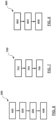
- the method 600 illustrates a method for treating a vessel of the patient 103 of Fig. 1 using the medical system 100.
- the method 600 is illustrated as a plurality of enumerated steps or operations. Embodiments of the method 600 may include additional steps or operations before, after, in between, or as part of the enumerated steps.
- the steps of the method 600 may be performed using hardware such as the intravascular device 114, the processing system 101 including the CPU 104, and the display 122 or display of the bedside controller 118.
- the instructions for performing some or all of the operations of the method 600 may be stored as executable code on a non-transitory computer readable medium such as the memory 106 of Fig. 1 .
- a processing device such as the CPU 104 of the processing system 101 estimates a restenosis probability value based on the intravascular ultrasound imaging data of the placement of the stent at the site of the lesion.
- Many algorithms may be used to process the collected imaging data obtained at the site of the lesion and other information to generate an objective measure of restenosis probability.
- the processing device estimates the restenosis probability value based on the presence of gaps between the stent and the walls of the vessel or the cross-sectional area through the stent (including the shape and/or size of the area and the uniformity of the cross-sectional area through the stent).
- the processing device may estimate the restenosis probability value based on the degree of curvature in the vessel in areas proximal to the stent.
- the estimation of the restenosis probability value may be based on physiology measurements such as pressure data and/or flow data. For example, pressure information may be obtained at locations before and after the stent and at various points within the stent. This pressure information may be used to assess the performance of the stent and may be used in estimates of the restenosis probability value.
- pressure information may be used by the processing device along with the imaging data to generate the estimated restenosis probability value.
- a catheter is inserted into a lumen of the vessel. This may be done as shown in Figs. 2A and 2B as described herein.
- the catheter may include a stent placement assembly, like the balloon assembly 202 of Figs. 2A-F or the balloon 302 shown in Figs. 3 and 4 as described herein, and an intravascular ultrasound imaging device, such as the imaging assembly 304, also of Figs. 3 and 4 .
- the catheter may be inserted by manual control of the catheter by a clinician, the catheter may be inserted using robotic control at the direction of the clinician, or the catheter may be inserted using automatic robotic control wherein the catheter is steered by the processing system 101 to the site of the lesion.
- the catheter may be a steerable intravascular device 114, coupled to a PIM 116 that received commands from the processing system 101, or directly from the bedside control 118, to steer the catheter's tip and direct the catheter into and out of a vessel.
- the stent placement assembly may be activated to place the stent at the site of the lesion within the lumen of the vessel, as depicted in Fig. 2C .
- the stent may be deployed such that it expands against the walls of the lumen to improve flow within the vessel.
- intravascular ultrasound imaging data is collected using the intravascular ultrasound imaging device of the catheter. This may be done while performing a pullback of the catheter, such that imaging data is obtained along the vessel from a distal side of the stent or the lesion and to a proximal side of the stent or the lesion.
- the imaging data includes information about the placement of the stent at the site of the lesion and may be processed by the processing system 101 to provide specific information regarding tissue types, plaque presence and/or types, and information regarding the location of the stent within the vessel (e.g., whether the vessel include pronounced bends, the stent diameters on either side of the stent, etc.).
- the information may include information regarding the cross-sectional area of the vessel before and after the stent and within the stent.
- the intravascular ultrasound imaging device may provide information to indicate this to the clinician.
- the imaging data may include information enabling the processing system 101 to interpret and analyze the gap and provide visualization of the gap in a display in some embodiments.
- a processing device such as the CPU 104 of the processing system 101 may estimate a restenosis probability value based on the intravascular ultrasound imaging data of the placement of the stent at the site of the lesion.
- Many algorithms may be used to process the collected imaging data obtained at the site of the lesion and other information to generate an objective measure of restenosis probability.
- the processing device estimates the restenosis probability value based on the presence of gaps between the stent and the walls of the vessel, the cross-sectional area through the stent (including the shape and/or size of the area and the uniformity of the cross-sectional area through the stent).
- the processing device may also estimate the restenosis probability value based on tissue types at the site, plaque types at the site and/or plaque presence and geometry, a type of the stent, and/or the location of the stent within the vessel, whether the lesion extends beyond the stent, etc. In some embodiments, the processing device may estimate the restenosis probability value based on the degree of curvature in the vessel in areas proximal to the stent. Additionally, in some embodiments the data other than imaging data may be used to provide information regarding the performance of the stent. For example, pressure information and/or flow information may be obtained at locations before and after the stent and at various points within the stent. This pressure and flow information may be used to assess the performance of the stent and may be used in estimates of the restenosis probability value. In some embodiments, pressure information may be used by the processing device along with the imaging data to generate the estimated restenosis probability value.
- an indication of the estimated restenosis probability value is communicated to a clinician.
- the processing system 101 may cause an indication of the estimated restenosis probability value to be visualized on the display 122 or on a touchscreen display of the bedside controller 118.
- the processing system 101 may cause a user interface, such as the user interface 500 to be displayed.
- the user interface 500 includes a stent placement information window 510 as described herein.
- the estimated restenosis probability value 516 may be displayed in the estimated restenosis probability area 514 is a numerical value, is a color, as text, or as a combination thereof.
- the estimated restenosis probability value may be interpreted by the processing system 101 before display to the clinician.
- the estimated restenosis probability value may be compared with a plurality of brackets that map to descriptions of estimated restenosis probability, such as "poor,” “fair,” “good,” etc.
- the indication of the estimated restenosis probability value may be communicated to the clinician is a sound, such as a beep, a chime, or an alarm to indicate that restenosis is likely or unlikely as indicated by the imaging data and other information obtained by the catheter at the site of the lesion after placement of the stent.
- the clinician may reinsert the stent deployment assembly within the stent and apply pressure again to deploy the stent, as shown in Figs. 2E and 2F . Thereafter, data may be collected and the restenosis probability may be calculated again to predict future stent performance in view of the redeployment.
- Fig. 7 shown therein is a flowchart of a method 700 of treating a vessel within a patient. Like the method 600 of Fig. 6 , the method 700 is illustrated as a plurality of steps or operations. Additional steps may be performed before, after, in between, or as part of these enumerated steps. Steps of the method 700 may be performed by the medical system 100 of Fig. 1 .
- An example of the method 700 may begin at step 702 in which a catheter is positioned at a site of a lesion within a lumen of the vessel.
- the catheter includes a stent placement assembly.
- the stent placement assembly is activated to place the stent at the site of the lesion within the lumen of the vessel.
- the catheter may include a balloon 302 that may be deployed and the fluidic pressure to cause the stent to expand against the luminal walls of the vessel.
- the stent may be deployed as illustrated in Fig. 4 by the stent 400. Once deployed, the stent may restore flow through the vessel.
- a restenosis probability value is estimated based on the placement of the stent at the site of the lesion, at step 706.
- the restenosis probability value may be estimated by the processing system 101 of Fig. 1 .
- the CPU 104 may receive imaging data and/or other data obtained within the vessel at the placement of the stent and may analyze the data to determine tissue types, plaque types, the location of the stent within the vessel including the cross-section of the vessel at multiple points within the stent and the degree of bending of the vessel or adjoining vessels near the stent. Additionally, the CPU 104 may receive imaging data and/or other data obtained prior to the placement of the stent.
- the CPU 104 may execute algorithms and methods stored as executable code in the instructions 112 on the memory 106.
- an indication of the estimated restenosis probability value may be communicated to a clinician to inform the clinician that an intervention should be performed so that long-term future benefits of the stent may be achieved.
- the processing system 101 may determine that the estimated restenosis probability value would be increased by inserting the balloon 302 into the stent again and re-inflating the balloon using a higher pressure than originally employed.
- the processing system 101 may determine that the estimated restenosis probability value would be increased by inserting an ablation device within the stent and performing an ablation process to remove some of the plaque from the site of the lesion.
- the stent may be redeployed using a higher pressure or using the same pressure after the ablation process.
- data may be obtained at the placement of the stent to assess and re-assess the restenosis probability by an estimation algorithm.
- the processing system 101 may determine from the imaging data that a stent is deployed, in at least some portion of the stent, to only a fraction, such as 65%, of its maximum diameter.
- Other algorithms may include different threshold values and may operate on more variables extracted from the imaging data.
- the method 800 includes a step 802 in which imaging data is received.
- the imaging data is obtained by, and received from, an imaging device on a catheter at a placement site of a stent within a lumen of a vessel of a patient.
- the processing system 101 of Fig. 1 may receive imaging data obtained by the intravascular device 114.
- the imaging data may have undergone some processing by the PIM 116 and/or the acquisition card 108 prior to reception by the CPU 104 of the processing system 101.
- the processing system estimates the restenosis probability value based on the imaging data obtained by the imaging device.
- the estimated restenosis probability value may be based on the placement of the stent at the site of a lesion.
- an indication of the estimated restenosis probability value may be communicated to a clinician.
- the indication may be communicated in many different ways as described herein.
- the processing system 101 may send information to a display to communicate the estimated restenosis probability value.
- a numerical representation of the estimated restenosis probability value may be displayed on a display coupled to the processing system 101, a sound may be emitted from the speaker of the processing system 101, etc.
- intervention recommendation may be determined and provided to a clinician when the stent is determined to be underdeployed, or otherwise performing unsatisfactorily, based on the imaging data obtained by the imaging device.
- the processing system may receive non-imaging data, such as pressure data or other physiological data, obtained by another sensor or sensors included in the catheter.
- the estimated restenosis probability value may be calculated based on the non-imaging data or on a combination of imaging data and non-imaging data.
- instructions for performing the operations included in examples of the method 800 may be stored in a non-transitory computer readable medium, such as the memory 106 of the processing system 101.
- a non-transitory computer readable medium such as the memory 106 of the processing system 101.
- embodiments of the present disclosure include systems having processing devices, such as the CPU 104 or the processing system 101 more generally, that perform one or more of the methods 600, 700, and 800 when instructions corresponding to one or more of the enumerated steps of these methods are provided as executable code stored on the non-transitory computer readable medium.
- Embodiments of the present disclosure provide for the assessment of stents after deployment within a vessel.
- a probability of restenosis may be estimated based on objective information obtained from the data.
- the processing system may provide an objective indication of current and/or future stent performance.
- the processing system may recommend one or more interventions to improve the current and/or future performance of the stent.
- one or more future interventions may be avoided. Avoiding unnecessary interventions is beneficial to both patients and clinicians.
Landscapes
- Health & Medical Sciences (AREA)
- Life Sciences & Earth Sciences (AREA)
- Engineering & Computer Science (AREA)
- Biomedical Technology (AREA)
- Public Health (AREA)
- General Health & Medical Sciences (AREA)
- Veterinary Medicine (AREA)
- Animal Behavior & Ethology (AREA)
- Heart & Thoracic Surgery (AREA)
- Medical Informatics (AREA)
- Pathology (AREA)
- Surgery (AREA)
- Molecular Biology (AREA)
- Physics & Mathematics (AREA)
- Biophysics (AREA)
- Nuclear Medicine, Radiotherapy & Molecular Imaging (AREA)
- Radiology & Medical Imaging (AREA)
- Vascular Medicine (AREA)
- Cardiology (AREA)
- Transplantation (AREA)
- Oral & Maxillofacial Surgery (AREA)
- Physiology (AREA)
- Hematology (AREA)
- Computer Vision & Pattern Recognition (AREA)
- Data Mining & Analysis (AREA)
- Databases & Information Systems (AREA)
- Epidemiology (AREA)
- Primary Health Care (AREA)
- Ultra Sonic Daignosis Equipment (AREA)
- Endoscopes (AREA)
Description
- The present disclosure is generally related to devices and systems used for assessment of vessels, and in particular, to the assessment of the severity of blockage or other restrictions to the flow of fluid through a vessel, the treatment thereof, and the recurrence thereof.
- Intravascular imaging systems and other intravascular physiology measurement systems are widely used in interventional cardiology as diagnostic tools for a diseased vessel, such as an artery, within the human body. Various sensors may be placed on a catheter and positioned in the body. One type of imaging system is an intravascular ultrasound (IVUS) system. In one example, a phased array IVUS device includes a number of transducers that are passed into a vessel and guided to an area to be imaged. The transducers emit ultrasonic waves in order to create an image of the vessel of interest. The ultrasonic waves are partially reflected by discontinuities arising from tissue structures (such as the various layers of the vessel wall), red blood cells, and other features of interest. Echoes from the reflected waves are received by the transducer and passed along to an IVUS imaging system. The imaging system processes the received ultrasound echoes to produce a cross-sectional image of the vessel where the device is placed.
- Intravascular imaging systems are often used to detect arterial occlusions that can be relieved through use of a balloon catheter. A balloon catheter is a type of catheter with a balloon disposed near the tip. The balloon catheter is designed to be inserted into a patient's artery and positioned to a spot where an occlusion was detected through use of an intravascular imaging system. Upon reaching the detected occlusion, the balloon is inflated to compress the material causing the occlusion. In some instances, the balloon catheter is utilized to deploy a stent. In that regard, inflation of the balloon causes the stent to expand and deploy the stent within the vessel.
- In some instances, an imaging system may be used to image the site of a stent in effort to observe, based on clinician experience, whether the placement of the stent is adequate. However, such current approaches have not been entirely satisfactory. Accordingly, there remains a need for improved devices, systems, and methods of objectively evaluating risk associated with and likelihood of success for one or more available treatment options for the vessel.
- For example, the aspect of restenosis as a risk is addressed in Feyer de P. J. et al: "Reference chart derived from post-stent implantation intravascular ultrasound prediction of 6-month expected restenosis on quantitative coronary angiographs" Circulation, Lippincott Williams & Wilkins, US, vol. 100, no. 17, 26 October 1999 (1999-10-26), pages 1777-1783.
- The invention is defined by the claims. The present disclosure provides devices and, systems, for assessing and treating an intravascular lesion and for assessing the efficacy of the treatment, for use in the methods described for exemplification. As a result, the surgical process and treatment of the patient are improved by estimating the future performance of the treatment, which may be used to perform additional interventions right then, rather than in a subsequent medical procedure at a later time. Aspects of the present disclosure may reduce follow-up procedures and provide improved outcomes for the patients.
- One exemplification includes a method of treating a vessel within a patient. The method includes inserting a catheter including a stent placement assembly and an intravascular ultrasound imaging device into a lumen of the vessel, positioning the catheter at a site of a lesion within the lumen of the vessel, activating the stent placement assembly to place the stent at the site of the lesion within the lumen of the vessel, and collecting intravascular ultrasound imaging data of the placement of the stent at the site of the lesion using the intravascular ultrasound imaging device disposed on the catheter. The method further includes estimating a restenosis probability value based on the intravascular ultrasound imaging data of the placement of the stent at the site of the lesion. The method also includes communicating the estimated restenosis probability value to a clinician.
- Implementations may include one or more of the following features. The method further includes imaging a lumen of the vessel with the imaging device as the catheter is advanced or retracted through the vessel and identifying and imaging a lesion within the lumen of the vessel with the imaging device. The catheter includes the intravascular imaging device on a distal portion of the catheter. The estimating the restenosis probability value includes estimating the restenosis probability value based on at least one of a tissue type at the site, a plaque type at the site, a type of the stent, or location of the stent within the vessel.
- One further exemplification includes another method of treating a vessel within a patient. The method includes positioning a catheter at a site of a lesion within a lumen of the vessel, the catheter including a stent placement assembly, activating the stent placement assembly to place the stent at the site of the lesion within the lumen of the vessel, and estimating a restenosis probability value based on the placement of the stent at the site of the lesion.
- Another general aspect includes a medical diagnosis and treatment system. The system includes a non-transitory, computer-readable medium to store instructions thereon and a processing device, in communication with the medium. The processing device executes the instructions to perform operations including receiving imaging data obtained by an imaging device on a catheter at a placement site of a stent within a lumen of a vessel of a patient and estimating a restenosis probability value based on the placement of the stent at the placement site, the placement site corresponding to a location of a lesion of the vessel. Some implementations of these aspects include corresponding computer systems, apparatus, and computer programs recorded on one or more computer storage devices coupled to one or more processing devices, each configured to perform or implement the actions of the methods.
- Additional aspects, features, and advantages of the present disclosure will become apparent from the following detailed description.
- Illustrative embodiments of the present disclosure will be described with reference to the accompanying drawings, of which:
-
Fig. 1 is a diagrammatic view of a medical system for treating a vessel of a patient. -
Figs. 2A, 2B, 2C ,2D, 2E, and 2F are diagrams showing an illustrative insertion of a catheter into a vessel of a patient. -
Fig. 3 is a diagrammatic, partially cross-sectional view of an imaging catheter device. -
Fig. 4 is a perspective view of the imaging catheter device ofFig. 3 showing the stent thereon. -
Fig. 5 is a visual depiction of a user interface provided by a medical system. -
Fig. 6, 7, and 8 are flow diagrams of methods of treating a vessel of the patient. - These accompanying drawings will be better understood by reference to the detailed description that follows.
- For the purposes of promoting an understanding of the principles of the present disclosure, reference will now be made to the embodiments illustrated in the drawings, and specific language will be used to describe the same. It is nevertheless understood that no limitation to the scope of the disclosure is intended. Any alterations and further modifications to the described devices, systems, and methods, and any further application of the principles of the present disclosure are fully contemplated and included within the present disclosure as would normally occur to one skilled in the art to which the disclosure relates. In particular, it is fully contemplated that the features, components, and/or steps described with respect to one embodiment may be combined with the features, components, and/or steps described with respect to other embodiments of the present disclosure. For the sake of brevity, however, the numerous iterations of these combinations will not be described separately.
- Referring now to
Fig. 1 , shown therein is a schematic diagram depicting a medical system 100. In general, the medical diagnosis and treatment system 100 or, simply, the medical system 100 provides for coherent acquisition, integration, and consolidation of multiple forms of acquisition and processing elements designed to be sensitive to a variety of modalities used to acquire and interpret human biological, physiology, and morphological information and to coordinate treatment of various conditions. In one embodiment, the medical system 100 includes a processing system 101 that is a computer system with the hardware and software to acquire, process, and display medical data and to facilitate control of one or more medical devices, such as intravascular devices. The processing system 101 may be a computer workstation that includes at least one processing device, such as a microcontroller or the depicted central processing unit (CPU) 104 and a non-transitory, computer-readable storage medium (illustrated as memory 106) such as a hard drive, random-access-memory (RAM), flash memory, and/or compact disk read-only-memory (CD-ROM or DVD-ROM), etc. The processing system 101 may further include an acquisition card 108 to receive and/or process data from multiple medical device modalities. The acquisition card 108 may also provide an interface to communicate commands and requests to coupled medical devices. The memory 106 may include more than one memory or data storage device and may store data 110 acquired from coupled medical devices and instructions 112. The instructions 112 may include executable code that, when executed by the CPU 104 enables a user to view and interact with data received from coupled medical devices and/or data stored remotely and that enables a user to control the coupled medical devices. The instructions 112 include executable code to direct the processing system 101 to estimate a restenosis probability value based on information collected at the site of a lesion. In some embodiments, the instructions 112 include executable code to direct the medical system 100 to performmethods - In some embodiments, the processing system 101 is programmed to execute steps associated with the medical data acquisition, analysis, estimation, and control described herein. Accordingly, it is understood that any steps related to data acquisition, data processing, estimations based on acquired data, instrument control, and/or other processing or control aspects of the present disclosure may be implemented by the processing system 101 using corresponding instructions stored on or in a non-transitory, computer-readable medium accessible by the processing system.
- In the depicted embodiment, the medical system 100 is deployed in a catheter lab having a control room, with the processing system 101 being located in the control room. In other embodiments, the processing system 101 may be located elsewhere, such as inside the catheter lab, in a centralized area in a medical facility, or at an off-site location accessible by an extended network. The catheter lab and control room may be used to perform on a patient any number of medical sensing and treatment procedures known in the art. A patient 103, depicted in catheter lab, may be undergoing a single modality or a multi-modality procedure either as a single procedure or in combination with one or more sensing procedures. For example, an angioplasty procedure may be performed to position a stent in a target location in a target region of the vasculature of the patient 103 having a lesion. The patient may be undergoing a percutaneous coronary intervention, performed by a clinician employing the processing system 101.
- In the illustrated embodiment of
Fig. 1 , intravascular device 114 is a medical imaging device that may be utilized by a clinician to acquire medical imaging data about the patient 103 and/or to provide a treatment to the patient 103. For instance, the intravascular device 114 may obtain imaging data (including still images, video, etc.) by using ultrasound (e.g., IVUS), OCT, thermal, and/or other imaging techniques. The intravascular device 114 may be any form of device, instrument, catheter, guidewire, or probe that is sized and shaped to be positioned within a vessel. In some embodiments, intravascular device 114 may be combined with a non-imaging component into a single package that is sized and shaped to be positioned within a vessel. As illustrated, the IVUS intravascular device 114 is an IVUS catheter that includes one or more sensors such as a phased-array transducer to collect IVUS sensing data. In some embodiments, the intravascular device 114 may be capable of multi-modality sensing such as both IVUS and intravascular photoacoustic (IVPA) imaging, OCT imaging, pressure sensing, and flow sensing, etc. - In the depicted embodiment, a patient interface module (PIM) 116 couples the intravascular device 114 to the medical system 100. The PIM 116 facilitates the exchange of information between the intravascular device 114 and the processing system 101, serving as a medical device interface therebetween. The acquisition card 108 may provide communication between the CPU 104 and the intravascular device 114 by exchanging information with the PIM 116. This information includes imaging data transmitted from the intravascular device 114 to the processing system 101 and commands and settings, which may include individual parameter specifications, communicated from the processing system 101 to the PIM 116 and to the intravascular device 114 itself. Thus, the PIM 116 is operable to receive medical imaging and/or sensing data collected from the patient 103 using the intravascular device 114 and to transmit the received data to a processing system such as the processing system 101.
- A bedside controller 118 is also communicatively coupled to the processing system 101 and provides user control of the particular medical modality (or modalities) being used to diagnose and/or treat the patient 103. In the current embodiment, the bedside controller 118 is a touch screen controller that provides user controls and diagnostic images on a single surface within the field of operation. In alternative embodiments, however, the bedside controller 118 may include both a non-interactive display and separate controls 120 such as physical buttons and/or a joystick, and/or a keyboard and mouse. In the integrated medical system 100, the bedside controller 118 is operable to present control options for the intravascular device 114 and patient imaging data collected therefrom in graphical user interfaces (GUIs).
- The medical system 100 provides a medical imaging system interface by which a stent may be observed after deployment of the stent to monitor the success of the deployment, thereby avoiding underdeployment of the stent, and by which an estimate or prediction of a probability of restenosis may be communicated to the clinician. More detail regarding the estimation of a restenosis probability is provided herein.
-
Figs. 2A-2F are a series of cross-sectional views that illustrate the insertion and use of therapeutic and imaging catheter(s) into a patient. In some embodiments, thecatheter 200 is an integrated catheter, including both imaging and therapeutic capabilities. In other embodiments, separate catheters or devices are utilized for treatment and imaging. In such embodiments, the therapeutic treatment is performed using a first catheter is positioned within the illustrated vessel, and the imaging is performed using a separate catheter having imaging capabilities. Additionally, in some embodiments thecatheter 200 may include multiple therapeutic modes. For example, thecatheter 200 may be configured to include a balloon assembly for stent deployment, to provide for lesion ablation, and gather images of the site, and may include specialized structures and transducers to provide these and other features. - As illustrated in
Figs. 2A-2F , thecatheter 200 includes aballoon assembly 202 and animaging device 203 being sized and shaped for use within avessel 210 of the patient 103 ofFig. 1 . In some embodiments, thevessel 210 may be an artery. As illustrated, thecatheter 200 includes aninner sleeve 204. In some embodiments, theinner sleeve 204 has high pressure capability greater than 20 ATM, which makes theballoon assembly 202 suitable for non-compliant post dilatation. For example,Figs. 2A-2F illustrate the use of thecatheter 200 to access anintravascular lesion 206, assess theintravascular lesion 206, and treat theintravascular lesion 206 using a treatment device, such as anexpandable stent 208, according to one embodiment of the present disclosure. Thecatheter 200 is also used to assess the placement of theexpandable stent 208 within thevessel 210. The assessment of the placement of theexpandable stent 208 may be performed by collecting imaging data and other data (e.g., pressure, flow, etc.) both before and after the placement of thestent 208. Such data may include information describing a tissue type at the site, a plaque type at the site, a type of the stent, and/or the location of the stent and lesion within the vessel. For example, the tissue type(s) and plaque type(s) at the site may be collected by imaging with theimaging device 203 using a virtual histology approach, such as those described in one or more ofU.S. Pat. No. 6,200,268 titled "VASCULAR PLAQUE CHARACTERIZATION,"U.S. Pat. No. 6,381,350 titled "INTRAVASCULAR ULTRASONIC ANALYSIS USING ACTIVE CONTOUR METHOD AND SYSTEM,"U.S. Pat. No. 7,074,188 titled "SYSTEM AND METHOD OF CHARACTERIZING VASCULAR TISSUE,"U.S. Pat. No. 7,175,597 titled "NON-INVASIVE TISSUE CHARACTERIZATION SYSTEM AND METHOD,"U.S. Pat. No. 7,215,802 titled "SYSTEM AND METHOD FOR VASCULAR BORDER DETECTION,"U.S. Pat. No. 7,359,554 titled "SYSTEM AND METHOD FOR IDENTIFYING A VASCULAR BORDER," and/orU.S. Pat. No. 7,463,759 titled "SYSTEM AND METHOD FOR VASCULAR BORDER DETECTION". - In the pictured embodiment, the treatment device comprises
balloon assembly 202 theexpandable stent 208. In other embodiments, thestent 208 may comprise any of a variety of expandable devices shaped and configured to be carried on theballoon assembly 202 or another part of the catheter for the treatment intravascular lesions. Further, thecatheter 200 may be configured to deploy other treatments. For example, the treatment device may comprise a scaffolding device, a valve device, a filtering device, a stent graft, an ablation device, a drug delivery or an elution device. In some instances, the treatment device may be designed to indefinitely remain in the vessel after removable of thecatheter 200. In other instances, the treatment device may be designed for removal along with thecatheter 200 or removal at a later time. -
Fig. 2A illustrates thecatheter 200 being advanced into a patient'svessel 210. Initially, aguidewire 212 is fed into thevessel 210. In one example, aguidewire 212 having a diameter of approximately 0.356 mm (0.014 inches) can be utilized. Thecatheter 200 can then be moved along the guide-wire 212 deeper into the patient'svessel 210. During insertion of thecatheter 200 into thevessel 210, theballoon assembly 202 is not inflated and maintains a low profile in an unexpanded condition. Adistal end 214 of thecatheter 200 can be designed to facilitate entry and progress through thevessel 210. For example, thedistal end 214 may be tapered.
As shown inFig. 2A , thecatheter 200 is pushed into thevessel 210 until theimaging device 203 and adistal junction 216 of theballoon assembly 202 enters thevessel 210. Thecatheter 200 is then pushed further into thevessel 210 until aproximal junction 218 of theballoon assembly 202 enters thevessel 210. Thereafter, thecatheter 200 is pushed further into thevessel 210, guided along by aguidewire 212, with aproximal shaft 220 of thecatheter 200 extending outside thevessel 210 and outside the patient. -
Fig. 2B illustrates thecatheter 200 moving through thelesion 206 in the patient'svessel 210. Theimaging device 203 can be used to detect and assess thelesion 206 to facilitate placement of thestent 208. Thelesion 206 includes aproximal end 225 and adistal end 230 and has a length L1 extending from theproximal end 225 to thedistal end 230 of thelesion 206. As thecatheter 200 traverses thevessel 210, a clinician can view the data obtained by theimaging device 203 to assess the health of the vessel. The imaging data may also relay other vascular characteristics, such as, by way of non-limiting example, the path and/or tortuosity of thevessel 210, information regarding the location of thelesion 206 within thevessel 210, the regularity or irregularity of the vessel walls within thevessel 210, and various characteristics about the blood flow within thevessel 210. The imaging data may be processed by the processing system 101 ofFig. 1 to identify the types of tissue and/or plaque present at the site of thelesion 206. Upon visualizing thelesion 206, thecatheter 200 is advanced further into thevessel 210 until theballoon assembly 202 is aligned with theocclusion 206. Theimaging device 203 can continue to image the vessel as thedistal end 214 of thecatheter 200 travels through thelesion 206, thereby providing the clinician with an accurate assessment of the location of theballoon assembly 202. In particular, theimaging device 203 is positioned a known distance D1 from theballoon assembly 202, which allows a clinician to advance and/or retract thecatheter 200 the known distance to position theballoon assembly 202 relative to whatever portion of thevessel 210 theimaging device 203 is imaging at a given time. - The
imaging device 203 can also be used to facilitate placement of theballoon assembly 202 relative to thelesion 206. In the illustrated example, thelesion 206 is an intravascular occlusion that may require reduction and stenting as a treatment option. As shown inFigs. 2B and 2C , as theimaging device 203 travels through the lesion, the imaging data relayed by theimaging device 203 can provide information of various anatomic characteristics within thevessel 210, such as, by way of non-limiting example, the length L1 of thelesion 206, the luminal contours and cross-sections of the lesion 206 (e.g., the intraluminal diameter of thevessel 210 proximal, adjacent, and distal to the lesion 206), and characteristics of the blood flow through thelesion 206, etc. Using this imaging data, the clinician can advance thecatheter 200 an appropriate distance forward to accurately position theunexpanded balloon assembly 202 andoverlying stent 208 within thelesion 206. Thestent 208 includes a length L2 extending from a proximal stent end 235 to adistal stent end 240. The clinician can assess whether the length L2 of the stent is appropriate to treat thelesion 206, which has the length L1. If thestent 208 is comparatively too short or too long to appropriately treat thelesion 206, thecatheter 200 may be removed and a correctly-sized stent may be provided, thereby avoiding the potential stent failure, collapse, ineffective treatment, or less effective treatment that may result from implantation of an inappropriately-sized stent. -
Fig. 2C illustrates the expansion of theballoon assembly 202 and thestent 208 within thelesion 206 in the patient'svessel 210. After the clinician advances theballoon assembly 202 and the stent 208 (in an unexpanded condition) appropriately within thelesion 206, the clinician may inflate theballoon assembly 202 by introducing a pressure therein to both compress the plaque or other material causing thelesion 206 and expand thestent 208 to maintain the new patency of thevessel 210 at the location of thelesion 206. As mentioned above, this may be done by pumping an inflation fluid through an inner lumen of theproximal shaft 220 of thecatheter 200. As theballoon assembly 202 is inflated under a pressure, typically in the range of 15-25 ATM, thestent 208 assumes an expanded condition and compresses the material of thelesion 206 against inner walls of thevessel 210. -
Fig. 2D illustrates the withdrawal of theballoon assembly 202 from thelesion 206 after initial deployment of thestent 208 within thelesion 206. The clinician may deflate theballoon assembly 202 and retract or pull back thecatheter 200 until theimaging device 203 is positioned proximal to thestent 208. The clinician or a processing system can access and use imaging data received by theimaging device 203 as it is pulled back through the deployedstent 208. This imaging data may be referred to as pullback imaging data. The imaging data may be used to assess the expansion and deployment of thestent 208. In particular, the imaging data allows the clinician to assess appropriate stent apposition against thelesion 206 and the arterial wall. - The pullback imaging data and other data may be processed by the processing system 101 to estimate a probability of restenosis. The processing system 101 may estimate the restenosis probability based on the deployment of the stent 208 (such as amount of deployment of the
stent 208 relative to the diameter of the vessel on either side of the lesion 206), a tissue type or types present at the site of thelesion 206, the type of stent, and the location of thestent 208 within thevessel 210. In some embodiments, the degree of deployment of thestent 208 may be determined as a percentage of the pre-deployment diameter of thevessel 210 at the site of thelesion 206, as a percentage of a target or desired deployment diameter, or as a percentage of a diameter or average diameter of thevessel 210 on either side of thelesion 206, or as a percentage of the cross-sectional areas before and after the deployment of thestent 208. - For example, when the degree of deployment of the
stent 208 is indicated from the pullback imaging data as being less than a threshold value, the processing system 101 may determine objectively that there is a high probability of restenosis. This restenosis probability value may be communicated to a clinician in a variety of ways. In some embodiments, a visual indication of the restenosis probability value may be displayed on the bedside controller 118 or the display 122 ofFig. 1 . The threshold value may be 60%, 75%, 80%, 95%, or another percentage. While this example estimates the restenosis probability value based on the degree of deployment, in many embodiments, multiple factors are included to estimate or calculate the restenosis probability value. - Occasionally, as shown in
Fig. 2D , the expansion of thestent 208 is insufficient to adequately treat thelesion 206. In some procedures, the expansion of thestent 208 may appear to be sufficient to treat thelesion 206 based on angiography imaging or pressure analysis, but is not actually sufficient or is not likely to be maintained in the future. For example, pressure measurements taken proximally and distally to thestent 208 after deployment of thestent 208 may indicate a satisfactory level of improvement in the flow through thevessel 210 at the current time. However, the collected imaging data of the site of thestent 208 may indicate a high probability of restenosis. For example, if a portion of thestent 208 is not positioned against the wall of thevessel 210, this portion may become a favorable site for plaque deposits in the future. Accordingly, even when pressure measurements indicate that the performance of thestent 208 is satisfactory, imaging data obtained by a pullback of thecatheter 200 may provide additional information in assessing the performance, both now and in the future, of thestent 208. - In
Fig. 2D , thestent 208 has not fully expanded to compress thelesion 206 againstluminal walls 245 of thevessel 210. Instead, thelesion 206 remains partially intact and capable of at least partially occluding flow through thevessel 210. Theimaging device 203 can convey this information via imaging data to the clinician and the processing system 101 may estimate the restenosis probability value and communicate it visually and/or by audio to the clinician. For example, when the processing system 101 estimates the restenosis probability value of thestent 208, which is not fully expanded as shown inFig. 2D , is above a threshold value the processing system may cause a beep or chime to be produced on a speaker coupled to the processing system 101. Additionally or alternatively, the processing system 101 may cause a notification to be displayed to the clinician. The notification or alert, such as a visual notification or audio notification, associated with the estimated restenosis probability value may indicate to the clinician that thestent 208 is not positioned satisfactorily and that ameliorative measures should be considered. These ameliorative measures may include performing corrections to the deployment of thestent 208 or performing an alternative procedure, such as an ablation procedure to remove material from the site of thelesion 206. In some embodiments, the processing system 101 may generate a recommended intervention (e.g., a higher pressure deployment of thestent 208, an ablation process, or a combination thereof, etc.) and communicate the recommendation to the clinician in a user interface provided by the processing system 101. -
Fig. 2E illustrates the reinsertion and re-expansion of theballoon assembly 202 within thelesion 206 to improve the deployment of thestent 208. The placement of thestent 208 may be assessed again, and if the restenosis probability value is still above a threshold additional steps may be taken. After the estimation of the restenosis probability value, if the clinician desires to increase the expansion of thestent 208 and further decrease the profile of thelesion 206, the clinician may re-advance thecatheter 200 and re-position the balloon assembly within thestent 208 and thelesion 206. As shown inFig. 2E , theballoon assembly 202 may be re-inflated at a higher pressure to further expand thestent 208, thereby improving the stent apposition and/or expansion against theluminal walls 245 of thevessel 210. -
Fig. 2F illustrates the withdrawal of theballoon assembly 202 from thelesion 206 after the secondary expansion of thestent 208 within thelesion 206. The clinician may once again deflate theballoon assembly 202 and retract thecatheter 200 until theimaging device 203 is positioned proximal to thestent 208. The processing system 101 may again use the imaging data obtained by theimaging device 203 during the pullback to assess the expansion and deployment of thestent 208 to estimate another restenosis probability value based on the new conditions. The estimated restenosis probability value may provide an indication to the clinician that there is appropriate stent apposition against thelesion 206 and expansion within thevessel 210 and that the future performance of thestent 208 is likely to continue without restenosis. If the estimated restenosis probability is below a threshold value, the processing system 101 may indicate the appropriate deployment of the stent 208 (i.e., appropriate positioning, expansion, and apposition) to the clinician. Then, the clinician may withdraw thecatheter 200 from the vessel 210 (and the patient's body). In some embodiments, the processing system 101 may indicate that the deployment of thestent 208 is satisfactory. Similarly, the processing system 101 may simply not provide an indication that the deployment of thestent 208 is unsatisfactory. -
FIG. 3 illustrates adevice 300 including an imaging catheter for imaging a vessel via intravascular ultrasound (IVUS) while using aballoon 302. Theimaging catheter device 300 may be used as described above in connection with thecatheter 200 inFigs. 2A-F . Theimaging catheter device 300 includes an imaging assembly 304 configured within theballoon 302. Preferably, imaging assembly 304 includes any technology suitable for intravascular imaging such as technologies based on sound, light, or other media. Thecatheter 300 may include an imaging portion 306 (e.g., with conductor wires extending therethrough, surrounding an inflation lumen, guidewire lumen, or both, and extends todistal tip 308. - As mentioned previously, in some embodiments, the imaging assembly 304 is an IVUS imaging assembly. The imaging assembly can be a phased array IVUS imaging assembly or a rotational IVUS imaging assembly. In some embodiments, an IVUS array is configured to image beyond the distal end of the catheter, i.e., forward-looking IVUS. In other embodiments, the imaging assembly 304 may use optical coherence tomography (OCT). OCT is a medical imaging methodology using a miniaturized near infrared light-emitting probe, and is capable of acquiring micrometer-resolution, three-dimensional images from within optical scattering media (e.g., biological tissue).
- The
imaging catheter device 300 includes acatheter 310 with an extended body terminating at adistal tip 308. Thecatheter 310 may have one or more lumens therein such as, for example, a guidewire lumen to allow thecatheter 310 of thedevice 300 to be guided to a treatment site. Thecatheter 310 may include a separate inflation lumen allowing fluid 312 (e.g., air) to be delivered to, and to inflate,balloon 302. Thecatheter 310 may also include the imaging device 304. InFig. 3 , the imaging device 304 is depicted as being located withinballoon 302. Aportion 306 ofcatheter 310 carries requisite hardware for imaging assembly 304 such as conductors or optical fibers. Imaging assembly 304 may operate via any suitable imaging modality including, for example, ultrasound, opto-acoustic imaging, OCT, or others. Theimaging catheter device 300 may be used as generally described above in connection withFigs. 2A-F . However, theimaging catheter device 300 may be used to obtain at least some imaging data while theballoon 302 is being deployed to place a stent at the site of a lesion. -
Fig. 4 illustrates theimaging catheter device 300 ofFig. 3 with astent 400 being deployed by the expansion of theballoon 302. As shown inFig. 4 , imaging data is collected based on the reflected signals produced bysound waves 402 emitted from the imaging assembly 304 while theballoon 302 is expanding to place thestent 400. Accordingly, in some embodiments, collecting imaging data from the site of a lesion may be performed before, after, and during deployment of a stent or other treatment. This imaging data may be processed by the processing system 101 to identify tissues and plaque at the site and to characterize the site and/or lesion in terms of physical dimensions. Further, the processing system 101 may estimate a restenosis probability during placement of thestent 400. The processing system 101 may provide an indication of the restenosis probability value to a clinician during placement of thestent 400. In some embodiments, the restenosis probability value calculated during deployment of thestent 400 may be communicated as being a preliminary restenosis value. In some embodiments, the restenosis probability value may be estimated repeatedly during deployment of thestent 400, such that when the restenosis probability value falls below a threshold value, an indication is provided to a clinician through a user interface to indicate that the probability of restenosis is acceptably small. -
Fig. 5 depicts auser interface 500, according to an embodiment of the present disclosure, that may be provided by the processing system 101 for display by the bedside controller 118 and/or the display 122 ofFig. 1 . Theuser interface 500 may also be referred to as a screen display. The user interface500 may include multiple tabs or be accessible as a tab within an overall user interface associated with the processing system 101 and or the intravascular device 114 of the medical system 100 illustrated inFig. 1 . Theuser interface 500 may include a close-up window 502 that displays a portion of the imaging data 504 obtained from a site of a stent placement. When rendered in the close-up window 502 in a display, the imaging data 504 includes a depiction of the stent 506 within the vessel. The stent 506 is at least partially deployed. The displayed portion of imaging data 504 may show the stent 506 in a nearly cross-sectional view. The close-up window 502 may enable a clinician to visualize the placement of a stent, such as thestent Figs. 2A-F and 4, respectively. The clinician may also be able to see the cross-sectional configuration of the vessel at the site of the stent 506. Vessels may deviate from a generally circular cross-section to varying degrees that may not be observed externally, but may be observed using intravascular imaging devices. - The
user interface 500 may also include a full view window 508 that may display the full current view of the rendered imaging data 504. In some embodiments, the windows 502 and 508 may include "live" imaging data. In other embodiments, one or both of the windows 502 and 508 may display non-live or recorded imaging data. In some embodiments, different modes of images may be displayed in the windows 502 and 508. For example, imaging data obtained in a manner to optimize the depiction of plaque may be shown in the window 502, while imaging data obtained in manner to optimize the depiction of tissue may be shown in the window 508. The imaging data may be obtained by alternating between imaging modes. The imaging modes may be provided by processing a single set of imaging data in different ways or the modes may be provided by alternating between settings and parameters implemented by the imaging device within the catheter to best capture certain features at the imaging site. For example, the imaging techniques described inU.S. Provisional Patent Application No. 61/903,764, filed November 13, 2013 user interface 500, a clinician may apply subjective judgment, based on experience, to assess the quality of the placement of the stent. - The
user interface 500 further includes a stentplacement information window 510. Thestent window 510 may be used to communicate objective information regarding the placement of a stent within a patient's vessel. The information recording the placement of the stent is based on physiological measurements taken by sensors within the vessel, such as intravascular imaging data. The clinician may interact with theuser interface 500 to enable or disable the estimation of the probability of restenosis. As shown inFig. 5 , thewindow 510 include an auto button 512A by which the user of theuser interface 500, e.g., a clinician, may affirmatively request that an estimated restenosis probability value is automatically and continuously calculated by the processing system 101 as physiological data becomes available. The physiological data may become available by being collected using a catheter, such as an IVUS imaging catheter, and/or by being accessed from a memory, such as a networked storage device having physiological data stored thereon. The manual button 512B may be selected to limit the estimation process. Upon selecting the manual button 512B, a manual mode is activated, in which an estimated restenosis probability value is calculated when the update button 512C is selected by the clinician. Buttons 512A-C may be selected by clicking a mouse, entering an associated keystroke on a keyboard, and/or by touching a touch-screen. - The stent
placement information window 510 includes an estimatedrestenosis probability area 514 that may display an indication of a most current estimatedrestenosis probability value 516. The estimatedrestenosis probability value 516 may be communicated through theuser interface 500 in a variety of ways, only some of which are described herein. For example, therestenosis probability value 516 may be provided as a numerical value. In other embodiments, a qualitative description of the quantitative, estimatedrestenosis probability value 516 may be provided by applying a plurality of value brackets. For example, when the estimated restenosis probability value is between a first bracket-defining value and a second bracket-defining value, a qualitative description of that bracket may be provided in the estimated restenosisprobability value area 514, such as "poor," "fair," "good," or "excellent." In this way, the processing system 101 may communicate qualitative descriptions of the estimated restenosis probability value that may be more easily interpreted by the clinician than the actual estimated restenosis probability value itself. In some embodiments, a color may be displayed to indicate the bracket in which a most recent estimated restenosis probability value belongs, e.g., "red," "yellow," or "green." In other embodiments, theuser interface 500 may include audio cues to indicate an estimated restenosis probability value. For example, theuser interface 500 may cause an alert or a beep to be generated through a speaker whenever the most recent estimated restenosis probability value is above a threshold value. Regardless of the manner in which the estimatedrestenosis probability value 516 is communicated to a user of theuser interface 500, the estimatedrestenosis probability value 516 may communicate that the current placement of a stent may not be providing adequate compensation for a lesion and/or may not provide adequate compensation for the lesion in the future. The estimatedrestenosis probability value 516 may indicate that, although flow through the stent is improved after initial placement, the benefits of the stent may not last unless additional steps are taken. - The stent
placement information window 516 also includes a recommended intervention area 518, in some embodiments. In embodiments in which a particular intervention may be determined by the processing system 101 to best improve the performance of a stent, the determined means of achieving that improvement may be displayed for communication in theuser interface 500. As shown inFig. 5 , the processing system 101 has determined that the estimated restenosis probability value is above a threshold value and that redeploying the stent by re-expanding a balloon at a distal portion of the catheter using an increased pressure may improve the performance of the stent in the future. As illustrated inuser interface 500, the processing system 101 indicates that an ablation treatment is not recommended. In some embodiments more than one intervention may be displayed to a user with accompanying indications of whether the intervention is likely to improve the performance of the stent in the future. In other embodiments, a single recommended intervention may be displayed in the recommended intervention area 518. Theuser interface 500 may include further buttons or user interface elements to enable a clinician to program threshold values that may be used with the estimated restenosis probability value to customize the indications of stent placement performance. - Referring now to
Fig. 6 , illustrated therein is a flowchart of amethod 600 of treating a vessel within a patient. For example, themethod 600 illustrates a method for treating a vessel of the patient 103 ofFig. 1 using the medical system 100. Themethod 600 is illustrated as a plurality of enumerated steps or operations. Embodiments of themethod 600 may include additional steps or operations before, after, in between, or as part of the enumerated steps. The steps of themethod 600 may be performed using hardware such as the intravascular device 114, the processing system 101 including the CPU 104, and the display 122 or display of the bedside controller 118. In some embodiments, the instructions for performing some or all of the operations of themethod 600 may be stored as executable code on a non-transitory computer readable medium such as the memory 106 ofFig. 1 . - In
Fig. 6 anexeplary method 600 is illustrated, in which a processing device such as the CPU 104 of the processing system 101 estimates a restenosis probability value based on the intravascular ultrasound imaging data of the placement of the stent at the site of the lesion. Many algorithms may be used to process the collected imaging data obtained at the site of the lesion and other information to generate an objective measure of restenosis probability. The processing device estimates the restenosis probability value based on the presence of gaps between the stent and the walls of the vessel or the cross-sectional area through the stent (including the shape and/or size of the area and the uniformity of the cross-sectional area through the stent). It may also estimate restenosis probability value based on tissue types at the site, plaque types at the site and/or plaque presence and geometry, a type of the stent, and/or the location of the stent within the vessel whether the lesion extends beyond the stent, etc. In some embodiments, the processing device may estimate the restenosis probability value based on the degree of curvature in the vessel in areas proximal to the stent. Additionally, in some embodiments in which data other than imaging data is used to provide information regarding the performance of the stent, the estimation of the restenosis probability value may be based on physiology measurements such as pressure data and/or flow data. For example, pressure information may be obtained at locations before and after the stent and at various points within the stent. This pressure information may be used to assess the performance of the stent and may be used in estimates of the restenosis probability value. In some embodiments, pressure information may be used by the processing device along with the imaging data to generate the estimated restenosis probability value. - In step 602 a catheter is inserted into a lumen of the vessel. This may be done as shown in
Figs. 2A and 2B as described herein. The catheter may include a stent placement assembly, like theballoon assembly 202 ofFigs. 2A-F or theballoon 302 shown inFigs. 3 and4 as described herein, and an intravascular ultrasound imaging device, such as the imaging assembly 304, also ofFigs. 3 and4 . In some examples of themethod 600, the catheter may be inserted by manual control of the catheter by a clinician, the catheter may be inserted using robotic control at the direction of the clinician, or the catheter may be inserted using automatic robotic control wherein the catheter is steered by the processing system 101 to the site of the lesion. For example, the catheter may be a steerable intravascular device 114, coupled to a PIM 116 that received commands from the processing system 101, or directly from the bedside control 118, to steer the catheter's tip and direct the catheter into and out of a vessel. After the catheter is positioned at the site of a lesion within the lumen of the vessel, the stent placement assembly may be activated to place the stent at the site of the lesion within the lumen of the vessel, as depicted inFig. 2C . In placing a stent, the stent may be deployed such that it expands against the walls of the lumen to improve flow within the vessel. - At
step 604, intravascular ultrasound imaging data is collected using the intravascular ultrasound imaging device of the catheter. This may be done while performing a pullback of the catheter, such that imaging data is obtained along the vessel from a distal side of the stent or the lesion and to a proximal side of the stent or the lesion. The imaging data includes information about the placement of the stent at the site of the lesion and may be processed by the processing system 101 to provide specific information regarding tissue types, plaque presence and/or types, and information regarding the location of the stent within the vessel (e.g., whether the vessel include pronounced bends, the stent diameters on either side of the stent, etc.). For example, the information may include information regarding the cross-sectional area of the vessel before and after the stent and within the stent. Thus, when the stent is not deployed having a generally circular cross-sectional area, the intravascular ultrasound imaging device may provide information to indicate this to the clinician. Additionally, if gaps are present between the stent and the luminal walls in some portion of the span of the stent, the imaging data may include information enabling the processing system 101 to interpret and analyze the gap and provide visualization of the gap in a display in some embodiments. - At
step 606, a processing device such as the CPU 104 of the processing system 101 may estimate a restenosis probability value based on the intravascular ultrasound imaging data of the placement of the stent at the site of the lesion. Many algorithms may be used to process the collected imaging data obtained at the site of the lesion and other information to generate an objective measure of restenosis probability. The processing device estimates the restenosis probability value based on the presence of gaps between the stent and the walls of the vessel, the cross-sectional area through the stent (including the shape and/or size of the area and the uniformity of the cross-sectional area through the stent). The processing device may also estimate the restenosis probability value based on tissue types at the site, plaque types at the site and/or plaque presence and geometry, a type of the stent, and/or the location of the stent within the vessel, whether the lesion extends beyond the stent, etc. In some embodiments, the processing device may estimate the restenosis probability value based on the degree of curvature in the vessel in areas proximal to the stent. Additionally, in some embodiments the data other than imaging data may be used to provide information regarding the performance of the stent. For example, pressure information and/or flow information may be obtained at locations before and after the stent and at various points within the stent. This pressure and flow information may be used to assess the performance of the stent and may be used in estimates of the restenosis probability value. In some embodiments, pressure information may be used by the processing device along with the imaging data to generate the estimated restenosis probability value. - At
step 608, an indication of the estimated restenosis probability value is communicated to a clinician. For example, the processing system 101 may cause an indication of the estimated restenosis probability value to be visualized on the display 122 or on a touchscreen display of the bedside controller 118. For example, the processing system 101 may cause a user interface, such as theuser interface 500 to be displayed. As shown inFig. 5 , theuser interface 500 includes a stentplacement information window 510 as described herein. The estimatedrestenosis probability value 516 may be displayed in the estimatedrestenosis probability area 514 is a numerical value, is a color, as text, or as a combination thereof. In some embodiments the estimated restenosis probability value may be interpreted by the processing system 101 before display to the clinician. For example, the estimated restenosis probability value may be compared with a plurality of brackets that map to descriptions of estimated restenosis probability, such as "poor," "fair," "good," etc. In some embodiments, the indication of the estimated restenosis probability value may be communicated to the clinician is a sound, such as a beep, a chime, or an alarm to indicate that restenosis is likely or unlikely as indicated by the imaging data and other information obtained by the catheter at the site of the lesion after placement of the stent. Based on the estimated restenosis probability, the clinician may reinsert the stent deployment assembly within the stent and apply pressure again to deploy the stent, as shown inFigs. 2E and 2F . Thereafter, data may be collected and the restenosis probability may be calculated again to predict future stent performance in view of the redeployment. - Referring now to
Fig. 7 , shown therein is a flowchart of amethod 700 of treating a vessel within a patient. Like themethod 600 ofFig. 6 , themethod 700 is illustrated as a plurality of steps or operations. Additional steps may be performed before, after, in between, or as part of these enumerated steps. Steps of themethod 700 may be performed by the medical system 100 ofFig. 1 . An example of themethod 700 may begin atstep 702 in which a catheter is positioned at a site of a lesion within a lumen of the vessel. The catheter includes a stent placement assembly. Atstep 704, the stent placement assembly is activated to place the stent at the site of the lesion within the lumen of the vessel. For example, as shown inFig. 3 , the catheter may include aballoon 302 that may be deployed and the fluidic pressure to cause the stent to expand against the luminal walls of the vessel. For example, the stent may be deployed as illustrated inFig. 4 by thestent 400. Once deployed, the stent may restore flow through the vessel. - In order to assess whether the stent is likely to provide long-term, future benefits, a restenosis probability value is estimated based on the placement of the stent at the site of the lesion, at
step 706. The restenosis probability value may be estimated by the processing system 101 ofFig. 1 . For example, the CPU 104 may receive imaging data and/or other data obtained within the vessel at the placement of the stent and may analyze the data to determine tissue types, plaque types, the location of the stent within the vessel including the cross-section of the vessel at multiple points within the stent and the degree of bending of the vessel or adjoining vessels near the stent. Additionally, the CPU 104 may receive imaging data and/or other data obtained prior to the placement of the stent. The CPU 104 may execute algorithms and methods stored as executable code in the instructions 112 on the memory 106. In some embodiments of themethod 700, an indication of the estimated restenosis probability value may be communicated to a clinician to inform the clinician that an intervention should be performed so that long-term future benefits of the stent may be achieved. For example, the processing system 101 may determine that the estimated restenosis probability value would be increased by inserting theballoon 302 into the stent again and re-inflating the balloon using a higher pressure than originally employed. The processing system 101 may determine that the estimated restenosis probability value would be increased by inserting an ablation device within the stent and performing an ablation process to remove some of the plaque from the site of the lesion. The stent may be redeployed using a higher pressure or using the same pressure after the ablation process. Upon termination of each intervention, data may be obtained at the placement of the stent to assess and re-assess the restenosis probability by an estimation algorithm. For example, the processing system 101 may determine from the imaging data that a stent is deployed, in at least some portion of the stent, to only a fraction, such as 65%, of its maximum diameter. Other algorithms may include different threshold values and may operate on more variables extracted from the imaging data. - Referring now to
Fig. 8 , shown therein is a flowchart of amethod 800 of treating a vessel of the patient. As illustrated, themethod 800 includes astep 802 in which imaging data is received. The imaging data is obtained by, and received from, an imaging device on a catheter at a placement site of a stent within a lumen of a vessel of a patient. For example, the processing system 101 ofFig. 1 may receive imaging data obtained by the intravascular device 114. The imaging data may have undergone some processing by the PIM 116 and/or the acquisition card 108 prior to reception by the CPU 104 of the processing system 101. Instep 804, the processing system estimates the restenosis probability value based on the imaging data obtained by the imaging device. The estimated restenosis probability value may be based on the placement of the stent at the site of a lesion. - At
step 806, an indication of the estimated restenosis probability value may be communicated to a clinician. The indication may be communicated in many different ways as described herein. The processing system 101 may send information to a display to communicate the estimated restenosis probability value. Thus, a numerical representation of the estimated restenosis probability value may be displayed on a display coupled to the processing system 101, a sound may be emitted from the speaker of the processing system 101, etc. Additionally, in some embodiments of themethod 800, and intervention recommendation may be determined and provided to a clinician when the stent is determined to be underdeployed, or otherwise performing unsatisfactorily, based on the imaging data obtained by the imaging device. In some embodiments, the processing system may receive non-imaging data, such as pressure data or other physiological data, obtained by another sensor or sensors included in the catheter. The estimated restenosis probability value may be calculated based on the non-imaging data or on a combination of imaging data and non-imaging data. - In some embodiments, instructions for performing the operations included in examples of the
method 800 may be stored in a non-transitory computer readable medium, such as the memory 106 of the processing system 101. Accordingly, embodiments of the present disclosure include systems having processing devices, such as the CPU 104 or the processing system 101 more generally, that perform one or more of themethods - Embodiments of the present disclosure provide for the assessment of stents after deployment within a vessel. By using data obtained within the vessel, including data obtained within the stent itself, a probability of restenosis may be estimated based on objective information obtained from the data. Using the objective information, such as imaging data, the processing system may provide an objective indication of current and/or future stent performance. Additionally, the processing system may recommend one or more interventions to improve the current and/or future performance of the stent. By assessing and improving the placement of the stent at the time of placement, one or more future interventions may be avoided. Avoiding unnecessary interventions is beneficial to both patients and clinicians.
Claims (8)
- A medical diagnosis and treatment system (100), comprising:a non-transitory computer-readable medium (106) to store instructions thereon; anda processing device (104), in communication with the medium (106), the processing device (104) configured for executing the instructions (112) to perform operations comprising:receiving imaging data from an imaging device (203,304) on a catheter (200,310) at a placement site of a stent (208,400) within a lumen of a vessel of a patient (103); andestimating a restenosis probability value (516), characterized in that the restenosis probability value is estimated based on presence of gaps between the stent and vessel walls; or shape and/or size of cross sectional area through the stent and uniformity of the cross-sectional area through the stent at the placement site corresponding to a location of a lesion (206) of the vessel.
- The medical diagnosis and treatment system (100) of claim 1, further comprising a display (122,118) in communication with the processing device (104), wherein operations further comprise sending information to the display (122,118) for visualization of the restenosis probability value (516) to an operator of the medical diagnosis and treatment system (101).
- The medical diagnosis and treatment system (100) of claim 1, wherein operations further comprise emitting an audible notification when the restenosis probability value (516) exceeds a threshold value.
- The medical diagnosis and treatment system of claim 2, wherein the operations further comprise sending an intervention recommendation (518) when the stent (208,400) is determined to be underdeployed based on the imaging data obtained by the imaging device (203,304).
- The medical diagnosis and treatment system (100) of claim 1, wherein the operations further comprise receiving non-imaging data from non-imaging sensor on the catheter, and wherein the estimated restenosis probability value (516) is further based on the non-imaging data from the non-imaging sensor.
- The medical diagnosis and treatment system (100) of claim 5, wherein the non-imaging data is a pressure or a flow measurement.
- The medical diagnosis and treatment system (100) of any of the preceding claims, further comprising the catheter (200,310) with the imaging device, the catheter sized and shaped for use within the vessel for receiving imaging data at a placement site of the stent (208,400) within the lumen of the vessel.
- The medical diagnosis and treatment system (100) of claim 7, wherein the imaging device comprises at least one of an intravascular ultrasound, intravascular photoacoustic, and optical coherence tomography sensor.
Priority Applications (1)
| Application Number | Priority Date | Filing Date | Title |
|---|---|---|---|
| EP23179835.6A EP4230121A3 (en) | 2014-12-10 | 2015-11-18 | Systems for in-stent restenosis prediction |
Applications Claiming Priority (2)
| Application Number | Priority Date | Filing Date | Title |
|---|---|---|---|
| US201462090251P | 2014-12-10 | 2014-12-10 | |
| PCT/IB2015/058909 WO2016092389A1 (en) | 2014-12-10 | 2015-11-18 | Devices, systems, and methods for in-stent restenosis prediction |
Related Child Applications (1)
| Application Number | Title | Priority Date | Filing Date |
|---|---|---|---|
| EP23179835.6A Division EP4230121A3 (en) | 2014-12-10 | 2015-11-18 | Systems for in-stent restenosis prediction |
Publications (2)
| Publication Number | Publication Date |
|---|---|
| EP3229695A1 EP3229695A1 (en) | 2017-10-18 |
| EP3229695B1 true EP3229695B1 (en) | 2023-07-19 |
Family
ID=54780372
Family Applications (2)
| Application Number | Title | Priority Date | Filing Date |
|---|---|---|---|
| EP23179835.6A Pending EP4230121A3 (en) | 2014-12-10 | 2015-11-18 | Systems for in-stent restenosis prediction |
| EP15804596.3A Active EP3229695B1 (en) | 2014-12-10 | 2015-11-18 | Systems for in-stent restenosis prediction |
Family Applications Before (1)
| Application Number | Title | Priority Date | Filing Date |
|---|---|---|---|
| EP23179835.6A Pending EP4230121A3 (en) | 2014-12-10 | 2015-11-18 | Systems for in-stent restenosis prediction |
Country Status (5)
| Country | Link |
|---|---|
| US (2) | US10772599B2 (en) |
| EP (2) | EP4230121A3 (en) |
| JP (2) | JP6751092B2 (en) |
| CN (1) | CN106999155A (en) |
| WO (1) | WO2016092389A1 (en) |
Cited By (2)
| Publication number | Priority date | Publication date | Assignee | Title |
|---|---|---|---|---|
| US11813484B2 (en) | 2018-11-28 | 2023-11-14 | Histosonics, Inc. | Histotripsy systems and methods |
| US11813485B2 (en) | 2020-01-28 | 2023-11-14 | The Regents Of The University Of Michigan | Systems and methods for histotripsy immunosensitization |
Families Citing this family (33)
| Publication number | Priority date | Publication date | Assignee | Title |
|---|---|---|---|---|
| ES2465915T3 (en) | 2007-11-26 | 2014-06-09 | C.R. Bard, Inc. | Integrated system for intravascular catheter placement |
| US8781555B2 (en) | 2007-11-26 | 2014-07-15 | C. R. Bard, Inc. | System for placement of a catheter including a signal-generating stylet |
| US9521961B2 (en) | 2007-11-26 | 2016-12-20 | C. R. Bard, Inc. | Systems and methods for guiding a medical instrument |
| US9532724B2 (en) | 2009-06-12 | 2017-01-03 | Bard Access Systems, Inc. | Apparatus and method for catheter navigation using endovascular energy mapping |
| EP2912999B1 (en) | 2010-05-28 | 2022-06-29 | C. R. Bard, Inc. | Apparatus for use with needle insertion guidance system |
| SG11201706394QA (en) | 2015-02-12 | 2017-09-28 | Foundry Innovation & Res 1 Ltd | Implantable devices and related methods for heart failure monitoring |
| US9996921B2 (en) | 2015-05-17 | 2018-06-12 | LIGHTLAB IMAGING, lNC. | Detection of metal stent struts |
| US10109058B2 (en) | 2015-05-17 | 2018-10-23 | Lightlab Imaging, Inc. | Intravascular imaging system interfaces and stent detection methods |
| EP4230262A3 (en) | 2015-06-24 | 2023-11-22 | The Regents Of The University Of Michigan | Histotripsy therapy systems for the treatment of brain tissue |
| US10943504B2 (en) | 2015-06-25 | 2021-03-09 | Koninklijke Philips N.V. | Interactive intravascular procedure training and associated devices, systems, and methods |
| EP3324830B1 (en) * | 2015-07-25 | 2023-01-04 | Lightlab Imaging, Inc. | Intravascular data visualization method and device |
| US11039813B2 (en) | 2015-08-03 | 2021-06-22 | Foundry Innovation & Research 1, Ltd. | Devices and methods for measurement of Vena Cava dimensions, pressure and oxygen saturation |
| US11020563B2 (en) | 2016-07-14 | 2021-06-01 | C. R. Bard, Inc. | Automated catheter-to-vessel size comparison tool and related methods |
| EP3496606A1 (en) | 2016-08-11 | 2019-06-19 | Foundry Innovation & Research 1, Ltd. | Systems and methods for patient fluid management |
| US11701018B2 (en) | 2016-08-11 | 2023-07-18 | Foundry Innovation & Research 1, Ltd. | Wireless resonant circuit and variable inductance vascular monitoring implants and anchoring structures therefore |
| US11206992B2 (en) | 2016-08-11 | 2021-12-28 | Foundry Innovation & Research 1, Ltd. | Wireless resonant circuit and variable inductance vascular monitoring implants and anchoring structures therefore |
| US20180235571A1 (en) * | 2016-10-28 | 2018-08-23 | Thomas C. Moore | Device and Method for Intravascular Imaging and Sensing |
| EP3463082B1 (en) | 2016-11-29 | 2020-07-29 | Foundry Innovation & Research 1, Ltd. | Wireless resonant circuit and variable inductance vascular implants for monitoring patient vasculature system |
| US11944495B2 (en) | 2017-05-31 | 2024-04-02 | Foundry Innovation & Research 1, Ltd. | Implantable ultrasonic vascular sensor |
| US11779238B2 (en) | 2017-05-31 | 2023-10-10 | Foundry Innovation & Research 1, Ltd. | Implantable sensors for vascular monitoring |
| WO2019175032A1 (en) * | 2018-03-14 | 2019-09-19 | Koninklijke Philips N.V. | Scoring intravascular lesions and stent deployment in medical intraluminal ultrasound imaging |
| KR102287011B1 (en) * | 2018-08-29 | 2021-08-06 | 연세대학교 산학협력단 | Method for providing information of stent insertion and device using the same |
| EP3852622A1 (en) | 2018-10-16 | 2021-07-28 | Bard Access Systems, Inc. | Safety-equipped connection systems and methods thereof for establishing electrical connections |
| WO2020084100A1 (en) * | 2018-10-26 | 2020-04-30 | Koninklijke Philips N.V. | Disease specific and treatment type specific control of intraluminal ultrasound imaging |
| US20200129158A1 (en) * | 2018-10-26 | 2020-04-30 | Volcano Corporation | Graphical longitudinal display for intraluminal ultrasound imaging and associated devices, systems, and methods |
| CN112535499A (en) | 2019-09-20 | 2021-03-23 | 巴德阿克塞斯系统股份有限公司 | Automated vessel detection tool and method |
| EP4181791A1 (en) | 2020-07-21 | 2023-05-24 | Bard Access Systems, Inc. | System, method and apparatus for magnetic tracking of ultrasound probe and generation of 3d visualization thereof |
| CN215839160U (en) | 2020-09-03 | 2022-02-18 | 巴德阿克塞斯系统股份有限公司 | Portable ultrasound probe and system |
| EP4203800A1 (en) | 2020-09-08 | 2023-07-05 | Bard Access Systems, Inc. | Dynamically adjusting ultrasound-imaging systems and methods thereof |
| CN114246614A (en) | 2020-09-25 | 2022-03-29 | 巴德阿克塞斯系统股份有限公司 | Ultrasound imaging system and minimum catheter length tool |
| WO2022117643A1 (en) * | 2020-12-04 | 2022-06-09 | Koninklijke Philips N.V. | Pressure and x-ray image prediction of balloon inflation events |
| CN112914609A (en) * | 2021-01-06 | 2021-06-08 | 苏州中荟医疗科技有限公司 | Blood vessel diagnosis and recanalization system and method for stenotic calcified lesions of blood vessels |
| WO2023110594A1 (en) | 2021-12-17 | 2023-06-22 | Philips Image Guided Therapy Corporation | Intravascular imaging assessment of stent deployment and associated systems, devices, and methods |
Citations (2)
| Publication number | Priority date | Publication date | Assignee | Title |
|---|---|---|---|---|
| WO2014031736A1 (en) * | 2012-08-22 | 2014-02-27 | Volcano Corporation | Balloon catheter junction |
| US20140257087A1 (en) * | 2013-03-08 | 2014-09-11 | Lightlab Imaging, Inc. | Stent Visualization and Malapposition Detection Systems, Devices, and Methods |
Family Cites Families (24)
| Publication number | Priority date | Publication date | Assignee | Title |
|---|---|---|---|---|
| US5474074A (en) * | 1994-03-08 | 1995-12-12 | Cardiovascular Imaging Systems, Incorporated | Low profile transducer for intravascular ultrasound imaging and method for mounting |
| WO1998034673A1 (en) * | 1997-02-12 | 1998-08-13 | Prolifix Medical, Inc. | Apparatus for removal of material from stents |
| US20010050087A1 (en) * | 1999-03-24 | 2001-12-13 | Pmd Holdings Corp. | Ultrasonic detection of restenosis in stents |
| US6381350B1 (en) | 1999-07-02 | 2002-04-30 | The Cleveland Clinic Foundation | Intravascular ultrasonic analysis using active contour method and system |
| US6200268B1 (en) | 1999-09-10 | 2001-03-13 | The Cleveland Clinic Foundation | Vascular plaque characterization |
| US20020077568A1 (en) * | 2000-11-22 | 2002-06-20 | Haddock Thomas F. | Biological vessel volume measurement method and apparatus utilizing micro accelerometer |
| US6729336B2 (en) * | 2001-11-27 | 2004-05-04 | Pearl Technology Holdings, Llc | In-stent restenosis detection device |
| US7074188B2 (en) | 2002-08-26 | 2006-07-11 | The Cleveland Clinic Foundation | System and method of characterizing vascular tissue |
| US7359554B2 (en) | 2002-08-26 | 2008-04-15 | Cleveland Clinic Foundation | System and method for identifying a vascular border |
| US7175597B2 (en) | 2003-02-03 | 2007-02-13 | Cleveland Clinic Foundation | Non-invasive tissue characterization system and method |
| US7215802B2 (en) | 2004-03-04 | 2007-05-08 | The Cleveland Clinic Foundation | System and method for vascular border detection |
| US7621874B2 (en) * | 2004-12-14 | 2009-11-24 | Scimed Life Systems, Inc. | Systems and methods for improved three-dimensional imaging of a body lumen |
| JP4891541B2 (en) * | 2004-12-17 | 2012-03-07 | 株式会社東芝 | Vascular stenosis rate analysis system |
| US8778008B2 (en) * | 2006-01-13 | 2014-07-15 | Aga Medical Corporation | Intravascular deliverable stent for reinforcement of vascular abnormalities |
| US8548571B2 (en) * | 2009-12-08 | 2013-10-01 | Avinger, Inc. | Devices and methods for predicting and preventing restenosis |
| US8352015B2 (en) * | 2008-05-27 | 2013-01-08 | Kyma Medical Technologies, Ltd. | Location tracking of a metallic object in a living body using a radar detector and guiding an ultrasound probe to direct ultrasound waves at the location |
| US9123614B2 (en) | 2008-10-07 | 2015-09-01 | Mc10, Inc. | Methods and applications of non-planar imaging arrays |
| JP5694947B2 (en) * | 2008-12-11 | 2015-04-01 | エムシー10 インコーポレイテッドMc10,Inc. | Device using extensible electronic components for medical applications |
| EP2445567B1 (en) * | 2009-06-23 | 2018-01-03 | Koninklijke Philips N.V. | Device sizing support during interventions |
| EP2579767A2 (en) * | 2010-06-13 | 2013-04-17 | Angiometrix Corporation | Diagnostic kit and method for measuring balloon dimension in vivo |
| US9737646B2 (en) * | 2011-03-23 | 2017-08-22 | Abbott Cardiovascular Systems Inc. | Small vessel stent and methods of use |
| KR20130104884A (en) * | 2012-03-15 | 2013-09-25 | 삼성전자주식회사 | Apparatus and method for prediction of progression on carotid stenosis |
| US20140236011A1 (en) * | 2012-08-31 | 2014-08-21 | General Electric Company | Methods and systems for simultaneous interventional imaging and functional measurements |
| JP6382833B2 (en) * | 2012-12-07 | 2018-08-29 | ボルケーノ コーポレイション | High pressure therapeutic and imaging catheters |
-
2015
- 2015-11-18 EP EP23179835.6A patent/EP4230121A3/en active Pending
- 2015-11-18 EP EP15804596.3A patent/EP3229695B1/en active Active
- 2015-11-18 JP JP2017530310A patent/JP6751092B2/en active Active
- 2015-11-18 CN CN201580067104.7A patent/CN106999155A/en active Pending
- 2015-11-18 WO PCT/IB2015/058909 patent/WO2016092389A1/en active Application Filing
- 2015-12-09 US US14/964,287 patent/US10772599B2/en active Active
-
2020
- 2020-08-13 JP JP2020136570A patent/JP7171663B2/en active Active
- 2020-09-14 US US17/020,142 patent/US20200405259A1/en active Pending
Patent Citations (2)
| Publication number | Priority date | Publication date | Assignee | Title |
|---|---|---|---|---|
| WO2014031736A1 (en) * | 2012-08-22 | 2014-02-27 | Volcano Corporation | Balloon catheter junction |
| US20140257087A1 (en) * | 2013-03-08 | 2014-09-11 | Lightlab Imaging, Inc. | Stent Visualization and Malapposition Detection Systems, Devices, and Methods |
Cited By (3)
| Publication number | Priority date | Publication date | Assignee | Title |
|---|---|---|---|---|
| US11813484B2 (en) | 2018-11-28 | 2023-11-14 | Histosonics, Inc. | Histotripsy systems and methods |
| US11980778B2 (en) | 2018-11-28 | 2024-05-14 | Histosonics, Inc. | Histotripsy systems and methods |
| US11813485B2 (en) | 2020-01-28 | 2023-11-14 | The Regents Of The University Of Michigan | Systems and methods for histotripsy immunosensitization |
Also Published As
| Publication number | Publication date |
|---|---|
| EP3229695A1 (en) | 2017-10-18 |
| JP7171663B2 (en) | 2022-11-15 |
| EP4230121A3 (en) | 2023-11-08 |
| US10772599B2 (en) | 2020-09-15 |
| US20200405259A1 (en) | 2020-12-31 |
| JP2020195788A (en) | 2020-12-10 |
| JP6751092B2 (en) | 2020-09-02 |
| CN106999155A (en) | 2017-08-01 |
| JP2017536917A (en) | 2017-12-14 |
| EP4230121A2 (en) | 2023-08-23 |
| US20160166232A1 (en) | 2016-06-16 |
| WO2016092389A1 (en) | 2016-06-16 |
Similar Documents
| Publication | Publication Date | Title |
|---|---|---|
| US20200405259A1 (en) | Devices, systems, and methods for in-stent restenosis prediction | |
| EP3870070B1 (en) | Speed determination for intraluminal ultrasound imaging and associated devices, systems, and methods | |
| JP2021517033A (en) | Scoring of intraluminal lesions and stent deployment in medical intraluminal ultrasound imaging | |
| EP3870069B1 (en) | Intraluminal ultrasound directional guidance and associated devices and systems | |
| US20200129147A1 (en) | Intraluminal ultrasound vessel border selection and associated devices, systems, and methods | |
| JP7340594B2 (en) | Intravascular Imaging Procedure-Specific Workflow Guide and Related Devices, Systems, and Methods | |
| EP3829447B1 (en) | Systems for displaying multiple intraluminal images in luminal assessment with medical imaging | |
| US20230045488A1 (en) | Intraluminal imaging based detection and visualization of intraluminal treatment anomalies | |
| EP4138672B1 (en) | Automated control of intraluminal data acquisition and associated devices, systems, and methods | |
| CN115052529A (en) | Target and reference image frame detection based on automatic tube intra-cavity imaging and associated devices, systems, and methods | |
| JP7493523B2 (en) | Intraluminal ultrasound directional guidance and related devices, systems and methods - Patents.com | |
| JP7493524B2 (en) | Graphical longitudinal display for intraluminal ultrasound imaging and related devices, systems and methods - Patents.com | |
| JP2022509401A (en) | Graphical longitudinal display for intraluminal ultrasound imaging, as well as related devices, systems, and methods. |
Legal Events
| Date | Code | Title | Description |
|---|---|---|---|
| STAA | Information on the status of an ep patent application or granted ep patent |
Free format text: STATUS: THE INTERNATIONAL PUBLICATION HAS BEEN MADE |
|
| PUAI | Public reference made under article 153(3) epc to a published international application that has entered the european phase |
Free format text: ORIGINAL CODE: 0009012 |
|
| STAA | Information on the status of an ep patent application or granted ep patent |
Free format text: STATUS: REQUEST FOR EXAMINATION WAS MADE |
|
| 17P | Request for examination filed |
Effective date: 20170710 |
|
| AK | Designated contracting states |
Kind code of ref document: A1 Designated state(s): AL AT BE BG CH CY CZ DE DK EE ES FI FR GB GR HR HU IE IS IT LI LT LU LV MC MK MT NL NO PL PT RO RS SE SI SK SM TR |
|
| AX | Request for extension of the european patent |
Extension state: BA ME |
|
| DAV | Request for validation of the european patent (deleted) | ||
| DAX | Request for extension of the european patent (deleted) | ||
| STAA | Information on the status of an ep patent application or granted ep patent |
Free format text: STATUS: EXAMINATION IS IN PROGRESS |
|
| 17Q | First examination report despatched |
Effective date: 20200122 |
|
| RAP1 | Party data changed (applicant data changed or rights of an application transferred) |
Owner name: KONINKLIJKE PHILIPS N.V. Owner name: VOLCANO CORPORATION |
|
| STAA | Information on the status of an ep patent application or granted ep patent |
Free format text: STATUS: EXAMINATION IS IN PROGRESS |
|
| RAP1 | Party data changed (applicant data changed or rights of an application transferred) |
Owner name: KONINKLIJKE PHILIPS N.V. Owner name: PHILIPS IMAGE GUIDED THERAPY CORPORATION |
|
| GRAP | Despatch of communication of intention to grant a patent |
Free format text: ORIGINAL CODE: EPIDOSNIGR1 |
|
| STAA | Information on the status of an ep patent application or granted ep patent |
Free format text: STATUS: GRANT OF PATENT IS INTENDED |
|
| INTG | Intention to grant announced |
Effective date: 20230324 |
|
| GRAS | Grant fee paid |
Free format text: ORIGINAL CODE: EPIDOSNIGR3 |
|
| GRAA | (expected) grant |
Free format text: ORIGINAL CODE: 0009210 |
|
| STAA | Information on the status of an ep patent application or granted ep patent |
Free format text: STATUS: THE PATENT HAS BEEN GRANTED |
|
| AK | Designated contracting states |
Kind code of ref document: B1 Designated state(s): AL AT BE BG CH CY CZ DE DK EE ES FI FR GB GR HR HU IE IS IT LI LT LU LV MC MK MT NL NO PL PT RO RS SE SI SK SM TR |
|
| REG | Reference to a national code |
Ref country code: GB Ref legal event code: FG4D |
|
| REG | Reference to a national code |
Ref country code: CH Ref legal event code: EP |
|
| REG | Reference to a national code |
Ref country code: DE Ref legal event code: R096 Ref document number: 602015084674 Country of ref document: DE |
|
| REG | Reference to a national code |
Ref country code: IE Ref legal event code: FG4D |
|
| REG | Reference to a national code |
Ref country code: LT Ref legal event code: MG9D |
|
| REG | Reference to a national code |
Ref country code: NL Ref legal event code: MP Effective date: 20230719 |
|
| REG | Reference to a national code |
Ref country code: AT Ref legal event code: MK05 Ref document number: 1588659 Country of ref document: AT Kind code of ref document: T Effective date: 20230719 |
|
| PG25 | Lapsed in a contracting state [announced via postgrant information from national office to epo] |
Ref country code: NL Free format text: LAPSE BECAUSE OF FAILURE TO SUBMIT A TRANSLATION OF THE DESCRIPTION OR TO PAY THE FEE WITHIN THE PRESCRIBED TIME-LIMIT Effective date: 20230719 |
|
| PG25 | Lapsed in a contracting state [announced via postgrant information from national office to epo] |
Ref country code: GR Free format text: LAPSE BECAUSE OF FAILURE TO SUBMIT A TRANSLATION OF THE DESCRIPTION OR TO PAY THE FEE WITHIN THE PRESCRIBED TIME-LIMIT Effective date: 20231020 |
|
| PGFP | Annual fee paid to national office [announced via postgrant information from national office to epo] |
Ref country code: GB Payment date: 20231121 Year of fee payment: 9 |
|
| PG25 | Lapsed in a contracting state [announced via postgrant information from national office to epo] |
Ref country code: IS Free format text: LAPSE BECAUSE OF FAILURE TO SUBMIT A TRANSLATION OF THE DESCRIPTION OR TO PAY THE FEE WITHIN THE PRESCRIBED TIME-LIMIT Effective date: 20231119 |
|
| PG25 | Lapsed in a contracting state [announced via postgrant information from national office to epo] |
Ref country code: SE Free format text: LAPSE BECAUSE OF FAILURE TO SUBMIT A TRANSLATION OF THE DESCRIPTION OR TO PAY THE FEE WITHIN THE PRESCRIBED TIME-LIMIT Effective date: 20230719 Ref country code: RS Free format text: LAPSE BECAUSE OF FAILURE TO SUBMIT A TRANSLATION OF THE DESCRIPTION OR TO PAY THE FEE WITHIN THE PRESCRIBED TIME-LIMIT Effective date: 20230719 Ref country code: PT Free format text: LAPSE BECAUSE OF FAILURE TO SUBMIT A TRANSLATION OF THE DESCRIPTION OR TO PAY THE FEE WITHIN THE PRESCRIBED TIME-LIMIT Effective date: 20231120 Ref country code: NO Free format text: LAPSE BECAUSE OF FAILURE TO SUBMIT A TRANSLATION OF THE DESCRIPTION OR TO PAY THE FEE WITHIN THE PRESCRIBED TIME-LIMIT Effective date: 20231019 Ref country code: LV Free format text: LAPSE BECAUSE OF FAILURE TO SUBMIT A TRANSLATION OF THE DESCRIPTION OR TO PAY THE FEE WITHIN THE PRESCRIBED TIME-LIMIT Effective date: 20230719 Ref country code: LT Free format text: LAPSE BECAUSE OF FAILURE TO SUBMIT A TRANSLATION OF THE DESCRIPTION OR TO PAY THE FEE WITHIN THE PRESCRIBED TIME-LIMIT Effective date: 20230719 Ref country code: IS Free format text: LAPSE BECAUSE OF FAILURE TO SUBMIT A TRANSLATION OF THE DESCRIPTION OR TO PAY THE FEE WITHIN THE PRESCRIBED TIME-LIMIT Effective date: 20231119 Ref country code: HR Free format text: LAPSE BECAUSE OF FAILURE TO SUBMIT A TRANSLATION OF THE DESCRIPTION OR TO PAY THE FEE WITHIN THE PRESCRIBED TIME-LIMIT Effective date: 20230719 Ref country code: GR Free format text: LAPSE BECAUSE OF FAILURE TO SUBMIT A TRANSLATION OF THE DESCRIPTION OR TO PAY THE FEE WITHIN THE PRESCRIBED TIME-LIMIT Effective date: 20231020 Ref country code: FI Free format text: LAPSE BECAUSE OF FAILURE TO SUBMIT A TRANSLATION OF THE DESCRIPTION OR TO PAY THE FEE WITHIN THE PRESCRIBED TIME-LIMIT Effective date: 20230719 Ref country code: AT Free format text: LAPSE BECAUSE OF FAILURE TO SUBMIT A TRANSLATION OF THE DESCRIPTION OR TO PAY THE FEE WITHIN THE PRESCRIBED TIME-LIMIT Effective date: 20230719 |
|
| PGFP | Annual fee paid to national office [announced via postgrant information from national office to epo] |
Ref country code: DE Payment date: 20231127 Year of fee payment: 9 |
|
| PG25 | Lapsed in a contracting state [announced via postgrant information from national office to epo] |
Ref country code: PL Free format text: LAPSE BECAUSE OF FAILURE TO SUBMIT A TRANSLATION OF THE DESCRIPTION OR TO PAY THE FEE WITHIN THE PRESCRIBED TIME-LIMIT Effective date: 20230719 |
|
| PG25 | Lapsed in a contracting state [announced via postgrant information from national office to epo] |
Ref country code: ES Free format text: LAPSE BECAUSE OF FAILURE TO SUBMIT A TRANSLATION OF THE DESCRIPTION OR TO PAY THE FEE WITHIN THE PRESCRIBED TIME-LIMIT Effective date: 20230719 |
|
| PG25 | Lapsed in a contracting state [announced via postgrant information from national office to epo] |
Ref country code: SM Free format text: LAPSE BECAUSE OF FAILURE TO SUBMIT A TRANSLATION OF THE DESCRIPTION OR TO PAY THE FEE WITHIN THE PRESCRIBED TIME-LIMIT Effective date: 20230719 Ref country code: RO Free format text: LAPSE BECAUSE OF FAILURE TO SUBMIT A TRANSLATION OF THE DESCRIPTION OR TO PAY THE FEE WITHIN THE PRESCRIBED TIME-LIMIT Effective date: 20230719 Ref country code: ES Free format text: LAPSE BECAUSE OF FAILURE TO SUBMIT A TRANSLATION OF THE DESCRIPTION OR TO PAY THE FEE WITHIN THE PRESCRIBED TIME-LIMIT Effective date: 20230719 Ref country code: EE Free format text: LAPSE BECAUSE OF FAILURE TO SUBMIT A TRANSLATION OF THE DESCRIPTION OR TO PAY THE FEE WITHIN THE PRESCRIBED TIME-LIMIT Effective date: 20230719 Ref country code: DK Free format text: LAPSE BECAUSE OF FAILURE TO SUBMIT A TRANSLATION OF THE DESCRIPTION OR TO PAY THE FEE WITHIN THE PRESCRIBED TIME-LIMIT Effective date: 20230719 Ref country code: CZ Free format text: LAPSE BECAUSE OF FAILURE TO SUBMIT A TRANSLATION OF THE DESCRIPTION OR TO PAY THE FEE WITHIN THE PRESCRIBED TIME-LIMIT Effective date: 20230719 Ref country code: SK Free format text: LAPSE BECAUSE OF FAILURE TO SUBMIT A TRANSLATION OF THE DESCRIPTION OR TO PAY THE FEE WITHIN THE PRESCRIBED TIME-LIMIT Effective date: 20230719 |
|
| PLBE | No opposition filed within time limit |
Free format text: ORIGINAL CODE: 0009261 |
|
| STAA | Information on the status of an ep patent application or granted ep patent |
Free format text: STATUS: NO OPPOSITION FILED WITHIN TIME LIMIT |