EP3223099B1 - System and method for an autonomous cleaning apparatus - Google Patents
System and method for an autonomous cleaning apparatus Download PDFInfo
- Publication number
- EP3223099B1 EP3223099B1 EP16161810.3A EP16161810A EP3223099B1 EP 3223099 B1 EP3223099 B1 EP 3223099B1 EP 16161810 A EP16161810 A EP 16161810A EP 3223099 B1 EP3223099 B1 EP 3223099B1
- Authority
- EP
- European Patent Office
- Prior art keywords
- door
- tag
- computer
- door wing
- unreachable
- Prior art date
- Legal status (The legal status is an assumption and is not a legal conclusion. Google has not performed a legal analysis and makes no representation as to the accuracy of the status listed.)
- Active
Links
- 238000000034 method Methods 0.000 title claims description 68
- 238000004140 cleaning Methods 0.000 title claims description 27
- 238000004590 computer program Methods 0.000 claims description 6
- 229910001172 neodymium magnet Inorganic materials 0.000 claims description 3
- 230000003287 optical effect Effects 0.000 claims description 3
- 230000003993 interaction Effects 0.000 description 10
- 238000001514 detection method Methods 0.000 description 9
- 230000015654 memory Effects 0.000 description 7
- 230000006399 behavior Effects 0.000 description 6
- 230000008859 change Effects 0.000 description 6
- 238000012545 processing Methods 0.000 description 5
- 239000013598 vector Substances 0.000 description 4
- 238000013459 approach Methods 0.000 description 3
- 238000005259 measurement Methods 0.000 description 3
- 238000004381 surface treatment Methods 0.000 description 3
- 230000009471 action Effects 0.000 description 2
- 230000005540 biological transmission Effects 0.000 description 2
- 230000004048 modification Effects 0.000 description 2
- 238000012986 modification Methods 0.000 description 2
- 229910052779 Neodymium Inorganic materials 0.000 description 1
- 230000003213 activating effect Effects 0.000 description 1
- 230000004888 barrier function Effects 0.000 description 1
- 230000009286 beneficial effect Effects 0.000 description 1
- 230000001419 dependent effect Effects 0.000 description 1
- 229910052751 metal Inorganic materials 0.000 description 1
- 239000002184 metal Substances 0.000 description 1
- 238000012544 monitoring process Methods 0.000 description 1
- QEFYFXOXNSNQGX-UHFFFAOYSA-N neodymium atom Chemical compound [Nd] QEFYFXOXNSNQGX-UHFFFAOYSA-N 0.000 description 1
- 230000008569 process Effects 0.000 description 1
- 239000010454 slate Substances 0.000 description 1
- 239000007787 solid Substances 0.000 description 1
- 238000012360 testing method Methods 0.000 description 1
- 230000009466 transformation Effects 0.000 description 1
Images


Classifications
-
- A—HUMAN NECESSITIES
- A47—FURNITURE; DOMESTIC ARTICLES OR APPLIANCES; COFFEE MILLS; SPICE MILLS; SUCTION CLEANERS IN GENERAL
- A47L—DOMESTIC WASHING OR CLEANING; SUCTION CLEANERS IN GENERAL
- A47L9/00—Details or accessories of suction cleaners, e.g. mechanical means for controlling the suction or for effecting pulsating action; Storing devices specially adapted to suction cleaners or parts thereof; Carrying-vehicles specially adapted for suction cleaners
- A47L9/28—Installation of the electric equipment, e.g. adaptation or attachment to the suction cleaner; Controlling suction cleaners by electric means
- A47L9/2836—Installation of the electric equipment, e.g. adaptation or attachment to the suction cleaner; Controlling suction cleaners by electric means characterised by the parts which are controlled
- A47L9/2852—Elements for displacement of the vacuum cleaner or the accessories therefor, e.g. wheels, casters or nozzles
-
- A—HUMAN NECESSITIES
- A47—FURNITURE; DOMESTIC ARTICLES OR APPLIANCES; COFFEE MILLS; SPICE MILLS; SUCTION CLEANERS IN GENERAL
- A47L—DOMESTIC WASHING OR CLEANING; SUCTION CLEANERS IN GENERAL
- A47L11/00—Machines for cleaning floors, carpets, furniture, walls, or wall coverings
- A47L11/40—Parts or details of machines not provided for in groups A47L11/02 - A47L11/38, or not restricted to one of these groups, e.g. handles, arrangements of switches, skirts, buffers, levers
- A47L11/4011—Regulation of the cleaning machine by electric means; Control systems and remote control systems therefor
-
- A—HUMAN NECESSITIES
- A47—FURNITURE; DOMESTIC ARTICLES OR APPLIANCES; COFFEE MILLS; SPICE MILLS; SUCTION CLEANERS IN GENERAL
- A47L—DOMESTIC WASHING OR CLEANING; SUCTION CLEANERS IN GENERAL
- A47L9/00—Details or accessories of suction cleaners, e.g. mechanical means for controlling the suction or for effecting pulsating action; Storing devices specially adapted to suction cleaners or parts thereof; Carrying-vehicles specially adapted for suction cleaners
- A47L9/009—Carrying-vehicles; Arrangements of trollies or wheels; Means for avoiding mechanical obstacles
-
- A—HUMAN NECESSITIES
- A47—FURNITURE; DOMESTIC ARTICLES OR APPLIANCES; COFFEE MILLS; SPICE MILLS; SUCTION CLEANERS IN GENERAL
- A47L—DOMESTIC WASHING OR CLEANING; SUCTION CLEANERS IN GENERAL
- A47L9/00—Details or accessories of suction cleaners, e.g. mechanical means for controlling the suction or for effecting pulsating action; Storing devices specially adapted to suction cleaners or parts thereof; Carrying-vehicles specially adapted for suction cleaners
- A47L9/28—Installation of the electric equipment, e.g. adaptation or attachment to the suction cleaner; Controlling suction cleaners by electric means
- A47L9/2805—Parameters or conditions being sensed
-
- A—HUMAN NECESSITIES
- A47—FURNITURE; DOMESTIC ARTICLES OR APPLIANCES; COFFEE MILLS; SPICE MILLS; SUCTION CLEANERS IN GENERAL
- A47L—DOMESTIC WASHING OR CLEANING; SUCTION CLEANERS IN GENERAL
- A47L9/00—Details or accessories of suction cleaners, e.g. mechanical means for controlling the suction or for effecting pulsating action; Storing devices specially adapted to suction cleaners or parts thereof; Carrying-vehicles specially adapted for suction cleaners
- A47L9/28—Installation of the electric equipment, e.g. adaptation or attachment to the suction cleaner; Controlling suction cleaners by electric means
- A47L9/2857—User input or output elements for control, e.g. buttons, switches or displays
-
- A—HUMAN NECESSITIES
- A47—FURNITURE; DOMESTIC ARTICLES OR APPLIANCES; COFFEE MILLS; SPICE MILLS; SUCTION CLEANERS IN GENERAL
- A47L—DOMESTIC WASHING OR CLEANING; SUCTION CLEANERS IN GENERAL
- A47L9/00—Details or accessories of suction cleaners, e.g. mechanical means for controlling the suction or for effecting pulsating action; Storing devices specially adapted to suction cleaners or parts thereof; Carrying-vehicles specially adapted for suction cleaners
- A47L9/28—Installation of the electric equipment, e.g. adaptation or attachment to the suction cleaner; Controlling suction cleaners by electric means
- A47L9/2894—Details related to signal transmission in suction cleaners
-
- G—PHYSICS
- G05—CONTROLLING; REGULATING
- G05D—SYSTEMS FOR CONTROLLING OR REGULATING NON-ELECTRIC VARIABLES
- G05D1/00—Control of position, course, altitude or attitude of land, water, air or space vehicles, e.g. using automatic pilots
- G05D1/0088—Control of position, course, altitude or attitude of land, water, air or space vehicles, e.g. using automatic pilots characterized by the autonomous decision making process, e.g. artificial intelligence, predefined behaviours
-
- G—PHYSICS
- G05—CONTROLLING; REGULATING
- G05D—SYSTEMS FOR CONTROLLING OR REGULATING NON-ELECTRIC VARIABLES
- G05D1/00—Control of position, course, altitude or attitude of land, water, air or space vehicles, e.g. using automatic pilots
- G05D1/02—Control of position or course in two dimensions
- G05D1/021—Control of position or course in two dimensions specially adapted to land vehicles
- G05D1/0212—Control of position or course in two dimensions specially adapted to land vehicles with means for defining a desired trajectory
- G05D1/0219—Control of position or course in two dimensions specially adapted to land vehicles with means for defining a desired trajectory ensuring the processing of the whole working surface
-
- G—PHYSICS
- G05—CONTROLLING; REGULATING
- G05D—SYSTEMS FOR CONTROLLING OR REGULATING NON-ELECTRIC VARIABLES
- G05D1/00—Control of position, course, altitude or attitude of land, water, air or space vehicles, e.g. using automatic pilots
- G05D1/02—Control of position or course in two dimensions
- G05D1/021—Control of position or course in two dimensions specially adapted to land vehicles
- G05D1/0231—Control of position or course in two dimensions specially adapted to land vehicles using optical position detecting means
- G05D1/0234—Control of position or course in two dimensions specially adapted to land vehicles using optical position detecting means using optical markers or beacons
-
- G—PHYSICS
- G05—CONTROLLING; REGULATING
- G05D—SYSTEMS FOR CONTROLLING OR REGULATING NON-ELECTRIC VARIABLES
- G05D1/00—Control of position, course, altitude or attitude of land, water, air or space vehicles, e.g. using automatic pilots
- G05D1/02—Control of position or course in two dimensions
- G05D1/021—Control of position or course in two dimensions specially adapted to land vehicles
- G05D1/0259—Control of position or course in two dimensions specially adapted to land vehicles using magnetic or electromagnetic means
- G05D1/0261—Control of position or course in two dimensions specially adapted to land vehicles using magnetic or electromagnetic means using magnetic plots
-
- A—HUMAN NECESSITIES
- A47—FURNITURE; DOMESTIC ARTICLES OR APPLIANCES; COFFEE MILLS; SPICE MILLS; SUCTION CLEANERS IN GENERAL
- A47L—DOMESTIC WASHING OR CLEANING; SUCTION CLEANERS IN GENERAL
- A47L2201/00—Robotic cleaning machines, i.e. with automatic control of the travelling movement or the cleaning operation
- A47L2201/04—Automatic control of the travelling movement; Automatic obstacle detection
Definitions
- the present invention relates to a system and method for an autonomous cleaning apparatus.
- the invention relates mainly to devices moving through surfaces e.g. autonomous vacuum cleaners or mops. Such devices are required to move through available surface in order to reach as much area as possible.
- the present invention is not limited to such devices as it may apply to any devices required to cover a certain surface area.
- An operation of a robotic cleaner includes generating at least one map including information regarding a space to be cleaned by using information measured by at least one sensor.
- the operation also includes setting a cleaning path by using the at least one map, and cleaning according to the cleaning path.
- DE102011050357 discloses a method utilizing an automatic movable apparatus for recording and processing an acoustic signal in an audible region such that the movable apparatus is controlled based on transmission of the acoustic signal.
- An automatic movable auxiliary device i.e. remote controller, is operated for monitoring and/or activating the movable apparatus.
- the movable apparatus is operated for recording and processing a light signal such that transmission of the light signal to a cleaning area is controlled.
- An independent claim is also included for a method for performing cooperation of an automatic movable apparatus with a door.
- An object of the present invention is a method for an autonomous cleaning apparatus, the method comprising the steps of scanning a vicinity of an autonomous cleaning apparatus by means of at least one sensor; detecting an unreachable area, being unreachable by the autonomous cleaning apparatus; detecting a door in proximity to the unreachable area; detecting that the unreachable area is unreachable due to the positioning of the door wing; automatically moving the door wing, by the autonomous cleaning apparatus, in order to obtain access to and clean the unreachable area wherein the step of detecting a door in proximity to the unreachable area comprises measuring the length of each side of the door wing.
- the unreachable area is a corner of 90 or less degrees measure.
- the method further comprises determining thickness of the detected door wing.
- the method further comprises determining presence of a door gap under the detected door wing.
- the step of automatically moving the door wing is effected by a door wing position changing means.
- the door wing position changing means allow to push or pull the door wing.
- the door wing position changing means is an electromagnet or a suction element or a neodymium magnet or a retractable hook.
- the step of detecting a door in proximity to the unreachable area comprises detecting, with a sensor, a tag attached to the door.
- the tag is an RFID tag or an optical tag or a magnetic tag.
- the tag has an enabled state and a disabled state wherein the enabled state allows the tag to be detected by the sensor and the disabled state disallows the tag from being detected by the sensor.
- the method further comprises the steps of remembering the initial positioning of the door; moving the door as required to achieve best cleaning of the surface and lastly bringing back the door to the initial position.
- Another object of the present invention is a computer program comprising program code means for performing all the steps of the computer-implemented method according to the present invention when said program is run on a computer.
- Another object of the present invention is a computer readable medium storing computer-executable instructions performing all the steps of the computer-implemented method according to the present invention when executed on a computer.
- these quantities take the form of electrical or magnetic signals capable of being stored, transferred, combined, compared, and otherwise manipulated in a computer system.
- these signals are referred to as bits, packets, messages, values, elements, symbols, characters, terms, numbers, or the like.
- a computer-readable (storage) medium typically may be non-transitory and/or comprise a non-transitory device.
- a non-transitory storage medium may include a device that may be tangible, meaning that the device has a concrete physical form, although the device may change its physical state.
- non-transitory refers to a device remaining tangible despite a change in state.
- example means serving as a non-limiting example, instance, or illustration.
- terms "for example” and “e.g.” introduce a list of one or more non-limiting examples, instances, or illustrations.
- door means a movable, usually solid, barrier for opening and closing an entranceway, cupboard, cabinet, or the like, commonly turning on hinges or sliding in grooves.
- the invention comprises a method of classification of an obstacle as door, and a method of handling the door in order to eliminate, for example a less then 90deg angle.
- FIG. 10 An exemplary embodiment of a robotic surface treatment device is depicted in Fig. 10 .
- An exemplary vacuum cleaner is presented.
- the vacuum cleaner (110) is preferably equipped with a central processing unit performing and coordinating all actions resulting from the present invention.
- a memory (116) is included that may store any operational data or instructions.
- the device (110) preferably also comprises a display (111) for interaction with its user.
- the CPU is able to interact with a plurality of sensors (depicted as (112)), wherein the plurality of sensors comprises distance sensors and/or touch sensors or the like.
- the device (110) also preferably comprises other elements that may be used to treat the surface, on which the device works.
- An exemplary element is depicted as a brush (114).
- the brush is preferably placed near the front side of the device, which is a known solution in the current state of the art.
- the device (110) also contains one or more motors (115) and wheels or other means of movement that allow the device (110) to move in a particular direction.
- FIG. 1 a preferred situation where the present invention may be applied is depicted.
- the robot (110) approaches an object (preferably a door) (103) while proceeding along a wall (101).
- the door (103) is attached to a wall (101) with one or more hinges (102) and can rotate about an axis of that one or more hinges.
- the door (103) can close to seal or partially seal the opening gap (105).
- the gap (105) can be a passage-way, a door-way, a wardrobe or the like. It is apparent, in the depicted situation, that the robot is not able to reach area (107) due to its size.
- the method (200) according to the present embodiment of the present invention is further depicted in Fig. 7A and Fig. 7B .
- the method starts at step (201) with a detection of a corner of 90 or less degrees measure. This situation is depicted in Fig. 2 . It is to be noted that neither the method of detection of corners nor the method of determining the measure of a corner are within the scope of the present invention. The behaviour of the robot resulting from such detection is.
- the robot approaches the detected corner at step (202) and proceeds with an adequate turn at step (203). It is apparent to a one skilled in the art that the turn may be performed according to any known or implemented methods without departing from the idea of the present invention.
- the robot resets a value of D1 to zero (204) wherein D1 denotes a distance travelled by the robot.
- D1 denotes a distance travelled by the robot.
- the robot proceeds along the wall after turning. This situation is depicted in Fig. 3 .
- the direction R1 of this movement is measured at step (206) and distance D1 at step (207).
- a sensor interaction takes place and it is decided whether the interaction is an end of a wall. If not, then at step (209), it is decided whether the interaction changes the direction of movement of the robot.
- the behaviour resulting from such may comprise change in direction. This is decided at step (209). If the direction is not changed, the robot proceeds along the wall at step (205). However, if the direction changes, then the obstacle (103) is not considered a door and the method ends at step (219).
- step (208) If the wall ends at step (208), then the robot proceeds with an adequate turn at step (210).
- the turn may be realized according to publication US 8,855,914 B1 (page 5, line 54). However the method of realizing the turn is not in the scope of the present invention and is not limiting in any way.
- Fig. 4 item (104).
- the distance value D1 is reset to zero at step (211) and the robot proceeds along the new wall at step (212).
- This area is depicted in Fig. 4 , item (108).
- the direction of the movement is recorded at step (213) and the distance D2 at step (214).
- step (215) a sensor interaction takes place and it is decided whether the interaction is an end of wall or the interaction changes the direction of movement of the robot. It is apparent to a one skilled in the art that this may be due to involvement of many sensors in the interaction at step (215). Hence, the behavior resulting from such may comprise change in direction. If the direction is not changed and a wall end was not detected, the robot proceeds along the wall at step (212).
- the robot determines the parameters of the travelled path.
- the path is depicted in Fig. 4 . It is decided whether the distance D2 travelled along the second wall is large enough in comparison to the distance D1. An exemplary comparison checks whether D2 is larger than a predefined fraction of D1.
- the distance between vectors V1 and V2 is also measured in order to determine object thickness.
- the vector V1 begins at the point of start of D1 measurement at step (204) and ends at the last point of measuring of D1 at step (207).
- the vector V2 begins at the point of start of V2 measurement at step (211) and ends at the last point of measuring of D2 at step (214).
- it is checked whether the distance between vector V1 and V2 is small enough (taking into account the outer dimensions of the robot) to determine that object (103) is a door.
- An exemplary embodiment of such check would comprise a comparison of the distance between V1 and V2 to a predefined value m of 10cm.
- a further door gap sensor may be added to the device (110) such that the sensor may detect presence of a door gap under the detected object, preliminarily identified as door.
- step (217) it is also checked whether the measured direction R2 is opposite or substantially opposite to R1. It is apparent to a one skilled in the art that the same purpose of measuring the travelling path may be achieved by measuring different parameters adequately to the capabilities of the robotic device which is not limiting to the present invention in any way.
- the robot may choose to handle the obstacle (103) preferably according to method (300) in Fig, 8 .
- the method ends at step (219).
- Fig. 8 begins at step (301), where the robot takes a position near the last measurement of distance D1. It is apparent to a one skilled in the art that the determination of this location may be done differently and the method described here is merely a preferred embodiment.
- the purpose is to position the device (110) adequately towards the ending (106) of the door (103) (the ending being positioned furthest from the hinges). The exact placement may be dependent on the physical characteristics and capabilities of the robot and/or on external conditions or the like.
- the method of reaching the location near the aforementioned end (106) of the door (103) is also not in the scope of the present invention. It may be retracing of the path of the robot or an algorithm based on starting and ending location only or remembering past interactions with sensors to optimize the path or the like.
- the robot preferably faces the door i.e. it positions itself so as to be able to move directly towards it.
- the robot approaches and touches the door in order to push it at step (304).
- the robot (110) comprises a door wing position changing means, being in that case its motor and wheels allowing it to push the door wing.
- the robot according to step (303) is depicted in Fig. 5
- the robot according to step (304) is depicted in Fig. 6 .
- the push is done so as to position the door, preferably at a 90 degrees angle towards the wall (101). It is apparent to a one skilled in the art that the parameters of the push may vary and will most likely be subject to either physical characteristics or capabilities of the robot or to actual conditions or the like. For example, the robot may push the door with a minimal force so as to be able to detect resistance and stop the method (300) in order to avoid damage to itself or the door.
- the robot is configured to push the door as slowly as possible so as to allow the door to stop at 90 degree angle rather than keep moving after the robot stops pushing.
- the robot may first remember the initial positioning of the door, then move the door as required to achieve best cleaning of the surface and lastly bring back the door to the initial position.
- the distance the robot needs to travel, in order to push the door (103) to a 90 degree angle towards the wall (101), can be computed or determined during the time of the push.
- An exemplary embodiment of the push would determine to push the door for a distance computed based on the measured angle of the corner detected at step (201).
- 90 degree and less than 90 degree when applied to angles or measures of angles are exemplary only and can be modified to match either the physical capabilities of the robot or external conditions or the like.
- the measures may be modified when applied to an embodiment according to Fig. 9 .
- Fig 9 shows an exemplary preferred embodiment of the present invention where the 90 degree angle and less than 90 degree angle may be modified to match external conditions.
- the device (110) detects a corner near a wall (101A) and a door (103A). Alternatively to detecting a corner, the device (110) may detect an unreachable area, which is typically unreachable due to external size of the device (110).
- the unreachable area is marked (107A) in Fig. 9 . All elements are analogous to their counterparts in Fig. 1 . However, a one skilled in the art will notice that some of the parameters of the previously described embodiments may be modified in order to make the present invention more useful, e.g. the term 90 degree angle can be changed or otherwise it may come to a situation that the device (110) closes the door (103A) and cannot cross the area (105).
- An exemplary embodiment of this change would comprise checking for the closest object after making the turn at area (104) ( Fig. 4 ) and adjust the actual angle, at which to stop the door (according to step (304) of method (300) in Fig. 8 ) so that the device (110) can fit between the door (103A) and the detected object.
- this object will turn out to be a wall (101).
- the parameter 'k' of step (217) of method (200) ( Fig. 7B ) may be modified in such situation.
- An exemplary embodiment would comprise making the parameter 'k' linearly proportional the measure of the angle of the detected corner.
- the device (110) may be able to record its path permanently or at selected periods and/or record the manoeuvres made like turning, pivoting or going straight or the like. Using this information, it is possible to detect that the device (110) is in a situation of an unreachable area presented in Fig. 11 (107D).
- the robotic device (110) can be extended with a hook manipulator preferably placed near the front of the device (110A) as presented in Fig. 12 .
- the device (110A) in Fig. 12 is marked according to marking in Fig. 10 .
- the hook manipulator (117) can be an electromagnet or a suction element or a neodymium magnet or any retractable form thereof or the like.
- This hook manipulator has a corresponding hook element that can be attached to objects like doors.
- the hook manipulator can be used by the device (110A) to attach to a hook in order to push or pull objects like doors.
- the robot (110) of this example comprises a different door wing position changing means, being in this case a hook element or a suction element.
- a hook corresponding to an electromagnet hook manipulator or a neodymium hook manipulator may be a metal slate, while a hook corresponding to a suction hook manipulator may be a flat sticker or may be omitted entirely enabling hooking directly to the surface of the object.
- the purpose of the modification according to Fig. 12 are to allow the device (110A) to handle situations presented in Fig. 13 and Fig. 14 where it is not possible to push the door (103B) and (103C). Further, the hook manipulator (117) increases the precision of door movement in comparison to the push method.
- the object (103B) and (103C) may further be equipped with a tag.
- the device (110A) is equipped with a sensor that is able to detect a tag when traveling along an obstacle e.g. a wall or door.
- the sensor may be placed as depicted by item (112) and may be the same sensor or a separate sensor or placed anywhere else on the device (110A).
- the tag may be an RFID tag or an optical tag (mirror or image) or a magnetic tag or the like.
- the tag has an enabled state and a disabled state wherein the enabled state allows the tag to be detected by the sensor and the disabled state disallows the tag from being detected by the sensor.
- the tag can be affixed to an obstacle, preferably a door, in a way allowing for the aforementioned detection, preferably when the tag is in an enabled state and disallowing the aforementioned detection preferably when the tag is in a disabled state.
- the device (110A) may determine with the utmost certainty that the object (103B) and (103C) is a door if the aforementioned tag is detected. Then the method (200) or a modified method (200) may be stopped and adequate behavior may be enacted. It is apparent to a one skilled in the art that a similar method may be applied to the situation according to Fig. 1 . Also the tag may be a separate object or device than the hook or can be merged into one or (in some embodiments) can be the same object or device or the like.
- the hooks (109B) and (109C) may be attached to doors (103B) or (103C) respectively, preferably near the ends (106B) and (106C) respectively.
- the device (110A) is able to detect the situations presented in Fig. 13 and Fig. 14 and recognize areas (107B) and (107C) as less than 90 degree angles.
- the angles' measure may in fact be greater than 90 degrees. It is however beneficial to keeping the unity of the method (200) to understand the corners at areas (107B) and (107C) as less than 90 degree corners in any case.
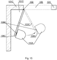
- FIG. 15 An exemplary use of the hook manipulator (117) and a hook (109C) or (109B) is presented in Fig. 15 .
- the device (110A) positions itself so as to connect the hook manipulator (117) to the hook (109C) and pull the door to a desired position.
- the position understood as the point, at which the device (110A) stops pulling the door (103C) may be determined in any of the ways described in the previous embodiments.
- another embodiment may comprise the robot first remember the initial positioning of the door, then move the door as required to achieve best cleaning of the surface and lastly bring back the door to the initial position.
- Fig. 16 presents a general overview of the present method encompassing all of the aforementioned embodiments.
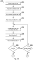
- step (401) there is executed scanning of the vicinity of an autonomous cleaning apparatus by means of at least one sensor.
- step (401) the system detects an unreachable area, being unreachable by the autonomous cleaning apparatus.
- the system detects a door in proximity to the unreachable area and establishes that the unreachable area is unreachable due to the positioning of the door wing.
- the device (110) automatically moves the door wing in order to obtain access to and clean the unreachable area.
- the aforementioned invention allows for more efficient cleaning by autonomous, robotic cleaners. Therefore, the invention provides a useful, concrete and tangible result.
- a tangible device operates to a novel set of instructions, which improve its effectiveness.
- the machine or transformation test is fulfilled and the idea is not abstract.
- the present invention may take the form of an entirely hardware embodiment, an entirely software embodiment (including firmware, resident software, micro-code, etc.) or an embodiment combining software and hardware aspects that may all generally be referred to herein as a "circuit", "module” or "system”.
- the present invention may take the form of a computer program product embodied in any tangible medium of expression having computer usable program code embodied in the medium.
- the aforementioned method for an autonomous cleaning apparatus may be performed and/or controlled by one or more computer programs.
- Such computer programs are typically executed by utilizing the computing resources in a computing device.
- Applications are stored on a non-transitory medium.
- An example of a non-transitory medium is a non-volatile memory, for example a flash memory while an example of a volatile memory is RAM.
- the computer instructions are executed by a processor.
- These memories are exemplary recording media for storing computer programs comprising computer-executable instructions performing all the steps of the computer-implemented method according the technical concept presented herein.
Landscapes
- Engineering & Computer Science (AREA)
- Physics & Mathematics (AREA)
- General Physics & Mathematics (AREA)
- Aviation & Aerospace Engineering (AREA)
- Automation & Control Theory (AREA)
- Remote Sensing (AREA)
- Radar, Positioning & Navigation (AREA)
- Mechanical Engineering (AREA)
- Electromagnetism (AREA)
- Medical Informatics (AREA)
- Game Theory and Decision Science (AREA)
- Evolutionary Computation (AREA)
- Business, Economics & Management (AREA)
- Health & Medical Sciences (AREA)
- Artificial Intelligence (AREA)
- Control Of Position, Course, Altitude, Or Attitude Of Moving Bodies (AREA)
- Manipulator (AREA)
- Electric Vacuum Cleaner (AREA)
Description
- The present invention relates to a system and method for an autonomous cleaning apparatus. In particular, the invention relates mainly to devices moving through surfaces e.g. autonomous vacuum cleaners or mops. Such devices are required to move through available surface in order to reach as much area as possible. The present invention is not limited to such devices as it may apply to any devices required to cover a certain surface area.
- Existing solutions include autonomous systems for corner detection like the publication
US 8,855,914 B1 . However the publication itself lists corners of angles smaller then 90deg as left worse cleaned then those that are exactly or almost exactly 90deg. Since the typical scenario where corners angled less the 90deg are met is open doors, the present invention attempts to allow the surface treatment apparatus to reach a less then 90deg corner more efficiently. - Other solutions in this technical field include
US 6809490 B2 entitled "Method and system for multi-mode coverage for an autonomous robot", which discloses a control system for a mobile robot (10) for effectively covering a given area by operating in a plurality of modes, including an obstacle following mode (51) and a random bounce mode (49). In other embodiments, spot coverage, such as spiralling (45), or other modes are also used to increase effectiveness. In addition, a behaviour based architecture is used to implement the control system, and various escape behaviours are used to ensure full coverage. - Further prior art of
US 20130206177 A1 , discloses an apparatus and method for controlling cleaning in robotic cleaner. An operation of a robotic cleaner includes generating at least one map including information regarding a space to be cleaned by using information measured by at least one sensor. The operation also includes setting a cleaning path by using the at least one map, and cleaning according to the cleaning path. - Lastly,
DE102011050357 discloses a method utilizing an automatic movable apparatus for recording and processing an acoustic signal in an audible region such that the movable apparatus is controlled based on transmission of the acoustic signal. An automatic movable auxiliary device i.e. remote controller, is operated for monitoring and/or activating the movable apparatus. The movable apparatus is operated for recording and processing a light signal such that transmission of the light signal to a cleaning area is controlled. An independent claim is also included for a method for performing cooperation of an automatic movable apparatus with a door. - The invention is defined by the claims.
- An object of the present invention is a method for an autonomous cleaning apparatus, the method comprising the steps of scanning a vicinity of an autonomous cleaning apparatus by means of at least one sensor; detecting an unreachable area, being unreachable by the autonomous cleaning apparatus; detecting a door in proximity to the unreachable area; detecting that the unreachable area is unreachable due to the positioning of the door wing; automatically moving the door wing, by the autonomous cleaning apparatus, in order to obtain access to and clean the unreachable area wherein the step of detecting a door in proximity to the unreachable area comprises measuring the length of each side of the door wing.
- Preferably, the unreachable area is a corner of 90 or less degrees measure. Preferably, the method further comprises determining thickness of the detected door wing.
- Preferably, the method further comprises determining presence of a door gap under the detected door wing.
- Preferably, the step of automatically moving the door wing is effected by a door wing position changing means.
- Preferably, the door wing position changing means allow to push or pull the door wing.
- Preferably, the door wing position changing means is an electromagnet or a suction element or a neodymium magnet or a retractable hook.
- Preferably, the step of detecting a door in proximity to the unreachable area comprises detecting, with a sensor, a tag attached to the door.
- Preferably, the tag is an RFID tag or an optical tag or a magnetic tag.
- Preferably, the tag has an enabled state and a disabled state wherein the enabled state allows the tag to be detected by the sensor and the disabled state disallows the tag from being detected by the sensor.
- Preferably, the method further comprises the steps of remembering the initial positioning of the door; moving the door as required to achieve best cleaning of the surface and lastly bringing back the door to the initial position.
- Another object of the present invention is a computer program comprising program code means for performing all the steps of the computer-implemented method according to the present invention when said program is run on a computer.
- Another object of the present invention is a computer readable medium storing computer-executable instructions performing all the steps of the computer-implemented method according to the present invention when executed on a computer.
- These and other objects of the invention presented herein are accomplished by providing a system and method for an autonomous cleaning apparatus. Further details and features of the present invention, its nature and various advantages will become more apparent from the following detailed description of the preferred embodiments shown in a drawing, in which:
-
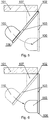
Fig. 1 shows the situation according to the embodiments of the present invention which the present invention handles; -
Fig. 2 depicts a robotic device at a detected corner of less than 90 degrees; -
Fig. 3 shows the said robot after turning at the aforementioned angle and proceeding along the first wall; -
Fig. 4 depicts the path travelled by the robotic device according to the described embodiments of the present invention; -
Fig. 5 depicts the robotic device positioned to push the door; -
Fig. 6 depicts the robotic device having pushed the door to a 90 degree angle; -
Fig. 7A andFig. 7B present the method of classification an obstacle as a door; -
Fig. 8 presents the method of pushing the door to a 90 degree angle; -
Fig. 9 shows another exemplary situation according to the embodiments of the present invention which the present invention handles; -
Fig. 10 shows an exemplary embodiment of an autonomous robotic surface coverage device; -
Fig. 11 presents a situation of an unreachable area; -
Fig. 12 shows an embodiment of the device comprising a hook manipulator; -
Fig. 13 presents another situation of an unreachable area; -
Fig. 14 presents a further situation of an unreachable area; -
Fig. 15 depicts an exemplary use of the hook manipulator; and -
Fig. 16 presents the method according to the present invention. - Some portions of the detailed description which follows are presented in terms of data processing procedures, steps or other symbolic representations of operations on data bits that can be performed on computer memory. Therefore, a computer executes such logical steps thus requiring physical manipulations of physical quantities.
- Usually these quantities take the form of electrical or magnetic signals capable of being stored, transferred, combined, compared, and otherwise manipulated in a computer system. For reasons of common usage, these signals are referred to as bits, packets, messages, values, elements, symbols, characters, terms, numbers, or the like.
- Additionally, all of these and similar terms are to be associated with the appropriate physical quantities and are merely convenient labels applied to these quantities. Terms such as "processing" or "creating" or "transferring" or "executing" or "determining" or "detecting" or "obtaining" or "selecting" or "calculating" or "generating" or the like, refer to the action and processes of a computer system that manipulates and transforms data represented as physical (electronic) quantities within the computer's registers and memories into other data similarly represented as physical quantities within the memories or registers or other such information storage.
- A computer-readable (storage) medium, such as referred to herein, typically may be non-transitory and/or comprise a non-transitory device. In this context, a non-transitory storage medium may include a device that may be tangible, meaning that the device has a concrete physical form, although the device may change its physical state. Thus, for example, non-transitory refers to a device remaining tangible despite a change in state.
- As utilized herein, the term "example" means serving as a non-limiting example, instance, or illustration. As utilized herein, the terms "for example" and "e.g." introduce a list of one or more non-limiting examples, instances, or illustrations.
- As utilized herein, the term "door" means a movable, usually solid, barrier for opening and closing an entranceway, cupboard, cabinet, or the like, commonly turning on hinges or sliding in grooves.
- The invention comprises a method of classification of an obstacle as door, and a method of handling the door in order to eliminate, for example a less then 90deg angle.
- The following description presents a preferred embodiment of the present invention focusing on a robotic vacuum cleaner as a type of surface treatment device. The use of a robotic vacuum is exemplary only and is in no way limiting to the present invention.
- An exemplary embodiment of a robotic surface treatment device is depicted in
Fig. 10 . An exemplary vacuum cleaner is presented. The vacuum cleaner (110) is preferably equipped with a central processing unit performing and coordinating all actions resulting from the present invention. Preferably, a memory (116) is included that may store any operational data or instructions. - The device (110) preferably also comprises a display (111) for interaction with its user. The CPU is able to interact with a plurality of sensors (depicted as (112)), wherein the plurality of sensors comprises distance sensors and/or touch sensors or the like. The device (110) also preferably comprises other elements that may be used to treat the surface, on which the device works.
- An exemplary element is depicted as a brush (114). The brush is preferably placed near the front side of the device, which is a known solution in the current state of the art. The device (110) also contains one or more motors (115) and wheels or other means of movement that allow the device (110) to move in a particular direction.
- Beginning with
Fig. 1 , a preferred situation where the present invention may be applied is depicted. The robot (110) approaches an object (preferably a door) (103) while proceeding along a wall (101). - The door (103) is attached to a wall (101) with one or more hinges (102) and can rotate about an axis of that one or more hinges. The door (103) can close to seal or partially seal the opening gap (105). The gap (105) can be a passage-way, a door-way, a wardrobe or the like. It is apparent, in the depicted situation, that the robot is not able to reach area (107) due to its size.
- The method (200) according to the present embodiment of the present invention is further depicted in
Fig. 7A andFig. 7B . The method starts at step (201) with a detection of a corner of 90 or less degrees measure. This situation is depicted inFig. 2 . It is to be noted that neither the method of detection of corners nor the method of determining the measure of a corner are within the scope of the present invention. The behaviour of the robot resulting from such detection is. - The robot approaches the detected corner at step (202) and proceeds with an adequate turn at step (203). It is apparent to a one skilled in the art that the turn may be performed according to any known or implemented methods without departing from the idea of the present invention.
- At this point the robot resets a value of D1 to zero (204) wherein D1 denotes a distance travelled by the robot. At step (205) the robot proceeds along the wall after turning. This situation is depicted in
Fig. 3 . - The direction R1 of this movement is measured at step (206) and distance D1 at step (207). At step (208) a sensor interaction takes place and it is decided whether the interaction is an end of a wall. If not, then at step (209), it is decided whether the interaction changes the direction of movement of the robot.
- It is apparent to a one skilled in the art that this may be due to involvement of many sensors in the interaction at step (208). Hence, the behaviour resulting from such may comprise change in direction. This is decided at step (209). If the direction is not changed, the robot proceeds along the wall at step (205). However, if the direction changes, then the obstacle (103) is not considered a door and the method ends at step (219).
- If the wall ends at step (208), then the robot proceeds with an adequate turn at step (210). The turn may be realized according to publication
US 8,855,914 B1 (page 5, line 54). However the method of realizing the turn is not in the scope of the present invention and is not limiting in any way. - The area where the turn takes place is shown in
Fig. 4 , item (104). Next, the distance value D1 is reset to zero at step (211) and the robot proceeds along the new wall at step (212). This area is depicted inFig. 4 , item (108). The direction of the movement is recorded at step (213) and the distance D2 at step (214). At step (215) a sensor interaction takes place and it is decided whether the interaction is an end of wall or the interaction changes the direction of movement of the robot. It is apparent to a one skilled in the art that this may be due to involvement of many sensors in the interaction at step (215). Hence, the behavior resulting from such may comprise change in direction. If the direction is not changed and a wall end was not detected, the robot proceeds along the wall at step (212). - If the wall ends at step (215) or the direction changes at step (215), then the robot determines the parameters of the travelled path. The path is depicted in
Fig. 4 . It is decided whether the distance D2 travelled along the second wall is large enough in comparison to the distance D1. An exemplary comparison checks whether D2 is larger than a predefined fraction of D1. - Preferably the distance between vectors V1 and V2 is also measured in order to determine object thickness. The vector V1 begins at the point of start of D1 measurement at step (204) and ends at the last point of measuring of D1 at step (207). The vector V2 begins at the point of start of V2 measurement at step (211) and ends at the last point of measuring of D2 at step (214). Preferably, it is checked whether the distance between vector V1 and V2 is small enough (taking into account the outer dimensions of the robot) to determine that object (103) is a door. An exemplary embodiment of such check would comprise a comparison of the distance between V1 and V2 to a predefined value m of 10cm.
- In another embodiment, a further door gap sensor may be added to the device (110) such that the sensor may detect presence of a door gap under the detected object, preliminarily identified as door.
- At step (217) it is also checked whether the measured direction R2 is opposite or substantially opposite to R1. It is apparent to a one skilled in the art that the same purpose of measuring the travelling path may be achieved by measuring different parameters adequately to the capabilities of the robotic device which is not limiting to the present invention in any way.
- If the comparison at step (217) is positive, the obstacle (103) is considered a door (218) and the robot may choose to handle the obstacle (103) preferably according to method (300) in
Fig, 8 . However, if the comparison is negative, the obstacle (103) is not considered a door, the method ends at step (219). - The method of
Fig. 8 (300) begins at step (301), where the robot takes a position near the last measurement of distance D1. It is apparent to a one skilled in the art that the determination of this location may be done differently and the method described here is merely a preferred embodiment. The purpose is to position the device (110) adequately towards the ending (106) of the door (103) (the ending being positioned furthest from the hinges). The exact placement may be dependent on the physical characteristics and capabilities of the robot and/or on external conditions or the like. - The method of reaching the location near the aforementioned end (106) of the door (103) is also not in the scope of the present invention. It may be retracing of the path of the robot or an algorithm based on starting and ending location only or remembering past interactions with sensors to optimize the path or the like. At step (302), the robot preferably faces the door i.e. it positions itself so as to be able to move directly towards it.
- At step (303) the robot approaches and touches the door in order to push it at step (304). Thus it may be defined, that the robot (110) comprises a door wing position changing means, being in that case its motor and wheels allowing it to push the door wing. The robot according to step (303) is depicted in
Fig. 5 , while the robot according to step (304) is depicted inFig. 6 . - The push is done so as to position the door, preferably at a 90 degrees angle towards the wall (101). It is apparent to a one skilled in the art that the parameters of the push may vary and will most likely be subject to either physical characteristics or capabilities of the robot or to actual conditions or the like. For example, the robot may push the door with a minimal force so as to be able to detect resistance and stop the method (300) in order to avoid damage to itself or the door.
- It is also preferred that the robot is configured to push the door as slowly as possible so as to allow the door to stop at 90 degree angle rather than keep moving after the robot stops pushing.
- In other embodiment, the robot may first remember the initial positioning of the door, then move the door as required to achieve best cleaning of the surface and lastly bring back the door to the initial position.
- The distance the robot needs to travel, in order to push the door (103) to a 90 degree angle towards the wall (101), can be computed or determined during the time of the push. An exemplary embodiment of the push would determine to push the door for a distance computed based on the measured angle of the corner detected at step (201).
- Finally the robot may proceed to cleaning the area (107). This may be implemented according to publication
US 8,855,914 B1 already mentioned earlier. - The change of proceeding of the robot (110), along its path to handling the door (103) according to method (300), may be implemented according to publication
US 6,809,490 B2 (paragraph at p 8, line 48). However, this is not limiting to the present invention in any way. - It also apparent, to one skilled in the art, that the terms 90 degree and less than 90 degree when applied to angles or measures of angles are exemplary only and can be modified to match either the physical capabilities of the robot or external conditions or the like. For example, the measures may be modified when applied to an embodiment according to
Fig. 9 . -
Fig 9 shows an exemplary preferred embodiment of the present invention where the 90 degree angle and less than 90 degree angle may be modified to match external conditions. The device (110), detects a corner near a wall (101A) and a door (103A). Alternatively to detecting a corner, the device (110) may detect an unreachable area, which is typically unreachable due to external size of the device (110). - The unreachable area is marked (107A) in
Fig. 9 . All elements are analogous to their counterparts inFig. 1 . However, a one skilled in the art will notice that some of the parameters of the previously described embodiments may be modified in order to make the present invention more useful, e.g. the term 90 degree angle can be changed or otherwise it may come to a situation that the device (110) closes the door (103A) and cannot cross the area (105). - An exemplary embodiment of this change would comprise checking for the closest object after making the turn at area (104) (
Fig. 4 ) and adjust the actual angle, at which to stop the door (according to step (304) of method (300) inFig. 8 ) so that the device (110) can fit between the door (103A) and the detected object. Typically, this object will turn out to be a wall (101). Also the parameter 'k' of step (217) of method (200) (Fig. 7B ) may be modified in such situation. An exemplary embodiment would comprise making the parameter 'k' linearly proportional the measure of the angle of the detected corner. - In another embodiment of the present invention, the device (110) may be able to record its path permanently or at selected periods and/or record the manoeuvres made like turning, pivoting or going straight or the like. Using this information, it is possible to detect that the device (110) is in a situation of an unreachable area presented in
Fig. 11 (107D). - This may be achieved by analysis of the parameters analogously to step (217) of method (200). However, in this embodiment the method does not begin with detection of the less than 90 degree angle but rather the detection of this angle finalises the determination that object (103) is a door. All markings in
Fig. 11 are made according to previously describedFig. 1 . - In another aspect of the present invention, the robotic device (110) can be extended with a hook manipulator preferably placed near the front of the device (110A) as presented in
Fig. 12 . The device (110A) inFig. 12 is marked according to marking inFig. 10 . - The hook manipulator (117) can be an electromagnet or a suction element or a neodymium magnet or any retractable form thereof or the like. This hook manipulator has a corresponding hook element that can be attached to objects like doors. The hook manipulator can be used by the device (110A) to attach to a hook in order to push or pull objects like doors. Thus it may be defined, that the robot (110) of this example comprises a different door wing position changing means, being in this case a hook element or a suction element.
- A hook corresponding to an electromagnet hook manipulator or a neodymium hook manipulator may be a metal slate, while a hook corresponding to a suction hook manipulator may be a flat sticker or may be omitted entirely enabling hooking directly to the surface of the object.
- The purpose of the modification according to
Fig. 12 are to allow the device (110A) to handle situations presented inFig. 13 and Fig. 14 where it is not possible to push the door (103B) and (103C). Further, the hook manipulator (117) increases the precision of door movement in comparison to the push method. - In a further aspect of the present invention, the object (103B) and (103C) may further be equipped with a tag. The device (110A) is equipped with a sensor that is able to detect a tag when traveling along an obstacle e.g. a wall or door. The sensor may be placed as depicted by item (112) and may be the same sensor or a separate sensor or placed anywhere else on the device (110A). The tag may be an RFID tag or an optical tag (mirror or image) or a magnetic tag or the like.
- Preferably, the tag has an enabled state and a disabled state wherein the enabled state allows the tag to be detected by the sensor and the disabled state disallows the tag from being detected by the sensor. The tag can be affixed to an obstacle, preferably a door, in a way allowing for the aforementioned detection, preferably when the tag is in an enabled state and disallowing the aforementioned detection preferably when the tag is in a disabled state.
- The device (110A) may determine with the utmost certainty that the object (103B) and (103C) is a door if the aforementioned tag is detected. Then the method (200) or a modified method (200) may be stopped and adequate behavior may be enacted. It is apparent to a one skilled in the art that a similar method may be applied to the situation according to
Fig. 1 . Also the tag may be a separate object or device than the hook or can be merged into one or (in some embodiments) can be the same object or device or the like. - Exemplary embodiment of the method of using the hook manipulator and a hook are presented in
Fig. 13 and Fig. 14 . The hooks (109B) and (109C) may be attached to doors (103B) or (103C) respectively, preferably near the ends (106B) and (106C) respectively. - The device (110A) is able to detect the situations presented in
Fig. 13 and Fig. 14 and recognize areas (107B) and (107C) as less than 90 degree angles. The angles' measure may in fact be greater than 90 degrees. It is however beneficial to keeping the unity of the method (200) to understand the corners at areas (107B) and (107C) as less than 90 degree corners in any case. - An exemplary use of the hook manipulator (117) and a hook (109C) or (109B) is presented in
Fig. 15 . The device (110A) positions itself so as to connect the hook manipulator (117) to the hook (109C) and pull the door to a desired position. The position understood as the point, at which the device (110A) stops pulling the door (103C), may be determined in any of the ways described in the previous embodiments. - Similarly to the previously described embodiments, also according to the present invention another embodiment may comprise the robot first remember the initial positioning of the door, then move the door as required to achieve best cleaning of the surface and lastly bring back the door to the initial position.
-
Fig. 16 presents a general overview of the present method encompassing all of the aforementioned embodiments. At step (401), there is executed scanning of the vicinity of an autonomous cleaning apparatus by means of at least one sensor. Next (402), the system detects an unreachable area, being unreachable by the autonomous cleaning apparatus. Subsequently (403) the system detects a door in proximity to the unreachable area and establishes that the unreachable area is unreachable due to the positioning of the door wing. Next (404) the device (110) automatically moves the door wing in order to obtain access to and clean the unreachable area. - From the foregoing descriptions of the various embodiments of the present invention it can be appreciated that even though the invention does not guarantee the detection of every possible unreachable area by the autonomous cleaning apparatus, the methods according to the present invention allow to substantially increase the accuracy of surface coverage in at least the presented situations.
- The aforementioned invention allows for more efficient cleaning by autonomous, robotic cleaners. Therefore, the invention provides a useful, concrete and tangible result.
- According to the claimed method, a tangible device operates to a novel set of instructions, which improve its effectiveness. Thus, the machine or transformation test is fulfilled and the idea is not abstract.
- At least parts of the methods according to the invention may be computer implemented. Accordingly, the present invention may take the form of an entirely hardware embodiment, an entirely software embodiment (including firmware, resident software, micro-code, etc.) or an embodiment combining software and hardware aspects that may all generally be referred to herein as a "circuit", "module" or "system".
- Furthermore, the present invention may take the form of a computer program product embodied in any tangible medium of expression having computer usable program code embodied in the medium.
- It can be easily recognized, by one skilled in the art, that the aforementioned method for an autonomous cleaning apparatus may be performed and/or controlled by one or more computer programs. Such computer programs are typically executed by utilizing the computing resources in a computing device. Applications are stored on a non-transitory medium. An example of a non-transitory medium is a non-volatile memory, for example a flash memory while an example of a volatile memory is RAM. The computer instructions are executed by a processor. These memories are exemplary recording media for storing computer programs comprising computer-executable instructions performing all the steps of the computer-implemented method according the technical concept presented herein.
- While the invention presented herein has been depicted, described, and has been defined with reference to particular preferred embodiments, such references and examples of implementation in the foregoing specification do not imply any limitation on the invention. It will, however, be evident that various modifications and changes may be made thereto without departing from the broader scope of the technical concept. The presented preferred embodiments are exemplary only, and are not exhaustive of the scope of the technical concept presented herein.
- Accordingly, the scope of protection is not limited to the preferred embodiments described in the specification, but is only limited by the claims that follow.
Claims (14)
- Method for an autonomous cleaning apparatus, the method comprising the steps of:• scanning (401) a vicinity of an autonomous cleaning apparatus by means of at least one sensor; the method being characterized in that it further comprises the steps of:• detecting an unreachable area (402), being unreachable by the autonomous cleaning apparatus;• detecting a door (403) in proximity to the unreachable area (107);• detecting (404) that the unreachable area is unreachable due to the positioning of the door wing;• automatically moving (405) the door wing, by the autonomous cleaning apparatus, in order to obtain access to and clean the unreachable area the method being characterized in that• the step of detecting a door (403) in proximity to the unreachable area (107) comprises measuring the length (D1, D2, 217) of each side of the door wing.
- The method according to claim 1 characterized in that the unreachable area (107) is a corner of 90 or less degrees measure.
- The method according to claim 1 characterized in that it further comprises determining thickness of the detected door wing.
- The method according to claim 1 characterized in that it further comprises determining presence of a door gap under the detected door wing.
- The method according to claim 1 characterized in that the step of automatically moving (405) the door wing is effected by a door wing position changing means.
- The method according to claim 5 characterized in that the door wing position changing means allow to push or pull the door wing.
- The method according to claim 6 characterized in that the door wing position changing means is an electromagnet or a suction element or a neodymium magnet or a retractable hook.
- The method according to claim 1 characterized in that the step of detecting a door (403) in proximity to the unreachable area (107) comprises detecting, with a sensor, a tag attached to the door.
- The method according to claim 8 characterized in that the tag is an RFID tag or an optical tag or a magnetic tag.
- The method according to claim 9 characterized in that the tag has an enabled state and a disabled state wherein the enabled state allows the tag to be detected by the sensor and the disabled state disallows the tag from being detected by the sensor.
- The method according to claim 1 characterized in that it further comprises the steps of remembering the initial positioning of the door; moving the door as required to achieve best cleaning of the surface and lastly bringing back the door to the initial position.
- A computer program comprising program code means for performing all the steps of the computer-implemented method according to claim 1 when said program is run on a computer.
- A computer readable medium storing computer-executable instructions performing all the steps of the computer-implemented method according to claim 1 when executed on a computer.
- System for an autonomous cleaning apparatus the system being characterized in that it comprises means configured to execute all steps of the method according to claim 1; and further comprises a door wing position changing means.
Priority Applications (2)
| Application Number | Priority Date | Filing Date | Title |
|---|---|---|---|
| EP16161810.3A EP3223099B1 (en) | 2016-03-23 | 2016-03-23 | System and method for an autonomous cleaning apparatus |
| US15/464,371 US10335003B2 (en) | 2016-03-23 | 2017-03-21 | System and method for an autonomous cleaning apparatus |
Applications Claiming Priority (1)
| Application Number | Priority Date | Filing Date | Title |
|---|---|---|---|
| EP16161810.3A EP3223099B1 (en) | 2016-03-23 | 2016-03-23 | System and method for an autonomous cleaning apparatus |
Publications (2)
| Publication Number | Publication Date |
|---|---|
| EP3223099A1 EP3223099A1 (en) | 2017-09-27 |
| EP3223099B1 true EP3223099B1 (en) | 2021-09-15 |
Family
ID=55640565
Family Applications (1)
| Application Number | Title | Priority Date | Filing Date |
|---|---|---|---|
| EP16161810.3A Active EP3223099B1 (en) | 2016-03-23 | 2016-03-23 | System and method for an autonomous cleaning apparatus |
Country Status (2)
| Country | Link |
|---|---|
| US (1) | US10335003B2 (en) |
| EP (1) | EP3223099B1 (en) |
Families Citing this family (5)
| Publication number | Priority date | Publication date | Assignee | Title |
|---|---|---|---|---|
| JP2019170668A (en) * | 2018-03-28 | 2019-10-10 | 株式会社日立製作所 | Autonomous travel type vacuum cleaner and door |
| CN109032148B (en) * | 2018-09-25 | 2021-05-18 | 广东宝乐机器人股份有限公司 | Wall corner identification method and device, terminal equipment and storage medium |
| KR20200084449A (en) * | 2018-12-26 | 2020-07-13 | 삼성전자주식회사 | Cleaning robot and Method of performing task thereof |
| CN110811447B (en) * | 2019-10-21 | 2022-04-08 | 英华达(南京)科技有限公司 | Cleaning method, cleaning robot, and computer-readable storage medium |
| CN115190773A (en) * | 2019-12-23 | 2022-10-14 | 伊莱克斯公司 | Moving object of robot cleaning device |
Family Cites Families (7)
| Publication number | Priority date | Publication date | Assignee | Title |
|---|---|---|---|---|
| EP2998816B1 (en) | 2001-06-12 | 2018-12-05 | iRobot Corporation | Multi-code coverage for an autonomous robot |
| IL145680A0 (en) * | 2001-09-26 | 2002-06-30 | Friendly Robotics Ltd | Robotic vacuum cleaner |
| DE102011050357A1 (en) * | 2010-08-12 | 2012-02-16 | Vorwerk & Co. Interholding Gmbh | Method for controlling i.e. guiding, movable household floor cleaning device e.g. sucking robot, involves recording and processing light signal such that transmission of light signal to cleaning area is controlled |
| KR101984214B1 (en) * | 2012-02-09 | 2019-05-30 | 삼성전자주식회사 | Apparatus and method for controlling cleaning in rototic cleaner |
| US8855914B1 (en) | 2012-08-31 | 2014-10-07 | Neato Robotics, Inc. | Method and apparatus for traversing corners of a floored area with a robotic surface treatment apparatus |
| WO2014066690A2 (en) * | 2012-10-24 | 2014-05-01 | Robotex Inc. | Infrastructure for robots in human-centric environments |
| DE102015121666B3 (en) * | 2015-12-11 | 2017-05-24 | RobArt GmbH | Remote control of a mobile, autonomous robot |
-
2016
- 2016-03-23 EP EP16161810.3A patent/EP3223099B1/en active Active
-
2017
- 2017-03-21 US US15/464,371 patent/US10335003B2/en active Active
Also Published As
| Publication number | Publication date |
|---|---|
| US10335003B2 (en) | 2019-07-02 |
| EP3223099A1 (en) | 2017-09-27 |
| US20170273530A1 (en) | 2017-09-28 |
Similar Documents
| Publication | Publication Date | Title |
|---|---|---|
| US10335003B2 (en) | System and method for an autonomous cleaning apparatus | |
| US10328578B2 (en) | Methods and systems for detecting, recognizing, and localizing pallets | |
| US20130218342A1 (en) | Control method for cleaning robots | |
| US9694499B2 (en) | Article pickup apparatus for picking up randomly piled articles | |
| CN111164529B (en) | Environment information updating device, environment information updating method, and program | |
| US8600603B2 (en) | Apparatus and method of localization of mobile robot | |
| JP2021054660A5 (en) | ||
| WO2018124682A3 (en) | Mobile robot and control method therefor | |
| CN108214487B (en) | Robot target positioning and grabbing method based on binocular vision and laser radar | |
| US9434074B2 (en) | Autonomous running control method and device of autonomous running apparatus, and program for autonomous running control device | |
| US9081384B2 (en) | Autonomous electronic apparatus and navigation method thereof | |
| US20160334802A1 (en) | Robot and control method thereof | |
| JP2014174747A5 (en) | ||
| EP3611589B1 (en) | Method for controlling motion of robot based on map prediction | |
| KR101202108B1 (en) | Localizing method for mobile robot | |
| US20140022528A1 (en) | Proximity sensor and proximity sensing method using light quantity of reflection light | |
| CN111216122B (en) | Gripping robot and control program for gripping robot | |
| JP2014203144A (en) | Autonomous mobile apparatus | |
| US11141866B2 (en) | Grasping apparatus, grasping determination method and grasping determination program | |
| KR20100045585A (en) | Method for detecting position of robot | |
| JP2019093152A5 (en) | ||
| JP6410173B2 (en) | Door open / close robot, door open / close robot control system | |
| JP6459964B2 (en) | Information processing system, information processing method, and program | |
| CN109635691A (en) | A kind of control method, device, equipment and storage medium | |
| WO2016009585A1 (en) | Autonomous mobile object and method of controlling same |
Legal Events
| Date | Code | Title | Description |
|---|---|---|---|
| PUAI | Public reference made under article 153(3) epc to a published international application that has entered the european phase |
Free format text: ORIGINAL CODE: 0009012 |
|
| STAA | Information on the status of an ep patent application or granted ep patent |
Free format text: STATUS: THE APPLICATION HAS BEEN PUBLISHED |
|
| AK | Designated contracting states |
Kind code of ref document: A1 Designated state(s): AL AT BE BG CH CY CZ DE DK EE ES FI FR GB GR HR HU IE IS IT LI LT LU LV MC MK MT NL NO PL PT RO RS SE SI SK SM TR |
|
| AX | Request for extension of the european patent |
Extension state: BA ME |
|
| STAA | Information on the status of an ep patent application or granted ep patent |
Free format text: STATUS: REQUEST FOR EXAMINATION WAS MADE |
|
| 17P | Request for examination filed |
Effective date: 20180309 |
|
| RBV | Designated contracting states (corrected) |
Designated state(s): AL AT BE BG CH CY CZ DE DK EE ES FI FR GB GR HR HU IE IS IT LI LT LU LV MC MK MT NL NO PL PT RO RS SE SI SK SM TR |
|
| STAA | Information on the status of an ep patent application or granted ep patent |
Free format text: STATUS: EXAMINATION IS IN PROGRESS |
|
| 17Q | First examination report despatched |
Effective date: 20200907 |
|
| STAA | Information on the status of an ep patent application or granted ep patent |
Free format text: STATUS: EXAMINATION IS IN PROGRESS |
|
| GRAP | Despatch of communication of intention to grant a patent |
Free format text: ORIGINAL CODE: EPIDOSNIGR1 |
|
| STAA | Information on the status of an ep patent application or granted ep patent |
Free format text: STATUS: GRANT OF PATENT IS INTENDED |
|
| INTG | Intention to grant announced |
Effective date: 20210504 |
|
| RAP3 | Party data changed (applicant data changed or rights of an application transferred) |
Owner name: ADVANCED DIGITAL BROADCAST S.A. |
|
| GRAS | Grant fee paid |
Free format text: ORIGINAL CODE: EPIDOSNIGR3 |
|
| GRAA | (expected) grant |
Free format text: ORIGINAL CODE: 0009210 |
|
| STAA | Information on the status of an ep patent application or granted ep patent |
Free format text: STATUS: THE PATENT HAS BEEN GRANTED |
|
| AK | Designated contracting states |
Kind code of ref document: B1 Designated state(s): AL AT BE BG CH CY CZ DE DK EE ES FI FR GB GR HR HU IE IS IT LI LT LU LV MC MK MT NL NO PL PT RO RS SE SI SK SM TR |
|
| REG | Reference to a national code |
Ref country code: GB Ref legal event code: FG4D Ref country code: CH Ref legal event code: EP |
|
| REG | Reference to a national code |
Ref country code: DE Ref legal event code: R096 Ref document number: 602016063650 Country of ref document: DE |
|
| REG | Reference to a national code |
Ref country code: IE Ref legal event code: FG4D |
|
| REG | Reference to a national code |
Ref country code: AT Ref legal event code: REF Ref document number: 1430976 Country of ref document: AT Kind code of ref document: T Effective date: 20211015 |
|
| REG | Reference to a national code |
Ref country code: LT Ref legal event code: MG9D |
|
| REG | Reference to a national code |
Ref country code: NL Ref legal event code: MP Effective date: 20210915 |
|
| PG25 | Lapsed in a contracting state [announced via postgrant information from national office to epo] |
Ref country code: FI Free format text: LAPSE BECAUSE OF FAILURE TO SUBMIT A TRANSLATION OF THE DESCRIPTION OR TO PAY THE FEE WITHIN THE PRESCRIBED TIME-LIMIT Effective date: 20210915 Ref country code: NO Free format text: LAPSE BECAUSE OF FAILURE TO SUBMIT A TRANSLATION OF THE DESCRIPTION OR TO PAY THE FEE WITHIN THE PRESCRIBED TIME-LIMIT Effective date: 20211215 Ref country code: BG Free format text: LAPSE BECAUSE OF FAILURE TO SUBMIT A TRANSLATION OF THE DESCRIPTION OR TO PAY THE FEE WITHIN THE PRESCRIBED TIME-LIMIT Effective date: 20211215 Ref country code: LT Free format text: LAPSE BECAUSE OF FAILURE TO SUBMIT A TRANSLATION OF THE DESCRIPTION OR TO PAY THE FEE WITHIN THE PRESCRIBED TIME-LIMIT Effective date: 20210915 Ref country code: SE Free format text: LAPSE BECAUSE OF FAILURE TO SUBMIT A TRANSLATION OF THE DESCRIPTION OR TO PAY THE FEE WITHIN THE PRESCRIBED TIME-LIMIT Effective date: 20210915 Ref country code: RS Free format text: LAPSE BECAUSE OF FAILURE TO SUBMIT A TRANSLATION OF THE DESCRIPTION OR TO PAY THE FEE WITHIN THE PRESCRIBED TIME-LIMIT Effective date: 20210915 Ref country code: HR Free format text: LAPSE BECAUSE OF FAILURE TO SUBMIT A TRANSLATION OF THE DESCRIPTION OR TO PAY THE FEE WITHIN THE PRESCRIBED TIME-LIMIT Effective date: 20210915 |
|
| REG | Reference to a national code |
Ref country code: AT Ref legal event code: MK05 Ref document number: 1430976 Country of ref document: AT Kind code of ref document: T Effective date: 20210915 |
|
| PG25 | Lapsed in a contracting state [announced via postgrant information from national office to epo] |
Ref country code: LV Free format text: LAPSE BECAUSE OF FAILURE TO SUBMIT A TRANSLATION OF THE DESCRIPTION OR TO PAY THE FEE WITHIN THE PRESCRIBED TIME-LIMIT Effective date: 20210915 Ref country code: GR Free format text: LAPSE BECAUSE OF FAILURE TO SUBMIT A TRANSLATION OF THE DESCRIPTION OR TO PAY THE FEE WITHIN THE PRESCRIBED TIME-LIMIT Effective date: 20211216 |
|
| PG25 | Lapsed in a contracting state [announced via postgrant information from national office to epo] |
Ref country code: AT Free format text: LAPSE BECAUSE OF FAILURE TO SUBMIT A TRANSLATION OF THE DESCRIPTION OR TO PAY THE FEE WITHIN THE PRESCRIBED TIME-LIMIT Effective date: 20210915 |
|
| PG25 | Lapsed in a contracting state [announced via postgrant information from national office to epo] |
Ref country code: IS Free format text: LAPSE BECAUSE OF FAILURE TO SUBMIT A TRANSLATION OF THE DESCRIPTION OR TO PAY THE FEE WITHIN THE PRESCRIBED TIME-LIMIT Effective date: 20220115 Ref country code: SM Free format text: LAPSE BECAUSE OF FAILURE TO SUBMIT A TRANSLATION OF THE DESCRIPTION OR TO PAY THE FEE WITHIN THE PRESCRIBED TIME-LIMIT Effective date: 20210915 Ref country code: SK Free format text: LAPSE BECAUSE OF FAILURE TO SUBMIT A TRANSLATION OF THE DESCRIPTION OR TO PAY THE FEE WITHIN THE PRESCRIBED TIME-LIMIT Effective date: 20210915 Ref country code: RO Free format text: LAPSE BECAUSE OF FAILURE TO SUBMIT A TRANSLATION OF THE DESCRIPTION OR TO PAY THE FEE WITHIN THE PRESCRIBED TIME-LIMIT Effective date: 20210915 Ref country code: PT Free format text: LAPSE BECAUSE OF FAILURE TO SUBMIT A TRANSLATION OF THE DESCRIPTION OR TO PAY THE FEE WITHIN THE PRESCRIBED TIME-LIMIT Effective date: 20220117 Ref country code: PL Free format text: LAPSE BECAUSE OF FAILURE TO SUBMIT A TRANSLATION OF THE DESCRIPTION OR TO PAY THE FEE WITHIN THE PRESCRIBED TIME-LIMIT Effective date: 20210915 Ref country code: NL Free format text: LAPSE BECAUSE OF FAILURE TO SUBMIT A TRANSLATION OF THE DESCRIPTION OR TO PAY THE FEE WITHIN THE PRESCRIBED TIME-LIMIT Effective date: 20210915 Ref country code: ES Free format text: LAPSE BECAUSE OF FAILURE TO SUBMIT A TRANSLATION OF THE DESCRIPTION OR TO PAY THE FEE WITHIN THE PRESCRIBED TIME-LIMIT Effective date: 20210915 Ref country code: EE Free format text: LAPSE BECAUSE OF FAILURE TO SUBMIT A TRANSLATION OF THE DESCRIPTION OR TO PAY THE FEE WITHIN THE PRESCRIBED TIME-LIMIT Effective date: 20210915 Ref country code: CZ Free format text: LAPSE BECAUSE OF FAILURE TO SUBMIT A TRANSLATION OF THE DESCRIPTION OR TO PAY THE FEE WITHIN THE PRESCRIBED TIME-LIMIT Effective date: 20210915 Ref country code: AL Free format text: LAPSE BECAUSE OF FAILURE TO SUBMIT A TRANSLATION OF THE DESCRIPTION OR TO PAY THE FEE WITHIN THE PRESCRIBED TIME-LIMIT Effective date: 20210915 |
|
| REG | Reference to a national code |
Ref country code: DE Ref legal event code: R097 Ref document number: 602016063650 Country of ref document: DE |
|
| PLBE | No opposition filed within time limit |
Free format text: ORIGINAL CODE: 0009261 |
|
| STAA | Information on the status of an ep patent application or granted ep patent |
Free format text: STATUS: NO OPPOSITION FILED WITHIN TIME LIMIT |
|
| PG25 | Lapsed in a contracting state [announced via postgrant information from national office to epo] |
Ref country code: DK Free format text: LAPSE BECAUSE OF FAILURE TO SUBMIT A TRANSLATION OF THE DESCRIPTION OR TO PAY THE FEE WITHIN THE PRESCRIBED TIME-LIMIT Effective date: 20210915 |
|
| 26N | No opposition filed |
Effective date: 20220616 |
|
| PG25 | Lapsed in a contracting state [announced via postgrant information from national office to epo] |
Ref country code: SI Free format text: LAPSE BECAUSE OF FAILURE TO SUBMIT A TRANSLATION OF THE DESCRIPTION OR TO PAY THE FEE WITHIN THE PRESCRIBED TIME-LIMIT Effective date: 20210915 |
|
| PG25 | Lapsed in a contracting state [announced via postgrant information from national office to epo] |
Ref country code: MC Free format text: LAPSE BECAUSE OF FAILURE TO SUBMIT A TRANSLATION OF THE DESCRIPTION OR TO PAY THE FEE WITHIN THE PRESCRIBED TIME-LIMIT Effective date: 20210915 |
|
| REG | Reference to a national code |
Ref country code: CH Ref legal event code: PL |
|
| REG | Reference to a national code |
Ref country code: BE Ref legal event code: MM Effective date: 20220331 |
|
| PG25 | Lapsed in a contracting state [announced via postgrant information from national office to epo] |
Ref country code: LU Free format text: LAPSE BECAUSE OF NON-PAYMENT OF DUE FEES Effective date: 20220323 Ref country code: LI Free format text: LAPSE BECAUSE OF NON-PAYMENT OF DUE FEES Effective date: 20220331 Ref country code: IT Free format text: LAPSE BECAUSE OF FAILURE TO SUBMIT A TRANSLATION OF THE DESCRIPTION OR TO PAY THE FEE WITHIN THE PRESCRIBED TIME-LIMIT Effective date: 20210915 Ref country code: IE Free format text: LAPSE BECAUSE OF NON-PAYMENT OF DUE FEES Effective date: 20220323 Ref country code: CH Free format text: LAPSE BECAUSE OF NON-PAYMENT OF DUE FEES Effective date: 20220331 |
|
| PG25 | Lapsed in a contracting state [announced via postgrant information from national office to epo] |
Ref country code: BE Free format text: LAPSE BECAUSE OF NON-PAYMENT OF DUE FEES Effective date: 20220331 |
|
| PGFP | Annual fee paid to national office [announced via postgrant information from national office to epo] |
Ref country code: FR Payment date: 20230327 Year of fee payment: 8 |
|
| REG | Reference to a national code |
Ref country code: DE Ref legal event code: R079 Ref document number: 602016063650 Country of ref document: DE Free format text: PREVIOUS MAIN CLASS: G05D0001020000 Ipc: G05D0001430000 |
|
| PG25 | Lapsed in a contracting state [announced via postgrant information from national office to epo] |
Ref country code: HU Free format text: LAPSE BECAUSE OF FAILURE TO SUBMIT A TRANSLATION OF THE DESCRIPTION OR TO PAY THE FEE WITHIN THE PRESCRIBED TIME-LIMIT; INVALID AB INITIO Effective date: 20160323 |
|
| PG25 | Lapsed in a contracting state [announced via postgrant information from national office to epo] |
Ref country code: MK Free format text: LAPSE BECAUSE OF FAILURE TO SUBMIT A TRANSLATION OF THE DESCRIPTION OR TO PAY THE FEE WITHIN THE PRESCRIBED TIME-LIMIT Effective date: 20210915 Ref country code: CY Free format text: LAPSE BECAUSE OF FAILURE TO SUBMIT A TRANSLATION OF THE DESCRIPTION OR TO PAY THE FEE WITHIN THE PRESCRIBED TIME-LIMIT Effective date: 20210915 |
|
| PGFP | Annual fee paid to national office [announced via postgrant information from national office to epo] |
Ref country code: DE Payment date: 20240327 Year of fee payment: 9 Ref country code: GB Payment date: 20240327 Year of fee payment: 9 |