EP3220724B1 - Illumination device and control method therefor, and control system - Google Patents
Illumination device and control method therefor, and control system Download PDFInfo
- Publication number
- EP3220724B1 EP3220724B1 EP16806802.1A EP16806802A EP3220724B1 EP 3220724 B1 EP3220724 B1 EP 3220724B1 EP 16806802 A EP16806802 A EP 16806802A EP 3220724 B1 EP3220724 B1 EP 3220724B1
- Authority
- EP
- European Patent Office
- Prior art keywords
- color
- light
- initial
- reflected light
- illuminating device
- Prior art date
- Legal status (The legal status is an assumption and is not a legal conclusion. Google has not performed a legal analysis and makes no representation as to the accuracy of the status listed.)
- Active
Links
- 238000000034 method Methods 0.000 title claims description 36
- 238000005286 illumination Methods 0.000 title claims description 7
- 230000001678 irradiating effect Effects 0.000 claims description 150
- 238000001514 detection method Methods 0.000 claims description 107
- 239000003086 colorant Substances 0.000 description 46
- 230000003287 optical effect Effects 0.000 description 23
- BWWVXHRLMPBDCK-UHFFFAOYSA-N 1,2,4-trichloro-5-(2,6-dichlorophenyl)benzene Chemical compound C1=C(Cl)C(Cl)=CC(Cl)=C1C1=C(Cl)C=CC=C1Cl BWWVXHRLMPBDCK-UHFFFAOYSA-N 0.000 description 22
- 239000012535 impurity Substances 0.000 description 8
- 238000010586 diagram Methods 0.000 description 7
- 238000005516 engineering process Methods 0.000 description 6
- WUPHOULIZUERAE-UHFFFAOYSA-N 3-(oxolan-2-yl)propanoic acid Chemical compound OC(=O)CCC1CCCO1 WUPHOULIZUERAE-UHFFFAOYSA-N 0.000 description 5
- 229910052980 cadmium sulfide Inorganic materials 0.000 description 5
- 230000006870 function Effects 0.000 description 5
- 230000001795 light effect Effects 0.000 description 5
- 230000001965 increasing effect Effects 0.000 description 4
- 235000013372 meat Nutrition 0.000 description 4
- 235000013311 vegetables Nutrition 0.000 description 4
- 230000000994 depressogenic effect Effects 0.000 description 3
- 229910052736 halogen Inorganic materials 0.000 description 2
- 150000002367 halogens Chemical class 0.000 description 2
- 239000011810 insulating material Substances 0.000 description 2
- 230000003595 spectral effect Effects 0.000 description 2
- NMWSKOLWZZWHPL-UHFFFAOYSA-N 3-chlorobiphenyl Chemical compound ClC1=CC=CC(C=2C=CC=CC=2)=C1 NMWSKOLWZZWHPL-UHFFFAOYSA-N 0.000 description 1
- 101001082832 Saccharomyces cerevisiae (strain ATCC 204508 / S288c) Pyruvate carboxylase 2 Proteins 0.000 description 1
- 230000002708 enhancing effect Effects 0.000 description 1
Images


Classifications
-
- H—ELECTRICITY
- H05—ELECTRIC TECHNIQUES NOT OTHERWISE PROVIDED FOR
- H05B—ELECTRIC HEATING; ELECTRIC LIGHT SOURCES NOT OTHERWISE PROVIDED FOR; CIRCUIT ARRANGEMENTS FOR ELECTRIC LIGHT SOURCES, IN GENERAL
- H05B45/00—Circuit arrangements for operating light-emitting diodes [LED]
- H05B45/20—Controlling the colour of the light
- H05B45/22—Controlling the colour of the light using optical feedback
-
- H—ELECTRICITY
- H05—ELECTRIC TECHNIQUES NOT OTHERWISE PROVIDED FOR
- H05B—ELECTRIC HEATING; ELECTRIC LIGHT SOURCES NOT OTHERWISE PROVIDED FOR; CIRCUIT ARRANGEMENTS FOR ELECTRIC LIGHT SOURCES, IN GENERAL
- H05B47/00—Circuit arrangements for operating light sources in general, i.e. where the type of light source is not relevant
- H05B47/10—Controlling the light source
- H05B47/105—Controlling the light source in response to determined parameters
- H05B47/11—Controlling the light source in response to determined parameters by determining the brightness or colour temperature of ambient light
-
- Y—GENERAL TAGGING OF NEW TECHNOLOGICAL DEVELOPMENTS; GENERAL TAGGING OF CROSS-SECTIONAL TECHNOLOGIES SPANNING OVER SEVERAL SECTIONS OF THE IPC; TECHNICAL SUBJECTS COVERED BY FORMER USPC CROSS-REFERENCE ART COLLECTIONS [XRACs] AND DIGESTS
- Y02—TECHNOLOGIES OR APPLICATIONS FOR MITIGATION OR ADAPTATION AGAINST CLIMATE CHANGE
- Y02B—CLIMATE CHANGE MITIGATION TECHNOLOGIES RELATED TO BUILDINGS, e.g. HOUSING, HOUSE APPLIANCES OR RELATED END-USER APPLICATIONS
- Y02B20/00—Energy efficient lighting technologies, e.g. halogen lamps or gas discharge lamps
- Y02B20/40—Control techniques providing energy savings, e.g. smart controller or presence detection
Definitions
- the present invention relates to the field of lighting technique, in particular to an illuminating device, a control method thereof and a control system thereof.
- the illuminating device can adaptively adjust the color of irradiating light of the illuminating device according to illuminated objects of different colors, so that the impression of the objects of different colors can all be enhanced.
- the illuminating device attracts more attention in the industry.
- the color of the irradiating light emitted by the illuminating device is generally adaptively adjusted by the following steps:
- the prior art at least has the following problems: as the environment provided with the illuminated object is inevitably provided with other objects or other illuminating devices, in the case of strong reflecting capacity of other objects to light, reflected light of other objects tend to be doped into the acquired reflected light of the illuminated object, so the color obtained according to the reflected light has large deviation from the true color of the illuminated object, and it is difficult for the illuminating device to select irradiating light coordinated with the true color of the illuminated object.
- US 2012/0280624 discloses a method wherein an additional color sensor is used for acquiring the environment color which is also considered when illuminating the object.
- the objective of the embodiments of the present invention is to provide an illuminating device, a control method thereof and a control system thereof, which can precisely acquire the color of an illuminated object and adjust irradiating light emitted by the illuminating device according to the color of the object.
- the present invention provides a control method of an illuminating device comprising a color detector, which comprises:
- control method comprises: switching on and off the illuminating device to project the detection light to the illuminated object by modulating a pulse width modulation (PWM) signal according to a preset pulse width.
- PWM pulse width modulation
- the correcting of the initial color according to the environment color to obtain the corrected color specifically includes:
- the preset environment color condition specifically includes: a value of the environment color is lower than the default environment color value.
- the adjusted detection light at least includes detection light of three primary color RGB.
- the comparing of the color between each of the adjusted reflected light and the initial reflected light to obtain the reflected light color increments specifically includes: obtaining reflected light RGB increments by the difference between the RGB value of each of the adjusted reflected light and the RGB value of the initial reflected light.
- the obtaining of the corrected color of the illuminated object according to the adjusted reflected light with the maximum reflected light color increment specifically includes:
- the initial detection light is white light.
- the acquiring of the target irradiating light according to the corrected color specifically includes: inquiring a target irradiating light list according to the corrected color, and acquiring the target irradiating light.
- the acquiring of the target irradiating light according to the corrected color specifically includes:
- the present invention provides a control system of an illuminating device, which comprises:
- a detector is cooperatively used by the initial reflected light acquiring module and the environment color acquiring module.
- control system comprises: the detection light switching module controls the "On” and “Off of the illuminating device to project the detection light to the illuminated object by modulating a PWM signal according to the preset pulse width.
- the initial color correcting module is specifically used for:
- the preset environment color condition specifically includes: a value of the environment color is lower than the preset environment color value.
- the adjusted detection light at least includes detection light of RGB three primary colors.
- the initial color correcting module is specifically used for: obtaining reflected light RGB increments by the difference between the RGB value of each of the adjusted reflected light and the RGB value of the initial reflected light.
- the initial color correcting module is specifically used for:
- the initial detection light is white light.
- the target irradiating light acquiring module is specifically used for: inquiring a target irradiating light list according to the corrected color, and acquiring the target irradiating light.
- the target irradiating light acquiring module is specifically used for:
- an illuminating device which comprises:
- the color recognition module is integrated onto the illuminating device and used for being cooperated with the initial reflected light acquiring module, the environment color acquiring module and the target irradiating light acquiring module acquiring the color of the reflected light generated by the illuminated object on the basis of the irradiating light and/or the environment color of the environment provided with the illuminating device, and it includes: a housing, a printed circuit board (PCB) accommodated in the housing, and a color detector mounted on one side of the PCB.
- PCB printed circuit board
- the color recognition module also includes a connector mounted on the other side of the PCB and connected to the illuminating device; the connector being extended out of the housing and communicated with the outside of the housing.
- the color recognition module further includes a first fastener mounted on the housing; and the illuminating device includes a second fastener; the first fastener and the second fastener being connected in a locking manner.
- the color recognition module is disposed adjacent to the light-emitting source and detects the color of the illuminated object towards the illumination direction of the light-emitting source.
- the illuminating device has a lamp body; and both the color recognition module and the light-emitting source are accommodated in the lamp body.
- the illuminating device is self-adapting spotlights and further comprises a reflecting shade, a transmitting shade and a lamp body, in which the reflecting shade covers the light-emitting source and is expanded out towards the light-emitting direction of the light-emitting source, and the transmitting shade covers a light outlet of the reflecting shade.
- the embodiments of the present invention correct the initial reflected light of the illuminated object by acquiring the environment color, reduce the interference of the ambient light on the reflected light of the illuminated object, and obtain more precise corrected color closer to the true color of the illuminated object, so that the illuminating device can select the irradiating light coordinated with the true color of the illuminated object.
- Embodiments of the present invention provide an illuminating device, a control method thereof and a control system thereof.
- the problem of difficult selection of the irradiating light coordinated with the true color of the illuminated object, caused by the large color recognition deviation of the object due to reflected light of other objects, may occur.
- the embodiments of the present invention provide a control method of an illuminating device for solving the above problem. Detailed description will be given below to the method with reference to the accompanying drawings.
- FIG. 1 is a flow chart of a control method of an illuminating device, provided by an embodiment of the present invention.
- An executive body of the control method may be a control circuit board mounted in the illuminating device.
- the control circuit board is provided with multiple elements, such as a micro control unit (MCU), and a sensor.
- the elements are electrically connected with a plurality of elements in the illuminating device, such as a light-emitting source, a power drive unit, and a possible power supply by wired or wireless means.
- MCU micro control unit
- the control circuit board periodically starts the foregoing control method, so as to ensure that the irradiating light emitted by the light-emitting source of the illuminating device can be rapidly adjusted when the illuminated object is replaced.
- the foregoing control method comprises the following steps.
- the light-emitting source of the illuminating device may be adopted to project the initial detection light.
- the irradiating light originally emitted by the light-emitting source of the illuminating device is turned off in advance, then, the projection of the detection light is switched on.
- auxiliary light-emitting source may also be disposed in the illuminating device. After the irradiating light originally emitted by the light-emitting source of the illuminating device is turned off, for the projection of the detection light through the auxiliary light-emitting source, the auxiliary light-emitting source is only required to be electrically connected with the drive unit and the power supply of the illuminating device. No further description will be given here.
- the initial detection light may be white light
- the color temperature of the white light may be 2,000K-30,000K and may also be within a smaller range of 2,500-25,000K.
- the white light has large optical width and there is no interference of light of other colors at the time, the reflected light of the illuminated object can be more accurately obtained.
- the initial detection light may also adopt light of other colors except the white light. No further description will be given here.
- a light-emitting diode may be used as the light source; light source paths formed by LED light sources of multiple colors are combined to form a mixed light array by using a RGB and RGBW light mixing mode; and the functions of dimming and color mixing can be achieved by using the drive unit to control the start and the brightness of the light source paths with the multiple colors.
- the light-emitting source of the illuminating device or the independent auxiliary light-emitting source, other types, such as TL lamps, and halogen lamps may also be used. No further description will be given here.
- a color recognition module facing the illuminated object may be disposed on the illuminating device.
- the color recognition module is adopted to acquire the initial reflected light on the basis of the initial detection light, and convert the initial reflected light into RGB electrical signals for embodying color.
- the technology is known by an ordinary skill in the art. No further description will be given here.
- the color recognition module may be a color sensor, a cadmium sulfide photoresistor described blow, or any other element capable of acquiring color.
- the initial color of the illuminated object may be obtained by the comparison between the ratio of the RGB electrical signals in the initial reflected light and a preset color table.
- the initial color is relevant to the preset color of the object, so that each initial color can embody one corresponding color of the illuminated object.
- the type of the illuminated object may also be obtained according to the application scene of the illuminating device.
- the foregoing preset color table may be stored into a color memory.
- the color memory may be disposed in the executive body of the control method, namely the control circuit.
- the initial color of the illuminated object may also be acquired by other ways.
- the reflected light may be detected by a cadmium sulfide photoresistor close to a sensitometric curve of the human eyes.
- the photoresistor will have different resistance variations for different colors, the initial color may also be deducted according to the resistance variation. No further description will be given here.
- the light-emitting source in the illuminating device is turned on and off to project the detection light to the illuminated object by modulating a PWM signal according to the preset pulse width, so that the illuminating device is periodically switched on and off to project the initial detection light to the illuminated object. In this way, the subsequent acquisition of the environment color of the environment provided with the illuminating device will not be affected by the irradiating light emitted by the illuminating device.
- S50 acquiring an environment color of an environment provided with the illuminating device.
- the color recognition module for collecting the reflected light may be adopted to acquire the environment color of the environment provided with the illuminating device.
- the environment color embodies multiple color impurities possibly being doped into the reflected light of the illuminated object, for instance, reflected light of other objects except the illuminated object or reflected light of other illuminating devices.
- the acquired environment color will not be affected by the irradiating light emitted by the illuminating device, so the accuracy of the environment color can be guaranteed.
- the embodiment of the present invention obtains adjusted reflected light by correcting the initial reflected light of the illuminated object according to the environment color, and obtains the corrected color according to the adjusted reflected light, which can reduce the interference of the ambient light on the reflected light of the illuminated object, and obtain more precisely corrected color closer to the true color of the illuminated object.
- the step S60 specifically includes the following steps: S61: determining whether the environment color satisfies the preset environment color condition, or not; if yes, executing the step S62; if no, executing the step S63.
- the preset environment color condition specifically includes: the value of the environment color is lower than the preset environment color value.
- the preset light value may be preset according to the environment provided with the illuminating device. For instance, in a shopping mall with multiple ambient lights, the preset environment color value may be adaptively increased to reduce the interference of the ambient light on the reflected light of the illuminated object.
- the interference of the ambient light on the reflected light of the illuminated object may be ignored.
- the corrected color which is the same as the initial color is directly selected, and the acquired color of the illuminated object is basically the same as the true color of the illuminated object.
- S63 adjusting the color of the initial detection light, and obtaining at least one kind of adjusted detection light.
- the interference of the ambient light on the reflected light of the illuminated object is large, so the interference of the ambient light on the reflected light of the illuminated object is required to be reduced.
- the light-emitting source of the illuminating device when adopted to emit the detection light, all of the irradiating light having different colors from the initial detection light, capable of being emitted by the light-emitting source, may be acquired in advance, and the irradiating light is taken as the adjusted detection light.
- the adjusted detection light may adopt at least one of the light of the RGB three primary colors.
- the adjusted detection light is not limited to be the foregoing light of the RGB three primary colors and may also include light of other colors, such as pink and purple. No further description will be given here.
- the adjusted detection light may adopt the light of the RGB three primary colors as an example
- the light-emitting source of the illuminating device is turned on to sequentially project the adjusted irradiating light of the RGB three primary colors to the illuminated object, and the adjusted reflected light generated by the illuminated object is sequentially acquired.
- Both the adjusted reflected light and the initial reflected light include two parts: one is the color impurities caused by multiple ambient lights; and the other is standard reflected light generated on the basis of the adjusted detection light or the initial detection light.
- the surrounding environment may be confirmed to be basically the same within a relatively short period of time, namely the color impurities caused by the ambient light are basically unchanged, so the reflected light color increments obtained by the differencing of the adjusted reflected light and the initial reflected light will not include the color impurities caused by the ambient light, namely the reflected light color increments will not be affected by the ambient light.
- all the reflected light RGB increments may be obtained by the differencing of the RGB value of each of the adjusted reflected light and the RGB value of the initial reflected light, which is convenient for the calculating of the reelected light RGB increments.
- the step S66 specifically includes the following steps: S661: acquiring a maximum primary color increment in all of the reflected light RGB increments.
- Each reflected light RGB increment includes values of RGB three primary colors; three groups of primary color increments are obtained by differencing two reflected light RGB increments, namely differencing the values of the RGB three primary colors, respectively; and the three groups of primary color increments are gathered to be the reflected light RGB increment.
- the adjusted detection light may adopts the light of the RGB three primary colors as an example
- the obtained 3 groups of reflected light RGB increments are specifically as shown in Table 1.
- Table 1 Adjusted Detection Light R G B Reflected Light RGB Increment (65,15,20) (25, 40, 23) (18,35,38)
- the R increment in the reflected light RGB increment is 65 and is greater than the maximum G increment 40 and the maximum B increment 38, so the maximum primary color increment is disposed in the reflected light RGB increment when the adjusted detection light is R light.
- S662 obtaining the corrected color of the illuminated object according to adjusted reflected light corresponding to the maximum primary color increment.
- the object has the strongest reflecting capacity on light of the same color, it can be obtained that the true color of the illuminated object is closer to red.
- the corrected color is obtained by correcting the initial color towards red.
- the magnitude of correcting the initial color towards red may be preset according to the range of the maximum primary color increment.
- the maximum primary color increment is larger, the initial color may be closer to the maximum primary color.
- the target irradiating light may be obtained by inquiring a preset irradiating light list according to the corrected color.
- the irradiating light list is preset according to the environment provided with the illuminating device and the type of the illuminated object, and it includes a plurality of color ranges of the illuminated object and the color of irradiating light corresponding to each color range.
- the illuminating device when the illuminating device is applied in a supermarket and the illuminated object is meat, vegetables, or other goods, it can be obtained that the goods are mostly coordinated with irradiating light of which colors by experiences on the goods, such as meat, and vegetables, and finally the color data are gathered to obtain the foregoing irradiating light list.
- the target irradiating light may also be obtained by the following steps:
- S80 controlling the illuminating device to project the target irradiating light to the illuminated object.
- the control method provided by the embodiment of the present invention corrects the initial reflected light of the illuminated object by acquiring the environment color, which can reduce the interference of the ambient light on the reflected light of the illuminated object, and obtain more precisely corrected color closer to the true color of the illuminated object, so that the illuminating device can select irradiating light coordinated with the true color of the illuminated object.
- FIG. 4 is a block diagram of a control system of an illuminating device, provided by an embodiment of the present invention.
- the control system may be operated via a control circuit board mounted in the illuminating device.
- the control circuit board includes multiple elements, such as an MCU, and a sensor.
- the elements are electrically connected with a plurality of elements in the illuminating device, such as a light-emitting source, a power drive unit, and a possible power supply.
- the control circuit board periodically starts the foregoing control system, so as to ensure that the irradiating light emitted by the light-emitting source of the illuminating device can be rapidly adjusted when the illuminated object is replaced.
- a detection light switching module 10 is used for switching on the illuminating device to project initial detection light to the illuminated object.
- the light-emitting source of the illuminating device may be adopted to project the initial detection light.
- the irradiating light originally emitted by the light-emitting source of the illuminating device is turned off in advance, and subsequently the illuminating device is switched on to project the detection light.
- auxiliary light-emitting source may also be disposed in the illuminating device. After the irradiating light originally emitted by the light-emitting source of the illuminating device is turned off, for the projection of the detection light through the auxiliary light-emitting source, the auxiliary light-emitting source is only required to be electrically connected with the drive unit and the power supply of the illuminating device. No further description will be given here.
- the initial detection light may be white light
- the color temperature of the white light may be 2,000K-30,000K and may also be within a smaller range of 2,500-25,000K.
- the white light has large optical width and there is no interference of light of other colors at the time, the reflected light of the illuminated object can be more accurately obtained.
- the initial detection light may also adopt light of other colors except the white light. No further description will be given here.
- an LED may be used as the light source; light source paths formed by LED light sources of multiple colors are combined to form a mixed light array by using a RGB and RGBW light mixing mode; and the functions of dimming and color mixing can be achieved by using the drive unit to control the start and the brightness of the light source paths of the multiple colors.
- the light-emitting source of the illuminating device or the independent auxiliary light-emitting source, other types, such as TL lamps, and halogen lamps, may also be used. No further description will be given here.
- An initial reflected light acquiring module 20 used for acquiring initial reflected light of the illuminated object.
- the color recognition module facing the illuminated object may be disposed on the illuminating device.
- the color recognition module is adopted to acquire reflected light on the basis of the initial detection light, and convert the reflected light into initial reflected light embodied in the form of RGB electrical signals.
- the technology is known by an ordinary skill in the art. No further description will be given here.
- An initial color operation module 30 is used for obtaining initial color of the illuminated object according to the initial reflected light.
- the initial color of the illuminated object may be obtained by the comparison between the ratio of the RGB electrical signals in the initial reflected light and a preset color table.
- the initial color is relevant to the preset color of the object, so that each initial color can embody one corresponding color of the illuminated object.
- the type of the illuminated object may also be obtained according to the application scene of the illuminating device.
- the foregoing preset color table may be stored into a color memory.
- the color memory may be disposed in an executive body, namely a control circuit, of the control system.
- the initial color of the illuminated object may also be acquired by other ways.
- the reflected light may be detected by a cadmium sulfide photoresistor close to a sensitometric curve of the human eyes.
- the photoresistor will have different resistance variations for different colors, the initial color may also be deducted according to the resistance variation. No further description will be given here.
- the detection light switching module 10 is also used for switching off the illuminating device projecting the initial detection light to the illuminated object.
- the detection light switching module and the detection light switching module may be disposed in the same controller, and the illuminating device is switched on and off to project the detection light to the illuminated object by modulating a PWM signal according to the preset pulse width inputted into the controller.
- the light-emitting source in the illuminating device is turned on and off to project the detection light to the illuminated object by modulating the PWM signal according to the preset pulse width, so that the illuminating device is periodically switched on and off to project the initial detection light to the illuminated object.
- An environment color acquiring module 40 is used for acquiring environment color of an environment provided with the illuminating device.
- the color recognition module for collecting the reflected light may be adopted to acquire the environment color of the environment provided with the illuminating device.
- the environment color embodies multiple color impurities possibly being doped into the reflected light of the illuminated object, for instance, reflected light of other objects except the illuminated object, or reflected light of other illuminating devices.
- the acquired environment color will not be affected by the irradiating light emitted by the illuminating device, so the accuracy of the environment color can be guaranteed.
- An initial color correcting module 50 is used for correcting the initial color according to the environment color to obtain a corrected color.
- the embodiment of the present invention obtains adjusted reflected light by correcting the initial reflected light of the illuminated object according to the environment color, and obtains the corrected color according to the adjusted reflected light, which can reduce the interference of the ambient light on the reflected light of the illuminated object, and obtain more precisely corrected color closer to the true color of the illuminated object.
- the initial color correcting module 50 includes: A preset condition determination module specifically used for determining whether the environment color satisfies the preset environment color condition, or not.
- the preset environment color condition specifically includes: the value of the environment color is lower than the preset environment color value.
- the preset light value may be preset according to the environment provided with the illuminating device. For instance, in a shopping mall with multiple ambient lights, the preset environment color value may be adaptively increased, so as to reduce the interference of the ambient light on the reflected light of the illuminated object.
- a correction execution module is used for obtaining a corrected color which is the same as the initial color when the environment color satisfies the preset condition.
- the interference of the ambient light on the reflected light of the illuminated object may be ignored.
- the corrected color which is the same as the initial color is directly selected, and the acquired color of the illuminated object is basically the same as the true color of the illuminated object.
- the correction execution module is used for adjusting the color of the initial detection light and obtaining at least one kind of adjusted detection lights when the environment color does not satisfy the preset condition.
- the interference of the ambient light on the reflected light of the illuminated object is large, so the interference of the ambient light on the reflected light of the illuminated object is required to be reduced.
- the light-emitting source of the illuminating device when adopted to emit the detection light, all of the irradiating light having different colors from the initial detection light, capable of being emitted by the light-emitting source, may be acquired in advance, and the irradiating light is used as the adjusted detection light.
- the adjusted detection light may adopt at least one of the lights of the RGB three primary colors.
- the adjusted detection light is not limited to be the foregoing light of the RGB three primary colors and may also include light of other colors, such as pink, or purple. No further description will be given here.
- An adjusted detection light switching module is used for switching on the illuminating device to project adjusted detection light to the illuminated object, and acquiring adjusted reflected light of the illuminated object.
- the adjusted detection light may adopt the light of the RGB three primary colors as an example
- the light-emitting source of the illuminating device is turned on to sequentially project the adjusted irradiating light of the RGB three primary colors to the illuminated object, and the adjusted reflected light generated by the illuminated object is sequentially acquired.
- a reflected light color increment operation module is used for obtaining reflected light color increments by the comparison of the color between each of the adjusted reflected light and the initial reflected light in turn.
- Both the adjusted reflected light and the initial reflected light include two parts: one is the color impurities caused by multiple ambient lights; and the other is standard reflected light generated on the basis of the adjusted detection light, or the initial detection light.
- the surrounding environment may be confirmed to be basically the same within a relatively short period of time, namely the color impurities caused by the ambient light are basically unchanged, so the reflected light color increments obtained by the differencing of the adjusted reflected light and the initial reflected light will not include the color impurities caused by the ambient light, namely the reflected light color increments will not be affected by the ambient light.
- all of the reflected light RGB increments may be obtained by the differencing of the RGB value of each of the adjusted reflected light and the RGB value of the initial reflected light, which is convenient for calculating the reelected light RGB increments.
- a corrected color operation module is used for obtaining a corrected color of the illuminated object according to adjusted reflected light with the maximum reflected light color increment.
- the reflected light color increment operation module specifically includes: a maximum primary color increment acquiring module used for acquiring the maximum primary color increment in all of the reflected light RGB increments.
- Each reflected light RGB increment includes values of RGB three primary colors; three groups of primary color increments are obtained by the differencing of two reflected light RGB increments, namely differencing the values of the RGB three primary colors, respectively; and the three groups of primary color increments are gathered to be the reflected light RGB increment.
- the adjusted detection light may adopt the light of the RGB three primary colors as an example
- the obtained three groups of reflected light RGB increments are specifically shown in Table 2.
- Table 2 Adjusted Detection Light Red Green Blue Reflected Light RGB Increment (65,15,20) (25, 40, 23) (18,35,38)
- a maximum primary color increment processing module is used for obtaining the corrected color of the illuminated object according to adjusted reflected light corresponding to the maximum primary color increment.
- the object has the strongest reflecting capacity on light of the same color, it can be obtained that the true color of the illuminated object is closer to red.
- the corrected color is obtained by correcting the initial color towards red.
- the magnitude of correcting the initial color towards red may be preset according to the range of the maximum primary color increment.
- the maximum primary color increment is larger, the initial color may be closer to the maximum primary color.
- a target irradiating light acquiring module 60 is used for acquiring target irradiating light according to the corrected color.
- the target irradiating light acquiring module 60 obtains the target irradiating light by inquiring a preset irradiating light list according to the corrected color.
- the irradiating light list is preset according to the environment provided with the illuminating device and the type of the illuminated object, and it includes a plurality of color ranges of the illuminated object and the color of irradiating light corresponding to each color range.
- the illuminating device when the illuminating device is applied in a supermarket and the illuminated object is meat, vegetables, or other goods, it can be obtained that the goods are mostly coordinated with irradiating light of which colors by experiences on the goods, such as meat, and vegetables, and finally the color data are gathered to obtain the foregoing irradiating light list.
- the target irradiating light acquiring module 60 may also obtain the target irradiating light by the following ways:
- a target irradiating light start module 70 is used for controlling the illuminating device to project the target irradiating light to the illuminated object.
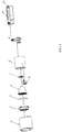
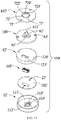
- FIG. 5 is a schematic structural view of an illuminating device comprising the foregoing control system and employing the foregoing control method.
- the illuminating device comprises a light-emitting source 1, a reflecting shade 4, a transmitting shade 5 and a lamp body 6, wherein the reflecting shade 4 covers the light-emitting source 1 and is expanded out towards the light-emitting direction of the light-emitting source 1, so as to adjust or control the light-emitting direction of the light-emitting source 1.
- the transmitting cover 5 covers a light outlet of the reflecting shade 4 for the optical control of final light emitting.
- a reflector holder 7 covers the transmitting shade 5 and is disposed on a light outlet of the lamp body 6, so as to fix components accommodated in the lamp body 6.
- the illuminating device further comprises a color recognition module 3 fixed on one side of the lamp body 6, and the detection direction of the color recognition module is consistent with the light-emitting direction of the light-emitting source 1 and is roughly parallel and level to the light outlet of the reflecting shade 4 and the transmitting shade 5.
- the color recognition module 3 is integrated onto the illuminating device and used for being cooperated with the reflected light acquiring module 20, the environment color acquiring module 40 and the target irradiating light acquiring module 60 to acquire the color of the reflected light generated by the illuminated object on the basis of the irradiating light and/or the environment color of the environment provided with the illuminating device.
- the illuminating device further comprises a control circuit board 2 for periodically starting the foregoing control method, so as to ensure that the irradiating light emitted by the light-emitting source 1 of the illuminating device can be rapidly adjusted when the illuminated object is replaced.
- a lamp body shade 8 is provided with an opening corresponding to the light exiting direction of the reflecting shade 4 fixed on the reflector holder 7 and the detection direction of the color recognition module 3, so as to provide convenience for light exiting and detection while providing fixing, protection and aesthetic property by covering the outside of the lamp body 6 and the color recognition module 3.
- a rotary support 9 is disposed at the rear of the lamp body 6 and connected with the control circuit board 2 and a power supply module 19, wherein the color recognition module 3 transmits data information of the illuminated object in the illumination direction of the light-emitting source 1, detected by the color recognition module, to the control circuit board 2 through the rotary support 9; subsequently, the control circuit board 2 is adopted to feed back corresponding light effect adjustment instruction; then the power supply module 19 controls the light-emitting source 1 to output corresponding light effect according to the corresponding light effect adjustment instruction.
- the light-emitting source 1 further includes: a light source unit, in which the light source unit preferably adopts an LED as a light source; light source paths formed by LED light sources of multiple colors are combined to form a mixed light array by using a RGB and RGBW light mixing mode; the functions of dimming and color mixing can be achieved by using the power supply module 19 to control the start and the brightness of the light source paths of multiple colors; thereby, the required light effect can be simulated and obtained.
- a light source unit in which the light source unit preferably adopts an LED as a light source
- light source paths formed by LED light sources of multiple colors are combined to form a mixed light array by using a RGB and RGBW light mixing mode
- the functions of dimming and color mixing can be achieved by using the power supply module 19 to control the start and the brightness of the light source paths of multiple colors; thereby, the required light effect can be simulated and obtained.
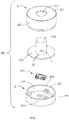
- FIGS. 6-9 and 10-13 respectively show the illuminating device provided with a color recognition module 100 in different embodiments.
- the color recognition module 100 includes: a housing 101, a PCB 102 accommodated in the housing 101, an optical lens 103 and a color detector 104 assembled on one side of the PCB 102, and a connector 105 assembled on the other side of the PCB 102.
- the housing 101 is made of insulating material(s) and includes a first cover body 11 and a second cover body 12 assembled together.
- the first cover body 11 includes a circular top wall 111 and a first side wall 112 extended from a side surface of the top wall 111.
- the top wall 111 of the first cover body 11 is provided with a first through hole 113 through which the lens 3 is exposed, and the first through hole 113 is circular.
- the second cover body 12 includes a bottom wall 121 and a second side wall 122 extended from a side surface of the bottom wall 121.
- the bottom wall 121 of the second cover body 12 is provided with a second through hole 123 through which the connector 105 is exposed, and two mounting holes 124 for the color recognition module 100 to be rapidly mounted on the illuminating device (not shown), and the second through hole 123 is rectangular.
- the second cover body 12 is also provided with a plurality of supporting blocks 125 disposed on an interface of the bottom wall 121 and the second side wall 122, in which at least two supporting blocks 125 are respectively provided with screw holes.
- the first cover body 11 and the second cover body 12 may be fastened together by the threaded connection between the first side wall 112 and the second side wall 122.
- the PCB 102 is circular and is disposed on the plurality of supporting blocks 125 in the second cover body 12. Positioning holes 21 are formed on and run through the PCB 2.
- the PCB 102 and the second cover body 12 may be positioned by bolts (not shown).
- the optical lens 103 is cylindrical, and one end of the optical lens is accommodated into and extended to the first through hole 113, so that the optical lens can receive external light.
- the main functions of the optical lens 103 include: collecting light within a specific range according to different specifications of the selected optical lens; and adjusting the intensity of light reaching a surface of the color detector 104, in which the light travels through the optical lens.
- the color detector 104 may be a color sensor, a spectral detector, a cadmium sulfide photoresistor, or any other element capable of acquiring colors.
- the color detector 104 is fixed on the PCB 102 and disposed between the optical lens 103 and the PCB 102.
- the external light arrives at the surface of the color detector 104 after travelling through the optical lens 103.
- the color detector 104 collects the reflected light of the illuminated object and outputs proper electric parameters according to the reflected light; and color information is obtained after the signal processing of the obtained electrical parameters, namely surface color information of the illuminated object is obtained.
- the color information includes the relative intensity of R, G, and B components.
- the RGB color mode is a color standard in the industry, which obtains a variety of colors by the variation of three RGB channels and the superposition of each other.
- R, G and B represent the color of the three RGB channels.
- the connector 105 may be welded on the PCB 102 by surface mount technology (SMT).
- SMT surface mount technology
- the color recognition module 100 in the preferred embodiment is assembled by the following steps.
- the specific steps include:
- the color recognition module 100 is assembled.
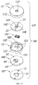
- a color recognition module 100' includes: a housing 101', a PCB 102' accommodated in the housing 101', an optical lens 103' and a color detector 104' assembled on one side of the PCB 102', and a connector 105' assembled on the other side of the PCB 102'.
- the color recognition module 100' also includes a first fastener 106' assembled on the housing 101'.
- the illuminating device includes a second fastener 107' cooperating with the first fastener 106' in a locking manner.
- the housing 101' is made of insulating material(s) and includes a first cover body 11' and a second cover body 12' assembled together.
- the first cover body 11' includes a circular top wall 111' and a first side wall 112' extended from a side surface of the top wall 111'.
- the top wall 111' of the first cover body 11' is provided with a first through hole 113' through which the optical lens 103' is exposed, and the first through hole 113' is circular.
- the lens 103' can be communicated with the outside via the first through hole 113'.
- An inner surface of the top wall 111' is also provided with a rectangular ring rib 114'.
- the rib 114' is disposed around the first through hole 113'.
- the second cover body 12' includes a bottom wall 121' and a second side wall 122' extended from a side surface of the bottom wall 121'.
- the bottom wall 121' of the second cover body 12' is provided with a second through hole 123' through which the connector 105' is exposed and two mounting holes 124', and the second through hole 123' is rectangular.
- the connector 105' can be communicated with the outside of the housing 101' via the second through hole 123'.
- the second cover body 12' is also provided with a plurality of supporting blocks 125' disposed on an interface of the bottom wall 121' and the second side wall 122', in which at least two supporting blocks 125' are respectively provided with screw holes 126'.
- the first cover body 11' and the second cover body 12' are fastened together by the threaded connection between the first side wall 112' and the second side wall 122'.
- the PCB 102' is circular and is disposed on the plurality of supporting blocks 125' in the second cover body 12'. Positioning holes 21' are formed on and run through the PCB 102'.
- the PCB 102' includes a positioning block 22'. The PCB 102' and the second cover body 12' may be positioned by bolts (not shown).
- the positioning block 22' is accommodated in an accommodating space (not marked) encircled by the rectangular ring rib 114', so as to position the PCB 102' and the first cover body 11'.
- the optical lens 103' is cylindrical and is disposed on the positioning block 22' of the PCB 102'.
- the optical lens 103' is accommodated in and extended to the first through hole 113'.
- the main functions of the optical lens 103' include: collecting light within a specific range according to different specifications of the selected optical lens 103', for instance, collecting ambient light or light emitted by an object; and adjusting the intensity of light reaching a surface of the color detector 104', in which the light travelling through the optical lens 103'.
- the color detector 104' can be a color sensor, a spectral detector, a cadmium sulfide photoresistor, or any other element capable of acquiring colors.
- the color detector 104' is fixed on the PCB 102' and disposed between the optical lens 103' and the PCB 102'.
- the external light arrives at the surface of the color detector 104' after travelling through the optical lens 103'.
- the color detector 104' collects the reflected light of the illuminated object and outputs proper electric parameters according to the reflected light; and color information is obtained after the signal processing of the obtained electrical parameters, namely surface color information of the illuminated object is obtained.
- the color information includes the relative intensity of R, G, and B components, namely chromaticity coordinate points of the colors.
- the RGB color mode is a color standard in the industry, which obtains a variety of colors by the variation of three RGB channels and the superposition of each other.
- R, G, and B represent the color of the three RGB channels.
- the connector 105' may be welded on the PCB 102' by SMT (Surface Mount Technology).
- the first fastener 106' is circular and is provided with a through hole 61', a recess 64' communicated with the through hole 61', and two screw holes 63'.
- the through hole 61' is disposed in the center of the first fastener 106', and the recess 64' is disposed on a surface contacting the second cover body 12'.
- the other surface of the first fastener 106' is provided with a tubular positioning part 62', and a locking block 621' is disposed on the positioning part 62'.
- the first fastener 106' may be fastened on the second cover body 12' by bolts (not marked).
- the color recognition module 100' in the preferred embodiment is assembled by the following steps.
- the specific steps include: assembling the optical lens' 103, the color detector 104' and the connector 105' on the PCB 102', and forming an assembly; and assembling the above assembly and fixing the assembly on the second cover body 12'; assembling the first cover body 11' on the second cover body 12'; and assembling the first fastener 106' on the second cover body 12'.
- the color recognition module 100' is assembled.
- the color recognition module 100' is provided with a fastener, namely the first fastener 106', the color recognition module 100' can be rapidly mounted on the illuminating device.
- a second fastener 107' on the illuminating device provided by the preferred embodiment is circular and is provided with a locking hole 71' for accommodating the positioning part 62' on the first fastener 106', and three stop blocks 72' disposed in the locking hole 71'.
- Each stop block 72' is provided with a depressed part 721' and ribs 722' and 723' disposed on two sides of the depressed part 721'. The height of the rib 723' is less than the height of the rib 722'.
- the positioning part 62' of the second fastener 107' is rotated for a certain angle after being accommodated into the locking hole 71', so that the locking block 621' can be accommodated in the depressed part 721' after passing over the lower rib 723' on the stop block 72'. Due to the limitation of the ribs 722' and 723', the second fastener 107' is stably fixed on the first fastener 106'. The second fastener 107' is mounted on the illuminating device. The through hole 61' and the locking hole 71' allow a connecting line to run through.
- the color recognition module 100' and the illuminating device can be rapidly connected by the fastening cooperation of the first fastener 106' and the second fastener 107'.
- the control system provided by the embodiments of the present invention corrects the initial reflected light of the illuminated object by acquiring the environment color, reduces the interference of the ambient light on the reflected light of the illuminated object, and obtains more precisely corrected color closer to the true color of the illuminated object, so that the illuminating device can select the irradiating light coordinated with the true color of the illuminated object.
Landscapes
- Circuit Arrangement For Electric Light Sources In General (AREA)
Description
- The present invention relates to the field of lighting technique, in particular to an illuminating device, a control method thereof and a control system thereof.
- With the rapid development of lighting technique, illumination is no longer confined to allow an illuminated object just to be illuminated, but escalated into a technique for enhancing the impression of the object by applying light effect in harmony with the color of the object to the illuminated object. The illuminating device can adaptively adjust the color of irradiating light of the illuminating device according to illuminated objects of different colors, so that the impression of the objects of different colors can all be enhanced. Thus, the illuminating device attracts more attention in the industry.
- In the prior art, the color of the irradiating light emitted by the illuminating device is generally adaptively adjusted by the following steps:
- S1: switching on the illuminating device to project detection light to an illuminated object, and acquiring reflected light of the illuminated object;
- S2: obtaining the color of the illuminated object according to the reflected light;
- S3: inquiring an irradiating light list according to the color, and acquiring target irradiating light; and
- S4: controlling the illuminating device to project the target irradiating light to the illuminated object.
- The inventor found that the prior art at least has the following problems:
as the environment provided with the illuminated object is inevitably provided with other objects or other illuminating devices, in the case of strong reflecting capacity of other objects to light, reflected light of other objects tend to be doped into the acquired reflected light of the illuminated object, so the color obtained according to the reflected light has large deviation from the true color of the illuminated object, and it is difficult for the illuminating device to select irradiating light coordinated with the true color of the illuminated object. -
US 2012/0280624 discloses a method wherein an additional color sensor is used for acquiring the environment color which is also considered when illuminating the object. - The objective of the embodiments of the present invention is to provide an illuminating device, a control method thereof and a control system thereof, which can precisely acquire the color of an illuminated object and adjust irradiating light emitted by the illuminating device according to the color of the object.
- In order to achieve the above objective, the present invention provides a control method of an illuminating device comprising a color detector, which comprises:
- switching on the illuminating device to project initial detection light to an illuminated object;
- detecting initial reflected light of the illuminated object by the color detector;
- obtaining an initial color of the illuminated object according to the initial reflected light;
- switching off the illuminating device projecting the initial detection light to the illuminated object;
- detecting an environment color of an environment provided with the illuminating device by the detector;
- correcting the initial color according to the environment color to obtain a corrected color;
- acquiring target irradiating light according to the corrected color; and
- controlling the illuminating device to project the target irradiating light to the illuminated object.
- Further, the control method comprises:
switching on and off the illuminating device to project the detection light to the illuminated object by modulating a pulse width modulation (PWM) signal according to a preset pulse width. - Further, the correcting of the initial color according to the environment color to obtain the corrected color specifically includes:
- determining whether the environment color satisfies a preset environment color condition, or not;
- obtaining a corrected color which is the same as the initial color when the environment color satisfies the preset condition;
- adjusting the color of the initial detection light and obtaining at least one kind of adjusted detection light when the environment color does not satisfy the preset condition;
- switching on the illuminating device to project the adjusted detection light to the illuminated object;
- acquiring adjusted reflected light of the illuminated object;
- comparing the colors between each of the adjusted reflected light and the initial reflected light, and obtaining reflected light color increments; and
- obtaining the corrected color of the illuminated object according to the adjusted reflected light with a maximum reflected light color increment.
- Further, the preset environment color condition specifically includes:
a value of the environment color is lower than the default environment color value. - Further, the adjusted detection light at least includes detection light of three primary color RGB.
- Further, the comparing of the color between each of the adjusted reflected light and the initial reflected light to obtain the reflected light color increments specifically includes:
obtaining reflected light RGB increments by the difference between the RGB value of each of the adjusted reflected light and the RGB value of the initial reflected light. - Further, the obtaining of the corrected color of the illuminated object according to the adjusted reflected light with the maximum reflected light color increment specifically includes:
- acquiring maximum primary color increment in all the reflected light RGB increments; and
- obtaining the corrected color of the illuminated object according to adjusted reflected light corresponding to the maximum primary color increment.
- Further, the initial detection light is white light.
- Further, the acquiring of the target irradiating light according to the corrected color specifically includes:
inquiring a target irradiating light list according to the corrected color, and acquiring the target irradiating light. - Further, the acquiring of the target irradiating light according to the corrected color specifically includes:
- controlling the illuminating device to project the initial irradiating light to the illuminated object, in which the color of the initial irradiating light is the corrected color;
- acquiring the color of reflected light generated by the illuminated object on the basis of the initial irradiating light;
- acquiring a target color according to the color of the reflected light generated on the basis of the initial irradiating light;
- controlling the illuminating device to project irradiating light to be selected to the
- illuminated object, in which the color of the irradiating light to be selected is in the target color;
- acquiring the color of reflected light generated by the illuminated object on the basis of the irradiating light to be selected; and
- determining whether a color difference between the reflected light generated on the basis of the initial irradiating light and the reflected light generated on the basis of the irradiating light to be selected is within a preset color difference range, or not, if yes, taking the irradiating light to be selected as the target irradiating light.
- In order to achieve the above objective, the present invention provides a control system of an illuminating device, which comprises:
- a detection light switching module for switching on the illuminating device to project initial detection light to an illuminated object;
- an initial reflected light acquiring module for acquiring initial reflected light of the illuminated object;
- an initial color operation module for obtaining an initial color of the illuminated object according to the initial reflected light;
- the detection light switching module being used for switching off the illuminating device projecting the initial detection light to the illuminated object;
- an environment color acquiring module for acquiring an environment color of an environment provided with the illuminating device;
- an initial color correcting module for correcting the initial color according to the environment color to obtain a corrected color;
- a target irradiating light acquiring module for acquiring target irradiating light according to the corrected color; and
- a target irradiating light start module for controlling the illuminating device to project the target irradiating light to the illuminated object.
- A detector is cooperatively used by the initial reflected light acquiring module and the environment color acquiring module.
- Further, the control system comprises:
the detection light switching module controls the "On" and "Off of the illuminating device to project the detection light to the illuminated object by modulating a PWM signal according to the preset pulse width. - Further, the initial color correcting module is specifically used for:
- determining whether the environment color satisfies the preset environment color condition, or not;
- obtaining a corrected color which is the same as the initial color when the environment color satisfies the preset condition;
- adjusting the color of the initial detection light to obtain at least one kind of adjusted detection light when the environment color does not satisfy the preset condition;
- switching on the illuminating device to project the adjusted detection light to the illuminated object, and acquiring adjusted reflected light of the illuminated object;
- comparing the colors between each of the adjusted reflected light and the initial reflected light to obtain reflected light color increments; and
- obtaining the corrected color of the illuminated object according to adjusted reflected light with maximum reflected light color increment.
- Further, the preset environment color condition specifically includes:
a value of the environment color is lower than the preset environment color value. - Further, the adjusted detection light at least includes detection light of RGB three primary colors.
- Further, the initial color correcting module is specifically used for:
obtaining reflected light RGB increments by the difference between the RGB value of each of the adjusted reflected light and the RGB value of the initial reflected light. - Further, the initial color correcting module is specifically used for:
- acquiring a maximum primary color increment in all of the reflected light RGB increments; and
- obtaining the corrected color of the illuminated object according to adjusted reflected light corresponding to the maximum primary color increment.
- Further, the initial detection light is white light.
- Further, the target irradiating light acquiring module is specifically used for:
inquiring a target irradiating light list according to the corrected color, and acquiring the target irradiating light. - Further, the target irradiating light acquiring module is specifically used for:
- controlling the illuminating device to project the initial irradiating light to the illuminated object, in which the color of the initial irradiating light is the corrected color;
- acquiring the color of reflected light generated by the illuminated object on the basis of the initial irradiating light;
- acquiring a target color according to the color of the reflected light generated on the basis of the initial irradiating light;
- controlling the illuminating device to project irradiating light to be selected to the illuminated object, in which the color of the irradiating light to be selected is in the target color;
- acquiring the color of reflected light generated by the illuminated object on the basis of the irradiating light to be selected; and
- determining whether a color difference between the reflected light generated on the basis of the initial irradiating light and the reflected light generated on the basis of the irradiating light to be selected is within the preset color difference range, if yes, taking the irradiating light to be selected as the target irradiating light.
- In order to achieve the above objective, the present invention provides an illuminating device, which comprises:
- a light-emitting source;
- a power drive unit for adjusting the power supplied for the light-emitting source; and
- the control system as the previously described invention, in which the control system is electrically connected with the light-emitting source and the power drive unit.
- Further, it further comprises a color recognition module, in which the color recognition module is integrated onto the illuminating device and used for being cooperated with the initial reflected light acquiring module, the environment color acquiring module and the target irradiating light acquiring module acquiring the color of the reflected light generated by the illuminated object on the basis of the irradiating light and/or the environment color of the environment provided with the illuminating device, and it includes: a housing, a printed circuit board (PCB) accommodated in the housing, and a color detector mounted on one side of the PCB.
- Further, the color recognition module also includes a connector mounted on the other side of the PCB and connected to the illuminating device; the connector being extended out of the housing and communicated with the outside of the housing.
- Further, the color recognition module further includes a first fastener mounted on the housing; and the illuminating device includes a second fastener; the first fastener and the second fastener being connected in a locking manner.
- Further, the color recognition module is disposed adjacent to the light-emitting source and detects the color of the illuminated object towards the illumination direction of the light-emitting source.
- Further, the illuminating device has a lamp body; and both the color recognition module and the light-emitting source are accommodated in the lamp body.
- Further, the illuminating device is self-adapting spotlights and further comprises a reflecting shade, a transmitting shade and a lamp body, in which the reflecting shade covers the light-emitting source and is expanded out towards the light-emitting direction of the light-emitting source, and the transmitting shade covers a light outlet of the reflecting shade.
- As can be seen from the technical proposals of the embodiments of the present invention, the embodiments of the present invention correct the initial reflected light of the illuminated object by acquiring the environment color, reduce the interference of the ambient light on the reflected light of the illuminated object, and obtain more precise corrected color closer to the true color of the illuminated object, so that the illuminating device can select the irradiating light coordinated with the true color of the illuminated object.
- For more clear description of the technical proposals in the embodiments of the present invention or in the prior art, simple description will be given below to the accompanying drawings required to be used in the description of the embodiments or the prior art. It is apparent that the accompanying drawings described below are only some embodiments of the present invention, and other accompanying drawings may also be obtained by an ordinary skill in the art without creative efforts according to the accompanying drawings.
-
FIG. 1 is a flow chart of a control method of an illuminating device, provided by an embodiment of the present invention; -
FIG. 2 is a specific flowchart illustrating the step of correcting the initial color according to the environment color to obtain a corrected color, in the control method of the illuminating device provided by an embodiment of the present invention; -
FIG. 3 is a specific flowchart illustrating the step of obtaining the corrected color of the illuminated object according to adjusted reflected light with maximum reflected light color increment, in the control method of the illuminating device provided by an embodiment of the present invention; -
FIG. 4 is a block diagram of a control system of an illuminating device, provided by an embodiment of the present invention; -
FIG. 5 is an assembly diagram of an illuminating device provided by an embodiment of the present invention; -
FIG. 6 is a perspective assembly diagram of a color recognition module in the preferred embodiment of the present invention; -
FIG. 7 is a perspective assembly diagram of the color recognition module in the preferred embodiment of the present invention, from another view; -
FIG. 8 is a perspective exploded view ofFIG. 6 ; -
FIG. 9 is a perspective exploded view ofFIG. 7 ; -
FIG. 10 is a perspective assembly diagram of a color recognition module provided by another preferred embodiment of the present invention; -
FIG. 11 is a perspective assembly diagram of the color recognition module provided by another preferred embodiment of the present invention, from another view; -
FIG. 12 is a perspective exploded view ofFIG. 10 ; and -
FIG. 13 is a perspective exploded view ofFIG. 11 . - Embodiments of the present invention provide an illuminating device, a control method thereof and a control system thereof.
- In order to make the technical proposals of the present invention more understandable by those skilled in the art, the technical solutions according to the embodiments of the present invention will be described clearly and fully as below in conjunction with the accompanying drawings of embodiments of the present invention. It is apparent that the described embodiments are just a part but not all of the embodiments of the invention. Based on the described embodiments herein, a person of ordinary skill in the art can obtain other embodiment(s), without any creative work, which shall be within the scope of the present invention.
- In the process of adjusting the irradiating light emitted by the illuminating device by acquiring different colors of the illuminated object via the projection of the detection light in the prior art, the problem of difficult selection of the irradiating light coordinated with the true color of the illuminated object, caused by the large color recognition deviation of the object due to reflected light of other objects, may occur. The embodiments of the present invention provide a control method of an illuminating device for solving the above problem. Detailed description will be given below to the method with reference to the accompanying drawings.
-
FIG. 1 is a flow chart of a control method of an illuminating device, provided by an embodiment of the present invention. An executive body of the control method may be a control circuit board mounted in the illuminating device. The control circuit board is provided with multiple elements, such as a micro control unit (MCU), and a sensor. The elements are electrically connected with a plurality of elements in the illuminating device, such as a light-emitting source, a power drive unit, and a possible power supply by wired or wireless means. - During the regular illumination of the illuminated object by the light-emitting source of the illuminating device, the control circuit board periodically starts the foregoing control method, so as to ensure that the irradiating light emitted by the light-emitting source of the illuminating device can be rapidly adjusted when the illuminated object is replaced.
- The foregoing control method comprises the following steps.
- S10: switching on the illuminating device to project initial detection light to the illuminated object.
- In the embodiment of the present invention, the light-emitting source of the illuminating device may be adopted to project the initial detection light. In the process of starting the control method, the irradiating light originally emitted by the light-emitting source of the illuminating device is turned off in advance, then, the projection of the detection light is switched on.
- Of course, another independent auxiliary light-emitting source may also be disposed in the illuminating device. After the irradiating light originally emitted by the light-emitting source of the illuminating device is turned off, for the projection of the detection light through the auxiliary light-emitting source, the auxiliary light-emitting source is only required to be electrically connected with the drive unit and the power supply of the illuminating device. No further description will be given here.
- In the embodiment of the present invention, the initial detection light may be white light, and the color temperature of the white light may be 2,000K-30,000K and may also be within a smaller range of 2,500-25,000K. As the white light has large optical width and there is no interference of light of other colors at the time, the reflected light of the illuminated object can be more accurately obtained.
- Of course, the initial detection light may also adopt light of other colors except the white light. No further description will be given here.
- No matter the light-emitting source of the illuminating device, or the independent auxiliary light-emitting source, a light-emitting diode (LED) may be used as the light source; light source paths formed by LED light sources of multiple colors are combined to form a mixed light array by using a RGB and RGBW light mixing mode; and the functions of dimming and color mixing can be achieved by using the drive unit to control the start and the brightness of the light source paths with the multiple colors.
- Of course, no matter the light-emitting source of the illuminating device, or the independent auxiliary light-emitting source, other types, such as TL lamps, and halogen lamps may also be used. No further description will be given here.
- S20: acquiring initial reflected light of the illuminated object.
- In the embodiment of the present invention, a color recognition module facing the illuminated object may be disposed on the illuminating device. The color recognition module is adopted to acquire the initial reflected light on the basis of the initial detection light, and convert the initial reflected light into RGB electrical signals for embodying color. The technology is known by an ordinary skill in the art. No further description will be given here. The color recognition module may be a color sensor, a cadmium sulfide photoresistor described blow, or any other element capable of acquiring color.
- S30: obtaining an initial color of the illuminated object according to the initial reflected light.
- In the embodiment of the present invention, the initial color of the illuminated object may be obtained by the comparison between the ratio of the RGB electrical signals in the initial reflected light and a preset color table. The initial color is relevant to the preset color of the object, so that each initial color can embody one corresponding color of the illuminated object. Subsequently, the type of the illuminated object may also be obtained according to the application scene of the illuminating device.
- The foregoing preset color table may be stored into a color memory. The color memory may be disposed in the executive body of the control method, namely the control circuit.
- Of course, in other embodiments of the present invention, the initial color of the illuminated object may also be acquired by other ways. For instance, the reflected light may be detected by a cadmium sulfide photoresistor close to a sensitometric curve of the human eyes. As the photoresistor will have different resistance variations for different colors, the initial color may also be deducted according to the resistance variation. No further description will be given here.
- S40: switching off the illuminating device projecting the initial detection light to the illuminated object.
- In the embodiment of the present invention, in the process of executing the control method, the light-emitting source in the illuminating device is turned on and off to project the detection light to the illuminated object by modulating a PWM signal according to the preset pulse width, so that the illuminating device is periodically switched on and off to project the initial detection light to the illuminated object. In this way, the subsequent acquisition of the environment color of the environment provided with the illuminating device will not be affected by the irradiating light emitted by the illuminating device.
- It is imperceptible by an observer for the "on" and "off' of the light-emitting source in the illuminating device by increasing the frequency of the PWM signal, so that the user experience can be guaranteed.
- S50: acquiring an environment color of an environment provided with the illuminating device.
- In the embodiment of the present invention, the color recognition module for collecting the reflected light may be adopted to acquire the environment color of the environment provided with the illuminating device. The environment color embodies multiple color impurities possibly being doped into the reflected light of the illuminated object, for instance, reflected light of other objects except the illuminated object or reflected light of other illuminating devices. As the projection of the initial detection light to the illuminated object via the illuminating device has been turned off, the acquired environment color will not be affected by the irradiating light emitted by the illuminating device, so the accuracy of the environment color can be guaranteed.
- S60: correcting the initial color according to the environment color to obtain a corrected color.
- The embodiment of the present invention obtains adjusted reflected light by correcting the initial reflected light of the illuminated object according to the environment color, and obtains the corrected color according to the adjusted reflected light, which can reduce the interference of the ambient light on the reflected light of the illuminated object, and obtain more precisely corrected color closer to the true color of the illuminated object.
- With reference to
FIG. 2 , in the embodiment of the present invention, the step S60 specifically includes the following steps:
S61: determining whether the environment color satisfies the preset environment color condition, or not; if yes, executing the step S62; if no, executing the step S63. - The preset environment color condition specifically includes: the value of the environment color is lower than the preset environment color value. The preset light value may be preset according to the environment provided with the illuminating device. For instance, in a shopping mall with multiple ambient lights, the preset environment color value may be adaptively increased to reduce the interference of the ambient light on the reflected light of the illuminated object.
- S62: obtaining a corrected color which is the same as the initial color.
- When the environment color is within an acceptable range, the interference of the ambient light on the reflected light of the illuminated object may be ignored. At this point, the corrected color which is the same as the initial color is directly selected, and the acquired color of the illuminated object is basically the same as the true color of the illuminated object.
- S63: adjusting the color of the initial detection light, and obtaining at least one kind of adjusted detection light.
- When the environment color exceeds the acceptable range, the interference of the ambient light on the reflected light of the illuminated object is large, so the interference of the ambient light on the reflected light of the illuminated object is required to be reduced.
- In the embodiment of the present invention, when the light-emitting source of the illuminating device is adopted to emit the detection light, all of the irradiating light having different colors from the initial detection light, capable of being emitted by the light-emitting source, may be acquired in advance, and the irradiating light is taken as the adjusted detection light.
- Taking the case that the initial detection light is white light and the light-emitting source of the illuminating device can also emit light of RGB three primary colors as an example, the adjusted detection light may adopt at least one of the light of the RGB three primary colors.
- Of course, the adjusted detection light is not limited to be the foregoing light of the RGB three primary colors and may also include light of other colors, such as pink and purple. No further description will be given here.
- S64: switching on the illuminating device to project the adjusted detection light to the illuminated object.
- S65: acquiring adjusted reflected light of the illuminated object.
- In the embodiment of the present invention, taking the case that the adjusted detection light may adopt the light of the RGB three primary colors as an example, the light-emitting source of the illuminating device is turned on to sequentially project the adjusted irradiating light of the RGB three primary colors to the illuminated object, and the adjusted reflected light generated by the illuminated object is sequentially acquired.
- S66: comparing the colors between each of the adjusted reflected light and the initial reflected light, and obtaining reflected light color increments.
- Both the adjusted reflected light and the initial reflected light include two parts: one is the color impurities caused by multiple ambient lights; and the other is standard reflected light generated on the basis of the adjusted detection light or the initial detection light.
- No matter the adjusted detection light or the initial detection light, the surrounding environment may be confirmed to be basically the same within a relatively short period of time, namely the color impurities caused by the ambient light are basically unchanged, so the reflected light color increments obtained by the differencing of the adjusted reflected light and the initial reflected light will not include the color impurities caused by the ambient light, namely the reflected light color increments will not be affected by the ambient light.
- In the embodiment of the present invention, as light will be automatically converted into RGB values after being collected by the color recognition module, all the reflected light RGB increments may be obtained by the differencing of the RGB value of each of the adjusted reflected light and the RGB value of the initial reflected light, which is convenient for the calculating of the reelected light RGB increments.
- S67: obtaining the corrected color of the illuminated object according to adjusted reflected light with maximum reflected light color increment.
- With reference to
FIG. 3 , in the embodiment of the present invention, the step S66 specifically includes the following steps:
S661: acquiring a maximum primary color increment in all of the reflected light RGB increments. - Each reflected light RGB increment includes values of RGB three primary colors; three groups of primary color increments are obtained by differencing two reflected light RGB increments, namely differencing the values of the RGB three primary colors, respectively; and the three groups of primary color increments are gathered to be the reflected light RGB increment.
- Taking the case that the adjusted detection light may adopts the light of the RGB three primary colors as an example, the obtained 3 groups of reflected light RGB increments are specifically as shown in Table 1.
Table 1 Adjusted Detection Light R G B Reflected Light RGB Increment (65,15,20) (25, 40, 23) (18,35,38) - It can be apparently obtained from the data in the Table 1 that: when the adjusted detection light is R light, the R increment in the reflected light RGB increment is 65 and is greater than the
maximum G increment 40 and the maximum B increment 38, so the maximum primary color increment is disposed in the reflected light RGB increment when the adjusted detection light is R light. - S662: obtaining the corrected color of the illuminated object according to adjusted reflected light corresponding to the maximum primary color increment.
- According to the principle that the object has the strongest reflecting capacity on light of the same color, it can be obtained that the true color of the illuminated object is closer to red. Thus, the corrected color is obtained by correcting the initial color towards red.
- Of course, the magnitude of correcting the initial color towards red may be preset according to the range of the maximum primary color increment. When the maximum primary color increment is larger, the initial color may be closer to the maximum primary color. The technology is known by an ordinary skill in the art. No further description will be given here.
- S70: acquiring target irradiating light according to the corrected color.
- In the embodiment of the present invention, in the step S70, the target irradiating light may be obtained by inquiring a preset irradiating light list according to the corrected color. The irradiating light list is preset according to the environment provided with the illuminating device and the type of the illuminated object, and it includes a plurality of color ranges of the illuminated object and the color of irradiating light corresponding to each color range.
- For instance, when the illuminating device is applied in a supermarket and the illuminated object is meat, vegetables, or other goods, it can be obtained that the goods are mostly coordinated with irradiating light of which colors by experiences on the goods, such as meat, and vegetables, and finally the color data are gathered to obtain the foregoing irradiating light list.
- Of course, in other embodiments of the present invention, in the step S70, the target irradiating light may also be obtained by the following steps:
- controlling the illuminating device to project initial irradiating light to the illuminated object, in which the color of the initial irradiating light is the corrected color;
- acquiring the color of reflected light generated by the illuminated object on the basis of the initial irradiating light;
- acquiring a target color according to the color of the reflected light generated on the basis of the initial irradiating light;
- controlling the illuminating device to project irradiating light to be selected to the illuminated device, in which the color of the irradiating light to be selected is the target color;
- acquiring the color of reflected light generated by the illuminated object on the basis of the irradiating light to be selected; and
- determining whether the color difference between the reflected light generated on the basis of the initial irradiating light and the reflected light generated on the basis of the irradiating light to be selected is within a preset color difference range, if yes, taking the irradiating light to be selected as the target irradiating light.
- S80: controlling the illuminating device to project the target irradiating light to the illuminated object.
- The control method provided by the embodiment of the present invention corrects the initial reflected light of the illuminated object by acquiring the environment color, which can reduce the interference of the ambient light on the reflected light of the illuminated object, and obtain more precisely corrected color closer to the true color of the illuminated object, so that the illuminating device can select irradiating light coordinated with the true color of the illuminated object.
-
FIG. 4 is a block diagram of a control system of an illuminating device, provided by an embodiment of the present invention. - The control system may be operated via a control circuit board mounted in the illuminating device. The control circuit board includes multiple elements, such as an MCU, and a sensor. The elements are electrically connected with a plurality of elements in the illuminating device, such as a light-emitting source, a power drive unit, and a possible power supply.
- During the regular illumination of the illuminated object by the light-emitting source of the illuminating device, the control circuit board periodically starts the foregoing control system, so as to ensure that the irradiating light emitted by the light-emitting source of the illuminating device can be rapidly adjusted when the illuminated object is replaced.
- The foregoing control system comprises the following modules:
A detectionlight switching module 10 is used for switching on the illuminating device to project initial detection light to the illuminated object. - In the embodiment of the present invention, the light-emitting source of the illuminating device may be adopted to project the initial detection light. In the process of starting the control system, the irradiating light originally emitted by the light-emitting source of the illuminating device is turned off in advance, and subsequently the illuminating device is switched on to project the detection light.
- Of course, another independent auxiliary light-emitting source may also be disposed in the illuminating device. After the irradiating light originally emitted by the light-emitting source of the illuminating device is turned off, for the projection of the detection light through the auxiliary light-emitting source, the auxiliary light-emitting source is only required to be electrically connected with the drive unit and the power supply of the illuminating device. No further description will be given here.
- In the embodiment of the present invention, the initial detection light may be white light, and the color temperature of the white light may be 2,000K-30,000K and may also be within a smaller range of 2,500-25,000K. As the white light has large optical width and there is no interference of light of other colors at the time, the reflected light of the illuminated object can be more accurately obtained.
- Of course, the initial detection light may also adopt light of other colors except the white light. No further description will be given here.
- No matter the light-emitting source of the illuminating device or the independent auxiliary light-emitting source, an LED may be used as the light source; light source paths formed by LED light sources of multiple colors are combined to form a mixed light array by using a RGB and RGBW light mixing mode; and the functions of dimming and color mixing can be achieved by using the drive unit to control the start and the brightness of the light source paths of the multiple colors.
- Of course, no matter the light-emitting source of the illuminating device, or the independent auxiliary light-emitting source, other types, such as TL lamps, and halogen lamps, may also be used. No further description will be given here.
- An initial reflected light acquiring
module 20 used for acquiring initial reflected light of the illuminated object. - In the embodiment of the present invention, the color recognition module facing the illuminated object may be disposed on the illuminating device. The color recognition module is adopted to acquire reflected light on the basis of the initial detection light, and convert the reflected light into initial reflected light embodied in the form of RGB electrical signals. The technology is known by an ordinary skill in the art. No further description will be given here.
- An initial
color operation module 30 is used for obtaining initial color of the illuminated object according to the initial reflected light. - In the embodiment of the present invention, the initial color of the illuminated object may be obtained by the comparison between the ratio of the RGB electrical signals in the initial reflected light and a preset color table. The initial color is relevant to the preset color of the object, so that each initial color can embody one corresponding color of the illuminated object. Subsequently, the type of the illuminated object may also be obtained according to the application scene of the illuminating device.
- The foregoing preset color table may be stored into a color memory. The color memory may be disposed in an executive body, namely a control circuit, of the control system.
- Of course, in other embodiments of the present invention, the initial color of the illuminated object may also be acquired by other ways. For instance, the reflected light may be detected by a cadmium sulfide photoresistor close to a sensitometric curve of the human eyes. As the photoresistor will have different resistance variations for different colors, the initial color may also be deducted according to the resistance variation. No further description will be given here.
- The detection
light switching module 10 is also used for switching off the illuminating device projecting the initial detection light to the illuminated object. - In the embodiment of the present invention, in the operation of the control system, the detection light switching module and the detection light switching module may be disposed in the same controller, and the illuminating device is switched on and off to project the detection light to the illuminated object by modulating a PWM signal according to the preset pulse width inputted into the controller.
- The light-emitting source in the illuminating device is turned on and off to project the detection light to the illuminated object by modulating the PWM signal according to the preset pulse width, so that the illuminating device is periodically switched on and off to project the initial detection light to the illuminated object.
- It is imperceptible by an observer for the "on" and "off' of the light-emitting source in the illuminating device by increasing the frequency of the PWM signal, so that the user experience can be guaranteed.
- An environment
color acquiring module 40 is used for acquiring environment color of an environment provided with the illuminating device. - In the embodiment of the present invention, the color recognition module for collecting the reflected light may be adopted to acquire the environment color of the environment provided with the illuminating device. The environment color embodies multiple color impurities possibly being doped into the reflected light of the illuminated object, for instance, reflected light of other objects except the illuminated object, or reflected light of other illuminating devices. As the projection of the initial detection light to the illuminated object by the illuminating device has been turned off, the acquired environment color will not be affected by the irradiating light emitted by the illuminating device, so the accuracy of the environment color can be guaranteed.
- An initial
color correcting module 50 is used for correcting the initial color according to the environment color to obtain a corrected color. - The embodiment of the present invention obtains adjusted reflected light by correcting the initial reflected light of the illuminated object according to the environment color, and obtains the corrected color according to the adjusted reflected light, which can reduce the interference of the ambient light on the reflected light of the illuminated object, and obtain more precisely corrected color closer to the true color of the illuminated object.
- In the embodiment of the present invention, the initial
color correcting module 50 includes:
A preset condition determination module specifically used for determining whether the environment color satisfies the preset environment color condition, or not. - The preset environment color condition specifically includes: the value of the environment color is lower than the preset environment color value. The preset light value may be preset according to the environment provided with the illuminating device. For instance, in a shopping mall with multiple ambient lights, the preset environment color value may be adaptively increased, so as to reduce the interference of the ambient light on the reflected light of the illuminated object.
- A correction execution module is used for obtaining a corrected color which is the same as the initial color when the environment color satisfies the preset condition.
- When the environment color is within an acceptable range, the interference of the ambient light on the reflected light of the illuminated object may be ignored. At this point, the corrected color which is the same as the initial color is directly selected, and the acquired color of the illuminated object is basically the same as the true color of the illuminated object.
- The correction execution module is used for adjusting the color of the initial detection light and obtaining at least one kind of adjusted detection lights when the environment color does not satisfy the preset condition.
- When the environment color exceeds the acceptable range, the interference of the ambient light on the reflected light of the illuminated object is large, so the interference of the ambient light on the reflected light of the illuminated object is required to be reduced.
- In the embodiment of the present invention, when the light-emitting source of the illuminating device is adopted to emit the detection light, all of the irradiating light having different colors from the initial detection light, capable of being emitted by the light-emitting source, may be acquired in advance, and the irradiating light is used as the adjusted detection light.
- Taking the case that the initial detection light is white light and the light-emitting source of the illuminating device can also emit light of RGB three primary colors as an example, the adjusted detection light may adopt at least one of the lights of the RGB three primary colors.
- Of course, the adjusted detection light is not limited to be the foregoing light of the RGB three primary colors and may also include light of other colors, such as pink, or purple. No further description will be given here.
- An adjusted detection light switching module is used for switching on the illuminating device to project adjusted detection light to the illuminated object, and acquiring adjusted reflected light of the illuminated object.
- In the embodiment of the present invention, taking the case that the adjusted detection light may adopt the light of the RGB three primary colors as an example, the light-emitting source of the illuminating device is turned on to sequentially project the adjusted irradiating light of the RGB three primary colors to the illuminated object, and the adjusted reflected light generated by the illuminated object is sequentially acquired.
- A reflected light color increment operation module is used for obtaining reflected light color increments by the comparison of the color between each of the adjusted reflected light and the initial reflected light in turn.
- Both the adjusted reflected light and the initial reflected light include two parts: one is the color impurities caused by multiple ambient lights; and the other is standard reflected light generated on the basis of the adjusted detection light, or the initial detection light.
- No matter the adjusted detection light, or the initial detection light, the surrounding environment may be confirmed to be basically the same within a relatively short period of time, namely the color impurities caused by the ambient light are basically unchanged, so the reflected light color increments obtained by the differencing of the adjusted reflected light and the initial reflected light will not include the color impurities caused by the ambient light, namely the reflected light color increments will not be affected by the ambient light.
- In the embodiment of the present invention, as light will be automatically converted into RGB values after being collected by the color recognition module, all of the reflected light RGB increments may be obtained by the differencing of the RGB value of each of the adjusted reflected light and the RGB value of the initial reflected light, which is convenient for calculating the reelected light RGB increments.
- A corrected color operation module is used for obtaining a corrected color of the illuminated object according to adjusted reflected light with the maximum reflected light color increment.
- In the embodiment of the present invention, the reflected light color increment operation module specifically includes:
a maximum primary color increment acquiring module used for acquiring the maximum primary color increment in all of the reflected light RGB increments. - Each reflected light RGB increment includes values of RGB three primary colors; three groups of primary color increments are obtained by the differencing of two reflected light RGB increments, namely differencing the values of the RGB three primary colors, respectively; and the three groups of primary color increments are gathered to be the reflected light RGB increment.
- Taking the case that the adjusted detection light may adopt the light of the RGB three primary colors as an example, the obtained three groups of reflected light RGB increments are specifically shown in Table 2.
Table 2 Adjusted Detection Light Red Green Blue Reflected Light RGB Increment (65,15,20) (25, 40, 23) (18,35,38) - It can be apparently obtained from data in the Table 2 that: when the adjusted detection light is R light, the R increment in the reflected light RGB increment is 65 and is greater than the
maximum G increment 40 and the maximum B increment 38, so the maximum primary color increment is disposed in the reflected light RGB increment when the adjusted detection light is R light. - A maximum primary color increment processing module is used for obtaining the corrected color of the illuminated object according to adjusted reflected light corresponding to the maximum primary color increment.
- According to the principle that the object has the strongest reflecting capacity on light of the same color, it can be obtained that the true color of the illuminated object is closer to red. In this way, the corrected color is obtained by correcting the initial color towards red.
- Of course, the magnitude of correcting the initial color towards red may be preset according to the range of the maximum primary color increment. When the maximum primary color increment is larger, the initial color may be closer to the maximum primary color. The technology is known by an ordinary skill in the art. No further description will be given here.
- A target irradiating light acquiring module 60 is used for acquiring target irradiating light according to the corrected color.
- In the embodiment of the present invention, the target irradiating light acquiring module 60 obtains the target irradiating light by inquiring a preset irradiating light list according to the corrected color. The irradiating light list is preset according to the environment provided with the illuminating device and the type of the illuminated object, and it includes a plurality of color ranges of the illuminated object and the color of irradiating light corresponding to each color range.
- For instance, when the illuminating device is applied in a supermarket and the illuminated object is meat, vegetables, or other goods, it can be obtained that the goods are mostly coordinated with irradiating light of which colors by experiences on the goods, such as meat, and vegetables, and finally the color data are gathered to obtain the foregoing irradiating light list.
- Of course, in other embodiments of the present invention, the target irradiating light acquiring module 60 may also obtain the target irradiating light by the following ways:
- controlling the illuminating device to project initial irradiating light to the illuminated object, in which the color of the initial irradiating light is the corrected color;
- acquiring the color of reflected light generated by the illuminated object on the basis of the initial irradiating light;
- acquiring target color according to the color of the reflected light generated on the basis of the initial irradiating light;
- controlling the illuminating device to project irradiating light to be selected to the illuminated device, in which the color of the irradiating light to be selected is the target color;
- acquiring the color of reflected light generated by the illuminated object on the basis of the irradiating light to be selected; and
- determining whether the color difference between the reflected light generated on the basis of the initial irradiating light and the reflected light generated on the basis of the irradiating light to be selected is within a preset color difference range, is yes, taking the irradiating light to be selected as the target irradiating light.
- A target irradiating
light start module 70 is used for controlling the illuminating device to project the target irradiating light to the illuminated object. -
FIG. 5 is a schematic structural view of an illuminating device comprising the foregoing control system and employing the foregoing control method. The illuminating device comprises a light-emitting source 1, a reflectingshade 4, a transmitting shade 5 and alamp body 6, wherein the reflectingshade 4 covers the light-emitting source 1 and is expanded out towards the light-emitting direction of the light-emitting source 1, so as to adjust or control the light-emitting direction of the light-emitting source 1. The transmitting cover 5 covers a light outlet of the reflectingshade 4 for the optical control of final light emitting. A reflector holder 7 covers the transmitting shade 5 and is disposed on a light outlet of thelamp body 6, so as to fix components accommodated in thelamp body 6. - The illuminating device further comprises a color recognition module 3 fixed on one side of the
lamp body 6, and the detection direction of the color recognition module is consistent with the light-emitting direction of the light-emitting source 1 and is roughly parallel and level to the light outlet of the reflectingshade 4 and the transmitting shade 5. The color recognition module 3 is integrated onto the illuminating device and used for being cooperated with the reflectedlight acquiring module 20, the environmentcolor acquiring module 40 and the target irradiating light acquiring module 60 to acquire the color of the reflected light generated by the illuminated object on the basis of the irradiating light and/or the environment color of the environment provided with the illuminating device. The illuminating device further comprises a control circuit board 2 for periodically starting the foregoing control method, so as to ensure that the irradiating light emitted by the light-emitting source 1 of the illuminating device can be rapidly adjusted when the illuminated object is replaced. - A lamp body shade 8 is provided with an opening corresponding to the light exiting direction of the reflecting
shade 4 fixed on the reflector holder 7 and the detection direction of the color recognition module 3, so as to provide convenience for light exiting and detection while providing fixing, protection and aesthetic property by covering the outside of thelamp body 6 and the color recognition module 3. Arotary support 9 is disposed at the rear of thelamp body 6 and connected with the control circuit board 2 and a power supply module 19, wherein the color recognition module 3 transmits data information of the illuminated object in the illumination direction of the light-emitting source 1, detected by the color recognition module, to the control circuit board 2 through therotary support 9; subsequently, the control circuit board 2 is adopted to feed back corresponding light effect adjustment instruction; then the power supply module 19 controls the light-emitting source 1 to output corresponding light effect according to the corresponding light effect adjustment instruction. - Specifically, the light-emitting source 1 further includes: a light source unit, in which the light source unit preferably adopts an LED as a light source; light source paths formed by LED light sources of multiple colors are combined to form a mixed light array by using a RGB and RGBW light mixing mode; the functions of dimming and color mixing can be achieved by using the power supply module 19 to control the start and the brightness of the light source paths of multiple colors; thereby, the required light effect can be simulated and obtained.
-
FIGS. 6-9 and10-13 respectively show the illuminating device provided with acolor recognition module 100 in different embodiments. - As shown in
FIGS. 6-9 , in an embodiment, thecolor recognition module 100 includes: ahousing 101, aPCB 102 accommodated in thehousing 101, anoptical lens 103 and acolor detector 104 assembled on one side of thePCB 102, and aconnector 105 assembled on the other side of thePCB 102. - Detailed description will be given below to elements in the
color recognition module 100 in the preferred embodiment. - As shown in
FIGS. 6 ,8 and9 , thehousing 101 is made of insulating material(s) and includes afirst cover body 11 and asecond cover body 12 assembled together. Thefirst cover body 11 includes a circulartop wall 111 and afirst side wall 112 extended from a side surface of thetop wall 111. Thetop wall 111 of thefirst cover body 11 is provided with a first throughhole 113 through which the lens 3 is exposed, and the first throughhole 113 is circular. Thesecond cover body 12 includes abottom wall 121 and asecond side wall 122 extended from a side surface of thebottom wall 121. Thebottom wall 121 of thesecond cover body 12 is provided with a second throughhole 123 through which theconnector 105 is exposed, and two mountingholes 124 for thecolor recognition module 100 to be rapidly mounted on the illuminating device (not shown), and the second throughhole 123 is rectangular. Thesecond cover body 12 is also provided with a plurality of supportingblocks 125 disposed on an interface of thebottom wall 121 and thesecond side wall 122, in which at least two supportingblocks 125 are respectively provided with screw holes. Thefirst cover body 11 and thesecond cover body 12 may be fastened together by the threaded connection between thefirst side wall 112 and thesecond side wall 122. - As shown in
FIGS. 8 and9 , thePCB 102 is circular and is disposed on the plurality of supportingblocks 125 in thesecond cover body 12. Positioning holes 21 are formed on and run through the PCB 2. ThePCB 102 and thesecond cover body 12 may be positioned by bolts (not shown). - As shown in
FIGS. 6 ,8 and9 , theoptical lens 103 is cylindrical, and one end of the optical lens is accommodated into and extended to the first throughhole 113, so that the optical lens can receive external light. The main functions of theoptical lens 103 include: collecting light within a specific range according to different specifications of the selected optical lens; and adjusting the intensity of light reaching a surface of thecolor detector 104, in which the light travels through the optical lens. - The
color detector 104 may be a color sensor, a spectral detector, a cadmium sulfide photoresistor, or any other element capable of acquiring colors. Thecolor detector 104 is fixed on thePCB 102 and disposed between theoptical lens 103 and thePCB 102. The external light arrives at the surface of thecolor detector 104 after travelling through theoptical lens 103. Thecolor detector 104 collects the reflected light of the illuminated object and outputs proper electric parameters according to the reflected light; and color information is obtained after the signal processing of the obtained electrical parameters, namely surface color information of the illuminated object is obtained. It should be noted that the color information includes the relative intensity of R, G, and B components. The RGB color mode is a color standard in the industry, which obtains a variety of colors by the variation of three RGB channels and the superposition of each other. R, G and B represent the color of the three RGB channels. - The
connector 105 may be welded on thePCB 102 by surface mount technology (SMT). - The
color recognition module 100 in the preferred embodiment is assembled by the following steps. The specific steps include: - assembling the
optical lens 103, thecolor detector 104 and theconnector 105 on thePCB 102 to form an assembly; and assembling the above assembly and fixing the assembly on thesecond cover body 12; and assembling thefirst cover body 11 on the second cover body. - By adoption of the above steps, the
color recognition module 100 is assembled. - As shown in
FIGS. 10-13 , in another embodiment, a color recognition module 100' includes: a housing 101', a PCB 102' accommodated in the housing 101', an optical lens 103' and a color detector 104' assembled on one side of the PCB 102', and a connector 105' assembled on the other side of the PCB 102'. The color recognition module 100' also includes a first fastener 106' assembled on the housing 101'. The illuminating device includes a second fastener 107' cooperating with the first fastener 106' in a locking manner. - Detailed description will be given below to the elements in the color recognition module 100' in the preferred embodiment.
- As shown in
FIGS. 10 ,12 and13 , the housing 101' is made of insulating material(s) and includes a first cover body 11' and a second cover body 12' assembled together. The first cover body 11' includes a circular top wall 111' and a first side wall 112' extended from a side surface of the top wall 111'. The top wall 111' of the first cover body 11' is provided with a first through hole 113' through which the optical lens 103' is exposed, and the first through hole 113' is circular. The lens 103' can be communicated with the outside via the first through hole 113'. An inner surface of the top wall 111' is also provided with a rectangular ring rib 114'. The rib 114' is disposed around the first through hole 113'. The second cover body 12' includes a bottom wall 121' and a second side wall 122' extended from a side surface of the bottom wall 121'. The bottom wall 121' of the second cover body 12' is provided with a second through hole 123' through which the connector 105' is exposed and two mounting holes 124', and the second through hole 123' is rectangular. The connector 105' can be communicated with the outside of the housing 101' via the second through hole 123'. The second cover body 12' is also provided with a plurality of supporting blocks 125' disposed on an interface of the bottom wall 121' and the second side wall 122', in which at least two supporting blocks 125' are respectively provided with screw holes 126'. The first cover body 11' and the second cover body 12' are fastened together by the threaded connection between the first side wall 112' and the second side wall 122'. - The PCB 102' is circular and is disposed on the plurality of supporting blocks 125' in the second cover body 12'. Positioning holes 21' are formed on and run through the PCB 102'. The PCB 102' includes a positioning block 22'. The PCB 102' and the second cover body 12' may be positioned by bolts (not shown). The positioning block 22' is accommodated in an accommodating space (not marked) encircled by the rectangular ring rib 114', so as to position the PCB 102' and the first cover body 11'.
- The optical lens 103' is cylindrical and is disposed on the positioning block 22' of the PCB 102'. The optical lens 103' is accommodated in and extended to the first through hole 113'. The main functions of the optical lens 103' include: collecting light within a specific range according to different specifications of the selected optical lens 103', for instance, collecting ambient light or light emitted by an object; and adjusting the intensity of light reaching a surface of the color detector 104', in which the light travelling through the optical lens 103'.
- The color detector 104' can be a color sensor, a spectral detector, a cadmium sulfide photoresistor, or any other element capable of acquiring colors. The color detector 104' is fixed on the PCB 102' and disposed between the optical lens 103' and the PCB 102'. The external light arrives at the surface of the color detector 104' after travelling through the optical lens 103'. The color detector 104' collects the reflected light of the illuminated object and outputs proper electric parameters according to the reflected light; and color information is obtained after the signal processing of the obtained electrical parameters, namely surface color information of the illuminated object is obtained. It should be noted that the color information includes the relative intensity of R, G, and B components, namely chromaticity coordinate points of the colors. The RGB color mode is a color standard in the industry, which obtains a variety of colors by the variation of three RGB channels and the superposition of each other. R, G, and B represent the color of the three RGB channels.
- The connector 105' may be welded on the PCB 102' by SMT (Surface Mount Technology).
- The first fastener 106' is circular and is provided with a through hole 61', a recess 64' communicated with the through hole 61', and two screw holes 63'. The through hole 61' is disposed in the center of the first fastener 106', and the recess 64' is disposed on a surface contacting the second cover body 12'. The other surface of the first fastener 106' is provided with a tubular positioning part 62', and a locking block 621' is disposed on the positioning part 62'. The first fastener 106' may be fastened on the second cover body 12' by bolts (not marked).
- The color recognition module 100' in the preferred embodiment is assembled by the following steps. The specific steps include:
assembling the optical lens' 103, the color detector 104' and the connector 105' on the PCB 102', and forming an assembly; and assembling the above assembly and fixing the assembly on the second cover body 12'; assembling the first cover body 11' on the second cover body 12'; and assembling the first fastener 106' on the second cover body 12'. - By the above steps, the color recognition module 100' is assembled.
- As the color recognition module 100' is provided with a fastener, namely the first fastener 106', the color recognition module 100' can be rapidly mounted on the illuminating device.
- A second fastener 107' on the illuminating device provided by the preferred embodiment is circular and is provided with a locking hole 71' for accommodating the positioning part 62' on the first fastener 106', and three stop blocks 72' disposed in the locking hole 71'. Each stop block 72' is provided with a depressed part 721' and ribs 722' and 723' disposed on two sides of the depressed part 721'. The height of the rib 723' is less than the height of the rib 722'.
- The positioning part 62' of the second fastener 107' is rotated for a certain angle after being accommodated into the locking hole 71', so that the locking block 621' can be accommodated in the depressed part 721' after passing over the lower rib 723' on the stop block 72'. Due to the limitation of the ribs 722' and 723', the second fastener 107' is stably fixed on the first fastener 106'. The second fastener 107' is mounted on the illuminating device. The through hole 61' and the locking hole 71' allow a connecting line to run through.
- The color recognition module 100' and the illuminating device can be rapidly connected by the fastening cooperation of the first fastener 106' and the second fastener 107'.
- The control system provided by the embodiments of the present invention corrects the initial reflected light of the illuminated object by acquiring the environment color, reduces the interference of the ambient light on the reflected light of the illuminated object, and obtains more precisely corrected color closer to the true color of the illuminated object, so that the illuminating device can select the irradiating light coordinated with the true color of the illuminated object.
Claims (12)
- A control method of an illuminating device comprising a color detector, the control method comprising:switching on (S10) the illuminating device to project initial detection light to an illuminated obj ect;detecting (S20) initial reflected light of the illuminated object by the color detector;obtaining (S30) an initial color of the illuminated object according to the initial reflected light;switching off (S40) the illuminating device projecting the initial detection light to the illuminated object,characterized in that the control method comprises:detecting (S50) an environment color of an environment provided with the illuminating device by the color detector;correcting (S60) the initial color according to the environment color to obtain a corrected color;acquiring (S70) target irradiating light according to the corrected color; andcontrolling (S80) the illuminating device to project the target irradiating light to the illuminated object,characterised in that the correcting (S60) of the initial color according to the environment color to obtain the corrected color specifically includes:Determining (S61) whether the environment color satisfies a preset environment color condition, or not;Obtaining (S62) the corrected color as being the same color as the initial color when the environment color satisfies the preset condition;when the environment color does not satisfy the preset condition, carrying out the following further steps:adjusting (S63) the color of the initial detection light and obtaining at least one kind of adjusted detection light;switching (S64) on the illuminating device to project the at least one kind of adjusted detection light to the illuminated object;acquiring (S65) at least one kind of adjusted reflected light of the illuminated object;comparing (S66) the color of each respective kind of adjusted reflected light with the color of the initial reflected light, and obtaining thereby respective reflected light color increments;obtaining (S67) the corrected color of the illuminated object according to the adjusted reflected light corresponding to a maximum reflected light color increment amongst the reflected light color increments; and wherein the preset environment color condition further includes:
a value of the environment color being lower than the default environment color value and/or wherein the obtaining (S67) of the corrected color of the illuminated object according to the adjusted reflected light corresponding to the maximum reflected light color increment specifically includes:each reflected light color increment comprising respective primary color increments; acquiring (S661) a maximum primary color increment from amongst the primary color increments; andobtaining (S662) the corrected color of the illuminated object according to adjusted reflected light corresponding to the maximum primary color increment. - The control method according to claim 1, wherein the control method further comprises:
switching on and off the illuminating device to project the detection light to the illuminated object by modulating a pulse width modulation (PWM) signal according to a preset pulse width. - The control method according to claim 1, wherein the initial detection light is white light and/or
wherein the acquiring (S70) of the target irradiating light according to the corrected color specifically includes:
inquiring a target irradiating light list according to the corrected color, and acquiring the target irradiating light therefrom. - The control method according to claim 1, wherein the acquiring (S70) of the target irradiating light according to the corrected color specifically includes:controlling the illuminating device to project an initial irradiating light to the illuminated object, in which the color of the initial irradiating light is the corrected color;acquiring the color of reflected light generated by the illuminated object on the basis of the initial irradiating light;acquiring a target color according to the color of the reflected light generated on the basis of the initial irradiating light;controlling the illuminating device to project irradiating light to be selected to the illuminated object, in which the color of the irradiating light to be selected is in the target color;acquiring the color of reflected light generated by the illuminated object on the basis of the irradiating light to be selected; anddetermining whether a color difference between the reflected light generated on the basis of the initial irradiating light and the reflected light generated on the basis of the irradiating light to be selected is within a preset color difference range or not; if yes, taking the irradiating light to be selected as the target irradiating light.
- A control system of an illuminating device comprising:a detection light switching module (10) for switching on the illuminating device to project initial detection light to an illuminated object;an initial reflected light acquiring module (20) for acquiring initial reflected light of the illuminated object;an initial color operation module (30) for obtaining an initial color of the illuminated object according to the initial reflected light;the detection light switching module (10) being used for switching off the illuminating device projecting the initial detection light to the illuminated object;an environment color acquiring module (40) for acquiring an environment color of an environment provided with the illuminating device;an initial color correcting module (50) for correcting the initial color according to the environment color to obtain a corrected color;a target irradiating light acquiring module (60) for acquiring target irradiating light according to the corrected color; anda target irradiating light start module (70) for controlling the illuminating device to project the target irradiating light to the illuminated object, characterized by a color detector cooperatively used by the initial reflected light acquiring module and the environment color acquiring module,wherein the initial color correcting module (50) is specifically configured for:determining whether the environment color satisfies the preset environment color condition, or not;obtaining the corrected color as being the same color as the initial color when the environment color satisfies the preset condition;when the environment color does not satisfy the preset condition, carrying out the following further steps:adjusting the color of the initial detection light to obtain at least one kind of adjusted detection light;switching on the illuminating device to project the adjusted detection light to the illuminated object, and acquiring at least one kind of adjusted reflected light of the illuminated object;comparing the the color of each respective kind of adjusted reflected light with the color of the initial reflected light, and obtaining thereby respective reflected light color increments; andobtaining the corrected color of the illuminated object according to the adjusted reflected light corresponding to a maximum reflected light color increment amongst the reflected light color increments, andwherein the preset environment color condition specifically includes:
a value of the environment color being lower than the preset environment color value and/or wherein the obtaining of the corrected color of the illuminated object according to the adjusted reflected light corresponding to the maximum reflected light color increment specifically includes:each reflected light color increment comprising respective primary color increments;acquiring a maximum primary color increment from amongst the primary color increments; andobtaining the corrected color of the illuminated object according to adjusted reflected light corresponding to the maximum primary color increment. - The control system according to claim 5, wherein:
the detection light switching module (10) controls the "On" and "Off' of the illuminating device to project the detection light to the illuminated object by modulating a PWM signal according to a preset pulse width. - The control system according to claim 5
wherein the initial detection light is white light and/or
wherein the target irradiating light acquiring module is specifically configured used for:
inquiring a target irradiating light list according to the corrected color, and acquiring the target irradiating light therefrom. - The control system according to claim 5, wherein the target irradiating light acquiring module (60) is specifically configured for:controlling the illuminating device to project the initial irradiating light to the illuminated object, in which the color of the initial irradiating light is the corrected color;acquiring the color of reflected light generated by the illuminated object on the basis of the initial irradiating light;acquiring a target color according to the color of the reflected light generated on the basis of the initial irradiating light;controlling the illuminating device to project irradiating light to be selected to the illuminated object, in which the color of the irradiating light to be selected is in the target color;acquiring the color of reflected light generated by the illuminated object on the basis of the irradiating light to be selected; anddetermining whether a color difference between the reflected light generated on the basis of the initial irradiating light and the reflected light generated on the basis of the irradiating light to be selected is within the preset color difference range or not; if yes, taking the irradiating light to be selected as the target irradiating light.
- An illuminating device, comprising:a light-emitting source (1);a power drive unit (19) for adjusting the power supplied for the light-emitting source (1); andthe control system according to any one of claims 5 to 8, in which the control system is electrically connected with the light-emitting source (1) and the power drive unit.
- The illuminating device according to claim 9, further comprising a color recognition module, wherein the color recognition module is integrated onto the illuminating device and used for being cooperated with the initial reflected light acquiring module, the environment color acquiring module and the target irradiating light acquiring module acquiring the color of the reflected light generated by the illuminated object on the basis of the irradiating light and/or the environment color of the environment provided with the illuminating device, the illuminating device further comprising a housing, a printed circuit board (PCB) accommodated in the housing, and a color detector mounted on one side of the PCB.
- The illuminating device according to claim 10, wherein the color recognition module also includes a connector mounted on the other side of the PCB and connected to the illuminating device; the connector being extended out of the housing and communicated with the outside of the housing and/or
wherein the color recognition module further includes a first fastener mounted on the housing; and the illuminating device includes a second fastener; the first fastener and the second fastener being connected in a locking manner and/or
wherein the color recognition module is disposed adjacent to the light-emitting source and detects the color of the illuminated object towards the illumination direction of the light-emitting source. - The illuminating device according to claim 10, wherein the illuminating device has a lamp body; and both the color recognition module and the light-emitting source are accommodated in the lamp body and/or
wherein the illuminating device comprises self-adapting spotlights and further comprises a reflecting shade, a transmitting shade and a lamp body, in which the reflecting shade covers the light-emitting source and is expanded out towards the light-emitting direction of the light-emitting source, and the transmitting shade covers a light outlet of the reflecting shade.
Applications Claiming Priority (9)
| Application Number | Priority Date | Filing Date | Title |
|---|---|---|---|
| CN201510310390.7A CN104913275A (en) | 2015-06-08 | 2015-06-08 | Color recognition module, lighting device and control method thereof |
| CN201510310436.5A CN104918372B (en) | 2015-06-08 | 2015-06-08 | Lighting device and its control method and control system |
| CN201520390858.3U CN204929316U (en) | 2015-06-08 | 2015-06-08 | Lighting device and control system thereof |
| CN201520389892 | 2015-06-08 | ||
| CN201510309709.4A CN106287404A (en) | 2015-06-08 | 2015-06-08 | A kind of self adaptation shot-light and control method |
| CN201520390836.7U CN204704776U (en) | 2015-06-08 | 2015-06-08 | Colour recognition module, lighting device |
| CN201520394488.0U CN204943358U (en) | 2015-06-08 | 2015-06-08 | Colour recognition module, lighting device |
| CN201510310386.0A CN104913273A (en) | 2015-06-08 | 2015-06-08 | Color recognition module, lighting device and control method thereof |
| PCT/CN2016/085043 WO2016197904A1 (en) | 2015-06-08 | 2016-06-07 | Illumination device and control method therefor, and control system |
Publications (3)
| Publication Number | Publication Date |
|---|---|
| EP3220724A1 EP3220724A1 (en) | 2017-09-20 |
| EP3220724A4 EP3220724A4 (en) | 2018-03-07 |
| EP3220724B1 true EP3220724B1 (en) | 2021-07-07 |
Family
ID=57503261
Family Applications (1)
| Application Number | Title | Priority Date | Filing Date |
|---|---|---|---|
| EP16806802.1A Active EP3220724B1 (en) | 2015-06-08 | 2016-06-07 | Illumination device and control method therefor, and control system |
Country Status (4)
| Country | Link |
|---|---|
| US (1) | US10285244B2 (en) |
| EP (1) | EP3220724B1 (en) |
| DE (1) | DE202016008522U1 (en) |
| WO (1) | WO2016197904A1 (en) |
Families Citing this family (4)
| Publication number | Priority date | Publication date | Assignee | Title |
|---|---|---|---|---|
| CN108184286A (en) * | 2017-12-27 | 2018-06-19 | 深圳迈睿智能科技有限公司 | The control method and control system and electronic equipment of lamps and lanterns |
| CN109991966A (en) * | 2017-12-29 | 2019-07-09 | 深圳市优必选科技有限公司 | A kind of control method and device of lighting robot |
| US20200044468A1 (en) * | 2018-07-31 | 2020-02-06 | Ling Yung LIN | Mobile power supply module with light source |
| CN113677071B (en) * | 2021-08-11 | 2023-07-28 | 深圳市智岩科技有限公司 | Lamp control method and device, electronic equipment and storage medium |
Family Cites Families (41)
| Publication number | Priority date | Publication date | Assignee | Title |
|---|---|---|---|---|
| US20040218387A1 (en) | 2003-03-18 | 2004-11-04 | Robert Gerlach | LED lighting arrays, fixtures and systems and method for determining human color perception |
| US8403523B2 (en) | 2003-03-18 | 2013-03-26 | Electronic Theatre Controls, Inc. | Methods, luminaires and systems for matching a composite light spectrum to a target light spectrum |
| KR20060012276A (en) | 2003-04-25 | 2006-02-07 | 비저니어드 이미지 시스템스 인코포레이티드 | Led illumination source/display with individual led brightness monitoring capability and calibration method |
| JP4516467B2 (en) | 2005-03-29 | 2010-08-04 | シャープ株式会社 | Surface illumination device and liquid crystal display device including the same |
| CN100544532C (en) | 2005-04-28 | 2009-09-23 | 皇家飞利浦电子股份有限公司 | Improved luminescent system |
| JP4487888B2 (en) | 2005-09-09 | 2010-06-23 | パナソニック電工株式会社 | LED lighting equipment |
| US7990083B2 (en) | 2005-10-13 | 2011-08-02 | Koninklijke Philips Electronics N.V. | Method and system for variable color lighting |
| WO2008081387A1 (en) | 2007-01-03 | 2008-07-10 | Koninklijke Philips Electronics N.V. | Displaying arrangement with ambient light |
| US7773224B2 (en) | 2007-09-28 | 2010-08-10 | Motorola, Inc. | Spectrum verification imaging system and method |
| CN201340482Y (en) | 2008-01-11 | 2009-11-04 | 马佳贵 | Stealth technique device |
| US20130307419A1 (en) | 2012-05-18 | 2013-11-21 | Dmitri Simonian | Lighting system with sensor feedback |
| US9509525B2 (en) * | 2008-09-05 | 2016-11-29 | Ketra, Inc. | Intelligent illumination device |
| RU2528947C2 (en) | 2008-12-23 | 2014-09-20 | ТП Вижн Холдинг Б.В. | Ambient illumination system for display device and method of operating said ambient illumination system |
| US20100201275A1 (en) | 2009-02-06 | 2010-08-12 | Cok Ronald S | Light sensing in display device |
| JP5507148B2 (en) * | 2009-08-10 | 2014-05-28 | スタンレー電気株式会社 | Lighting device |
| JP4975797B2 (en) | 2009-10-14 | 2012-07-11 | シャープ株式会社 | LIGHTING DEVICE, VEHICLE LIGHT, AND VEHICLE |
| CN102062638A (en) * | 2009-11-17 | 2011-05-18 | 吴冬雨 | Monochromatic object identification device |
| CN102640569B (en) | 2009-12-09 | 2015-07-08 | 皇家飞利浦电子股份有限公司 | Method and device for emphasizing objects |
| JP5174835B2 (en) * | 2010-01-08 | 2013-04-03 | シャープ株式会社 | LED bulb |
| US8353963B2 (en) * | 2010-01-12 | 2013-01-15 | Globus Medical | Expandable spacer and method for use thereof |
| US9125504B2 (en) * | 2010-01-28 | 2015-09-08 | Koninklijke Philips N.V. | Method and system for emphasizing object color |
| US8723426B2 (en) | 2010-07-15 | 2014-05-13 | Prism Projection, Inc. | Systems and methods for sampling light produced from an LED array |
| ES2514323T3 (en) | 2011-01-03 | 2014-10-28 | Fundació Institut De Recerca De L'energía De Catalunya | Opto-electronic device, system and procedure to obtain a spectrum of ambient light and modify an emitted light |
| US8890435B2 (en) * | 2011-03-11 | 2014-11-18 | Ilumi Solutions, Inc. | Wireless lighting control system |
| KR20120139390A (en) | 2011-06-17 | 2012-12-27 | 삼성전자주식회사 | Device, system and method for controlling light source to photograph |
| BR112015001396A2 (en) | 2012-07-27 | 2017-07-04 | Koninklijke Philips Nv | lighting arrangement configured to illuminate an object, method for controlling a lighting arrangement, and computer program product |
| CN102858072B (en) * | 2012-09-28 | 2014-12-17 | 北京半导体照明科技促进中心 | Lighting control method and system |
| CN103857096A (en) * | 2012-11-28 | 2014-06-11 | 胡能忠 | Optimal vision illumination device and method for the same |
| CN104344248A (en) | 2013-08-05 | 2015-02-11 | 上海广茂达光艺科技股份有限公司 | Intelligent light-mixing system and method |
| CN103470992B (en) | 2013-09-27 | 2016-03-23 | 中国科学院半导体研究所 | A kind of projection illuminator |
| CN104100924B (en) | 2013-11-26 | 2016-04-13 | 深圳市华星光电技术有限公司 | Backlight module and use the back light system of this backlight module |
| CN104486861B (en) * | 2014-11-12 | 2017-02-22 | 常州市武进区半导体照明应用技术研究院 | Light control method, device and system |
| US9992842B2 (en) | 2014-12-01 | 2018-06-05 | Industrial Technology Research Institute | Illumination system and method for developing target visual perception of an object |
| CN204929316U (en) | 2015-06-08 | 2015-12-30 | 欧普照明股份有限公司 | Lighting device and control system thereof |
| CN104913275A (en) | 2015-06-08 | 2015-09-16 | 欧普照明股份有限公司 | Color recognition module, lighting device and control method thereof |
| CN205142580U (en) * | 2015-06-08 | 2016-04-06 | 欧普照明股份有限公司 | Lighting device and control system thereof |
| CN104913273A (en) | 2015-06-08 | 2015-09-16 | 欧普照明股份有限公司 | Color recognition module, lighting device and control method thereof |
| CN204943358U (en) | 2015-06-08 | 2016-01-06 | 欧普照明股份有限公司 | Colour recognition module, lighting device |
| CN204704776U (en) | 2015-06-08 | 2015-10-14 | 欧普照明股份有限公司 | Colour recognition module, lighting device |
| CN105101535B (en) | 2015-06-08 | 2018-02-09 | 欧普照明股份有限公司 | Lighting device and its control method and control system |
| CN104918372B (en) * | 2015-06-08 | 2017-09-29 | 欧普照明股份有限公司 | Lighting device and its control method and control system |
-
2016
- 2016-06-07 EP EP16806802.1A patent/EP3220724B1/en active Active
- 2016-06-07 DE DE202016008522.1U patent/DE202016008522U1/en active Active
- 2016-06-07 WO PCT/CN2016/085043 patent/WO2016197904A1/en active Application Filing
-
2017
- 2017-08-21 US US15/681,646 patent/US10285244B2/en active Active
Non-Patent Citations (1)
| Title |
|---|
| None * |
Also Published As
| Publication number | Publication date |
|---|---|
| EP3220724A4 (en) | 2018-03-07 |
| US20170347431A1 (en) | 2017-11-30 |
| EP3220724A1 (en) | 2017-09-20 |
| WO2016197904A1 (en) | 2016-12-15 |
| DE202016008522U1 (en) | 2018-05-22 |
| US10285244B2 (en) | 2019-05-07 |
Similar Documents
| Publication | Publication Date | Title |
|---|---|---|
| EP3220724B1 (en) | Illumination device and control method therefor, and control system | |
| CA2831641C (en) | Led lighting system | |
| US10251239B2 (en) | Illuminating device, control method thereof and control system thereof | |
| US9510399B2 (en) | Methods and apparatus for sensing light output and controlling light output | |
| KR102430499B1 (en) | Devicd and method for testing led lighting device | |
| WO2013061749A1 (en) | Illumination device and lighting fixture that uses same | |
| JP6217957B2 (en) | Lighting device | |
| JP2008210588A (en) | Illumination device and illumination system | |
| JP2009302008A (en) | Lighting apparatus | |
| JP6704193B2 (en) | Lighting control device | |
| EP2910090B1 (en) | Calibrating a light sensor | |
| JP6799804B2 (en) | Lighting equipment and lighting systems equipped with it, mobile objects | |
| CN104913273A (en) | Color recognition module, lighting device and control method thereof | |
| JP5775996B2 (en) | Lighting apparatus, lighting control method, and lighting control program | |
| JP6549603B2 (en) | Method and apparatus for calibrating light output based on reflected light | |
| JP2017519331A (en) | Method and apparatus for color mixing via modification of angled light output | |
| US11177095B2 (en) | Wall grazer apparatus | |
| CN107172770B (en) | Control apparatus, lighting system, and moving object | |
| CN112637989A (en) | Dimming control device and method and lighting equipment | |
| CN204704776U (en) | Colour recognition module, lighting device | |
| US10746362B1 (en) | Wall wash luminaire | |
| US9179513B2 (en) | LED lighting system | |
| CN104913275A (en) | Color recognition module, lighting device and control method thereof | |
| CN104918371A (en) | Illumination device and control method thereof | |
| JP2007173120A (en) | Lighting system and lighting fixture provided with the same |
Legal Events
| Date | Code | Title | Description |
|---|---|---|---|
| REG | Reference to a national code |
Ref country code: DE Ref legal event code: R138 Ref document number: 202016008522 Country of ref document: DE Free format text: GERMAN DOCUMENT NUMBER IS 602016060391 |
|
| STAA | Information on the status of an ep patent application or granted ep patent |
Free format text: STATUS: THE INTERNATIONAL PUBLICATION HAS BEEN MADE |
|
| PUAI | Public reference made under article 153(3) epc to a published international application that has entered the european phase |
Free format text: ORIGINAL CODE: 0009012 |
|
| STAA | Information on the status of an ep patent application or granted ep patent |
Free format text: STATUS: REQUEST FOR EXAMINATION WAS MADE |
|
| 17P | Request for examination filed |
Effective date: 20170612 |
|
| AK | Designated contracting states |
Kind code of ref document: A1 Designated state(s): AL AT BE BG CH CY CZ DE DK EE ES FI FR GB GR HR HU IE IS IT LI LT LU LV MC MK MT NL NO PL PT RO RS SE SI SK SM TR |
|
| AX | Request for extension of the european patent |
Extension state: BA ME |
|
| A4 | Supplementary search report drawn up and despatched |
Effective date: 20180207 |
|
| RIC1 | Information provided on ipc code assigned before grant |
Ipc: H05B 37/02 20060101AFI20180201BHEP Ipc: H05B 33/08 20060101ALI20180201BHEP |
|
| DAV | Request for validation of the european patent (deleted) | ||
| DAX | Request for extension of the european patent (deleted) | ||
| STAA | Information on the status of an ep patent application or granted ep patent |
Free format text: STATUS: EXAMINATION IS IN PROGRESS |
|
| 17Q | First examination report despatched |
Effective date: 20190726 |
|
| REG | Reference to a national code |
Ref country code: DE Ref legal event code: R079 Ref document number: 602016060391 Country of ref document: DE Free format text: PREVIOUS MAIN CLASS: H05B0037020000 Ipc: H05B0045200000 |
|
| GRAP | Despatch of communication of intention to grant a patent |
Free format text: ORIGINAL CODE: EPIDOSNIGR1 |
|
| STAA | Information on the status of an ep patent application or granted ep patent |
Free format text: STATUS: GRANT OF PATENT IS INTENDED |
|
| RIC1 | Information provided on ipc code assigned before grant |
Ipc: H05B 45/20 20200101AFI20201215BHEP |
|
| INTG | Intention to grant announced |
Effective date: 20210118 |
|
| GRAS | Grant fee paid |
Free format text: ORIGINAL CODE: EPIDOSNIGR3 |
|
| GRAA | (expected) grant |
Free format text: ORIGINAL CODE: 0009210 |
|
| STAA | Information on the status of an ep patent application or granted ep patent |
Free format text: STATUS: THE PATENT HAS BEEN GRANTED |
|
| AK | Designated contracting states |
Kind code of ref document: B1 Designated state(s): AL AT BE BG CH CY CZ DE DK EE ES FI FR GB GR HR HU IE IS IT LI LT LU LV MC MK MT NL NO PL PT RO RS SE SI SK SM TR |
|
| REG | Reference to a national code |
Ref country code: GB Ref legal event code: FG4D |
|
| REG | Reference to a national code |
Ref country code: AT Ref legal event code: REF Ref document number: 1409901 Country of ref document: AT Kind code of ref document: T Effective date: 20210715 |
|
| REG | Reference to a national code |
Ref country code: DE Ref legal event code: R096 Ref document number: 602016060391 Country of ref document: DE |
|
| REG | Reference to a national code |
Ref country code: IE Ref legal event code: FG4D |
|
| REG | Reference to a national code |
Ref country code: LT Ref legal event code: MG9D |
|
| REG | Reference to a national code |
Ref country code: NL Ref legal event code: FP |
|
| REG | Reference to a national code |
Ref country code: AT Ref legal event code: MK05 Ref document number: 1409901 Country of ref document: AT Kind code of ref document: T Effective date: 20210707 |
|
| PG25 | Lapsed in a contracting state [announced via postgrant information from national office to epo] |
Ref country code: PT Free format text: LAPSE BECAUSE OF FAILURE TO SUBMIT A TRANSLATION OF THE DESCRIPTION OR TO PAY THE FEE WITHIN THE PRESCRIBED TIME-LIMIT Effective date: 20211108 Ref country code: NO Free format text: LAPSE BECAUSE OF FAILURE TO SUBMIT A TRANSLATION OF THE DESCRIPTION OR TO PAY THE FEE WITHIN THE PRESCRIBED TIME-LIMIT Effective date: 20211007 Ref country code: HR Free format text: LAPSE BECAUSE OF FAILURE TO SUBMIT A TRANSLATION OF THE DESCRIPTION OR TO PAY THE FEE WITHIN THE PRESCRIBED TIME-LIMIT Effective date: 20210707 Ref country code: FI Free format text: LAPSE BECAUSE OF FAILURE TO SUBMIT A TRANSLATION OF THE DESCRIPTION OR TO PAY THE FEE WITHIN THE PRESCRIBED TIME-LIMIT Effective date: 20210707 Ref country code: ES Free format text: LAPSE BECAUSE OF FAILURE TO SUBMIT A TRANSLATION OF THE DESCRIPTION OR TO PAY THE FEE WITHIN THE PRESCRIBED TIME-LIMIT Effective date: 20210707 Ref country code: BG Free format text: LAPSE BECAUSE OF FAILURE TO SUBMIT A TRANSLATION OF THE DESCRIPTION OR TO PAY THE FEE WITHIN THE PRESCRIBED TIME-LIMIT Effective date: 20211007 Ref country code: AT Free format text: LAPSE BECAUSE OF FAILURE TO SUBMIT A TRANSLATION OF THE DESCRIPTION OR TO PAY THE FEE WITHIN THE PRESCRIBED TIME-LIMIT Effective date: 20210707 Ref country code: LT Free format text: LAPSE BECAUSE OF FAILURE TO SUBMIT A TRANSLATION OF THE DESCRIPTION OR TO PAY THE FEE WITHIN THE PRESCRIBED TIME-LIMIT Effective date: 20210707 Ref country code: SE Free format text: LAPSE BECAUSE OF FAILURE TO SUBMIT A TRANSLATION OF THE DESCRIPTION OR TO PAY THE FEE WITHIN THE PRESCRIBED TIME-LIMIT Effective date: 20210707 Ref country code: RS Free format text: LAPSE BECAUSE OF FAILURE TO SUBMIT A TRANSLATION OF THE DESCRIPTION OR TO PAY THE FEE WITHIN THE PRESCRIBED TIME-LIMIT Effective date: 20210707 |
|
| PG25 | Lapsed in a contracting state [announced via postgrant information from national office to epo] |
Ref country code: PL Free format text: LAPSE BECAUSE OF FAILURE TO SUBMIT A TRANSLATION OF THE DESCRIPTION OR TO PAY THE FEE WITHIN THE PRESCRIBED TIME-LIMIT Effective date: 20210707 Ref country code: LV Free format text: LAPSE BECAUSE OF FAILURE TO SUBMIT A TRANSLATION OF THE DESCRIPTION OR TO PAY THE FEE WITHIN THE PRESCRIBED TIME-LIMIT Effective date: 20210707 Ref country code: GR Free format text: LAPSE BECAUSE OF FAILURE TO SUBMIT A TRANSLATION OF THE DESCRIPTION OR TO PAY THE FEE WITHIN THE PRESCRIBED TIME-LIMIT Effective date: 20211008 |
|
| REG | Reference to a national code |
Ref country code: DE Ref legal event code: R097 Ref document number: 602016060391 Country of ref document: DE |
|
| PG25 | Lapsed in a contracting state [announced via postgrant information from national office to epo] |
Ref country code: DK Free format text: LAPSE BECAUSE OF FAILURE TO SUBMIT A TRANSLATION OF THE DESCRIPTION OR TO PAY THE FEE WITHIN THE PRESCRIBED TIME-LIMIT Effective date: 20210707 |
|
| PLBE | No opposition filed within time limit |
Free format text: ORIGINAL CODE: 0009261 |
|
| STAA | Information on the status of an ep patent application or granted ep patent |
Free format text: STATUS: NO OPPOSITION FILED WITHIN TIME LIMIT |
|
| PG25 | Lapsed in a contracting state [announced via postgrant information from national office to epo] |
Ref country code: SM Free format text: LAPSE BECAUSE OF FAILURE TO SUBMIT A TRANSLATION OF THE DESCRIPTION OR TO PAY THE FEE WITHIN THE PRESCRIBED TIME-LIMIT Effective date: 20210707 Ref country code: SK Free format text: LAPSE BECAUSE OF FAILURE TO SUBMIT A TRANSLATION OF THE DESCRIPTION OR TO PAY THE FEE WITHIN THE PRESCRIBED TIME-LIMIT Effective date: 20210707 Ref country code: RO Free format text: LAPSE BECAUSE OF FAILURE TO SUBMIT A TRANSLATION OF THE DESCRIPTION OR TO PAY THE FEE WITHIN THE PRESCRIBED TIME-LIMIT Effective date: 20210707 Ref country code: EE Free format text: LAPSE BECAUSE OF FAILURE TO SUBMIT A TRANSLATION OF THE DESCRIPTION OR TO PAY THE FEE WITHIN THE PRESCRIBED TIME-LIMIT Effective date: 20210707 Ref country code: CZ Free format text: LAPSE BECAUSE OF FAILURE TO SUBMIT A TRANSLATION OF THE DESCRIPTION OR TO PAY THE FEE WITHIN THE PRESCRIBED TIME-LIMIT Effective date: 20210707 Ref country code: AL Free format text: LAPSE BECAUSE OF FAILURE TO SUBMIT A TRANSLATION OF THE DESCRIPTION OR TO PAY THE FEE WITHIN THE PRESCRIBED TIME-LIMIT Effective date: 20210707 |
|
| 26N | No opposition filed |
Effective date: 20220408 |
|
| PG25 | Lapsed in a contracting state [announced via postgrant information from national office to epo] |
Ref country code: IT Free format text: LAPSE BECAUSE OF FAILURE TO SUBMIT A TRANSLATION OF THE DESCRIPTION OR TO PAY THE FEE WITHIN THE PRESCRIBED TIME-LIMIT Effective date: 20210707 |
|
| PG25 | Lapsed in a contracting state [announced via postgrant information from national office to epo] |
Ref country code: MC Free format text: LAPSE BECAUSE OF FAILURE TO SUBMIT A TRANSLATION OF THE DESCRIPTION OR TO PAY THE FEE WITHIN THE PRESCRIBED TIME-LIMIT Effective date: 20210707 |
|
| REG | Reference to a national code |
Ref country code: CH Ref legal event code: PL |
|
| PG25 | Lapsed in a contracting state [announced via postgrant information from national office to epo] |
Ref country code: LU Free format text: LAPSE BECAUSE OF NON-PAYMENT OF DUE FEES Effective date: 20220607 Ref country code: LI Free format text: LAPSE BECAUSE OF NON-PAYMENT OF DUE FEES Effective date: 20220630 Ref country code: IE Free format text: LAPSE BECAUSE OF NON-PAYMENT OF DUE FEES Effective date: 20220607 Ref country code: CH Free format text: LAPSE BECAUSE OF NON-PAYMENT OF DUE FEES Effective date: 20220630 |
|
| PGFP | Annual fee paid to national office [announced via postgrant information from national office to epo] |
Ref country code: NL Payment date: 20230525 Year of fee payment: 8 Ref country code: FR Payment date: 20230630 Year of fee payment: 8 Ref country code: DE Payment date: 20230613 Year of fee payment: 8 |
|
| PGFP | Annual fee paid to national office [announced via postgrant information from national office to epo] |
Ref country code: BE Payment date: 20230616 Year of fee payment: 8 |
|
| PGFP | Annual fee paid to national office [announced via postgrant information from national office to epo] |
Ref country code: GB Payment date: 20230620 Year of fee payment: 8 |
|
| PG25 | Lapsed in a contracting state [announced via postgrant information from national office to epo] |
Ref country code: HU Free format text: LAPSE BECAUSE OF FAILURE TO SUBMIT A TRANSLATION OF THE DESCRIPTION OR TO PAY THE FEE WITHIN THE PRESCRIBED TIME-LIMIT; INVALID AB INITIO Effective date: 20160607 |
|
| PG25 | Lapsed in a contracting state [announced via postgrant information from national office to epo] |
Ref country code: MK Free format text: LAPSE BECAUSE OF FAILURE TO SUBMIT A TRANSLATION OF THE DESCRIPTION OR TO PAY THE FEE WITHIN THE PRESCRIBED TIME-LIMIT Effective date: 20210707 Ref country code: CY Free format text: LAPSE BECAUSE OF FAILURE TO SUBMIT A TRANSLATION OF THE DESCRIPTION OR TO PAY THE FEE WITHIN THE PRESCRIBED TIME-LIMIT Effective date: 20210707 |