EP3219662B1 - Method for determining the load bearing capacity of a crane and crane - Google Patents
Method for determining the load bearing capacity of a crane and crane Download PDFInfo
- Publication number
- EP3219662B1 EP3219662B1 EP17156459.4A EP17156459A EP3219662B1 EP 3219662 B1 EP3219662 B1 EP 3219662B1 EP 17156459 A EP17156459 A EP 17156459A EP 3219662 B1 EP3219662 B1 EP 3219662B1
- Authority
- EP
- European Patent Office
- Prior art keywords
- assembly
- crane
- parameters
- load
- determined
- Prior art date
- Legal status (The legal status is an assumption and is not a legal conclusion. Google has not performed a legal analysis and makes no representation as to the accuracy of the status listed.)
- Active
Links
- 238000000034 method Methods 0.000 title claims description 26
- 238000004364 calculation method Methods 0.000 claims description 39
- 230000000712 assembly Effects 0.000 claims description 20
- 238000000429 assembly Methods 0.000 claims description 20
- 230000001419 dependent effect Effects 0.000 claims description 9
- 238000012544 monitoring process Methods 0.000 claims description 5
- 230000005484 gravity Effects 0.000 claims description 3
- 238000011156 evaluation Methods 0.000 description 5
- 241001136792 Alle Species 0.000 description 4
- 238000001514 detection method Methods 0.000 description 4
- 238000013213 extrapolation Methods 0.000 description 3
- 238000004891 communication Methods 0.000 description 2
- 238000010200 validation analysis Methods 0.000 description 2
- 241000597800 Gulella radius Species 0.000 description 1
- 229910000831 Steel Inorganic materials 0.000 description 1
- 238000013459 approach Methods 0.000 description 1
- 238000011161 development Methods 0.000 description 1
- 230000018109 developmental process Effects 0.000 description 1
- 230000000694 effects Effects 0.000 description 1
- 230000006870 function Effects 0.000 description 1
- 239000007787 solid Substances 0.000 description 1
- 239000010959 steel Substances 0.000 description 1
- 238000012795 verification Methods 0.000 description 1
Images


Classifications
-
- B—PERFORMING OPERATIONS; TRANSPORTING
- B66—HOISTING; LIFTING; HAULING
- B66C—CRANES; LOAD-ENGAGING ELEMENTS OR DEVICES FOR CRANES, CAPSTANS, WINCHES, OR TACKLES
- B66C23/00—Cranes comprising essentially a beam, boom, or triangular structure acting as a cantilever and mounted for translatory of swinging movements in vertical or horizontal planes or a combination of such movements, e.g. jib-cranes, derricks, tower cranes
- B66C23/88—Safety gear
- B66C23/90—Devices for indicating or limiting lifting moment
- B66C23/905—Devices for indicating or limiting lifting moment electrical
-
- B—PERFORMING OPERATIONS; TRANSPORTING
- B66—HOISTING; LIFTING; HAULING
- B66C—CRANES; LOAD-ENGAGING ELEMENTS OR DEVICES FOR CRANES, CAPSTANS, WINCHES, OR TACKLES
- B66C13/00—Other constructional features or details
- B66C13/16—Applications of indicating, registering, or weighing devices
-
- B—PERFORMING OPERATIONS; TRANSPORTING
- B66—HOISTING; LIFTING; HAULING
- B66C—CRANES; LOAD-ENGAGING ELEMENTS OR DEVICES FOR CRANES, CAPSTANS, WINCHES, OR TACKLES
- B66C15/00—Safety gear
-
- B—PERFORMING OPERATIONS; TRANSPORTING
- B66—HOISTING; LIFTING; HAULING
- B66C—CRANES; LOAD-ENGAGING ELEMENTS OR DEVICES FOR CRANES, CAPSTANS, WINCHES, OR TACKLES
- B66C23/00—Cranes comprising essentially a beam, boom, or triangular structure acting as a cantilever and mounted for translatory of swinging movements in vertical or horizontal planes or a combination of such movements, e.g. jib-cranes, derricks, tower cranes
- B66C23/88—Safety gear
-
- G—PHYSICS
- G01—MEASURING; TESTING
- G01M—TESTING STATIC OR DYNAMIC BALANCE OF MACHINES OR STRUCTURES; TESTING OF STRUCTURES OR APPARATUS, NOT OTHERWISE PROVIDED FOR
- G01M99/00—Subject matter not provided for in other groups of this subclass
- G01M99/005—Testing of complete machines, e.g. washing-machines or mobile phones
-
- G—PHYSICS
- G07—CHECKING-DEVICES
- G07C—TIME OR ATTENDANCE REGISTERS; REGISTERING OR INDICATING THE WORKING OF MACHINES; GENERATING RANDOM NUMBERS; VOTING OR LOTTERY APPARATUS; ARRANGEMENTS, SYSTEMS OR APPARATUS FOR CHECKING NOT PROVIDED FOR ELSEWHERE
- G07C5/00—Registering or indicating the working of vehicles
- G07C5/08—Registering or indicating performance data other than driving, working, idle, or waiting time, with or without registering driving, working, idle or waiting time
- G07C5/0816—Indicating performance data, e.g. occurrence of a malfunction
-
- G—PHYSICS
- G07—CHECKING-DEVICES
- G07C—TIME OR ATTENDANCE REGISTERS; REGISTERING OR INDICATING THE WORKING OF MACHINES; GENERATING RANDOM NUMBERS; VOTING OR LOTTERY APPARATUS; ARRANGEMENTS, SYSTEMS OR APPARATUS FOR CHECKING NOT PROVIDED FOR ELSEWHERE
- G07C5/00—Registering or indicating the working of vehicles
- G07C5/08—Registering or indicating performance data other than driving, working, idle, or waiting time, with or without registering driving, working, idle or waiting time
- G07C5/0841—Registering performance data
- G07C5/085—Registering performance data using electronic data carriers
-
- B—PERFORMING OPERATIONS; TRANSPORTING
- B66—HOISTING; LIFTING; HAULING
- B66C—CRANES; LOAD-ENGAGING ELEMENTS OR DEVICES FOR CRANES, CAPSTANS, WINCHES, OR TACKLES
- B66C23/00—Cranes comprising essentially a beam, boom, or triangular structure acting as a cantilever and mounted for translatory of swinging movements in vertical or horizontal planes or a combination of such movements, e.g. jib-cranes, derricks, tower cranes
- B66C23/18—Cranes comprising essentially a beam, boom, or triangular structure acting as a cantilever and mounted for translatory of swinging movements in vertical or horizontal planes or a combination of such movements, e.g. jib-cranes, derricks, tower cranes specially adapted for use in particular purposes
- B66C23/36—Cranes comprising essentially a beam, boom, or triangular structure acting as a cantilever and mounted for translatory of swinging movements in vertical or horizontal planes or a combination of such movements, e.g. jib-cranes, derricks, tower cranes specially adapted for use in particular purposes mounted on road or rail vehicles; Manually-movable jib-cranes for use in workshops; Floating cranes
Definitions
- the invention relates to a method for safely determining the load capacity of a crane and for monitoring the safety of a crane, as well as a crane which can carry out these methods and e.g. can have a variable support base. Furthermore, the invention relates to the calculation of a three-dimensional working curve and the determination of the permissible speeds during the movement of functional elements of the crane.
- the load-bearing capacity of a crane is made up of several individual load-bearing capacities that are related to the assembly or limit loads of different crane components or crane assemblies. Some limit loads can be determined relatively easily using a few parameters or are constant for a number of states, other limit loads are influenced by a large number of parameters and are often difficult to determine in advance.
- the easy-to-determine limit loads or limit curves often only depend on a single parameter and can, for example, be determined in advance as a two-dimensional limit curve and stored in a memory. This memory can be accessed if required and the assigned previously calculated maximum load can be read from the memory for the currently or specifically available parameter.
- a safety work area could be specified for individual crane assemblies, which specifies the load-bearing capacity for certain discrete conditions, whereby the actual condition is determined for a continuously adjustable crane assembly, for example, and a load-bearing capacity is determined by interpolation between neighboring support points.
- this approach may result in a too low load capacity, thus limiting the crane's usability too much.
- the safety of a crane is monitored by a crane controller during crane operation. Crane safety is guaranteed if various specified safety criteria are met. Possible safety criteria are, for example, the component strength or load-bearing capacity of crane systems, such as jibs, hoisting ropes, load hooks, slewing ring and luffing cylinders, as well as the stability of the crane, i.e. the avoidance of crane tipping, for example due to the load, wind, and a certain superstructure angle etc.
- the EP 2 674 384 A1 proposes to monitor several safety criteria during crane operation by calculating and monitoring compliance with a permissible specific limit value during crane operation for each criterion, which depends on at least one parameter relating to crane configuration or crane movement during crane operation, taking full account of these a payload table for corresponding criteria is waived.
- the WO 2015/162096 A1 discloses a method for operating a mobile crane with a boom, wherein maximum permissible loads are determined for several positions in a predetermined position range of the boom, a load limit or a load range based on a suspended load and on the maximum permissible loads for the multiple positions of the predetermined position range of the boom is determined and the mobile crane is operated depending on the load limit or a load range.
- the DE 10 2015 006 992 A1 discloses a method for calculating relevant data for the operation of a crane, the system comprising a crane, a communication network and a data center, with several parameters of the crane initially being determined on the crane side and these being transmitted to the data center via the communication network, in Data center, one or more data relevant to crane operation are calculated and selected on the basis of the received parameters of the crane and the calculated and selected data relevant to crane operation are transmitted back to the crane.
- the EP 2 674 384 A1 discloses a method for monitoring the crane safety of a crane with a variable support base and a monitoring unit, wherein several safety criteria are monitored during crane operation, by for each criterion which is dependent on at least one parameter relating to the crane configuration and / or crane movement during crane operation permissible specific limit value is calculated during crane operation and compliance is monitored.
- payload tables can be stored in a storage unit of the crane, which are, however, only those that are not dependent on a parameter relating to the crane configuration and / or crane movement during crane operation, so that consequently mainly load restrictions on the crane that are relevant to strength are calculated Payload tables are stored.
- a functional element is a functional unit of a crane that can perform a specific function, such as a boom, hoist, luffing cylinder, support bracket or counterweight.
- the state of a functional element can be described or defined by at least one parameter. It is possible that a functional element has different states (e.g. a variable boom has two status parameters: length and boom angle; a support beam has the status parameter extension length or support width), which define the configuration, e.g. the geometry, e.g. length or angle of rotation, of the functional element .
- states e.g. a variable boom has two status parameters: length and boom angle; a support beam has the status parameter extension length or support width
- the configuration e.g. the geometry, e.g. length or angle of rotation
- individual functional elements can also assume various states during operation, e.g. while lifting the load (e.g. operating parameters to be distinguished from state parameters) (e.g. operating parameters of the hoist: lifting height; operating parameters of a support beam: support pressure; operating parameters of the boom: boom angle or tip angle) .
- operating parameters of the hoist lifting height
- operating parameters of a support beam support pressure
- operating parameters of the boom boom angle or tip angle
- a functional element can have a certain or specific strength , which indicates up to which load (measured, for example, in tons of lifting weight) the functional element is solid, that is to say, for example, free of failure or reliable.
- a functional element can have a certain or specific stability , which indicates up to which load (measured, for example, in tons of lifting weight) the functional element is stable, that is, for example, does not tip over or lead to the crane tipping over.
- Strength and stability can depend on the configuration of the functional element (i.e., for example, on its state parameters) and / or also on its operating parameters, so that different permissible loads result in different configurations and / or different operating states.
- the load-bearing capacity can be determined taking both criteria into account.
- the lower maximum load capacity than the permissible load capacity is selected from the maximum load capacity taking into account the strength and the maximum load capacity taking the stability into account.
- only the load-bearing capacity can be determined taking into account the strength.
- the stability can be monitored with regard to the crane as a whole, i.e. composed of the individual functional elements.
- a single status parameter of the functional element e.g. the load-bearing capacity or maximum load-bearing capacity are plotted over the condition parameter.
- This can also be called a two-dimensional limit curve (or limit load or scope).
- three or more state parameters of the functional element three-dimensional or multi-dimensional boundary curves or interfaces can also result.
- An assembly contains at least one functional element, but can also be composed of two or more functional elements.
- boom or parts of the boom such as main boom, jib extension, overall boom
- Superstructure or parts of the superstructure such as counterweight, also taking into account the position, hoist, slewing ring, Luffing cylinders, undercarriages or parts of the undercarriage such as supports, chassis frames, focal points, set-up conditions etc.
- an assembly has a limit curve, which results from the individual module-related limit curves or load capacities of the component parts.
- a permissible load z. B. selected the lowest maximum load of the respective assembly components.
- An assembly can e.g. be composed of several functional elements, e.g. the uppercarriage consisting of luffing cylinder, hoist, counterweight and oil volume.
- the oil volume can vary depending on the operating state, e.g.
- the positions of the hydraulic cylinders fluctuate greatly and can influence the superstructure weight and thus the overall center of gravity of the crane. This can be relevant as a parameter for stability or tipping safety.
- the undercarriage consisting of e.g. four or more support beams, which can have different identical or independently of one another also variable or different extension lengths, strengths and supporting force limits.
- a limit load or limit curve indicates for a functional element, an assembly or a crane what maximum load capacity in which configuration, e.g. B. depending on the values of the state parameters and optionally also the operating parameters, can be raised or may be raised.
- One or more limit loads or limit curves can be stored in a memory, which is accessed before, during or after the configuration of the crane for the specific current configuration of the crane, the load capacities of the functional elements or assemblies of the crane and / or for the entire crane read out or determine.
- Limit loads or limit curves can also be stored as a number of discrete values, whereby the load capacities for the respective specific configuration can also be determined if necessary by interpolation or extrapolation of stored values, for example in the EP 1 748 021 described.
- Limit loads or limit curves can also be specified in part or in full using one or more formulaic relationships and can be calculated in advance or as required and, if necessary, supplemented by stored limit loads or limit curves.
- the total load-bearing capacity of a crane in the respective configuration can be determined using limit loads or limit curves. It can depend on the operating parameters of the crane in different operating states of a crane with a fixed configuration such. B. also result in different loads. It is also possible that with a given constant configuration, the operating parameters have no influence on the maximum load capacity of a crane.
- a load capacity determination or load capacity determination for a crane can be carried out based on a calculation using a current configuration of the crane or currently available parameters for the specific condition of the crane.
- the load capacity of a crane can be determined based on one or more previously determined or calculated and stored load capacity values or load capacity values of one or more functional elements or assemblies. It is also possible to use a combination of both methods, i.e. the load capacity of a crane based on previously stored values and based on a calculation, such as a load capacity calculation based on a formula-based relationship or an interpolation or extrapolation calculation.
- a boom such as a main boom, trained z. B. as a telescopic boom
- payloads or boom limit curves for each telescopic condition can be determined and saved in advance.
- the storage can be, for example, in the form of an assignment of a maximum load to a e.g. Radius that can be specified as a continuous parameter.
- a load curve is plotted against the radius.
- Such a curve can e.g. B. can be saved for each telescopic state.
- the strength for the turntable itself can be determined and saved in advance, for example depending on the boom and counterweight GG.
- load Superstructure f Superstructure f Turntable load boom GG , GG , f boom , Tele radius
- An undercarriage has n supports (typically four, optionally also fewer or more, for example six or eight supports), which can be designed in the form of a support box and support cylinder.
- the undercarriage also contains the parameter rotation angle (upper carriage rotation relative to the undercarriage).
- a full 360 degree rotation range are taken into account, whereby a maximum load is then specified so that it can be carried over the full 360 degree rotation range.
- the angle of rotation with the smallest maximum load is decisive, i.e. a maximum load is given away for those angles of rotation that could in principle take up more load.
- the 360-degree rotation range can also be subdivided and predefined rotation angle sections can be defined for which a permissible maximum load can be constantly determined and specified.
- the above-mentioned number of 2624400 curves can be significantly reduced, but in practice the determination and storage of such a large number of curves can be technically difficult or problematic, especially if, for example, a boom has more bolt holes and / or different ones during operation Tips are used.
- a calculation is carried out and previously stored values, such as, for example, previously stored load capacity values of functional elements and / or assemblies are accessed.
- a calculation can be understood in the sense of the present invention that e.g. a formal connection is known, by means of which the maximum load-bearing capacity can be determined or calculated for the concrete state parameters and / or operating parameters of a functional element and / or an assembly.
- reference data or verification data can be used for checking or checking on the basis of previously determined and stored values in order to determine whether the determined maximum load capacity is also e.g. is plausible so that the calculated result can be validated or checked.
- a load for the intermediate states can optionally be determined, e.g. a load capacity for angles of rotation 0 degrees, 90 degrees, 180 degrees and 270 degrees, at which the boom is between the supports when viewed from above, so that there is usually a lower load capacity than in the example above, where the boom is above the support.
- the maximum load is given as equal to 10 t for these conditions (as a minimum, such as 360 ° all-round load).
- the above load curves or load values for one or more specified extension states of the supports e.g., all supports retracted, all supports partially extended, such as 10%, 20%, ..., 90%; and all supports fully extended
- an all-round payload payload for 360 degrees
- / or also for specified sectors or individual angles or angular ranges see previous example: boom over supports or boom between supports
- the preliminary determination and storage of reference load points for selected states is not used according to the invention to determine the load (but would be possible if, for example, one of the states exactly specified there is present). Instead, these previously saved values or curves are used to check a calculation.
- the load capacity determination according to the invention is therefore not carried out by interpolation or extrapolation on the basis of previously stored values, but instead by means of a calculation, with a check or validation of one or more calculated load capacity values taking place on the basis of previously stored reference data.
- the reference data therefore have no effect and no influence on a determined numerical value for a maximum load, but are only used to check the determined numerical value, i.e. to declare it valid and usable or to declare it invalid. In this case, e.g. B. issued a warning signal and / or the crane is automatically switched off or stopped.
- a calculation based on a given formula provides a maximum load of 12.5 t.
- reference values stored in advance are used to check the calculated value of 12.5 t, as indicated above by way of example.
- One or more pre-stored data records are used for checking, e.g. as close as possible to the current configuration, e.g. individual parameter values match or are at a slight or minimal distance from existing parameter values.
- data records which are at a minimal distance upwards and / or downwards from a predetermined parameter value (that is to say the next larger and / or next smaller stored value).
- One or more reference values or comparison values can be determined, which can be used to check the calculated maximum load.
- the reference load point (angle of rotation: 45 degrees at 4x100%) can be used as the first comparison value, for example, which has a maximum load of 13 t in the above embodiment.
- a second closest previously stored value is included (angle of rotation: 0 degrees and 4x100%), which was saved in the above embodiment with a lower load capacity of 10 t.
- a maximum load can be greater with an angle of rotation above a support (e.g. 45 degrees) (exemplary embodiment: 13 t) than with an angle of rotation between the supports (0 degrees), which is specified as 10 t
- the interval between 10t and 13t can be determined and specified as a plausibility interval based on the previously stored payload values in order to check whether the calculated maximum payload is plausible and can therefore be validated.
- the determined payload was 12.5 t in the exemplary embodiment and is therefore within the specified interval, so that the calculated payload is assumed to be correct.
- the current configuration is 4x80% support and 35 degrees of rotation.
- a calculation provides a payload of 10.8t.
- the calculated current payload of 10.8t lies in the interval between 9t and 11t and is therefore considered valid.
- the above exemplary embodiment can also be used accordingly for other parameters, it also being possible to take into account as information which of the stable states (states or configurations or parameter values with a higher load capacity) and which are the states or parameter values with a lower load capacity, to carry out plausibility considerations, such as the gradient analysis above.
- comparison intervals were only given as examples, but finer or coarser graduated data sets or comparison intervals can also be used. In general, the security of a calculation becomes greater the finer the subdivision of the previously stored parameter values.
- a calculation can be carried out using relatively simple formulas. This calculation can be checked and validated based on a comparatively small number of previously stored data sets.
- a boom system can e.g. B. have a limit curve in the form of a two-dimensional parameter set "radius / load capacity" and / or "bracket angle / load capacity".
- This data can e.g. B. in predefined step sizes, such as. B. 1.0 meters for the radius and 1.0 degrees for the angle, can be calculated and saved.
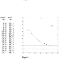
- a finite number of two-dimensional parameter sets can be calculated and stored, as in FIG Figure 1 shown, the boom length (or radius) is plotted on the abscissa and the maximum load capacity is plotted on the ordinate. From the drawn and precalculated limit curve z. B. read that the maximum load capacity for the boom length is 15 meters in about 30 tons.
- the limit curves for other functional elements or components of the superstructure are normally also two-dimensional and can be combined with the limit curves of the boom to form a two-dimensional set of parameters. So arise with z. B. a finite number n G of counterweights and n A boom lengths in total n A ⁇ n G two-dimensional parameter sets for the entire superstructure.
- Figure 2 shows the in Figure 1 Load curve already shown for the stability of the boom ALG, whereby the limit curves for the slewing ring DV, the luffing cylinder WZ and the superstructure OW (all shown by way of example over the radius of the boom) are also drawn in, which makes them comparable.
- the luffing cylinder curve can, for example, also be plotted over the luffing cylinder length. The connection between the length of the luffing cylinder and the radius can then be derived again from the condition of the crane.
- the lowest curve drawn as the load curve results, which, for. B. is determined up to a boom length of about 7 meters from the boom strength limit curve.
- the module load curve is determined by the limit curve of the slewing ring, since this allows lower values for the maximum load than the other limit curves in the range mentioned.
- the module load curve is defined by the luffing cylinder limit curve with the lowest permissible loads in this area.
- the limit curves for the components of the undercarriage can normally also be represented with a two-dimensional parameter set.
- the position of the uppercarriage relative to the undercarriage (angle of rotation) is excluded as a variable and a minimum value permissible for all positions is determined in advance.
- the superstructure parameter sets there are further possible combinations with the superstructure parameter sets. For example, with four support beams S1, S2, S3 and S4, there are n S1 ⁇ n S2 ⁇ n S3 ⁇ n S4 possible combinations with the superstructure parameter sets.
- a single parameter n S can exist in a large number of finite states or also in an infinite (stepless) number of states, so that a finite or infinite number of combinations results.
- the load capacity of a crane with at least two assemblies, each assembly being specified by at least one parameter, for example an operating parameter and / or a state parameter, is determined e.g. B. is determined by the fact that for at least a first assembly which has or has the lowest number of parameters or the lowest number of variation possibilities or the lowest gradient (the smallest change in the maximum load capacity when one or more status parameters change), the limit load or limit curve or the maximum payload is determined in advance and stored and the assigned value of the payload is read out for the current parameter or parameters, at least for a second module with the largest number of parameters or the largest number of possible variations or with the highest gradient (the greatest change in the maximum load when changing one or more status parameters) the limit load or maximum load is only determined if necessary.
- B. is determined by the fact that for at least a first assembly which has or has the lowest number of parameters or the lowest number of variation possibilities or the lowest gradient (the smallest change in the maximum load capacity when one or more status parameters change), the limit load or limit curve or the maximum payload is determined
- This needs-based determination is based on the current operating and / or state parameter combination and can e.g. B. by calculating and checking the calculation based on previously determined and stored values. For this, e.g. B. a formulaic relationship between the maximum load and the state parameters and / or operating parameters can be specified and stored as a calculation rule.
- a "first assembly" in the above sense can e.g. the superstructure including the boom and counterweight; a second assembly can e.g. Undercarriage with outriggers, uppercarriage and uppercarriage rotation angle.
- the determination of the load capacity or maximum load capacity of a crane is not only carried out exclusively on the basis of previously stored values.
- B. only used if it is easy to save limit curves, so z. B. two-dimensional limit curves or three-dimensional limit curves, in individual cases also one or more higher-dimensional limit curves and / or to check a calculation, z. B. for the undercarriage.
- z. B. two-dimensional limit curves or three-dimensional limit curves, in individual cases also one or more higher-dimensional limit curves and / or to check a calculation, z. B. for the undercarriage.
- the use of only low-dimensional limit curves according to the invention enables a simple partial solution to the problem of determining the overall load-bearing capacity of a crane.
- a calculation is carried out, which is based, for example, on one or more predefined formulaic relationships or formulas in order to use current parameter values or parameter combinations and taking account of the stored limit curves ascertained partial load capacities to determine a total load capacity, whereby, as already described, for safety reasons the lowest module-specific maximum load capacity is determined as the maximum load capacity of the crane.
- the assembly that can carry the lowest load in the present configuration determines the maximum permissible load of the crane.
- precalculated two- or three-dimensional limit curves or maximum module-related or module-specific loads for the boom system, and optionally also for the luffing cylinder, parameters that determine the current crane configuration can be read out and these precalculated limit curves or maximum module-related or module-specific load capacities can be transferred to the crane control become.
- the crane control z. B. on the basis of the detection of the current configuration of the boom system an assigned z. B. two-dimensional limit curve can be selected.
- the configuration of the boom system can e.g. B. can be recognized by entering a corresponding code or generally the corresponding configuration, for example by a user, and / or can also be recognized completely or additionally by one or more sensors.
- sensors can be arranged on a boom, which transmit the current length of the boom to the crane control.
- sensors can be arranged on a boom, which transmit the current length of the boom to the crane control.
- the relevant status and / or operating parameters are determined and based thereon the configuration or the parameters, for example, the two-dimensional limit curve for the superstructure is determined or from a memory be read out.
- the detection of the components or specific configuration can, as described above, by entering z. B. done by a user and / or by a sensor which is connected to the crane control or computing unit.
- the entry of parameters can also relate to the desired (later) states of the crane, which can currently have a different configuration. In this case, too, we speak of parameters that are actually present (eg entered).
- the maximum load capacity of the undercarriage can be determined on the basis of the detection of the configuration or of components, in particular the configuration or geometry of the support base of the undercarriage.
- the operating and / or status parameters used to describe the configuration of the undercarriage can e.g. B. entered and / or determined by sensors. Since the condition parameters of the undercarriage, e.g. four continuously and independently extendable and retractable support beams, in the example described not only can take on discretely predetermined values, but e.g. B. theoretically infinitely many values between two predetermined positions (z. B. fully retracted support beam and fully extended support beam) can assume due to a stepless adjustability and because several, z. B.
- the maximum load of the undercarriage is only calculated for the current configuration, whereby, unlike in the case of a pre-calculation and storage in a memory, it is not necessary to calculate and save all possible individual states or possible combinations of different individual states. This calculation can be checked using previously saved values.
- the calculated limit load or maximum payload can optionally also be determined taking into account the limit curve or payload determined as described above for the superstructure and boom system for a specific angle of rotation between the undercarriage and the superstructure.
- This calculation is optionally carried out for the entire turning range between undercarriage and uppercarriage, i.e. in the range from 0 degrees to 360 degrees, whereby this calculation can be carried out in advance or if necessary, for example also continuously, and can therefore specify a load curve dependent on the angle of rotation.
- this calculation can also be done in discrete steps and z. B. divided into continuous discrete steps, such as B. 1 degree increments or 5 degree increments, determine what the maximum load is for the rotational positions taken into account.
- a maximum load for any configuration of the support base and for any angle of rotation between the uppercarriage and undercarriage can be calculated based on a plurality of these calculations, e.g.
- a limit curve can be specified for the crane, and the maximum load for different angles of rotation of the superstructure relative to the undercarriage can be specified based on the individual calculations.
- the only variable parameter of this limit curve is then the angle of rotation, the undercarriage configuration is then assumed to be constant in the specific state.
- a new limit curve can also be calculated.
- B. the only parameter is the angle of rotation between the uppercarriage and the undercarriage. This makes it possible, on the one hand, to reduce the effort involved in the preliminary determination of limit curves and the storage required for the storage, and, on the other hand, to easily determine the total load-bearing capacity of a crane for a complete system with theoretically an infinite number of conditions or possible combinations, and thus to make optimum use of the total load-bearing capacity of the crane.
- the angle of rotation between undercarriage and superstructure can e.g. B. detected by a sensor and transmitted to the crane controller or a payload calculation unit to determine the maximum permissible payload for the currently available configuration.
- Figure 3 shows the working mode "360 degree table".
- the minimum load-bearing capacity from the entire turning range is taken as a basis. It is therefore not to be expected that a critical condition will arise during turning.
- the working speeds do not have to be limited separately.
- Figure 4 shows the work mode "Restricted work area".
- the work area is limited in advance to a certain area (e.g. 180 degrees to the rear).
- the minimum load capacity for the selected work area is taken as a basis.
- the switch-off limits for turning are known in advance and are independent of load capacity utilization. When approaching the work area limit, the speed is reduced in good time and the turning movement in front of or at the limit is stopped.
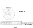
- Figure 5 shows the working mode "sector-related capacities".
- the work area is divided in advance into suitable sectors (e.g. 180 degrees left / right or 90 degrees above the supports).
- the minimum load-bearing capacity for the individual sectors is determined and taken as a basis.
- the switch-off limits for turning depend on the load capacity utilization and must be determined dynamically. A change in the permissible load can, however only come into play at the sector borders. Thus, the speed only has to be reduced separately when the sector boundaries are approached and the movement in front of or at the border may have to be stopped.
- Figure 6 shows the working mode "Optimized load capacity".
- the work area is divided into finite sectors (e.g. 5 degrees or 10 degrees) in advance.
- the optimum or maximum load-bearing capacity for this sector is used as a basis.
- the switch-off limits for turning depend on the load capacity utilization and are determined dynamically.
- the permissible load can be changed at any time. This means that the speed is constantly monitored and, depending on the permissible loads and the current utilization of the load capacity, can be adjusted separately and reduced if necessary. In the maximum case, the movement can be stopped in time.
- Figure 8 shows a crane which can carry out the method described above.
- a crane has a telescopic boom 1, the angle of attack of which can be adjusted by means of the luffing cylinder 2.
- support beams 3 are provided on the right and left, which can assume any intermediate position between a fully inserted position and a fully extended position.
- a counterweight 4 is provided, which can assume one of several predefined discrete values from different counterweights.
- Figure 9 shows the in Figure 8 Crane shown with the identification of sensors, which can be used individually or in combination to determine the configuration or state parameters or operating parameters of the crane.
- one or more sensors can be provided for determining the boom angle.
- a sensor can be provided for determining the boom length or boom telescoping.
- 9 designates the area in which a sensor for determining the luffing cylinder pressure and thus the operating state or the luffing cylinder configuration can be provided.
- One or more sensors for determining the support width can be provided at the points marked with 10 and sensors for determining the support pressure can be provided at the points marked with 11.
- a sensor for determining the counterweight denotes a sensor for determining the counterweight
- 13 a sensor for determining the rope force
- 14 a sensor for detecting additional equipment (for example a hose drum for supplying oil to the tip cylinder, a tip mounted on the boom).
- a sensor can optionally. B. can be provided to detect the actual load on the boom.
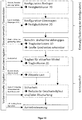
- Figure 10 shows a flow chart for calculating a payload volume.
- the configuration is first defined once, see the two steps above.
- the configuration of the boom and the configuration of the superstructure are determined and a strength curve or load curve is determined in each case, which can be two-dimensional or multi-dimensional.
- the state parameters of the boom are, for example, the angle, telescoping and tip (no conclusive list).
- the state parameters of the superstructure are, for example, the curve of the boom, the current counterweight and the state of the hoist (likewise no conclusive list).
- the undercarriage configuration can theoretically assume an infinite number of states due to the variable support width of the supports, whereby the load-bearing capacity is calculated for the specific condition, which is automatically determined, for example, using the sensors provided on the support supports to determine the respective extension state.
- a maximum load capacity dependent on the angle of rotation can be calculated.
- B. a three-dimensional payload volume can be created. Large gradients can also be recognized here. In this context, gradients can indicate, for example, how much the payload changes due to changes in parameters. These are very important for safe operation and can also be assessed separately.
- certain configurations e.g.
- the subsequent steps in operation can be carried out continuously or continuously. It can be used for the current angle of rotation between uppercarriage and undercarriage is determined, for example by means of a rotation angle sensor, the respectively permissible maximum load is determined. This then leads to the 2D payload curve load-over-radius, which represents the payload for different rocking angles (radii), for example.
- a calculation can be carried out to indicate to an operator that the speed is to be reduced or the crane is to be switched off in a safety mode.
- This information can also be automatically converted into the specified actions.
- the output value of a wind sensor and / or a support pressure limit and / or a user input can be taken into account.
- This information can be passed on to a drive control for operating the crane.
Landscapes
- Engineering & Computer Science (AREA)
- Mechanical Engineering (AREA)
- Physics & Mathematics (AREA)
- General Physics & Mathematics (AREA)
- Jib Cranes (AREA)
Description
Die Erfindung betrifft ein Verfahren zum sicheren Ermitteln der Tragfähigkeit eines Krans und zur Überwachung der Sicherheit eines Krans sowie einen Kran, welcher diese Verfahren ausführen kann und z.B. eine variable Abstützbasis aufweisen kann. Weiterhin betrifft die Erfindung die Berechnung einer dreidimensionalen Arbeitskurve und die Ermittlung der zulässigen Geschwindigkeiten bei der Bewegung von Funktionselementen des Krans.The invention relates to a method for safely determining the load capacity of a crane and for monitoring the safety of a crane, as well as a crane which can carry out these methods and e.g. can have a variable support base. Furthermore, the invention relates to the calculation of a three-dimensional working curve and the determination of the permissible speeds during the movement of functional elements of the crane.
Die Tragfähigkeit eines Kranes setzt sich aus mehreren baugruppenbedingten Einzeltragfähigkeiten oder Grenzbelastungen verschiedener Kranbauteile oder Kranbaugruppen zusammen. Einige Grenzbelastungen lassen sich relativ einfach anhand weniger Parameter ermitteln oder sind für eine Anzahl von Zuständen konstant, andere Grenzbelastungen werden von einer Vielzahl von Parametern beeinflusst und lassen sich häufig nur schwer im Voraus ermitteln. Die einfach zu ermittelnden Grenzbelastungen oder Grenzkurven hängen häufig nur von einem einzigen Parameter ab und können zum Beispiel als zweidimensionale Grenzkurve vorab ermittelt und in einem Speicher abgelegt werden. Auf diesen Speicher kann bei Bedarf zugegriffen werden und für den jeweils aktuell oder konkret vorliegenden Parameter kann aus dem Speicher die zugeordnete vorab berechnete maximale Traglast ausgelesen werden.The load-bearing capacity of a crane is made up of several individual load-bearing capacities that are related to the assembly or limit loads of different crane components or crane assemblies. Some limit loads can be determined relatively easily using a few parameters or are constant for a number of states, other limit loads are influenced by a large number of parameters and are often difficult to determine in advance. The easy-to-determine limit loads or limit curves often only depend on a single parameter and can, for example, be determined in advance as a two-dimensional limit curve and stored in a memory. This memory can be accessed if required and the assigned previously calculated maximum load can be read from the memory for the currently or specifically available parameter.
Jedoch ist es bei einer größeren Anzahl von Kranbaugruppen, welche zum Teil unabhängig voneinander verschiedene Zustände annehmen oder konfiguriert werden können, problematisch, Grenzkurven oder allgemein baugruppenbedingte Belastungshöchstgrenzen für den Gesamtkran anzugeben, welcher auf eine Vielzahl von Arten konfiguriert werden kann. Hat eine erste Baugruppe beispielsweise n1 Konfigurationsmöglichkeiten, eine zweite Baugruppe n2 Konfigurationsmöglichkeiten und eine dritte Baugruppe n3 Konfigurationsmöglichkeiten, so ergeben sich insgesamt n1∗n2∗n3 Gesamtkonfigurationen des Kranes. Falls eine der Konfigurationsmöglichkeiten nicht als eine diskrete Anzahl unterschiedlicher Zustände sondern zum Beispiel stufenlos realisierbar ist, zum Beispiel durch die stufenlose Ausfahrbarkeit eines oder aller Stützträger, ergeben sich theoretisch unendlich viele Krankonfigurationen, wobei es dann unmöglich ist vorab für alle möglichen Kranzustände eine Gesamttragfähigkeit des Kranes für den jeweiligen konkreten Konfigurationszustand anzugeben. Selbst für die Stützträger-Baugruppe allein kann keine baugruppenbedingte Tragfähigkeit für alle möglichen Konfigurationen vorab bestimmt und gespeichert werden.However, in the case of a larger number of crane assemblies, which in some cases assume different states independently of one another or can be configured, it is problematic to specify limit curves or maximum assembly-related load limits for the entire crane, which can be configured in a variety of ways. For example, if a first assembly has n1 configuration options, a second assembly has n2 configuration options, and a third assembly has n3 configuration options, the overall configurations of the crane are n1 ∗ n2 ∗ n3. If one of the configuration options cannot be realized as a discrete number of different states but, for example, continuously, for example due to the stepless extension of one or all support beams, there are theoretically an infinite number of crane configurations, whereby it is then impossible for the crane to have a total load capacity for all possible crane states to be specified for the respective specific configuration state. Even for the support bracket assembly alone, no assembly-related load-bearing capacity can be determined and saved in advance for all possible configurations.
Zwar könnte für einzelne Kranbaugruppen ein Sicherheitsarbeitsbereich angegeben werden, welcher für bestimmte diskrete Zustände die Tragfähigkeit spezifiziert, wobei zum Beispiel bei einer stufenlos verstellbaren Kranbaugruppe der Ist-Zustand ermittelt wird und zum Beispiel durch Interpolation zwischen benachbarten Stützstellen eine Tragfähigkeit ermittelt wird. Jedoch wird bei dieser Vorgehensweise möglicherweise eine zu geringe Traglast ermittelt und somit die Einsetzbarkeit des Kranes zu stark eingeschränkt.A safety work area could be specified for individual crane assemblies, which specifies the load-bearing capacity for certain discrete conditions, whereby the actual condition is determined for a continuously adjustable crane assembly, for example, and a load-bearing capacity is determined by interpolation between neighboring support points. However, this approach may result in a too low load capacity, thus limiting the crane's usability too much.
Die Sicherheit eines Krans wird mittels einer Kransteuerung während des Kranbetriebes überwacht. Die Kransicherheit ist dann gewährleistet, wenn verschiedene vorgegebene Sicherheitskriterien eingehalten werden. Mögliche Sicherheitskriterien sind zum Beispiel die Bauteilfestigkeit oder Tragfähigkeit von Kransystemen, wie zum Beispiel Ausleger, Hubseil, Lasthaken, Drehkranz- und Wippzylinder sowie die Standsicherheit des Krans, das heißt die Vermeidung eines Krankippens, zum Beispiel bedingt durch die Last, Wind, einen bestimmten Oberwagendrehwinkel usw.The safety of a crane is monitored by a crane controller during crane operation. Crane safety is guaranteed if various specified safety criteria are met. Possible safety criteria are, for example, the component strength or load-bearing capacity of crane systems, such as jibs, hoisting ropes, load hooks, slewing ring and luffing cylinders, as well as the stability of the crane, i.e. the avoidance of crane tipping, for example due to the load, wind, and a certain superstructure angle etc.
Die
Die
Die
Die
Es ist eine Aufgabe der vorliegenden Erfindung ein Verfahren zum Ermitteln der Tragfähigkeit eines Krans mit mindestens zwei Baugruppen vorzuschlagen.It is an object of the present invention to propose a method for determining the load capacity of a crane with at least two assemblies.
Diese Aufgabe wird durch die Gegenstände der unabhängigen Ansprüche gelöst. Weitere vorteilhafte Ausbildungen sind in den abhängigen Ansprüchen definiert.This object is solved by the subject matter of the independent claims. Further advantageous developments are defined in the dependent claims.
Ein Funktionselement ist eine funktionale Einheit eines Krans, welche eine bestimmte Funktion ausführen kann, wie z.B. Ausleger, Hubwerk, Wippzylinder, Stützträger oder Gegengewicht. Der Zustand eines Funktionselements kann durch mindestens einen Parameter beschrieben oder definiert werden. Es ist möglich, dass ein Funktionselement verschiedene Zustände hat (z.B. ein variabler Ausleger hat zwei Zustandsparameter: Länge und Auslegerwinkel; ein Stützträger hat den Zustandsparameter Ausfahrlänge oder Stützbreite), welche die Konfiguration, also z.B. die Geometrie, z.B. Länge oder Drehwinkel, des Funktionselements definieren. Üblicherweise wird ein Kran vor Inbetriebnahme konfiguriert, so dass die Zustandsparameter der Funktionselemente festgelegt werden. Während eines Hebevorgangs findet dann gewöhnlich keine Umkonfiguration mehr statt, d.h. die Zustandsparameter bleiben konstant.A functional element is a functional unit of a crane that can perform a specific function, such as a boom, hoist, luffing cylinder, support bracket or counterweight. The state of a functional element can be described or defined by at least one parameter. It is possible that a functional element has different states (e.g. a variable boom has two status parameters: length and boom angle; a support beam has the status parameter extension length or support width), which define the configuration, e.g. the geometry, e.g. length or angle of rotation, of the functional element . Usually a crane is configured before commissioning, so that the state parameters of the functional elements are determined. No reconfiguration usually takes place during a lifting process, ie the state parameters remain constant.
Jedoch können einzelne Funktionselemente auch im Betrieb, also z.B. während des Hebens der Last, verschiedene durch Betriebsparameter (zu unterscheiden von Zustandsparameter) definierte Zustände annehmen (z.B. Betriebsparameter des Hubwerks: Hubhöhe; Betriebsparameter eines Stützträgers: Stützdruck; Betriebsparameter des Auslegers: Auslegerwinkel oder Spitzenwinkel).However, individual functional elements can also assume various states during operation, e.g. while lifting the load (e.g. operating parameters to be distinguished from state parameters) (e.g. operating parameters of the hoist: lifting height; operating parameters of a support beam: support pressure; operating parameters of the boom: boom angle or tip angle) .
Ein Funktionselement kann eine bestimmte oder spezifische Festigkeit aufweisen, welche angibt bis zu welcher Belastung (gemessen z.B. in Tonnen Hubgewicht) das Funktionselement fest, also z.B. versagensfrei oder betriebssicher ist.A functional element can have a certain or specific strength , which indicates up to which load (measured, for example, in tons of lifting weight) the functional element is solid, that is to say, for example, free of failure or reliable.
Ein Funktionselement kann eine bestimmte oder spezifische Stabilität aufweisen, welche angibt bis zu welcher Belastung (gemessen z.B. in Tonnen Hubgewicht) das Funktionselement stabil steht, also z.B. nicht kippt oder zu einem Kippen des Krans führt.A functional element can have a certain or specific stability , which indicates up to which load (measured, for example, in tons of lifting weight) the functional element is stable, that is, for example, does not tip over or lead to the crane tipping over.
Dabei können Festigkeit und Stabilität von der Konfiguration des Funktionselements (also z. B. von dessen Zustandsparametern) und/oder auch von dessen Betriebsparametern abhängen, so dass sich bei unterschiedlichen Konfigurationen und/oder verschiedenen Betriebszuständen unterschiedliche zulässige Belastungen ergeben.Strength and stability can depend on the configuration of the functional element (i.e., for example, on its state parameters) and / or also on its operating parameters, so that different permissible loads result in different configurations and / or different operating states.
Da ein Funktionselement den Anforderungen sowohl an die Festigkeit als auch an die Stabilität genügen muss, kann die Tragfähigkeit unter Berücksichtigung beider Kriterien ermittelt werden. Üblicherweise wird von der maximalen Tragfähigkeit unter Berücksichtigung der Festigkeit und der maximalen Tragfähigkeit unter Berücksichtigung der Stabilität die geringere maximale Tragfähigkeit als zulässige Traglast gewählt. Optional kann auch nur die Tragfähigkeit unter Berücksichtigung der Festigkeit ermittelt werden. Die Stabilität kann im Hinblick auf den Kran als Ganzes, also zusammengesetzt aus den einzelnen Funktionselementen, überwacht werden.Since a functional element must meet the requirements for both strength and stability, the load-bearing capacity can be determined taking both criteria into account. Usually, the lower maximum load capacity than the permissible load capacity is selected from the maximum load capacity taking into account the strength and the maximum load capacity taking the stability into account. Optionally, only the load-bearing capacity can be determined taking into account the strength. The stability can be monitored with regard to the crane as a whole, i.e. composed of the individual functional elements.
Im Falle nur eines einzigen Zustandsparameters des Funktionselements kann z.B. die Tragfähigkeit oder maximale Traglast über den Zustandsparameter aufgetragen werden. Dies kann auch als zweidimensionale Grenzkurve (oder Grenzbelastung bzw. Gültigkeitsbereich) bezeichnet werden. Bei drei oder mehr Zustandsparametern des Funktionselements können sich auch drei- oder mehrdimensionale Grenzkurven bzw. Grenzflächen ergeben.In the case of only a single status parameter of the functional element, e.g. the load-bearing capacity or maximum load-bearing capacity are plotted over the condition parameter. This can also be called a two-dimensional limit curve (or limit load or scope). With three or more state parameters of the functional element, three-dimensional or multi-dimensional boundary curves or interfaces can also result.
Eine Baugruppe beinhaltet mindestens ein Funktionselement, kann aber auch aus zwei oder mehr Funktionselementen zusammengesetzt sein.An assembly contains at least one functional element, but can also be composed of two or more functional elements.
Übliche Baugruppen eines Krans sind: Ausleger oder Teile des Auslegers wie Hauptausleger, Spitzenverlängerung, Gesamtausleger; Oberwagen oder Teile des Oberwagens wie Gegengewicht, auch unter Berücksichtigung der Position, Hubwerk, Drehverbindung, Wippzylinder, Unterwagen oder Teile des Unterwagens wie Abstützungen, Fahrwerksrahmen, Schwerpunkte, Rüstzustände etc.Common assemblies of a crane are: boom or parts of the boom such as main boom, jib extension, overall boom; Superstructure or parts of the superstructure such as counterweight, also taking into account the position, hoist, slewing ring, Luffing cylinders, undercarriages or parts of the undercarriage such as supports, chassis frames, focal points, set-up conditions etc.
Eine Baugruppe hat ebenso wie die Funktionselemente eine Grenzkurve, welche sich aus den einzelnen baugruppenbedingten Grenzkurven oder Tragfähigkeiten der Baugruppenbestandteile ergibt. Als zulässige Traglast wird z. B. die geringste maximale Traglast der jeweiligen Baugruppenbestandteile gewählt.Like the functional elements, an assembly has a limit curve, which results from the individual module-related limit curves or load capacities of the component parts. As a permissible load z. B. selected the lowest maximum load of the respective assembly components.
Eine Baugruppe kann z.B. aus mehreren Funktionselementen zusammengesetzt sein, wie z.B. der Oberwagen bestehend aus Wippzylinder, Hubwerk, Gegengewicht und Ölvolumen. Das Ölvolumen kann je nach Betriebszustand, z.B. Stellungen der Hydraulikzylinder, sehr stark schwanken und kann damit das Oberwagengewicht und damit den Gesamtschwerpunkt des Krans beeinflussen. Dies kann als Parameter für die Stand- bzw. Kippsicherheit relevant sein Eine weitere Baugruppe kann der Unterwagen bestehend aus z.B. vier oder mehr Stützträgern sein, welche verschiedene gleiche oder voneinander unabhängig auch variable oder verschiedene Ausfahrlängen, Festigkeiten und Stützkraftgrenzen aufweisen können.An assembly can e.g. be composed of several functional elements, e.g. the uppercarriage consisting of luffing cylinder, hoist, counterweight and oil volume. The oil volume can vary depending on the operating state, e.g. The positions of the hydraulic cylinders fluctuate greatly and can influence the superstructure weight and thus the overall center of gravity of the crane. This can be relevant as a parameter for stability or tipping safety. The undercarriage consisting of e.g. four or more support beams, which can have different identical or independently of one another also variable or different extension lengths, strengths and supporting force limits.
Beispielsweise kann folgende Zuordnung vorgenommen werden:
- Baugruppe Ausleger :
Funktionselemente: Teleskopteile, Telezylinder, Spitzenverlängerungen, Abspannvorrichtungen - Baugruppe Oberwagen:
Funktionselemente: Drehtisch (Stahlbau), Wippzylinder, Hubwerk, Drehverbindung, Gegengewicht - Baugruppe Unterwagen:
Funktionselemente: Fahrwerksrahmen, Abstützträger, Abstützzylinder, Bereifung
- Boom assembly:
Functional elements: telescopic parts, telescopic cylinders, tip extensions, guy devices - Upper carriage assembly:
Functional elements: turntable (steel structure), luffing cylinder, hoist, slewing ring, counterweight - Undercarriage assembly:
Functional elements: chassis frame, support bracket, support cylinder, tires
Eine Grenzbelastung oder Grenzkurve, auch Traglastkurve, gibt für ein Funktionselement, eine Baugruppe, oder einen Kran an, welche maximale Traglast in welcher Konfiguration, also z. B. abhängig von den Werten der Zustandsparameter und optional auch der Betriebsparameter, gehoben werden kann oder gehoben werden darf.A limit load or limit curve, also the load curve, indicates for a functional element, an assembly or a crane what maximum load capacity in which configuration, e.g. B. depending on the values of the state parameters and optionally also the operating parameters, can be raised or may be raised.
Eine oder mehrere Grenzbelastungen oder Grenzkurven können in einem Speicher gespeichert sein, auf welchen vor, bei oder nach der Konfiguration des Krans für die konkrete aktuelle Konfiguration des Kranes zugegriffen wird, um die Traglasten der Funktionselemente oder Baugruppen des Krans und/oder für den gesamten Kran auszulesen oder zu ermitteln.One or more limit loads or limit curves can be stored in a memory, which is accessed before, during or after the configuration of the crane for the specific current configuration of the crane, the load capacities of the functional elements or assemblies of the crane and / or for the entire crane read out or determine.
Grenzbelastungen oder Grenzkurven können auch als eine Anzahl von diskreten Werten abgespeichert werden, wobei die Traglasten für die jeweilige konkrete Konfiguration bei Bedarf auch durch Interpolation oder Extrapolation gespeicherter Werte ermittelt werden können, wie zum Beispiel in der
Grenzbelastungen oder Grenzkurven können auch zum Teil oder vollständig durch einen oder mehrere formelmäßige Zusammenhänge angegeben und vorab oder bei Bedarf errechnet werden und falls erforderlich durch abgespeicherte Grenzbelastungen oder Grenzkurven ergänzt werden.Limit loads or limit curves can also be specified in part or in full using one or more formulaic relationships and can be calculated in advance or as required and, if necessary, supplemented by stored limit loads or limit curves.
Mittels Grenzbelastungen oder Grenzkurven kann die Gesamttragfähigkeit eines Krans in der jeweiligen Konfiguration ermittelt werden. Dabei können sich abhängig von den Betriebsparametern des Krans in unterschiedlichen Betriebszuständen eines Krans mit fester Konfiguration z. B. auch unterschiedliche Traglasten ergeben. Es ist auch möglich, dass bei einer vorgegebenen konstant bleibenden Konfiguration die Betriebsparameter keinen Einfluss auf die maximale Traglast eines Kranes haben.The total load-bearing capacity of a crane in the respective configuration can be determined using limit loads or limit curves. It can depend on the operating parameters of the crane in different operating states of a crane with a fixed configuration such. B. also result in different loads. It is also possible that with a given constant configuration, the operating parameters have no influence on the maximum load capacity of a crane.
Prinzipiell kann eine Traglastermittlung oder Tragfähigkeitsermittlung für einen Kran basierend auf einer Berechnung unter Verwendung einer aktuellen Konfiguration des Kranes oder aktuell vorliegenden Parametern für den konkreten Zustand des Kranes erfolgen.In principle, a load capacity determination or load capacity determination for a crane can be carried out based on a calculation using a current configuration of the crane or currently available parameters for the specific condition of the crane.
Alternativ oder ergänzend kann die Tragfähigkeit eines Kranes basierend auf einem oder mehreren vorher ermittelten oder berechneten und abgespeicherten Tragfähigkeitswerten oder Tragfähigkeitswerten einer oder mehrerer Funktionselemente oder Baugruppen ermittelt werden. Weiterhin ist es möglich, eine Kombination beider Verfahren anzuwenden, also die Tragfähigkeit eines Kranes basierend auf vorher abgespeicherten Werten sowie basierend auf einer Berechnung, wie z.B. einer Tragfähigkeitsberechnung basierend auf einem formelmäßigen Zusammenhang oder auch einer Interpolations- oder Extrapolationsberechnung, zu ermitteln.As an alternative or in addition, the load capacity of a crane can be determined based on one or more previously determined or calculated and stored load capacity values or load capacity values of one or more functional elements or assemblies. It is also possible to use a combination of both methods, i.e. the load capacity of a crane based on previously stored values and based on a calculation, such as a load capacity calculation based on a formula-based relationship or an interpolation or extrapolation calculation.
Beispielsweise können für einen Ausleger, wie einen Hauptausleger, ausgebildet z. B. als Teleskopausleger, Traglasten oder Auslegergrenzkurven für jeden Teleskopierzustand vorab ermittelt und gespeichert werden. Die Speicherung kann beispielsweise in Gestalt einer Zuordnung einer maximalen Traglast zu einem z.B. als kontinuierlichen Parameter vorgebbaren Radius erfolgen. Grafisch dargestellt ergibt sich eine Traglastkurve aufgetragen über den Radius. Eine solche Kurve kann z. B. für jeden Teleskopierzustand abgespeichert werden.For example, for a boom, such as a main boom, trained z. B. as a telescopic boom, payloads or boom limit curves for each telescopic condition can be determined and saved in advance. The storage can be, for example, in the form of an assignment of a maximum load to a e.g. Radius that can be specified as a continuous parameter. A load curve is plotted against the radius. Such a curve can e.g. B. can be saved for each telescopic state.
Werden beispielsweise fünf Teleskope zu je zwei Verbolzungslöchern im Ausleger vorgesehen, so ergeben sich für jedes Teleskop drei Positionen (ganz eingeschoben + zwei durch die Verbolzungslöcher definierte verschiedene Ausschubzustände), so dass insgesamt 35=243 Teleskopierzustände oder Hauptauslegerlängen oder unterschiedliche Konfigurationen möglich sind. Wird für jede dieser 243 Teleskopierungen eine Auslegergrenzkurve vorab ermittelt und gespeichert, so liegen insgesamt 243 Kurven im Speicher vor.If, for example, five telescopes with two bolting holes are provided in the boom, there are three positions for each telescope (fully inserted + two different extension states defined by the bolting holes), so that a total of 3 5 = 243 telescopic states or main boom lengths or different configurations are possible. If a boom limit curve is determined in advance and saved for each of these 243 telescopes, there are a total of 243 curves in the memory.
Formelmäßig lässt sich die Tragfähigkeit oder Traglast des Auslegers darstellen als: ![]()
![]()
Für das Gegengewicht GG können verschiedene Konfigurationen gespeichert werden, wobei beispielhaft von zehn verschiedenen Konfigurationen ausgegangen wird.Different configurations can be stored for the counterweight GG, whereby ten different configurations are assumed as an example.
Für den Oberwagen kann z.B. die Festigkeit für den Drehtisch selbst vorab ermittelt und gespeichert werden, z.B. in Abhängigkeit von Ausleger und Gegengewicht GG. Formelmäßig lässt sich dies darstellen als: ![]()
![]()
Festigkeit und Gesamtschwerpunkt des Oberwagens sind abhängig von Ausleger, Gegengewicht und Drehtisch, was formelmäßig dargestellt werden kann wie folgt: ![]()
![]()
Durch die Parameter Teleskopierung (im oben spezifizierten Beispiel 243 Kurven) und Gegengewicht (10 verschiedene Konfigurationen gemäß Beispiel) ergeben sich theoretisch 2430 Kurven. Die aktuelle Oberwagengrenzkurve wird berechnet.The parameters telescopic (243 curves in the example specified above) and counterweight (10 different configurations according to the example) theoretically result in 2430 curves. The current upper carriage limit curve is calculated.
Die Drehverbindung kann eine gespeicherte Grenzkurve aufweisen und kann die Oberwagenlast gegebenenfalls reduzieren: ![]()
![]()
Dies hat jedoch keinen Einfluss auf die Anzahl der abgespeicherten Kurven, welche im angegebenen Beispiel bei 2430 verbleibt.However, this has no influence on the number of saved curves, which remains at 2430 in the given example.
Ein Unterwagen weist n Abstützungen auf (typischerweise vier, optional auch weniger oder mehr, z. B. sechs oder acht Abstützungen), welche in Gestalt eines Abstützkastens und Abstützzylinders ausgebildet sein können. Jede der n Abstützungen weist eine Grenzkurve auf, welche von der Konfiguration, also beispielsweise der Ausfahrlänge, der Abstützung abhängt: ![]()
![]()
Die Unterwagenkonfiguration kann somit durch n Parameter, also beispielsweise n = 4 Parameter, spezifiziert werden.The undercarriage configuration can thus be specified by n parameters, for example n = 4 parameters.
Jede der n Abstützungen kann z.B. 3 diskrete Ausfahrlängen aufweisen wodurch sich 34 = 81 unterschiedliche Kombinationen ergeben würden. Hier gibt es dann also 2430 x 81 = 196830 Möglichkeiten.Each of the n supports can have, for example, 3 discrete extension lengths, which would result in 3 4 = 81 different combinations. So there are 2430 x 81 = 196830 possibilities.
Um zu vermeiden, dass eine so große Anzahl an Kurven gespeichert werden muss, könnte z.B. nur eine vorgegebene und begrenzte Anzahl n an grundlegenden Abstützkonfigurationen, wie z.B. nur drei Abstützkonfigurationen, berücksichtigt und gespeichert werden, wie z.B. alle Stützen 0 % ausgefahren (1. Abstützkonfiguration), alle Stützen 50% ausgefahren (2. Abstützkonfiguration) und alle Stützen 100% ausgefahren (3. Abstützkonfiguration). Hier gibt es dann weniger (im angegebenen Beispiel: n = 3) Möglichkeiten, also 2430 x 3 = 7290 Möglichkeiten.To avoid having to save such a large number of curves, e.g. only a predetermined and limited number n of basic support configurations, e.g. only three support configurations are taken into account and saved, e.g. all supports extended 0% (1st support configuration), all supports extended 50% (2nd support configuration) and all supports extended 100% (3rd support configuration). There are then fewer (in the example given: n = 3) options, i.e. 2430 x 3 = 7290 options.
Zusätzlich enthält der Unterwagen den Parameter Drehwinkel (Oberwagendrehung relativ zum Unterwagen). Der Drehwinkel ist kontinuierlich verstellbar. Wenn für einen Rundumdrehwinkel von 360Grad eine Winkelauflösung von 1Grad gewählt wird, ergeben sich 360 Möglichkeiten. Sollen die im Ausführungsbeispiel oben beispielhaft erwähnten 2430 Kurven für eine Winkelauflösung von 1Grad abgespeichert werden, so ergeben sich insgesamt 360 x 2430 x 3 = 2624400 Kurven für n= 3 Abstützkonfigurationen. Die Speicherung einer so großen Anzahl an Kurven ist jedoch aus technischen Gründen problematisch und nicht praktikabel.The undercarriage also contains the parameter rotation angle (upper carriage rotation relative to the undercarriage). The angle of rotation is continuously adjustable. If an angular resolution of 1 degree is selected for an all-round rotation angle of 360 degrees, there are 360 possibilities. If the 2430 curves mentioned by way of example in the exemplary embodiment above are to be stored for an angular resolution of 1 degree, this results in a total of 360 x 2430 x 3 = 2624400 curves for n = 3 support configurations. However, storing such a large number of curves is problematic and not practical for technical reasons.
Alternativ oder ergänzend kann z.B. ein voller 360Grad-Drehbereich berücksichtigt werden, wobei eine maximale Traglast dann so angegeben wird, dass diese über den vollen 360Grad-Drehbereich getragen werden kann. Dabei ist dann derjenige Drehwinkel mit der kleinsten maximalen Traglast maßgeblich, d.h. es wird eine maximale Traglast für diejenigen Drehwinkel verschenkt, welche prinzipiell mehr Traglast aufnehmen könnten.Alternatively or in addition, e.g. a full 360 degree rotation range are taken into account, whereby a maximum load is then specified so that it can be carried over the full 360 degree rotation range. The angle of rotation with the smallest maximum load is decisive, i.e. a maximum load is given away for those angles of rotation that could in principle take up more load.
Alternativ kann der 360Grad-Drehbereich auch unterteilt werden und es können vorgegebene Drehwinkelabschnitte definiert werden, für welche eine erlaubte maximale Traglast konstant ermittelt und vorgegeben werden kann. Beispielsweise können m gleichgroße oder auch unterschiedlich große Bereiche vorgegeben werden, wie z.B. m = 4 Bereiche zu je 90Grad. Mit n Abstützkonfigurationen und einer Bereichsunterteilung in m Bereiche erhält man n x m x (mögliche Teleskopierzustände) x (mögliche Gegengewichtskonfigurationen) abzuspeichernde Kurven, also für die oben angegebenen Beispiele 3 x 4 x 2430 = 29160 Kurven. Hierdurch kann die oben angegeben Anzahl von 2624400 Kurven zwar deutlich reduziert werden, jedoch kann in der Praxis auch die Ermittlung und Speicherung einer solch großen Anzahl an Kurven technisch schwierig oder problematisch sein, insbesondere wenn z.B. ein Ausleger mehr Verbolzungslöcher aufweist und/oder im Betrieb verschiedene Spitzen verwendet werden. Gemäß einer Ausführungsform der Erfindung wird zur Ermittlung der Tragfähigkeit eines Kranes sowohl eine Berechnung vorgenommen als auch auf vorab gespeicherte Werte, wie z.B. vorab gespeicherte Tragfähigkeitswerte von Funktionselementen und/oder Baugruppen zugegriffen.Alternatively, the 360-degree rotation range can also be subdivided and predefined rotation angle sections can be defined for which a permissible maximum load can be constantly determined and specified. For example, m areas of the same size or of different sizes can be specified, such as m = 4 areas of 90 degrees each. With n support configurations and an area subdivision into m areas, you get nxmx (possible telescopic states) x (possible counterweight configurations) curves to be saved, i.e. 3 x 4 x 2430 = 29160 curves for the examples given above. As a result, the above-mentioned number of 2624400 curves can be significantly reduced, but in practice the determination and storage of such a large number of curves can be technically difficult or problematic, especially if, for example, a boom has more bolt holes and / or different ones during operation Tips are used. According to one embodiment of the invention, in order to determine the load capacity of a crane, a calculation is carried out and previously stored values, such as, for example, previously stored load capacity values of functional elements and / or assemblies are accessed.
Unter einer Berechnung kann im Sinne der vorliegenden Erfindung verstanden werden, dass z.B. ein formelmäßiger Zusammenhang bekannt ist, mittels dessen für konkret vorliegende Zustandsparameter und/oder Betriebsparameter eines Funktionselements und/oder einer Baugruppe ermittelt oder berechnet werden kann, wie groß die maximale Tragfähigkeit ist.A calculation can be understood in the sense of the present invention that e.g. a formal connection is known, by means of which the maximum load-bearing capacity can be determined or calculated for the concrete state parameters and / or operating parameters of a functional element and / or an assembly.
Gemäß einer Ausführungsform der Erfindung können auf der Basis von vorab ermittelten und abgespeicherten Werten Referenzdaten oder Überprüfungsdaten zur Überprüfung oder Kontrolle herangezogen werden, um zu ermitteln, ob die ermittelte maximale Traglast auch z.B. plausibel ist, so dass das errechnete Ergebnis validiert oder überprüft werden kann.According to one embodiment of the invention, reference data or verification data can be used for checking or checking on the basis of previously determined and stored values in order to determine whether the determined maximum load capacity is also e.g. is plausible so that the calculated result can be validated or checked.
Beispielsweise können zur Überprüfung einer Berechnung ausgewählte Traglast-Kurven abgespeichert werden, wie z.B.:
- Traglast für 360Grad, alle Stützen bei 100 % (vollständig ausgefahren): maximale Traglast (Beispiel): 10t
- Traglast für 360Grad, alle Stützen gleich, jedoch nur zu einem Teil ausgefahren (z.B. bei 80 %): maximale Traglast (Beispiel): 9t
- Optional weitere Traglasten für 360Grad, alle Stützen nur teilweise ausgefahren (beispielsweise bei 30 %, 50%...): maximale Traglast (Ausführungsbeispiel bei 50% ausgefahrenen Stützen): 6t
- Traglast für 360Grad, alle Stützen bei 0%: Traglast (Beispiel): 2t
- Payload for 360 degrees, all supports at 100% (fully extended): maximum payload (example): 10t
- Load capacity for 360 degrees, all supports are the same, but only partially extended (e.g. at 80%): maximum load (example): 9t
- Optional additional loads for 360 degrees, all supports only partially extended (e.g. at 30%, 50% ...): maximum load (exemplary embodiment with 50% extended supports): 6t
- Load capacity for 360 degrees, all supports at 0%: load capacity (example): 2t
Ergänzend können zusätzlich optional Referenztraglast-Punkte für vorgegebene Drehwinkel bei einem vorgegebenen Ausfahrzustand der Stützen abgespeichert werden. Werden als Drehwinkel diejenigen Winkel berücksichtigt, bei welchen der Ausleger über einer Stütze ist (also z.B.: 45Grad, 135Grad, 225Grad, 315Grad), so ergeben sich in der Regel hohe Traglasten, also Traglasten, welche in einzelnen Anwendungsfällen über den Rundum-Traglasten (Traglast für 360Grad) liegen können. Als Ausführungsbeispiel sei (für z. B. vollständig ausgefahrende Stützen, also 4 x 100%) angegeben:
- Traglast für 45Grad/135Grad/225Grad/315Grad: überall gleich 13t
- Load capacity for 45Grad / 135Grad / 225Grad / 315Grad: 13t everywhere
Für den gleichen Zustand der Stützen (also z.B. 4x100% ausgefahren) kann optional auch eine Traglast für die Zwischenzustände ermittelt werden, also z.B. eine Traglast für Drehwinkel 0Grad, 90Grad, 180Grad und 270Grad, bei welchen sich der Ausleger von oben betrachtet zwischen den Stützen befindet, so dass sich in der Regel eine niedrigere Traglast ergibt, als bei obigem Beispiel, wo der Ausleger über der Stütze ist.For the same state of the supports (e.g. 4x100% extended), a load for the intermediate states can optionally be determined, e.g. a load capacity for angles of
Als Ausführungsbeispiel wird für diese Zustände als maximale Traglast überall gleich 10t angegeben (als Minimum, wie 360° Rundumlast).As an exemplary embodiment, the maximum load is given as equal to 10 t for these conditions (as a minimum, such as 360 ° all-round load).
Allgemein können obige Traglastkurven oder Traglastwerte für einen oder mehrere vorgegebene Ausfahrzustände der Stützen (also z.B.: alle Stützen eingefahren, alle Stützen zum Teil ausgefahren, wie z.B. 10%, 20%, ..., 90%; und alle Stützen vollständig ausgefahren), als Rundum-Traglast (Traglast für 360Grad) und/oder auch für vorgegebene Sektoren oder einzelne Winkel oder Winkelbereiche (siehe vorheriges Beispiel: Ausleger über Stützen oder Ausleger zwischen Stützen) vorab ermittelt und abgespeichert werden.In general, the above load curves or load values for one or more specified extension states of the supports (e.g., all supports retracted, all supports partially extended, such as 10%, 20%, ..., 90%; and all supports fully extended), as an all-round payload (payload for 360 degrees) and / or also for specified sectors or individual angles or angular ranges (see previous example: boom over supports or boom between supports) can be determined and saved in advance.
Ergänzend zu obigem Beispiel können z.B. auch Referenztraglast-Punkte für nur teilweise ausgefahrene Stützen, z.B. 4 x 80%, ermittelt und wie folgt abgespeichert werden:
- Traglast für 45Grad/135Grad/225Grad/315Grad (Ausleger über Stütze): überall gleich 11t
- Traglast für 90Grad/270Grad (Ausleger zwischen Stützen): Traglast überall 9t (Minimum, Rundumlast)
- Traglast für 0Grad/180Grad (Ausleger zwischen Stützen): Traglast überall 10t
- Load capacity for 45Grad / 135Grad / 225Grad / 315Grad (boom over support): 11t everywhere
- Payload for 90Grad / 270Grad (boom between supports): payload everywhere 9t (minimum, all-round load)
- Load capacity for 0Grad / 180Grad (boom between supports): load capacity everywhere 10t
Die Vorab-Ermittlung und Abspeicherung von Referenztraglastpunkten für ausgewählte Zustände wird erfindungsgemäß nicht zur Ermittlung der Traglast verwendet (wäre jedoch möglich, wenn z.B. einer der dort exakt spezifizierten Zustände vorliegt). Stattdessen werden diese vorab gespeicherten Werte oder Kurven zur Überprüfung einer Berechnung verwendet. Die erfindungsgemäße Traglastermittlung erfolgt somit nicht durch Interpolation oder Extrapolation auf der Basis vorab gespeicherter Werte, sondern stattdessen durch eine Berechnung, wobei eine Überprüfung oder Validierung eines oder mehrerer berechneter Traglastwerte anhand von vorher abgespeicherten Referenzdaten erfolgt. Die Referenzdaten haben somit keine Auswirkung und keinen Einfluss auf einen ermittelten Zahlenwert für eine maximale Traglast, sondern werden lediglich verwendet, um den ermittelten Zahlenwert zu überprüfen, also für gültig und verwendbar zu erklären oder für ungültig zu erklären. In diesem Fall kann z. B. ein Warnsignal ausgegeben und/oder der Kran automatisch abgeschaltet oder angehalten werden.The preliminary determination and storage of reference load points for selected states is not used according to the invention to determine the load (but would be possible if, for example, one of the states exactly specified there is present). Instead, these previously saved values or curves are used to check a calculation. The load capacity determination according to the invention is therefore not carried out by interpolation or extrapolation on the basis of previously stored values, but instead by means of a calculation, with a check or validation of one or more calculated load capacity values taking place on the basis of previously stored reference data. The reference data therefore have no effect and no influence on a determined numerical value for a maximum load, but are only used to check the determined numerical value, i.e. to declare it valid and usable or to declare it invalid. In this case, e.g. B. issued a warning signal and / or the crane is automatically switched off or stopped.
Bei einer aktuellen Krankonfiguration sind alle Abstützungen vollständig ausgefahren (4x100%). Der Drehwinkel (Oberwagen relativ zu Unterwagen) beträgt 35Grad.With a current crane configuration, all outriggers are fully extended (4x100%). The angle of rotation (superstructure relative to undercarriage) is 35 degrees.
Eine Berechnung anhand einer vorgegebenen Formel liefert eine maximale Traglast von 12,5t.A calculation based on a given formula provides a maximum load of 12.5 t.
Erfindungsgemäß wird zur Überprüfung des berechneten Wertes von 12,5t auf vorab gespeicherte Referenzwerte wie beispielhaft oben angegeben zurückgegriffen. Dabei wird zur Überprüfung auf einen oder mehrere vorab abgespeicherte Datensätze zurückgegriffen, welche z.B. möglichst nah an der aktuellen Konfiguration liegen, wobei also z.B. einzelne Parameterwerte übereinstimmen oder einen geringen oder geringsten Abstand zu vorliegenden Parameterwerten aufweisen. Dabei können auch solche Datensätze verwendet werden, welche zu einem vorgegebenen Parameterwert einen geringsten Abstand nach oben und/oder nach unten (also nächstgrößerer und/oder nächstkleinerer abgespeicherter Wert) aufweisen. Dabei können ein oder mehrere Referenzwerte oder Vergleichswerte ermittelt werden, welche zur Überprüfung der berechneten maximalen Traglast herangezogen werden können.According to the invention, reference values stored in advance are used to check the calculated value of 12.5 t, as indicated above by way of example. One or more pre-stored data records are used for checking, e.g. as close as possible to the current configuration, e.g. individual parameter values match or are at a slight or minimal distance from existing parameter values. In this case, it is also possible to use data records which are at a minimal distance upwards and / or downwards from a predetermined parameter value (that is to say the next larger and / or next smaller stored value). One or more reference values or comparison values can be determined, which can be used to check the calculated maximum load.
Für das oben angegebene Ausführungsbeispiel kann beispielsweise als erster Vergleichswert der Referenztraglastpunkt (Drehwinkel: 45Grad bei 4x100%) herangezogen werden, welcher im obigen Ausführungsbeispiel eine maximale Traglast von 13t aufweist.For the above-mentioned embodiment, the reference load point (angle of rotation: 45 degrees at 4x100%) can be used as the first comparison value, for example, which has a maximum load of 13 t in the above embodiment.
Ein zweiter nächstliegender vorab gespeicherter Wert liegt bei (Drehwinkel: 0Grad und 4x100%), welcher im obigen Ausführungsbeispiel mit einer geringeren Traglast von 10t abgespeichert wurde.A second closest previously stored value is included (angle of rotation: 0 degrees and 4x100%), which was saved in the above embodiment with a lower load capacity of 10 t.
Da bekannt ist, dass, wie oben erwähnt, eine maximale Traglast bei einem über einer Stütze liegenden Drehwinkel (also z.B. 45Grad) größer sein kann (Ausführungsbeispiel: 13t) als bei einem zwischen den Stützen liegenden Drehwinkel (0Grad), welche mit 10t angegeben ist, kann das Intervall zwischen 10t und 13t als Plausibilitätsintervall basierend auf den vorab gespeicherten Traglastwerten ermittelt und angegeben werden, um zu überprüfen, ob die berechnete maximale Traglast plausibel ist und somit validiert werden kann.Since it is known that, as mentioned above, a maximum load can be greater with an angle of rotation above a support (e.g. 45 degrees) (exemplary embodiment: 13 t) than with an angle of rotation between the supports (0 degrees), which is specified as 10 t , the interval between 10t and 13t can be determined and specified as a plausibility interval based on the previously stored payload values in order to check whether the calculated maximum payload is plausible and can therefore be validated.
Die ermittelte Traglast betrug im Ausführungsbeispiel 12,5t und liegt somit im angegebenen Intervall, so dass die berechnete Traglast als richtig angenommen wird.The determined payload was 12.5 t in the exemplary embodiment and is therefore within the specified interval, so that the calculated payload is assumed to be correct.
Falls die Berechnung einen Wert liefern würde, welcher außerhalb des Intervalls liegt, wird davon ausgegangen dass ein Fehler vorliegt und es kann z.B. ein Abschaltvorgang vorgenommen werden.If the calculation would provide a value that lies outside the interval, it is assumed that there is an error and e.g. a shutdown process can be carried out.
Die aktuelle Konfiguration betrage 4x80% Abstützung und 35Grad Drehwinkel.The current configuration is 4x80% support and 35 degrees of rotation.
Eine Berechnung liefert eine Traglast von 10,8t.A calculation provides a payload of 10.8t.
Zur Überprüfung dieser Berechnung können basierend auf obigem Beispiel folgende nächstliegende vorab gespeicherte Datensätze herangezogen werden:
- 4x80% (Stützen), Drehwinkel 45Grad: vorab gespeicherte maximale Traglast 11t
- 4x80% (Stützen), Drehwinkel 0Grad: vorab gespeicherte maximale Traglast 9t
- 4x80% (supports), angle of rotation 45 degrees: previously stored maximum load 11t
- 4x80% (supports), angle of
rotation 0 degrees: previously stored maximum load 9t
Die berechnete aktuelle Traglast von 10,8t liegt im Intervall zwischen 9t und 11t und wird somit als gültig betrachtet.The calculated current payload of 10.8t lies in the interval between 9t and 11t and is therefore considered valid.
Um eine verbesserte Überprüfung durchführen zu können, können auch Tendenzen oder Gradienten der Traglastwerte betrachtet werden. Dabei wird als Zusatzinformation z.B. berücksichtigt, dass eine Traglast im Normalfall umso größer ist, je weiter die Stützen ausgefahren sind und umso geringer ist, je weiter die Stützen eingefahren sind.In order to be able to carry out an improved check, trends or gradients of the load capacity values can also be considered. As additional information, e.g. takes into account that the load is normally greater the further the supports are extended and the lower the further the supports are lowered.
Es wird angemerkt, dass obiges Ausführungsbeispiel auch entsprechend bei anderen Parametern herangezogen werden kann, wobei als Information auch immer berücksichtigt werden kann, welches die stabilen Zustände (Zustände oder Konfigurationen oder Parameterwerte mit höherer Traglast) und welches die Zustände oder Parameterwerte mit niedrigerer Traglast sind, um Plausibilitätsbetrachtungen, wie obige Gradienten-Betrachtung, durchzuführen. Weiterhin wurden im obigen Ausführungsbeispiel Vergleichsintervalle nur beispielhaft angegeben, es können jedoch auch feiner oder gröber abgestufte Datensätze oder Vergleichsintervalle verwendet werden. Allgemein wird die Überprüfung der Sicherheit einer Berechnung größer, je feiner die Unterteilung der vorab gespeicherten Parameterwerte ist.It is noted that the above exemplary embodiment can also be used accordingly for other parameters, it also being possible to take into account as information which of the stable states (states or configurations or parameter values with a higher load capacity) and which are the states or parameter values with a lower load capacity, to carry out plausibility considerations, such as the gradient analysis above. Furthermore, in the above exemplary embodiment, comparison intervals were only given as examples, but finer or coarser graduated data sets or comparison intervals can also be used. In general, the security of a calculation becomes greater the finer the subdivision of the previously stored parameter values.
Somit kann erfindungsgemäß durch relativ einfache Formeln eine Berechnung durchgeführt werden. Diese Berechnung kann basierend auf vergleichsweise wenigen vorab gespeicherten Datensätzen überprüft und validiert werden.Thus, according to the invention, a calculation can be carried out using relatively simple formulas. This calculation can be checked and validated based on a comparatively small number of previously stored data sets.
Es ist also nicht mehr erforderlich, eine sehr große Vielzahl an Kurven vorab zu berechnen und abzuspeichern und diese Kurven direkt zu nutzen beziehungsweise zwischen diesen Kurven zu interpolieren. Stattdessen kann erfindungsgemäß die Anzahl der abgespeicherten Kurven stark verringert werden, da diese nicht zur eigentlichen Berechnung z. B. durch Interpolation, sondern nur zur Überprüfung einer Berechnung verwendet werden. Als ermittelte Traglast wird folglich auch nur die entsprechend erfindungsgemäß validierte Berechnung verwendet und nicht ein Wert, welcher z. B. aus einer Interpolation vorab gespeicherter Kurven erhalten wurde.It is therefore no longer necessary to calculate and save a very large number of curves in advance and to use these curves directly or to interpolate between these curves. Instead, the number of stored curves can be greatly reduced according to the invention, since these are not used for the actual calculation, eg. B. by interpolation, but only to check a calculation. Consequently, only the calculation validated according to the invention is used as the determined load and not a value which, for. B. was obtained from an interpolation of previously stored curves.
Die Erfindung wird anhand von Ausführungsbeispielen unter Bezugnahme auf die Figuren beschrieben. Es zeigen:
Figur 1- eine zweidimensionale Tragfähigkeitskurve eines Auslegers (Radius - Tragfähigkeit);
Figur 2- eine Grenzkurve des Oberwagens basierend auf den Grenzkurven Auslegerfestigkeit, Drehverbindung und Wippzylinder;
Figur 3- den Arbeitsmodus "360-Grad-Tabelle";
Figur 4- den Arbeitsmodus "Eingeschränkter Arbeitsbereich";
Figur 5- den Arbeitsmodus "Sektorenbezogene Tragfähigkeiten";
Figur 6- den Arbeitsmodus "Optimierte Tragfähigkeit";
- Figur 7
- eine Bedienungsanzeige zur Darstellung von Traglasten und Arbeitsbereichen;
Figur 8- einen Kran mit Funktionselementen;
- Figur 9
- Sensoren des Krans in
Figur 8 Figur 10- ein Ablaufdiagramm zur Berechnung Traglastvolumen.
- Figure 1
- a two-dimensional load capacity curve of a boom (radius - load capacity);
- Figure 2
- a limit curve of the superstructure based on the limit curves jib strength, slewing ring and luffing cylinder;
- Figure 3
- the working mode "360-degree table";
- Figure 4
- the work mode "restricted work area";
- Figure 5
- the working mode "sector-specific capacities";
- Figure 6
- the working mode "Optimized load capacity";
- Figure 7
- an operating display to show loads and work areas;
- Figure 8
- a crane with functional elements;
- Figure 9
- Sensors of the crane in
Figure 8 ; and - Figure 10
- a flow chart for calculating the payload volume.
Ein Auslegersystem kann z. B. eine Grenzkurve in Form eines zweidimensionalen Parametersatzes "Radius/Tragfähigkeit" und/oder "Auslegerwinkel/Tragfähigkeit" haben. Diese Daten können z. B. in vordefinierten Schrittweiten, wie z. B. 1,0 Meter für den Radius und 1,0 Grad für den Winkel, berechnet und gespeichert werden. Beispielsweise kann für eine endliche Anzahl von Auslegerlängen und/oder Teleskopierungen und optional Kombinationen mit Spitzenlängen eine endliche Anzahl von zweidimensionalen Parametersätzen berechnet und gespeichert werden, wie in
Die Grenzkurven für weitere Funktionselemente oder Bauteile des Oberwagens sind im Normalfall ebenfalls zweidimensional und können mit den Grenzkurven des Auslegers zu einem zweidimensionalen resultierenden Parametersatz kombiniert werden. So ergeben sich bei z. B. einer endlichen Anzahl nG von Gegengewichten und nA Auslegerlängen insgesamt nA ∗nG zweidimensionale Parametersätze für den gesamten Oberwagen.The limit curves for other functional elements or components of the superstructure are normally also two-dimensional and can be combined with the limit curves of the boom to form a two-dimensional set of parameters. So arise with z. B. a finite number n G of counterweights and n A boom lengths in total n A ∗ n G two-dimensional parameter sets for the entire superstructure.
Wie aus
Die in
Die Grenzkurven für die Bauteile des Unterwagens lassen sich im Normalfall ebenfalls mit einem zweidimensionalen Parametersatz darstellen. Dabei wird die Stellung des Oberwagens relativ zum Unterwagen (Drehwinkel) als Variable ausgeschlossen und ein für alle Stellungen zulässiger Minimalwert vorab ermittelt. Bei einer Vielzahl von Kombination einzelner Parameter, insbesondere der Ausfahrlänge der Stützträger, ergeben sich somit weitere Kombinationsmöglichkeiten mit den Oberwagen-Parametersätzen. Bei beispielsweise vier Stützträgern S1, S2, S3 und S4 ergeben sich nS1 ∗nS2 ∗nS3 ∗nS4 Kombinationsmöglichkeiten mit den Oberwagen- Parametersätzen. Ein einzelner Parameter nS kann dabei in einer Vielzahl von endlichen Zuständen oder auch in einer unendlichen (stufenlosen) Anzahl von Zuständen vorliegen, sodass sich eine endliche oder auch unendliche Vielzahl von Kombinationen ergibt. Häufig gibt es eine begrenzte Anzahl von Zuständen der Stützträger (wie z. B. Ausfahrlänge: 0%, 50% und 100%) und eine begrenze Anzahl von Kombinationen (z. B. alle 0%, alle 50 %, alle 100%; eine Seite 50%, gegenüberliegende Seite 100%;...).The limit curves for the components of the undercarriage can normally also be represented with a two-dimensional parameter set. The position of the uppercarriage relative to the undercarriage (angle of rotation) is excluded as a variable and a minimum value permissible for all positions is determined in advance. With a large number of combinations of individual parameters, in particular the extension length of the support beams, there are further possible combinations with the superstructure parameter sets. For example, with four support beams S1, S2, S3 and S4, there are n S1 ∗ n S2 ∗ n S3 ∗ n S4 possible combinations with the superstructure parameter sets. A single parameter n S can exist in a large number of finite states or also in an infinite (stepless) number of states, so that a finite or infinite number of combinations results. There is often a limited number of states of the support beams (such as extension length: 0%, 50% and 100%) and a limited number of combinations (e.g. every 0%, every 50%, every 100%; one
Bei infiniten oder stufenlosen Möglichkeiten für die Parameter nsi, nS2, nS3, nS4, also z.B. einer stufenlosen voneinander unabhängigen Ausfahrbarkeit der Stützträger, ergeben sich unendlich viele Kombinationsmöglichkeiten.In the case of infinite or infinitely variable options for the parameters nsi, n S2 , n S3 , n S4 , that is to say, for example, the infinitely independent extension of the support beams, there are an infinite number of possible combinations.
Bei der Reduzierung der Gesamttraglastkurve auf eine Minimalwertkurve durch Ausschluss der variablen Stellung des Oberwagens relativ zum Unterwagen (Drehwinkel), also die Variable "Drehwinkel" wird auf eine Konstante gesetzt, werden Bereiche, wie z. B. bestimmte Drehstellungen des Oberwagens relativ zum Unterwagen, welche höhere Tragfähigkeiten aufweisen können, nicht optimal ausgenutzt.When reducing the total load capacity curve to a minimum value curve by excluding the variable position of the superstructure relative to the undercarriage (angle of rotation), i.e. the variable "Rotation angle" is set to a constant, areas such. B. certain rotational positions of the superstructure relative to the undercarriage, which can have higher load capacities, are not optimally used.
Die Tragfähigkeit eines Krans mit mindestens zwei Baugruppen, wobei jede Baugruppe durch mindestens einen Parameter, z.B. einen Betriebsparameter und/oder einen Zustandsparameter spezifiziert wird, wird z. B. dadurch ermittelt, dass für mindestens eine erste Baugruppe, welche die geringste Zahl an Parametern oder die geringste Anzahl an Variationsmöglichkeiten oder den geringsten Gradienten (die geringste Veränderung der maximalen Traglast bei Veränderung eines oder mehrerer Zustandsparameters) aufweist oder aufweisen, die Grenzbelastung oder Grenzkurve oder maximale Traglast vorab ermittelt und abgespeichert wird und für den oder die aktuellen Parameter der zugeordnete Wert der Traglast ausgelesen wird, wobei zumindest für eine zweite Baugruppe mit der größten Zahl an Parametern oder größten Anzahl an Variationsmöglichkeiten oder mit dem höchsten Gradienten (die stärkste Veränderung der maximalen Traglast bei Veränderung eines oder mehrerer Zustandsparameters) die Grenzbelastung oder maximale Traglast erst bei Bedarf ermittelt wird oder werden. Diese bedarfsgemäße Ermittlung basiert auf der aktuell gegebenen Betriebsund/oder Zustandsparameterkombination und kann z. B. durch Berechnung und Überprüfung der Berechnung basierend auf vorab ermittelten und gespeicherten Werten erfolgen. Hierfür kann z. B. ein formelmäßiger Zusammenhang zwischen der maximalen Traglast und den Zustandsparametern und/oder Betriebsparametern vorgegeben und als Berechnungsvorschrift hinterlegt sein.The load capacity of a crane with at least two assemblies, each assembly being specified by at least one parameter, for example an operating parameter and / or a state parameter, is determined e.g. B. is determined by the fact that for at least a first assembly which has or has the lowest number of parameters or the lowest number of variation possibilities or the lowest gradient (the smallest change in the maximum load capacity when one or more status parameters change), the limit load or limit curve or the maximum payload is determined in advance and stored and the assigned value of the payload is read out for the current parameter or parameters, at least for a second module with the largest number of parameters or the largest number of possible variations or with the highest gradient (the greatest change in the maximum load when changing one or more status parameters) the limit load or maximum load is only determined if necessary. This needs-based determination is based on the current operating and / or state parameter combination and can e.g. B. by calculating and checking the calculation based on previously determined and stored values. For this, e.g. B. a formulaic relationship between the maximum load and the state parameters and / or operating parameters can be specified and stored as a calculation rule.
Eine "erste Baugruppe" in obigem Sinne kann z.B. der Oberwagen incl. Ausleger und Gegengewicht sein; eine zweite Baugruppe kann z.B. Unterwagen mit Abstützträgern, Oberwagen und Oberwagendrehwinkel sein.A "first assembly" in the above sense can e.g. the superstructure including the boom and counterweight; a second assembly can e.g. Undercarriage with outriggers, uppercarriage and uppercarriage rotation angle.
Somit wird die Ermittlung der Tragfähigkeit oder maximalen Traglast eines Krans nicht nur ausschließlich basierend auf vorab gespeicherten Werten vorgenommen, sondern vorab abgespeicherte Grenzkurven werden z. B. nur verwendet, sofern es sich um einfach abzuspeichernde Grenzkurven handelt, also z. B. zweidimensionale Grenzkurven oder dreidimensionale Grenzkurven, im Einzelfall auch eine oder mehrere höherdimensionale Grenzkurven und/oder zur Überprüfung einer Berechnung, z. B. für den Unterwagen. Jedoch wird vermieden, dass im Falle von zu vielen zu berücksichtigenden Parametern und/oder zu vielen möglichen Einzelzuständen eines oder mehrerer Parameter hochdimensionale oder sogar unendlich viele Grenzkurven abgespeichert werden müssten. Die erfindungsgemäße Verwendung von nur niedrigdimensionalen Grenzkurven ermöglicht eine einfache Teillösung des Problems der Bestimmung der Gesamttragfähigkeit eines Krans. Für diejenigen Funktionselemente oder Baugruppen, welche nur durch vieldimensionale Grenzkurven bezüglich der maximalen Traglast beschrieben werden können, wird eine Berechnung durchgeführt, welche beispielsweise auf einem oder mehreren vorgegebenen formelmäßigen Zusammenhängen oder Formeln beruht, um aus aktuell vorliegenden Parameterwerten oder Parameterkombinationen und unter Berücksichtigung der aus den abgespeicherten Grenzkurven ermittelten Teiltraglasten eine Gesamttraglast zu ermitteln, wobei wie schon beschrieben aus Sicherheitsgründen die geringste baugruppenspezifische maximale Traglast als maximale Traglast des Krans ermittelt wird. Die Baugruppe, welche in der vorliegenden Konfiguration die geringste Last tragen kann, bestimmt in diesem Fall die zulässige maximale Traglast des Krans.Thus, the determination of the load capacity or maximum load capacity of a crane is not only carried out exclusively on the basis of previously stored values. B. only used if it is easy to save limit curves, so z. B. two-dimensional limit curves or three-dimensional limit curves, in individual cases also one or more higher-dimensional limit curves and / or to check a calculation, z. B. for the undercarriage. However, it is avoided that in the case of too many parameters to be considered and / or many possible individual states of one or more parameters, high-dimensional or even infinitely many limit curves would have to be stored. The use of only low-dimensional limit curves according to the invention enables a simple partial solution to the problem of determining the overall load-bearing capacity of a crane. For those functional elements or assemblies that can only be described by means of multi-dimensional limit curves with regard to the maximum load, a calculation is carried out, which is based, for example, on one or more predefined formulaic relationships or formulas in order to use current parameter values or parameter combinations and taking account of the stored limit curves ascertained partial load capacities to determine a total load capacity, whereby, as already described, for safety reasons the lowest module-specific maximum load capacity is determined as the maximum load capacity of the crane. In this case, the assembly that can carry the lowest load in the present configuration determines the maximum permissible load of the crane.
Beispielsweise können vorberechnete zwei- oder dreidimensionale Grenzkurven oder maximale baugrupppenbedingte oder baugruppenspezifische Traglasten für das Auslegersystem, und optional auch für den Wippzylinder, für die aktuelle Krankonfiguration bestimmenden Parameter aus einem Speicher ausgelesen werden und diese vorberechneten Grenzkurven oder maximalen baugruppenbedingten oder baugruppenspezifischen Traglasten an die Kransteuerung übergeben werden.For example, precalculated two- or three-dimensional limit curves or maximum module-related or module-specific loads for the boom system, and optionally also for the luffing cylinder, parameters that determine the current crane configuration can be read out and these precalculated limit curves or maximum module-related or module-specific load capacities can be transferred to the crane control become.
Anschließend kann, im Falle des Auslesens von Grenzkurven, durch die Kransteuerung z. B. auf Basis der Erkennung der aktuellen Konfiguration des Auslegersystems eine zugeordnete z. B. zweidimensionale Grenzkurve ausgewählt werden. Die Konfiguration des Auslegersystems kann z. B. erkannt werden durch die Eingabe eines entsprechenden Codes oder allgemein der entsprechenden Konfiguration z.B. durch einen Benutzer, und/oder kann auch vollständig oder ergänzend durch einen oder mehrere Sensoren erkannt werden. Beispielsweise können an einem Ausleger Sensoren angeordnet sein, welche der Kransteuerung die aktuelle Länge des Auslegers übermitteln. Parallel dazu oder zeitlich davor oder danach können auf Basis der Erkennung der Komponenten des Oberwagens, also z. B. auch unter Berücksichtigung des Gegengewichts, die relevanten Zustands- und/oder Betriebsparameter ermittelt werden und basierend darauf die der Konfiguration bzw. den Parametern zugeordnete z.B. zweidimensionale Grenzkurve für den Oberwagen ermittelt oder aus einem Speicher ausgelesen werden. Die Erkennung der Komponenten oder konkreten Konfiguration kann wie oben beschrieben durch eine Eingabe z. B. durch einen Benutzer und/oder durch einen Sensor erfolgen, welcher mit der Kransteuerung oder Recheneinheit verbunden ist. Die Eingabe von Parametern kann sich auch auf gewünschte (spätere) Zustände des Krans beziehen, welcher momentan eine davon abweichende Konfiguration aufweisen kann. Auch in diesem Fall wird von konkret vorliegenden (z.B. eingegebenen) Parametern gesprochen.Then, in the case of reading limit curves, the crane control z. B. on the basis of the detection of the current configuration of the boom system an assigned z. B. two-dimensional limit curve can be selected. The configuration of the boom system can e.g. B. can be recognized by entering a corresponding code or generally the corresponding configuration, for example by a user, and / or can also be recognized completely or additionally by one or more sensors. For example, sensors can be arranged on a boom, which transmit the current length of the boom to the crane control. At the same time or before or after, based on the detection of the components of the uppercarriage, that is, for. B. also taking into account the counterweight, the relevant status and / or operating parameters are determined and based thereon the configuration or the parameters, for example, the two-dimensional limit curve for the superstructure is determined or from a memory be read out. The detection of the components or specific configuration can, as described above, by entering z. B. done by a user and / or by a sensor which is connected to the crane control or computing unit. The entry of parameters can also relate to the desired (later) states of the crane, which can currently have a different configuration. In this case, too, we speak of parameters that are actually present (eg entered).
Die Ermittlung der maximalen Tragfähigkeit des Unterwagens kann auf der Basis der Erkennung der Konfiguration oder von Komponenten, insbesondere der Konfiguration oder Geometrie der Stützbasis des Unterwagens erfolgen. Die zur Beschreibung der Konfiguration des Unterwagens verwendeten Betriebs- und/oder Zustandsparameter können z. B. eingegeben und/oder durch Sensoren ermittelt werden. Da die Zustandsparameter des Unterwagens, also z.B. vier stufenlos und unabhängig voneinander aus- und einfahrbare Stützträger, im beschriebenen Beispiel nicht nur diskret vorgegebene Werte annehmen können, sondern z. B. aufgrund einer stufenlosen Verstellbarkeit theoretisch unendlich viele Werte zwischen zwei vorgegebenen Stellungen (z. B. vollständig eingefahrener Stützträger und vollständig ausgefahrener Stützträger) annehmen können und da mehrere, z. B. vier, Stützträger vorhanden sind, ergibt sich theoretisch eine unendliche Vielzahl möglicher Konfigurationen. Erfindungsgemäß wird anhand eines z. B. vorgegebenen formelmäßigen Zusammenhangs die maximale Traglast des Unterwagens nur für die aktuelle Konfiguration berechnet, wobei es anders als bei einer Vorabberechnung und Hinterlegung in einem Speicher nicht erforderlich ist, alle möglichen Einzelzustände oder mögliche Kombinationen unterschiedlicher Einzelzustände zu berechnen und abzuspeichern. Diese Berechnung kann an Hand vorab gespeicherter Werte überprüft werden.The maximum load capacity of the undercarriage can be determined on the basis of the detection of the configuration or of components, in particular the configuration or geometry of the support base of the undercarriage. The operating and / or status parameters used to describe the configuration of the undercarriage can e.g. B. entered and / or determined by sensors. Since the condition parameters of the undercarriage, e.g. four continuously and independently extendable and retractable support beams, in the example described not only can take on discretely predetermined values, but e.g. B. theoretically infinitely many values between two predetermined positions (z. B. fully retracted support beam and fully extended support beam) can assume due to a stepless adjustability and because several, z. B. four, support beams are available, there is theoretically an infinite number of possible configurations. According to the invention is based on a z. B. predefined formula-related relationship, the maximum load of the undercarriage is only calculated for the current configuration, whereby, unlike in the case of a pre-calculation and storage in a memory, it is not necessary to calculate and save all possible individual states or possible combinations of different individual states. This calculation can be checked using previously saved values.
Dabei kann die berechnete Grenzbelastung oder maximale Traglast optional auch unter Berücksichtigung der wie oben beschrieben ermittelten Grenzkurve oder Traglast für das System Oberwagen und Ausleger für einen konkret vorliegenden Drehwinkel zwischen Unterwagen und Oberwagen ermittelt werden. Optional erfolgt diese Berechnung für den gesamten Drehbereich zwischen Unterwagen und Oberwagen, also im Bereich von 0Grad bis 360Grad, wobei diese Berechnung vorab oder bei Bedarf, z.B. auch kontinuierlich erfolgen kann und somit eine vom Drehwinkel abhängige Traglastkurve vorgeben kann. Optional kann diese Berechnung auch in diskreten Schritten erfolgen und z. B. unterteilt in kontinuierlichen diskreten Schritten, wie z. B. 1 Grad-Schritten oder 5Grad-Schritten, ermitteln, wie die maximale Traglast für die jeweils berücksichtigten Drehstellungen ist.The calculated limit load or maximum payload can optionally also be determined taking into account the limit curve or payload determined as described above for the superstructure and boom system for a specific angle of rotation between the undercarriage and the superstructure. This calculation is optionally carried out for the entire turning range between undercarriage and uppercarriage, i.e. in the range from 0 degrees to 360 degrees, whereby this calculation can be carried out in advance or if necessary, for example also continuously, and can therefore specify a load curve dependent on the angle of rotation. Optionally, this calculation can also be done in discrete steps and z. B. divided into continuous discrete steps, such as B. 1 degree increments or 5 degree increments, determine what the maximum load is for the rotational positions taken into account.
Es kann somit eine maximale Traglast für eine beliebige Konfiguration der Abstützbasis und für beliebige Drehwinkel zwischen Ober- und Unterwagen berechnet werden und basierend auf einer Mehrzahl dieser Berechnungen kann z. B. eine Grenzkurve für den Kran angegeben werden, wobei basierend auf den Einzelberechnungen die maximale Traglast für unterschiedliche Drehwinkel des Oberwagens relativ zum Unterwagen angegeben werden kann. Der einzige variable Parameter dieser Grenzkurve ist dann der Drehwinkel, die Unterwagenkonfiguration wird dann als in dem konkreten Zustand konstant angenommen.It can thus be calculated a maximum load for any configuration of the support base and for any angle of rotation between the uppercarriage and undercarriage, and based on a plurality of these calculations, e.g. For example, a limit curve can be specified for the crane, and the maximum load for different angles of rotation of the superstructure relative to the undercarriage can be specified based on the individual calculations. The only variable parameter of this limit curve is then the angle of rotation, the undercarriage configuration is then assumed to be constant in the specific state.
Damit kann die an sich bekannte Verwendung vorab gespeicherter Grenzkurven auf ein sinnvolles Maß dadurch reduziert werden, dass diese Grenzkurven nur für niederparametrige Funktionselemente oder Baugruppen vorab berechnet und abgespeichert werden, wodurch es nicht mehr erforderlich ist, eine hohe Anzahl von Grenzkurven für alle möglichen Konfigurationen des Gesamtsystems vorab zu ermitteln und abzuspeichern. Im Falle von Funktionselementen oder Baugruppen, wie im beschriebenen Beispiel im Falle einer variablen Abstützbasis, werden erfindungsgemäß nicht eine Vielzahl von Grenzkurven zur Berücksichtigung der unterschiedlichen Einzelstellungen oder Kombinationen vorab berechnet und abgespeichert, sondern stattdessen wird eine Berechnung vorgenommen und diese Berechnung wird an Hand (vergleichsweise weniger) abgespeicherter Datensätze überprüft. Das Ergebnis kann z. B. unter ergänzender Berücksichtigung der mittels aus vorab ermittelten und abgespeicherten Grenzkurven ermittelten maximalen Traglast der anderen Kran-Funktionselemente oder Baugruppen, zur Ermittlung der Gesamttraglast verwendet werden. Dabei kann auch eine neue Grenzkurve berechnet werden, welche z. B. als einzigen Parameter den Drehwinkel zwischen Oberwagen und Unterwagen aufweist. Hierdurch ist es möglich, einerseits den Aufwand bei der Vorabbestimmung von Grenzkurven sowie den zur Hinterlegung erforderlichen Speicher zu reduzieren und andererseits die Gesamttraglastfähigkeit eines Krans für ein Gesamtsystem mit theoretisch unendlich vielen Zuständen oder Kombinationsmöglichkeiten einfach zu ermitteln und somit die Gesamttragfähigkeit des Kranes möglichst optimal auszunutzen.The known use of previously stored limit curves can thus be reduced to a reasonable extent by calculating and saving these limit curves only for low-parameter functional elements or assemblies, which means that it is no longer necessary to have a large number of limit curves for all possible configurations of the To determine and save the entire system in advance. In the case of functional elements or assemblies, as in the example described in the case of a variable support base, a large number of limit curves for taking into account the different individual positions or combinations are not calculated and stored in advance, but instead a calculation is carried out and this calculation is made on hand (comparatively less) stored data records checked. The result can e.g. B. with additional consideration of the maximum payload of the other crane functional elements or assemblies determined from previously determined and stored limit curves can be used to determine the total payload. A new limit curve can also be calculated. B. the only parameter is the angle of rotation between the uppercarriage and the undercarriage. This makes it possible, on the one hand, to reduce the effort involved in the preliminary determination of limit curves and the storage required for the storage, and, on the other hand, to easily determine the total load-bearing capacity of a crane for a complete system with theoretically an infinite number of conditions or possible combinations, and thus to make optimum use of the total load-bearing capacity of the crane.
Der Drehwinkel zwischen Unterwagen und Oberwagen kann z. B. mittels eines Sensors erkannt und an die Kransteuerung oder eine Traglastberechnungseinheit übermittelt werden, um für die jeweils aktuell vorliegende Konfiguration die maximal zulässige Traglast zu bestimmen.The angle of rotation between undercarriage and superstructure can e.g. B. detected by a sensor and transmitted to the crane controller or a payload calculation unit to determine the maximum permissible payload for the currently available configuration.
Ergänzend zur Ermittlung der maximalen Traglast kann eine oder können auch mehrere zulässige maximale Arbeitsgeschwindigkeiten ermittelt oder berechnet werden, wobei folgende Aspekte hierzu berücksichtigt werden können:
- a) aktuelle Ausnutzung der Grenztragfähigkeit
- b) Lage der aktuellen zweidimensionalen Grenzkurve in der dreidimensionalen Grenzkurve
- c) Aktuell gewählter Arbeitsmodus
Zuverlässigkeit der Sensordaten oder Benutzereingaben (Validierung)
- a) Current utilization of the limit bearing capacity
- b) Position of the current two-dimensional limit curve in the three-dimensional limit curve
- c) Currently selected work mode
Reliability of sensor data or user input (validation)
Basierend auf obiger Ermittlung der Tragfähigkeit können verschiedene Arbeitsmodi bestimmt und einem Benutzer angeboten werden, wie in den
Somit steht jederzeit eine dreidimensionale Tragfähigkeitstabelle zur Verfügung, und der Bediener oder Operator kann in Abhängigkeit von seiner Arbeitsaufgabe einen entsprechenden Modus wählen, wie beispielsweise in
- Ausnutzung der maximalen Tragfähigkeit/Arbeitsradien und Akzeptanz der reduzierten Geschwindigkeiten bzw. Arbeitsbereichs-/Drehwinkelbeschränkungen
- "barrierefreies" Arbeiten mit höheren Geschwindigkeiten und Akzeptanz von reduzierten Tragfähigkeiten
- eine Kombination dieser beiden Möglichkeiten.
- Utilization of the maximum load capacity / working radius and acceptance of the reduced speeds or working area / angle of rotation restrictions
- "Barrier-free" work at higher speeds and acceptance of reduced load capacities
- a combination of these two options.
Gemäß einem beispielhaften Ablauf werden folgende Schritte durchgeführt:
- Schritt 1: Auswertung der Sensorwerte Auslegerkonfiguration und Auswahl der entsprechenden Auslegerfestigkeit.
- Schritt 2: Auswertung der Sensorwerte Baugruppe "Oberwagen" Konfiguration und Berechnung der Festigkeit der Baugruppe.
- Schritt 3: Auswertung der Sensorwerte Abstützung und Berechnung der 360Grad-Kurve.
- Schritt 4: Auswertung der Sensorwerte Drehwinkel und Ausladung sowie Ermittlung der zulässigen Traglast für den aktuellen Drehwinkel.
- Schritt 5: Auswertung der Sensorwerte Last und Ausladung sowie Ermittlung der aktuell vorhandenen Last.
- Schritt 6: Vergleich von Soll-Ist sowie Regelung der maximal zulässigen Geschwindigkeiten einschließlich Abschaltung von gefährdenden Bewegungen.
- Step 1: Evaluation of the sensor values boom configuration and selection of the corresponding boom strength.
- Step 2: Evaluation of the sensor values for the "superstructure" module Configuration and calculation of the strength of the module.
- Step 3: Evaluation of the sensor values support and calculation of the 360 degree curve.
- Step 4: Evaluation of the sensor values angle of rotation and radius and determination of the permissible load for the current angle of rotation.
- Step 5: Evaluation of the sensor values load and throat and determination of the current load.
- Step 6: Comparison of target and actual as well as regulation of the maximum permissible speeds including switching off dangerous movements.
Nachdem diese Ermittlungen und Berechnungen der maximalen Traglast für eine vorliegende Konfiguration oder nach einer Änderung der Konfiguration einmalig durchgeführt wurden, können die nachfolgenden Schritte im Betrieb kontinuierlich oder fortlaufend durchgeführt werden. Es kann für den aktuellen Drehwinkel zwischen Ober- und Unterwagen, welcher beispielsweise mittels eines Drehwinkelsensors ermittelt wird, die jeweils zulässige maximale Traglast bestimmt werden. Dies führt dann zur 2D-Traglastkurve Last-über-Radius, welche die Traglast für z.B. verschiedene Wippwinkel (Radien) darstellt.After these determinations and calculations of the maximum load for a given configuration or after a change in the configuration have been carried out once, the subsequent steps in operation can be carried out continuously or continuously. It can be used for the current angle of rotation between uppercarriage and undercarriage is determined, for example by means of a rotation angle sensor, the respectively permissible maximum load is determined. This then leads to the 2D payload curve load-over-radius, which represents the payload for different rocking angles (radii), for example.
Unter Berücksichtigung einer gemessenen oder eingegebenen aktuellen Last, welche z. B. anhand der Parameter Zylinderdruck, Winkel und/oder Kraft ermittelt wird, kann eine Berechnung erfolgen, um einem Operator oder Bediener anzuzeigen, dass die Geschwindigkeit reduziert werden oder der Kran in einen Sicherheitsmodus abgeschaltet werden soll. Diese Informationen können auch automatisch in die angegebenen Aktionen umgesetzt werden. Dabei kann z. B. der Ausgabewert eines Windsensors und/oder ein Stützdrucklimit und/oder eine Benutzereingabe berücksichtigt werden.Taking into account a measured or entered current load, which z. B. is determined on the basis of the parameters cylinder pressure, angle and / or force, a calculation can be carried out to indicate to an operator that the speed is to be reduced or the crane is to be switched off in a safety mode. This information can also be automatically converted into the specified actions. Here, for. B. the output value of a wind sensor and / or a support pressure limit and / or a user input can be taken into account.
Diese Information kann an eine Antriebssteuerung zum Betrieb des Kranes weitergegeben werden.This information can be passed on to a drive control for operating the crane.
Claims (13)
- Method for determining the load capacity of a crane in a specific configuration, whereina) the crane has at least two assemblies (1-6),b) the crane has a plurality of configuration options, which are determined by parameters of the assemblies (1-6),c) the load capacity, contingent on the assemblies, of the crane depends on at least one parameter of the respective assembly (1-6),d) at least one first assembly (1, 2, 4, 6) is specified by a smallest number of parameters and/or has a smallest variation possibility of the parameter or parameters and/or has a smallest gradient of the change of the maximum bearing load when changing one or more parameters, ande) at least one second assembly (3, 5) is specified by a largest number of parameters and/or has a largest variation possibility of the parameter or parameters and/or has a largest variation possibility of the parameter or parameters and/or has a largest gradient of the change of the maximum bearing load when changing one or more parameters,f) the concretely present values of the parameters of the at least one first assembly (1, 2, 4, 6) and of the at least one second assembly (3, 5) in the specific configuration of the crane are determined,g) the load capacity, contingent on the assemblies, of the at least one first assembly (1, 2, 4, 6) is calculated and/or predetermined depending on at least one of the parameters of the at least one first assembly (1, 2, 4, 6) and stored and read out from a memory for the concretely present value(s) of the parameter or parameters;h) the load capacity, contingent on the assemblies, of the at least one second assembly (3, 5) is ascertained or calculated from the concretely present values of the parameter or parameters of the second assembly (3, 5), wherein the ascertaining or calculating result is checked based on one or more stored values, wherein the stored parameter sets are used to check a calculation, said parameter sets agreeing with the concrete parameter values and/or having a smallest deviation above and/or below for each parameter; andi) the load capacity of the crane is determined based on the bearing loads of the at least one first assembly (1, 2, 4, 6) and the at least one second assembly (3, 5), said bearing loads being determined in this way and contingent on the assembly.
- Method for determining the load capacity of a crane according to claim 1, wherein a first assembly is an assembly which is only dependent on a single parameter.
- Method for determining the load capacity of a crane according to claim 1, wherein a first assembly is an assembly which is dependent on at most two or at most three parameters.
- Method for determining the load capacity of a crane according to one of the preceding claims, wherein a second assembly is an assembly which is dependent on four or more parameters and/or is an undercarriage having support elements (3) that can be extended independently of one another.
- Method for determining the load capacity of a crane according to one of the preceding claims, wherein a second assembly is an assembly which is dependent on at least three parameters or on at least four parameters, wherein each parameter of the assembly can be discretely or continuously changed independently of other parameters of the assembly.
- Method for determining the load capacity of a crane according to one of the preceding claims, wherein parameters of an assembly are state parameters for describing the state or for setting the configuration or geometry of the assembly and/or operating parameters for describing the operating state.
- Method for determining the load capacity of a crane according to one of the preceding claims, wherein at least two of the following assemblies are used to carry out the method: cantilever (1), derricking cylinder (2), supporting beam (3), counterweight (4), undercarriage (5), superstructure (6).
- Method for determining the load capacity of a crane according to one of the preceding claims, wherein:- the cantilever (1) assembly is determined by the parameters of cantilever length and/or cantilever angle, and/or- the derricking cylinder (2) assembly is determined by the parameters of extension length or, selectively, cantilever angle from the cinematic system, and/or- the undercarriage (5) assembly consists of four individual supporting beams or individual supports and is determined by the parameter of extension length and/or the parameter of support force that can be set for each individual supporting beam or each individual support (3) independently of one another, and/or- the counterweight (4) assembly is determined by the parameters of weight size and centre of gravity, and/or- the crane assembly is determined by the parameters of the assemblies of cantilever (1), derricking cylinder (2), supporting beam (3) and counterweight (4) and superstructure.
- Method for determining the load capacity of a crane according to one of the preceding claims, wherein the concretely present value of the parameter or parameters of an assembly is determined by one or more sensors (7-13) and/or by manual input.
- Method according to one of the preceding claims, wherein, based on a gradient consideration, determined by means of the stored values, it is checked whether a calculated bearing load value is plausible.
- Method for monitoring the crane safety of a crane, wherein the load capacity of a crane is determined by a method according to one of the preceding claims and is monitored for adherence.
- Crane having means for carrying out a method according to one of the preceding claims.
- Crane according to claim 12, equipped with means for depicting all of the state parameters, which are determined by means of the method according to one of claims 1 to 11.
Applications Claiming Priority (1)
| Application Number | Priority Date | Filing Date | Title |
|---|---|---|---|
| DE102016104358.3A DE102016104358B4 (en) | 2016-03-10 | 2016-03-10 | Method for determining the carrying capacity of a crane and crane |
Publications (2)
| Publication Number | Publication Date |
|---|---|
| EP3219662A1 EP3219662A1 (en) | 2017-09-20 |
| EP3219662B1 true EP3219662B1 (en) | 2020-04-15 |
Family
ID=58098472
Family Applications (1)
| Application Number | Title | Priority Date | Filing Date |
|---|---|---|---|
| EP17156459.4A Active EP3219662B1 (en) | 2016-03-10 | 2017-02-16 | Method for determining the load bearing capacity of a crane and crane |
Country Status (5)
| Country | Link |
|---|---|
| US (1) | US11161721B2 (en) |
| EP (1) | EP3219662B1 (en) |
| JP (1) | JP6518279B2 (en) |
| CN (1) | CN107176543A (en) |
| DE (1) | DE102016104358B4 (en) |
Families Citing this family (7)
| Publication number | Priority date | Publication date | Assignee | Title |
|---|---|---|---|---|
| DE102016003566A1 (en) * | 2016-03-23 | 2017-09-28 | Liebherr-Werk Biberach Gmbh | Method for monitoring a work machine |
| IT201800010918A1 (en) | 2018-12-10 | 2020-06-10 | Manitou Italia Srl | Improved safety system for self-propelled machinery. |
| EP3722512B1 (en) | 2019-04-08 | 2022-06-08 | BAUER Maschinen GmbH | Excavation device and method for operating same |
| WO2021085566A1 (en) * | 2019-10-29 | 2021-05-06 | 株式会社タダノ | Overload prevention device |
| JP7088418B2 (en) * | 2019-10-29 | 2022-06-21 | 株式会社タダノ | Overload prevention device |
| CN112723201B (en) * | 2021-01-08 | 2022-03-04 | 中联重科股份有限公司 | Method and device for acquiring support position, engineering machine and readable storage medium |
| DE102021102699A1 (en) | 2021-02-05 | 2022-08-11 | Liebherr-Werk Biberach Gmbh | crane |
Family Cites Families (55)
| Publication number | Priority date | Publication date | Assignee | Title |
|---|---|---|---|---|
| FR2390366A1 (en) * | 1977-05-13 | 1978-12-08 | Preux Roger | STATE OF CHARGE CONTROLLER, ESPECIALLY FOR LIFTING EQUIPMENT |
| US5730305A (en) * | 1988-12-27 | 1998-03-24 | Kato Works Co., Ltd. | Crane safety apparatus |
| RU2093452C1 (en) * | 1988-12-27 | 1997-10-20 | Като Воркс Ко., Лтд. | Crane safety device |
| US6744372B1 (en) * | 1997-02-27 | 2004-06-01 | Jack B. Shaw | Crane safety devices and methods |
| JP2000034093A (en) * | 1998-07-21 | 2000-02-02 | Kobe Steel Ltd | Slewing type working machinery and its safety working area and setting method of rated load |
| DE19931302B4 (en) * | 1999-07-07 | 2006-03-30 | Liebherr-Werk Ehingen Gmbh | Continuously adjustable crane |
| DE10023418A1 (en) * | 2000-05-12 | 2001-11-15 | Liebherr Werk Nenzing | Procedure for overload protection of a mobile crane |
| JP4173121B2 (en) * | 2003-09-02 | 2008-10-29 | 株式会社小松製作所 | Construction machine operation system |
| DE102005035460A1 (en) | 2005-07-28 | 2007-02-01 | Liebherr-Werk Ehingen Gmbh | Method for determining the load on cranes |
| US7599762B2 (en) * | 2005-08-24 | 2009-10-06 | Rockwell Automatino Technologies, Inc. | Model-based control for crane control and underway replenishment |
| US8065060B2 (en) * | 2006-01-18 | 2011-11-22 | The Board Of Regents Of The University And Community College System On Behalf Of The University Of Nevada | Coordinated joint motion control system with position error correction |
| JP5241079B2 (en) * | 2006-04-28 | 2013-07-17 | 株式会社タダノ | A stability limit monitoring device for a mobile crane with a loading platform. |
| DE102006027202A1 (en) * | 2006-06-12 | 2007-12-13 | Liebherr-Werk Nenzing Gmbh, Nenzing | Crane e.g. crawler crane, operation planner, has central planning unit performing simulation and calculation of operation, and clients inputting and outputting data and communicating with central planning unit by Internet |
| DE202006017730U1 (en) * | 2006-11-21 | 2008-04-03 | Liebherr-Werk Ehingen Gmbh | mobile crane |
| DE102008021627A1 (en) * | 2008-04-30 | 2009-11-12 | Liebherr-Werk Ehingen Gmbh | Mobile crane and method for operating a mobile crane |
| CN101348216B (en) * | 2008-09-05 | 2010-06-02 | 湖南三一起重机械有限公司 | Crane security protection system and crane thereof |
| DE102009041661A1 (en) * | 2009-09-16 | 2011-03-24 | Liebherr-Werk Nenzing Gmbh, Nenzing | System for the automatic detection of load cycles of a machine for handling loads |
| US8352128B2 (en) * | 2009-09-25 | 2013-01-08 | TMEIC Corp. | Dynamic protective envelope for crane suspended loads |
| BRPI1001193A2 (en) * | 2010-02-11 | 2012-07-03 | Vinicius De Carvalho Cal | crane enhancement and counterweight control process on a real time crane |
| CN101780927A (en) * | 2010-03-03 | 2010-07-21 | 淮阴工学院 | Tipping warning device of automobile crane |
| DE102010025022A1 (en) * | 2010-06-24 | 2011-12-29 | Hirschmann Automation And Control Gmbh | Method for load moment limitation of a work vehicle with a boom |
| DE202010014309U1 (en) * | 2010-10-14 | 2012-01-18 | Liebherr-Werk Ehingen Gmbh | Crane, in particular caterpillar or mobile crane |
| US8527158B2 (en) * | 2010-11-18 | 2013-09-03 | Caterpillar Inc. | Control system for a machine |
| CN102464272A (en) * | 2010-11-18 | 2012-05-23 | 西安扩力机电科技有限公司 | Tower crane cantilever state online monitoring system |
| CN103781970B (en) * | 2011-04-29 | 2016-06-29 | 哈尼施费格尔技术公司 | Control the dredge operation of industrial machinery |
| US8620536B2 (en) * | 2011-04-29 | 2013-12-31 | Harnischfeger Technologies, Inc. | Controlling a digging operation of an industrial machine |
| DE102011107754B4 (en) * | 2011-06-10 | 2021-07-22 | Liebherr-Werk Ehingen Gmbh | Angle-related procedure for monitoring crane safety during the set-up process, as well as crane and crane control |
| US9266701B2 (en) * | 2011-07-15 | 2016-02-23 | Eli Bosco | Enhanced stability crane and methods of use |
| DE102011108284A1 (en) * | 2011-07-21 | 2013-01-24 | Liebherr-Werk Ehingen Gmbh | Crane control and crane |
| FI20115922A0 (en) * | 2011-09-20 | 2011-09-20 | Konecranes Oyj | Crane control |
| CN102514550B (en) * | 2011-12-20 | 2014-04-30 | 长沙中联消防机械有限公司 | Engineering machinery and safety state determining method, device and system thereof |
| HUE045471T2 (en) * | 2012-02-17 | 2019-12-30 | Columbus Mckinnon Corp | Material lifting system and method |
| EP2674384B1 (en) | 2012-06-13 | 2021-01-27 | Liebherr-Werk Ehingen GmbH | Method for monitoring crane safety and crane |
| US9365398B2 (en) * | 2012-10-31 | 2016-06-14 | Manitowoc Crane Companies, Llc | Outrigger pad monitoring system |
| US9540789B2 (en) * | 2013-02-06 | 2017-01-10 | Volvo Construction Equipment Ab | Swing control system for construction machines |
| DE102013202413A1 (en) * | 2013-02-14 | 2014-08-14 | Siemens Aktiengesellschaft | Method for calibrating a mobile crane part of a crane |
| US8977445B2 (en) * | 2013-06-18 | 2015-03-10 | Caterpillar Inc. | System and method for dig detection |
| CN104603820B (en) * | 2013-08-30 | 2016-08-17 | 株式会社小松制作所 | The management system of mining machinery and the management method of mining machinery |
| JP5685679B1 (en) * | 2014-02-26 | 2015-03-18 | 株式会社小松製作所 | Work vehicle |
| DE102014105618A1 (en) * | 2014-04-22 | 2015-10-22 | Terex Cranes Germany Gmbh | Method and device for operating a mobile crane and mobile crane |
| DE102015006992B4 (en) * | 2014-06-10 | 2021-04-15 | Liebherr-Werk Ehingen Gmbh | Method and system for calculating data for the operation of a crane |
| JP6318949B2 (en) * | 2014-07-29 | 2018-05-09 | コベルコ建機株式会社 | crane |
| US9529347B2 (en) * | 2014-08-28 | 2016-12-27 | Caterpillar Inc. | Operator assistance system for machine |
| DE202015001024U1 (en) * | 2015-02-09 | 2016-05-10 | Liebherr-Werk Biberach Gmbh | Crane with monitoring device for monitoring the overload protection |
| DE202015001023U1 (en) * | 2015-02-09 | 2016-05-10 | Liebherr-Components Biberach Gmbh | crane |
| JP6314105B2 (en) * | 2015-03-05 | 2018-04-18 | 株式会社日立製作所 | Trajectory generator and work machine |
| US9783395B2 (en) * | 2015-03-31 | 2017-10-10 | Manitowoc Crane Companies, Llc | System and method for crane counterweight positioning |
| JP6412280B2 (en) * | 2015-06-12 | 2018-10-24 | マニタウォック クレイン カンパニーズ, エルエルシーManitowoc Crane Companies, Llc | System and method for load table calculation at intermediate counterweight positions |
| US10065841B2 (en) * | 2016-01-26 | 2018-09-04 | Altec Industries, Inc. | Compact stowable luffing jib for a crane |
| JP7180966B2 (en) * | 2016-01-29 | 2022-11-30 | マニタウォック クレイン カンパニーズ, エルエルシー | visual outrigger monitoring system |
| DE102016007723A1 (en) * | 2016-06-23 | 2017-12-28 | Liebherr-Werk Ehingen Gmbh | Load weighing on the load hook |
| US10676328B2 (en) * | 2016-08-24 | 2020-06-09 | Manitowoc Crane Companies, Llc | Crane function performance enhancement for non-symmetrical outrigger arrangements |
| DE102017001128B4 (en) * | 2017-02-07 | 2024-01-18 | Liebherr-Werk Ehingen Gmbh | Support for a crane |
| JP6753795B2 (en) * | 2017-02-14 | 2020-09-09 | 株式会社神戸製鋼所 | Winch controller and crane |
| EP3450384A3 (en) * | 2017-08-28 | 2019-05-08 | Manitowoc Crane Companies, LLC | Crane control system configured to generate a working range diagram, working range diagram for a crane, and method for generating a working range diagram for a crane. |
-
2016
- 2016-03-10 DE DE102016104358.3A patent/DE102016104358B4/en active Active
-
2017
- 2017-02-16 EP EP17156459.4A patent/EP3219662B1/en active Active
- 2017-03-09 US US15/454,641 patent/US11161721B2/en active Active
- 2017-03-09 JP JP2017044953A patent/JP6518279B2/en active Active
- 2017-03-09 CN CN201710137806.9A patent/CN107176543A/en active Pending
Non-Patent Citations (1)
| Title |
|---|
| None * |
Also Published As
| Publication number | Publication date |
|---|---|
| EP3219662A1 (en) | 2017-09-20 |
| DE102016104358B4 (en) | 2019-11-07 |
| JP6518279B2 (en) | 2019-05-22 |
| US20170260029A1 (en) | 2017-09-14 |
| DE102016104358A1 (en) | 2017-09-14 |
| CN107176543A (en) | 2017-09-19 |
| US11161721B2 (en) | 2021-11-02 |
| JP2017206384A (en) | 2017-11-24 |
Similar Documents
| Publication | Publication Date | Title |
|---|---|---|
| EP3219662B1 (en) | Method for determining the load bearing capacity of a crane and crane | |
| EP3134344B2 (en) | Method and apparatus for operating a mobile crane and the mobile crane | |
| EP1444162B1 (en) | Mobile crane having a superlift device | |
| EP2674384B1 (en) | Method for monitoring crane safety and crane | |
| DE102011115224B4 (en) | Crane, especially caterpillar or mobile crane | |
| EP1772333B1 (en) | Moveable working device with supporting extension arms | |
| DE102011107754A1 (en) | Method for monitoring crane safety during set-up, as well as crane and crane control | |
| DE102015006992B4 (en) | Method and system for calculating data for the operation of a crane | |
| EP2135834B1 (en) | Crane, preferably mobile or caterpillar crane | |
| DE102005059768A1 (en) | Crane, preferably caterpillar or vehicle crane | |
| EP2113481A1 (en) | Mobile crane with crane monitoring system | |
| DE2629031A1 (en) | LOAD AND RADIUS DISPLAY ARRANGEMENT FOR A CRANE WITH VARIABLE JIB LENGTH | |
| EP2799386B1 (en) | Device and method for determination and monitoring a counterweight which is fitted to a crane | |
| EP1748021B2 (en) | Method for measuring loads for cranes | |
| EP2524892A1 (en) | Crane control | |
| DE10233875B4 (en) | Crane system, in particular container crane | |
| EP3856673B1 (en) | Crane and method for monitoring the operation of such a crane | |
| DE19931302B4 (en) | Continuously adjustable crane | |
| EP2752384B1 (en) | Movable working device, in particular mobile crane | |
| EP1925586B1 (en) | Mobile crane | |
| DE102012011726B4 (en) | Method for operating a crane with monitoring unit and crane | |
| EP3546414B1 (en) | Method for determining the weight of a load held by a loading machine and loading machine for same | |
| EP3428112B1 (en) | Lifting device, in particular a mobile crane or a cable dredger, having a device for monitoring the alignment and depositing process of a boom system and corresponding method | |
| DE112014002081B4 (en) | Sensor-based monitoring of wind direction and heat radiation for a mobile work device | |
| EP0672889A2 (en) | Procedure to determine the variation in radius of the boom of a crane |
Legal Events
| Date | Code | Title | Description |
|---|---|---|---|
| PUAI | Public reference made under article 153(3) epc to a published international application that has entered the european phase |
Free format text: ORIGINAL CODE: 0009012 |
|
| STAA | Information on the status of an ep patent application or granted ep patent |
Free format text: STATUS: THE APPLICATION HAS BEEN PUBLISHED |
|
| AK | Designated contracting states |
Kind code of ref document: A1 Designated state(s): AL AT BE BG CH CY CZ DE DK EE ES FI FR GB GR HR HU IE IS IT LI LT LU LV MC MK MT NL NO PL PT RO RS SE SI SK SM TR |
|
| AX | Request for extension of the european patent |
Extension state: BA ME |
|
| STAA | Information on the status of an ep patent application or granted ep patent |
Free format text: STATUS: REQUEST FOR EXAMINATION WAS MADE |
|
| 17P | Request for examination filed |
Effective date: 20180129 |
|
| RBV | Designated contracting states (corrected) |
Designated state(s): AL AT BE BG CH CY CZ DE DK EE ES FI FR GB GR HR HU IE IS IT LI LT LU LV MC MK MT NL NO PL PT RO RS SE SI SK SM TR |
|
| RIC1 | Information provided on ipc code assigned before grant |
Ipc: B66C 23/90 20060101AFI20190923BHEP |
|
| GRAP | Despatch of communication of intention to grant a patent |
Free format text: ORIGINAL CODE: EPIDOSNIGR1 |
|
| STAA | Information on the status of an ep patent application or granted ep patent |
Free format text: STATUS: GRANT OF PATENT IS INTENDED |
|
| INTG | Intention to grant announced |
Effective date: 20191107 |
|
| GRAS | Grant fee paid |
Free format text: ORIGINAL CODE: EPIDOSNIGR3 |
|
| GRAA | (expected) grant |
Free format text: ORIGINAL CODE: 0009210 |
|
| STAA | Information on the status of an ep patent application or granted ep patent |
Free format text: STATUS: THE PATENT HAS BEEN GRANTED |
|
| AK | Designated contracting states |
Kind code of ref document: B1 Designated state(s): AL AT BE BG CH CY CZ DE DK EE ES FI FR GB GR HR HU IE IS IT LI LT LU LV MC MK MT NL NO PL PT RO RS SE SI SK SM TR |
|
| REG | Reference to a national code |
Ref country code: CH Ref legal event code: EP |
|
| REG | Reference to a national code |
Ref country code: DE Ref legal event code: R096 Ref document number: 502017004699 Country of ref document: DE |
|
| REG | Reference to a national code |
Ref country code: IE Ref legal event code: FG4D Free format text: LANGUAGE OF EP DOCUMENT: GERMAN |
|
| REG | Reference to a national code |
Ref country code: AT Ref legal event code: REF Ref document number: 1257061 Country of ref document: AT Kind code of ref document: T Effective date: 20200515 |
|
| REG | Reference to a national code |
Ref country code: NL Ref legal event code: MP Effective date: 20200415 |
|
| REG | Reference to a national code |
Ref country code: LT Ref legal event code: MG4D |
|
| PG25 | Lapsed in a contracting state [announced via postgrant information from national office to epo] |
Ref country code: NO Free format text: LAPSE BECAUSE OF FAILURE TO SUBMIT A TRANSLATION OF THE DESCRIPTION OR TO PAY THE FEE WITHIN THE PRESCRIBED TIME-LIMIT Effective date: 20200715 Ref country code: GR Free format text: LAPSE BECAUSE OF FAILURE TO SUBMIT A TRANSLATION OF THE DESCRIPTION OR TO PAY THE FEE WITHIN THE PRESCRIBED TIME-LIMIT Effective date: 20200716 Ref country code: SE Free format text: LAPSE BECAUSE OF FAILURE TO SUBMIT A TRANSLATION OF THE DESCRIPTION OR TO PAY THE FEE WITHIN THE PRESCRIBED TIME-LIMIT Effective date: 20200415 Ref country code: IS Free format text: LAPSE BECAUSE OF FAILURE TO SUBMIT A TRANSLATION OF THE DESCRIPTION OR TO PAY THE FEE WITHIN THE PRESCRIBED TIME-LIMIT Effective date: 20200815 Ref country code: FI Free format text: LAPSE BECAUSE OF FAILURE TO SUBMIT A TRANSLATION OF THE DESCRIPTION OR TO PAY THE FEE WITHIN THE PRESCRIBED TIME-LIMIT Effective date: 20200415 Ref country code: NL Free format text: LAPSE BECAUSE OF FAILURE TO SUBMIT A TRANSLATION OF THE DESCRIPTION OR TO PAY THE FEE WITHIN THE PRESCRIBED TIME-LIMIT Effective date: 20200415 Ref country code: LT Free format text: LAPSE BECAUSE OF FAILURE TO SUBMIT A TRANSLATION OF THE DESCRIPTION OR TO PAY THE FEE WITHIN THE PRESCRIBED TIME-LIMIT Effective date: 20200415 Ref country code: PT Free format text: LAPSE BECAUSE OF FAILURE TO SUBMIT A TRANSLATION OF THE DESCRIPTION OR TO PAY THE FEE WITHIN THE PRESCRIBED TIME-LIMIT Effective date: 20200817 |
|
| PG25 | Lapsed in a contracting state [announced via postgrant information from national office to epo] |
Ref country code: LV Free format text: LAPSE BECAUSE OF FAILURE TO SUBMIT A TRANSLATION OF THE DESCRIPTION OR TO PAY THE FEE WITHIN THE PRESCRIBED TIME-LIMIT Effective date: 20200415 Ref country code: RS Free format text: LAPSE BECAUSE OF FAILURE TO SUBMIT A TRANSLATION OF THE DESCRIPTION OR TO PAY THE FEE WITHIN THE PRESCRIBED TIME-LIMIT Effective date: 20200415 Ref country code: HR Free format text: LAPSE BECAUSE OF FAILURE TO SUBMIT A TRANSLATION OF THE DESCRIPTION OR TO PAY THE FEE WITHIN THE PRESCRIBED TIME-LIMIT Effective date: 20200415 Ref country code: BG Free format text: LAPSE BECAUSE OF FAILURE TO SUBMIT A TRANSLATION OF THE DESCRIPTION OR TO PAY THE FEE WITHIN THE PRESCRIBED TIME-LIMIT Effective date: 20200715 |
|
| PG25 | Lapsed in a contracting state [announced via postgrant information from national office to epo] |
Ref country code: AL Free format text: LAPSE BECAUSE OF FAILURE TO SUBMIT A TRANSLATION OF THE DESCRIPTION OR TO PAY THE FEE WITHIN THE PRESCRIBED TIME-LIMIT Effective date: 20200415 |
|
| REG | Reference to a national code |
Ref country code: DE Ref legal event code: R097 Ref document number: 502017004699 Country of ref document: DE |
|
| PG25 | Lapsed in a contracting state [announced via postgrant information from national office to epo] |
Ref country code: RO Free format text: LAPSE BECAUSE OF FAILURE TO SUBMIT A TRANSLATION OF THE DESCRIPTION OR TO PAY THE FEE WITHIN THE PRESCRIBED TIME-LIMIT Effective date: 20200415 Ref country code: CZ Free format text: LAPSE BECAUSE OF FAILURE TO SUBMIT A TRANSLATION OF THE DESCRIPTION OR TO PAY THE FEE WITHIN THE PRESCRIBED TIME-LIMIT Effective date: 20200415 Ref country code: ES Free format text: LAPSE BECAUSE OF FAILURE TO SUBMIT A TRANSLATION OF THE DESCRIPTION OR TO PAY THE FEE WITHIN THE PRESCRIBED TIME-LIMIT Effective date: 20200415 Ref country code: DK Free format text: LAPSE BECAUSE OF FAILURE TO SUBMIT A TRANSLATION OF THE DESCRIPTION OR TO PAY THE FEE WITHIN THE PRESCRIBED TIME-LIMIT Effective date: 20200415 Ref country code: SM Free format text: LAPSE BECAUSE OF FAILURE TO SUBMIT A TRANSLATION OF THE DESCRIPTION OR TO PAY THE FEE WITHIN THE PRESCRIBED TIME-LIMIT Effective date: 20200415 Ref country code: EE Free format text: LAPSE BECAUSE OF FAILURE TO SUBMIT A TRANSLATION OF THE DESCRIPTION OR TO PAY THE FEE WITHIN THE PRESCRIBED TIME-LIMIT Effective date: 20200415 |
|
| PLBE | No opposition filed within time limit |
Free format text: ORIGINAL CODE: 0009261 |
|
| STAA | Information on the status of an ep patent application or granted ep patent |
Free format text: STATUS: NO OPPOSITION FILED WITHIN TIME LIMIT |
|
| PG25 | Lapsed in a contracting state [announced via postgrant information from national office to epo] |
Ref country code: SK Free format text: LAPSE BECAUSE OF FAILURE TO SUBMIT A TRANSLATION OF THE DESCRIPTION OR TO PAY THE FEE WITHIN THE PRESCRIBED TIME-LIMIT Effective date: 20200415 Ref country code: PL Free format text: LAPSE BECAUSE OF FAILURE TO SUBMIT A TRANSLATION OF THE DESCRIPTION OR TO PAY THE FEE WITHIN THE PRESCRIBED TIME-LIMIT Effective date: 20200415 |
|
| 26N | No opposition filed |
Effective date: 20210118 |
|
| PG25 | Lapsed in a contracting state [announced via postgrant information from national office to epo] |
Ref country code: SI Free format text: LAPSE BECAUSE OF FAILURE TO SUBMIT A TRANSLATION OF THE DESCRIPTION OR TO PAY THE FEE WITHIN THE PRESCRIBED TIME-LIMIT Effective date: 20200415 |
|
| PG25 | Lapsed in a contracting state [announced via postgrant information from national office to epo] |
Ref country code: MC Free format text: LAPSE BECAUSE OF FAILURE TO SUBMIT A TRANSLATION OF THE DESCRIPTION OR TO PAY THE FEE WITHIN THE PRESCRIBED TIME-LIMIT Effective date: 20200415 |
|
| REG | Reference to a national code |
Ref country code: BE Ref legal event code: MM Effective date: 20210228 |
|
| PG25 | Lapsed in a contracting state [announced via postgrant information from national office to epo] |
Ref country code: LU Free format text: LAPSE BECAUSE OF NON-PAYMENT OF DUE FEES Effective date: 20210216 Ref country code: LI Free format text: LAPSE BECAUSE OF NON-PAYMENT OF DUE FEES Effective date: 20210228 Ref country code: CH Free format text: LAPSE BECAUSE OF NON-PAYMENT OF DUE FEES Effective date: 20210228 |
|
| PG25 | Lapsed in a contracting state [announced via postgrant information from national office to epo] |
Ref country code: IE Free format text: LAPSE BECAUSE OF NON-PAYMENT OF DUE FEES Effective date: 20210216 |
|
| PG25 | Lapsed in a contracting state [announced via postgrant information from national office to epo] |
Ref country code: BE Free format text: LAPSE BECAUSE OF NON-PAYMENT OF DUE FEES Effective date: 20210228 |
|
| PG25 | Lapsed in a contracting state [announced via postgrant information from national office to epo] |
Ref country code: IT Free format text: LAPSE BECAUSE OF NON-PAYMENT OF DUE FEES Effective date: 20210216 |
|
| REG | Reference to a national code |
Ref country code: AT Ref legal event code: MM01 Ref document number: 1257061 Country of ref document: AT Kind code of ref document: T Effective date: 20220216 |
|
| PG25 | Lapsed in a contracting state [announced via postgrant information from national office to epo] |
Ref country code: AT Free format text: LAPSE BECAUSE OF NON-PAYMENT OF DUE FEES Effective date: 20220216 |
|
| PGFP | Annual fee paid to national office [announced via postgrant information from national office to epo] |
Ref country code: FR Payment date: 20230221 Year of fee payment: 7 |
|
| PG25 | Lapsed in a contracting state [announced via postgrant information from national office to epo] |
Ref country code: HU Free format text: LAPSE BECAUSE OF FAILURE TO SUBMIT A TRANSLATION OF THE DESCRIPTION OR TO PAY THE FEE WITHIN THE PRESCRIBED TIME-LIMIT; INVALID AB INITIO Effective date: 20170216 |
|
| P01 | Opt-out of the competence of the unified patent court (upc) registered |
Effective date: 20230515 |
|
| PG25 | Lapsed in a contracting state [announced via postgrant information from national office to epo] |
Ref country code: CY Free format text: LAPSE BECAUSE OF FAILURE TO SUBMIT A TRANSLATION OF THE DESCRIPTION OR TO PAY THE FEE WITHIN THE PRESCRIBED TIME-LIMIT Effective date: 20200415 |
|
| PG25 | Lapsed in a contracting state [announced via postgrant information from national office to epo] |
Ref country code: MK Free format text: LAPSE BECAUSE OF FAILURE TO SUBMIT A TRANSLATION OF THE DESCRIPTION OR TO PAY THE FEE WITHIN THE PRESCRIBED TIME-LIMIT Effective date: 20200415 |
|
| PGFP | Annual fee paid to national office [announced via postgrant information from national office to epo] |
Ref country code: DE Payment date: 20240219 Year of fee payment: 8 Ref country code: GB Payment date: 20240219 Year of fee payment: 8 |