EP3217073A1 - Lamp and control unit for the lamp - Google Patents
Lamp and control unit for the lamp Download PDFInfo
- Publication number
- EP3217073A1 EP3217073A1 EP16158909.8A EP16158909A EP3217073A1 EP 3217073 A1 EP3217073 A1 EP 3217073A1 EP 16158909 A EP16158909 A EP 16158909A EP 3217073 A1 EP3217073 A1 EP 3217073A1
- Authority
- EP
- European Patent Office
- Prior art keywords
- plug
- control unit
- pins
- luminaire
- connection
- Prior art date
- Legal status (The legal status is an assumption and is not a legal conclusion. Google has not performed a legal analysis and makes no representation as to the accuracy of the status listed.)
- Granted
Links
Images


Classifications
-
- F—MECHANICAL ENGINEERING; LIGHTING; HEATING; WEAPONS; BLASTING
- F21—LIGHTING
- F21V—FUNCTIONAL FEATURES OR DETAILS OF LIGHTING DEVICES OR SYSTEMS THEREOF; STRUCTURAL COMBINATIONS OF LIGHTING DEVICES WITH OTHER ARTICLES, NOT OTHERWISE PROVIDED FOR
- F21V23/00—Arrangement of electric circuit elements in or on lighting devices
- F21V23/003—Arrangement of electric circuit elements in or on lighting devices the elements being electronics drivers or controllers for operating the light source, e.g. for a LED array
- F21V23/007—Arrangement of electric circuit elements in or on lighting devices the elements being electronics drivers or controllers for operating the light source, e.g. for a LED array enclosed in a casing
-
- F—MECHANICAL ENGINEERING; LIGHTING; HEATING; WEAPONS; BLASTING
- F21—LIGHTING
- F21S—NON-PORTABLE LIGHTING DEVICES; SYSTEMS THEREOF; VEHICLE LIGHTING DEVICES SPECIALLY ADAPTED FOR VEHICLE EXTERIORS
- F21S8/00—Lighting devices intended for fixed installation
- F21S8/08—Lighting devices intended for fixed installation with a standard
- F21S8/085—Lighting devices intended for fixed installation with a standard of high-built type, e.g. street light
- F21S8/086—Lighting devices intended for fixed installation with a standard of high-built type, e.g. street light with lighting device attached sideways of the standard, e.g. for roads and highways
-
- F—MECHANICAL ENGINEERING; LIGHTING; HEATING; WEAPONS; BLASTING
- F21—LIGHTING
- F21V—FUNCTIONAL FEATURES OR DETAILS OF LIGHTING DEVICES OR SYSTEMS THEREOF; STRUCTURAL COMBINATIONS OF LIGHTING DEVICES WITH OTHER ARTICLES, NOT OTHERWISE PROVIDED FOR
- F21V23/00—Arrangement of electric circuit elements in or on lighting devices
- F21V23/003—Arrangement of electric circuit elements in or on lighting devices the elements being electronics drivers or controllers for operating the light source, e.g. for a LED array
- F21V23/007—Arrangement of electric circuit elements in or on lighting devices the elements being electronics drivers or controllers for operating the light source, e.g. for a LED array enclosed in a casing
- F21V23/009—Arrangement of electric circuit elements in or on lighting devices the elements being electronics drivers or controllers for operating the light source, e.g. for a LED array enclosed in a casing the casing being inside the housing of the lighting device
-
- F—MECHANICAL ENGINEERING; LIGHTING; HEATING; WEAPONS; BLASTING
- F21—LIGHTING
- F21V—FUNCTIONAL FEATURES OR DETAILS OF LIGHTING DEVICES OR SYSTEMS THEREOF; STRUCTURAL COMBINATIONS OF LIGHTING DEVICES WITH OTHER ARTICLES, NOT OTHERWISE PROVIDED FOR
- F21V23/00—Arrangement of electric circuit elements in or on lighting devices
- F21V23/06—Arrangement of electric circuit elements in or on lighting devices the elements being coupling devices, e.g. connectors
-
- F—MECHANICAL ENGINEERING; LIGHTING; HEATING; WEAPONS; BLASTING
- F21—LIGHTING
- F21W—INDEXING SCHEME ASSOCIATED WITH SUBCLASSES F21K, F21L, F21S and F21V, RELATING TO USES OR APPLICATIONS OF LIGHTING DEVICES OR SYSTEMS
- F21W2131/00—Use or application of lighting devices or systems not provided for in codes F21W2102/00-F21W2121/00
- F21W2131/10—Outdoor lighting
- F21W2131/103—Outdoor lighting of streets or roads
-
- F—MECHANICAL ENGINEERING; LIGHTING; HEATING; WEAPONS; BLASTING
- F21—LIGHTING
- F21Y—INDEXING SCHEME ASSOCIATED WITH SUBCLASSES F21K, F21L, F21S and F21V, RELATING TO THE FORM OR THE KIND OF THE LIGHT SOURCES OR OF THE COLOUR OF THE LIGHT EMITTED
- F21Y2101/00—Point-like light sources
-
- H—ELECTRICITY
- H01—ELECTRIC ELEMENTS
- H01R—ELECTRICALLY-CONDUCTIVE CONNECTIONS; STRUCTURAL ASSOCIATIONS OF A PLURALITY OF MUTUALLY-INSULATED ELECTRICAL CONNECTING ELEMENTS; COUPLING DEVICES; CURRENT COLLECTORS
- H01R24/00—Two-part coupling devices, or either of their cooperating parts, characterised by their overall structure
- H01R24/66—Two-part coupling devices, or either of their cooperating parts, characterised by their overall structure with pins, blades or analogous contacts and secured to apparatus or structure, e.g. to a wall
- H01R24/68—Two-part coupling devices, or either of their cooperating parts, characterised by their overall structure with pins, blades or analogous contacts and secured to apparatus or structure, e.g. to a wall mounted on directly pluggable apparatus
-
- H—ELECTRICITY
- H01—ELECTRIC ELEMENTS
- H01R—ELECTRICALLY-CONDUCTIVE CONNECTIONS; STRUCTURAL ASSOCIATIONS OF A PLURALITY OF MUTUALLY-INSULATED ELECTRICAL CONNECTING ELEMENTS; COUPLING DEVICES; CURRENT COLLECTORS
- H01R24/00—Two-part coupling devices, or either of their cooperating parts, characterised by their overall structure
- H01R24/86—Parallel contacts arranged about a common axis
Definitions
- the invention relates to a luminaire, in particular for a street lamp, having a module housing, which has a module housing upper shell and a module housing lower shell connected to the module housing upper shell, with an electronics comprised of the module housing, which is designed to drive at least one light module of the luminaire, and with a Connecting plug element, which has a plurality of plug-in pins, further relates to a luminaire with the control unit.
- Object of the present invention is to provide an integrated control unit for a luminaire with light-emitting diodes as a light source, which can be easily installed and is designed encapsulated as a unit. It is another object of the invention to provide a luminaire with the control unit.
- the invention in connection with the preamble of claim 1, characterized in that a group of first plug pins of the connector plug is designed to connect the control unit with an energy supply to the control unit and the at least one light module provided external, electrical connection line and a group of second plug-in pins of the connection plug-in element is designed for connecting the control unit to the at least one light module.
- the at least one light module is indirectly connected via the control unit or the connection plug to the external connection line.
- the particular advantage of the invention is that a contacting of the lamp by the onset of the control unit can be done in a very simple manner.
- a single common connection plug element with a plurality of pins is provided.
- the common connection plug element serves in this case at the same time the connection of the control unit or lamp to an external electrical connection line and to connect the control unit with the at least one light module of the lamp via an internal connection line.
- the lamp for mounting or dismounting the control unit must not be de-energized. An exchange of the control unit under load is possible in this respect.
- the module housing of the control unit is made of an electrically insulating material, preferably made of a plastic, and sealed. It includes the entire electronics required for operating the luminaire for the luminaire.
- connection plug element provides a wall enclosing the group of the first plug-in pins and the group of the second plug-in pins.
- the wall is in particular formed for sealing the plug connection between the connection plug element and a mating plug element of the luminaire, which is fixed to a luminaire housing of the luminaire.
- the annular wall is realized as a silicone radial seal. The plug connection thus produced between the connecting plug element and the mating plug element is therefore designed to be watertight.
- the annular wall has a cylindrical outer wall surface.
- the cylindrical outer wall surface serves for a guide of the connection plug element when inserting the same in the mating plug element of the lamp.
- the annular surface favors the sealing of the connector.
- connection plug element sees a group of third plug pins.
- the third plug-in pins are connected to the electronics and designed for connecting an external programming device to the control unit.
- driver software of the electronics can be loaded, updated or replaced via the third plug-in pins. An exchange of the electronics as a whole is not necessary.
- a separate interface for programming the electronics can be dispensed with.
- first plug pins and at least four second plug pins are provided.
- the first plug-in pins and the second plug-in pins are preferably provided point-symmetrically with respect to a center of the plug-in connection element.
- the symmetrical configuration of the connecting plug element simplifies the assembly of the control unit and the attachment of the mating plug element.
- the control unit on the module housing upper shell provides a connection adapter for an external accessory or that a sensor is provided on the module housing lower shell.
- the connection adapter for the external attachment and the sensor interact with the electronics of the control unit or are controlled by the latter.
- an ambient brightness can be detected or the function of the luminaire or the space below the luminaire can be monitored.
- an external accessory for example, an externally mounted transmitting and receiving unit can be provided via the connection adapter.
- the luminaire according to the invention has the features of claim 10.
- the particular advantage of the invention is that the lamp according to the invention can be carried out very inexpensively and modularly.
- the Assembly and disassembly of the central control unit with the electronics for the light modules and optional accessories or sensors can be assembled and disassembled without tools.
- a different software can be installed depending on the number of light modules and the provision of the sensor or the connection adapter and the respectively connected additional device.
- the lamp can provide a plurality of light modules with light-emitting diodes as lighting means. The majority of the light modules are in this case operated jointly by the central control unit.
- the third plug pins of the connector plug element are not electrically contacted in the mounted state of the lamp.
- the mating plug element has insofar only a contact for the first plug pins of the connection plug element and for the second plug pins of the connection plug element. A malfunction or a faulty contact of the control unit is thereby avoided.
- an opening for the passage of the optionally provided on the control unit sensor is provided on the housing lower shell of the lamp.
- the sensor can be realized directly via the opening of the luminaire and without additional contacting or wiring as part of the central control unit and designed to monitor an environment of the luminaire. For example, by means of the sensor, an ambient brightness can be determined or a light emission of the light modules can be monitored or a movement can be detected below the luminaire.
- an opening for the connection adapter of the control unit is provided on the housing upper shell. Since the luminaire housing is typically formed metallic and is produced for example by die-cast aluminum, by providing the opening on the Luminaire housing upper shell the accessory are provided in a particularly simple manner outside of the lamp housing. An operation of a connected via the connection adapter transmitting and receiving unit is not disturbed by the metallic luminaire housing.
- a luminaire according to the invention according to Fig. 1 to 9 has as a geometriebelongedde component a lamp housing with a lamp housing upper shell 1, an attached to the lamp housing upper shell 1 lamp housing lower shell 2 and connected to the lamp housing lower shell 2 mounting adapter 3 for fixing the lamp to an attachment, not shown, for example, a mast on.
- the luminaire housing upper shell 1 is on the luminaire housing lower shell hinged set.
- a connection clip 4 is provided for connecting the luminaire housing lower shell 2 to the luminaire housing upper shell 1.
- a flat lens 5 In the luminaire housing, a flat lens 5, a plurality of light modules 6, a connection board 7 for contacting the light modules 6 and a control unit 8 and a mating plug element 9 for contacting the control unit 8 are provided as essential functional components.
- the control unit 8 is in this case inserted into a mounting recess 10 formed on the lamp housing lower shell 2.
- the mounting recess 10 has for supporting and positioning the control unit 8 formed ribs 11.
- the counterpart element 9 is provided in the mounting recess 10. From the mating plug element 9, an external connection line 12 of the lamp and an internal connection line 13 is led to the connection board 7. The supply of the external connection line 12 via the mounting adapter. 3
- the lens 5 covers a formed on the lamp housing lower shell 2 light exit opening 14 of the lamp.
- the light modules 6 are applied to the lens 5.
- a non-illustrated sealing lip may be provided on the light module, which is applied against the lens 5.
- An extension plane of the light modules 6 is in this case oriented parallel to an extension plane of the light disk 5.
- the control unit 8 which in detail in the FIGS. 5 and 6 has a module housing upper shell 15 and a module housing lower shell 16 and on the module housing lower shell 16 eccentrically provided terminal plug element 17, which is designed to contact with the mating connector 9. In particular, it is provided to screw the module housing upper shell 15 with the module housing lower shell 16 and a not illustrated seal or sealing geometry water resistant form.
- the control unit 8 receives a central electronics (not shown) of the lamp. Both the electrical energy supply via the external connection line 12 and the internal wiring of the control unit 8 to the connection board 7 via the internal connection line 13 are realized via the connection plug 17.
- the central control unit 8 has so far alone a common connection element 17.
- connection element 17 A plan view of the connection element 17 is in Fig. 8 shown.
- the connection element 17 has an annular outer wall 18 with a cylindrical outer wall surface 19 and a plurality of plug-in pins 20, 21, 22.
- plug-in pins 20, 21, 22 three different geometries or functions are to be distinguished.
- Four first pins 20 are used to make contact with the external connection line 12, that is, the supply of electrical energy to the control unit 8.
- Four second pins 21 are used to make contact with the terminal board 7 via the internal connection line 13.
- Another two third pins 22 define a programming interface for the Control unit 8.
- an external programming device (not shown) connected to the control unit 8 and used for recording software or programming parameters.
- the first plug-in pins 20, the second plug-in pins 21 and the third plug-in pins 22 are enclosed by the annular wall 18 and point-symmetrical with respect to a center of the connecting plug 17 is formed.
- the annular wall 18 is formed in the manner of a silicone radial seal.
- the cylindrical outer wall surface 19 serves to guide the connection plug 17 when inserting the control unit 8 in the mounting recess 10 of the lamp.
- Fig. 9 shows a plan view of the mating connector 9 of the lamp.
- the mating plug element 9 of the luminaire has four first mating plug pins 23 provided for contacting the first plug pins 20 and four mating plug pins 24 provided for contacting the four second plug pins 21.
- the third plug pins 22 of the connection plug 17 find in the mating connector 19 no equivalent. They are not contacted after the onset of the central control unit 8 in the mounting recess 10 of the lamp.
- a second embodiment of the luminaire according to the invention according to 10 to 12 has a basically similar structure. Notwithstanding the first embodiment, an opening 25 for contacting a provided on the control unit 8 connection adapter 26 is provided on the lamp housing upper shell 1. In addition, the luminaire housing lower shell 2 provides an opening, via which a sensor 27 realized as part of the central control unit 8 is led outwards. As a sensor 27, for example, a brightness sensor, a motion sensor or a device for measuring an illuminance is provided. The operation of the sensor 27 takes place here alone via the electronics of the central control unit 8.
- the modified embodiment of the central control unit 8 is shown in FIGS. 13 and 14 shown.
- the connection adapter 26 serves, for example, for contacting a transmitting and receiving unit provided outside the luminaire housing.
Landscapes
- Engineering & Computer Science (AREA)
- General Engineering & Computer Science (AREA)
- Microelectronics & Electronic Packaging (AREA)
- Arrangement Of Elements, Cooling, Sealing, Or The Like Of Lighting Devices (AREA)
- Non-Portable Lighting Devices Or Systems Thereof (AREA)
Abstract
Steuereinheit 8 für eine Leuchte, insbesondere für eine Straßenleuchte, mit einem Modulgehäuse, welches eine Modulgehäuseoberschale 15 und eine mit der Modulge-häuseoberschale 15 verbundene Modulgehäuseunterschale 16 aufweist, mit einer von dem Modulgehäuse umfassten Elektronik, welche ausgebildet ist zum Ansteuern von wenigstens einem eine Leuchtdiode als Leuchtmittel aufweisenden Lichtmodul 6 der Leuchte, und mit einem Anschlusssteckelement 17, welches eine Mehrzahl von Steckpins 20, 21, 22 aufweist, wobei eine Gruppe von ersten Steckpins 20 des Anschlusssteckelements 17 ausgebildet ist zum Verbinden der Steuereinheit 8 mit einer zur Energieversorgung der Steuereinheit und des wenigstens einen Lichtmoduls 6 vorgesehenen externen, elektrischen Anschlussleitung 12 und dass eine Gruppe von zweiten Steckpins 21 des Anschlusssteckelements 17 ausgebildet ist zum Verbinden der Steuereinheit 8 mit dem wenigstens einen Lichtmodul 6 über eine interne Verbindungsleitung 13.Control unit 8 for a luminaire, in particular for a street lamp, with a module housing, which has a module housing upper shell 15 and a module housing lower shell 16 connected to the module housing upper shell 15, comprising electronics encompassed by the module housing, which is designed to drive at least one of a light-emitting diode as light-emitting light module 6 of the lamp, and with a connection plug 17, which has a plurality of plug pins 20, 21, 22, wherein a group of first plug pins 20 of the connecting plug 17 is formed for connecting the control unit 8 to a power supply to the control unit and the at least one light module 6 provided external, electrical connection line 12 and that a group of second plug pins 21 of the connection plug 17 is formed for connecting the control unit 8 with the at least one light module 6 via an internal connection line thirteenth
Description
Die Erfindung betrifft eine Leuchte, insbesondere für eine Straßenleuchte, mit einem Modulgehäuse, welches eine Modulgehäuseoberschale und eine mit der Modulgehäuseoberschale verbundene Modulgehäuseunterschale aufweist, mit einer von dem Modulgehäuse umfassten Elektronik, welche ausgebildet ist zum Ansteuern von wenigstens einem Lichtmodul der Leuchte, und mit einem Anschlusssteckelement, welches eine Mehrzahl von Steckpins aufweist, ferner betrifft die Erfindung eine Leuchte mit der Steuereinheit.The invention relates to a luminaire, in particular for a street lamp, having a module housing, which has a module housing upper shell and a module housing lower shell connected to the module housing upper shell, with an electronics comprised of the module housing, which is designed to drive at least one light module of the luminaire, and with a Connecting plug element, which has a plurality of plug-in pins, further relates to a luminaire with the control unit.
Aus der
Aufgabe der vorliegenden Erfindung ist es, eine integrierte Steuereinheit für eine Leuchte mit Leuchtdioden als Leuchtmittel vorzusehen, welche einfach montiert werden kann und als Baueinheit gekapselt ausgeführt ist. Ferner ist es Aufgabe der Erfindung, eine Leuchte mit der Steuereinheit anzugeben.Object of the present invention is to provide an integrated control unit for a luminaire with light-emitting diodes as a light source, which can be easily installed and is designed encapsulated as a unit. It is another object of the invention to provide a luminaire with the control unit.
Zur Lösung der Aufgabe ist die Erfindung in Verbindung mit dem Oberbegriff des Patentanspruchs 1 dadurch gekennzeichnet, dass eine Gruppe von ersten Steckpins des Anschlusssteckelements ausgebildet ist zum Verbinden der Steuereinheit mit einer zur Energieversorgung der Steuereinheit und des wenigstens einen Lichtmoduls vorgesehenen externen, elektrischen Anschlussleitung und dass eine Gruppe von zweiten Steckpins des Anschlusssteckelements ausgebildet ist zum Verbinden der Steuereinheit mit dem wenigstens einen Lichtmodul. Das wenigstens eine Lichtmodul ist dabei mittelbar über die Steuereinheit beziehungsweise das Anschlusssteckelement mit der externen Anschlussleitung verbunden.To achieve the object, the invention in connection with the preamble of
Der besondere Vorteil der Erfindung besteht darin, dass eine Kontaktierung der Leuchte durch das Einsetzen der Steuereinheit in sehr einfacher Weise erfolgen kann. Es ist hierbei nur ein einziges gemeinsames Anschlusssteckelement mit einer Mehrzahl von Pins vorgesehen. Das gemeinsame Anschlusssteckelement dient hierbei zugleich der Anbindung der Steuereinheit beziehungsweise Leuchte an eine externe elektrische Anschlussleitung und an eine zur Verbindung der Steuereinheit mit dem wenigstens einen Lichtmodul der Leuchte über eine interne Verbindungsleitung. Beim Einsetzen ebenso wie beim Demontieren kann die Steuereinheit werkzeuglos verbaut werden. Aufgrund der einzigen elektrischen Schnittstelle (Anschlusssteckelement) muss die Leuchte für die Montage beziehungsweise Demontage der Steuereinheit nicht stromlos gemacht werden. Ein Austausch der Steuereinheit unter Last ist insofern möglich. Das Modulgehäuse der Steuereinheit ist aus einem elektrisch isolierenden Werkstoff, bevorzugt aus einem Kunststoff, hergestellt und gedichtet. Sie umfasst dabei die gesamte zum Betrieb der Leuchte notwendige Elektronik für die Leuchte.The particular advantage of the invention is that a contacting of the lamp by the onset of the control unit can be done in a very simple manner. In this case, only a single common connection plug element with a plurality of pins is provided. The common connection plug element serves in this case at the same time the connection of the control unit or lamp to an external electrical connection line and to connect the control unit with the at least one light module of the lamp via an internal connection line. When inserting as well as when dismantling the control unit can be installed without tools. Due to the single electrical interface (plug-in connector), the lamp for mounting or dismounting the control unit must not be de-energized. An exchange of the control unit under load is possible in this respect. The module housing of the control unit is made of an electrically insulating material, preferably made of a plastic, and sealed. It includes the entire electronics required for operating the luminaire for the luminaire.
Nach einer bevorzugten Ausführungsform der Erfindung sieht das Anschlusssteckelement eine die Gruppe der ersten Steckpins und die Gruppe der zweiten Steckpins ringförmig umschließende Wandung vor. Die Wandung ist insbesondere ausgebildet zum Dichten der Steckverbindung zwischen dem Anschlusssteckelement und einem Gegensteckelement der Leuchte, welches an einem Leuchtengehäuse der Leuchte festgelegt ist. Insbesondere ist die ringförmige Wandung als Silikonradialdichtung realisiert. Die so zwischen dem Anschlusssteckelement und dem Gegensteckelement hergestellte Steckverbindung ist demzufolge wasserdicht ausgebildet.According to a preferred embodiment of the invention, the connection plug element provides a wall enclosing the group of the first plug-in pins and the group of the second plug-in pins. The wall is in particular formed for sealing the plug connection between the connection plug element and a mating plug element of the luminaire, which is fixed to a luminaire housing of the luminaire. In particular, the annular wall is realized as a silicone radial seal. The plug connection thus produced between the connecting plug element and the mating plug element is therefore designed to be watertight.
Nach einer Weiterbildung der Erfindung weist die ringförmige Wandung eine zylindrische Außenwandfläche auf. Die zylindrische Außenwandfläche dient zum einen der Führung des Anschlusssteckelements beim Einsetzen desselben in das Gegensteckelement der Leuchte. Zum anderen begünstigt die Ringfläche die Abdichtung der Steckverbindung.According to a development of the invention, the annular wall has a cylindrical outer wall surface. The cylindrical outer wall surface serves for a guide of the connection plug element when inserting the same in the mating plug element of the lamp. On the other hand, the annular surface favors the sealing of the connector.
Nach einer Weiterbildung der Erfindung sieht das Anschlusssteckelement eine Gruppe von dritten Steckpins auf. Die dritten Steckpins sind mit der Elektronik verbunden und ausgebildet zum Anschließen eines externen Programmiergeräts an die Steuereinheit. Vorteilhaft kann über die dritten Steckpins eine Treibersoftware der Elektronik aufgespielt, aktualisiert oder ausgetauscht werden. Ein Austausch der Elektronik insgesamt ist insofern nicht notwendig. Ebenso kann auf eine getrennte Schnittstelle zur Programmierung der Elektronik verzichtet werden.According to a development of the invention, the connection plug element sees a group of third plug pins. The third plug-in pins are connected to the electronics and designed for connecting an external programming device to the control unit. Advantageously, driver software of the electronics can be loaded, updated or replaced via the third plug-in pins. An exchange of the electronics as a whole is not necessary. Likewise, a separate interface for programming the electronics can be dispensed with.
Nach einer Weiterbildung der Erfindung sind wenigstens vier erste Steckpins und wenigstens vier zweite Steckpins vorgesehen. Bevorzugt sind die ersten Steckpins und die zweiten Steckpins punktsymmetrisch bezogen auf einen Mittelpunkt des Anschlusssteckelements vorgesehen. Vorteilhaft vereinfacht die symmetrische Ausgestaltung des Anschlusssteckelements die Montage der Steuereinheit und das Ansetzen des Gegensteckelements.According to a development of the invention, at least four first plug pins and at least four second plug pins are provided. The first plug-in pins and the second plug-in pins are preferably provided point-symmetrically with respect to a center of the plug-in connection element. Advantageously, the symmetrical configuration of the connecting plug element simplifies the assembly of the control unit and the attachment of the mating plug element.
Nach einer Weiterbildung der Erfindung kann vorgesehen sein, dass die Steuereinheit an der Modulgehäuseoberschale ein Anschlussadapter für ein externes Zusatzgerät vorsieht beziehungsweise dass an der Modulgehäuseunterschale ein Sensor vorgesehen ist. Jeweils wirken der Anschlussadapter für das externe Zusatzgerät und der Sensor mit der Elektronik der Steuereinheit zusammen beziehungsweise werden von dieser gesteuert. Vorteilhaft kann durch das Vorsehen des Sensors beispielsweise eine Umgebungshelligkeit erfasst beziehungsweise die Funktion der Leuchte oder der Raum unterhalb der Leuchte überwacht werden. Als externes Zusatzgerät kann über den Anschlussadapter beispielsweise eine extern montierte Sende- und Empfangseinheit vorgesehen werden.According to a development of the invention it can be provided that the control unit on the module housing upper shell provides a connection adapter for an external accessory or that a sensor is provided on the module housing lower shell. In each case, the connection adapter for the external attachment and the sensor interact with the electronics of the control unit or are controlled by the latter. Advantageously, by providing the sensor, for example, an ambient brightness can be detected or the function of the luminaire or the space below the luminaire can be monitored. As an external accessory, for example, an externally mounted transmitting and receiving unit can be provided via the connection adapter.
Zur Lösung der Aufgabe weist die erfindungsgemäße Leuchte die Merkmale des Patentanspruchs 10 auf.To solve the problem, the luminaire according to the invention has the features of
Der besondere Vorteil der Erfindung besteht darin, dass die erfindungsgemäße Leuchte sehr kostengünstig ausgeführt und modular ausgestaltet werden kann. Die Montage und Demontage der zentralen Steuereinheit mit der Elektronik für die Lichtmodule und optionale Zusatzgeräte beziehungsweise Sensoren kann werkzeuglos montiert und demontiert werden. Überdies besteht die Möglichkeit, die Steuereniheit entsprechend der jeweiligen Konfiguration der Leuchte mit einer individuellen Software zu versehen. Insbesondere kann in Abhängigkeit der Anzahl von Lichtmodulen und der Vorsehung des Sensors beziehungsweise des Anschlussadapters und des jeweils angeschlossenen Zusatzgeräts eine unterschiedliche Software aufgespielt werden. Beispielsweise kann die Leuchte eine Mehrzahl von Lichtmodulen mit Leuchtdioden als Leuchtmittel vorsehen. Die Mehrzahl der Lichtmodule wird hierbei gemeinsam von der zentralen Steuereinheit betrieben.The particular advantage of the invention is that the lamp according to the invention can be carried out very inexpensively and modularly. The Assembly and disassembly of the central control unit with the electronics for the light modules and optional accessories or sensors can be assembled and disassembled without tools. Moreover, it is possible to provide the Steuereniheit according to the particular configuration of the lamp with an individual software. In particular, a different software can be installed depending on the number of light modules and the provision of the sensor or the connection adapter and the respectively connected additional device. For example, the lamp can provide a plurality of light modules with light-emitting diodes as lighting means. The majority of the light modules are in this case operated jointly by the central control unit.
Nach einer bevorzugten Ausführungsform der Erfindung sind im montierten Zustand der Leuchte die dritten Steckpins des Anschlusssteckelements nicht elektrisch kontaktiert. Das Gegensteckelement weist insofern lediglich eine Kontaktierung für die ersten Steckpins des Anschlusssteckelements und für die zweiten Steckpins des Anschlusssteckelements auf. Ein Fehlbetrieb beziehungsweise eine fehlerhafte Kontaktierung der Steuereinheit wird hierdurch vermieden.According to a preferred embodiment of the invention, the third plug pins of the connector plug element are not electrically contacted in the mounted state of the lamp. The mating plug element has insofar only a contact for the first plug pins of the connection plug element and for the second plug pins of the connection plug element. A malfunction or a faulty contact of the control unit is thereby avoided.
Nach einer Weiterbildung der Erfindung ist an der Gehäuseunterschale der Leuchte eine Öffnung zur Durchführung des optional an der Steuereinheit vorgesehenen Sensors vorgesehen. Der Sensor kann über die Öffnung der Leuchte und ohne zusätzliche Kontaktierung beziehungsweise Verdrahtung unmittelbar als Bestandteil der zentrale Steuereinheit realisiert werden und ausgebildet sein zur Überwachung einer Umgebung der Leuchte. Beispielsweise kann mittels des Sensors eine Umgebungshelligkeit bestimmt oder eine Lichtabstrahlung der Lichtmodule überwacht beziehungsweise eine Bewegung unterhalb der Leuchte erkannt werden.According to a development of the invention, an opening for the passage of the optionally provided on the control unit sensor is provided on the housing lower shell of the lamp. The sensor can be realized directly via the opening of the luminaire and without additional contacting or wiring as part of the central control unit and designed to monitor an environment of the luminaire. For example, by means of the sensor, an ambient brightness can be determined or a light emission of the light modules can be monitored or a movement can be detected below the luminaire.
Nach einer Weiterbildung der Erfindung ist an der Leuchtengehäuseoberschale eine Öffnung für den Anschlussadapter der Steuereinheit vorgesehen. Da das Leuchtengehäuse typischerweise metallisch ausgebildet ist und beispielsweise im Aluminiumdruckgussverfahren hergestellt wird, kann durch das Vorsehen der Öffnung an der Leuchtengehäuseoberschale das Zusatzgerät in besonders einfacher Weise außerhalb des Leuchtengehäuses vorgesehen werden. Ein Betrieb einer über den Anschlussadapter verbundenen Sende- und Empfangseinheit wird insofern nicht durch das metallische Leuchtengehäuse gestört.According to a development of the invention, an opening for the connection adapter of the control unit is provided on the housing upper shell. Since the luminaire housing is typically formed metallic and is produced for example by die-cast aluminum, by providing the opening on the Luminaire housing upper shell the accessory are provided in a particularly simple manner outside of the lamp housing. An operation of a connected via the connection adapter transmitting and receiving unit is not disturbed by the metallic luminaire housing.
Aus den weiteren Unteransprüchen und der nachfolgenden Beschreibung sind weitere Vorteile, Merkmale und Einzelheiten der Erfindung zu entnehmen. Dort erwähnte Merkmale können jeweils einzeln für sich oder auch in beliebiger Kombination erfindungswesentlich sein. Erfindungsgemäß beschriebene Merkmale und Details der Steuereinheit gelten selbstverständlich auch im Zusammenhang mit der erfindungsgemäßen Leuchte und umgekehrt. So kann auf die Offenbarung zu den einzelnen Erfindungsaspekten stets wechselseitig Bezug genommen werden. Die Zeichnungen dienen lediglich beispielhaft der Klarstellung der Erfindung und haben keinen einschränkenden Charakter.From the other dependent claims and the following description further advantages, features and details of the invention can be found. There mentioned features may be essential to the invention individually or in any combination. Features and details of the control unit described in accordance with the invention naturally also apply in connection with the luminaire according to the invention and vice versa. Thus, the disclosure of the individual aspects of the invention can always be referenced reciprocally. The drawings are merely illustrative of the clarification of the invention and are not of a restrictive nature.
Anhand der beigefügten Zeichnungen wird die Erfindung nachfolgend näher erläutert. Dabei zeigt:
- Fig. 1
- eine perspektivische Oberseitenansicht einer erfindungsgemäßen Leuchte nach einer ersten Ausführungsform,
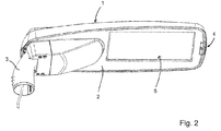
- Fig. 2
- eine perspektivische Unterseitenansicht der Leuchte nach
Fig. 1 , - Fig. 3
- eine Explosionsdarstellung der Leuchte nach
Fig. 1 mit den wesentlichen Funktionskomponenten, - Fig. 4
- eine Aufsicht auf die Leuchte nach
Fig. 1 ohne Leuchtengehäuseoberschale, - Fig. 5
- eine perspektivische Oberseitenansicht einer Steuereinheit der Leuchte nach
Fig. 1 ,
- Fig. 6
- eine perspektivische Unterseitenansicht der Steuereinheit nach
Fig. 5 , - Fig. 7
- eine perspektivische Oberseitenansicht einer Leuchtengehäuseunterschale mit ausgewählten montierten Funktionsgruppen,
- Fig. 8
- eine Frontaufsicht auf ein Anschlusssteckelement der Steuereinheit nach
Fig. 5 , - Fig. 9
- eine Aufsicht auf ein an der Leuchtengehäuseunterschale festgelegten Gegensteckelements der Leuchte,
- Fig. 10
- eine perspektivische Oberseitenansicht der erfindungsgemäßen Leuchte nach einer zweiten Ausführungsform,
- Fig. 11
- eine perspektivische Unterseitenansicht der Leuchte nach
Fig. 10 , - Fig. 12
- eine perspektivische Oberseitenansicht der Leuchte nach
Fig. 10 ohne Leuchtengehäuseoberschale, - Fig. 13
- eine perspektivische Oberseitenansicht der Steuereinheit der Leuchte nach
Fig. 10 und - Fig. 14
- eine Unterseitenansicht der Steuereinheit nach
Fig. 13 .
- Fig. 1
- 3 a perspective top view of a luminaire according to the invention according to a first embodiment,
- Fig. 2
- a perspective bottom view of the light after
Fig. 1 . - Fig. 3
- an exploded view of the light after
Fig. 1 with the essential functional components, - Fig. 4
- a view of the light after
Fig. 1 without luminaire housing upper shell, - Fig. 5
- a top perspective view of a control unit of the light according to
Fig. 1 .
- Fig. 6
- a bottom perspective view of the control unit according to
Fig. 5 . - Fig. 7
- a top perspective view of a luminaire housing lower shell with selected assembled functional groups,
- Fig. 8
- a frontal view of a connector element of the control unit according to
Fig. 5 . - Fig. 9
- a plan view of a fixed to the lamp housing lower shell mating connector of the lamp,
- Fig. 10
- a top perspective view of the lamp according to the invention according to a second embodiment,
- Fig. 11
- a perspective bottom view of the light after
Fig. 10 . - Fig. 12
- a top perspective view of the light after
Fig. 10 without luminaire housing upper shell, - Fig. 13
- a top perspective view of the control unit of the light according to
Fig. 10 and - Fig. 14
- a bottom view of the control unit according to
Fig. 13 ,
Eine erfindungsgemäße Leuchte nach den
In dem Leuchtengehäuse sind als wesentliche Funktionskomponenten eine flächig ausgebildete Lichtscheibe 5, eine Mehrzahl von Lichtmodulen 6, eine Anschlussplatine 7 zum Kontaktieren der Lichtmodule 6 sowie eine Steuereinheit 8 und ein Gegensteckelement 9 zum Kontaktieren der Steuereinheit 8 vorgesehen. Die Steuereinheit 8 ist hierbei in eine an der Leuchtengehäuseunterschale 2 gebildete Montagemulde 10 eingesetzt. Die Montagemulde 10 weist zum Stützen und Positionieren der Steuereinheit 8 ausgebildete Rippen 11 auf. Zusätzlich ist das Gegenstückelement 9 in der Montagemulde 10 vorgesehen. Von dem Gegensteckelement 9 ist eine externe Anschlussleitung 12 der Leuchte und eine interne Verbindungsleitung 13 zu der Anschlussplatine 7 geführt. Die Zuführung der externen Anschlussleitung 12 erfolgt über den Montageadapter 3.In the luminaire housing, a
Die Lichtscheibe 5 überdeckt eine an der Leuchtengehäuseunterschale 2 gebildete Lichtaustrittsöffnung 14 der Leuchte. Im Bereich einer Innenseite der Lichtscheibe 5 sind die Lichtmodule 6 an die Lichtscheibe 5 angelegt. Zum Dichten kann an dem Leuchtmodul eine nicht dargestellte Dichtlippe vorgesehen sein, welche gegen die Lichtscheibe 5 angelegt ist. Eine Erstreckungsebene der Lichtmodule 6 ist hierbei parallel zu einer Erstreckungsebene der Lichtscheibe 5 orientiert.The
Die Steuereinheit 8, welche detailliert in den
Eine Aufsicht auf das Anschlusselement 17 ist in
Jeweils sind die ersten Steckpins 20, die zweiten Steckpins 21 und die dritten Steckpins 22 von der ringförmigen Wandung 18 umschlossen und punktsymmetrisch in Bezug auf einen Mittelpunkt des Anschlusssteckelements 17 ausgebildet. Die ringförmige Wandung 18 ist dabei nach Art einer Silikonradialdichtung ausgebildet. Die zylindrische Außenwandfläche 19 dient der Führung des Anschlusssteckelements 17 beim Einsetzen der Steuereinheit 8 in die Montagemulde 10 der Leuchte.In each case, the first plug-in
Eine zweite Ausführungsform der erfindungsgemäßen Leuchte nach den
Die modifizierte Ausführungsform der zentralen Steuereinheit 8 ist in
Gleiche Bauteile und Bauteilfunktionen sind durch gleiche Bezugszeichen gekennzeichnet.Identical components and component functions are identified by the same reference numerals.
- 11
- LeuchtengehäuseoberschaleLuminaire housing upper shell
- 22
- LeuchtengehäuseunterschaleLuminaire housing bottom shell
- 33
- Montageadaptermounting adapter
- 44
- VerbindungsklipVerbindungsklip
- 55
- LichtscheibeLens
- 66
- Lichtmodullight module
- 77
- Anschlussplatineconnection board
- 88th
- Steuereinheitcontrol unit
- 99
- GegensteckelementMating plug element
- 1010
- Montagemuldemounting recess
- 1111
- Ripperib
- 1212
- Anschlussleitungconnecting cable
- 1313
- Verbindungsleitungconnecting line
- 1414
- LichtaustrittsöffnungLight opening
- 1515
- ModulgehäuseoberschaleModule Housing Faceplate
- 1616
- ModulgehäuseunterschaleModule housing shell
- 1717
- AnschlusssteckelementConnection plug-in element
- 1818
- ringförmige Wandungannular wall
- 1919
- zylindrische Außenwandflächecylindrical outer wall surface
- 2020
- SteckpinSteckpin
- 2121
- SteckpinSteckpin
- 2222
- SteckpinSteckpin
- 2323
- GegensteckpinGegensteckpin
- 2424
- GegensteckpinGegensteckpin
- 2525
- Öffnungopening
- 2626
- Anschlussadapterconnection adapter
- 2727
- Sensorsensor
Claims (14)
Priority Applications (1)
| Application Number | Priority Date | Filing Date | Title |
|---|---|---|---|
| EP16158909.8A EP3217073B1 (en) | 2016-03-07 | 2016-03-07 | Lamp and control unit for the lamp |
Applications Claiming Priority (1)
| Application Number | Priority Date | Filing Date | Title |
|---|---|---|---|
| EP16158909.8A EP3217073B1 (en) | 2016-03-07 | 2016-03-07 | Lamp and control unit for the lamp |
Publications (2)
| Publication Number | Publication Date |
|---|---|
| EP3217073A1 true EP3217073A1 (en) | 2017-09-13 |
| EP3217073B1 EP3217073B1 (en) | 2018-12-05 |
Family
ID=55524164
Family Applications (1)
| Application Number | Title | Priority Date | Filing Date |
|---|---|---|---|
| EP16158909.8A Active EP3217073B1 (en) | 2016-03-07 | 2016-03-07 | Lamp and control unit for the lamp |
Country Status (1)
| Country | Link |
|---|---|
| EP (1) | EP3217073B1 (en) |
Cited By (1)
| Publication number | Priority date | Publication date | Assignee | Title |
|---|---|---|---|---|
| WO2022022564A1 (en) * | 2020-07-31 | 2022-02-03 | 苏州卬锐电子科技有限公司 | Plugging device of lamp modularized electronic controller, and lamp device |
Citations (12)
| Publication number | Priority date | Publication date | Assignee | Title |
|---|---|---|---|---|
| US3247368A (en) | 1963-07-16 | 1966-04-19 | Arnold Company Inc | Fluorescent lighting fixture |
| US4796001A (en) * | 1986-01-16 | 1989-01-03 | North American Philips Corp. | Replacement ballast structures in roadway and/or area luminaires |
| US20040076001A1 (en) | 2002-10-17 | 2004-04-22 | Lutes Arthur L. | Leadless ballast |
| US20060055333A1 (en) * | 2004-09-16 | 2006-03-16 | Fiene Dale E | Ballast with integral connector |
| DE102005016533A1 (en) | 2005-04-08 | 2006-10-12 | Wago Verwaltungsgesellschaft Mbh | Wiring system for lighting units uses gas discharge lamps each connected in series to an electric/electronic fluorescent lamp ballast/choke |
| EP2177819A1 (en) * | 2008-10-17 | 2010-04-21 | Eclatec | Street lamp with modular components to facilitate maintenance |
| DE202012005355U1 (en) * | 2012-05-30 | 2012-08-28 | Fabio Tinagli | CONSTRUCTION OF LED RETROFIT ILLUMINATORS WITH INVERTER DRIVER ELECTRONICS |
| US20130040471A1 (en) * | 2011-08-08 | 2013-02-14 | Qualstar Corporation | Interposer for cobra head streetlight |
| US20140206239A1 (en) * | 2013-01-23 | 2014-07-24 | Thales Communications, Inc. | Backward compatible multichannel connector |
| EP2991455A1 (en) * | 2014-08-26 | 2016-03-02 | GRT Tech Co., Ltd. | Electronic device replacement structure |
| EP2990716A1 (en) * | 2014-08-26 | 2016-03-02 | GRT Tech Co., Ltd. | Light emitting diode lamp structure |
| US20160061425A1 (en) * | 2014-08-26 | 2016-03-03 | Hsuan-Chih Lin | Light emitting diode lamp structure |
-
2016
- 2016-03-07 EP EP16158909.8A patent/EP3217073B1/en active Active
Patent Citations (12)
| Publication number | Priority date | Publication date | Assignee | Title |
|---|---|---|---|---|
| US3247368A (en) | 1963-07-16 | 1966-04-19 | Arnold Company Inc | Fluorescent lighting fixture |
| US4796001A (en) * | 1986-01-16 | 1989-01-03 | North American Philips Corp. | Replacement ballast structures in roadway and/or area luminaires |
| US20040076001A1 (en) | 2002-10-17 | 2004-04-22 | Lutes Arthur L. | Leadless ballast |
| US20060055333A1 (en) * | 2004-09-16 | 2006-03-16 | Fiene Dale E | Ballast with integral connector |
| DE102005016533A1 (en) | 2005-04-08 | 2006-10-12 | Wago Verwaltungsgesellschaft Mbh | Wiring system for lighting units uses gas discharge lamps each connected in series to an electric/electronic fluorescent lamp ballast/choke |
| EP2177819A1 (en) * | 2008-10-17 | 2010-04-21 | Eclatec | Street lamp with modular components to facilitate maintenance |
| US20130040471A1 (en) * | 2011-08-08 | 2013-02-14 | Qualstar Corporation | Interposer for cobra head streetlight |
| DE202012005355U1 (en) * | 2012-05-30 | 2012-08-28 | Fabio Tinagli | CONSTRUCTION OF LED RETROFIT ILLUMINATORS WITH INVERTER DRIVER ELECTRONICS |
| US20140206239A1 (en) * | 2013-01-23 | 2014-07-24 | Thales Communications, Inc. | Backward compatible multichannel connector |
| EP2991455A1 (en) * | 2014-08-26 | 2016-03-02 | GRT Tech Co., Ltd. | Electronic device replacement structure |
| EP2990716A1 (en) * | 2014-08-26 | 2016-03-02 | GRT Tech Co., Ltd. | Light emitting diode lamp structure |
| US20160061425A1 (en) * | 2014-08-26 | 2016-03-03 | Hsuan-Chih Lin | Light emitting diode lamp structure |
Cited By (1)
| Publication number | Priority date | Publication date | Assignee | Title |
|---|---|---|---|---|
| WO2022022564A1 (en) * | 2020-07-31 | 2022-02-03 | 苏州卬锐电子科技有限公司 | Plugging device of lamp modularized electronic controller, and lamp device |
Also Published As
| Publication number | Publication date |
|---|---|
| EP3217073B1 (en) | 2018-12-05 |
Similar Documents
| Publication | Publication Date | Title |
|---|---|---|
| EP1405377B1 (en) | Led-module for illuminating devices | |
| DE102017131179B4 (en) | Lighting device, LED module for a lighting device, and method of assembling a lighting device | |
| EP1983620B1 (en) | Socket with orientation lighting | |
| EP1610422A1 (en) | Electrical connecting device | |
| EP3114403B1 (en) | Light fixture comprising interchangeable lighting modules | |
| EP2241797A2 (en) | Illumination device | |
| DE202015009802U1 (en) | Device for charging an electrically operated vehicle | |
| DE102009042615B4 (en) | Connection element for the electrical connection of an LED | |
| WO2012150124A1 (en) | Lighting device | |
| WO2014082616A1 (en) | Signal column | |
| DE202010016257U1 (en) | LED module with housing connector | |
| EP3217073B1 (en) | Lamp and control unit for the lamp | |
| DE102014222793A1 (en) | Operating light and method for operating a surgical light | |
| EP2429044B1 (en) | Electric installation device | |
| DE102007046818A1 (en) | Electrical shock-proof power socket for use in building installation, has light conductor coupling light and formed at central piece or cover frame, where conductor is protruded in area of base until below support ring | |
| EP2694874B1 (en) | Device for fastening and contacting a lighting means and/or a lighting module, and lamp | |
| DE102014215985A1 (en) | LED holder for holding a LED module | |
| DE102017001929A1 (en) | Electronic module for an electric motor, in particular a pump set | |
| WO2017125546A1 (en) | Lamp | |
| DE102009054620A1 (en) | Light module i.e. LED module, for use in light assembly utilized as e.g. external illumination in motor vehicle, has recess formed in front side of socket such that recess accommodates electric and electronic components of controller | |
| DE102010014948A1 (en) | Arrangement for energetic supply of light unit e.g. organic LED, for vehicle, has structure component comprising coil with lead lines, where self-contained housing and structure component are galvanically separated | |
| DE202015009051U1 (en) | signaling device | |
| WO2020152039A1 (en) | Lighting unit, illuminable component, and method for the production thereof | |
| DE102012214490A1 (en) | Light module and cover thereof | |
| DE102008020998A1 (en) | Intrinsically safe headlight |
Legal Events
| Date | Code | Title | Description |
|---|---|---|---|
| PUAI | Public reference made under article 153(3) epc to a published international application that has entered the european phase |
Free format text: ORIGINAL CODE: 0009012 |
|
| STAA | Information on the status of an ep patent application or granted ep patent |
Free format text: STATUS: THE APPLICATION HAS BEEN PUBLISHED |
|
| AK | Designated contracting states |
Kind code of ref document: A1 Designated state(s): AL AT BE BG CH CY CZ DE DK EE ES FI FR GB GR HR HU IE IS IT LI LT LU LV MC MK MT NL NO PL PT RO RS SE SI SK SM TR |
|
| AX | Request for extension of the european patent |
Extension state: BA ME |
|
| RAP1 | Party data changed (applicant data changed or rights of an application transferred) |
Owner name: HELLA GMBH & CO. KGAA |
|
| STAA | Information on the status of an ep patent application or granted ep patent |
Free format text: STATUS: REQUEST FOR EXAMINATION WAS MADE |
|
| 17P | Request for examination filed |
Effective date: 20180313 |
|
| RAP1 | Party data changed (applicant data changed or rights of an application transferred) |
Owner name: LUNUX GMBH |
|
| RBV | Designated contracting states (corrected) |
Designated state(s): AL AT BE BG CH CY CZ DE DK EE ES FI FR GB GR HR HU IE IS IT LI LT LU LV MC MK MT NL NO PL PT RO RS SE SI SK SM TR |
|
| RIC1 | Information provided on ipc code assigned before grant |
Ipc: F21W 131/103 20060101ALI20180425BHEP Ipc: F21Y 115/10 20160101ALI20180425BHEP Ipc: F21V 23/06 20060101ALI20180425BHEP Ipc: H01R 24/86 20110101ALI20180425BHEP Ipc: F21S 8/08 20060101AFI20180425BHEP Ipc: H01R 24/68 20110101ALI20180425BHEP Ipc: F21Y 101/00 20160101ALI20180425BHEP Ipc: F21V 23/00 20150101ALI20180425BHEP |
|
| INTG | Intention to grant announced |
Effective date: 20180611 |
|
| GRAP | Despatch of communication of intention to grant a patent |
Free format text: ORIGINAL CODE: EPIDOSNIGR1 |
|
| STAA | Information on the status of an ep patent application or granted ep patent |
Free format text: STATUS: GRANT OF PATENT IS INTENDED |
|
| GRAS | Grant fee paid |
Free format text: ORIGINAL CODE: EPIDOSNIGR3 |
|
| GRAA | (expected) grant |
Free format text: ORIGINAL CODE: 0009210 |
|
| STAA | Information on the status of an ep patent application or granted ep patent |
Free format text: STATUS: THE PATENT HAS BEEN GRANTED |
|
| AK | Designated contracting states |
Kind code of ref document: B1 Designated state(s): AL AT BE BG CH CY CZ DE DK EE ES FI FR GB GR HR HU IE IS IT LI LT LU LV MC MK MT NL NO PL PT RO RS SE SI SK SM TR |
|
| REG | Reference to a national code |
Ref country code: GB Ref legal event code: FG4D Free format text: NOT ENGLISH |
|
| REG | Reference to a national code |
Ref country code: CH Ref legal event code: EP |
|
| REG | Reference to a national code |
Ref country code: AT Ref legal event code: REF Ref document number: 1073511 Country of ref document: AT Kind code of ref document: T Effective date: 20181215 |
|
| REG | Reference to a national code |
Ref country code: IE Ref legal event code: FG4D Free format text: LANGUAGE OF EP DOCUMENT: GERMAN |
|
| REG | Reference to a national code |
Ref country code: DE Ref legal event code: R096 Ref document number: 502016002662 Country of ref document: DE |
|
| REG | Reference to a national code |
Ref country code: NL Ref legal event code: MP Effective date: 20181205 |
|
| REG | Reference to a national code |
Ref country code: LT Ref legal event code: MG4D |
|
| PG25 | Lapsed in a contracting state [announced via postgrant information from national office to epo] |
Ref country code: FI Free format text: LAPSE BECAUSE OF FAILURE TO SUBMIT A TRANSLATION OF THE DESCRIPTION OR TO PAY THE FEE WITHIN THE PRESCRIBED TIME-LIMIT Effective date: 20181205 Ref country code: BG Free format text: LAPSE BECAUSE OF FAILURE TO SUBMIT A TRANSLATION OF THE DESCRIPTION OR TO PAY THE FEE WITHIN THE PRESCRIBED TIME-LIMIT Effective date: 20190305 Ref country code: HR Free format text: LAPSE BECAUSE OF FAILURE TO SUBMIT A TRANSLATION OF THE DESCRIPTION OR TO PAY THE FEE WITHIN THE PRESCRIBED TIME-LIMIT Effective date: 20181205 Ref country code: LV Free format text: LAPSE BECAUSE OF FAILURE TO SUBMIT A TRANSLATION OF THE DESCRIPTION OR TO PAY THE FEE WITHIN THE PRESCRIBED TIME-LIMIT Effective date: 20181205 Ref country code: ES Free format text: LAPSE BECAUSE OF FAILURE TO SUBMIT A TRANSLATION OF THE DESCRIPTION OR TO PAY THE FEE WITHIN THE PRESCRIBED TIME-LIMIT Effective date: 20181205 Ref country code: LT Free format text: LAPSE BECAUSE OF FAILURE TO SUBMIT A TRANSLATION OF THE DESCRIPTION OR TO PAY THE FEE WITHIN THE PRESCRIBED TIME-LIMIT Effective date: 20181205 Ref country code: NO Free format text: LAPSE BECAUSE OF FAILURE TO SUBMIT A TRANSLATION OF THE DESCRIPTION OR TO PAY THE FEE WITHIN THE PRESCRIBED TIME-LIMIT Effective date: 20190305 |
|
| PG25 | Lapsed in a contracting state [announced via postgrant information from national office to epo] |
Ref country code: RS Free format text: LAPSE BECAUSE OF FAILURE TO SUBMIT A TRANSLATION OF THE DESCRIPTION OR TO PAY THE FEE WITHIN THE PRESCRIBED TIME-LIMIT Effective date: 20181205 Ref country code: GR Free format text: LAPSE BECAUSE OF FAILURE TO SUBMIT A TRANSLATION OF THE DESCRIPTION OR TO PAY THE FEE WITHIN THE PRESCRIBED TIME-LIMIT Effective date: 20190306 Ref country code: SE Free format text: LAPSE BECAUSE OF FAILURE TO SUBMIT A TRANSLATION OF THE DESCRIPTION OR TO PAY THE FEE WITHIN THE PRESCRIBED TIME-LIMIT Effective date: 20181205 Ref country code: AL Free format text: LAPSE BECAUSE OF FAILURE TO SUBMIT A TRANSLATION OF THE DESCRIPTION OR TO PAY THE FEE WITHIN THE PRESCRIBED TIME-LIMIT Effective date: 20181205 |
|
| PG25 | Lapsed in a contracting state [announced via postgrant information from national office to epo] |
Ref country code: NL Free format text: LAPSE BECAUSE OF FAILURE TO SUBMIT A TRANSLATION OF THE DESCRIPTION OR TO PAY THE FEE WITHIN THE PRESCRIBED TIME-LIMIT Effective date: 20181205 |
|
| PG25 | Lapsed in a contracting state [announced via postgrant information from national office to epo] |
Ref country code: IT Free format text: LAPSE BECAUSE OF FAILURE TO SUBMIT A TRANSLATION OF THE DESCRIPTION OR TO PAY THE FEE WITHIN THE PRESCRIBED TIME-LIMIT Effective date: 20181205 Ref country code: PT Free format text: LAPSE BECAUSE OF FAILURE TO SUBMIT A TRANSLATION OF THE DESCRIPTION OR TO PAY THE FEE WITHIN THE PRESCRIBED TIME-LIMIT Effective date: 20190405 Ref country code: CZ Free format text: LAPSE BECAUSE OF FAILURE TO SUBMIT A TRANSLATION OF THE DESCRIPTION OR TO PAY THE FEE WITHIN THE PRESCRIBED TIME-LIMIT Effective date: 20181205 Ref country code: PL Free format text: LAPSE BECAUSE OF FAILURE TO SUBMIT A TRANSLATION OF THE DESCRIPTION OR TO PAY THE FEE WITHIN THE PRESCRIBED TIME-LIMIT Effective date: 20181205 |
|
| PG25 | Lapsed in a contracting state [announced via postgrant information from national office to epo] |
Ref country code: SM Free format text: LAPSE BECAUSE OF FAILURE TO SUBMIT A TRANSLATION OF THE DESCRIPTION OR TO PAY THE FEE WITHIN THE PRESCRIBED TIME-LIMIT Effective date: 20181205 Ref country code: EE Free format text: LAPSE BECAUSE OF FAILURE TO SUBMIT A TRANSLATION OF THE DESCRIPTION OR TO PAY THE FEE WITHIN THE PRESCRIBED TIME-LIMIT Effective date: 20181205 Ref country code: RO Free format text: LAPSE BECAUSE OF FAILURE TO SUBMIT A TRANSLATION OF THE DESCRIPTION OR TO PAY THE FEE WITHIN THE PRESCRIBED TIME-LIMIT Effective date: 20181205 Ref country code: SK Free format text: LAPSE BECAUSE OF FAILURE TO SUBMIT A TRANSLATION OF THE DESCRIPTION OR TO PAY THE FEE WITHIN THE PRESCRIBED TIME-LIMIT Effective date: 20181205 Ref country code: IS Free format text: LAPSE BECAUSE OF FAILURE TO SUBMIT A TRANSLATION OF THE DESCRIPTION OR TO PAY THE FEE WITHIN THE PRESCRIBED TIME-LIMIT Effective date: 20190405 |
|
| REG | Reference to a national code |
Ref country code: DE Ref legal event code: R097 Ref document number: 502016002662 Country of ref document: DE |
|
| PLBE | No opposition filed within time limit |
Free format text: ORIGINAL CODE: 0009261 |
|
| STAA | Information on the status of an ep patent application or granted ep patent |
Free format text: STATUS: NO OPPOSITION FILED WITHIN TIME LIMIT |
|
| PG25 | Lapsed in a contracting state [announced via postgrant information from national office to epo] |
Ref country code: DK Free format text: LAPSE BECAUSE OF FAILURE TO SUBMIT A TRANSLATION OF THE DESCRIPTION OR TO PAY THE FEE WITHIN THE PRESCRIBED TIME-LIMIT Effective date: 20181205 Ref country code: MC Free format text: LAPSE BECAUSE OF FAILURE TO SUBMIT A TRANSLATION OF THE DESCRIPTION OR TO PAY THE FEE WITHIN THE PRESCRIBED TIME-LIMIT Effective date: 20181205 Ref country code: SI Free format text: LAPSE BECAUSE OF FAILURE TO SUBMIT A TRANSLATION OF THE DESCRIPTION OR TO PAY THE FEE WITHIN THE PRESCRIBED TIME-LIMIT Effective date: 20181205 |
|
| REG | Reference to a national code |
Ref country code: CH Ref legal event code: PL |
|
| 26N | No opposition filed |
Effective date: 20190906 |
|
| PG25 | Lapsed in a contracting state [announced via postgrant information from national office to epo] |
Ref country code: LU Free format text: LAPSE BECAUSE OF NON-PAYMENT OF DUE FEES Effective date: 20190307 |
|
| REG | Reference to a national code |
Ref country code: BE Ref legal event code: MM Effective date: 20190331 |
|
| PG25 | Lapsed in a contracting state [announced via postgrant information from national office to epo] |
Ref country code: IE Free format text: LAPSE BECAUSE OF NON-PAYMENT OF DUE FEES Effective date: 20190307 Ref country code: CH Free format text: LAPSE BECAUSE OF NON-PAYMENT OF DUE FEES Effective date: 20190331 Ref country code: LI Free format text: LAPSE BECAUSE OF NON-PAYMENT OF DUE FEES Effective date: 20190331 |
|
| PG25 | Lapsed in a contracting state [announced via postgrant information from national office to epo] |
Ref country code: FR Free format text: LAPSE BECAUSE OF NON-PAYMENT OF DUE FEES Effective date: 20190331 Ref country code: BE Free format text: LAPSE BECAUSE OF NON-PAYMENT OF DUE FEES Effective date: 20190331 |
|
| PG25 | Lapsed in a contracting state [announced via postgrant information from national office to epo] |
Ref country code: TR Free format text: LAPSE BECAUSE OF FAILURE TO SUBMIT A TRANSLATION OF THE DESCRIPTION OR TO PAY THE FEE WITHIN THE PRESCRIBED TIME-LIMIT Effective date: 20181205 |
|
| PG25 | Lapsed in a contracting state [announced via postgrant information from national office to epo] |
Ref country code: MT Free format text: LAPSE BECAUSE OF FAILURE TO SUBMIT A TRANSLATION OF THE DESCRIPTION OR TO PAY THE FEE WITHIN THE PRESCRIBED TIME-LIMIT Effective date: 20181205 |
|
| REG | Reference to a national code |
Ref country code: DE Ref legal event code: R082 Ref document number: 502016002662 Country of ref document: DE Representative=s name: REICHERT & LINDNER PARTNERSCHAFT PATENTANWAELT, DE |
|
| REG | Reference to a national code |
Ref country code: DE Ref legal event code: R082 Ref document number: 502016002662 Country of ref document: DE Representative=s name: REICHERT & LINDNER PARTNERSCHAFT PATENTANWAELT, DE |
|
| REG | Reference to a national code |
Ref country code: DE Ref legal event code: R082 Ref document number: 502016002662 Country of ref document: DE Representative=s name: REICHERT & LINDNER PARTNERSCHAFT PATENTANWAELT, DE Ref country code: DE Ref legal event code: R081 Ref document number: 502016002662 Country of ref document: DE Owner name: LUNUX LIGHTING GMBH, DE Free format text: FORMER OWNER: LUNUX GMBH, 30880 LAATZEN, DE |
|
| GBPC | Gb: european patent ceased through non-payment of renewal fee |
Effective date: 20200307 |
|
| PG25 | Lapsed in a contracting state [announced via postgrant information from national office to epo] |
Ref country code: GB Free format text: LAPSE BECAUSE OF NON-PAYMENT OF DUE FEES Effective date: 20200307 |
|
| PG25 | Lapsed in a contracting state [announced via postgrant information from national office to epo] |
Ref country code: CY Free format text: LAPSE BECAUSE OF FAILURE TO SUBMIT A TRANSLATION OF THE DESCRIPTION OR TO PAY THE FEE WITHIN THE PRESCRIBED TIME-LIMIT Effective date: 20181205 |
|
| PG25 | Lapsed in a contracting state [announced via postgrant information from national office to epo] |
Ref country code: HU Free format text: LAPSE BECAUSE OF FAILURE TO SUBMIT A TRANSLATION OF THE DESCRIPTION OR TO PAY THE FEE WITHIN THE PRESCRIBED TIME-LIMIT; INVALID AB INITIO Effective date: 20160307 |
|
| REG | Reference to a national code |
Ref country code: DE Ref legal event code: R081 Ref document number: 502016002662 Country of ref document: DE Owner name: LUNUX LIGHTING GMBH, DE Free format text: FORMER OWNER: LUNUX LIGHTING GMBH, 30173 HANNOVER, DE |
|
| REG | Reference to a national code |
Ref country code: AT Ref legal event code: MM01 Ref document number: 1073511 Country of ref document: AT Kind code of ref document: T Effective date: 20210307 |
|
| PG25 | Lapsed in a contracting state [announced via postgrant information from national office to epo] |
Ref country code: MK Free format text: LAPSE BECAUSE OF FAILURE TO SUBMIT A TRANSLATION OF THE DESCRIPTION OR TO PAY THE FEE WITHIN THE PRESCRIBED TIME-LIMIT Effective date: 20181205 |
|
| PG25 | Lapsed in a contracting state [announced via postgrant information from national office to epo] |
Ref country code: AT Free format text: LAPSE BECAUSE OF NON-PAYMENT OF DUE FEES Effective date: 20210307 |
|
| PGFP | Annual fee paid to national office [announced via postgrant information from national office to epo] |
Ref country code: DE Payment date: 20230524 Year of fee payment: 8 |