EP3215349B1 - Machine and method for powder-based additive manufacturing - Google Patents
Machine and method for powder-based additive manufacturing Download PDFInfo
- Publication number
- EP3215349B1 EP3215349B1 EP15788040.2A EP15788040A EP3215349B1 EP 3215349 B1 EP3215349 B1 EP 3215349B1 EP 15788040 A EP15788040 A EP 15788040A EP 3215349 B1 EP3215349 B1 EP 3215349B1
- Authority
- EP
- European Patent Office
- Prior art keywords
- machine according
- working zone
- powder
- emission
- modules
- Prior art date
- Legal status (The legal status is an assumption and is not a legal conclusion. Google has not performed a legal analysis and makes no representation as to the accuracy of the status listed.)
- Active
Links
- 239000000843 powder Substances 0.000 title claims description 51
- 238000004519 manufacturing process Methods 0.000 title claims description 43
- 239000000654 additive Substances 0.000 title claims description 9
- 230000000996 additive effect Effects 0.000 title claims description 9
- 238000000034 method Methods 0.000 title claims description 9
- 230000003287 optical effect Effects 0.000 claims description 25
- 238000002844 melting Methods 0.000 claims description 20
- 230000008018 melting Effects 0.000 claims description 20
- 238000013519 translation Methods 0.000 claims description 15
- 238000005245 sintering Methods 0.000 claims description 8
- 230000000694 effects Effects 0.000 claims description 5
- 238000000151 deposition Methods 0.000 claims description 2
- 230000014616 translation Effects 0.000 description 12
- 230000004927 fusion Effects 0.000 description 9
- 238000006073 displacement reaction Methods 0.000 description 7
- 238000000149 argon plasma sintering Methods 0.000 description 3
- 239000000919 ceramic Substances 0.000 description 2
- 229910052500 inorganic mineral Inorganic materials 0.000 description 2
- 230000009021 linear effect Effects 0.000 description 2
- 239000011707 mineral Substances 0.000 description 2
- 238000007789 sealing Methods 0.000 description 2
- 230000000903 blocking effect Effects 0.000 description 1
- 238000010276 construction Methods 0.000 description 1
- 238000009826 distribution Methods 0.000 description 1
- 230000005670 electromagnetic radiation Effects 0.000 description 1
- 238000010894 electron beam technology Methods 0.000 description 1
- 230000005484 gravity Effects 0.000 description 1
- 239000000203 mixture Substances 0.000 description 1
- 239000002245 particle Substances 0.000 description 1
- 238000002360 preparation method Methods 0.000 description 1
- 238000011084 recovery Methods 0.000 description 1
Images


Classifications
-
- B—PERFORMING OPERATIONS; TRANSPORTING
- B23—MACHINE TOOLS; METAL-WORKING NOT OTHERWISE PROVIDED FOR
- B23K—SOLDERING OR UNSOLDERING; WELDING; CLADDING OR PLATING BY SOLDERING OR WELDING; CUTTING BY APPLYING HEAT LOCALLY, e.g. FLAME CUTTING; WORKING BY LASER BEAM
- B23K26/00—Working by laser beam, e.g. welding, cutting or boring
- B23K26/02—Positioning or observing the workpiece, e.g. with respect to the point of impact; Aligning, aiming or focusing the laser beam
- B23K26/06—Shaping the laser beam, e.g. by masks or multi-focusing
- B23K26/0604—Shaping the laser beam, e.g. by masks or multi-focusing by a combination of beams
-
- B—PERFORMING OPERATIONS; TRANSPORTING
- B22—CASTING; POWDER METALLURGY
- B22F—WORKING METALLIC POWDER; MANUFACTURE OF ARTICLES FROM METALLIC POWDER; MAKING METALLIC POWDER; APPARATUS OR DEVICES SPECIALLY ADAPTED FOR METALLIC POWDER
- B22F10/00—Additive manufacturing of workpieces or articles from metallic powder
- B22F10/20—Direct sintering or melting
- B22F10/28—Powder bed fusion, e.g. selective laser melting [SLM] or electron beam melting [EBM]
-
- B—PERFORMING OPERATIONS; TRANSPORTING
- B22—CASTING; POWDER METALLURGY
- B22F—WORKING METALLIC POWDER; MANUFACTURE OF ARTICLES FROM METALLIC POWDER; MAKING METALLIC POWDER; APPARATUS OR DEVICES SPECIALLY ADAPTED FOR METALLIC POWDER
- B22F12/00—Apparatus or devices specially adapted for additive manufacturing; Auxiliary means for additive manufacturing; Combinations of additive manufacturing apparatus or devices with other processing apparatus or devices
- B22F12/40—Radiation means
- B22F12/44—Radiation means characterised by the configuration of the radiation means
- B22F12/45—Two or more
-
- B—PERFORMING OPERATIONS; TRANSPORTING
- B22—CASTING; POWDER METALLURGY
- B22F—WORKING METALLIC POWDER; MANUFACTURE OF ARTICLES FROM METALLIC POWDER; MAKING METALLIC POWDER; APPARATUS OR DEVICES SPECIALLY ADAPTED FOR METALLIC POWDER
- B22F12/00—Apparatus or devices specially adapted for additive manufacturing; Auxiliary means for additive manufacturing; Combinations of additive manufacturing apparatus or devices with other processing apparatus or devices
- B22F12/40—Radiation means
- B22F12/46—Radiation means with translatory movement
- B22F12/48—Radiation means with translatory movement in height, e.g. perpendicular to the deposition plane
-
- B—PERFORMING OPERATIONS; TRANSPORTING
- B23—MACHINE TOOLS; METAL-WORKING NOT OTHERWISE PROVIDED FOR
- B23K—SOLDERING OR UNSOLDERING; WELDING; CLADDING OR PLATING BY SOLDERING OR WELDING; CUTTING BY APPLYING HEAT LOCALLY, e.g. FLAME CUTTING; WORKING BY LASER BEAM
- B23K26/00—Working by laser beam, e.g. welding, cutting or boring
- B23K26/34—Laser welding for purposes other than joining
- B23K26/342—Build-up welding
-
- B—PERFORMING OPERATIONS; TRANSPORTING
- B28—WORKING CEMENT, CLAY, OR STONE
- B28B—SHAPING CLAY OR OTHER CERAMIC COMPOSITIONS; SHAPING SLAG; SHAPING MIXTURES CONTAINING CEMENTITIOUS MATERIAL, e.g. PLASTER
- B28B1/00—Producing shaped prefabricated articles from the material
- B28B1/001—Rapid manufacturing of 3D objects by additive depositing, agglomerating or laminating of material
-
- B—PERFORMING OPERATIONS; TRANSPORTING
- B29—WORKING OF PLASTICS; WORKING OF SUBSTANCES IN A PLASTIC STATE IN GENERAL
- B29C—SHAPING OR JOINING OF PLASTICS; SHAPING OF MATERIAL IN A PLASTIC STATE, NOT OTHERWISE PROVIDED FOR; AFTER-TREATMENT OF THE SHAPED PRODUCTS, e.g. REPAIRING
- B29C64/00—Additive manufacturing, i.e. manufacturing of three-dimensional [3D] objects by additive deposition, additive agglomeration or additive layering, e.g. by 3D printing, stereolithography or selective laser sintering
- B29C64/10—Processes of additive manufacturing
- B29C64/141—Processes of additive manufacturing using only solid materials
- B29C64/153—Processes of additive manufacturing using only solid materials using layers of powder being selectively joined, e.g. by selective laser sintering or melting
-
- B—PERFORMING OPERATIONS; TRANSPORTING
- B29—WORKING OF PLASTICS; WORKING OF SUBSTANCES IN A PLASTIC STATE IN GENERAL
- B29C—SHAPING OR JOINING OF PLASTICS; SHAPING OF MATERIAL IN A PLASTIC STATE, NOT OTHERWISE PROVIDED FOR; AFTER-TREATMENT OF THE SHAPED PRODUCTS, e.g. REPAIRING
- B29C64/00—Additive manufacturing, i.e. manufacturing of three-dimensional [3D] objects by additive deposition, additive agglomeration or additive layering, e.g. by 3D printing, stereolithography or selective laser sintering
- B29C64/20—Apparatus for additive manufacturing; Details thereof or accessories therefor
- B29C64/25—Housings, e.g. machine housings
-
- B—PERFORMING OPERATIONS; TRANSPORTING
- B29—WORKING OF PLASTICS; WORKING OF SUBSTANCES IN A PLASTIC STATE IN GENERAL
- B29C—SHAPING OR JOINING OF PLASTICS; SHAPING OF MATERIAL IN A PLASTIC STATE, NOT OTHERWISE PROVIDED FOR; AFTER-TREATMENT OF THE SHAPED PRODUCTS, e.g. REPAIRING
- B29C64/00—Additive manufacturing, i.e. manufacturing of three-dimensional [3D] objects by additive deposition, additive agglomeration or additive layering, e.g. by 3D printing, stereolithography or selective laser sintering
- B29C64/20—Apparatus for additive manufacturing; Details thereof or accessories therefor
- B29C64/264—Arrangements for irradiation
- B29C64/268—Arrangements for irradiation using laser beams; using electron beams [EB]
-
- B—PERFORMING OPERATIONS; TRANSPORTING
- B33—ADDITIVE MANUFACTURING TECHNOLOGY
- B33Y—ADDITIVE MANUFACTURING, i.e. MANUFACTURING OF THREE-DIMENSIONAL [3-D] OBJECTS BY ADDITIVE DEPOSITION, ADDITIVE AGGLOMERATION OR ADDITIVE LAYERING, e.g. BY 3-D PRINTING, STEREOLITHOGRAPHY OR SELECTIVE LASER SINTERING
- B33Y10/00—Processes of additive manufacturing
-
- B—PERFORMING OPERATIONS; TRANSPORTING
- B33—ADDITIVE MANUFACTURING TECHNOLOGY
- B33Y—ADDITIVE MANUFACTURING, i.e. MANUFACTURING OF THREE-DIMENSIONAL [3-D] OBJECTS BY ADDITIVE DEPOSITION, ADDITIVE AGGLOMERATION OR ADDITIVE LAYERING, e.g. BY 3-D PRINTING, STEREOLITHOGRAPHY OR SELECTIVE LASER SINTERING
- B33Y30/00—Apparatus for additive manufacturing; Details thereof or accessories therefor
-
- B—PERFORMING OPERATIONS; TRANSPORTING
- B22—CASTING; POWDER METALLURGY
- B22F—WORKING METALLIC POWDER; MANUFACTURE OF ARTICLES FROM METALLIC POWDER; MAKING METALLIC POWDER; APPARATUS OR DEVICES SPECIALLY ADAPTED FOR METALLIC POWDER
- B22F10/00—Additive manufacturing of workpieces or articles from metallic powder
- B22F10/30—Process control
- B22F10/36—Process control of energy beam parameters
-
- B—PERFORMING OPERATIONS; TRANSPORTING
- B22—CASTING; POWDER METALLURGY
- B22F—WORKING METALLIC POWDER; MANUFACTURE OF ARTICLES FROM METALLIC POWDER; MAKING METALLIC POWDER; APPARATUS OR DEVICES SPECIALLY ADAPTED FOR METALLIC POWDER
- B22F12/00—Apparatus or devices specially adapted for additive manufacturing; Auxiliary means for additive manufacturing; Combinations of additive manufacturing apparatus or devices with other processing apparatus or devices
- B22F12/38—Housings, e.g. machine housings
-
- Y—GENERAL TAGGING OF NEW TECHNOLOGICAL DEVELOPMENTS; GENERAL TAGGING OF CROSS-SECTIONAL TECHNOLOGIES SPANNING OVER SEVERAL SECTIONS OF THE IPC; TECHNICAL SUBJECTS COVERED BY FORMER USPC CROSS-REFERENCE ART COLLECTIONS [XRACs] AND DIGESTS
- Y02—TECHNOLOGIES OR APPLICATIONS FOR MITIGATION OR ADAPTATION AGAINST CLIMATE CHANGE
- Y02P—CLIMATE CHANGE MITIGATION TECHNOLOGIES IN THE PRODUCTION OR PROCESSING OF GOODS
- Y02P10/00—Technologies related to metal processing
- Y02P10/25—Process efficiency
Definitions
- the present invention relates to a machine and a method of additive manufacturing based on powder by sintering or by melting of grains of said powder using an energy beam.
- energy beam is meant an electromagnetic radiation (for example a laser beam) or a beam of particles (for example an electron beam).
- the advantage of manufacturing by selective fusion of superimposed powder layers lies mainly in the fact that the shape of the parts can be modeled by computer and that the parts can then be manufactured on the basis of this modeling by control of the energy beam by the computer.
- this technique is well suited to the manufacture of parts of small dimensions and complex shapes which are difficult to manufacture with other methods.
- the laser sintering technique consists in manufacturing the part layer after layer, by stacking the consolidated powder layers and fused one on top of the other by the laser beam in a stacking direction.
- the term "powder” means a powder or a mixture of powders.
- the powder may for example be metallic or mineral, for example ceramic.
- a layering device is used.
- a device can comprise a cylinder or roller capable of distributing the powder in a layer on a production tray.
- a cylinder or roller capable of distributing the powder in a layer on a production tray.
- the first layer is deposited and then welded directly to the production plate.
- the other layers are then formed successively so as to obtain a stacking from the first layer.
- a source is provided which emits an energy beam whose orientation is controlled by galvanometric mirrors, and an optical lens making it possible to focus the energy beam on the layers of powder deposited on the manufacturing tray.
- the document WO-A1-2013 / 178825 recommends providing a machine comprising two separate manufacturing trays each associated with a source of emission of an energy beam and with means of controlling the energy beam specific to each source so as to form a part on each of the plates.
- the machine also includes a layering device common to the two manufacturing platforms.
- the document US 2013/270750 A1 discloses a machine and method for additive manufacturing of parts by laser sintering comprising two emission modules, said emission modules having a focusing lens having a variable focal length.
- the present invention aims to remedy this drawback.
- the present invention aims to provide a sintering machine making it possible to reduce the cycle time necessary for the manufacture of each part and to achieve a particularly precise melting of the powder layers.
- the machine for the additive manufacturing of parts by sintering or powder melting comprises a chassis, at least one working area, and at least two energy beam emission and control modules mounted at the inside the chassis and each provided with an emission source and with an optical focusing means of the energy beam emitted by said source.
- the emission and control modules each act on said work area for the manufacture of the same part.
- At least the optical focusing means of each module is axially movable in translation relative to the chassis along a vertical axis.
- the machine further comprises at least two associated actuators each with only one of the optical focusing means for adjusting the vertical axial position of said means with respect to the working area independently of one another.
- the adjustment of the axial positioning of the optical focusing means independently of one another makes it possible to be able to place each of these means at the desired working distance relative to the working area.
- the focusing means which can for example be lenses, each have an actual focal length after manufacture which differs from their theoretical focal distance. It is thus possible to carry out an independent adjustment of the working distance or height of each focusing means as a function of its actual focal distance by axial displacement of these means which are movable independently of one another. It is thus possible to obtain a particularly precise melting of the powder layers successively deposited on the working area by this independent adjustment of the axial position of the focusing means.
- the machine comprises a single production plate associated with said work area.
- the emission and control modules may each comprise a casing supporting the emission source and the associated optical focusing means.
- the casing of each module is axially movable in translation relative to the chassis under the effect of the associated actuator. In this case, the adjustment of the working distance of each focusing means is obtained by moving the housing supporting said means.
- each actuator comprises a linear displacement control member
- the chassis comprising means for guiding each of said control members.
- the machine further comprises means for adjusting the the angular orientation of the guide axes of the guide means with respect to said work area.
- the chassis may include at least one frame delimiting the working area and at least one box supporting the emission and control modules, the actuators and the guide means, the adjustment means being interposed between the frame and the box.
- the machine further comprises means for adjusting the angular orientation of the optical axis of each focusing means with respect to said working area.
- the orientation of each focusing means so that its optical axis is perfectly perpendicular to the working area.
- Such an adjustment prior to the melting operations further favors obtaining good melting precision.
- the machine comprises at least two bases each supporting one of the emission and control modules and each connected to the actuator associated with said module, said adjustment means being interposed between each support base and the associated module .
- the adjustment means may each comprise a body, a slide mounted movable inside the body, a member for adjusting the position of the slide inside the body, and an actuation socket mounted on the body and cooperating with the slider so as to obtain, under the effect of a displacement of the slider, a translation of said sleeve in a direction transverse to the direction of movement of said slider.
- the machine comprises at least two separate work zones, and at least two modules for transmitting and controlling an energy beam specific to each of the work zones.
- the machine comprises a layering device common to the two working zones.
- each actuator comprises an electric motor associated with a screw-nut system or a jack.
- each focusing means is adjusted relative to the working area independently of one another before the fusion operations.
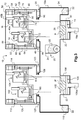
- FIG. 1 there is shown an embodiment of a machine, referenced 10 as a whole, intended for the additive manufacturing of at least one part P and shown in a position assumed to be vertical.
- at least one piece P is meant a single piece P or a set of several pieces P produced simultaneously.
- the machine 10 comprises a chassis 12, two modules 14, 16 for transmitting and controlling a separate energy beam, a work plate 18 common to the two modules and a layering device 20 for applying powder 22 to the work tray.
- the two distinct energy beams emitted are shown in dotted lines.
- the working distance between each module 14, 16 and the associated plate 18 is adjusted independently of one another.
- the layering device 20 comprises a hopper 24 for storing and supplying the powder 22 placed above the working plate 18, and a rotary roller 26 for dosing the powder on a flat working area 28 delimited by the frame 12.
- the roller 26 extends through a lower opening of the hopper 24 and makes it possible to control the quantity of powder transferred by gravity.
- the roller 26 may for example comprise a plurality of grooves formed on its outer surface and having the function of transferring a reproducible dose of powder onto the working area 28.
- the layering device 20 may also comprise, in combination or as a replacement roller, another means of distribution, for example a squeegee.
- a squeegee for more details on the design of such a layering device, one can for example refer to patent applications WO-A1-2013 / 092757 and WO-A1-2013 / 178825 .
- the working area 28 is delimited by a jacket 30 of the chassis inside of which the working plate 18 is slidably mounted along a vertical axis 18a.
- the jacket 30 has a cross section of the same shape as that of the plate 18, for example circular, square, rectangular, etc.
- the jacket 30 is located opposite the area of action of the modules 14, 16 which both act on the working area 28.
- the jacket 30 is integral with the chassis 12 by being attached and fixed to said chassis or by being made in one piece with the latter.
- the layering device 20 is movable in translation inside the chassis 12 in a horizontal direction of movement illustrated diagrammatically by the arrow referenced 32 so as to be able to deliver the predetermined quantity of powder each time it passes over the working area 28
- the surplus powder is pushed into a container 34 for recovering the chassis 12 of the machine.
- the container 34 is adjacent to the jacket 30.
- the separate modules 14, 16 are arranged side by side inside the chassis 12 and designed to act on the working area 28 which is common to these two modules.
- the modules 14, 16 being identical in the illustrated embodiment example, we will describe here only the components of the module 14 using the reference “a” it being understood that the identical components of the other module 16 bear the reference “b” on the figure 1 .
- the module 14 comprises a source 40a for emitting an energy beam, for example of the laser type, two galvanometric mirrors 42a capable of controlling the orientation of the emitted beam, and a lens 44a for focusing said beam on the work area 28 in order to be able to heat each layer of powder deposited in a pattern corresponding to the section of the part P to be manufactured and thus selectively carry out the melting of the powder.
- a source 40a for emitting an energy beam for example of the laser type
- two galvanometric mirrors 42a capable of controlling the orientation of the emitted beam
- a lens 44a for focusing said beam on the work area 28 in order to be able to heat each layer of powder deposited in a pattern corresponding to the section of the part P to be manufactured and thus selectively carry out the melting of the powder.
- the module 14 also includes a casing 46a on which the source 40a, the mirrors 42a and the lens 44a are mounted.
- the casing 46a is supported by a base 48 of the chassis.
- the support base 48 is located vertically above the work area 28.
- the casing 46b of the module 16 is also supported by a base 50 of the chassis which is adjacent to the base 48.
- the bases 48 , 50 for supporting the modules each include an opening (not shown) to allow the passage of the energy beams emitted by the sources 40a, 40b and focused by the lenses 44a, 44b.
- the machine 10 also comprises two distinct actuators 52, 54 each associated with one of the modules 14, 16 so as to be able to modify the axial position of the modules independently of one another.
- Each module 14, 16 is axially movable in translation relative to the chassis 12 along a vertical axis.
- the actuators 52, 54 are fixed to the chassis 12 and mounted inside the latter.
- the actuators 52, 54 are respectively connected to the support bases 48, 50 to allow the displacement of the modules 14, 16.
- each actuator 52, 54 comprises an electric motor 56, 58 fixed to the chassis 12 and a screw-nut system whose screw 60, 62 is rotated by the motor and whose nut 64, 66 is guided in translation by a slide 68, 70 of the chassis, with a vertical guide axis.
- the guide axes of the slides 68, 70 are substantially parallel to each other.
- the nut 64, 66 is fixed to the support base 48, 50 to allow the axial displacement of the associated module 14, 16.
- the nut 64, 66 forms a control member with vertical linear action of the associated module 14, 16.
- the screw-nut system can be of the ball, roller or direct-drive type between the screw and the nut.
- the use of a screw-nut system makes it possible to be able to control extremely precisely the axial position of each module 14, 16 relative to the chassis 12.
- the machine 10 further comprises a pair of adjustment means 72 associated with each module 14, 16 in order to be able to adjust the angular orientation of the optical axis of the lens 44a, 44b of the module considered with respect to the working area 28.
- Each pair of adjustment means 72 is interposed between the support base 48, 50 and the associated casing 46a, 46b of the module.
- the adjustment of the angular orientation of the optical axis of each lens 44a, 44b is obtained by angular orientation of the associated module 14, 16.
- the adjustment means 72 of the same pair are arranged on either side of the lens 44a, 44b of the associated module.
- a ball joint is also provided between the support base 48, 50 and the associated casing 46a, 46b.
- the adjustment means 72 are identical to each other.
- the adjustment means 72 comprises a base plate 74 which is fixed on the support base of the associated module, and a body 76 fixed on the plate and delimiting between them a housing 78 inside of which a slide 80 is mounted
- the slide 80 comprises a flat lower face 80a which comes to bear against the plate 74 and an upper face 80b frustoconical forming a slope.
- the adjustment means 72 also comprises an adjustment screw 82 movable in rotation inside the housing 78 of the body to allow the displacement in translation of the slide 80 along a horizontal axis 80c, and a blocking tie rod 84 mounted on said body. to ensure the immobilization in rotation of the screw 82.
- the screw 82 comprises a cylindrical portion 82a partially mounted inside the body 76 and a plurality of recesses 82b formed on the outer surface of the cylindrical portion and designed to receive a lower end of the tie rod 84 so as to obtain the rotation locking of the screw.
- the screw 82 also includes a threaded rod 82c extending the cylindrical portion 82a and mounted inside a corresponding threaded bore 80d of the slide.
- the tie rod 84 is movable relative to the body 76 between a locking position illustrated in the figure 2 in which its lower end is housed inside one of the recesses 82b, and an unlocking position in which said end is set back from the cylindrical portion 82a so as to be able to manually rotate the screw 82.
- a return spring (not shown) keeps the tie rod 84 in the locked position and automatically returns it to this position after rotation of the screw 82 by an operator.
- the adjustment means 72 further comprises an actuating sleeve 86 mounted on the body 76 and comprising a lower face 86a bearing against the upper face 80b of the slide and in shape agreement with said upper face.
- the sleeve 86 comprises an upper face 86b intended to come to bear against the lower face of the casing of the associated module.
- the sleeve 86 is movable in translation relative to the body 76 along an axis 86c perpendicular to the axis 80c of the slide under the effect of a displacement of said slide which is controlled by a rotation of the screw 82.
- the chassis 12 comprises a lower fixed frame 12a and an upper box 12b mounted on the frame.
- the frame 12a delimits the working area 28 and includes the recovery tank 34.
- the layering device 20 is mounted inside the frame 12a.
- the box 12b supports the modules 14, 16, the support bases 48, 50 as well as the actuators 52, 54 and the associated slides 68, 70. These means are mounted inside the box 12b.
- An annular sealing member 90 such as a seal, is mounted axially between the frame 12a and the box 12b.
- the frame 12a and the box 12b each include an opening 92, 94 for the passage of the energy beams emitted by the sources 40a, 40b and focused by the lenses 44a, 44b.
- the openings 92, 94 are aligned vertically.
- the machine 10 also comprises two adjustment means 96 provided to allow the angular orientation of the guide axes of the slides 68, 70 relative to the working area 28.
- the adjustment means 96 are interposed between the frame 12a and the box 12b in order to be able to obtain the adjustment of these axes by angular orientation of the box 12b supporting the slides 68, 70.
- the adjustment means 96 are arranged between an upper face of the frame 12a and a lower face of the box 12b and arranged on either side other of the openings 92, 94.
- a ball joint is also provided between the upper face of the frame 12a and the lower face of the box 12b.
- Each adjustment means 96 has a structure identical to that of the adjustment means 72 previously described. The upper face of the actuating sleeve of each adjustment means 96 bears against the lower face of the box 12b.
- a first step the angular orientation of the box 12b is manually adjusted relative to the fixed frame 12a.
- the adjustment screws of the adjustment means 96 are actuated in order to vertically move the actuating sockets and rotate the box 12b about a vertical axis relative to the frame 12a. This adjustment is made so as to orient the guide axes of the slides 68, 70 perpendicular to the working area 28.
- a second manual adjustment step the angular orientation of the optical axis of each lens 44a, 44b is adjusted relative to the working area 28.
- the adjustment means are actuated.
- adjustment 72 for vertically moving the actuating sockets and pivoting each module 14, 16 about a vertical axis relative to the support base 48 and to the frame 12a.
- This step makes it possible to manually adjust the orientation of the optical axis of each lens 44a, 44b so that it is parallel to the axis of the associated slide 68, 70.
- the optical axis of each lens 44a, 44b extends parallel to the axis 18a of translation of the work plate and perpendicular to the work area 28.
- the layering device 20 is first controlled to deposit a first layer of powder on the working area 28 of the production plate. After depositing, the first layer of powder extends substantially horizontally.
- the powder may for example be metallic or mineral, for example ceramic.
- the powder is metallic.
- the actuators 52, 54 are controlled to independently adjust the axial position of each lens 44a, 44b of the modules relative to the working area 28.
- the vertical translations modules 14, 16 inside the chassis 12 are controlled by the actuators 52, 54 independently of one another.
- each lens 44a, 44b it is possible to adjust the axial distance separating each lens 44a, 44b from the working area 28 according to the actual focal distance which is specific to the optical chain of the associated module 14, 16 constituted by the emission source 40a, 40b , the mirrors 42a, 42 and said lens.
- the actual focal length of each lens is generally different from the theoretical focal distance due to manufacturing inaccuracies. It is thus possible to carry out an independent adjustment of the working distance of each lens as a function of the actual focal distance so that the rays of the energy beam emitted by each source 40a, 40b converge on the working area 28.
- each lens 44a, 44b, and more generally of each module 14, 16 is thus thus adjusted independently of one another as a function of the actual focal distance of said lens, and more generally as a function of the focal distance of the associated optical chain. This favors the obtaining of a good melting precision of the powder layer deposited on the working area 28 by each module 14, 16.
- This adjustment of the focusing of the optical chain of each module 14, 16 carried out during parts manufacturing is all the more effective that the steps of adjusting the orientation of the optical axis of each lens 44a, 44b performed before this manufacturing are precise.
- each source 40a, 40b is controlled to emit an energy beam whose orientation is controlled by the associated mirrors 42a, 42b and which passes through the associated lens 44a, 44b.
- Each lens 44a, 44b makes it possible to focus the associated energy beam according to the adjustment carried out beforehand which is specific to it in order to heat the powder layer according to a pattern corresponding to the section of the part P to be manufactured, and thus selectively produce the powder melting.
- the working plate 28 is lowered by the thickness of this layer and a new layer of powder is deposited by the layer setting device 20 to cover the first layer of powder which is partly fused.
- the thickness of a layer of powder can vary from a few micrometers, for example 10 ⁇ m, to several hundred micrometers, for example 500 ⁇ m.
- the working area 28 may for example have a length of 500 mm.
- each lens 44a, 44b of the modules can again be carried out if necessary by the actuators 52, 54 so as to obtain good fusion accuracy of the second layer.
- the selective melting of the second layer is carried out as previously. These steps are repeated again to form part P by stacking fused layers.
- the working area 28 is formed by the upper surface of the working plate 18.
- the work area 28 is formed by the upper surface of the last layer deposited and supported by the plate 18.
- the work area 28 is delimited radially by the jacket 30.
- each module 14, 16 a different adjustment of the working distance according to the zone of the deposited powder layer to be fused. This makes it possible to maintain precise focusing of the beams emitted in the different zones of the layer of powder to be fused.
- it can for example be provided for each module 14, 16 a first setting for the contours of the part P to be manufactured and a second different setting for the central zone of the part so as to have two different focuses depending on the zones of the layers of powder to be fused.
- the exemplary embodiment illustrated in figure 3 differs from the first example in that the machine 10 comprises an additional work area 100 distinct from the work area 28 and two modules 102, 104 for transmitting and controlling a energy beam and associated with this working area 100.
- the chassis 12 comprises a second upper casing 12c mounted on the frame 12a and inside which are arranged the separate modules 102, 104.
- the frame 12a here has an increased width for mounting the box 12c.
- the machine 10 also includes a work plate 106 which is associated with the work zone 100 and which is common to the two modules 102, 104.
- the plate 106 is slidably mounted inside a jacket 108 of the frame 12a of the chassis along a vertical axis 106a.
- a container 110 for recovering the powder is provided on the frame 12a while being adjacent to the jacket 108.
- the modules 102, 104 are provided for acting on the working area 100 and obtaining the manufacture of a second part P 'formed on the work tray 106.
- the modules 102, 104 are identical to the modules 14, 16 associated with the first working area 28.
- the device 20 for layering the powder 22 is common to both working areas 28, 100 similar to the patent application WO-A1-2013 / 178825 .
- the machine 10 comprises two distinct actuators 112, 114 each associated with one of the modules 102, 104 so as to be able to modify the axial position of the modules relative to the chassis 12 independently of one another.
- the modules 102, 104 associated with the working area 100 are movable independently of the modules 14, 16 associated with the working area 28.
- the design, the mounting of the actuators 112, 114 and their cooperation with the modules 102, 104 and the box 12c are identical to those described above for the actuators 52, 54 of the modules 14, 16.
- the machine 10 also includes a pair of adjustment means 116, 118 associated with each module 102, 104 in order to be able to adjust the angular orientation of the optical axis of the lens of the module considered with respect to the working area 100.
- the machine 10 further comprises two adjustment means 120 provided to allow the angular orientation of the guide axes of the slides cooperating with the actuators 112, 114 relative to the working area 100.
- the design and arrangement of the adjustment means 116 to 120 are identical to those of the adjustment means 72 and 96.
- An annular sealing member 122 such as a seal, is mounted axially between the frame 12a and the box 12c.
- each module for transmitting and controlling an energy beam is movable in translation in its entirety relative to the chassis.
- a machine comprising at least two modules for transmitting and controlling an energy beam which act on a common work area and each comprise a means of optical focusing of the associated beam, the distance of which can be adjusted independently of the working distance of the other optical focusing means in order to optimize the fusion parameters.
Landscapes
- Engineering & Computer Science (AREA)
- Chemical & Material Sciences (AREA)
- Materials Engineering (AREA)
- Manufacturing & Machinery (AREA)
- Physics & Mathematics (AREA)
- Health & Medical Sciences (AREA)
- Toxicology (AREA)
- Optics & Photonics (AREA)
- General Health & Medical Sciences (AREA)
- Mechanical Engineering (AREA)
- Plasma & Fusion (AREA)
- Ceramic Engineering (AREA)
- Powder Metallurgy (AREA)
Description
La présente invention concerne une machine et un procédé de fabrication additive à base de poudre par frittage ou par fusion de grains de ladite poudre à l'aide d'un faisceau énergétique. Par « faisceau énergétique », on entend un rayonnement électromagnétique (par exemple un faisceau laser) ou un faisceau de particules (par exemple un faisceau d'électrons).The present invention relates to a machine and a method of additive manufacturing based on powder by sintering or by melting of grains of said powder using an energy beam. By “energy beam” is meant an electromagnetic radiation (for example a laser beam) or a beam of particles (for example an electron beam).
L'intérêt de la fabrication par fusion sélective de couches de poudre superposées, plus communément nommée frittage, réside principalement dans le fait que la forme des pièces peut être modélisée par ordinateur et que les pièces peuvent ensuite être fabriquées sur la base de cette modélisation par pilotage du faisceau énergétique par l'ordinateur. En outre, cette technique est bien adaptée à la fabrication de pièces de petites dimensions et de formes complexes qui sont difficiles à fabriquer avec d'autres procédés.The advantage of manufacturing by selective fusion of superimposed powder layers, more commonly known as sintering, lies mainly in the fact that the shape of the parts can be modeled by computer and that the parts can then be manufactured on the basis of this modeling by control of the energy beam by the computer. In addition, this technique is well suited to the manufacture of parts of small dimensions and complex shapes which are difficult to manufacture with other methods.
Lorsque la fusion sélective est réalisée par un faisceau laser, on parle de frittage laser. La technique de frittage laser consiste à fabriquer la pièce couche après couche, en empilant les couches de poudre consolidées et fusionnées les unes sur les autres par le faisceau laser selon une direction d'empilage. On entend par « poudre », une poudre ou un mélange de poudres. La poudre peut par exemple être métallique ou minérale, par exemple céramique.When the selective fusion is carried out by a laser beam, we speak of laser sintering. The laser sintering technique consists in manufacturing the part layer after layer, by stacking the consolidated powder layers and fused one on top of the other by the laser beam in a stacking direction. The term "powder" means a powder or a mixture of powders. The powder may for example be metallic or mineral, for example ceramic.
Classiquement, pour assurer la préparation du lit de poudre préalablement à l'opération de frittage ou fusion, il est utilisé un dispositif de mise en couche. Un tel dispositif peut comprendre un cylindre ou rouleau apte à répartir sur un plateau de fabrication la poudre en une couche. Pour plus de détails, on pourra par exemple se référer aux demandes de brevet
La première couche est déposée puis soudée directement sur le plateau de fabrication. Les autres couches sont ensuite formées successivement de manière à obtenir un empilage à partir de la première couche. Pour réaliser de manière sélective la fusion de la poudre, il est prévu une source qui émet un faisceau énergétique dont l'orientation est contrôlée par des miroirs galvanométriques, et une lentille optique permettant de focaliser le faisceau énergétique sur les couches de poudre déposées sur le plateau de fabrication.The first layer is deposited and then welded directly to the production plate. The other layers are then formed successively so as to obtain a stacking from the first layer. To selectively achieve the fusion of the powder, a source is provided which emits an energy beam whose orientation is controlled by galvanometric mirrors, and an optical lens making it possible to focus the energy beam on the layers of powder deposited on the manufacturing tray.
Afin d'augmenter la productivité de fabrication, le document
Le document
Toutefois, cette solution ne permet pas de réduire le temps de fabrication de chaque pièce sur le plateau de fabrication associé.However, this solution does not reduce the manufacturing time of each part on the associated manufacturing tray.
La présente invention vise à remédier à cet inconvénient.The present invention aims to remedy this drawback.
Plus particulièrement, la présente invention vise à prévoir une machine de frittage permettant de réduire le temps de cycle nécessaire à la fabrication de chaque pièce et de réaliser une fusion particulièrement précise des couches de poudre.More particularly, the present invention aims to provide a sintering machine making it possible to reduce the cycle time necessary for the manufacture of each part and to achieve a particularly precise melting of the powder layers.
Dans un mode de réalisation, la machine pour la fabrication additive de pièces par frittage ou fusion de poudre comprend un châssis, au moins une zone de travail, et au moins deux modules d'émission et de contrôle d'un faisceau énergétique montés à l'intérieur du châssis et pourvus chacun d'une source d'émission et d'un moyen de focalisation optique du faisceau énergétique émis par ladite source. Les modules d'émission et de contrôle agissent chacun sur ladite zone de travail pour la fabrication d'une même pièce. Au moins le moyen de focalisation optique de chaque module est mobile axialement en translation par rapport au châssis selon un axe vertical. La machine comprend en outre au moins deux actionneurs associés chacun à un seul des moyens de focalisation optique pour régler la position axiale verticale desdits moyens par rapport à la zone de travail indépendamment l'une de l'autre.In one embodiment, the machine for the additive manufacturing of parts by sintering or powder melting comprises a chassis, at least one working area, and at least two energy beam emission and control modules mounted at the inside the chassis and each provided with an emission source and with an optical focusing means of the energy beam emitted by said source. The emission and control modules each act on said work area for the manufacture of the same part. At least the optical focusing means of each module is axially movable in translation relative to the chassis along a vertical axis. The machine further comprises at least two associated actuators each with only one of the optical focusing means for adjusting the vertical axial position of said means with respect to the working area independently of one another.
L'utilisation d'au moins deux modules d'émission et de contrôle associés à une même zone de travail permet de réduire le temps de fabrication d'une pièce. En effet, les modules agissent simultanément sur la zone de travail pour la fabrication de ladite pièce.The use of at least two emission and control modules associated with the same work area makes it possible to reduce the manufacturing time of a part. Indeed, the modules act simultaneously on the work area for the manufacture of said part.
Par ailleurs, le réglage du positionnement axial des moyens de focalisation optique indépendamment l'un de l'autre permet de pouvoir placer chacun de ces moyens à la distance de travail souhaitée par rapport à la zone de travail. En effet, les moyens de focalisation, qui peuvent par exemple être des lentilles, possèdent chacun une distance focale réelle après fabrication qui diffère de leur distance focale théorique. Il est ainsi possible d'effectuer un réglage indépendant de la distance ou hauteur de travail de chaque moyen de focalisation en fonction de sa distance focale réelle par déplacement axial de ces moyens qui sont mobiles indépendamment l'un de l'autre. On peut ainsi obtenir une fusion particulièrement précise des couches de poudre déposées successivement sur la zone de travail par ce réglage indépendant de la position axiale des moyens de focalisation.Furthermore, the adjustment of the axial positioning of the optical focusing means independently of one another makes it possible to be able to place each of these means at the desired working distance relative to the working area. Indeed, the focusing means, which can for example be lenses, each have an actual focal length after manufacture which differs from their theoretical focal distance. It is thus possible to carry out an independent adjustment of the working distance or height of each focusing means as a function of its actual focal distance by axial displacement of these means which are movable independently of one another. It is thus possible to obtain a particularly precise melting of the powder layers successively deposited on the working area by this independent adjustment of the axial position of the focusing means.
De préférence, la machine comprend un seul plateau de fabrication associé à ladite zone de travail.Preferably, the machine comprises a single production plate associated with said work area.
Les modules d'émission et de contrôle peuvent comprendre chacun un carter supportant la source d'émission et le moyen de focalisation optique associé. Dans un mode de réalisation, le carter de chaque module est mobile axialement en translation par rapport au châssis sous l'effet de l'actionneur associé. Dans ce cas, le réglage de la distance de travail de chaque moyen de focalisation est obtenu par le déplacement du carter supportant ledit moyen.The emission and control modules may each comprise a casing supporting the emission source and the associated optical focusing means. In one embodiment, the casing of each module is axially movable in translation relative to the chassis under the effect of the associated actuator. In this case, the adjustment of the working distance of each focusing means is obtained by moving the housing supporting said means.
Dans un mode de réalisation, chaque actionneur comprend un organe de commande à déplacement linéaire, le châssis comprenant des moyens de guidage de chacun desdits organes de commande. De préférence, la machine comprend en outre des moyens de réglage de l'orientation angulaire d'axes de guidage des moyens de guidage par rapport à ladite zone de travail. Ainsi, il est possible de s'assurer que le déplacement en translation de chaque module le long des glissières s'effectue selon une direction prédéterminée. Ceci accroît encore la précision de fusion des couches de poudre.In one embodiment, each actuator comprises a linear displacement control member, the chassis comprising means for guiding each of said control members. Preferably, the machine further comprises means for adjusting the the angular orientation of the guide axes of the guide means with respect to said work area. Thus, it is possible to ensure that the translational movement of each module along the slides takes place in a predetermined direction. This further increases the accuracy of melting the powder layers.
Le châssis peut comprendre au moins un bâti délimitant la zone de travail et au moins un caisson supportant les modules d'émission et de contrôle, les actionneurs et les moyens de guidage, les moyens de réglage étant interposés entre le bâti et le caisson.The chassis may include at least one frame delimiting the working area and at least one box supporting the emission and control modules, the actuators and the guide means, the adjustment means being interposed between the frame and the box.
De préférence, la machine comprend en outre des moyens de réglage de l'orientation angulaire de l'axe optique de chaque moyen de focalisation par rapport à ladite zone de travail. Ainsi, il est possible de régler l'orientation de chaque moyen de focalisation de sorte que son axe optique soit parfaitement perpendiculaire à la zone de travail. Un tel réglage préalable aux opérations de fusion favorise encore l'obtention d'une bonne précision de fusion.Preferably, the machine further comprises means for adjusting the angular orientation of the optical axis of each focusing means with respect to said working area. Thus, it is possible to adjust the orientation of each focusing means so that its optical axis is perfectly perpendicular to the working area. Such an adjustment prior to the melting operations further favors obtaining good melting precision.
Dans un mode de réalisation, la machine comprend au moins deux embases supportant chacune un des modules d'émission et de contrôle et reliées chacune à l'actionneur associé audit module, lesdits moyens de réglage étant interposés entre chaque embase de support et le module associé.In one embodiment, the machine comprises at least two bases each supporting one of the emission and control modules and each connected to the actuator associated with said module, said adjustment means being interposed between each support base and the associated module .
Les moyens de réglage peuvent comprendre chacun un corps, un coulisseau monté mobile à l'intérieur du corps, un organe de réglage de la position du coulisseau à l'intérieur du corps, et une douille d'actionnement montée sur le corps et coopérant avec le coulisseau de sorte à obtenir, sous l'effet d'un déplacement du coulisseau, une translation de ladite douille selon une direction transversale à la direction de déplacement dudit coulisseau.The adjustment means may each comprise a body, a slide mounted movable inside the body, a member for adjusting the position of the slide inside the body, and an actuation socket mounted on the body and cooperating with the slider so as to obtain, under the effect of a displacement of the slider, a translation of said sleeve in a direction transverse to the direction of movement of said slider.
Dans un mode de réalisation, la machine comprend au moins deux zones de travail distinctes, et au moins deux modules d'émission et de contrôle d'un faisceau énergétique propres à chacune des zones de travail. De préférence, la machine comprend un dispositif de mise en couche commun aux deux zones de travail.In one embodiment, the machine comprises at least two separate work zones, and at least two modules for transmitting and controlling an energy beam specific to each of the work zones. Preferably, the machine comprises a layering device common to the two working zones.
Dans un exemple de réalisation, chaque actionneur comprend un moteur électrique associé à un système vis-écrou ou un vérin.In an exemplary embodiment, each actuator comprises an electric motor associated with a screw-nut system or a jack.
L'invention concerne également un procédé de fabrication additive d'au moins une pièce par frittage ou fusion de poudre comprenant les étapes suivantes:
- a) déposer une couche de poudre sur au moins une zone de travail,
- b) fusionner au moins en partie ladite couche déposée sur ladite zone de travail selon un motif correspondant à la section de ladite pièce à l'aide d'au moins deux faisceaux énergétiques et d'au moins deux moyens de focalisation distincts associés chacun à l'un desdits faisceaux,
- c) répéter les étapes a) et b) pour former la pièce par empilage de couches,
- d) avant et/ou pendant les opérations de fusion régler la position axiale verticale de chaque moyen de focalisation par rapport à la zone de travail indépendamment l'une de l'autre pour ajuster la dimension de chaque faisceau énergétique projeté sur ladite zone de travail.
- a) deposit a layer of powder on at least one work area,
- b) at least partially fusing said layer deposited on said work area according to a pattern corresponding to the section of said part using at least two energy beams and at least two separate focusing means each associated with the 'one of said beams,
- c) repeating steps a) and b) to form the part by stacking layers,
- d) before and / or during the fusion operations, adjust the vertical axial position of each focusing means with respect to the work area independently of one another to adjust the dimension of each energy beam projected onto said work area .
Dans un mode de mise en œuvre préféré, on règle l'orientation angulaire de chaque moyen de focalisation par rapport à la zone de travail indépendamment l'une de l'autre avant les opérations de fusion.In a preferred embodiment, the angular orientation of each focusing means is adjusted relative to the working area independently of one another before the fusion operations.
La présente invention sera mieux comprise à la lecture de la description détaillée de modes de réalisation pris à titre d'exemples nullement limitatifs et illustrés par les dessins annexés sur lesquels :
- la
figure 1 est une vue schématique en coupe d'une machine selon un premier exemple de réalisation, - la
figure 2 est une vue en coupe d'un moyen de réglage de la machine de lafigure 1 , et - la
figure 3 est une vue schématique en coupe d'une machine selon un second exemple de réalisation.
- the
figure 1 is a schematic sectional view of a machine according to a first exemplary embodiment, - the
figure 2 is a sectional view of a means for adjusting the machine of thefigure 1 , and - the
figure 3 is a schematic sectional view of a machine according to a second embodiment.
Sur la
La machine 10 comprend un châssis 12, deux modules 14, 16 d'émission et de contrôle d'un faisceau énergétique distincts, un plateau 18 de travail commun aux deux modules et un dispositif 20 de mise en couche pour appliquer de la poudre 22 sur le plateau de travail. Sur la figure, les deux faisceaux énergétiques distincts émis sont représentés en pointillés. Comme cela sera décrit plus en détail par la suite, la distance de travail entre chaque module 14, 16 et le plateau 18 associé est réglée indépendamment l'une de l'autre.The
Dans l'exemple de réalisation illustré, le dispositif 20 de mise en couche comprend une trémie 24 de stockage et d'alimentation de la poudre 22 placée au-dessus du plateau 18 de travail, et un rouleau 26 rotatif pour le dosage de la poudre sur une zone de travail 28 plane délimitée par le châssis 12. Le rouleau 26 s'étend au travers d'une ouverture inférieure de la trémie 24 et permet de contrôler la quantité de poudre transférée par gravité. Le rouleau 26 peut par exemple comprendre une pluralité de rainures ménagées sur sa surface extérieure et ayant pour fonction de transférer une dose reproductible de poudre sur la zone de travail 28. Le dispositif 20 de mise en couche peut également comprendre, en combinaison ou en remplacement du rouleau, un autre moyen de répartition par exemple une raclette. Pour plus de détails sur la conception d'un tel dispositif de mise en couche, on pourra par exemple se référer aux demandes de brevet
La zone de travail 28 est délimitée par une chemise 30 du châssis à l'intérieur de laquelle est monté de façon coulissante le plateau 18 de travail selon un axe 18a vertical. La chemise 30 présente une section transversale de même forme que celle du plateau 18, par exemple circulaire, carré, rectangulaire, etc. La chemise 30 est située en regard de la zone d'action des modules 14, 16 qui agissent tous les deux sur la zone de travail 28. La chemise 30 est solidaire du châssis 12 en étant rapportée et fixée sur ledit châssis ou en étant réalisée en une seule pièce avec ce dernier.The working
Le dispositif 20 de mise en couche est mobile en translation à l'intérieur du châssis 12 selon une direction de déplacement horizontale illustrée schématiquement par la flèche référencée 32 de sorte à pouvoir délivrer la quantité de poudre prédéterminée à chaque passage sur la zone de travail 28. Lorsque le dispositif 20 a franchi la zone de travail 28, le surplus de poudre est poussé dans un bac 34 de récupération du châssis 12 de la machine. Le bac 34 est adjacent à la chemise 30.The
Les modules 14, 16 distincts sont disposés côte à côte à l'intérieur du châssis 12 et prévus pour agir sur la zone de travail 28 qui est commune à ces deux modules. Les modules 14, 16 étant identiques dans l'exemple de réalisation illustré, on décrira ici uniquement les composants du module 14 en utilisant la référence "a" étant entendu que les composants identiques de l'autre module 16 portent la référence "b" sur la
Le module 14 comprend une source 40a d'émission d'un faisceau énergétique, par exemple du type laser, deux miroirs 42a galvanométriques aptes à contrôler l'orientation du faisceau émis, et une lentille 44a de focalisation dudit faisceau sur la zone de travail 28 afin de pouvoir chauffer chaque couche de poudre déposée selon un motif correspondant à la section de la pièce P à fabriquer et ainsi réaliser de manière sélective la fusion de la poudre.The
Le module 14 comprend également un carter 46a sur lequel sont montés la source 40a, les miroirs 42a et la lentille 44a. Le carter 46a est supporté par une embase 48 du châssis. L'embase 48 de support est située verticalement au-dessus de la zone de travail 28. De façon identique, le carter 46b du module 16 est également supporté par une embase 50 du châssis qui est adjacente à l'embase 48. Les embases 48, 50 de support des modules comprennent chacune une ouverture (non représentée) pour permettre le passage des faisceaux énergétiques émis par les sources 40a, 40b et focalisés par les lentilles 44a, 44b.The
La machine 10 comprend également deux actionneurs 52, 54 distincts associés chacun à l'un des modules 14, 16 de sorte à pouvoir modifier la position axiale des modules indépendamment l'une de l'autre. Chaque module 14, 16 est mobile axialement en translation par rapport au châssis 12 selon un axe vertical. Les actionneurs 52, 54 sont fixés sur le châssis 12 et montés à l'intérieur de celui-ci. Les actionneurs 52, 54 sont reliés respectivement aux embases 48, 50 de support pour permettre le déplacement des modules 14, 16.The
Dans l'exemple de réalisation illustré, chaque actionneur 52, 54 comprend un moteur électrique 56, 58 fixé au châssis 12 et un système vis-écrou dont la vis 60, 62 est entraînée en rotation par le moteur et dont l'écrou 64, 66 est guidé en translation par une glissière 68, 70 du châssis, d'axe de guidage vertical. Les axes de guidage des glissières 68, 70 sont sensiblement parallèles entre eux. L'écrou 64, 66 est fixé à l'embase 48, 50 de support pour permettre le déplacement axial du module 14, 16 associé. L'écrou 64, 66 forme un organe de commande à action linéaire verticale du module 14, 16 associé.In the illustrated embodiment, each actuator 52, 54 comprises an
Le système vis-écrou peut être du type à billes, à rouleaux ou encore à prise directe entre la vis et l'écrou. L'utilisation d'un système vis-écrou permet de pouvoir contrôler de manière extrêmement précise la position axiale de chaque module 14, 16 par rapport au châssis 12. Alternativement, il est cependant possible de prévoir d'autres types d'actionneurs par exemple des vérins électriques, hydrauliques ou pneumatiques.The screw-nut system can be of the ball, roller or direct-drive type between the screw and the nut. The use of a screw-nut system makes it possible to be able to control extremely precisely the axial position of each
La machine 10 comprend encore une paire de moyens de réglage 72 associée à chaque module 14, 16 pour pouvoir régler l'orientation angulaire de l'axe optique de la lentille 44a, 44b du module considéré par rapport à la zone de travail 28. Chaque paire de moyens de réglage 72 est interposée entre l'embase 48, 50 de support et le carter 46a, 46b associé du module. Comme cela sera décrit plus en détail par la suite, le réglage de l'orientation angulaire de l'axe optique de chaque lentille 44a, 44b est obtenu par orientation angulaire du module 14, 16 associé. Les moyens de réglage 72 d'une même paire sont disposés de part et d'autre de la lentille 44a, 44b du module associé. Une liaison rotule est également prévue entre l'embase 48, 50 de support et le carter 46a, 46b associé. Les moyens de réglage 72 sont identiques entre eux.The
Comme illustré à la
Le moyen de réglage 72 comprend également une vis 82 de réglage montée mobile à rotation à l'intérieur du logement 78 du corps pour permettre le déplacement en translation du coulisseau 80 selon un axe 80c horizontal, et un tirant 84 de blocage monté sur ledit corps pour assurer l'immobilisation en rotation de la vis 82. La vis 82 comprend une portion cylindrique 82a montée en partie à l'intérieur du corps 76 et une pluralité d'évidements 82b formés sur la surface extérieure de la portion cylindrique et prévus pour recevoir une extrémité inférieure du tirant 84 de sorte à obtenir le blocage en rotation de la vis. La vis 82 comprend également une tige filetée 82c prolongeant la portion cylindrique 82a et montée à l'intérieur d'un alésage 80d fileté correspondant du coulisseau. Le tirant 84 est mobile par rapport au corps 76 entre une position de verrouillage illustrée à la
Le moyen de réglage 72 comprend encore une douille 86 d'actionnement montée sur le corps 76 et comprenant une face inférieure 86a venant en appui contre la face supérieure 80b du coulisseau et en concordance de forme avec ladite face supérieure. La douille 86 comprend une face supérieure 86b prévue pour venir en appui contre la face inférieure du carter du module associé. La douille 86 est mobile en translation par rapport au corps 76 selon un axe 86c perpendiculaire à l'axe 80c du coulisseau sous l'effet d'un déplacement dudit coulisseau qui est commandé par une rotation de la vis 82.The adjustment means 72 further comprises an
En se référant de nouveau à la
La machine 10 comprend également deux moyens de réglage 96 prévus pour permettre l'orientation angulaire des axes de guidage des glissières 68, 70 par rapport à la zone de travail 28. Les moyens de réglage 96 sont interposés entre le bâti 12a et le caisson 12b afin de pouvoir obtenir le réglage de ces axes par orientation angulaire du caisson 12b supportant les glissières 68, 70. Les moyens de réglage 96 sont disposés entre une face supérieure du bâti 12a et une face inférieure du caisson 12b et disposés de part et d'autre des ouvertures 92, 94. Une liaison rotule est également prévue entre la face supérieure du bâti 12a et la face inférieure du caisson 12b. Chaque moyen de réglage 96 présente une structure identique à celle des moyens de réglage 72 précédemment décrite. La face supérieure de la douille d'actionnement de chaque moyen de réglage 96 vient en appui contre la face inférieure du caisson 12b.The
Avant d'entreprendre la fabrication des pièces, on procède à deux étapes de réglage manuel de la machine 10 de la manière suivante. Dans une première étape, on règle manuellement l'orientation angulaire du caisson 12b par rapport au bâti 12a fixe. Lors de cette étape, on actionne les vis de réglage des moyens de réglage 96 pour déplacer verticalement les douilles d'actionnement et faire pivoter le caisson 12b autour d'un axe vertical par rapport au bâti 12a. On effectue ce réglage de sorte à orienter les axes de guidage des glissières 68, 70 perpendiculairement à la zone de travail 28.Before starting to manufacture the parts, two steps of manual adjustment of the
Dans une deuxième étape de réglage manuel, on procède au réglage de l'orientation angulaire de l'axe optique de chaque lentille 44a, 44b par rapport à la zone de travail 28. Pour ce faire, on actionne les vis de réglage des moyens de réglage 72 pour déplacer verticalement les douilles d'actionnement et faire pivoter chaque module 14, 16 autour d'un axe vertical par rapport à l'embase 48 de support et au bâti 12a. Cette étape permet de régler manuellement l'orientation de l'axe optique de chaque lentille 44a, 44b de sorte qu'il soit parallèle à l'axe de la glissière 68, 70 associée. Après ce réglage, l'axe optique de chaque lentille 44a, 44b s'étend parallèlement à l'axe 18a de translation du plateau de travail et perpendiculairement à la zone de travail 28.In a second manual adjustment step, the angular orientation of the optical axis of each
Après ces étapes de réglage manuel prévues pour la mise au point de la machine 10, on peut procéder à la fabrication des pièces.After these manual adjustment steps provided for the development of the
Lors de la production des pièces, le dispositif 20 de mise en couche est d'abord commandé pour déposer une première couche de poudre sur la zone de travail 28 du plateau de fabrication. Après dépose, la première couche de poudre s'étend sensiblement horizontalement. La poudre peut par exemple être métallique ou minérale, par exemple céramique. De préférence, la poudre est métallique.During the production of the parts, the
Ensuite, les actionneurs 52, 54 sont commandés pour régler de façon indépendante la position axiale de chaque lentille 44a, 44b des modules par rapport à la zone de travail 28. Les translations verticales des modules 14, 16 à l'intérieur du châssis 12 sont contrôlées par les actionneurs 52, 54 indépendamment l'une de l'autre.Then, the
Ainsi, il est possible de régler la distance axiale séparant chaque lentille 44a, 44b de la zone de travail 28 selon la distance focale réelle qui est propre à la chaine optique du module 14, 16 associé constituée par la source 40a, 40b d'émission, les miroirs 42a, 42 et ladite lentille. Par exemple, la distance focale réelle de chaque lentille est généralement différente de la distance focale théorique du fait des imprécisions de fabrication. Il est ainsi possible d'effectuer un réglage indépendant de la distance de travail de chaque lentille en fonction de la distance focale réelle de sorte que les rayons du faisceau énergétique émis par chaque source 40a, 40b convergent sur la zone de travail 28. La position verticale de chaque lentille 44a, 44b, et plus généralement de chaque module 14, 16, est donc ainsi réglée indépendamment l'une de l'autre en fonction de la distance focale réelle de ladite lentille, et plus généralement en fonction de la distance focale de la chaine optique associée. On favorise ainsi l'obtention d'une bonne précision de fusion de la couche de poudre déposée sur la zone de travail 28 par chaque module 14, 16. Ce réglage de la focalisation de la chaine optique de chaque module 14, 16 effectué en cours de fabrication des pièces est d'autant plus efficace que les étapes de réglage de l'orientation de l'axe optique de chaque lentille 44a, 44b réalisées avant cette fabrication sont précises.Thus, it is possible to adjust the axial distance separating each
Ensuite, lors d'une étape ultérieure, chaque source 40a, 40b est commandée pour émettre un faisceau énergétique dont l'orientation est contrôlée par les miroirs 42a, 42b associés et qui traverse la lentille 44a, 44b associée. Chaque lentille 44a, 44b permet de focaliser le faisceau énergétique associé selon le réglage effectué au préalable qui lui est propre afin de chauffer la couche de poudre selon un motif correspondant à la section de la pièce P à fabriquer, et ainsi réaliser de manière sélective la fusion de la poudre. Avec les deux modules 14, 16 agissant sur une même zone de travail 28 pour la fabrication d'une même pièce P, le temps de cycle de fabrication de la pièce est réduit.Then, during a subsequent step, each
Après l'étape de traitement par les faisceaux énergétiques de la première couche de poudre déposée, le plateau de travail 28 est abaissé de l'épaisseur de cette couche et une nouvelle couche de poudre est déposée par le dispositif 20 de mise en couche pour recouvrir la première couche de poudre qui est en partie fusionnée. À titre indicatif, l'épaisseur d'une couche de poudre peut varier de quelques micromètres, par exemple 10 µm, à plusieurs centaines de micromètres, par exemple 500 µm. La zone de travail 28 peut par exemple présenter une longueur de 500 mm.After the step of treatment with the energy beams of the first layer of powder deposited, the working
Ensuite, le réglage indépendant de la position axiale de chaque lentille 44a, 44b des modules peut de nouveau être réalisée si besoin par les actionneurs 52, 54 de sorte à obtenir une bonne précision de fusion de la deuxième couche. La fusion sélective de la deuxième couche est réalisée comme précédemment. Ces étapes sont à nouveau répétées pour former par empilage de couches fusionnées la pièce P.Then, the independent adjustment of the axial position of each
Au début de la fabrication de la pièce P, la zone de travail 28 est formée par la surface supérieure du plateau 18 de travail. En cours de fabrication, la zone de travail 28 est formée par la surface supérieure de la dernière couche déposée et supportée par le plateau 18. Au début et en cours de fabrication, la zone de travail 28 est délimitée radialement par la chemise 30. Lorsque la fabrication de la pièce P est terminée, c'est-à-dire lorsque toutes les couches de poudre nécessaires à sa construction ont été successivement déposées puis fusionnées, la pièce est évacuée du plateau 18 de fabrication.At the start of the production of the part P, the working
Dans l'exemple de mise en œuvre décrit, le réglage indépendant de l'écart entre chaque lentille 44a, 44b des modules et la zone de travail 28 est effectué avant les opérations de fusion sélective des couches de poudre déposées. Un tel réglage peut également être réalisé pendant les opérations de fusion. Ainsi, il est possible de prévoir pour chaque module 14, 16 un réglage différent de la distance de travail selon la zone de la couche de poudre déposée à fusionner. Ceci permet de conserver une focalisation précise des faisceaux émis dans les différentes zones de la couche de poudre à fusionner. A titre indicatif, il peut par exemple être prévu pour chaque module 14, 16 un premier réglage pour les contours de la pièce P à fabriquer et un second réglage différent pour la zone centrale de la pièce de sorte à avoir deux focalisations différentes selon les zones des couches de poudre à fusionner.In the implementation example described, the independent adjustment of the distance between each
Dans un autre exemple de mise en œuvre du procédé de fabrication additive, il est encore possible de prévoir de manière contrôlée une défocalisation de chaque faisceau énergétique sur une partie de la zone de travail 28 de sorte à obtenir un impact sous forme de cercle et non de point. On peut ainsi fusionner localement une zone de la couche de poudre déposée sur une surface plus importante si besoin. Ceci permet de réduire le temps de cycle de fabrication de la pièce.In another example of implementation of the additive manufacturing process, it is also possible to provide in a controlled manner a defocusing of each energy beam on a part of the working
L'exemple de réalisation illustrée à la
La machine 10 comprend également un plateau 106 de travail qui est associé à la zone de travail 100 et qui est commun aux deux modules 102, 104. Le plateau 106 est monté de façon coulissante à l'intérieur d'une chemise 108 du bâti 12a du châssis selon un axe 106a vertical. Un bac 110 de récupération de la poudre est prévu sur le bâti 12a en étant adjacent à la chemise 108. Les modules 102, 104 sont prévus pour agir sur la zone de travail 100 et obtenir la fabrication d'une deuxième pièce P' formée sur le plateau 106 de travail. Les modules 102, 104 sont identiques aux modules 14, 16 associés à la première zone de travail 28. Dans cet exemple de réalisation, le dispositif 20 de mise en couche de la poudre 22 est commun aux deux zones de travail 28, 100 de façon analogue à la demande de brevet
La machine 10 comprend deux actionneurs 112, 114 distincts associés chacun à l'un des modules 102, 104 de sorte à pouvoir modifier la position axiale des modules par rapport au châssis 12 indépendamment l'une de l'autre. Les modules 102, 104 associés à la zone de travail 100 sont mobiles indépendamment des modules 14, 16 associés à la zone de travail 28. La conception, le montage des actionneurs 112, 114 et leur coopération avec les modules 102, 104 et le caisson 12c sont identiques à ceux décrits précédemment pour les actionneurs 52, 54 des modules 14, 16.The
La machine 10 comprend également une paire de moyens de réglage 116, 118 associée à chaque module 102, 104 pour pouvoir régler l'orientation angulaire de l'axe optique de la lentille du module considéré par rapport à la zone de travail 100. La machine 10 comprend encore deux moyens de réglage 120 prévus pour permettre l'orientation angulaire des axes de guidage des glissières coopérant avec les actionneurs 112, 114 par rapport à la zone de travail 100. La conception et la disposition des moyens de réglage 116 à 120 sont identiques à celles des moyens de réglage 72 et 96. Un organe d'étanchéité 122 annulaire, tel qu'un joint, est monté axialement entre le bâti 12a et le caisson 12c.The
Dans les exemples de réalisation décrits, chaque module d'émission et de contrôle d'un faisceau énergétique est mobile en translation dans sa totalité par rapport au châssis. En variante, il pourrait être possible de prévoir une conception de chaque module de sorte que seule la lentille de focalisation dudit module est mobile en translation par rapport au châssis.In the embodiments described, each module for transmitting and controlling an energy beam is movable in translation in its entirety relative to the chassis. Alternatively, it might be possible to provide a design for each module so that only the focusing lens of said module is movable in translation relative to the chassis.
Grâce à l'invention, on dispose d'une machine comprenant au moins deux modules d'émission et de contrôle d'un faisceau énergétique qui agissent sur une zone de travail commune et comprennent chacun un moyen de focalisation optique du faisceau associé dont la distance de travail peut être réglée indépendamment de la distance de travail du ou des autres moyens de focalisation optique afin d'optimiser les paramètres de fusion.Thanks to the invention, there is a machine comprising at least two modules for transmitting and controlling an energy beam which act on a common work area and each comprise a means of optical focusing of the associated beam, the distance of which can be adjusted independently of the working distance of the other optical focusing means in order to optimize the fusion parameters.
Claims (15)
- Machine for the additive manufacturing of components by sintering or melting powder, comprising a framework (12), at least one working zone (28), and at least two modules (14, 16) for the emission and control of an energy beam that are mounted inside the framework and are each provided with an emission source (40a, 40b) and an optical focusing means (44a, 44b) for the energy beam emitted by said source, characterized in that the emission and control modules (14, 16) each act on said working zone (28) in order to manufacture one and the same component, at least the optical focusing means (44a, 44b) of each module being axially movable in translation along a vertical axis with respect to the framework (12), the machine also comprising at least two actuators (52, 54) that are each associated with one of the optical focusing means (44a, 44b) in order to adjust the vertical axial positions of said means with respect to the working zone (28) independently of one another.
- Machine according to Claim 1, which comprises a single build platform (18) associated with said working zone (28).
- Machine according to Claim 1 or 2, wherein the emission and control modules (14, 16) each comprise a casing (46a, 46b) supporting the emission source (40a, 40b) and the associated optical focusing means (44a, 44b).
- Machine according to Claim 3, wherein the casing (46a, 46b) of each module is axially movable in translation with respect to the framework under the effect of the associated actuator (52, 54).
- Machine according to any one of the preceding claims, wherein each actuator (52, 54) comprises a linearly movable control member (64, 66), the framework (12) comprising guide means (68, 70) for guiding each of said control members.
- Machine according to Claim 5, which comprises adjustment means (96) for adjusting the angular orientation of the guide axes of the guide means (68, 70) with respect to said working zone (28).
- Machine according to Claim 6, wherein the framework (12) comprises at least one frame (12a) bounding the working zone (28) and at least one box (12b) supporting the emission and control modules (14, 16), the actuators (52, 54) and the guide means (68, 70), said adjustment means (96) being interposed between the frame (12a) and the box (12b).
- Machine according to any one of the preceding claims, which also comprises adjustment means (72) for adjusting the angular orientation of the optical axis of each focusing means (44a, 44b) with respect to said working zone (28).
- Machine according to Claim 8, which comprises at least two bases (48, 50) that each support one of the emission and control modules (14, 16) and are each connected to the actuator (52, 54) associated with said module, said adjustment means (72) being interposed between each support base and the associated module.
- Machine according to any one of Claims 6 to 9, wherein the adjustment means (72, 96) each comprise a body (76), a slide (80) mounted in a movable manner inside the body, an adjustment member (82) for adjusting the position of the slide inside the body, and an actuating bushing (86) that is mounted on the body and cooperates with the slide so that, under the effect of a movement of the slide, said bushing moves in translation in a transverse direction with respect to the direction of movement of said slide.
- Machine according to any one of the preceding claims, which comprises at least two separate working zones (28; 100) and at least two modules (14, 16; 102, 104) for the emission and control of an energy beam that are inherent to each of the working zones.
- Machine according to Claim 11, which comprises a layering device (20) common to the two working zones (28; 100).
- Machine according to any one of the preceding claims, wherein each actuator (52, 54) comprises an electric motor associated with a screw-nut system or an actuating cylinder.
- Process for the additive manufacturing of at least one component by sintering or melting powder, characterized in that it comprises the following steps of:- a) depositing a layer of powder on at least one working zone,- b) at least partially melting said layer deposited on said working zone in a pattern corresponding to the section of said component with the aid of at least two energy beams and of at least two separate focusing means that are each associated with one of said beams,- c) repeating steps a) and b) in order to form the component by stacking layers,- d) before and/or during the melting operations, adjusting the vertical positions of each focusing means with respect to the working zone independently of one another in order to alter the size of each energy beam projected onto said working zone.
- Process according to Claim 14, wherein the angular orientations of each focusing means with respect to the working zone are adjusted independently of one another before the melting operations.
Applications Claiming Priority (2)
| Application Number | Priority Date | Filing Date | Title |
|---|---|---|---|
| FR1460623A FR3027841B1 (en) | 2014-11-04 | 2014-11-04 | MACHINE AND PROCESS FOR ADDITIVE MANUFACTURE OF POWDER |
| PCT/EP2015/075414 WO2016071265A1 (en) | 2014-11-04 | 2015-11-02 | Machine and method for powder-based additive manufacturing |
Publications (2)
| Publication Number | Publication Date |
|---|---|
| EP3215349A1 EP3215349A1 (en) | 2017-09-13 |
| EP3215349B1 true EP3215349B1 (en) | 2020-04-08 |
Family
ID=52345355
Family Applications (1)
| Application Number | Title | Priority Date | Filing Date |
|---|---|---|---|
| EP15788040.2A Active EP3215349B1 (en) | 2014-11-04 | 2015-11-02 | Machine and method for powder-based additive manufacturing |
Country Status (5)
| Country | Link |
|---|---|
| US (1) | US10926336B2 (en) |
| EP (1) | EP3215349B1 (en) |
| CN (1) | CN107087400B (en) |
| FR (1) | FR3027841B1 (en) |
| WO (1) | WO2016071265A1 (en) |
Families Citing this family (18)
| Publication number | Priority date | Publication date | Assignee | Title |
|---|---|---|---|---|
| WO2016131022A1 (en) | 2015-02-12 | 2016-08-18 | Glowforge Inc. | Cloud controlled laser fabrication |
| US10509390B2 (en) | 2015-02-12 | 2019-12-17 | Glowforge Inc. | Safety and reliability guarantees for laser fabrication |
| FR3032637A1 (en) | 2015-02-16 | 2016-08-19 | Michelin & Cie | METHOD FOR MANAGING A POWDER IN AN ADDITIVE MANUFACTURING PLANT COMPRISING A PLURALITY OF MACHINES |
| FR3039436B1 (en) | 2015-07-30 | 2021-09-24 | Michelin & Cie | DEVICE FOR DRY CLEANING OF AN ADDITIVE MANUFACTURING TRAY |
| FR3039437B1 (en) | 2015-07-30 | 2021-12-24 | Michelin & Cie | PROCESS FOR DRY CLEANING OF ADDITIVE MANUFACTURING TRAYS |
| FR3039438B1 (en) | 2015-07-30 | 2017-08-18 | Michelin & Cie | INSTALLATION FOR CLEANING ADDITIVE MANUFACTURING TRAYS |
| US10583484B2 (en) | 2015-10-30 | 2020-03-10 | Seurat Technologies, Inc. | Multi-functional ingester system for additive manufacturing |
| US11701819B2 (en) | 2016-01-28 | 2023-07-18 | Seurat Technologies, Inc. | Additive manufacturing, spatial heat treating system and method |
| WO2017132668A1 (en) | 2016-01-29 | 2017-08-03 | Seurat Technologies, Inc. | Additive manufacturing, bond modifying system and method |
| FR3050956B1 (en) | 2016-05-04 | 2018-05-25 | Addup | ADDITIVE MANUFACTURING MACHINE COMPRISING AN EXTRACTION SYSTEM AND ADDITIVE MANUFACTURING METHOD BY CARRYING OUT SUCH A MACHINE |
| WO2018098397A1 (en) | 2016-11-25 | 2018-05-31 | Glowforge Inc. | Calibration of computer-numerically-controlled machine |
| WO2018098398A1 (en) * | 2016-11-25 | 2018-05-31 | Glowforge Inc. | Preset optical components in a computer numerically controlled machine |
| US10596662B2 (en) * | 2017-04-10 | 2020-03-24 | General Electric Company | Adaptive melting beam configuration for additive manufacturing |
| KR102515643B1 (en) | 2017-05-11 | 2023-03-30 | 쇠라 테크널러지스 인코포레이티드 | Switchyard beam routing of patterned light for additive manufacturing |
| RU2688098C1 (en) * | 2018-08-10 | 2019-05-17 | Федеральное государственное бюджетное образовательное учреждение высшего образования Балтийский государственный технический университет "ВОЕНМЕХ" им. Д.Ф. Устинова (БГТУ "ВОЕНМЕХ") | Method for laser layer-by-layer synthesis of bulk articles from powders |
| US11426818B2 (en) | 2018-08-10 | 2022-08-30 | The Research Foundation for the State University | Additive manufacturing processes and additively manufactured products |
| KR20210104062A (en) | 2018-12-19 | 2021-08-24 | 쇠라 테크널러지스 인코포레이티드 | Additive Manufacturing Systems Using Pulsed Modulated Lasers for Two-Dimensional Printing |
| JP6825148B1 (en) * | 2020-06-02 | 2021-02-03 | 株式会社ソディック | Laminated modeling equipment |
Family Cites Families (4)
| Publication number | Priority date | Publication date | Assignee | Title |
|---|---|---|---|---|
| US20130112672A1 (en) * | 2011-11-08 | 2013-05-09 | John J. Keremes | Laser configuration for additive manufacturing |
| FR2984191B1 (en) | 2011-12-20 | 2014-01-10 | Michelin Soc Tech | MACHINE AND PROCESS FOR ADDITIVE MANUFACTURE OF POWDER |
| GB201205591D0 (en) * | 2012-03-29 | 2012-05-16 | Materials Solutions | Apparatus and methods for additive-layer manufacturing of an article |
| FR2991208B1 (en) | 2012-06-01 | 2014-06-06 | Michelin & Cie | MACHINE AND PROCESS FOR ADDITIVE MANUFACTURE OF POWDER |
-
2014
- 2014-11-04 FR FR1460623A patent/FR3027841B1/en active Active
-
2015
- 2015-11-02 US US15/523,491 patent/US10926336B2/en active Active
- 2015-11-02 EP EP15788040.2A patent/EP3215349B1/en active Active
- 2015-11-02 WO PCT/EP2015/075414 patent/WO2016071265A1/en active Application Filing
- 2015-11-02 CN CN201580060051.6A patent/CN107087400B/en active Active
Non-Patent Citations (1)
| Title |
|---|
| None * |
Also Published As
| Publication number | Publication date |
|---|---|
| US20170304897A1 (en) | 2017-10-26 |
| US10926336B2 (en) | 2021-02-23 |
| FR3027841B1 (en) | 2017-05-19 |
| CN107087400B (en) | 2020-05-15 |
| CN107087400A (en) | 2017-08-22 |
| FR3027841A1 (en) | 2016-05-06 |
| EP3215349A1 (en) | 2017-09-13 |
| WO2016071265A1 (en) | 2016-05-12 |
Similar Documents
| Publication | Publication Date | Title |
|---|---|---|
| EP3215349B1 (en) | Machine and method for powder-based additive manufacturing | |
| EP2794153B1 (en) | Machine and process for powder-based additive manufacturing | |
| EP2879819B1 (en) | Machine and method for powder-based additive manufacturing | |
| EP3077179B1 (en) | Machine for powder-based additive manufacturing | |
| EP2855055B1 (en) | Machine and method for powder-based additive manufacturing | |
| EP1058675B2 (en) | Fast prototyping method by laser sintering of powder | |
| FR3035606B1 (en) | POWDER TRANSFER DEVICE AND METHOD FOR ADDITIVE MANUFACTURING | |
| FR2865960A1 (en) | METHOD AND MACHINE FOR MAKING THREE-DIMENSIONAL OBJECTS BY DEPOSITING SUCCESSIVE LAYERS | |
| EP3352974A1 (en) | System and method for additively manufacturing by laser melting of a powder bed | |
| EP3174652A1 (en) | Powder additive method for manufacturing a part, in particular a sipe for lining a tyre mould | |
| WO2020089538A1 (en) | Additive manufacturing machine with movable, controlled powder dispensing | |
| EP2424704A1 (en) | Mechanical system for automatic guiding of one or more torches of a welding unit with three pivoting axes for the torch or torches | |
| EP2879820A2 (en) | Machine for powder-based additive manufacturing | |
| WO2018087488A1 (en) | Tool-holder device for selective additive manufacturing equipment | |
| EP3802130A1 (en) | Method for preparing the upper surface of an additive manufacturing platen by depositing a bed of powder | |
| WO2020120888A1 (en) | Additive manufacturing machine having a compactly arranged actuator | |
| EP1636018B1 (en) | Method and device for moulding an optical lens, especially an ophthalmic lens | |
| FR3020307B1 (en) | FIBER LAYING DEVICE | |
| FR3098751A1 (en) | Additive manufacturing process using a stencil | |
| FR3074446B1 (en) | ADDITIVE MANUFACTURING MACHINE COMPRISING A MOBILE POWDER RECEPTION SURFACE AROUND THE MANUFACTURING AREA | |
| EP3953149A1 (en) | Additive manufacturing machine comprising a movable surface for receiving powder optimised to retain the grains of powder | |
| FR3089448A1 (en) | Additive manufacturing machine with a guide device with compact arrangement | |
| FR3102078A1 (en) | INSTALLATION AND ADDITIVE MANUFACTURING PROCESS ON BED OF POWDER OF PART WITH IMPROVED SURFACE CONDITION | |
| WO2016120562A1 (en) | Method and device for manufacturing a component from powder |
Legal Events
| Date | Code | Title | Description |
|---|---|---|---|
| STAA | Information on the status of an ep patent application or granted ep patent |
Free format text: STATUS: THE INTERNATIONAL PUBLICATION HAS BEEN MADE |
|
| PUAI | Public reference made under article 153(3) epc to a published international application that has entered the european phase |
Free format text: ORIGINAL CODE: 0009012 |
|
| STAA | Information on the status of an ep patent application or granted ep patent |
Free format text: STATUS: REQUEST FOR EXAMINATION WAS MADE |
|
| 17P | Request for examination filed |
Effective date: 20170502 |
|
| AK | Designated contracting states |
Kind code of ref document: A1 Designated state(s): AL AT BE BG CH CY CZ DE DK EE ES FI FR GB GR HR HU IE IS IT LI LT LU LV MC MK MT NL NO PL PT RO RS SE SI SK SM TR |
|
| AX | Request for extension of the european patent |
Extension state: BA ME |
|
| DAV | Request for validation of the european patent (deleted) | ||
| DAX | Request for extension of the european patent (deleted) | ||
| RAP1 | Party data changed (applicant data changed or rights of an application transferred) |
Owner name: COMPAGNIE GENERALE DES ETABLISSEMENTS MICHELIN |
|
| REG | Reference to a national code |
Ref country code: DE Ref legal event code: R079 Ref document number: 602015050363 Country of ref document: DE Free format text: PREVIOUS MAIN CLASS: B29C0067000000 Ipc: B22F0003105000 |
|
| RIC1 | Information provided on ipc code assigned before grant |
Ipc: B29C 64/153 20170101ALI20191001BHEP Ipc: B29C 64/20 20170101ALI20191001BHEP Ipc: B22F 3/105 20060101AFI20191001BHEP Ipc: B33Y 30/00 20150101ALI20191001BHEP |
|
| GRAP | Despatch of communication of intention to grant a patent |
Free format text: ORIGINAL CODE: EPIDOSNIGR1 |
|
| STAA | Information on the status of an ep patent application or granted ep patent |
Free format text: STATUS: GRANT OF PATENT IS INTENDED |
|
| INTG | Intention to grant announced |
Effective date: 20191113 |
|
| GRAS | Grant fee paid |
Free format text: ORIGINAL CODE: EPIDOSNIGR3 |
|
| GRAA | (expected) grant |
Free format text: ORIGINAL CODE: 0009210 |
|
| STAA | Information on the status of an ep patent application or granted ep patent |
Free format text: STATUS: THE PATENT HAS BEEN GRANTED |
|
| AK | Designated contracting states |
Kind code of ref document: B1 Designated state(s): AL AT BE BG CH CY CZ DE DK EE ES FI FR GB GR HR HU IE IS IT LI LT LU LV MC MK MT NL NO PL PT RO RS SE SI SK SM TR |
|
| REG | Reference to a national code |
Ref country code: CH Ref legal event code: EP Ref country code: AT Ref legal event code: REF Ref document number: 1253684 Country of ref document: AT Kind code of ref document: T Effective date: 20200415 |
|
| REG | Reference to a national code |
Ref country code: DE Ref legal event code: R096 Ref document number: 602015050363 Country of ref document: DE |
|
| REG | Reference to a national code |
Ref country code: IE Ref legal event code: FG4D Free format text: LANGUAGE OF EP DOCUMENT: FRENCH |
|
| REG | Reference to a national code |
Ref country code: NL Ref legal event code: MP Effective date: 20200408 |
|
| REG | Reference to a national code |
Ref country code: LT Ref legal event code: MG4D |
|
| PG25 | Lapsed in a contracting state [announced via postgrant information from national office to epo] |
Ref country code: FI Free format text: LAPSE BECAUSE OF FAILURE TO SUBMIT A TRANSLATION OF THE DESCRIPTION OR TO PAY THE FEE WITHIN THE PRESCRIBED TIME-LIMIT Effective date: 20200408 Ref country code: GR Free format text: LAPSE BECAUSE OF FAILURE TO SUBMIT A TRANSLATION OF THE DESCRIPTION OR TO PAY THE FEE WITHIN THE PRESCRIBED TIME-LIMIT Effective date: 20200709 Ref country code: PT Free format text: LAPSE BECAUSE OF FAILURE TO SUBMIT A TRANSLATION OF THE DESCRIPTION OR TO PAY THE FEE WITHIN THE PRESCRIBED TIME-LIMIT Effective date: 20200817 Ref country code: LT Free format text: LAPSE BECAUSE OF FAILURE TO SUBMIT A TRANSLATION OF THE DESCRIPTION OR TO PAY THE FEE WITHIN THE PRESCRIBED TIME-LIMIT Effective date: 20200408 Ref country code: NL Free format text: LAPSE BECAUSE OF FAILURE TO SUBMIT A TRANSLATION OF THE DESCRIPTION OR TO PAY THE FEE WITHIN THE PRESCRIBED TIME-LIMIT Effective date: 20200408 Ref country code: SE Free format text: LAPSE BECAUSE OF FAILURE TO SUBMIT A TRANSLATION OF THE DESCRIPTION OR TO PAY THE FEE WITHIN THE PRESCRIBED TIME-LIMIT Effective date: 20200408 Ref country code: IS Free format text: LAPSE BECAUSE OF FAILURE TO SUBMIT A TRANSLATION OF THE DESCRIPTION OR TO PAY THE FEE WITHIN THE PRESCRIBED TIME-LIMIT Effective date: 20200808 Ref country code: NO Free format text: LAPSE BECAUSE OF FAILURE TO SUBMIT A TRANSLATION OF THE DESCRIPTION OR TO PAY THE FEE WITHIN THE PRESCRIBED TIME-LIMIT Effective date: 20200708 |
|
| REG | Reference to a national code |
Ref country code: AT Ref legal event code: MK05 Ref document number: 1253684 Country of ref document: AT Kind code of ref document: T Effective date: 20200408 |
|
| PG25 | Lapsed in a contracting state [announced via postgrant information from national office to epo] |
Ref country code: RS Free format text: LAPSE BECAUSE OF FAILURE TO SUBMIT A TRANSLATION OF THE DESCRIPTION OR TO PAY THE FEE WITHIN THE PRESCRIBED TIME-LIMIT Effective date: 20200408 Ref country code: BG Free format text: LAPSE BECAUSE OF FAILURE TO SUBMIT A TRANSLATION OF THE DESCRIPTION OR TO PAY THE FEE WITHIN THE PRESCRIBED TIME-LIMIT Effective date: 20200708 Ref country code: HR Free format text: LAPSE BECAUSE OF FAILURE TO SUBMIT A TRANSLATION OF THE DESCRIPTION OR TO PAY THE FEE WITHIN THE PRESCRIBED TIME-LIMIT Effective date: 20200408 Ref country code: LV Free format text: LAPSE BECAUSE OF FAILURE TO SUBMIT A TRANSLATION OF THE DESCRIPTION OR TO PAY THE FEE WITHIN THE PRESCRIBED TIME-LIMIT Effective date: 20200408 |
|
| PG25 | Lapsed in a contracting state [announced via postgrant information from national office to epo] |
Ref country code: AL Free format text: LAPSE BECAUSE OF FAILURE TO SUBMIT A TRANSLATION OF THE DESCRIPTION OR TO PAY THE FEE WITHIN THE PRESCRIBED TIME-LIMIT Effective date: 20200408 |
|
| REG | Reference to a national code |
Ref country code: DE Ref legal event code: R097 Ref document number: 602015050363 Country of ref document: DE |
|
| PG25 | Lapsed in a contracting state [announced via postgrant information from national office to epo] |
Ref country code: ES Free format text: LAPSE BECAUSE OF FAILURE TO SUBMIT A TRANSLATION OF THE DESCRIPTION OR TO PAY THE FEE WITHIN THE PRESCRIBED TIME-LIMIT Effective date: 20200408 Ref country code: AT Free format text: LAPSE BECAUSE OF FAILURE TO SUBMIT A TRANSLATION OF THE DESCRIPTION OR TO PAY THE FEE WITHIN THE PRESCRIBED TIME-LIMIT Effective date: 20200408 Ref country code: DK Free format text: LAPSE BECAUSE OF FAILURE TO SUBMIT A TRANSLATION OF THE DESCRIPTION OR TO PAY THE FEE WITHIN THE PRESCRIBED TIME-LIMIT Effective date: 20200408 Ref country code: EE Free format text: LAPSE BECAUSE OF FAILURE TO SUBMIT A TRANSLATION OF THE DESCRIPTION OR TO PAY THE FEE WITHIN THE PRESCRIBED TIME-LIMIT Effective date: 20200408 Ref country code: CZ Free format text: LAPSE BECAUSE OF FAILURE TO SUBMIT A TRANSLATION OF THE DESCRIPTION OR TO PAY THE FEE WITHIN THE PRESCRIBED TIME-LIMIT Effective date: 20200408 Ref country code: RO Free format text: LAPSE BECAUSE OF FAILURE TO SUBMIT A TRANSLATION OF THE DESCRIPTION OR TO PAY THE FEE WITHIN THE PRESCRIBED TIME-LIMIT Effective date: 20200408 Ref country code: SM Free format text: LAPSE BECAUSE OF FAILURE TO SUBMIT A TRANSLATION OF THE DESCRIPTION OR TO PAY THE FEE WITHIN THE PRESCRIBED TIME-LIMIT Effective date: 20200408 |
|
| PLBE | No opposition filed within time limit |
Free format text: ORIGINAL CODE: 0009261 |
|
| STAA | Information on the status of an ep patent application or granted ep patent |
Free format text: STATUS: NO OPPOSITION FILED WITHIN TIME LIMIT |
|
| PG25 | Lapsed in a contracting state [announced via postgrant information from national office to epo] |
Ref country code: SK Free format text: LAPSE BECAUSE OF FAILURE TO SUBMIT A TRANSLATION OF THE DESCRIPTION OR TO PAY THE FEE WITHIN THE PRESCRIBED TIME-LIMIT Effective date: 20200408 Ref country code: PL Free format text: LAPSE BECAUSE OF FAILURE TO SUBMIT A TRANSLATION OF THE DESCRIPTION OR TO PAY THE FEE WITHIN THE PRESCRIBED TIME-LIMIT Effective date: 20200408 |
|
| 26N | No opposition filed |
Effective date: 20210112 |
|
| PG25 | Lapsed in a contracting state [announced via postgrant information from national office to epo] |
Ref country code: SI Free format text: LAPSE BECAUSE OF FAILURE TO SUBMIT A TRANSLATION OF THE DESCRIPTION OR TO PAY THE FEE WITHIN THE PRESCRIBED TIME-LIMIT Effective date: 20200408 |
|
| PG25 | Lapsed in a contracting state [announced via postgrant information from national office to epo] |
Ref country code: MC Free format text: LAPSE BECAUSE OF FAILURE TO SUBMIT A TRANSLATION OF THE DESCRIPTION OR TO PAY THE FEE WITHIN THE PRESCRIBED TIME-LIMIT Effective date: 20200408 |
|
| REG | Reference to a national code |
Ref country code: CH Ref legal event code: PL |
|
| GBPC | Gb: european patent ceased through non-payment of renewal fee |
Effective date: 20201102 |
|
| PG25 | Lapsed in a contracting state [announced via postgrant information from national office to epo] |
Ref country code: LU Free format text: LAPSE BECAUSE OF NON-PAYMENT OF DUE FEES Effective date: 20201102 |
|
| REG | Reference to a national code |
Ref country code: BE Ref legal event code: MM Effective date: 20201130 |
|
| PG25 | Lapsed in a contracting state [announced via postgrant information from national office to epo] |
Ref country code: CH Free format text: LAPSE BECAUSE OF NON-PAYMENT OF DUE FEES Effective date: 20201130 Ref country code: LI Free format text: LAPSE BECAUSE OF NON-PAYMENT OF DUE FEES Effective date: 20201130 |
|
| PG25 | Lapsed in a contracting state [announced via postgrant information from national office to epo] |
Ref country code: IE Free format text: LAPSE BECAUSE OF NON-PAYMENT OF DUE FEES Effective date: 20201102 |
|
| PG25 | Lapsed in a contracting state [announced via postgrant information from national office to epo] |
Ref country code: GB Free format text: LAPSE BECAUSE OF NON-PAYMENT OF DUE FEES Effective date: 20201102 |
|
| PG25 | Lapsed in a contracting state [announced via postgrant information from national office to epo] |
Ref country code: TR Free format text: LAPSE BECAUSE OF FAILURE TO SUBMIT A TRANSLATION OF THE DESCRIPTION OR TO PAY THE FEE WITHIN THE PRESCRIBED TIME-LIMIT Effective date: 20200408 Ref country code: MT Free format text: LAPSE BECAUSE OF FAILURE TO SUBMIT A TRANSLATION OF THE DESCRIPTION OR TO PAY THE FEE WITHIN THE PRESCRIBED TIME-LIMIT Effective date: 20200408 Ref country code: CY Free format text: LAPSE BECAUSE OF FAILURE TO SUBMIT A TRANSLATION OF THE DESCRIPTION OR TO PAY THE FEE WITHIN THE PRESCRIBED TIME-LIMIT Effective date: 20200408 |
|
| PG25 | Lapsed in a contracting state [announced via postgrant information from national office to epo] |
Ref country code: MK Free format text: LAPSE BECAUSE OF FAILURE TO SUBMIT A TRANSLATION OF THE DESCRIPTION OR TO PAY THE FEE WITHIN THE PRESCRIBED TIME-LIMIT Effective date: 20200408 |
|
| PG25 | Lapsed in a contracting state [announced via postgrant information from national office to epo] |
Ref country code: BE Free format text: LAPSE BECAUSE OF NON-PAYMENT OF DUE FEES Effective date: 20201130 |
|
| PGFP | Annual fee paid to national office [announced via postgrant information from national office to epo] |
Ref country code: IT Payment date: 20231124 Year of fee payment: 9 Ref country code: FR Payment date: 20231120 Year of fee payment: 9 Ref country code: DE Payment date: 20231121 Year of fee payment: 9 |