EP3211642A1 - Data cable and stranded conductor - Google Patents
Data cable and stranded conductor Download PDFInfo
- Publication number
- EP3211642A1 EP3211642A1 EP17150367.5A EP17150367A EP3211642A1 EP 3211642 A1 EP3211642 A1 EP 3211642A1 EP 17150367 A EP17150367 A EP 17150367A EP 3211642 A1 EP3211642 A1 EP 3211642A1
- Authority
- EP
- European Patent Office
- Prior art keywords
- wires
- data cable
- stranded conductor
- outer wires
- conductor
- Prior art date
- Legal status (The legal status is an assumption and is not a legal conclusion. Google has not performed a legal analysis and makes no representation as to the accuracy of the status listed.)
- Withdrawn
Links
Images


Classifications
-
- H—ELECTRICITY
- H01—ELECTRIC ELEMENTS
- H01B—CABLES; CONDUCTORS; INSULATORS; SELECTION OF MATERIALS FOR THEIR CONDUCTIVE, INSULATING OR DIELECTRIC PROPERTIES
- H01B11/00—Communication cables or conductors
- H01B11/02—Cables with twisted pairs or quads
- H01B11/12—Arrangements for exhibiting specific transmission characteristics
-
- H—ELECTRICITY
- H01—ELECTRIC ELEMENTS
- H01B—CABLES; CONDUCTORS; INSULATORS; SELECTION OF MATERIALS FOR THEIR CONDUCTIVE, INSULATING OR DIELECTRIC PROPERTIES
- H01B7/00—Insulated conductors or cables characterised by their form
- H01B7/0009—Details relating to the conductive cores
-
- H—ELECTRICITY
- H01—ELECTRIC ELEMENTS
- H01B—CABLES; CONDUCTORS; INSULATORS; SELECTION OF MATERIALS FOR THEIR CONDUCTIVE, INSULATING OR DIELECTRIC PROPERTIES
- H01B11/00—Communication cables or conductors
-
- H—ELECTRICITY
- H01—ELECTRIC ELEMENTS
- H01B—CABLES; CONDUCTORS; INSULATORS; SELECTION OF MATERIALS FOR THEIR CONDUCTIVE, INSULATING OR DIELECTRIC PROPERTIES
- H01B11/00—Communication cables or conductors
- H01B11/002—Pair constructions
-
- H—ELECTRICITY
- H01—ELECTRIC ELEMENTS
- H01B—CABLES; CONDUCTORS; INSULATORS; SELECTION OF MATERIALS FOR THEIR CONDUCTIVE, INSULATING OR DIELECTRIC PROPERTIES
- H01B7/00—Insulated conductors or cables characterised by their form
- H01B7/30—Insulated conductors or cables characterised by their form with arrangements for reducing conductor losses when carrying alternating current, e.g. due to skin effect
Definitions
- the invention relates to a data cable and a stranded conductor.
- a stranded conductor which has a plurality of specially shaped outer wires grouped around a central inner wire.
- the outer wires have a triangular cross-sectional shape with rounded corners, resulting in a particularly compact conductor.
- a data cable is primarily for signal transmission, often at high frequencies e.g. in the GHz range.
- the current conduction then takes place mainly on the outer circumference of the conductor due to the skin effect.
- the problem now is that the outer circumference is not circular owing to the plurality of combined individual wires and as a result unavoidable variances and impurities are present, which have an overall negative effect on the transmission characteristics during signal transmission and lead to a high signal attenuation.
- the data cable is primarily for transmission of signals, i. Data, for example at high frequencies in the range between a few 100 kHz, in particular 1 MHz, and 100 GHz.
- the data cable has a stranded conductor, which has a non-compressed composite of a plurality of individual wires. These individual wires are similar and designed as outer wires and arranged around a center.
- the outer wires are formed with a non-circular cross-section, i. with a non-circular cross-sectional shape, so viewed in cross-section, the expansion of the outer wires starting from the center increases radially outward.
- the individual wires which are intended as outer wires for a corresponding stranded conductor, are prefabricated in particular with a non-circular cross-section and arranged as such around the center, i. the outer wires are already stranded with a non-circular cross-section.
- the transmission characteristics of the data cable are significantly improved.
- Essential here is the approximation of the outer circumference of the stranded conductor to a circular shape.
- the outer wires are each specially shaped segments, which form a ring-shaped composite to a good approximation. Due to the non-circular configuration, a respective outer wire together with an imaginary circumference around the entire stranded conductor around advantageously a plurality of points of contact and not just one, as in round individual wires of a conventional stranded conductor.
- the gussets formed between the individual wires on the outer circumference are significantly smaller, so that there is a particularly small variance in diameter in the direction of rotation around the stranded conductor. The effect of the gussets as impurities in the signal transmission is reduced accordingly.
- Another advantage is, in particular, that during the signal transmission, the current distribution in the specially shaped stranded conductor is more homogeneous.
- the current density increases from the inside to the outside and reaches a maximum at the outermost points of the stranded conductor.
- the external current density is much better distributed and therefore more homogeneous, which ultimately results in lower signal attenuation.
- the path from the radially outermost point of an outer conductor to the point of contact with an adjacent outer conductor is reduced.
- This is particularly important in high-frequency lines of importance, since a current flow is not necessarily only in the individual wires, but rather can also be done between the individual wires. Along the distance to be covered by the current, this results in a loss, which is advantageously reduced by the special shape of the outer conductor.
- Another loss results at the point of contact of two outer wires. This loss is dependent on the contact area between the outer wires and correspondingly large for circular individual wires. In contrast, in the present case, the contact area is increased and the loss is reduced accordingly. Overall, therefore, in the present data cable, the losses, which usually arise especially for high-frequency signals, significantly reduced.
- the special shape and arrangement of the outer wires also has advantages in terms of stress distribution in the stranded conductor. Due to the generally rounder design of both the individual individual wires and the entire composite of the individual wires, the stress distribution is overall more homogeneous. The risk of partial discharges is significantly reduced, i.
- the data cable has an improved partial discharge resistance.
- an additional conductive inner layer is sometimes placed within the composite for field control. In the present case, such can be dispensed with and advantageously also dispensed with.
- the composite of individual wires is not pressed in the finished stranded conductor, so it is not subsequently deformed by compression or by compaction of originally round individual wires in the non-circular geometry.
- the non-circular cross section of the outer wires is chosen so that the given space or space is used as fully as possible and that the cross section of the composite at least in the peripheral region, that is as circular as possible along the peripheral contour. As a result, the circumferentially remaining gussets are at least significantly reduced in comparison to round individual wires.
- such a non-compressed composite of individual wires has a high resistance to alternating bending, which is advantageous for a large number of applications.
- a high alternating bending resistance or bending fatigue resistance is understood here to mean that the stranded conductor can withstand relatively many bending change processes, that is to say exhibits low fatigue phenomena during a bending cycle stress.
- This high alternating bending resistance is achieved in comparison to a compacted stranded conductor just by dispensing with the compacting step and the simultaneous use of non-circular individual wires in the initial state before stranding.
- the individual wires are in fact - compared to compacted stranded conductor - comparatively loosely against each other, so that they are friction relative to each other.
- the individual wires in the compacted stranded conductor are deformed by the compaction in such a way that they are pressed against one another in a flat manner and thus are practically interlocked with one another at their surfaces.
- the advantage of compacted stranded conductors is maintained, namely to obtain a round as possible peripheral contour.
- Such a stranded conductor is used in particular as a super-thin line, in particular vehicle line.
- the data conductor is surrounded by a shield.
- the shield surrounds in a variant only the data conductor or alternatively also several or all data conductors together.
- the shield is formed, for example, as a film, banding or braid. Due to the particularly round shape of the stranded conductor results in the direction of rotation also a particularly uniform distance between the stranded conductor and the shield, whereby the transmission characteristics of the data cable are further improved overall.
- the data conductor is concentrically surrounded by the shield and forms with this a coaxial cable.
- the distance between the stranded conductor, i. a circumferential contour of the stranded conductor, and the shield is particularly homogeneous in the direction of rotation.
- the data conductor forms a core and preferably several cores are combined to form a composite.
- several veins form a stranded composite.
- two wires form a pair of wires, which is preferably surrounded by a pair shielding.
- the pair of wires is preferably stranded and then forms a so-called "twisted pair" which does not necessarily have to be surrounded by a pair shielding.
- the wires of the pair are routed in parallel and form an undistorted pair.
- the particularly round peripheral contour of the stranded conductor is advantageous, since in this way the distance between the two stranded conductors of the pair of wires is particularly uniform. Especially with stranded wires, which run around each other, results in a particularly uniform distance between the two wires due to the particularly round peripheral contour along the entire length of the wire pair.
- the wires can also be arranged in a quadruple compound, for example in a so-called star quad.
- the insulation is either individually applied to the stranded conductor or designed as a common insulation.
- the insulation consists for example of a plastic and is extruded.
- central conductor which is arranged in the center and in particular also as a single wire, i. then formed as an inner wire.
- the central conductor is then preferably circular.
- the individual wires are advantageously adapted to the particular application.
- this preferably consists of the one central conductor and a plurality, in particular six outer wires.
- stranded conductors with a plurality of outer layers at least the outermost layer of the outer wires is formed with the non-circular cross-section.
- the outer wires in this case surround the center indirectly with the interposition of one or more intermediate layers of individual wires, which are round or preferably formed out of round as well as the outermost outer wires.
- the stranded conductor is free of a central conductor, ie no conductor is arranged in the center.
- the outer wires namely each form segments which support each other like a vault, so that no support or support element is needed in the center and expediently waived such.
- forces acting on the composite are deflected in the longitudinal direction of the stranded conductor.
- the inner wire is saved and achieved in this way a material saving.
- a weight reduction is achieved, in particular in the range of about 3 to 8% compared to conventional stranded conductors. Even with a stranded conductor with several layers of outer wires, an empty center, ie an omission of the inner wire is advantageous.
- the variant without inner wire, in particular with a cavity or empty space in the center is particularly advantageous with regard to a packaging of the data cable.
- crimping the stranded conductor is crimped end in a crimp.
- a conventional B-shaped crimp with two arms these are pressed into the stranded conductor and form two chambers, on which the individual wires are distributed.
- a conventional stranded conductor having a 6 + 1 geometry i. with an inner wire inevitably results in an unequal distribution, whereas in the absence of inner wire, the six outer wires are evenly distributed, resulting in a more advantageous homogeneous mechanical load.
- This embodiment with the cavity in the center can in principle also be used for stranded conductors which are not used for data conductors.
- a functional element is arranged in the center of the stranded conductor, in particular instead of an inner wire.
- the center is thereby assigned an alternative use in an advantageous and space-saving manner.
- the functional element is then guided in particular centrally and uniformly surrounded by the outer wires.
- the outer wires advantageously form a mechanical protection for the inner functional element.
- the functional element is designed as a strain relief.
- the stranded conductor is particularly robust with respect to a tensile load along the longitudinal direction.
- the functional element here is, for example, a steel wire or a tension-resistant carrier thread, for example made of aramid, or polyamide.
- the functional element is designed as a latent heat store.
- the data cable can intercept temperature peaks during operation particularly well by storing heat in the functional element. This is then regenerated at a later time again while the heat is released again.
- the latent heat storage thus acts as a thermal buffer and is made for example of a polymer-based material.
- a suitable one Latent heat storage is for example in the DE 10 2012 014 944 described and is used there as a thermal energy storage in a cable.
- an optical fiber is alternatively or additionally used as a functional element.
- an insulated against the outer wires inner wire is suitable in principle as a functional element.
- the preformed individual wires each have a cross-sectional shape such that the cross section of the entire composite is as round as possible and thus comes as close as possible to a circle.
- a cross-sectional shape at least approximated to a triangular cross-sectional shape is selected for the outer wires, the shape of an equilateral triangle being preferred.
- the outer wires are then arranged such that viewed in cross section, a corner of each outer wire points radially inward toward the center.
- the outer wires are then virtually point-like on the inner wire or on the functional element; when using an intermediate layer between the outer wires and the center corresponding to the intermediate layer.
- outer wires and the center is thus generally realized essentially a point support, due to which a high flexibility and high resistance to bending of the composite and ultimately also the stranded conductor and the data cable is given as a whole.
- compacted stranded conductors viewed in cross section, i. formed linear contact zones transversely to the longitudinal direction.
- the individual wires are formed approximately in the manner of a trapezoid, wherein in particular the oriented to the inner wire trapezoidal surface is concave and conforms to the rounding of the inner wire.
- a triangular cross-sectional shape is selected for the outer wires, in which the corners are rounded, ie the cross-sectional shape has rounded Corners on.
- Such a cross-sectional shape can be more easily realized, among other things.
- the sides of the triangular cross-section are arched outwards and thus arc-shaped, i. the cross-sectional shape of the outer wires has rounded corners.
- the outer wires touch each other quasi selectively, which in turn attracts a high flexibility and high resistance to bending of the composite.
- the arc shape is characterized in particular by a radius which is greater than the radius of a conventional circular single-wire, so that the actual contact surface of two adjacent outer wires is greater than in a conventional stranded conductor.
- an embodiment of the stranded conductor in which the outer wires have a cross-sectional shape in the manner of a Reuleaux triangle with rounded corners.
- a shaped cross-sectional shape is characterized by convexly outwardly curved side surfaces and rounded corners. Both on the side surfaces and at the corners, the individual wires are therefore only punctiform in view of cross-section on adjacent stranded conductors.
- This embodiment is particularly advantageous in view of the desired high bending flexibility.
- the outer wires are shaped and arranged such that between adjacent outer wires in a good approximation, a point support is given, ie in each case two adjacent outer wires touch punctiform.
- punctual is meant in particular that the abutting outer wires are basically curved at the point of contact, that is, convex, and thereby in cross-section touch only at one point.
- the outer wires together form a center enveloping and enclosing Outer layer of which, seen in cross-section shows a substantially circular circumference.
- each case two adjacent outer wires touch each other flat, i. viewed in cross-section linear.
- the contact surface between the outer wires is advantageously increased, resulting in reduced losses in the transmission of signals.
- the surface contact results in particular after the stranding in that in this case the outer wires are at least slightly pressed against each other.
- a cross-sectionally linear, in particular straight, contact zone i. in the longitudinal direction of the stranded conductor results in a corresponding contact surface.
- Due to the generally curved peripheral contour the outer wires do not lie completely flat against each other, but only in respective sections of the peripheral contours of the outer wires. This provides an optimal compromise between good bending cycle stability and a large, i. low-loss contact zone is realized.
- the contact zone is then limited in particular by the gusset, in particular both from the inside and from the outside.
- the outer wires are preferably coated with an insulating sheath or insulation, for example made of plastic, wherein the wall thickness of the insulation due to the almost circular periphery of the outer layer is seen in the circumferential direction is almost constant.
- an insulating sheath or insulation for example made of plastic
- the composite of individual wires advantageously has a cross-sectional area of less than 2.5 mm 2 and in particular less than 1.5 mm 2 .
- the cross-sectional area is in particular the sum of the cross-sectional shapes of the outer wires, ie the center is excluded. With additional use of an inner wire, this will added accordingly.
- cross-sectional areas 0.35 mm 2 , 0.75 mm 2 and 1 mm 2 , which are also preferably used here.
- the stranded conductor expediently has a lay length, which is preferably 4 mm to 30 mm. Lower strike lengths are advantageous at higher frequencies. Impact length is understood to be the axial length of the stranded conductor which is required for a 360 ° winding of a respective individual wire. In contrast to conventional strands with round individual wires, the lay length is significantly lower, in particular approximately by a factor of 2. In particular, the lay length is also at least largely independent of the respective diameter of the composite of individual wires. Stranded conductors of different diameters therefore have identical or at least comparable lay lengths, which are within the stated range. In conventional assemblies, the lay length varies with diameters. Investigations have shown that this shortened lay length is of particular advantage and undesired twisting of the non-round individual wires about their center axis from the desired rotational orientation is avoided. This ensures the defined, desired alignment of the individual wires in the composite.
- a prefabrication of the individual wires with non-circular cross section in particular by a usually multi-stage drawing process.
- the individual wires thus formed are preferably subjected to an annealing procedure (soft annealing) to ensure the desired flexural elastic properties of the individual wires.
- the individual wires are then stranded or stranded and finally provided with the insulation, for which purpose, for example, an extruder of a Verlitzmaschine is immediately downstream.
- a compression of the individual wires or the composite of individual wires and a further annealing procedure after the stranding is not made.
- FIG. 1 sketched data conductor 1 has a stranded conductor 2, which is constructed in the embodiment of seven individual wires, six individual wires are arranged as outer wires 4 around a center Z around, in which a central conductor, here an inner wire 6 is arranged.
- the inner wire 6 in this case has a circular cross-section and the outer wires 4 are positioned around this inner wire 6 in the manner of a common division.
- the inner wire 6 is dispensed with, ie the center Z is then free of an inner wire.
- the outer wires 4 are identical, ie designed similar and have a cross-sectional shape, which corresponds to a good approximation of the shape of a Reuleaux triangle with rounded corners.
- This cross-sectional shape is in Fig. 2 shown enlarged and shown for comparison purposes together with an equilateral triangle with a side length L.
- the cross-sectional shape of the outer wires 4 starting from a triangular shape, has rounded corners.
- the sides are arched outwards.
- the cross-sectional shape of the outer wires 4 is made up of two different circular segment shapes, wherein the corners of the Reuleaux triangular shape are each formed by a circular segment shape having a radius R E and wherein the sides of the Reuleaux triangular shape are each formed by a circular segment shape having a radius R s .
- the side length L is for example in the range of 0.25 mm - 0.6 mm, in particular about 0.4 mm.
- the radius R S is approximately 10 times the radius R E and is, for example, 0.6 mm to 1 mm, in particular 0.8 mm.
- the composite of outer wires 4 and the inner wire 6 is designed such that viewed in cross section, a corner of each outer wire 4 punctually on the inner wire 6 and that between adjacent outer wires 4 also a point support, so a punctual contact is given.
- the outer wires 4 together form a closed outer layer 8, through which the center Z is completely enclosed.
- the outer layer 8 further has, viewed in cross-section, a circular contour which is circular to a good approximation, but in each case a remaining gusset 10 is formed circumferentially in the intermediate region between two outer wires 4.
- these gussets 10 are relatively small compared to a prior art stranded conductor in which outer wires having a circular cross section are disposed around an inner wire also having a circular cross section.
- the data conductor 1 also has an outer layer surrounding insulation 12, which is usually applied by extrusion on the stranded conductor 2. Due to the selected cross-sectional shape of the outer wires 4 and consequently relatively small size of the gusset 10, the wall thickness 14 of the insulation 12 in the circumferential direction 16 seen in a good approximation consistent and can be set very thin in particular.
- the stranded conductor 2 as a whole has a particularly round peripheral contour.
- the stranded conductor 2 is particularly well suited for use in a data cable 18.
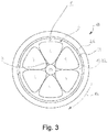
- Variants of such a data cable 18 are in the Fig. 3 and 4 shown. This is due to the special shape and arrangement of the outer wires 4 particularly homogeneous distributions of current and voltage, which are guided by means of the stranded conductor 2. The risk of partial discharges is significantly reduced as well as the resistance to the current, resulting in lower overall losses.
- data cable 18 is formed as a coaxial cable and has a stranded conductor 2, with a plurality of outer wires 4 as in Fig. 1 , In the center Z here, however, no inner wire 6 is arranged, but a functional element 20.
- a functional element 20 This is designed for example as a strain relief and then an aramid fiber or a steel cable.
- the functional element 20 is a latent heat storage.
- a thermal buffer on a polymer basis is used.
- the stranded conductor 2 is in turn surrounded by the insulation 12, which is also a dielectric 22 of the data cable 18 at the same time. Stranded conductor 2 and the dielectric form the data conductor 1. Surrounding the dielectric 22 is a shield 24, e.g. a screen foil, a braid or a banding. The shield 24 is in turn surrounded by an outer jacket 26.
- the particularly round peripheral contour of the stranded conductor 2, the distance between the outer wires 4 and the shield 24 in the circumferential direction is particularly homogeneous, so has a particularly low variance, whereby the transmission characteristics of the data cable 18 are significantly improved.
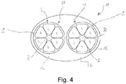
- a further data cable 18 is shown, which is formed here two wires, ie with two stranded conductors 2. These were dispensed both on an inner wire 6 and on a functional element 20, so that there is a void in the center Z.
- the outer wires 4 are each surrounded by an insulation 12, so that a total of two wires 28 are formed. These are combined in a common outer shell 26.
- the two wires 28 are each additionally shielded or alternatively or additionally, both wires 26 are surrounded by a common shield to form a shielded wire pair.
- the two wires 28 are either stranded together in a "twisted pair" or as "undistorted pair" parallel to each other.
- the omission of the inner wire in the center Z has the advantage, especially during assembly, that a crimp fastened to a respective wire 28 divides the stranded conductor 2 symmetrically, i. the even number of outer wires 4 is distributed evenly during crimping on the two sub-chambers of the crimp. This results in a particularly uniform mechanical load.
- the data cable 18 is lighter overall and requires less material for manufacturing.
Landscapes
- Insulated Conductors (AREA)
- Communication Cables (AREA)
Abstract
Die Erfindung betrifft ein Datenkabel mit einem Datenleiter (1), welcher einen von einer Isolierung (12) umgebenen Litzenleiter (2) aufweist, wobei der Litzenleiter (2) einen unverpressten Verbund aus mehreren Einzeldrähten (4) aufweist, welche gleichartig und als Außendrähte (4) ausgebildet sind und welche um ein Zentrum (Z) herum angeordnet sind, wobei die Außendrähte (4) mit einem unrunden Querschnitt ausgebildet sind, sodass im Querschnitt betrachtet die Ausdehnung der Außendrähte (4) vom Zentrum (Z) ausgehend radial nach außen zunimmt. Durch den speziell geformten Litzenleiter (2) werden die Übertragungseigenschaften des Datenkabels deutlich verbessert. Weiterhin betrifft die Erfindung einen entsprechenden Litzenleiter.The invention relates to a data cable having a data conductor (1) which has a stranded conductor (2) surrounded by an insulation (12), wherein the stranded conductor (2) has an unpressed composite of a plurality of individual wires (4) which are similar and external wires ( 4) are formed and which are arranged around a center (Z) around, wherein the outer wires (4) are formed with a non-circular cross section, so viewed in cross section, the extension of the outer wires (4) from the center (Z), starting radially increasing outwards , The specially shaped stranded conductor (2) significantly improves the transmission characteristics of the data cable. Furthermore, the invention relates to a corresponding stranded conductor.
Description
Die Erfindung betrifft ein Datenkabel sowie einen Litzenleiter.The invention relates to a data cable and a stranded conductor.
In der
Ein Datenkabel dient vorrangig der Signalübertragung, welche häufig bei hohen Frequenzen z.B. im GHz-Bereich erfolgt. Bei einem für das Datenkabel verwendeten Leiter erfolgt dann die Stromführung aufgrund des Skineffekts hauptsächlich am Außenumfang des Leiters. Bei einem Litzenleiter besteht nunmehr das Problem, dass der Außenumfang aufgrund der mehreren zusammengefassten Einzeldrähte nicht kreisrund ist und dadurch unvermeidbar Varianzen und Störstellen vorliegen, welche sich insgesamt negativ auf die Übertragungseigenschaften bei der Signalübertragung auswirken und speziell zu einer hohen Signaldämpfung führen.A data cable is primarily for signal transmission, often at high frequencies e.g. in the GHz range. In the case of a conductor used for the data cable, the current conduction then takes place mainly on the outer circumference of the conductor due to the skin effect. In the case of a stranded conductor, the problem now is that the outer circumference is not circular owing to the plurality of combined individual wires and as a result unavoidable variances and impurities are present, which have an overall negative effect on the transmission characteristics during signal transmission and lead to a high signal attenuation.
Vor diesem Hintergrund ist es eine Aufgabe der Erfindung, ein Datenkabel mit verbesserten Übertragungseigenschaften anzugeben. Weiterhin soll ein hierfür geeigneter Litzenleiter angegeben werden.Against this background, it is an object of the invention to provide a data cable with improved transmission characteristics. Furthermore, a suitable stranded conductor is to be specified.
Die Aufgabe wird erfindungsgemäß gelöst durch ein Datenkabel mit den Merkmalen gemäß Anspruch 1 sowie durch einen Litzenleiter mit den Merkmalen gemäß Anspruch 14. Vorteilhafte Ausgestaltungen, Weiterbildungen und Varianten sind Gegenstand der Unteransprüche. Dabei gelten die Ausführungen im Zusammenhang mit dem Datenkabel sinngemäß auch für den Litzenleiter.The object is achieved by a data cable with the features of
Das Datenkabel dient vorrangig zur Übertragung von Signalen, d.h. Daten, beispielsweise bei hohen Frequenzen im Bereich zwischen einigen 100 kHz, insbesondere 1 MHz, und 100 GHz. Das Datenkabel weist einen Litzenleiter auf, welcher einen unverpressten Verbund aus mehreren Einzeldrähten aufweist. Diese Einzeldrähte sind gleichartig und als Außendrähte ausgebildet und um ein Zentrum herum angeordnet. Dabei sind die Außendrähte mit einem unrunden Querschnitt ausgebildet, d.h. mit einer unrunden Querschnittsform, sodass im Querschnitt betrachtet die Ausdehnung der Außendrähte vom Zentrum ausgehend radial nach außen zunimmt. Die Einzeldrähte, welche als Außendrähte für einen entsprechenden Litzenleiter bestimmt sind, werden insbesondere mit einem unrunden Querschnitt vorgefertigt und als solche um das Zentrum herum angeordnet, d.h. die Außendrähte werden bereits mit einem unrunden Querschnitt verseilt.The data cable is primarily for transmission of signals, i. Data, for example at high frequencies in the range between a few 100 kHz, in particular 1 MHz, and 100 GHz. The data cable has a stranded conductor, which has a non-compressed composite of a plurality of individual wires. These individual wires are similar and designed as outer wires and arranged around a center. In this case, the outer wires are formed with a non-circular cross-section, i. with a non-circular cross-sectional shape, so viewed in cross-section, the expansion of the outer wires starting from the center increases radially outward. The individual wires, which are intended as outer wires for a corresponding stranded conductor, are prefabricated in particular with a non-circular cross-section and arranged as such around the center, i. the outer wires are already stranded with a non-circular cross-section.
Durch die Verwendung des speziell geformten Litzenleiters sind die Übertragungseigenschaften des Datenkabels deutlich verbessert. Wesentlich ist hierbei die Annäherung des Außenumfangs des Litzenleiters an eine Kreisform. Die Außendrähte sind jeweils speziell geformte Segmente, welche zusammengesetzt in guter Näherung einen ringförmigen Verbund bilden. Durch die unrunde Ausgestaltung weist ein jeweiliger Außendraht gemeinsam mit einem gedachten Umkreis um den gesamten Litzenleiter herum vorteilhaft mehrere Berührungspunkte auf und nicht lediglich einen, wie bei runden Einzeldrähten eines herkömmlichen Litzenleiters. Die zwischen den Einzeldrähten am Außenumfang gebildeten Zwickel sind deutlich kleiner, sodass sich in Umlaufrichtung um den Litzenleiter herum eine besonders geringe Varianz im Durchmesser ergibt. Die Wirkung der Zwickel als Störstellen bei der Signalübertragung ist entsprechend reduziert.By using the specially shaped stranded conductor, the transmission characteristics of the data cable are significantly improved. Essential here is the approximation of the outer circumference of the stranded conductor to a circular shape. The outer wires are each specially shaped segments, which form a ring-shaped composite to a good approximation. Due to the non-circular configuration, a respective outer wire together with an imaginary circumference around the entire stranded conductor around advantageously a plurality of points of contact and not just one, as in round individual wires of a conventional stranded conductor. The gussets formed between the individual wires on the outer circumference are significantly smaller, so that there is a particularly small variance in diameter in the direction of rotation around the stranded conductor. The effect of the gussets as impurities in the signal transmission is reduced accordingly.
Ein weiterer Vorteil besteht insbesondere darin, dass bei der Signalübertragung die Stromverteilung im speziell geformten Litzenleiter homogener ist. Allgemein nimmt die Stromdichte von innen nach außen hin zu und erreicht an den äußersten Punkten des Litzenleiters ein Maximum. Durch die Annäherung an eine Kreisform ist die Stromdichte im Außenbereich entlang des Außenumfangs deutlich besser verteilt und somit homogener, wodurch letztendlich eine geringere Signaldämpfung erzielt wird.Another advantage is, in particular, that during the signal transmission, the current distribution in the specially shaped stranded conductor is more homogeneous. In general, the current density increases from the inside to the outside and reaches a maximum at the outermost points of the stranded conductor. By approaching a circular shape For example, the external current density is much better distributed and therefore more homogeneous, which ultimately results in lower signal attenuation.
Besonders vorteilhaft ist weiterhin, dass der Weg vom radial äußersten Punkt eines Außenleiters hin zum Berührungspunkt mit einem benachbarten Außenleiter verringert ist. Dies ist insbesondere bei Hochfrequenzleitungen von Bedeutung, da hier ein Stromfluss nicht zwangsläufig lediglich in den Einzeldrähten erfolgt, sondern vielmehr auch zwischen den Einzeldrähten erfolgen kann. Entlang der hierbei vom Strom zurückzulegenden Strecke ergibt sich ein Verlust, welcher durch die spezielle Form der Außenleiter auf vorteilhafte Weise reduziert ist. Ein weiterer Verlust ergibt sich am Berührungspunkt zweier Außendrähte. Dieser Verlust ist von der Kontaktfläche zwischen den Außendrähten abhängig und bei kreisrunden Einzeldrähten entsprechend groß. Demgegenüber ist vorliegend die Kontaktfläche vergrößert und der Verlust entsprechend reduziert. Insgesamt sind demnach beim vorliegenden Datenkabel die Verluste, welche sich üblicherweise besonders für hochfrequente Signale ergeben, deutlich reduziert.It is furthermore particularly advantageous that the path from the radially outermost point of an outer conductor to the point of contact with an adjacent outer conductor is reduced. This is particularly important in high-frequency lines of importance, since a current flow is not necessarily only in the individual wires, but rather can also be done between the individual wires. Along the distance to be covered by the current, this results in a loss, which is advantageously reduced by the special shape of the outer conductor. Another loss results at the point of contact of two outer wires. This loss is dependent on the contact area between the outer wires and correspondingly large for circular individual wires. In contrast, in the present case, the contact area is increased and the loss is reduced accordingly. Overall, therefore, in the present data cable, the losses, which usually arise especially for high-frequency signals, significantly reduced.
Die spezielle Form und Anordnung der Außendrähte weist zudem Vorteile hinsichtlich der Spannungsverteilung im Litzenleiter auf. Durch die generell rundere Ausgestaltung sowohl der einzelnen Einzeldrähte als auch des gesamten Verbunds der Einzeldrähte ist die Spannungsverteilung insgesamt homogener. Die Gefahr von Teilentladungen ist deutlich reduziert, d.h. das Datenkabel weist eine verbesserte Teilentladungsfestigkeit auf. Bei herkömmlichen Litzenleitern wird zuweilen zur Feldsteuerung eine zusätzliche leitfähige Innenschicht innerhalb des Verbunds angeordnet. Auf eine solche kann vorliegend verzichtet werden und wird vorteilhafterweise auch verzichtet.The special shape and arrangement of the outer wires also has advantages in terms of stress distribution in the stranded conductor. Due to the generally rounder design of both the individual individual wires and the entire composite of the individual wires, the stress distribution is overall more homogeneous. The risk of partial discharges is significantly reduced, i. The data cable has an improved partial discharge resistance. In conventional stranded conductors, an additional conductive inner layer is sometimes placed within the composite for field control. In the present case, such can be dispensed with and advantageously also dispensed with.
Der Verbund aus Einzeldrähten ist im fertiggestellten Litzenleiter unverpresst, wird also nicht erst nachträglich durch ein Verpressen oder durch eine Kompaktierung aus ursprünglich runden Einzeldrähten in die unrunde Geometrie verformt. Der unrunde Querschnitt der Außendrähte ist dabei so gewählt, dass der gegebene Raum oder Platz möglichst vollständig ausgenutzt wird und dass der Querschnitt des Verbunds zumindest im Umfangsbereich, d.h. entlang der Umfangskontur möglichst kreisrund ist. Hierdurch sind die umfangsseitig verbleibenden Zwickel zumindest deutlich reduziert im Vergleich zu runden Einzeldrähten.The composite of individual wires is not pressed in the finished stranded conductor, so it is not subsequently deformed by compression or by compaction of originally round individual wires in the non-circular geometry. The non-circular cross section of the outer wires is chosen so that the given space or space is used as fully as possible and that the cross section of the composite at least in the peripheral region, that is as circular as possible along the peripheral contour. As a result, the circumferentially remaining gussets are at least significantly reduced in comparison to round individual wires.
Da der Verbund nicht verpresst wird und somit keiner nachträglichen Kompaktierung und daher keiner Kaltverformung unterzogen wird, kann und wird bei der Herstellung des Litzenleiters auf einen im Falle einer Kompaktierung üblichen Glühprozess für den Verbund verzichtet, sodass die Fertigung entsprechender Litzenleiter weniger aufwendig ist. Zudem weist ein solcher unverpresster Verbund aus Einzeldrähten eine hohe Wechselbiegebeständigkeit auf, was für eine Vielzahl von Anwendungen von Vorteil ist. Unter einer hohen Wechselbiegebeständigkeit oder Biegewechselbeständigkeit wird dabei verstanden, dass der Litzenleiter relativ vielen Biegewechselprozessen standhält, also geringe Ermüdungserscheinungen bei einer Biegewechselbeanspruchung zeigt. Für eine weitergehende Begriffserläuterung sei an dieser Stelle auf die ASTM B470 und die Veröffentlichung "
Diese hohe Wechselbiegebeständigkeit wird im Vergleich zu einem kompaktierten Litzenleiter gerade durch den Verzicht auf den Kompaktierschritt und der gleichzeitigen Verwendung von im Ausgangszustand vor dem Verlitzen unrunden Einzeldrähten erreicht. Die Einzeldrähte liegen nämlich - im Vergleich zu kompaktierten Litzenleiter - vergleichsweise lose aneinander an, so dass sie reibungsarm relativ zueinander beweglich sind. Im Unterschied hierzu sind die Einzeldrähte beim kompaktierten Litzenleiter durch die Kompaktierung derart verformt, dass sie flächig aneinander gepresst und dadurch quasi miteinander an ihren Oberflächen verzahnt sind. Gleichzeitig wird der Vorteil von kompaktierten Litzenleitern beibehalten, nämlich eine möglichst runde Umfangskontur zu erhalten.This high alternating bending resistance is achieved in comparison to a compacted stranded conductor just by dispensing with the compacting step and the simultaneous use of non-circular individual wires in the initial state before stranding. The individual wires are in fact - compared to compacted stranded conductor - comparatively loosely against each other, so that they are friction relative to each other. In contrast to this, the individual wires in the compacted stranded conductor are deformed by the compaction in such a way that they are pressed against one another in a flat manner and thus are practically interlocked with one another at their surfaces. At the same time the advantage of compacted stranded conductors is maintained, namely to obtain a round as possible peripheral contour.
Ein derartiger Litzenleiter wird insbesondere als superdünne Leitung, insbesondere Fahrzeugleitung eingesetzt.Such a stranded conductor is used in particular as a super-thin line, in particular vehicle line.
In einer bevorzugten Ausgestaltung ist der Datenleiter von einer Schirmung umgeben. Die Schirmung umgibt in einer Variante lediglich den Datenleiter oder alternativ auch mehrere oder alle Datenleiter gemeinsam. Die Schirmung ist beispielsweise als Folie, Bandierung oder Geflecht ausgebildet. Aufgrund der besonders runden Form des Litzenleiters ergibt sich in Umlaufrichtung auch ein besonders gleichmäßiger Abstand zwischen dem Litzenleiter und der Schirmung, wodurch die Übertragungseigenschaften des Datenkabels insgesamt weiter verbessert sind.In a preferred embodiment, the data conductor is surrounded by a shield. The shield surrounds in a variant only the data conductor or alternatively also several or all data conductors together. The shield is formed, for example, as a film, banding or braid. Due to the particularly round shape of the stranded conductor results in the direction of rotation also a particularly uniform distance between the stranded conductor and the shield, whereby the transmission characteristics of the data cable are further improved overall.
In einer geeigneten Weiterbildung ist der Datenleiter konzentrisch von der Schirmung umgeben und bildet mit dieser ein Koaxialkabel aus. Der Abstand zwischen dem Litzenleiter, d.h. einer Umfangskontur des Litzenleiters, und der Schirmung ist in Umlaufrichtung besonders homogen.In a suitable development of the data conductor is concentrically surrounded by the shield and forms with this a coaxial cable. The distance between the stranded conductor, i. a circumferential contour of the stranded conductor, and the shield is particularly homogeneous in the direction of rotation.
Alternativ zu der Ausgestaltung als Koaxialkabel bildet der Datenleiter eine Ader aus und vorzugsweise sind mehrere Adern zu einem Verbund zusammengeschlossen. Insbesondere bilden mehrere Ader einen Verseilverbund. Gemäß einer ersten Variante bilden zwei Adern ein Adernpaar, welches vorzugsweise von einer Paarschirmung umgeben ist. Das Adernpaar ist vorzugsweise verseilt und bildet dann ein sogenanntes "twisted pair" aus welches nicht zwingend von einer Paarschirmung umgeben sein muss. Alternativ sind die Adern des Paares parallel geführt und bilden ein untwisted pair" aus.As an alternative to the configuration as a coaxial cable, the data conductor forms a core and preferably several cores are combined to form a composite. In particular, several veins form a stranded composite. According to a first variant, two wires form a pair of wires, which is preferably surrounded by a pair shielding. The pair of wires is preferably stranded and then forms a so-called "twisted pair" which does not necessarily have to be surrounded by a pair shielding. Alternatively, the wires of the pair are routed in parallel and form an undistorted pair.
Auch bei einem Adernpaar ist die besonders runde Umfangskontur der Litzenleiter von Vorteil, da hierdurch auch der Abstand zwischen den beiden Litzenleitern des Adernpaars besonders gleichmäßig ist. Besonders bei miteinander verseilten Adern, welche umeinander herum verlaufen, ergibt sich aufgrund der besonders runden Umfangskontur entlang der gesamten Länge des Adernpaars ein besonders gleichmäßiger Abstand zwischen den beiden Adern.Even with a pair of wires, the particularly round peripheral contour of the stranded conductor is advantageous, since in this way the distance between the two stranded conductors of the pair of wires is particularly uniform. Especially with stranded wires, which run around each other, results in a particularly uniform distance between the two wires due to the particularly round peripheral contour along the entire length of the wire pair.
Alternativ zur paarweisen Anordnung können die Adern auch in einem Viererverseilverbund, beispielsweise in einem sogenannten Sternvierer angeordnet sein. Die Isolierung ist entweder jeweils einzeln auf die Litzenleiter aufgebracht oder als gemeinsame Isolierung ausgeführt. Die Isolierung besteht beispielsweise aus einem Kunststoff und ist aufextrudiert.As an alternative to pairwise arrangement, the wires can also be arranged in a quadruple compound, for example in a so-called star quad. The insulation is either individually applied to the stranded conductor or designed as a common insulation. The insulation consists for example of a plastic and is extruded.
Grundsätzlich ist es denkbar, die Außendrähte gemeinsam um einen zentralen Leiter, nachfolgend als Zentralleiter bezeichnet, anzuordnen, welcher im Zentrum angeordnet ist und insbesondere ebenfalls als Einzeldraht, d.h. dann als Innendraht ausgebildet ist. In einer solchen geeigneten Variante ist der Zentralleiter dann vorzugsweise kreisrund. Die Einzeldrähte sind vorteilhafterweise an den jeweiligen Anwendungszweck angepasst. Bei einem zweilagigen Litzenleiter mit einem Zentralleiter und einer Außenlage aus Außendrähten besteht dieser bevorzugt aus dem einen Zentralleiter und mehreren, insbesondere sechs Außendrähten. Bei Litzenleitern mit mehreren Außenlagen ist zumindest die äußerste Lage aus den Außendrähten mit dem unrunden Querschnitt gebildet. Die Außendrähte umgeben in diesem Fall das Zentrum mittelbar unter Zwischenanordnung von ein oder mehreren Zwischenlagen an Einzeldrähten, die rund oder vorzugsweise ebenso wie die äußersten Außendrähte unrund ausgebildet sind.In principle, it is conceivable to arrange the outer wires together around a central conductor, hereinafter referred to as central conductor, which is arranged in the center and in particular also as a single wire, i. then formed as an inner wire. In such a suitable variant, the central conductor is then preferably circular. The individual wires are advantageously adapted to the particular application. In a two-ply stranded conductor with a central conductor and an outer layer of outer wires, this preferably consists of the one central conductor and a plurality, in particular six outer wires. In stranded conductors with a plurality of outer layers at least the outermost layer of the outer wires is formed with the non-circular cross-section. The outer wires in this case surround the center indirectly with the interposition of one or more intermediate layers of individual wires, which are round or preferably formed out of round as well as the outermost outer wires.
In einer besonders bevorzugten Variante ist der Litzenleiter allerdings frei von einem Zentralleiter, d.h. im Zentrum ist kein Leiter angeordnet. Dem liegt zunächst die Überlegung zugrunde, dass die spezielle Form und Anordnung der Außendrähte auch in struktureller Hinsicht Vorteile aufweist. Im Querschnitt bilden die Außendrähte nämlich jeweils Segmente, welche sich gegenseitig gewölbeartig stützen, sodass im Zentrum kein Trage- oder Stützelement benötigt wird und zweckmäßigerweise auf ein solches verzichtet wird. Besonders in Kombination mit einer Verseilung der Außendrähte miteinander werden Kräfte, welche auf den Verbund wirken, in Längsrichtung des Litzenleiters umgelenkt. Im Gegensatz zu üblichen Litzenleitern wird dann der Innendraht eingespart und auf diese Weise eine Materialeinsparung erzielt. Des Weiteren wird eine Gewichtsreduktion erzielt, insbesondere im Bereich von etwa 3 bis 8% gegenüber herkömmlichen Litzenleitern. Auch bei einem Litzenleiter mit mehreren Lagen an Außendrähten ist ein leeres Zentrum, d.h. ein Weglassen des Innendrahts vorteilhaft.In a particularly preferred variant, however, the stranded conductor is free of a central conductor, ie no conductor is arranged in the center. This is based initially on the consideration that the special shape and arrangement of the outer wires also has structural advantages. In cross section, the outer wires namely each form segments which support each other like a vault, so that no support or support element is needed in the center and expediently waived such. Especially in combination with a stranding of the outer wires together, forces acting on the composite are deflected in the longitudinal direction of the stranded conductor. In contrast to conventional stranded conductors then the inner wire is saved and achieved in this way a material saving. Furthermore, a weight reduction is achieved, in particular in the range of about 3 to 8% compared to conventional stranded conductors. Even with a stranded conductor with several layers of outer wires, an empty center, ie an omission of the inner wire is advantageous.
Die Variante ohne Innendraht, insbesondere mit einem Hohlraum oder Leerraum im Zentrum, ist besonders hinsichtlich einer Konfektionierung des Datenkabels vorteilhaft. Beim Vercrimpen wird der Litzenleiter endseitig in einem Crimp verquetscht. Bei einem üblichen B-förmigen Crimp mit zwei Armen werden diese in den Litzenleiter hineingedrückt und bilden zwei Kammern, auf welche die Einzeldrähte verteilt werden. Bei einem üblichen Litzenleiter mit einer 6+1-Geometrie, d.h. mit einem Innendraht, ergibt sich zwangsläufig eine ungleiche Verteilung, wohingegen bei fehlendem Innendraht die sechs Außendrähte gleichmäßig verteilt werden, wodurch sich vorteilhaft eine homogenere mechanische Belastung ergibt. Diese Ausgestaltung mit dem Hohlraum im Zentrum ist grundsätzlich auch für Litzenleiter einsetzbar, die nicht für Datenleiter verwendet sind.The variant without inner wire, in particular with a cavity or empty space in the center, is particularly advantageous with regard to a packaging of the data cable. When crimping the stranded conductor is crimped end in a crimp. In a conventional B-shaped crimp with two arms, these are pressed into the stranded conductor and form two chambers, on which the individual wires are distributed. In a conventional stranded conductor having a 6 + 1 geometry, i. with an inner wire inevitably results in an unequal distribution, whereas in the absence of inner wire, the six outer wires are evenly distributed, resulting in a more advantageous homogeneous mechanical load. This embodiment with the cavity in the center can in principle also be used for stranded conductors which are not used for data conductors.
In einer vorteilhaften Alternative ist im Zentrum des Litzenleiters ein Funktionselement angeordnet, insbesondere anstelle eines Innendrahts. Dem Zentrum wird dadurch auf vorteilhafte und platzsparende Weise eine alternative Verwendung zugewiesen. Das Funktionselement ist dann insbesondere zentral geführt und gleichmäßig von den Außendrähten umgeben. In dieser Variante bilden die Außendrähte vorteilhaft einen mechanischen Schutz für das innenliegende Funktionselement.In an advantageous alternative, a functional element is arranged in the center of the stranded conductor, in particular instead of an inner wire. The center is thereby assigned an alternative use in an advantageous and space-saving manner. The functional element is then guided in particular centrally and uniformly surrounded by the outer wires. In this variant, the outer wires advantageously form a mechanical protection for the inner functional element.
In einer geeigneten Weiterbildung ist das Funktionselement als Zugentlastung ausgebildet. Dadurch ist der Litzenleiter besonders robust hinsichtlich einer Zugbelastung entlang der Längsrichtung. Das Funktionselement ist hierbei beispielsweise ein Stahldraht oder ein zugfester Trägerfaden, beispielsweise aus Aramid, oder Polyamid.In a suitable development, the functional element is designed as a strain relief. As a result, the stranded conductor is particularly robust with respect to a tensile load along the longitudinal direction. The functional element here is, for example, a steel wire or a tension-resistant carrier thread, for example made of aramid, or polyamide.
In einer alternativen geeigneten Weiterbildung ist das Funktionselement als Latentwärmespeicher ausgebildet. In dieser Ausgestaltung kann das Datenkabel im Betrieb Temperaturspitzen besonders gut abfangen, indem Wärme in dem Funktionselement gespeichert wird. Dieses wird dann zu einem späteren Zeitpunkt wieder regeneriert und dabei die Wärme wieder abgegeben. Der Latentwärmespeicher wirkt somit als thermischer Zwischenspeicher und ist beispielsweise aus einem Material auf Polymerbasis gefertigt. Ein geeigneter Latentwärmespeicher ist beispielsweise in der
Die diversen Varianten des Funktionselements lassen sich selbstverständlich auch miteinander kombinieren. Ebenso sind auch weitere Varianten denkbar. Beispielsweise wird alternativ oder zusätzlich als Funktionselement eine optische Faser verwendet. Auch ein gegenüber den Außendrähten isolierter Innendraht ist als Funktionselement prinzipiell geeignet.The various variants of the functional element can of course be combined with each other. Likewise, other variants are conceivable. For example, an optical fiber is alternatively or additionally used as a functional element. Also, an insulated against the outer wires inner wire is suitable in principle as a functional element.
Wie bereits erwähnt weisen die vorgeformten Einzeldrähte jeweils eine Querschnittsform derart auf, dass der Querschnitt des gesamten Verbunde möglichst rund ist und somit einem Kreis möglichst nahe kommt. Im einfachsten Fall wird dabei für die Außendrähte eine an eine dreieckige Querschnittsform zumindest angenäherte Querschnittsform gewählt, wobei die Form eines gleichseitigen Dreiecks bevorzugt ist. Im Verbund sind die Außendrähte dann derart angeordnet, dass im Querschnitt betrachtet eine Ecke eines jeden Außendrahtes radial nach innen in Richtung zum Zentrum zeigt. Bei Verwendung eines Innendrahts oder eines Funktionselements liegen die Außendrähte dann quasi punktförmig am Innendraht bzw. am Funktionselement an; bei Verwendung einer Zwischenlage zwischen den Außendrähten und dem Zentrum entsprechend an der Zwischenlage. Zwischen den Außendrähten und dem Zentrum ist somit allgemein im Wesentlichen eine Punktauflage realisiert, aufgrund welcher eine hohe Flexibilität und eine hohe Wechselbiegebeständigkeit des Verbunds und letzten Endes auch des Litzenleiters sowie des Datenkabels insgesamt gegeben ist. Im Unterschied hierzu sind bei kompaktierten Litzenleitern im Querschnitt betrachtet, d.h. quer zur Längsrichtung linienförmige Kontaktzonen gebildet. Insbesondere sind dabei die Einzeldrähte in etwa nach Art eines Trapezes ausgebildet, wobei insbesondere die zum Innendraht orientierte Trapezfläche konkav gewölbt ist und sich an die Rundung des Innendrahts anschmiegt.As already mentioned, the preformed individual wires each have a cross-sectional shape such that the cross section of the entire composite is as round as possible and thus comes as close as possible to a circle. In the simplest case, a cross-sectional shape at least approximated to a triangular cross-sectional shape is selected for the outer wires, the shape of an equilateral triangle being preferred. In combination, the outer wires are then arranged such that viewed in cross section, a corner of each outer wire points radially inward toward the center. When using an inner wire or a functional element, the outer wires are then virtually point-like on the inner wire or on the functional element; when using an intermediate layer between the outer wires and the center corresponding to the intermediate layer. Between the outer wires and the center is thus generally realized essentially a point support, due to which a high flexibility and high resistance to bending of the composite and ultimately also the stranded conductor and the data cable is given as a whole. In contrast, in compacted stranded conductors, viewed in cross section, i. formed linear contact zones transversely to the longitudinal direction. In particular, the individual wires are formed approximately in the manner of a trapezoid, wherein in particular the oriented to the inner wire trapezoidal surface is concave and conforms to the rounding of the inner wire.
Zweckdienlicherweise wird für die Außendrähte eine dreieckige Querschnittsform gewählt, bei der die Ecken abgerundet sind, d.h. die Querschnittsform weist abgerundete Ecken auf. Eine derartige Querschnittsform lässt sich unter anderem leichter realisieren.Conveniently, a triangular cross-sectional shape is selected for the outer wires, in which the corners are rounded, ie the cross-sectional shape has rounded Corners on. Such a cross-sectional shape can be more easily realized, among other things.
In vorteilhafter Weiterbildung sind die Seiten des dreieckigen Querschnitts nach außen gewölbt und somit bogenförmig gestaltet, d.h. die Querschnittsform der Außendrähte weist abgerundete Ecken auf. Auf diese Weise berühren sich die Außendrähte untereinander quasi punktuell, was wiederum eine hohe Flexibilität und eine hohe Wechselbiegebeständigkeit des Verbundes nach sich zieht. Dennoch ist die Bogenform insbesondere durch einen Radius charakterisiert, welcher größer ist als der Radius eines üblichen kreisrunden Einzeldrahts, sodass die tatsächliche Kontaktfläche zweier benachbarter Außendrähte größer ist, als bei einem herkömmlichen Litzenleiter.In an advantageous embodiment, the sides of the triangular cross-section are arched outwards and thus arc-shaped, i. the cross-sectional shape of the outer wires has rounded corners. In this way, the outer wires touch each other quasi selectively, which in turn attracts a high flexibility and high resistance to bending of the composite. Nevertheless, the arc shape is characterized in particular by a radius which is greater than the radius of a conventional circular single-wire, so that the actual contact surface of two adjacent outer wires is greater than in a conventional stranded conductor.
Bevorzugt wird des Weiteren eine Ausführung des Litzenleiters, bei welcher die Außendrähte eine Querschnittsform nach Art eines Reuleaux-Dreiecks mit abgerundeten Ecken aufweisen. Eine derart gestaltete Querschnittsform zeichnet sich durch konvex nach außen gewölbte Seitenflächen sowie abgerundete Ecken aus. Sowohl an den Seitenflächen als auch an den Ecken liegen die Einzeldrähte daher im Querschnitt betrachtet an benachbarten Litzenleiter nur punktförmig an. Diese Ausgestaltung ist im Hinblick auf die gewünschte hohe Biegewechselfähigkeit besonders vorteilhaft.Furthermore, an embodiment of the stranded conductor is preferred, in which the outer wires have a cross-sectional shape in the manner of a Reuleaux triangle with rounded corners. Such a shaped cross-sectional shape is characterized by convexly outwardly curved side surfaces and rounded corners. Both on the side surfaces and at the corners, the individual wires are therefore only punctiform in view of cross-section on adjacent stranded conductors. This embodiment is particularly advantageous in view of the desired high bending flexibility.
Für den Innendraht oder das Funktionselement wird hingegen ein runder Querschnitt bevorzugt.For the inner wire or the functional element, however, a round cross section is preferred.
Gemäß einer weiteren vorteilhaften Ausgestaltung des Litzenleiters sind die Außendrähte derart geformt und angeordnet, dass zwischen benachbarten Außendrähten in guter Näherung eine Punktauflage gegeben ist, d.h. jeweils zwei benachbarte Außendrähte berühren sich punktuell. Unter punktuell wird dabei insbesondere verstanden, dass die aneinander anliegenden Außendrähte am Berührungspunkt grundsätzlich gekrümmt, d.h. konvex ausgebildet sind, und sich dadurch im Querschnitt betrachtet lediglich an einem Punkt berühren. Infolgedessen bilden die Außendrähte zusammen eine das Zentrum umhüllende und einschließende Außenlage aus, welche im Querschnitt gesehen einen im Wesentlichen kreisförmigen Umfang zeigt.According to a further advantageous embodiment of the stranded conductor, the outer wires are shaped and arranged such that between adjacent outer wires in a good approximation, a point support is given, ie in each case two adjacent outer wires touch punctiform. By punctual is meant in particular that the abutting outer wires are basically curved at the point of contact, that is, convex, and thereby in cross-section touch only at one point. As a result, the outer wires together form a center enveloping and enclosing Outer layer of which, seen in cross-section shows a substantially circular circumference.
Alternativ berühren sich jeweils zwei benachbarten Außendrähte flächig, d.h. im Querschnitt betrachtet linienförmig. Hierbei ist die Kontaktfläche zwischen den Außendrähten vorteilhaft vergrößert, sodass sich verringerte Verluste bei der Übertragung von Signalen ergeben. Die flächige Berührung ergibt sich insbesondere nach dem Verlitzen dadurch, dass hierbei die Außendrähte zumindest leicht gegeneinandergedrückt werden. Zwischen zwei benachbarten Außendrähten ist dann eine im Querschnitt linienförmige, insbesondere gerade, Kontaktzone ausgebildet, d.h. in Längsrichtung des Litzenleiters ergibt sich eine entsprechende Kontaktfläche. Die Außendrähte liegen dabei aufgrund der generell gebogenen Umfangskontur nicht vollständig flächig aneinander an, sondern lediglich in jeweiligen Teilabschnitten der Umfangskonturen der Außendrähte. Dadurch ist ein optimaler Kompromiss zwischen einer guten Biege- Wechselbeständigkeit und einer großen, d.h. verlustarmen Kontaktzone realisiert ist. Im Querschnitt wird die Kontaktzone dann insbesondere durch die Zwickel begrenzt, und zwar insbesondere sowohl von innen als auch von außen.Alternatively, in each case two adjacent outer wires touch each other flat, i. viewed in cross-section linear. Here, the contact surface between the outer wires is advantageously increased, resulting in reduced losses in the transmission of signals. The surface contact results in particular after the stranding in that in this case the outer wires are at least slightly pressed against each other. Between two adjacent outer wires is then formed a cross-sectionally linear, in particular straight, contact zone, i. in the longitudinal direction of the stranded conductor results in a corresponding contact surface. Due to the generally curved peripheral contour, the outer wires do not lie completely flat against each other, but only in respective sections of the peripheral contours of the outer wires. This provides an optimal compromise between good bending cycle stability and a large, i. low-loss contact zone is realized. In cross section, the contact zone is then limited in particular by the gusset, in particular both from the inside and from the outside.
Die Außendrähte werden bevorzugt mit einer isolierenden Ummantelung oder Isolierung beispielsweise aus Kunststoff überzogen, wobei die Wandstärke der Isolierung aufgrund des nahezu kreisförmigen Umfangs der Außenlage in Umfangsrichtung gesehen nahezu gleichbleibend ist. Dadurch lässt sich vorteilhaft eine sehr dünne Wandstärke realisieren, sodass ein entsprechend gestalteter Litzenleiter ein verhältnismäßig geringes Gewicht und einen verhältnismäßig geringen Bauraumbedarf aufweist. Entsprechende Litzenleiter sind dabei insbesondere für den Kraftfahrzeugbereich vorgesehen und dementsprechend bevorzugt für diesen Anwendungszweck ausgelegt.The outer wires are preferably coated with an insulating sheath or insulation, for example made of plastic, wherein the wall thickness of the insulation due to the almost circular periphery of the outer layer is seen in the circumferential direction is almost constant. As a result, it is advantageously possible to realize a very thin wall thickness, so that a correspondingly designed stranded conductor has a relatively low weight and a relatively small space requirement. Corresponding stranded conductors are provided in particular for the motor vehicle sector and are accordingly preferably designed for this application.
Der Verbund aus Einzeldrähten weist vorteilhafterweise eine Querschnittsfläche kleiner 2,5 mm2 und insbesondere kleiner 1,5 mm2 auf. Die Querschnittsfläche ist insbesondere die Summe der Querschnittsformen der Außendrähte, d.h. das Zentrum ist ausgenommen. Bei zusätzlicher Verwendung eines Innendrahts, wird dieser entsprechend hinzugerechnet. Besonders verbreitet sind vor allem Querschnittsflächen von 0,35 mm2, 0,75 mm2 und 1 mm2, die auch vorliegend vorzugsweise verwendet sind.The composite of individual wires advantageously has a cross-sectional area of less than 2.5 mm 2 and in particular less than 1.5 mm 2 . The cross-sectional area is in particular the sum of the cross-sectional shapes of the outer wires, ie the center is excluded. With additional use of an inner wire, this will added accordingly. Especially widespread are cross-sectional areas of 0.35 mm 2 , 0.75 mm 2 and 1 mm 2 , which are also preferably used here.
Der Litzenleiter weist zweckdienlicherweise eine Schlaglänge auf, die bevorzugt 4 mm bis 30 mm beträgt. Dabei sind bei höheren Frequenzen geringere Schlaglängen vorteilhaft. Unter Schlaglänge wird die axiale Länge des Litzenleiters verstanden, die für eine 360°-Wicklung eines jeweiligen Einzeldrahtes benötigt wird. Im Unterschied zu herkömmlichen Litzen mit runden Einzeldrähten ist die Schlaglänge deutlich geringer, insbesondere etwa um den Faktor 2. Insbesondere ist die Schlaglänge auch zumindest weitgehend unabhängig von dem jeweiligen Durchmesser des Verbundes aus Einzeldrähten. Litzenleiter unterschiedlicher Durchmesser weisen daher gleiche oder zumindest vergleichbare Schlaglängen auf, die in dem angegebenen Bereich liegen. Bei herkömmlichen Verbünden variiert die Schlaglänge mit den Durchmessern. Untersuchungen haben ergeben, dass diese verkürzte Schlaglänge von besonderem Vorteil ist und ein unerwünschtes Verdrehen der unrunden Einzeldrähte um ihre Mittenachse aus der gewünschten Drehorientierung vermieden ist. Dadurch ist die definierte, gewünschte Ausrichtung der Einzeldrähte im Verbund sichergestellt.The stranded conductor expediently has a lay length, which is preferably 4 mm to 30 mm. Lower strike lengths are advantageous at higher frequencies. Impact length is understood to be the axial length of the stranded conductor which is required for a 360 ° winding of a respective individual wire. In contrast to conventional strands with round individual wires, the lay length is significantly lower, in particular approximately by a factor of 2. In particular, the lay length is also at least largely independent of the respective diameter of the composite of individual wires. Stranded conductors of different diameters therefore have identical or at least comparable lay lengths, which are within the stated range. In conventional assemblies, the lay length varies with diameters. Investigations have shown that this shortened lay length is of particular advantage and undesired twisting of the non-round individual wires about their center axis from the desired rotational orientation is avoided. This ensures the defined, desired alignment of the individual wires in the composite.
Auf der Basis der hier vorgestellten Grundidee, also der Verwendung von vorgeformten Einzeldrähten mit unrundem Querschnitt, lassen sich darüber hinaus auch Litzenleiter realisieren, die mehrere Lagen an Außendrähten aufweisen, wobei die einzelnen Lagen vorzugsweise konzentrisch zum Zentrum angeordnet sind. Auch bei diesen Litzenleitern lässt sich durch dieses Konzept eine bessere Raumausnutzung erreichen.On the basis of the basic idea presented here, ie the use of preformed individual wires with a non-circular cross-section, it is also possible to realize stranded conductors which have a plurality of layers on outer wires, wherein the individual layers are preferably arranged concentrically to the center. Even with these stranded conductors can be achieved by this concept, a better space utilization.
Unabhängig von der Anzahl der Lagen aus Außendrähten erfolgt im Rahmen der Herstellung entsprechender Litzenleiter zunächst eine Vorfertigung der Einzeldrähte mit unrundem Querschnitt, insbesondere durch einen üblicherweise mehrstufigen Ziehprozess. Nachfolgend werden die so in Form gebrachten Einzeldrähte bevorzugt einer Glühprozedur (Weichglühen) unterzogen, um die gewünschten biegeelastischen Eigenschaften der Einzeldrähte zu gewährleisten. In der Folge werden die Einzeldrähte dann verlitzt oder verseilt und schließlich mit der Isolierung versehen, wobei hierfür beispielsweise ein Extruder einer Verlitzmaschine unmittelbar nachgelagert ist. Eine Verpressung der Einzeldrähte oder des Verbundes aus Einzeldrähten sowie eine weitere Glühprozedur nach dem Verlitzen wird nicht vorgenommen.Regardless of the number of layers of outer wires is carried out in the context of producing corresponding stranded conductor first, a prefabrication of the individual wires with non-circular cross section, in particular by a usually multi-stage drawing process. Subsequently, the individual wires thus formed are preferably subjected to an annealing procedure (soft annealing) to ensure the desired flexural elastic properties of the individual wires. Subsequently the individual wires are then stranded or stranded and finally provided with the insulation, for which purpose, for example, an extruder of a Verlitzmaschine is immediately downstream. A compression of the individual wires or the composite of individual wires and a further annealing procedure after the stranding is not made.
Nachfolgend werden Ausführungsbeispiele der Erfindung anhand einer Zeichnung näher erläutert. Darin zeigen jeweils schematisch und im Querschnitt:
-
Fig. 1 einen Litzenleiter mit einem Innendraht und mit mehreren Außendrähten -
Fig. 2 in einer vergrößerten Querschnittsdarstellung einen der Außendrähte, -
Fig. 3 ein Datenkabel, und -
Fig. 4 eine Variante des Datenkabels.
-
Fig. 1 a stranded wire with an inner wire and with several outer wires -
Fig. 2 in an enlarged cross-sectional view of one of the outer wires, -
Fig. 3 a data cable, and -
Fig. 4 a variant of the data cable.
Ein nachfolgend exemplarisch beschriebener und in
Die Außendrähte 4 sind identisch, d.h. gleichartig gestaltet und weisen eine Querschnittsform auf, welche in guter Näherung der Form eines Reuleaux-Dreiecks mit abgerundeten Ecken entspricht. Diese Querschnittsform ist in
Bei einem Litzenleiter 2 für ultradünne Fahrzeugleitungen liegt die Seitenlänge L beispielsweise im Bereich von 0,25 mm - 0,6 mm, insbesondere bei etwa 0,4 mm. Der Radius RS beträgt etwa das 10-fache des Radius RE und liegt beispielsweise bei 0,6 mm bis 1 mm, insbesondere bei 0,8 mm.In a stranded
Der Verbund aus Außendrähten 4 und dem Innendraht 6 ist derart gestaltet, dass im Querschnitt betrachtet eine Ecke eines jeden Außendrahtes 4 punktuell am Innendraht 6 anliegt und dass zwischen benachbarten Außendrähten 4 ebenfalls eine Punktauflage, also eine punktuelle Berührung, gegeben ist.The composite of
Die Außendrähte 4 bilden zusammen eine geschlossene Außenlage 8 aus, durch die das Zentrum Z vollständig eingeschlossen ist. Die Außenlage 8 weist weiter im Querschnitt betrachtet eine in guter Näherung kreisförmige Umfangskontur auf, wobei jedoch jeweils im Zwischenbereich zwischen zwei Außendrähten 4 umfangsseitig ein verbleibender Zwickel 10 gebildet ist. Diese Zwickel 10 sind allerdings im Vergleich zu einem Litzenleiter nach dem Stand der Technik, bei dem Außendrähte mit einem kreisförmigen Querschnitt um einen Innendraht mit ebenfalls kreisförmigem Querschnitt angeordnet sind, verhältnismäßig klein.The
Der Datenleiter 1 weist außerdem eine die Außenlage umgebende Isolierung 12 auf, die üblicherweise durch eine Extrusion auf den Litzenleiter 2aufgebracht wird. Durch die gewählte Querschnittsform der Außendrähte 4 und die infolgedessen relativ geringe Größe der Zwickel 10 ist die Wandstärke 14 der Isolierung 12 in Umfangsrichtung 16 gesehen in guter Näherung gleichbleibend und kann insbesondere sehr dünn eingestellt werden.The
Aus den
Das in
Der Litzenleiter 2 ist wiederum von der Isolierung 12 umgeben, welche hier zugleich ein Dielektrikum 22 des Datenkabels 18 ist. Litzenleiter 2 und das Dielektrikum bilden den Datenleiter 1. Um das Dielektrikum 22 herum ist eine Schirmung 24 angeordnet, z.B. eine Schirmfolie, ein Geflecht oder eine Bandierung. Die Schirmung 24 ist wiederum von einem Außenmantel 26 umgeben. Durch die besonders runde Umfangskontur des Litzenleiters 2 ist der Abstand zwischen den Außendrähten 4 und der Schirmung 24 in Umfangsrichtung besonders homogen, weist also eine besonders geringe Varianz auf, wodurch die Übertragungseigenschaften des Datenkabels 18 deutlich verbessert sind.The stranded
In
Das Weglassen des Innendrahts im Zentrum Z hat besonders beim Konfektionieren den Vorteil, dass ein an einer jeweiligen Ader 28 befestigter Crimp den Litzenleiter 2 symmetrisch teilt, d.h. die gerade Anzahl an Außendrähten 4 wird beim Verquetschen gleichmäßig auf die zwei Teilkammern des Crimps verteilt. Dadurch ergibt sich eine besonders gleichmäßige mechanische Belastung. Zugleich ist das Datenkabel 18 insgesamt leichter und benötigt weniger Material zur Fertigung.The omission of the inner wire in the center Z has the advantage, especially during assembly, that a crimp fastened to a
Claims (14)
wobei der Datenleiter von einer Schirmung umgeben ist.Data cable according to the preceding claim,
wherein the data conductor is surrounded by a shield.
wobei dieses als Koaxialkabel ausgebildet ist, bei welchem der Litzenleiter und die Schirmung konzentrisch angeordnet sind.Data cable according to the preceding claim,
this is designed as a coaxial cable, in which the stranded conductor and the shield are arranged concentrically.
wobei dieses zwei Datenleiter aufweist, welche ein Aderpaar bilden.Data cable according to one of claims 1 or 2,
this having two data conductors which form a wire pair.
wobei der Litzenleiter frei von einem Zentralleiter ist.Data cable according to one of the preceding claims,
wherein the stranded conductor is free of a central conductor.
wobei im Zentrum des Litzenleiters ein Funktionselement angeordnet ist.Data cable according to one of the preceding claims,
wherein in the center of the stranded conductor, a functional element is arranged.
wobei das Funktionselement als Zugentlastung ausgebildet ist.Data cable according to the preceding claim,
wherein the functional element is designed as a strain relief.
wobei das Funktionselement als Latentwärmespeicher ausgebildet ist.Data cable according to claim 6,
wherein the functional element is designed as a latent heat storage.
wobei die Außendrähte jeweils eine dreieckige Querschnittsform aufweisen.Data cable according to one of the preceding claims,
wherein the outer wires each have a triangular cross-sectional shape.
wobei die Querschnittsform der Außendrähte abgerundete Ecken aufweist.Data cable according to the preceding claim,
wherein the cross-sectional shape of the outer wires has rounded corners.
wobei die Querschnittsform der Außendrähte nach außen gebogene Seiten aufweist.Data cable according to one of the two preceding claims,
wherein the cross-sectional shape of the outer wires has outwardly curved sides.
wobei sich jeweils zwei benachbarte Außendrähte punktuell berühren.Data cable according to one of the preceding claims,
wherein each two adjacent outer wires touch punctually.
wobei sich jeweils zwei benachbarte Außendrähte flächig berühren.Data cable according to one of claims 1 to 11,
in each case two adjacent outer wires touch each other surface.
Applications Claiming Priority (1)
| Application Number | Priority Date | Filing Date | Title |
|---|---|---|---|
| DE102016202791 | 2016-02-23 |
Publications (1)
| Publication Number | Publication Date |
|---|---|
| EP3211642A1 true EP3211642A1 (en) | 2017-08-30 |
Family
ID=57749841
Family Applications (1)
| Application Number | Title | Priority Date | Filing Date |
|---|---|---|---|
| EP17150367.5A Withdrawn EP3211642A1 (en) | 2016-02-23 | 2017-01-05 | Data cable and stranded conductor |
Country Status (3)
| Country | Link |
|---|---|
| US (1) | US10199144B2 (en) |
| EP (1) | EP3211642A1 (en) |
| CN (1) | CN107103946A (en) |
Families Citing this family (3)
| Publication number | Priority date | Publication date | Assignee | Title |
|---|---|---|---|---|
| US11289239B2 (en) * | 2018-02-20 | 2022-03-29 | Junkosha Inc. | Electric wire, cable harness and flying object |
| JPWO2022131258A1 (en) * | 2020-12-15 | 2022-06-23 | ||
| CN113192698B (en) * | 2021-03-26 | 2023-03-28 | 胜利油田胜利泵业有限责任公司 | Cable conductor stranding device for long stator winding of magnetic suspension train |
Citations (7)
| Publication number | Priority date | Publication date | Assignee | Title |
|---|---|---|---|---|
| DE961722C (en) * | 1951-02-23 | 1957-04-11 | Siemens Ag | Single conductor arrangement for the transmission of short and very short electromagnetic waves |
| JPS5561913U (en) * | 1978-10-24 | 1980-04-26 | ||
| JPS5883708U (en) * | 1981-12-02 | 1983-06-07 | 並木精密宝石株式会社 | Wire material for cables |
| JPH07153327A (en) * | 1993-11-29 | 1995-06-16 | Riken Densen Kk | Litz wire and manufacture thereof |
| DE102012014944A1 (en) | 2012-07-30 | 2014-01-30 | Leoni Kabel Holding Gmbh | Coaxial cable for high performance applications |
| JP2014096349A (en) * | 2012-10-11 | 2014-05-22 | Kanzacc Co Ltd | Litz wire |
| WO2015067717A1 (en) | 2013-11-06 | 2015-05-14 | Leoni Kabel Holding Gmbh | Stranded conductors and method for producing stranded conductors |
Family Cites Families (17)
| Publication number | Priority date | Publication date | Assignee | Title |
|---|---|---|---|---|
| US2197544A (en) * | 1938-08-05 | 1940-04-16 | Gen Cable Corp | Electric cable |
| US3586751A (en) * | 1969-04-07 | 1971-06-22 | Southwire Co | Circular electric service cable |
| JPS5883708A (en) | 1981-03-02 | 1983-05-19 | デイツカ−ホツフ・ウント・ウインドマン・アクチエンゲゼルシヤフト | Obliquely tensioned bridge |
| US4687884A (en) * | 1985-05-14 | 1987-08-18 | Aluminum Company Of America | Low drag conductor |
| US5260516A (en) * | 1992-04-24 | 1993-11-09 | Ceeco Machinery Manufacturing Limited | Concentric compressed unilay stranded conductors |
| US6307156B1 (en) * | 1997-05-02 | 2001-10-23 | General Science And Technology Corp. | High flexibility and heat dissipating coaxial cable |
| ITSV20040001A1 (en) * | 2004-01-12 | 2004-04-12 | Ultraflex Spa | MULTI-FILM HELICAL CABLE IN PARTICULAR FOR MECHANICAL MOVEMENT TRANSMISSION |
| CN101006527A (en) * | 2004-03-17 | 2007-07-25 | Gift技术有限合伙公司 | Electrical conductor cable and method for forming the same |
| US20050279527A1 (en) * | 2004-06-17 | 2005-12-22 | Johnson Douglas E | Cable and method of making the same |
| JP4143086B2 (en) * | 2005-12-20 | 2008-09-03 | 日立電線株式会社 | Extra-fine copper alloy wire, extra-fine copper alloy twisted wire, and manufacturing method thereof |
| FR2896911B1 (en) * | 2006-02-01 | 2008-03-21 | Nexans Sa | ELECTRICAL TRANSPORT CONDUCTOR FOR AERIAL LINE |
| CA2675253C (en) * | 2007-02-16 | 2016-02-23 | Nv Bekaert Sa | An improved steel core for an electric transmission cable and method of fabricating it |
| WO2011090133A1 (en) * | 2010-01-20 | 2011-07-28 | 古河電気工業株式会社 | Composite electric cable and process for producing same |
| EP2669900B1 (en) * | 2011-01-24 | 2015-07-29 | La Farga Lacambra, S.A. | Electrical conductor for transporting electrical energy and corresponding production method |
| WO2012142096A1 (en) * | 2011-04-12 | 2012-10-18 | Ticona Llc | Composite core for electrical transmission cables |
| US9859038B2 (en) * | 2012-08-10 | 2018-01-02 | General Cable Technologies Corporation | Surface modified overhead conductor |
| CN203013375U (en) * | 2012-11-17 | 2013-06-19 | 金杯电工衡阳电缆有限公司 | Five-core aluminum power cable |
-
2017
- 2017-01-05 EP EP17150367.5A patent/EP3211642A1/en not_active Withdrawn
- 2017-02-22 US US15/439,212 patent/US10199144B2/en active Active
- 2017-02-22 CN CN201710096211.3A patent/CN107103946A/en active Pending
Patent Citations (7)
| Publication number | Priority date | Publication date | Assignee | Title |
|---|---|---|---|---|
| DE961722C (en) * | 1951-02-23 | 1957-04-11 | Siemens Ag | Single conductor arrangement for the transmission of short and very short electromagnetic waves |
| JPS5561913U (en) * | 1978-10-24 | 1980-04-26 | ||
| JPS5883708U (en) * | 1981-12-02 | 1983-06-07 | 並木精密宝石株式会社 | Wire material for cables |
| JPH07153327A (en) * | 1993-11-29 | 1995-06-16 | Riken Densen Kk | Litz wire and manufacture thereof |
| DE102012014944A1 (en) | 2012-07-30 | 2014-01-30 | Leoni Kabel Holding Gmbh | Coaxial cable for high performance applications |
| JP2014096349A (en) * | 2012-10-11 | 2014-05-22 | Kanzacc Co Ltd | Litz wire |
| WO2015067717A1 (en) | 2013-11-06 | 2015-05-14 | Leoni Kabel Holding Gmbh | Stranded conductors and method for producing stranded conductors |
Non-Patent Citations (1)
| Title |
|---|
| SCHYMURA M.A.; FISCHER A., ASTM B470 - 02. METALL, vol. 66, no. 11, 2012, pages 514 - 517 |
Also Published As
| Publication number | Publication date |
|---|---|
| US10199144B2 (en) | 2019-02-05 |
| CN107103946A (en) | 2017-08-29 |
| US20170243678A1 (en) | 2017-08-24 |
Similar Documents
| Publication | Publication Date | Title |
|---|---|---|
| US5496969A (en) | Concentric compressed unilay stranded conductors | |
| CA2285932C (en) | Multi-wire sz and helical stranded conductor and method of forming same | |
| EP2823493B1 (en) | Method for producing a stranded inner conductor for coaxial cable, and coaxial cable | |
| DE102017210234A1 (en) | Bending resistant shielded composite cable and harness | |
| EP0619583B1 (en) | Electrical round cable | |
| EP3211642A1 (en) | Data cable and stranded conductor | |
| CH656970A5 (en) | HIGHLY FLEXIBLE INSULATED ELECTRIC CABLE, METHOD FOR THE PRODUCTION AND USE OF THE CABLE. | |
| EP3025356B1 (en) | Stranded conductors and method for producing stranded conductors | |
| EP3285266A1 (en) | Cable with adapted stranding | |
| WO2015128484A1 (en) | Cable core for a cable, in particular an induction cable, cable, and method for producing a cable core | |
| WO2017076984A1 (en) | Data cable and use of the data cable in a motor vehicle | |
| DE2512830A1 (en) | TELEVISION CAMERA CABLE WITH FIBERS | |
| DE202012104118U1 (en) | Drawn wire with insulation | |
| DE19519582A1 (en) | Conductor cores for HF electric cables with reduced skin effect | |
| DE102009057421A1 (en) | Ready-to-use data cable | |
| EP1037507A2 (en) | Manufacturing process of electrical heating elements in an injection moulding tool | |
| EP3882931A1 (en) | Cable | |
| EP3172742B1 (en) | Method for producing an electrical line, electrical line, and vehicle on-board power supply system having a corresponding electrical line | |
| WO2020193162A1 (en) | Cable for electrical data transmission and production method for a cable | |
| EP3549202A1 (en) | Line and method for producing a line | |
| DE2503463C3 (en) | Communication cable | |
| DE102022125499A1 (en) | coaxial cable | |
| AT395733B (en) | Metal cord for reinforcing elastomer bodies | |
| EP3958280A1 (en) | Coaxial cable | |
| DE2421173A1 (en) | HF coaxial cable with seam welded outer sheath - and solid insulation having expansion grooves, allows relief of pressure on sheath |
Legal Events
| Date | Code | Title | Description |
|---|---|---|---|
| PUAI | Public reference made under article 153(3) epc to a published international application that has entered the european phase |
Free format text: ORIGINAL CODE: 0009012 |
|
| AK | Designated contracting states |
Kind code of ref document: A1 Designated state(s): AL AT BE BG CH CY CZ DE DK EE ES FI FR GB GR HR HU IE IS IT LI LT LU LV MC MK MT NL NO PL PT RO RS SE SI SK SM TR |
|
| AX | Request for extension of the european patent |
Extension state: BA ME |
|
| 17P | Request for examination filed |
Effective date: 20180215 |
|
| RBV | Designated contracting states (corrected) |
Designated state(s): AL AT BE BG CH CY CZ DE DK EE ES FI FR GB GR HR HU IE IS IT LI LT LU LV MC MK MT NL NO PL PT RO RS SE SI SK SM TR |
|
| 17Q | First examination report despatched |
Effective date: 20190709 |
|
| STAA | Information on the status of an ep patent application or granted ep patent |
Free format text: STATUS: THE APPLICATION IS DEEMED TO BE WITHDRAWN |
|
| 18D | Application deemed to be withdrawn |
Effective date: 20191120 |